WO2016129485A1 - Ni基超耐熱合金の製造方法 - Google Patents
Ni基超耐熱合金の製造方法 Download PDFInfo
- Publication number
- WO2016129485A1 WO2016129485A1 PCT/JP2016/053243 JP2016053243W WO2016129485A1 WO 2016129485 A1 WO2016129485 A1 WO 2016129485A1 JP 2016053243 W JP2016053243 W JP 2016053243W WO 2016129485 A1 WO2016129485 A1 WO 2016129485A1
- Authority
- WO
- WIPO (PCT)
- Prior art keywords
- heat treatment
- temperature
- cold working
- cold
- less
- Prior art date
Links
Images


Classifications
-
- C—CHEMISTRY; METALLURGY
- C22—METALLURGY; FERROUS OR NON-FERROUS ALLOYS; TREATMENT OF ALLOYS OR NON-FERROUS METALS
- C22F—CHANGING THE PHYSICAL STRUCTURE OF NON-FERROUS METALS AND NON-FERROUS ALLOYS
- C22F1/00—Changing the physical structure of non-ferrous metals or alloys by heat treatment or by hot or cold working
- C22F1/10—Changing the physical structure of non-ferrous metals or alloys by heat treatment or by hot or cold working of nickel or cobalt or alloys based thereon
-
- C—CHEMISTRY; METALLURGY
- C22—METALLURGY; FERROUS OR NON-FERROUS ALLOYS; TREATMENT OF ALLOYS OR NON-FERROUS METALS
- C22C—ALLOYS
- C22C19/00—Alloys based on nickel or cobalt
- C22C19/03—Alloys based on nickel or cobalt based on nickel
- C22C19/05—Alloys based on nickel or cobalt based on nickel with chromium
- C22C19/051—Alloys based on nickel or cobalt based on nickel with chromium and Mo or W
- C22C19/056—Alloys based on nickel or cobalt based on nickel with chromium and Mo or W with the maximum Cr content being at least 10% but less than 20%
-
- C—CHEMISTRY; METALLURGY
- C22—METALLURGY; FERROUS OR NON-FERROUS ALLOYS; TREATMENT OF ALLOYS OR NON-FERROUS METALS
- C22F—CHANGING THE PHYSICAL STRUCTURE OF NON-FERROUS METALS AND NON-FERROUS ALLOYS
- C22F1/00—Changing the physical structure of non-ferrous metals or alloys by heat treatment or by hot or cold working
Definitions
- the present invention relates to a method for producing a Ni-base superalloy, and in particular to a method for producing an intermediate material for agglomeration.
- Ni-based superalloys such as 718 alloy are often used as heat-resistant parts in aircraft engines and power generation gas turbines. With the improvement in performance and fuel efficiency of gas turbines, heat-resistant parts having high heat-resistant temperatures are required.
- the amount of gamma prime (hereinafter referred to as ⁇ ′) phase which is a precipitation strengthening phase of an intermetallic compound represented by a composition such as Ni 3 (Al, Ti) is increased. Is most effective. In the future, in order to satisfy high heat resistance and high strength, it is required that the ⁇ ′ molar ratio of the Ni-base superalloy is further increased.
- the cast material used as a part as cast has a coarse cast structure and casting segregation of alloy elements, and casting defects, so that mechanical performance and reliability are limited. For example, it cannot be applied to a component such as a turbine disk that requires high reliability. Powder metallurgy can produce alloys with a high ⁇ 'molar ratio as a fired material, but the process process is more complex than melting and forging methods, and advanced management is required to prevent impurities from entering the manufacturing process. There is a problem that is indispensable and expensive to manufacture. Therefore, casting materials and fired materials are limited to some special applications.
- An object of the present invention is to provide a method for producing a Ni-base superheat-resistant alloy that has been a problem when producing a high ⁇ ′ phase-containing Ni-base superheat-resistant alloy and that facilitates hot working.
- a step of preparing a Ni-based superheat-resistant alloy ingot having a composition with a ⁇ ′ molar ratio of 40% or more A first cold working step of cold working the Ni-base superalloy alloy ingot at a working rate of 5% or more and less than 30%; A first heat treatment step of heat-treating the cold worked material subjected to the first cold working at a temperature exceeding a ⁇ ′ solid solution temperature (hereinafter referred to as ⁇ ′ solvus temperature).
- a manufacturing method is provided. It is preferable that the temperature at which the first heat treatment is performed is a gamma prime solid solution temperature plus 40 ° C. or less and less than the solidus temperature of the Ni-base superalloy.
- the manufacturing method comprises: A second cold working step of performing a second cold working on the heat treated material subjected to the first heat treatment step at a working rate of 20% or more; It is preferable to further include a second heat treatment step of heat-treating the second cold-worked material subjected to the second cold work at a temperature lower than the ⁇ ′ solvus temperature. It is preferable that the temperature at which the second heat treatment is performed is a gamma prime solution temperature minus 80 ° C. or higher. In one specific example of the present invention, it is preferable that the first cold working or the second cold working is any one of forging, stretching, and jetting, or a combination of two or more.
- the composition of the Ni-base superalloy is mass%, C: 0.001 to 0.250%, Cr: 8.0 to 22.0%, Co: 28.0% or less, Mo: 2.0 to 7.0%, W: 6.0% or less, Al: 2.0 to 8.0%, Ti: 0.5 to 7.0%, Nb: 4.0% or less, Ta : 3.0% or less, Fe: 10.0% or less, V: 1.2% or less, Hf: 1.0% or less, B: 0.001-0.300%, Zr: 0.001-0. It is preferable that 300% is included and the balance is made of Ni and impurities.
- the present invention it is possible to easily perform hot working such as ingot forging of difficult-to-work Ni-base superalloy having a ⁇ ′ molar ratio of 40% or more, which has been conventionally difficult to perform hot working such as hot forging. .
- hot working such as ingot forging of difficult-to-work Ni-base superalloy having a ⁇ ′ molar ratio of 40% or more
- hot forging which has been conventionally difficult to perform hot working such as hot forging.
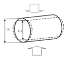
- the solid line indicates the material shape before processing, and the dotted line indicates the material shape after processing. It is a mimetic diagram for explaining cold working of axial upsetting compression. The solid line indicates the material shape before processing, and the dotted line indicates the material shape after processing.
- ⁇ Ingot> As the Ni-base superalloy to be applied to the production method of the present invention, an ingot having a composition with a ⁇ ′ molar ratio of 40% or more is prepared.
- a conventional method such as vacuum melting, vacuum arc remelting, electroslag remelting, or the like may be applied.
- the production method of the present invention described later is particularly suitable for processing a Ni-base superalloy having a ⁇ ′ molar ratio of 60% to 70%, which cannot be handled by the conventional hot forging and splitting technique.
- the working rate of the first cold working step is set to 5% or more and less than 30%.
- recrystallization of plastically deformed materials can be facilitated with increasing strain.
- the processing rate is less than 5%, the introduction of strain into the ingot is insufficient, and recrystallization cannot occur even if a heat treatment performed later is applied. Therefore, the lower limit of the processing rate in the first cold working process is set to 5%. In order to obtain a recrystallized structure more reliably, it is preferable to set the lower limit of the processing rate in the first cold working step to 8%.
- the upper limit of the processing rate in the first cold working process is set to less than 30% in consideration of the risk of defect occurrence during cold working.
- the upper limit of the processing rate in the preferred first cold working step is 20%, more preferably 15%.
- a compressive force is applied in the direction of the arrow.
- L0 is the diameter before cold working
- L1 is the dimension after compression working from the radial direction.
- Example 1 it is a method of repeating rotation of a predetermined angle in the axial direction and compression in the radial direction each time for a round bar material in which the length direction of the material is constrained. According to this method, the length direction and the radial direction hardly change as a result, but the material itself can be uniformly strained.
- the machining rate in this case is calculated using the above equation (1) with the change in the radial direction for each pass.
- the upsetting compression processing rate shown in FIG. 9 is defined by equation (2).
- Processing rate (%) ((L2-L3) / L2) ⁇ 100% (2)
- L2 is a length (height) before compression processing
- L3 is a length (height) after processing.
- the first heat treatment is performed on the cold-worked material that has been subjected to the first cold-working.
- the temperature of the first heat treatment step is set to a temperature exceeding the ⁇ ′ solvus temperature of the Ni-base superalloy to be processed (super solvus heat treatment).
- the first heat treatment step is performed at a temperature exceeding the ⁇ ′ solvus temperature of the Ni-base superalloy.
- the lower limit of the preferable first heat treatment temperature for obtaining a sounder recrystallized structure is ⁇ ′ solvus temperature plus 5 ° C., more preferably ⁇ ′ solvus temperature plus 10 ° C.
- the upper limit of the first heat treatment temperature for maintaining a healthy recrystallized structure is less than the solidus of the Ni-base superalloy. When heated above the solidus, a part of the Ni-base superalloy starts to melt, and cannot be called heat treatment. Further, if the first heat treatment temperature is excessively high, the growth of recrystallized grains may be promoted to promote the coarsening of the crystal grains. Therefore, the upper limit of the first heat treatment temperature is ⁇ ′ solvus temperature plus 40 ° C. Is preferable. However, the temperature and the solidus temperature are the lower one. More preferably, the upper limit of the first heat treatment temperature is ⁇ ′ solvus temperature plus 20 ° C. However, the temperature and the solidus temperature are the lower one.
- the recrystallization rate at which hot working can be applied to the Ni-base superalloy is 90% or more.
- the ingot has a cast structure and a coarse crystal grain size.
- macro plastic deformation in the order of mm is not uniform during hot deformation, and early cracking is likely to occur during hot working.
- the crystal structure formed by recrystallization is an equiaxed crystal and the crystal grain size can be made fine, hot deformation becomes uniform and local accumulation of dislocations hardly occurs. Therefore, the occurrence of cracks during hot working is suppressed and the hot workability is excellent.
- recrystallization grains necessary for facilitating hot working can be obtained by the combination of the first cold working step and the first heat treatment step described above.
- the processing rate of the second cold working process is set to 20% or more, and the temperature of the second heat treatment process is set to less than the ⁇ ′ solvus temperature (subsolvus heat treatment).
- the higher the cold working rate the higher the recrystallization rate in the second heat treatment step performed later, and the recrystallized grain size becomes finer.
- the lower limit of the work rate in the second cold work process is set to 20%.
- the lower limit of the processing rate of the second cold working step for producing a finer and more uniform recrystallized structure is 30%, more preferably 40%.
- the upper limit of the processing rate is not particularly set, it is realistic to set the processing rate of 80% as the upper limit when it is assumed that no cracks are generated in the second cold working step.
- the reason for setting the temperature of the second heat treatment step to less than the ⁇ ′ solvus temperature is as follows. Super solvus heat treatment exceeding the ⁇ 'solvus temperature is easy to recrystallize, but the recrystallized grain size is coarse. On the other hand, in the subsolvus heat treatment, the progress of recrystallization is slow, but the obtained recrystallized structure is fine. By combining the second cold working step and the second heat treatment step of the sub-solvus heat treatment, the recrystallized structure can be refined. Therefore, the second heat treatment step performed in the present invention is less than the ⁇ ′ solvus temperature.
- the upper limit of the preferable temperature of the second heat treatment step for more surely refining the recrystallized structure is ⁇ ′ solvus temperature minus 10 ° C., more preferably ⁇ ′ solvus temperature minus 20 ° C.
- the lower limit of the second heat treatment temperature is preferably ⁇ ′ solvus temperature minus 80 ° C.
- the lower limit of the second heat treatment temperature is more preferably ⁇ ′ solvus temperature minus 50 ° C., and further preferably ⁇ ′ solvus temperature minus 40 ° C.
- forging such as pressing and forging, stretching such as swaging, and injection processing such as shot blasting and shot peening may be applied.
- Cold working is performed to introduce strain into the Ni-base superalloy alloy ingot.
- all methods that can introduce strain can be applied, but considering that the material is an ingot, it is preferable to apply forging, stretching, and injection processing.
- the injection processing mainly introduces strain on the ingot surface, and since the ingot cracking starts from the surface, it is particularly suitable for cold working to Ni-got super heat-resistant alloy ingots that are easily broken It is. Further, from the viewpoint of processing efficiency and cost, it is preferable to apply, for example, a hydraulic press (forging) as a processing method in which the amount of strain introduction and the strain rate can be easily controlled and strain energy can be efficiently accumulated in the material.
- the present invention can be widely applied as long as the composition has a ⁇ ′ molar ratio of 40% or more, but the following compositions are particularly preferable.
- the unit of composition is mass%.
- ⁇ C: 0.001 to 0.250%> C has an effect of increasing the strength of the crystal grain boundary. This effect appears at 0.001% or more. However, if C is contained excessively, coarse carbides are formed and the strength and hot workability are lowered, so 0.250% is made the upper limit.
- a preferable lower limit is 0.005%, and more preferably 0.010%.
- a preferable upper limit is 0.150%, More preferably, it is 0.110%.
- Cr is an element that improves oxidation resistance and corrosion resistance. In order to obtain the effect, 8.0% or more is necessary. If Cr is contained excessively, an embrittlement phase such as a ⁇ phase is formed and the strength and hot workability are lowered, so the upper limit is made 22.0%.
- a preferable lower limit is 9.0%, and more preferably 9.5%.
- a preferable upper limit is 18.0%, More preferably, it is 16.0%.
- Co improves the stability of the structure and makes it possible to maintain hot workability even when a large amount of Ti as a strengthening element is contained. It is one of the selective elements that can be contained in the range of 28.0% or less in combination with other elements. Increasing the Co content improves the hot workability. In particular, in the difficult-to-work Ni-base superalloy, the addition of Co is effective. On the other hand, since Co is expensive, the cost increases.
- the preferable lower limit when Co is added for the purpose of improving hot workability is preferably 8.0%. More preferably, it is 10.0%.
- the preferable upper limit of Co is 18.0%. More preferably, it is 16.0%. If the Co addition level (the inevitable impurity level of the raw material) may be set due to the balance between the ⁇ ′ generation element and the Ni matrix generation, the lower limit of Co is set to 0%.
- Fe is one of the selective elements used as an alternative to expensive Ni and Co, and is effective in reducing alloy costs. In order to acquire this effect, it is good to determine whether to add with the combination of another element. However, if Fe is contained excessively, an embrittlement phase such as a ⁇ phase is formed and the strength and hot workability are lowered, so the upper limit of Fe is 10.0%. A preferable upper limit is 9.0%, more preferably 8.0%. On the other hand, if the Fe addition level (inevitable impurity level of the raw material) is allowed due to the balance of the ⁇ ′ generating element and the Ni matrix generation, the lower limit of Fe is set to 0%.
- Mo contributes to the solid solution strengthening of the matrix and has the effect of improving the high temperature strength. In order to obtain this effect, 2.0% or more is necessary. However, if Mo is excessive, an intermetallic compound phase is formed and the high-temperature strength is impaired, so the upper limit is made 7.0%.
- a preferred lower limit is 2.5%, more preferably 3.0%.
- a preferable upper limit is 5.0%, More preferably, it is 4.0%.
- W is one of the selective elements that contribute to the solid solution strengthening of the matrix. If W is excessive, a harmful intermetallic compound phase is formed and the high temperature strength is impaired, so the upper limit is made 6.0%. A preferable upper limit is 5.5%, and more preferably 5.0%. In order to exhibit the above-described effect of W more reliably, the lower limit of W is preferably set to 1.0%. Moreover, the solid solution strengthening effect can be exhibited more by adding W and Mo in combination. In the case of composite addition, W is preferably 0.8% or more. In addition, when it is good also considering W as an additive-free level (inevitable impurity level of a raw material) by sufficient addition of Mo, the minimum of W shall be 0%.
- V is one of the selective elements useful for strengthening the solid solution of the matrix and strengthening the grain boundaries by forming carbides.
- the lower limit of V is preferably set to 0.5%.
- the upper limit of V is set to 1.2%.
- a preferable upper limit is 1.0%, and more preferably 0.8%.
- V may be an additive-free level (inevitable impurity level of the raw material) due to balance with other alloy elements in the alloy, the lower limit of V is set to 0%.
- Al is an essential element that forms a ⁇ ′ (Ni 3 Al) phase that is a strengthening phase and improves high-temperature strength. In order to obtain the effect, at least 2.0% is necessary. However, excessive addition reduces the hot workability and causes material defects such as cracks during processing. Limited to 0%. A preferred lower limit is 2.5%, more preferably 3.0%. Moreover, a preferable upper limit is 7.5%, More preferably, it is 7.0%.
- Ti like Al, is an essential element that forms a ⁇ ′ phase and enhances the high temperature strength by solid solution strengthening of the ⁇ ′ phase. In order to obtain the effect, at least 0.5% is necessary. However, excessive addition causes the gamma prime phase to become unstable at high temperature, leading to coarsening at high temperature and forming a harmful eta (eta) phase. Since the hot workability is impaired, the upper limit of Ti is set to 7.0%. Considering the balance of other ⁇ ′ forming elements and the matrix, the preferable lower limit of Ti is 0.7%, more preferably 0.8%. Moreover, a preferable upper limit is 6.5%, More preferably, it is 6.0%.
- Nb is one of the selective elements that forms a ⁇ 'phase like Al and Ti and enhances the high-temperature strength by solid solution strengthening of the ⁇ ' phase.
- the lower limit of Nb is preferably set to 2.0%.
- the upper limit of Nb is 4.0%.
- a preferable upper limit is 3.5%, more preferably 2.5%.
- the lower limit of Nb is set to 0%.
- Ta like Al and Ti, is one of the selective elements that forms a ⁇ ′ phase and enhances the high temperature strength by solid solution strengthening of the ⁇ ′ phase.
- the lower limit of Ta is preferably set to 0.3%.
- excessive addition of Ta causes the gamma prime phase to become unstable at high temperatures, leading to coarsening at high temperatures and forming a harmful ⁇ (eta) phase, which impairs hot workability. 0.0%. Preferably it is 2.5% or less.
- the lower limit of Ta is set to 0%.
- Hf is one of the selective elements useful for improving the oxidation resistance of alloys and strengthening grain boundaries by forming carbides.
- the lower limit of Hf is preferably set to 0.1%.
- the upper limit of Hf is set to 1.0%. If the Hf is allowed to be a non-additive level raw material (inevitable impurity level) due to the balance with other alloy elements in the alloy, the lower limit of Hf is set to 0%.
- B is an element that improves the grain boundary strength and improves the creep strength and ductility. To obtain this effect, a minimum of 0.001% is required. On the other hand, B has a great effect of lowering the melting point, and when coarse boride is formed, workability is hindered. Therefore, B should be controlled not to exceed 0.300%.
- a preferable lower limit is 0.003%, and more preferably 0.005%.
- a preferable upper limit is 0.20%, More preferably, it is 0.020%.
- Zr has the effect of improving the grain boundary strength in the same manner as B, and is at least 0.001% to obtain this effect.
- the upper limit is made 0.300%.
- a preferable lower limit is 0.005%, and more preferably 0.010%.
- a preferable upper limit is 0.250%, More preferably, it is 0.200%.
- the balance other than the elements to be described is Ni, but naturally unavoidable impurities are included.
- Example 1 The following examples further illustrate the present invention.
- the Ni-base superalloy was melted in vacuum, and a Ni-base superalloy A ingot ( ⁇ 40 mm ⁇ 200 mmL) was prepared by lost wax precision casting.
- Table 1 shows the chemical composition of the Ni-base superalloy A.
- the amount of ⁇ ′ that can be precipitated in an equilibrium state and the ⁇ ′ solvus temperature of a Ni-base superalloy are determined in principle by the alloy composition.
- the ⁇ ′ solvus temperature and ⁇ ′ mole ratio of the Ni-base superalloy A are calculated using commercially available calculation software JMatPro (Version 8.0.1, product of Sente Software Ltd.), and the ⁇ ′ solvus temperature is 1188 ° C.
- the ⁇ ′ mol% at 700 ° C. was 69%.
- a sample for compression test of ⁇ 13 mm ⁇ 100 mmL was taken from the ingot of the obtained Ni-base superheat-resistant alloy A from the direction parallel to the longitudinal direction of the ingot.
- a compressed sample of ⁇ 13 mm ⁇ 100 mmL was compressed by a plurality of passes from the radial direction.
- the compression directions of the different compression paths were as follows. First pass: First compression in an arbitrary radial direction. Second pass: Second compression by rotating in the 90 ° direction with reference to the direction of the first compression. Third pass: Compressed by rotating in the plus 45 ° direction with reference to the first compression direction. Fourth pass: Compressed by rotating in the minus 45 ° direction based on the first compression direction. Fifth pass: Compressed by rotating in the plus 22.5 ° direction with reference to the first pass direction. Sixth pass: Compressed by rotating in the minus 22.5 ° direction with reference to the first pass direction.
- Seventh pass Compressed by rotating in the plus 22.5 ° direction with reference to the direction of the second pass.
- Eighth pass Compressed by rotating in the minus 22.5 ° direction with reference to the direction of the second pass.
- the second to eighth passes were performed in the above order.
- Table 2 shows the number of machining passes. As the display method, for example, the number of machining passes performed up to the second pass is 2, and the number of machining passes up to the eighth pass is represented as 8.
- the compression processing temperature was room temperature, and the compression strain rate was 0.1 / s.
- the material subjected to the first cold working step was subjected to a first heat treatment step at a predetermined temperature and holding time.
- Table 2 shows the conditions of the first cold working process.
- the heat treatment conditions for the “sub-solvus treatment” shown in Table 2 as the first heat treatment step are 1150 ° C. ⁇ 30 minutes
- the heat treatment conditions for the “super solvus treatment (A)” are 1200 ° C. ⁇ 5 minutes
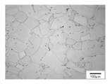
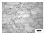
- the heat treatment condition for “treatment (B)” is 1200 ° C. ⁇ 30 minutes. After the heat treatment, all samples were air-cooled. A sample for micro observation having a thickness of 5 mm was cut out from the round bar after the first heat treatment step, and observed with an optical microscope from the axial direction of the round bar.
- the corrosive liquid for structure observation was Kalling liquid, and the recrystallization rate was calculated by the area ratio of the recrystallized structure.
- the measurement results of the recrystallization rate are also shown in Table 2. Microphotographs of examples and comparative examples are shown in FIGS.
- Example 2 The Ni-base superheat-resistant alloy was melted in vacuum to prepare an Ni-base superheat-resistant alloy B ingot ( ⁇ 100 mm ⁇ 110 mmL).
- Table 3 shows the chemical composition of the Ni-base superalloy B.
- the ⁇ ′ solvus temperature and the ⁇ ′ mole ratio of the Ni-base superalloy B were calculated using commercially available calculation software JMatPro.
- the ⁇ ′ solvus temperature was 1162 ° C.
- the ⁇ ′ mol% at 700 ° C. was 46%.
- a sample for compression test of ⁇ 22 mm ⁇ 55 mmL in the direction parallel to the axial direction of the ingot was taken from the 1/4 diameter position of the ingot of the obtained Ni-base superalloy B.
- the first cold working step a round bar of ⁇ 22 mm ⁇ 55 mmL was set up from the axial direction, and cold working was performed at a working rate of 10%.
- the subsequent first heat treatment step was not performed.
- a first heat treatment step was performed.
- the conditions of the first heat treatment step were as follows: holding temperature 1180 ° C. ⁇ 8 hours, cooling to 500 ° C. at a cooling rate of 60 ° C./h, taking the sample from the heat treatment furnace at 500 ° C., and air cooling.
- the microstructure was evaluated by the same method as in Example 1, and it was confirmed that the recrystallization rate was 100%.
- the average grain size was 320 ⁇ m.
- the sample after the compression test that has undergone the first cold working step and the first heat treatment step is further subjected to cold working with a working rate of 30% by upsetting compression from the axial direction as the second cold working step. After that, a second heat treatment step was performed.
- the condition of the second heat treatment step was a holding temperature of 1130 ° C. ⁇ 30 minutes, followed by air cooling.
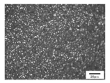
- the sample after the compression test subjected to the second cold working step and the second heat treatment step was cut so as to pass through the center line in the length direction, and the microstructure at the 1 / 4D (D is diameter) position was observed. .
- the corrosion was electrolytic corrosion (electrolytic corrosion solution: 10% oxalic acid aqueous solution, corrosion voltage: 4 V, corrosion time 2 seconds).
- the structure thus obtained is shown in FIG. 6, and the average particle size was 10.6 ⁇ m (ASTM # 9.7). From this result, it can be seen that the crystal grains can be sufficiently refined by applying the method for producing a Ni-base superalloy according to the present invention.
- Example 3 The Ni-base superheat-resistant alloy was melted in vacuum to prepare an Ni-base superheat-resistant alloy C ingot ( ⁇ 100 mm ⁇ 110 mmL).
- Table 4 shows the chemical composition of the Ni-base superalloy B.
- the ⁇ ′ solvus temperature and the ⁇ ′ mole ratio of the Ni-base superalloy C were calculated using commercially available calculation software JMatPro.
- the ⁇ ′ solvus temperature was 1235 ° C.
- the ⁇ ′ mol% was 72%.
- a sample for compression test of ⁇ 22 mm ⁇ 55 mmL in the direction parallel to the axial direction of the ingot was taken from the 1/4 diameter position of the ingot of the obtained Ni-base superalloy C.
- first cold working step a round bar of ⁇ 22 mm ⁇ 55 mmL was set up from the axial direction, and cold working was performed at a working rate of 10%.
- the processing rate is as in the above equation (2).
- the subsequent first heat treatment step was not performed.
- a first heat treatment step was performed. The conditions of the first heat treatment step were as follows: holding temperature 1250 ° C. ⁇ 8 hours, cooling to 500 ° C. at a cooling rate of 60 ° C./h, taking the sample from the heat treatment furnace at 500 ° C., and air cooling.
- the microstructure was evaluated by the same method as in Example 1, and it was confirmed that the recrystallization rate was 100%.
- the recrystallized grain size was evaluated by the ASTM method, the average grain size was 290 ⁇ m.
- the sample after the compression test that has undergone the first cold working step and the first heat treatment step is further subjected to cold working at a working rate of 30% from the axial direction as the second cold working step, The heat treatment process was performed.
- the conditions for the second heat treatment step were air cooling after holding at a holding temperature of 1200 ° C. for 30 minutes.
- the sample after the compression test subjected to the second cold working step and the second heat treatment step was cut so as to pass through the center line in the length direction, and the microstructure at the 1 / 4D (D is diameter) position was observed. .
- electrolytic corrosion was adopted (electrolytic corrosion solution: 10% oxalic acid aqueous solution, corrosion voltage: 4 V, corrosion time 1.5 seconds).
- the resulting structure is shown in FIG.
- the average particle size was 9.8 ⁇ m (ASTM # 10). From this result, it can be seen that the crystal grains can be sufficiently refined by applying the method for producing a Ni-base superalloy according to the present invention.
- Example 4 An ingot ( ⁇ 100 mm ⁇ 110 mmL) of a Ni-base superalloy D was manufactured by vacuum melting. Table 5 shows the chemical composition of the Ni-base superalloy D. The ⁇ ′ solvus temperature and ⁇ ′ mole ratio of this alloy were calculated by a commercially available calculation software JMatPro. The ⁇ ′ solvus temperature was 1159 ° C., and 700 ° C. ⁇ ′ mol% was 47%.
- a compression sample of ⁇ 22 mm ⁇ 35 mmL in the direction parallel to the axial direction of the ingot was taken from the 1/4 diameter position of the ingot of the obtained Ni-based superalloy D.
- a round bar of ⁇ 22 mm ⁇ 35 mmL was upset and forged from the axial direction.
- the forging processing rate was 10%.
- the processing rate was calculated according to the formula (2).
- a first heat treatment step was performed.
- the conditions of the first heat treatment step were as follows: holding temperature 1180 ° C. ⁇ 8 hours, cooling to 500 ° C. at a cooling rate of 60 ° C./h, taking the sample from the heat treatment furnace at 500 ° C., and air cooling.
- Tensile test pieces were collected from the heat-treated material and subjected to a tensile test.
- a tensile test piece a reduced version of ASTM standard was adopted. The total test length was 30 mm, the gauge distance was 7 mm, and the diameter was 2 mm. The strain rate was 0.1 / S, and the tensile test temperatures were room temperature (22 ° C.) and 800 ° C. The test temperature of 800 ° C. simulates hot working such as decomposition forging.
- a tensile test piece was collected from the as-cast material and a tensile test was performed under the same tensile conditions. The results are shown in Table 6.
- the first cold working step and the first heat treatment step of the present invention significantly improved the high temperature ductility of the difficult-to-work Ni-base superalloy having a ⁇ ′ mol% of 40% or more. .
- hot working can be sufficiently performed if a drawing value of about 60% can be secured.
- the diaphragm could be achieved to about 60% even at a relatively low temperature of 800 ° C.
- hot working is performed at a temperature higher than 800 ° C., it is understood that hot working can be easily performed by applying the method of the present invention.
- the method for producing a Ni-base superalloy according to the present invention described above is applied to, for example, production of an intermediate material for agglomeration, the ⁇ ′ molar ratio, which has been conventionally difficult to perform hot working such as hot forging. Hot working such as partial forging of difficult-to-process Ni-base superalloys of 40% or more can be easily performed. Thereby, it is possible to manufacture, for example, an aircraft or a high-performance turbine disk for power generation using a high ⁇ ′-containing Ni-based superalloy.
Abstract
Description
しかし、γ’相の増加は、熱間加工時の変形抵抗が高くなり、鍛造加工が困難になる。また、γ’モル率が高いほど、鋳造凝固時の偏析傾向が強くなり、インゴットでの高温不安定相や鋳造欠陥が多くなり、インゴットの熱間鍛造性が低下する。その上、γ’生成元素であるAl、Tiの大量添加は合金の固相線温度低下、再結晶温度上昇も起こして、熱間鍛造温度領域を狭くさせる(一般に熱間鍛造は固相線温度以下、再結晶温度以上で行われる)。従来γ’モル率が40%以上では事実上鍛造できる温度範囲がほぼ存在せず、熱間鍛造が困難とされている。そのため、γ’モル率が高いNi基超耐熱合金の製造には、鍛造加工の困難を避けて、鋳造ままで使用する鋳物や、初期インゴットを粉末焼結で製造する粉末冶金法などの提案がある(例えば、特開平10-46278号公報(特許文献1))。
本発明の目的は、高γ’相含有Ni基超耐熱合金を製造する際に問題となっていた、熱間加工を容易とするNi基超耐熱合金の製造方法を提供するものである。
前記Ni基超耐熱合金インゴットを加工率5%以上30%未満で冷間加工を行う第1の冷間加工工程と、
前記第1の冷間加工を行った冷間加工材にγ’固溶温度(以下、γ’ソルバス温度と記す)を超える温度で熱処理する第1の熱処理工程と
を含むNi基超耐熱合金の製造方法が提供される。
前記第1の熱処理を行う温度が、ガンマプライム固溶温度プラス40℃以下かつ前記Ni基超耐熱合金の固相線温度未満であることが好ましい。
前記第1の熱処理工程を施された熱処理材に加工率20%以上で第2の冷間加工を行う第2冷間加工工程と、
前記第2の冷間加工を行った第2冷間加工材にγ’ソルバス温度未満の温度で熱処理する第2の熱処理工程をさらに含むことが好ましい。
前記第2の熱処理を行う温度が、ガンマプライム固溶温度マイナス80℃以上であることが好ましい。
本発明の一具体例では、前記第1の冷間加工または前記第2の冷間加工は、鍛造、延伸加工、噴射加工の何れかまたは2種以上の組合わせであることが好ましい。
本発明の一具体例では、Ni基超耐熱合金の組成は質量%で、C:0.001~0.250%、Cr:8.0~22.0%、Co:28.0%以下、Mo:2.0~7.0%、W:6.0%以下、Al:2.0~8.0%、Ti:0.5~7.0%、Nb:4.0%以下、Ta:3.0%以下、Fe:10.0%以下、V:1.2%以下、Hf:1.0%以下、B:0.001~0.300%、Zr:0.001~0.300%を含み、残部はNi及び不純物からなることが好ましい。
<インゴット>
本発明製造方法に適用するNi基超合金はγ’モル率が40%以上となる組成を有するインゴットを準備する。インゴットの製造方法は、真空溶解と真空アーク再溶解やエレクトロスラグ再溶解等の常法を適用すれば良い。なお、後述する本発明の製造方法は、特に、従来の熱間鍛造分塊技術で対応できないγ’モル率が60%~70%Ni基超合金の加工に好適である。
本発明では、先ず、上記インゴットに冷間で加工を行う。冷間加工と再結晶熱処理における再結晶のメカニズムはまだ完全解明に至っていないが、本発明で冷間加工を適用した理由は、まず、熱間鍛造加工に比較して、加工過程での回復や動的再結晶が行われず、塑性加工によるひずみエネルギーを最も有効に材料に導入できるためである。次に、インゴットのままでは不均一に分布する共晶γ’相、炭化物、他析出相が存在し、μmオーダーのミクロ塑性変形の不均一性を利用して、ひずみ勾配が高いポイントを作るのに有利であるからである。ひずみ勾配が高いサイトは再結晶核生成起点になりやすい。この冷間加工を適用することで、低い冷間加工率と後述する適切な熱処理により首尾よく再結晶組織を得ることができる。
一方、加工率が高いほど、後に行う熱処理にて再結晶が容易になり、再結晶粒を微細とすることができるため、第1の冷間加工工程の加工率は高い方が好ましい。しかし、鋳造ままのインゴットあるいはソーキング熱処理を行ったインゴットはデントライトの粗大組織を呈し、インゴット中に凝固偏析や鋳造欠陥などが存在して、冷間加工延性が限られる。そのため、冷間加工時の欠陥発生リスクを考慮し、第1の冷間加工工程の加工率の上限を30%未満とする。好ましい第1の冷間加工工程の加工率の上限は20%であり、さらに好ましくは15%である。
例えば、図8に示す径方向圧縮の加工率は下記の式(1)で定義する。
加工率(%)=((L0-L1)/L0)×100%…(1)
ここで、L0は冷間加工前の径であり、L1は径方向からの圧縮加工後の寸法である。
なお、例えば、径方向からの圧縮としては、鍛伸のように径の断面積を小さくして、素材の長さを長尺とする加工方法があり、その場合は、鍛伸前の径と鍛伸後の径とで加工率を求めると良い。また、本発明を適用する場合、後述の実施例1に示すような加工方法がある。例えば、素材の長さ方向を拘束した丸棒材に対して、軸方向に所定の角度の回転と、その都度径方向の圧縮を繰り返す方法である。この方法によれば、長さ方向と径方向は結果として殆ど変化しないが、材料自体に均一に歪を加えることができる。この場合の加工率は、1パス毎の径方向の変化で上記(1)式を用いて計算する。
なお、図9に示す据え込み圧縮の加工率は式(2)で定義する。
加工率(%)=((L2-L3)/L2)×100%…(2)
ここで、L2は圧縮加工前の長さ(高さ)、L3は加工後の長さ(高さ)である。
次に本発明による製造方法では、前述の第1の冷間加工を行った冷間加工材に対して、第1の熱処理を行う。第1の熱処理工程の温度は被加工Ni基超耐熱合金のγ’ソルバス温度を超える温度とする(スーパーソルバス熱処理)。本発明者の検討によれば、第1の冷間加工を行った冷間加工材に対して熱処理を行うと、熱処理温度の上昇により再結晶が進行することが分かった。特にγ’ソルバス温度上下では挙動が大きく変わることを知見した。γ’ソルバス温度以下では低ひずみ変形の健全な再結晶組織を得られないが、γ’ソルバス温度を超える温度域では、95%以上の再結晶組織が得られた。そのため、第1の熱処理工程をNi基超耐熱合金のγ’ソルバス温度を超える温度で行う。より健全な再結晶組織を得るための好ましい第1の熱処理温度の下限はγ’ソルバス温度プラス5℃であり、より好ましくはγ’ソルバス温度プラス10℃である。
この第1の冷間加工工程と、第1の熱処理工程の組合せにより、Ni基超耐熱合金に熱間加工を適用することが可能な、再結晶率を90%以上とすることができる。
インゴットは鋳造組織を有し、結晶粒径が粗大である。また、冷却方向に依存する異方性を持つ柱状晶が存在することが多い。このような鋳造組織は熱間変形時にmmオーダーのマクロ塑性変形が不均一となり、熱間加工時に早期の割れが発生しやすい。再結晶で作る結晶組織は等軸結晶であり、結晶粒径を微細にすることができるため、熱間変形が均一となり、局所的な転位の蓄積が起こり難い。それため、熱間加工時に割れの発生が抑制され、熱間加工性に優れている。
本発明では、上述した第1の冷間加工工程と第1の熱処理工程の組合せにより、熱間加工を容易にするのに必要な再結晶粒を得ることができるが、この再結晶組織を微細とするには、更に第2の冷間加工工程と第2の熱処理工程を行うことが好ましい。
本発明は第2の冷間加工工程の加工率を20%以上とし、第2の熱処理工程の温度はγ’ソルバス温度未満(サブソルバス熱処理)とする。上述したように冷間での加工率が高いほど後に行う第2の熱処理工程で再結晶率が高く、再結晶粒径が微細になる。健全な再結晶組織を得て、後工程の熱間鍛造で十分な加工延性を得るために、第2の冷間加工工程の加工率の下限を20%とする。より微細均一な再結晶組織を作るための好ましい第2の冷間加工工程の加工率の下限は30%であり、より好ましくは40%である。一方、加工率の上限は特に設定しないが、第2の冷間加工工程で割れが発生しないことを目安とすると、80%の加工率を上限とするのが現実的である。
再結晶の結晶粒をさらに微細化させることにより、局所的な転位の蓄積を抑制する効果を向上させ、熱間変形の均一性をさらに向上させ、熱間加工性が一層向上することができる。
<C:0.001~0.250%>
Cは、結晶粒界の強度を高める効果を有する。この効果は、0.001%以上で現れるが、Cを過剰に含有した場合は、粗大な炭化物が形成され、強度、熱間加工性を低下させるため、0.250%を上限とする。好ましい下限は0.005%であり、より好ましくは0.010%である。また、好ましい上限は0.150%であり、より好ましくは0.110%である。
Crは、耐酸化性、耐食性を向上させる元素である。その効果を得るには、8.0%以上が必要である。Crを過剰に含有すると、σ相などの脆化相を形成し、強度、熱間加工性を低下させるので、上限は22.0%とする。好ましい下限は9.0%であり、より好ましくは9.5%である。また、好ましい上限は18.0%であり、より好ましくは16.0%である。
Coは、組織の安定性を改善し、強化元素であるTiを多く含有しても熱間加工性を維持することを可能とする。他元素との組み合わせにより、28.0%以下の範囲で含有することができる選択元素の一つである。Co含有量を高めると熱間加工性は向上し、特に難加工性のNi基超耐熱合金においては、Coの添加は有効である。一方で、Coは高価であるため、コストが上昇する。熱間加工性を向上させる目的でCoを添加する場合の好ましい下限は8.0%とすると良い。更に好ましくは10.0%である。また、Coの好ましい上限は18.0%とする。より好ましくは16.0%である。なお、γ’生成元素やNiマトリックス生成のバランスにより、Coを無添加レベル(原料の不可避不純物レベル)としても良い場合は、Coの下限を0%とする。
Feは、高価なNi、Coの代替として用いる選択元素の一つであり、合金コストの低減に有効である。この効果を得るには、他元素の組み合わせで添加するかどうかを決定すると良い。ただし、Feを過剰に含有するとσ相などの脆化相を形成し、強度、熱間加工性を低下させるので、Feの上限は10.0%とする。好ましい上限は9.0%であり、より好ましくは8.0%である。一方、γ’生成元素やNiマトリックス生成のバランスにより、Feを無添加レベル(原料の不可避不純物レベル)としても良い場合は、Feの下限を0%とする。
Moは、マトリックスの固溶強化に寄与し、高温強度を向上させる効果がある。この効果を得るためには、2.0%以上が必要であるが、Moが過剰となると金属間化合物相が形成されて高温強度を損なうため、上限を7.0%とする。好ましい下限は2.5%であり、より好ましくは3.0%である。また、好ましい上限は5.0%であり、より好ましくは4.0%である。
Wは、Moと同様に、マトリックスの固溶強化に寄与する選択元素の一つである。Wが過剰となると有害な金属間化合物相が形成されて高温強度を損なうため、上限を6.0%とする。好ましい上限は5.5%であり、より好ましくは5.0%である。前述のWの効果をより確実に発揮させるには、Wの下限を1.0%とすると良い。また、WとMoとを複合添加することにより、より固溶強化効果が発揮できる。複合添加の場合のWは0.8%以上の添加が好ましい。なお、Moの十分な添加により、Wを無添加レベル(原料の不可避不純物レベル)としても良い場合は、Wの下限を0%とする。
Vは、マトリックスの固溶強化、炭化物生成による粒界強化に有用な選択元素の一つである。このVの効果をより確実に発揮させるには、Vの下限を0.5%とすると良い。ただし、Vの過度の添加は製造過程の高温不安定相の生成を招き、製造性および高温力学性能に悪影響を招くので、Vの上限を1.2%とする。好ましい上限は1.0%であり、より好ましくは0.8%である。なお、合金中の他合金元素のとのバランスにより、Vを無添加レベル(原料の不可避不純物レベル)としても良い場合は、Vの下限を0%とする。
Alは、強化相であるγ’(Ni3Al)相を形成し、高温強度を向上させる必須元素である。その効果を得るためには最低2.0%が必要であるが、過度の添加は熱間加工性を低下させ、加工中の割れなどの材料欠陥の原因となるので、2.0~8.0%に限定する。好ましい下限は2.5%であり、より好ましくは3.0%である。また、好ましい上限は7.5%であり、より好ましくは7.0%である。
TiもAlと同様にγ’相を形成し、γ’相を固溶強化して高温強度を高める必須元素である。その効果を得るためには最低0.5%必要であるが、過度の添加はガンマプライム相が高温で不安定となって高温での粗大化を招くとともに有害なη(イータ)相を形成し、熱間加工性を損なうのでTiの上限を7.0%とする。他のγ’形成元素やマトリックスのバランスを考慮すると、Tiの好ましい下限は0.7%であり、より好ましくは0.8%である。また、好ましい上限は6.5%であり、より好ましくは6.0%である。
Nbは、AlやTiと同様にγ’相を形成し、γ’相を固溶強化して高温強度を高める選択元素の一つである。このNbの効果をより確実に発揮させるには、Nbの下限を2.0%とすると良い。ただし、Nbの過度の添加は有害なδ(デルタ)相を形成し、熱間加工性を損なうのでNbの上限を4.0%とする。好ましい上限は3.5%であり、より好ましくは2.5%である。他のγ’形成元素の添加により、Nbを無添加レベル(原料の不可避不純物レベル)としても良い場合は、Nbの下限を0%とする。
Taは、AlやTiと同様にγ’相を形成し、γ’相を固溶強化して高温強度を高める選択元素の一つである。このTaの効果をより確実に発揮させるには、Taの下限を0.3%とすると良い。ただし、Taの過度の添加はガンマプライム相が高温で不安定となって高温での粗大化を招くとともに有害なη(イータ)相を形成し、熱間加工性を損なうのでTaの上限を3.0%とする。好ましくは2.5%以下である。一方、TiやNbなどのγ’形成元素添加やマトリックスのバランスにより、Taは無添加レベル(原料の不可避不純物レベル)としても良い場合は、Taの下限を0%とする。
Hfは、合金の耐酸化性向上、炭化物生成による粒界強化に有用な選択元素の一つである。このHfの効果をより確実に発揮させるには、Hfの下限を0.1%とすると良い。ただし、Hfの過度の添加は製造過程の酸化物生成、高温不安定相の生成を招き、製造性および高温力学性能に悪影響を招くので、Hfの上限を1.0%とする。なお、合金中の他合金元素のとのバランスにより、Hfは無添加レベルの原料(不可避不純物レベル)としても良い場合は、Hfの下限を0%とする。
Bは、粒界強度を向上させ、クリープ強度、延性を改善する元素である。この効果を得るには最低0.001%が必要となる。一方でBは融点を低下させる効果が大きいこと、また、粗大なホウ化物が形成されると加工性が阻害されることから、0.300%を超えないように制御すると良い。好ましい下限は0.003%であり、より好ましくは0.005%である。また、好ましい上限は0.20%であり、より好ましくは0.020%である。
Zrは、Bと同様に粒界強度を向上させる効果を有しており、この効果を得るには最低0.001%とする。一方でZrが過剰となると、やはり融点の低下を招き、高温強度、熱間加工性が阻害されるため、上限は0.300%とする。好ましい下限は0.005%であり、より好ましくは0.010%である。また、好ましい上限は0.250%であり、より好ましくは0.200%である。
以上、説明する元素以外の残部はNiとするが、当然、不可避的な不純物は含まれる。
以下の実施例で本発明を更に詳しく説明する。
Ni基超耐熱合金を真空溶解し、ロストワックス精密鋳造でNi基超耐熱合金Aのインゴット(φ40mm×200mmL)を作製した。Ni基超耐熱合金Aの化学組成を表1に示す。Ni基超合金は平衡状態で析出できるγ’の量やγ’ソルバス温度は原理的にその合金組成で決められる。Ni基超耐熱合金Aのγ’ソルバス温度とγ’モル率は市販計算ソフトJMatPro(Version 8.0.1、Sente Software Ltd.社製品)を用いて計算し、γ’ソルバス温度は1188℃であり、700℃のγ’モル%は69%であった。
得られたNi基超耐熱合金Aのインゴットからインゴットの長手方向と平行の方向からφ13mm×100mmLの圧縮試験用サンプルを採取した。

1パス目:径方向の任意方向で第1回目の圧縮。
2パス目:第1回目の圧縮の方向を基準に、90°方向に回転させて第2の圧縮。
3パス目:第1回目の圧縮の方向を基準に、プラス45°方向に回転させて圧縮。
4パス目:第1回目の圧縮の方向を基準に、マイナス45°方向に回転させて圧縮。
5パス目:第1パス方向を基準に、プラス22.5°方向に回転させて圧縮。
6パス目:第1パス方向を基準に、マイナス22.5°方向に回転させて圧縮。
7パス目:第2パスの方向を基準に、プラス22.5°方向に回転させて圧縮。
8パス目:第2パスの方向を基準に、マイナス22.5°方向に回転させて圧縮。
上記の順番で2パス目~8パス目までそれぞれ実施した。それぞれの加工パス数を表2に示す。表示の仕方は、例えば、2パス目まで実施したものは加工パス数を2、8パス目まで実施したものは加工パス数を8というように表記した。
なお、加工率の計算は、上記の(1)式の通り、加工(圧縮)率(%)=(L0-L1)/L0×100%として計算し、L0とL1はパス毎の径方向の圧縮前後寸法である。圧縮加工温度は室温、圧縮のひずみ速度はいずれも0.1/sであった。
また、第1の熱処理工程後の丸棒から厚み5mmのミクロ観察用サンプルを切り出し、丸棒の軸方向から光学顕微鏡観察を行った。組織観察の腐食液はKalling液、再結晶率の算出は再結晶組織の面積率で算出した。再結晶率の測定結果を表2に併せて示す。実施例および比較例のミクロ写真を図1~図5に示す。

Ni基超耐熱合金を真空溶解し、Ni基超耐熱合金Bのインゴット(φ100mm×110mmL)を作製した。Ni基超耐熱合金Bの化学組成を表3に示す。Ni基超耐熱合金Bのγ’ソルバス温度とγ’モル率は市販計算ソフトJMatProで計算し、γ’ソルバス温度は1162℃であり、700℃のγ’モル%は46%であった。
得られたNi基超耐熱合金Bのインゴットの1/4直径位置からインゴットの軸方向と平行方向でφ22mm×55mmLの圧縮試験用サンプルを採取した。

次に、第1の熱処理工程を実施した。第1の熱処理工程の条件は、保持温度1180℃×8時間保持後、60℃/hの冷却速度で500℃まで冷却し、500℃で熱処理炉からサンプルを取り出して空冷した。
第1の冷間加工工程と第1の熱処理工程を経た圧縮試験後のサンプルに、さらに、第2の冷間加工工程として、軸方向から据え込み圧縮で加工率30%の冷間加工を行った後、第2の熱処理工程を施した。第2の熱処理工程の条件は、保持温度1130℃×30分保持後空冷した。
第2の冷間加工工程と第2の熱処理工程を施した圧縮試験後のサンプルを長さ方向の中心線を通るように切断し、1/4D(Dは直径)位置のミクロ組織を観察した。腐食は電解腐食を採用した(電解腐食液:10%シュウ酸水溶液、腐食電圧:4V、腐食時間2秒)。これで得られた組織を図6に示し、その平均粒径は10.6μm(ASTM#9.7)であった。
この結果から、本発明で規定するNi基超耐熱合金の製造方法を適用することにより、結晶粒の微細化が十分に図れることがわかる。
Ni基超耐熱合金を真空溶解し、Ni基超耐熱合金Cのインゴット(φ100mm×110mmL)を作製した。Ni基超耐熱合金Cの化学組成を表4に示す。Ni基超耐熱合金Cのγ’ソルバス温度とγ’モル率は市販計算ソフトJMatProで計算し、γ’ソルバス温度は1235℃であり、γ’モル%は72%であった。
得られたNi基超耐熱合金Cのインゴットの1/4直径位置からインゴットの軸方向と平行方向でφ22mm×55mmLの圧縮試験用サンプルを採取した。

次に、第1の熱処理工程を実施した。第1の熱処理工程の条件は、保持温度1250℃×8時間保持後、60℃/hの冷却速度で500℃まで冷却し、500℃で熱処理炉からサンプルを取り出して空冷した。
第1の冷間加工工程と第1の熱処理工程を経た圧縮試験後のサンプルをさらに、第2の冷間加工工程として、軸方向から加工率30%の冷間加工を行った後、第2の熱処理工程を施した。第2の熱処理工程の条件は、保持温度1200℃×30分保持後空冷した。
第2の冷間加工工程と第2の熱処理工程を施した圧縮試験後のサンプルを長さ方向の中心線を通るように切断し、1/4D(Dは直径)位置のミクロ組織を観察した。腐食は電解腐食を採用した(電解腐食液:10%シュウ酸水溶液、腐食電圧:4V、腐食時間1.5秒)。これで得られた組織を図7に示す。その平均粒径は9.8μm(ASTM#10)であった。
この結果から、本発明で規定するNi基超耐熱合金の製造方法を適用することにより、結晶粒の微細化が十分に図れることがわかる。
真空溶解してNi基超耐熱合金Dのインゴット(φ100mm×110mmL)を作製した。Ni基超耐熱合金Dの化学組成を表5に示す。本合金のγ’ソルバス温度とγ’モル率は市販計算ソフトJMatProで計算し、γ’ソルバス温度は1159℃であり、700℃γ’モル%は47%であった。

第1の冷間加工工程は、φ22mm×35mmLの丸棒を軸方向から据え込み鍛造した。鍛造の加工率10%であった。加工率は式(2)に従って算出した。次に、第1の熱処理工程を実施した。第1の熱処理工程の条件は、保持温度1180℃×8時間保持後、60℃/hの冷却速度で500℃まで冷却し、500℃で熱処理炉からサンプルを取り出して空冷した。
上記熱処理材料から引張試験片を採取し、引張試験を行った。引張試験片はASTM標準の縮小版を採用した。試験全長30mm、標点距離7mm、直径2mmであった。なお、歪み速度は0.1/Sであり、引張試験温度は室温(22℃)と800℃で行った。なお、試験温度800℃は分解鍛造等の熱間加工を模擬したものである。また、比較例として、鋳造ままの材料から引張試験片を採取して、同様な引張条件で引張試験を行った。その結果を表6に示す。

通常、1050~1100℃での熱間加工では、絞りの値が60%程度確保できれば十分に熱間加工ができるものである。表6に示すように、本発明では、800℃という比較的低い温度であっても絞りが約60%に達成できた。通常、熱間加工は800℃より高い温度で行うことから本発明方法の適用により、熱間加工を容易に行えることが分かる。
Claims (7)
- ガンマプライム(γ’)相が40モル%以上となる組成を有するNi基超耐熱合金インゴットを準備する工程と、
前記Ni基超耐熱合金インゴットを加工率5%以上、30%未満で冷間加工を行う第1の冷間加工工程と、
前記第1の冷間加工を行った冷間加工材にガンマプライム固溶温度を超える温度で熱処理する第1の熱処理工程と
を含む、Ni基超耐熱合金の製造方法。 - 前記第1の熱処理を行う温度が、ガンマプライム固溶温度プラス40℃以下、かつ前記Ni基超耐熱合金の固相線温度未満である請求項1に記載のNi基超耐熱合金の製造方法。
- 前記第1の熱処理を施された熱処理材に加工率20%以上で第2の冷間加工を行う第2の冷間加工工程と、
前記第2の冷間加工を行った冷間加工材にガンマプライム固溶温度未満の温度で熱処理する第2の熱処理工程と
をさらに含む請求項1または2に記載のNi基超耐熱合金の製造方法。 - 前記第2の熱処理を行う温度が、ガンマプライム固溶温度マイナス80℃以上である請求項3に記載のNi基超耐熱合金の製造方法。
- 前記第1の冷間加工は、鍛造、延伸加工、噴射加工の何れかまたは2種以上の組合わせである請求項1または2に記載のNi基超耐熱合金の製造方法。
- 前記第1の冷間加工または前記第2の冷間加工は、鍛造、延伸加工、噴射加工の何れかまたは2種以上の組合わせである請求項3または4に記載のNi基超耐熱合金の製造方法。
- 前記Ni基超耐熱合金の組成が、質量%で、C:0.001~0.250%、Cr:8.0~22.0%、Co:28.0%以下、Mo:2.0~7.0%、W:6.0%以下、Al:2.0~8.0%、Ti:0.5~7.0%、Nb:4.0%以下、Ta:3.0%以下、Fe:10.0%以下、V:1.2%以下、Hf:1.0%以下、B:0.001~0.300%、Zr:0.001~0.300%を含み、残部はNi及び不純物からなる請求項1乃至6の何れかに記載のNi基超耐熱合金の製造方法。
Priority Applications (4)
| Application Number | Priority Date | Filing Date | Title |
|---|---|---|---|
| CN201680010041.6A CN107250416B (zh) | 2015-02-12 | 2016-02-03 | Ni基超耐热合金的制造方法 |
| EP16749129.9A EP3257963A4 (en) | 2015-02-12 | 2016-02-03 | METHOD FOR MANUFACTURING Ni-BASED SUPER-HEAT-RESISTANT ALLOY |
| US15/548,447 US10196724B2 (en) | 2015-02-12 | 2016-02-03 | Method for manufacturing Ni-based super-heat-resistant alloy |
| JP2016548761A JP6057363B1 (ja) | 2015-02-12 | 2016-02-03 | Ni基超耐熱合金の製造方法 |
Applications Claiming Priority (2)
| Application Number | Priority Date | Filing Date | Title |
|---|---|---|---|
| JP2015-025245 | 2015-02-12 | ||
| JP2015025245 | 2015-02-12 |
Publications (1)
| Publication Number | Publication Date |
|---|---|
| WO2016129485A1 true WO2016129485A1 (ja) | 2016-08-18 |
Family
ID=56614733
Family Applications (1)
| Application Number | Title | Priority Date | Filing Date |
|---|---|---|---|
| PCT/JP2016/053243 WO2016129485A1 (ja) | 2015-02-12 | 2016-02-03 | Ni基超耐熱合金の製造方法 |
Country Status (5)
| Country | Link |
|---|---|
| US (1) | US10196724B2 (ja) |
| EP (1) | EP3257963A4 (ja) |
| JP (1) | JP6057363B1 (ja) |
| CN (1) | CN107250416B (ja) |
| WO (1) | WO2016129485A1 (ja) |
Cited By (7)
| Publication number | Priority date | Publication date | Assignee | Title |
|---|---|---|---|---|
| GB2554879A (en) * | 2016-10-11 | 2018-04-18 | Doncasters Ltd | Nickel alloy |
| WO2018155446A1 (ja) | 2017-02-21 | 2018-08-30 | 日立金属株式会社 | Ni基超耐熱合金およびその製造方法 |
| WO2019172000A1 (ja) | 2018-03-06 | 2019-09-12 | 日立金属株式会社 | Ni基超耐熱合金の製造方法およびNi基超耐熱合金 |
| US10472701B2 (en) * | 2016-02-18 | 2019-11-12 | Daido Steel Co., Ltd. | Ni-based superalloy for hot forging |
| CN110770361A (zh) * | 2017-06-30 | 2020-02-07 | 日立金属株式会社 | Ni基超耐热合金线材的制造方法和Ni基超耐热合金线材 |
| WO2020031579A1 (ja) * | 2018-08-07 | 2020-02-13 | 日立金属株式会社 | Ni基超耐熱合金の製造方法およびNi基超耐熱合金 |
| CN114318061A (zh) * | 2021-11-17 | 2022-04-12 | 华能核能技术研究院有限公司 | 一种用于高温或超高温气冷堆蒸汽发生器的合金及其制备方法 |
Families Citing this family (12)
| Publication number | Priority date | Publication date | Assignee | Title |
|---|---|---|---|---|
| GB2554898B (en) | 2016-10-12 | 2018-10-03 | Univ Oxford Innovation Ltd | A Nickel-based alloy |
| GB2565063B (en) | 2017-07-28 | 2020-05-27 | Oxmet Tech Limited | A nickel-based alloy |
| JP6762331B2 (ja) * | 2018-03-09 | 2020-09-30 | 三菱重工業株式会社 | 金属成形品の製造方法 |
| JP7141967B2 (ja) * | 2019-03-12 | 2022-09-26 | 川崎重工業株式会社 | 造形体製造方法、中間体および造形体 |
| CN110592506B (zh) * | 2019-09-29 | 2020-12-25 | 北京钢研高纳科技股份有限公司 | 一种gh4780合金坯料和锻件及其制备方法 |
| FR3104613B1 (fr) * | 2019-12-11 | 2021-12-10 | Safran | Superalliage a base de nickel |
| US11384414B2 (en) * | 2020-02-07 | 2022-07-12 | General Electric Company | Nickel-based superalloys |
| CN111378873B (zh) * | 2020-04-23 | 2021-03-23 | 北京钢研高纳科技股份有限公司 | 变形高温合金及其制备方法、发动机热端旋转部件和发动机 |
| CN113604706B (zh) * | 2021-07-30 | 2022-06-21 | 北京北冶功能材料有限公司 | 一种低密度低膨胀高熵高温合金及其制备方法 |
| CN113881909A (zh) * | 2021-08-26 | 2022-01-04 | 北京钢研高纳科技股份有限公司 | 一种GH4720Li高温合金叶片锻件的热处理方法及叶片锻件 |
| CN113862520B (zh) * | 2021-08-26 | 2022-07-19 | 北京钢研高纳科技股份有限公司 | 一种航空发动机锻造叶片用GH4720Li高温合金及制备方法及应用、合金铸锭 |
| CN114669701B (zh) * | 2022-03-30 | 2023-10-03 | 江西宝顺昌特种合金制造有限公司 | 一种gh4080a高温合金锻件及其制备方法 |
Citations (3)
| Publication number | Priority date | Publication date | Assignee | Title |
|---|---|---|---|---|
| JP2001512785A (ja) * | 1997-08-04 | 2001-08-28 | インテグラン・テクノロジーズ・インコーポレーテッド | ニッケルおよび鉄基超合金を処理する冶金学的方法 |
| WO2015008343A1 (ja) * | 2013-07-17 | 2015-01-22 | 三菱日立パワーシステムズ株式会社 | Ni基合金製品とその製造方法、およびNi基合金部材とその製造方法 |
| JP2015059239A (ja) * | 2013-09-18 | 2015-03-30 | 国立大学法人東北大学 | Ni基超耐熱合金の分塊用中間素材及びその製造方法、Ni基超耐熱合金の製造方法 |
Family Cites Families (8)
| Publication number | Priority date | Publication date | Assignee | Title |
|---|---|---|---|---|
| US4225363A (en) * | 1978-06-22 | 1980-09-30 | The United States Of America As Represented By The United States Department Of Energy | Method for heat treating iron-nickel-chromium alloy |
| US4481047A (en) * | 1982-09-22 | 1984-11-06 | United Technologies Corporation | High modulus shafts |
| GB9608617D0 (en) * | 1996-04-24 | 1996-07-03 | Rolls Royce Plc | Nickel alloy for turbine engine components |
| JP3976003B2 (ja) * | 2002-12-25 | 2007-09-12 | 住友金属工業株式会社 | ニッケル基合金およびその製造方法 |
| US20080196797A1 (en) * | 2007-02-16 | 2008-08-21 | Holmes Kevin C | Flow formed high strength material for safety systems and other high pressure applications |
| EP2100982A1 (en) * | 2008-03-03 | 2009-09-16 | Siemens Aktiengesellschaft | Nickel base gamma prime strengthened superalloy |
| JP5296046B2 (ja) * | 2010-12-28 | 2013-09-25 | 株式会社日立製作所 | Ni基合金、及びそれを用いたガスタービンのタービン動・静翼 |
| CN104294197B (zh) * | 2014-08-20 | 2016-05-04 | 燕山大学 | 一种超细晶gh4169高温合金板材的制备方法 |
-
2016
- 2016-02-03 EP EP16749129.9A patent/EP3257963A4/en not_active Withdrawn
- 2016-02-03 WO PCT/JP2016/053243 patent/WO2016129485A1/ja active Application Filing
- 2016-02-03 JP JP2016548761A patent/JP6057363B1/ja active Active
- 2016-02-03 US US15/548,447 patent/US10196724B2/en not_active Expired - Fee Related
- 2016-02-03 CN CN201680010041.6A patent/CN107250416B/zh not_active Expired - Fee Related
Patent Citations (3)
| Publication number | Priority date | Publication date | Assignee | Title |
|---|---|---|---|---|
| JP2001512785A (ja) * | 1997-08-04 | 2001-08-28 | インテグラン・テクノロジーズ・インコーポレーテッド | ニッケルおよび鉄基超合金を処理する冶金学的方法 |
| WO2015008343A1 (ja) * | 2013-07-17 | 2015-01-22 | 三菱日立パワーシステムズ株式会社 | Ni基合金製品とその製造方法、およびNi基合金部材とその製造方法 |
| JP2015059239A (ja) * | 2013-09-18 | 2015-03-30 | 国立大学法人東北大学 | Ni基超耐熱合金の分塊用中間素材及びその製造方法、Ni基超耐熱合金の製造方法 |
Non-Patent Citations (1)
| Title |
|---|
| See also references of EP3257963A4 * |
Cited By (12)
| Publication number | Priority date | Publication date | Assignee | Title |
|---|---|---|---|---|
| US10472701B2 (en) * | 2016-02-18 | 2019-11-12 | Daido Steel Co., Ltd. | Ni-based superalloy for hot forging |
| GB2554879A (en) * | 2016-10-11 | 2018-04-18 | Doncasters Ltd | Nickel alloy |
| GB2554879B (en) * | 2016-10-11 | 2019-07-03 | Doncasters Ltd | Nickel alloy |
| WO2018155446A1 (ja) | 2017-02-21 | 2018-08-30 | 日立金属株式会社 | Ni基超耐熱合金およびその製造方法 |
| JP6422045B1 (ja) * | 2017-02-21 | 2018-11-14 | 日立金属株式会社 | Ni基超耐熱合金およびその製造方法 |
| CN110337500A (zh) * | 2017-02-21 | 2019-10-15 | 日立金属株式会社 | Ni基超耐热合金及其制造方法 |
| EP3587606A4 (en) * | 2017-02-21 | 2020-08-12 | Hitachi Metals, Ltd. | N-BASED SUPERHEAT RESISTANT ALLOY AND METHOD FOR MANUFACTURING THEREOF |
| CN110770361A (zh) * | 2017-06-30 | 2020-02-07 | 日立金属株式会社 | Ni基超耐热合金线材的制造方法和Ni基超耐热合金线材 |
| US11085104B2 (en) | 2017-06-30 | 2021-08-10 | Hitachi Metals, Ltd. | Method for manufacturing Ni-based heat-resistant superalloy wire, and Ni-based heat-resistant super alloy wire |
| WO2019172000A1 (ja) | 2018-03-06 | 2019-09-12 | 日立金属株式会社 | Ni基超耐熱合金の製造方法およびNi基超耐熱合金 |
| WO2020031579A1 (ja) * | 2018-08-07 | 2020-02-13 | 日立金属株式会社 | Ni基超耐熱合金の製造方法およびNi基超耐熱合金 |
| CN114318061A (zh) * | 2021-11-17 | 2022-04-12 | 华能核能技术研究院有限公司 | 一种用于高温或超高温气冷堆蒸汽发生器的合金及其制备方法 |
Also Published As
| Publication number | Publication date |
|---|---|
| EP3257963A4 (en) | 2018-10-17 |
| JPWO2016129485A1 (ja) | 2017-04-27 |
| JP6057363B1 (ja) | 2017-01-11 |
| EP3257963A1 (en) | 2017-12-20 |
| CN107250416A (zh) | 2017-10-13 |
| US10196724B2 (en) | 2019-02-05 |
| US20180023176A1 (en) | 2018-01-25 |
| CN107250416B (zh) | 2019-01-01 |
Similar Documents
| Publication | Publication Date | Title |
|---|---|---|
| JP6057363B1 (ja) | Ni基超耐熱合金の製造方法 | |
| JP6150192B2 (ja) | Ni基超耐熱合金の製造方法 | |
| KR102214684B1 (ko) | Ni기 단조 합금재의 제조 방법 | |
| JP6252704B2 (ja) | Ni基超耐熱合金の製造方法 | |
| JP5652730B1 (ja) | Ni基超耐熱合金及びその製造方法 | |
| JP6315319B2 (ja) | Fe−Ni基超耐熱合金の製造方法 | |
| JP6826879B2 (ja) | Ni基超耐熱合金の製造方法 | |
| JP5995158B2 (ja) | Ni基超耐熱合金 | |
| WO2020203460A1 (ja) | Ni基超耐熱合金及びNi基超耐熱合金の製造方法 | |
| WO2014203714A1 (ja) | 熱間鍛造型TiAl基合金およびその製造方法 | |
| KR20200002965A (ko) | 석출 경화성의 코발트-니켈 베이스 초합금 및 이로부터 제조된 물품 | |
| JP6315320B2 (ja) | Fe−Ni基超耐熱合金の製造方法 | |
| JP6120200B2 (ja) | Ni基超耐熱合金およびそれを用いたタービンディスク | |
| JP2017514998A (ja) | 析出硬化ニッケル合金、前記合金でできた部品、及びその製造方法 | |
| JP4387331B2 (ja) | Ni−Fe基合金およびNi−Fe基合金材の製造方法 | |
| JP2014070230A (ja) | Ni基超耐熱合金の製造方法 | |
| WO2017170433A1 (ja) | Ni基超耐熱合金の製造方法 | |
| JP6660042B2 (ja) | Ni基超耐熱合金押出材の製造方法およびNi基超耐熱合金押出材 | |
| JP6185347B2 (ja) | Ni基超耐熱合金の分塊用中間素材及びその製造方法、Ni基超耐熱合金の製造方法 | |
| JP2012107269A (ja) | ニッケル基耐熱超合金と耐熱超合金部材 |
Legal Events
| Date | Code | Title | Description |
|---|---|---|---|
| ENP | Entry into the national phase |
Ref document number: 2016548761 Country of ref document: JP Kind code of ref document: A |
|
| 121 | Ep: the epo has been informed by wipo that ep was designated in this application |
Ref document number: 16749129 Country of ref document: EP Kind code of ref document: A1 |
|
| REEP | Request for entry into the european phase |
Ref document number: 2016749129 Country of ref document: EP |
|
| WWE | Wipo information: entry into national phase |
Ref document number: 15548447 Country of ref document: US |
|
| NENP | Non-entry into the national phase |
Ref country code: DE |