WO2016125745A1 - 車両の端部構造 - Google Patents
車両の端部構造 Download PDFInfo
- Publication number
- WO2016125745A1 WO2016125745A1 PCT/JP2016/052924 JP2016052924W WO2016125745A1 WO 2016125745 A1 WO2016125745 A1 WO 2016125745A1 JP 2016052924 W JP2016052924 W JP 2016052924W WO 2016125745 A1 WO2016125745 A1 WO 2016125745A1
- Authority
- WO
- WIPO (PCT)
- Prior art keywords
- reinforcing member
- surface portion
- vehicle
- underrun protector
- cross
- Prior art date
- Legal status (The legal status is an assumption and is not a legal conclusion. Google has not performed a legal analysis and makes no representation as to the accuracy of the status listed.)
- Ceased
Links
Images
















Classifications
-
- B—PERFORMING OPERATIONS; TRANSPORTING
- B60—VEHICLES IN GENERAL
- B60R—VEHICLES, VEHICLE FITTINGS, OR VEHICLE PARTS, NOT OTHERWISE PROVIDED FOR
- B60R19/00—Wheel guards; Radiator guards, e.g. grilles; Obstruction removers; Fittings damping bouncing force in collisions
- B60R19/56—Fittings damping bouncing force in truck collisions, e.g. bumpers; Arrangements on high-riding vehicles, e.g. lorries, for preventing vehicles or objects from running thereunder
-
- B—PERFORMING OPERATIONS; TRANSPORTING
- B60—VEHICLES IN GENERAL
- B60R—VEHICLES, VEHICLE FITTINGS, OR VEHICLE PARTS, NOT OTHERWISE PROVIDED FOR
- B60R19/00—Wheel guards; Radiator guards, e.g. grilles; Obstruction removers; Fittings damping bouncing force in collisions
- B60R19/02—Bumpers, i.e. impact receiving or absorbing members for protecting vehicles or fending off blows from other vehicles or objects
- B60R19/18—Bumpers, i.e. impact receiving or absorbing members for protecting vehicles or fending off blows from other vehicles or objects characterised by the cross-section; Means within the bumper to absorb impact
-
- B—PERFORMING OPERATIONS; TRANSPORTING
- B60—VEHICLES IN GENERAL
- B60R—VEHICLES, VEHICLE FITTINGS, OR VEHICLE PARTS, NOT OTHERWISE PROVIDED FOR
- B60R19/00—Wheel guards; Radiator guards, e.g. grilles; Obstruction removers; Fittings damping bouncing force in collisions
- B60R19/02—Bumpers, i.e. impact receiving or absorbing members for protecting vehicles or fending off blows from other vehicles or objects
- B60R19/24—Arrangements for mounting bumpers on vehicles
-
- B—PERFORMING OPERATIONS; TRANSPORTING
- B62—LAND VEHICLES FOR TRAVELLING OTHERWISE THAN ON RAILS
- B62D—MOTOR VEHICLES; TRAILERS
- B62D21/00—Understructures, i.e. chassis frame on which a vehicle body may be mounted
- B62D21/02—Understructures, i.e. chassis frame on which a vehicle body may be mounted comprising longitudinally or transversely arranged frame members
-
- B—PERFORMING OPERATIONS; TRANSPORTING
- B62—LAND VEHICLES FOR TRAVELLING OTHERWISE THAN ON RAILS
- B62D—MOTOR VEHICLES; TRAILERS
- B62D21/00—Understructures, i.e. chassis frame on which a vehicle body may be mounted
- B62D21/15—Understructures, i.e. chassis frame on which a vehicle body may be mounted having impact absorbing means, e.g. a frame designed to permanently or temporarily change shape or dimension upon impact with another body
- B62D21/152—Front or rear frames
-
- B—PERFORMING OPERATIONS; TRANSPORTING
- B60—VEHICLES IN GENERAL
- B60R—VEHICLES, VEHICLE FITTINGS, OR VEHICLE PARTS, NOT OTHERWISE PROVIDED FOR
- B60R21/00—Arrangements or fittings on vehicles for protecting or preventing injuries to occupants or pedestrians in case of accidents or other traffic risks
- B60R2021/0002—Type of accident
- B60R2021/0004—Frontal collision
-
- B—PERFORMING OPERATIONS; TRANSPORTING
- B60—VEHICLES IN GENERAL
- B60Y—INDEXING SCHEME RELATING TO ASPECTS CROSS-CUTTING VEHICLE TECHNOLOGY
- B60Y2200/00—Type of vehicle
- B60Y2200/10—Road Vehicles
- B60Y2200/11—Passenger cars; Automobiles
-
- B—PERFORMING OPERATIONS; TRANSPORTING
- B60—VEHICLES IN GENERAL
- B60Y—INDEXING SCHEME RELATING TO ASPECTS CROSS-CUTTING VEHICLE TECHNOLOGY
- B60Y2200/00—Type of vehicle
- B60Y2200/10—Road Vehicles
- B60Y2200/14—Trucks; Load vehicles, Busses
- B60Y2200/142—Heavy duty trucks
Definitions
- the present invention relates to an end structure of a vehicle that prevents the object from entering under the vehicle when the vehicle collides with the object.
- an under-run protector is provided at the front and rear of a large vehicle in accordance with the installation height of the strength member provided in the passenger car.
- This underrun protector is an example of an end structure of a vehicle.
- the underrun protector includes a front underrun protector (Front Underrun Protector: FUP) provided in front of the vehicle and a rear underrun protector (RUP) provided in the rear of the vehicle.
- FUP Front Underrun Protector
- ROP rear underrun protector
- Such an underrun protector is required to prevent a passenger car from entering a large vehicle and to exhibit a collision energy absorbing effect by a crushable zone provided at the front or rear of the passenger car. Therefore, the underrun protector is required to have a load-bearing performance for generating a reaction force for flipping off a passenger vehicle that collides with a large vehicle, rather than an effect of absorbing collision energy generated when the underrun protector collides with a passenger vehicle.
- Patent Documents 1 to 3 disclose techniques related to an underrun protector. These underrun protectors have a structure in which a beam extending in the vehicle width direction is fastened to a vehicle body frame via a bracket or a stay (support).
- the under-run protector disclosed in Patent Document 4 spans between a frame attachment portion attached to the vehicle body frame and a beam attachment surface (main body attachment portion) attached to the beam in a plan view. A reinforcing member is provided. Thereby, the load bearing performance is improved.
- the present invention has been made in view of the above problems, and the object of the present invention has been made in view of the above circumstances, and can improve the load bearing performance against a collision. It is to provide a new and improved vehicle end structure.
- a beam that extends in the vehicle width direction and a connection structure that connects the beam to a vehicle body frame are provided, and the beam is perpendicular to the vehicle width direction.
- the first upper surface portion and the first lower surface portion facing each other, the first side surface portion connecting one end of the first upper surface portion and the first lower surface portion, and the first upper surface portion.
- Each of the first flange portion and the first flange portion formed so as to protrude outward in the vertical direction at the other end of the first lower surface portion and the first lower surface portion, provided in the connection structure, Or a beam mounting member provided on the connection structure and the first flange, or a projection disposed inward of the beam and the first upper surface portion and the first lower surface portion.
- the beam is fixed to the connection structure, the end structure of the vehicle is provided.
- the projecting portion When the projecting portion is provided on the connection structure, the projecting portion may be formed with a projecting side surface portion that faces the first side surface portion.
- connection structure When the connection structure is provided with a beam mounting member, and the beam mounting member is fixed to the first flange portion, the beam mounting member is opposed to each other in a cross-sectional view perpendicular to the vehicle width direction.
- the other end may include a second flange portion formed so as to protrude outward in the vertical direction, and the first flange portion and the second flange portion may be fixed.
- the second side surface portion may be located on the vehicle inner side in the vehicle front-rear direction with respect to the first flange portion.
- the first reinforcing member may be provided, and a closed cross section may be formed by the beam and the first reinforcing member in a cross-sectional view perpendicular to the vehicle width direction.
- the first reinforcing member includes a first reinforcing member upper surface portion and a first reinforcing member lower surface portion, a first reinforcing member upper surface portion, and a first first reinforcing member that face each other in a cross-sectional view perpendicular to the vehicle width direction.
- a first reinforcing member side surface connecting one end of the lower surface of the reinforcing member, the first reinforcing member is disposed inward of the beam, and the first upper surface and the first reinforcing member
- the upper surface part may be fixed, and the first lower surface part and the first reinforcing member lower surface part may be fixed.
- a convex portion that protrudes toward the vehicle inner side in the vehicle front-rear direction with respect to the first flange portion may be formed on the side surface portion of the first reinforcing member.
- At least a part of the side surface of the first reinforcing member may abut on the connection structure.
- a second reinforcing member is provided at least in a region of the opening of the beam facing the beam mounting member, and the second reinforcing member is opposed to the second reinforcing member in a cross-sectional view perpendicular to the vehicle width direction.
- a reinforcing member upper surface portion and a second reinforcing member lower surface portion, a second reinforcing member side surface portion connecting one end of the second reinforcing member upper surface portion and the second reinforcing member lower surface portion, and the second reinforcing member A second reinforcing member flange portion formed so as to protrude outward in the vertical direction at the other end of the member upper surface portion and the second reinforcing member lower surface portion, and the second reinforcing member is the beam.
- the second reinforcing member flange portion may be fixed to the first side surface portion, and the second reinforcing member side surface portion may be in contact with the beam mounting member.
- connection structure When the beam attachment member is provided on the connection structure, and the beam attachment member is fixed to the first flange portion, the connection structure is provided so as to extend in the vertical direction.
- the beam mounting member further includes: a beam mounting surface to which the beam is mounted and having a bent portion bent toward the vehicle inner side in the vehicle front-rear direction at the outer end in the vehicle width direction, and the beam mounting in a plan view.
- a main body connection surface attached to the structure main body portion, and at least 1 so as to bridge between the structure main body portion and the beam attachment surface in a plan view.
- One third reinforcing member may be further provided.
- the curvature radius of the bent portion may be 50 to 200 mm.
- the third reinforcing member may be provided so as to be 0.8 or more.
- the structure body has a U-shaped cross-sectional shape with an opening provided in the vehicle width direction in plan view, and the horizontal cross-sectional shape is closed by the structure body and the body connection surface.
- a cross section may be further provided.
- the inner side of the closed cross-section portion is aligned with the position of the rear side front end portion in the vehicle front-rear direction among the front end portions of the third reinforcing member.
- the reinforcing plate is disposed, and the reinforcing plate is located on the uppermost side from the rear end portion of the third reinforcing member located on the lowermost side among the plurality of third reinforcing members. You may have a shape which extends to the said rear side front-end
- a partition member is provided so as to fill an inner space of the closed cross section, and the partition member matches the installation height of at least one of the third reinforcing members. May be arranged.
- the end structure of the vehicle may be an underrun protector.
- a beam extending in the vehicle width direction, and a connection structure that connects the beam and the vehicle body frame
- the connection structure is a vertical And a beam mounting member to which the beam is mounted.
- the beam mounting member is mounted with the beam, and the vehicle front-rear direction is provided at an end on the outer side in the vehicle width direction.
- a beam mounting surface having a bent portion bent toward the vehicle interior side, a main body connecting surface having a surface perpendicular to the beam mounting surface in a plan view and attached to the structure body portion,
- an end structure of a vehicle is provided in which at least one reinforcing member is further provided so as to bridge between the structure body and the beam mounting surface.
- FIG. 5 is a cross-sectional view of the underrun protector according to the same embodiment taken along the line VV shown in FIG. 4. It is sectional drawing which shows schematic structure of the 1st modification of the underrun protector which concerns on the embodiment. It is sectional drawing which shows schematic structure of the 2nd modification of the underrun protector which concerns on the embodiment.
- FIG. 9 is a cross-sectional view of the underrun protector according to the same embodiment taken along the line IX-IX shown in FIG. 8. It is a longitudinal cross-sectional view which shows the shape of the 1st reinforcement member of the underrun protector which concerns on the same embodiment. It is sectional drawing which shows schematic structure of the 1st modification of the underrun protector which concerns on the embodiment. It is sectional drawing which shows schematic structure of the 2nd modification of the underrun protector which concerns on the embodiment. It is a perspective view which shows schematic structure of the 3rd modification of the underrun protector which concerns on the same embodiment.
- FIG. 9 is a cross-sectional view of the underrun protector according to the same embodiment taken along the line IX-IX shown in FIG. 8. It is a longitudinal cross-sectional view which shows the shape of the 1st reinforcement member of the underrun protector which concerns on the same embodiment. It is sectional drawing which shows schematic structure of the 1st modification of the underrun protector which concerns on the embodiment. It is sectional drawing which shows schematic structure of the
- FIG. 14 is a cross-sectional view of the underrun protector according to the same embodiment taken along the line XIV-XIV shown in FIG. 13. It is sectional drawing which shows schematic structure of the 4th modification of the underrun protector which concerns on the same embodiment. It is a perspective view showing a schematic structure of the 5th modification of an underrun protector concerning the embodiment.
- FIG. 17 is a cross-sectional view of the underrun protector according to the same embodiment taken along the line XVII-XVII shown in FIG. 16. It is sectional drawing which shows schematic structure of the 6th modification of the underrun protector which concerns on the embodiment. It is sectional drawing which shows schematic structure of an example of the conventional underrun protector containing a reinforcement member.
- FIG. 21 is a cross-sectional view of the underrun protector according to the same embodiment taken along the line XXI-XXI shown in FIG. 20. It is sectional drawing which shows schematic structure of the 8th modification of the underrun protector which concerns on the embodiment. It is a figure which shows an example of the state of a deformation
- FIG. 25 is a cross-sectional view of the underrun protector according to the same embodiment taken along the line XXV-XXV shown in FIG. 24. It is a figure which shows an example of the state of a deformation
- FIG. 33 is a cross-sectional view of the underrun protector according to the same embodiment taken along the line XXXIII-XXXIII shown in FIG. 32.
- FIG. 33 is a cross-sectional view of the underrun protector according to the same embodiment taken along the line XXXIV-XXXIV shown in FIG. 32.
- FIG. It is a figure for demonstrating the test method of the load resistance evaluation test with respect to the underrun protector which concerns on Experimental example 1.
- FIG. It is a graph which shows the relationship between the indenter pushing amount and input load in Example 1 and Comparative Example 1. It is a figure for demonstrating the test method of the load resistance evaluation test with respect to the underrun protector which concerns on Experimental example 2.
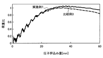
- FIG. It is a graph which shows the relationship between the indenter pushing amount and input load in Example 2 and Comparative Example 1. It is a graph which shows the relationship between the indenter pushing amount and input load in Example 7 and Comparative Example 3. Is a graph showing the ratio of the length L 1 and the reinforcing member mounting surface of the vehicle front-rear direction length L 2, a relationship between maximum load ratio of the conventional underrun protector.
- the vehicle outer side in the vehicle front-rear direction means, for example, the “front side” when the vehicle end structure is provided in front of the vehicle. When it is provided behind the vehicle, it means “rear side”.
- Vehicle inside in the vehicle longitudinal direction means the opposite side of “vehicle outside in the vehicle longitudinal direction”.
- horizontal and vertical are not “horizontal” and “vertical” in a strict sense, but substantially horizontal and substantially vertical are also included in the category of “horizontal” and “vertical”.
- the term “right angle” in this specification does not mean a strict right angle (90 °), and a substantially right angle is also included in the category of “right angle”.
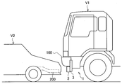
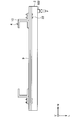
- FIG. 1 is a schematic diagram of an underrun protector according to an embodiment of the present invention.
- an underrun protector 1 including a beam 2 and a connection structure 3 is provided in a large vehicle V1.
- the underrun protector 1 according to the present embodiment is an example of an end structure of a vehicle.
- the underrun protector 1 shown in FIG. 1 is provided at the lower front part of the large vehicle V1 and is attached to a vehicle body frame (not shown) via a connection structure 3. This underrun protector 1 is provided not only in front of the large vehicle V1 but also in the rear.
- a large vehicle V1 is generally provided with a bumper 100 in front of or behind the vehicle.
- the bumper 100 can be provided at a position higher than the frame 200 of the passenger car V2. Therefore, when the large vehicle V1 and the passenger vehicle V2 collide, the bumper 100 and the frame 200 do not collide from the front, and the large vehicle V1 rides on the passenger vehicle V2. In this case, the impact energy received by the frame 200 from the large vehicle V1 cannot be absorbed, and the cabin of the passenger vehicle V2 can be deformed. Therefore, it is difficult to ensure the safety of passengers who are on the passenger car V2.
- the underrun protector 1 is provided in accordance with a height similar to that of the frame 200 of the passenger car V2. Then, when the large vehicle V1 and the passenger vehicle V2 collide in the vehicle front-rear direction, the underrun protector 1 collides with the frame 200. As a result, the passenger car V2 does not sink into the lower part of the large vehicle V1, and the collision energy received by the frame 200 from the large vehicle V1 can be absorbed. Therefore, it is possible to ensure the safety of passengers who are on the passenger car V2.
- Such an under-run protector is required to exhibit the collision energy absorption mechanism of the passenger car V2 while preventing the passenger car V2 from entering. That is, the underrun protector 1 is required to have a load-bearing performance for generating a reaction force for flipping off the passenger car V2 that collided with the large vehicle V1 rather than an effect of absorbing the collision energy generated when the underrun protector 1 collides with the passenger car V2. .
- This load bearing performance is required to be at a high level regardless of the collision position of the underrun protector 1 with respect to the beam 2 in the vehicle width direction.
- the deformation mode generated in the underrun protector 1 at the time of collision differs depending on the input position of the load to the beam 2. Therefore, it is required to improve load bearing performance related to a plurality of deformation modes.
- FIG. 2 is a view for explaining the load input position according to the load resistance evaluation method of the underrun protector.
- the method for evaluating the load bearing performance of the underrun protector (load bearing evaluation method) is based on the mounting position P1 of the beam 2 or the mounting position P1 of the connection structure 3 mounted on the vehicle body frame 20. This is a method for evaluating the maximum input load obtained in accordance with the input of the load F to the position P2 outside the width direction W.
- the underrun protector In order to sufficiently obtain the load-bearing performance of the underrun protector, it is required to correspond to the deformation mode of the beam 2 caused by the input of the load to each collision position as described above. For example, when the load F is applied to the attachment position P1, the cross section of the beam 2 may be crushed near the attachment position P1. In order to suppress the collapse of the cross section of the beam 2 at the attachment position P1, it is required to suppress the out-of-plane deformation of the beam 2. Further, when the load F is applied to the position P2, the beam 2 may be bent in the vicinity of the position P2. In order to avoid the bending of the beam 2 in the vicinity of the position P2, it is required to suppress the bending of the beam 2.
- the performance of the underrun protector as a product depends on the superiority or inferiority of the load bearing performance at the mounting positions P1 and P2. Therefore, the under-run protector excellent in load bearing performance is an under-run protector in which the maximum input load at the attachment position P1 and the position P2 is at a high level.
- FIG. 3 is a cross-sectional view showing a schematic configuration of an example of a conventional underrun protector 50.
- the conventional underrun protector 50 includes a beam 51 and a bracket 52.
- the bracket 52 is attached to a vehicle frame (not shown), and the beam 51 is attached to the bracket 52 so as to be outside the vehicle in the vehicle front-rear direction.
- the beam 51 when a load F is input to the beam collision surface, the beam 51 is deformed as shown by a broken line in FIG. At this time, for example, at the position P1 in FIG. 2, the cross section of the beam 51 is crushed. Further, when such deformation occurs at the position P2 in FIG. 2, the anti-collision surface of the beam 51 and the bracket 52 are deformed so as to bend inward of the beam 51 in the vicinity of the fastening portion between the beam 51 and the bracket 52. End up.
- the underrun protector shown in the description of each embodiment below was invented.
- the underrun protector shown in the present embodiment can improve the load bearing performance as compared with the conventional case at any collision position.
- the underrun protector according to each embodiment will be described.
- the underrun protector is an example of an end structure of a vehicle, but the present invention is not limited to such an example.
- an obstacle device for preventing an object such as a passenger car from being involved in a railway vehicle is also an example of the end structure of the vehicle according to the present invention.
- an underrun protector will be described.
- the end structure of the vehicle according to the present invention can be applied to other vehicles and machines capable of traveling.
- Other vehicles and self-propelled machines include, for example, two-wheeled vehicles, large vehicles such as buses or towing vehicles, trailers, railway vehicles, construction machinery, mining machinery, agricultural machinery, general machinery, and ships.
- each member which comprises the edge part structure of the vehicle which concerns on this invention may be metal plates, such as aluminum, titanium, or stainless steel other than a steel plate.
- the material of the material forming each member may be an alloy, a composite material composed of a metal and a resin, carbon fiber, or the like.
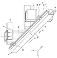
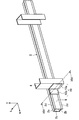
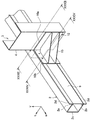
- FIG. 4 is a perspective view showing a schematic configuration of an example of the underrun protector 1 according to the first embodiment of the present invention.
- the underrun protector 1 according to the present embodiment includes a beam 2 extending in the vehicle width direction W and a connection structure 3 for connecting the beam 2 to the vehicle body frame 20.
- the connection structure 3 according to the present embodiment is, for example, a stay 4.
- the connection structure 3 may be a bracket attached to the stay.
- the bracket is also an example of a beam mounting member in other embodiments.
- Such a connection structure 3 is provided in a pair of left and right at least in front of or behind the vehicle.
- the beam 2 is provided so as to bridge a pair of left and right connection structures 3.
- the material of the material for forming such a beam 2 is not limited to steel as described above, and may be a composite material composed of various metals, alloys, metals and resins, carbon fiber, or the like. Since the beam 2 is required to have load bearing performance, it is preferably formed of a material having high strength.
- the pair of stays 4 are formed so as to extend in the vertical direction V, and have a U-shaped portion in plan view and a protruding portion 6 that protrudes inward of the beam 2. Further, the pair of stays 4 are arranged with a space therebetween such that the opening surfaces 4a face each other in the vehicle width direction W.
- a frame mounting plate 5 is provided on a part of the opening surface 4a of the pair of stays 4 so as to cover the opening.
- the frame mounting plate 5 is welded to the stay 4.
- Bolt holes 21 are formed in the frame mounting plate 5.
- the frame mounting plate 5 is bolted to the vehicle body frame 20 through the bolt holes 21. Thereby, the stay 4 is fixed to the vehicle body frame 20.
- the connection structure 3 includes a stay 4 and a frame mounting plate 5.
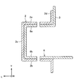
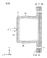
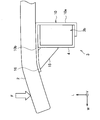
- FIG. 5 is a cross-sectional view of the underrun protector 1 according to the present embodiment taken along the line VV shown in FIG.
- the beam 2 according to the present embodiment includes a first upper surface portion 2a and a first lower surface portion 2b that face each other and a first upper surface portion 2a in a cross-sectional view perpendicular to the vehicle width direction W. And a first side surface portion 2c connecting one end of the first lower surface portion 2b.
- the first upper surface portion 2a and the first lower surface portion 2b are provided so as to be horizontal.
- the first side surface portion 2c is formed perpendicular to the first upper surface portion 2a and the first lower surface portion 2b, and has a vertical surface. Further, at the other end of the first upper surface portion 2a and the first lower surface portion 2b (one end on the side where the first side surface portion 2c is not provided), a pair of first protrusions projecting outward in the vertical direction V.
- the flange portion 2d is provided. Specifically, each of the first flange portions 2d protrudes upward in the vertical direction V at the other end of the first upper surface portion 2a, and protrudes downward in the vertical direction V at the first lower surface portion 2b. It is formed as follows. That is, the beam 2 according to the present embodiment has a so-called hat shape in a cross-sectional view perpendicular to the vehicle width direction W.
- the beam 2 according to the present embodiment has a so-called hat shape in a cross-sectional view perpendicular to the vehicle width direction W. Further, as shown in FIG. 5, a bolt hole 8 is formed in the central portion of the first upper surface portion 2a and the first lower surface portion 2b of the beam 2.
- the protruding portion 6 of the stay 4 faces the protruding upper surface portion 6 a formed so as to face the first upper surface portion 2 a and the first lower surface portion 2 b. It has a projecting lower surface portion 6b formed on the surface.
- the tip of the protruding portion 6 is close to the first side surface portion 2c.
- the first upper surface portion 2a and the protruding upper surface portion 6a are in contact with each other, and the first lower surface portion 2b and the protruding lower surface portion 6b are in contact with each other.
- bolt holes 7 are formed in the central portions of the projecting upper surface portion 6a and the projecting lower surface portion 6b, respectively.
- the protrusion 6 is fixed by the bolt 22 through the first upper surface 2 a and the first lower surface 2 b, the bolt hole 7 and the bolt hole 8. As a result, the beam 2 is attached to the vehicle body frame 20 via the stay 4.
- the underrun protector 1 is configured as described above.
- the protruding portion 6 is disposed inward of the beam 2 having an open cross section, and is fixed to the first upper surface portion 2a and the first lower surface portion 2b.
- the load F applied by the collision is transmitted in the in-plane direction as a shearing force from the first upper surface portion 2a and the first lower surface portion 2b to the protruding portion 6.
- the load applied to the first side surface portion 2c of the beam 2 is transmitted to the stay 4 via the first upper surface portion 2a and the first lower surface portion 2b, so that the load applied to the first side surface portion 2c. Decrease.
- the maximum load value in the load resistance evaluation test can be made larger than before, and the load resistance performance of the underrun protector can be improved. That is, it is possible to improve load bearing performance against a load input to the collision surface of the beam 2 (the surface on the vehicle outer side of the first side surface portion 6c) at the mounting position P1 of the beam 2 shown in FIG.
- the beam 2 has a pair of first flange portions 2d.
- the anti-load input ends of the first upper surface portion 2a and the first lower surface portion 2b in the vicinity of the load input point of the beam 2 are substantially tensile deformed. Therefore, when the beam 2 that does not have the first flange portion 2d is formed of a high-tensile material having high strength and low ductility, the end portion is at least one of the first upper surface portion 2a and the first lower surface portion 2b. Since the breakage occurs, the effect of improving the load bearing performance may be lower than expected. For this reason, the first flange portion 2 d is formed on the beam 2, whereby the above-described end portion breakage can be suppressed.
- the present invention is not limited to such an example.
- the shape of the stay 4 is not limited to the example described in the above embodiment.
- the tip of the protrusion 6 of the stay 4 is preferably close to the first side surface 2c of the beam 2 as described above.
- the position or shape of the tip of the protrusion 6 inside the beam 2 may be appropriately changed according to the required load bearing performance, the beam shape, and the like.
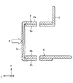
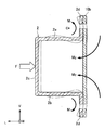
- FIG. 6 is a cross-sectional view showing a schematic configuration of a first modification of the underrun protector 1 according to the present embodiment.
- a protruding side surface portion 6c that connects the tips of the protruding upper surface portion 6a and the protruding lower surface portion 6b may be provided.
- the protruding side surface portion 6c may be provided at a position where it comes into contact with the inner surface of the first side surface portion 2c.
- the load bearing performance can be further improved.
- the beam 2 has the pair of first flange portions 2d.
- the beam 2 may not have the first flange portion 2d.
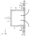
- FIG. 7 is a cross-sectional view showing a schematic configuration of a second modification of the underrun protector 1 according to the present embodiment. Even in this case, the deformation of the beam 2 can be suppressed to some extent, and the load bearing performance as an underrun protector can be improved.
- the beam 2 in which the first flange portion 2d is not formed is formed of a high-tensile material having high strength and low ductility, at least one of the first upper surface portion 2a and the first lower surface portion 2b.
- the end portion breakage occurs, so that the effect of improving the load bearing performance may be lower than expected. Therefore, from the viewpoint of suppressing the end break as described above, it is preferable that the first flange portion 2d is formed in each of the first upper surface portion 2a and the first lower surface portion 2b.
- the first upper surface portion 2a and the projecting upper surface portion 6a and the first lower surface portion 2b and the projecting lower surface portion 6b are fixed with the bolts 22, but the bolt holes 7 and the bolt holes 8
- the position is not limited to the example described in the above embodiment.
- both parts may be fixed at other positions.
- you may fix both components by welding, for example instead of bolt fixation.
- it becomes easy to replace only the damaged beam 2 by itself using a bolt the maintainability is improved.
- the protrusion part 6 is formed so that the 1st upper surface part 2a and the 1st lower surface part 2b may be contacted, the protrusion part 6, the 1st upper surface part 2a, and the 1st lower surface part 2b may not contact.
- the protruding portion 6 only needs to be fixed to the first upper surface portion 2a and the first lower surface portion 2b.
- the insertion length of the protrusion 6 from the opening of the beam 2 to the inside of the beam 2 is not particularly limited.
- the tip of the protruding portion 6 does not necessarily have to contact the first side surface portion 2c.
- the insertion length of the protruding portion 6 is short, out-of-plane deformation may occur at the time of inputting a load in at least one of the first upper surface portion 2a and the first lower surface portion 2b. Therefore, it is preferable that the insertion length of the protrusion 6 is as large as possible.
- the stay 4 is provided so as to be in contact with the first flange portion 2d of the beam 2, but the stay 4 and the first flange portion 2d are not necessarily in contact with each other.
- the load is transmitted from the first flange portion 2d to the stay 4 when a load is input. Thereby, since the load transmitted to the stay 4 increases, the load bearing performance can be improved.
- the stay 4 is composed of one part, but it may be an assembly composed of a plurality of parts.
- the structure of the stay 4 is not particularly limited as long as the stay 4 forms a protruding portion 6 that can be disposed inside the beam 2.
- the underrun protector 1 according to the first embodiment of the present invention has been described above.
- FIG. 8 is a perspective view showing a schematic configuration of the underrun protector 1 according to the second embodiment of the present invention. Since the functions of the beam 2, the stay 4, the frame mounting plate 5, and the vehicle body frame 20, which are basic components of the underrun protector 1, are the same as those in the first embodiment of the present invention, the description thereof is omitted. To do. Unlike the first embodiment of the present invention, the stay 4 according to the present embodiment does not have the protruding portion 6 and is formed to extend in the vertical direction V.
- L-shaped brackets 10 are provided on the surfaces of the pair of stays 4 facing the opening surfaces 4a.
- the bracket 10 includes a flat stay mounting portion 10a and a flat beam mounting portion 10b perpendicular to the stay mounting portion 10a.
- the stay mounting portion 10 a is fixed to the side surface of the stay 4.
- the beam mounting portion 10b is fixed in such a direction as to contact the back surface (anti-collision surface) of the beam 2.
- the bracket 10 is an example of a beam attachment member and is a part of the connection structure 3.
- FIG. 9 is a cross-sectional view of the underrun protector 1 according to the present embodiment taken along the line IX-IX shown in FIG.
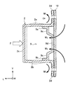
- a first reinforcing member 9 that covers all or part of the back surface of the beam 2 is provided between the beam 2 and the bracket 10.
- a closed cross section is formed by the beam 2 and the first reinforcing member 9 in a cross-sectional view perpendicular to the vehicle width direction W.
- the first reinforcing member 9 is formed in a rectangular shape so as to extend in the vehicle width direction W.
- FIG. 10 is a longitudinal sectional view showing the shape of the first reinforcing member of the underrun protector according to the present embodiment. As shown in FIG. 10, the beam 2, the bracket 10, and the first reinforcing member 9 are fastened by bolts (not shown) through the bolt holes 12.
- the underrun protector 1 is configured as described above.
- the beam 2 has a hat shape, and the beam 2 and the bracket 10 are fixed at the first flange portion 2d protruding outward in the vertical direction V.
- the input load F like the distal end of the first flange portion 2d is rotated in the impact surface side, a moment M 1 that the rotation center point C in the figure occurs.
- the end portion of the first reinforcing member 9 fixed to the first flange portion 2d and the end portion of the bracket 10 are also deformed so as to rotate toward the collision surface.
- Such a moment M 1 is a moment in the opposite direction to the moment M 2 that acts to bend the first reinforcing member 9 or the bracket 10 inward of the beam 2. For this reason, a mutual moment is canceled and the bending inward of the beam of the 1st reinforcement member 9 or the bracket 10 is suppressed.
- the present invention is not limited to such an example.
- the shapes of the bracket 10, the stay 4, and the first reinforcing member 9 are not limited to the examples described in the above embodiment.
- the shapes of these members are appropriately changed depending on the shape of the body frame 20 or the required performance of the underrun protector 1.
- the flat plate-like first reinforcing member 9 is provided so as to be in contact with the first flange portion 2d.
- the first reinforcing member 9 is formed inside the beam 2 (for example, the beam 2). Between the upper surface portion 2a and the lower surface portion 2b).
- the first reinforcing member 9 is provided in the opening of the beam 2 so that a closed cross section is formed by the beam 2 and the first reinforcing member 9 in a cross-sectional view perpendicular to the vehicle width direction W. It ’s fine. Thereby, load bearing performance can be improved. A modification of the first reinforcing member 9 will be described later.
- the beam 2 and the bracket 10 are fixed by the bolt 23, but the position of the bolt hole provided in these members is not limited to the example described in the above embodiment. Moreover, you may fix both components by welding instead of bolt fixation. However, since it becomes easy to replace only the damaged beam 2 by itself using a bolt, the maintainability is improved.
- FIG. 11 is a cross-sectional view showing a schematic configuration of a first modification of the underrun protector 1 according to the present embodiment. As shown in FIG. 11, even when the beam 2 is directly attached to the bracket 10, the inward bending of each member of the beam 2 can be suppressed as in the above embodiment. Therefore, the load bearing performance as an underrun protector can be improved.
- FIG. 12 is a cross-sectional view showing a schematic configuration of a second modification of the underrun protector 1 according to the present embodiment. Even in a configuration in which the beam 2 is directly attached to the stay 4, the inward bending of each member of the beam 2 can be suppressed as in the above embodiment. Therefore, the load bearing performance as an underrun protector can be improved.
- the beam 2 has a hat shape, and the first flange portion 2d. It is preferable that the beam 2 and the connection structure 3 are fixed. Thereby, the load bearing performance as an underrun protector can be improved. However, the load resistance performance can be further improved by further providing the first reinforcing member 9. Therefore, it is preferable that the first reinforcing member 9 is provided in the underrun protector 1.
- FIG. 13 and FIG. 14 are a perspective view showing a schematic configuration of a third modification of the underrun protector 1 according to the present embodiment, and a cross-sectional view taken along the line XIV-XIV.
- the first reinforcing member 9 according to the present modification includes a first reinforcing member upper surface portion 9 a and a first reinforcing member lower surface portion 9 b that face each other in a cross-sectional view perpendicular to the vehicle width direction W. And a U-shaped cross section having a first reinforcing member side surface portion 9c connecting one end of the first reinforcing member upper surface portion 9a and the first reinforcing member lower surface portion 9b.
- the first reinforcing member upper surface portion 9a and the first reinforcing member lower surface portion 9b, and the first upper surface portion 2a and the first lower surface portion 2b are joined, for example, by welding or the like.
- the beam 2 and the first reinforcing member 9 form a closed cross section.
- the first reinforcing member side surface portion 9 c is disposed so as to be in contact with the beam mounting portion 10 b of the bracket 10.
- the first reinforcing member 9 By arranging the first reinforcing member 9 in this way, the first upper surface portion 2a and the first lower surface portion 2b are caused to act to inhibit the deformation of the first upper surface portion 2a and the first lower surface portion 2b in the vicinity of the first flange portion 2d. be able to.
- the fixing method of the 1st reinforcement member upper surface part 9a and the 1st reinforcement member lower surface part 9b, the 1st upper surface part 2a, and the 1st lower surface part 2b is not limited to welding.
- the 1st reinforcement member 9 it is preferable to arrange
- the end portions of the first reinforcing member upper surface portion 9a and the first reinforcing member lower surface portion 9b on the side where the first reinforcing member side surface portion 9c is not provided are in relation to the first reinforcing member side surface portion 9c. It is preferable to be provided outside the vehicle in the vehicle front-rear direction L.
- the first reinforcing member side portion 9c occur sectional moment M 3 that deforms inward
- the first reinforcing member upper surface portion 9a and the first reinforcement member lower surface portion 9b is an action to be deformed in the cross-sectional outer Arise. Therefore, the deformation
- the cross-sectional shape of the first reinforcing member 9 is not limited to the U-shape shown in FIGS. 13 and 14. That is, the first reinforcing member 9 includes the opposing first reinforcing member upper surface portion 9a and first reinforcing member lower surface portion 9b, and one end of the first reinforcing member upper surface portion 9a and the first reinforcing member lower surface portion 9b. A first reinforcing member side surface portion 9c for connecting the first reinforcing member upper surface portion 9a and the first upper surface portion 2a, and the first reinforcing member lower surface portion 9b and the first lower surface portion. If each 2b is fixed, the load bearing performance can be improved. For example, the same effect can be obtained even if the first reinforcing member side surface portion 9c has a recess (not shown).
- FIG. 15 is a cross-sectional view showing a schematic configuration of a fourth modification of the underrun protector 1 according to the present embodiment. As shown in FIG.
- the first reinforcing member 9 may be further provided with a first reinforcing member convex portion 9 d at the central portion of the first reinforcing member side surface portion 9 c.
- the first reinforcing member convex portion 9d abuts against the beam mounting portion 10b, so that an effect of suppressing the out-of-plane deformation of the first reinforcing member 9 and the beam mounting portion 10b can be obtained.
- the first reinforcing member upper surface portion 9a and the first reinforcing member is preferably disposed near the first flange portion 2d.
- the beam mounting portion 10b can be deformed into a wave shape. This induces out-of-plane deformation, which can be an impediment to improvement in load bearing performance. Accordingly, the present inventors have further intensively studied the shape of the beam mounting portion 10b, and have developed the under-run protector 1 described below.
- 16 and 17 are a perspective view showing a schematic configuration of a fifth modification of the underrun protector 1 according to the present embodiment, and a cross-sectional view taken along the line XVII-XVII.
- the shape of the beam attachment portion 10b in a cross-sectional view perpendicular to the vehicle width direction W is a substantially hat-shaped cross-sectional shape.
- the beam attachment portion 10b is connected to the second upper surface portion 10c and the second lower surface portion 10d, and the second upper surface portion 10c and one end of the second lower surface portion 10d.
- the second upper surface portion 10 c and the second lower surface portion 10 d are formed so as to be inclined with respect to the horizontal plane. The inclination angle of the lower surface portion 10d with respect to the horizontal plane is appropriately changed according to required load bearing performance and surrounding margin.
- the beam mounting portion 10 b has a substantially hat-shaped cross section, so that the cross-sectional rigidity and strength are increased as compared with the plate-shaped beam mounting portion. Therefore, the wavy out-of-plane deformation that occurs in the bracket 10 can be inhibited. Further, as shown in FIG. 17, a moment M 2 generated in the beam attachment portion 10b, by the moment M 1 generated in the first flange portion 2d are opposite, obtain the effect of inhibiting the deformation of each other be able to. Thereby, it is possible to improve load bearing performance.
- the second side surface portion 6e is located on the vehicle interior side with respect to the first flange portion 2d relative to the first flange portion 2d. It is desirable to be located in the direction L).
- the cross-sectional area of the closed cross section formed by the beam 2 and the bracket 10 in a cross-sectional view perpendicular to the vehicle width direction W can be increased. Thereby, since the bending rigidity and intensity
- the stay attachment portion 10a and the beam attachment portion 10b may be separate members. However, in that case, the cost for assembling the stay attaching portion 10a and the beam attaching portion 10b increases. Therefore, it is preferable that the stay attaching portion 10a and the beam attaching portion 10b are formed as an integral bracket 10.
- FIG. 18 is a cross-sectional view showing a schematic configuration of a sixth modification of the underrun protector 1 according to the present embodiment. As shown in FIG. 18, the first reinforcing member side surface portion 9c is directed toward the second side surface portion 6e of the beam attachment portion 10b (the vehicle inner side in the vehicle front-rear direction L with respect to the first flange portion 2d). It is preferable that a protruding first reinforcing member convex portion 9d is provided.
- the first reinforcing member 9 includes a first reinforcing member upper surface portion 9a and a first reinforcing member lower surface portion 9b, and a first reinforcing member upper surface portion 9a that face each other in a cross-sectional view perpendicular to the vehicle width direction W. And a first reinforcing member side surface portion 9c connecting one end of the first reinforcing member lower surface portion 9b, and a part of the first reinforcing member side surface portion 9c protrudes from the second side surface portion 6e. Is preferred.
- the cross section of the closed cross section formed by the beam 2 and the first reinforcing member 9 can be made large in a cross sectional view perpendicular to the vehicle width direction W.
- the bending rigidity and strength of the beam 2 can be increased, and the load bearing performance can be improved. Further, as described above, it is more preferable that a part of the first reinforcing member side surface portion 9c abuts against the second side surface portion 6e. Thereby, the out-of-plane deformation of the first reinforcing member 9 and the beam mounting portion 10b can be suppressed. Further, from the viewpoint of inhibiting the deformation of the first upper surface portion 2a and the first lower surface portion 2b to the inside of the cross section in the vicinity of the first flange portion 2d, the first reinforcing member upper surface portion 9a and the first reinforcing member The lower surface portion 9b is preferably disposed near the first flange portion 2d.
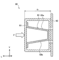
- Some conventional underrun protectors 60 are provided with a hat-shaped reinforcing member 63 as shown in FIG.
- the hat-shaped reinforcing member 63 has an upper surface portion 63a and a lower surface portion 63b facing each other, and is disposed so as to bridge the collision surface and the anti-collision surface of the beam 61 having a rectangular cross section. Thereby, the reinforcement which suppresses a deformation
- a reinforcing member as shown in FIG. 19 may be provided inside the closed cross section formed by the beam 2 and the beam mounting portion 10b.
- the second reinforcing member 90 includes a second reinforcing member upper surface portion 90 a and a second reinforcing member lower surface portion 90 b that are opposed to each other in a cross-sectional view perpendicular to the vehicle width direction W, and a second reinforcing member 90.
- a second reinforcing member side surface portion 90c connecting one end of the reinforcing member upper surface portion 90a and the second reinforcing member lower surface portion 90b, and the other end of the second reinforcing member upper surface portion 90a and the second reinforcing member lower surface portion 90b ( One end of the side where the second reinforcing member side face portion 90c is not provided) has a pair of second reinforcing member flange portions 90e formed so as to protrude outward in the vertical direction V.
- the second reinforcing member side surface portion 90c of the second reinforcing member 90 is located on the vehicle inner side (the vehicle inner side in the vehicle front-rear direction L with respect to the first flange portion 2d) than the open section of the beam 2.
- the second reinforcing member flange portion 90e and the first side surface portion 2c are fixed by, for example, welding.
- the fixing method of the 2nd reinforcement member flange part 90e and the 1st side part 2c is not limited to welding.
- the second reinforcing member upper surface portion 90a and the second reinforcing member lower surface portion 90b are formed so as to be inclined with respect to the horizontal plane. The inclination angle of the second reinforcing member lower surface portion 90b with respect to the horizontal plane is appropriately changed according to required load bearing performance, beam shape, and the like.
- the second reinforcing member side surface portion 90c of the second reinforcing member 90 is disposed so as to contact the second side surface portion 10e of the beam mounting portion 10b. It is not necessary to touch.
- a gap may be provided between the second reinforcing member side surface portion 90c and the second side surface portion 6e within a range in which reinforcement that supports the collision surface is possible.
- the second reinforcing member side surface portion 90c abuts against the second side surface portion 6e. Is preferred.
- the stay 4 and the second reinforcing member 90 are provided. It is necessary to avoid interference.
- the stay 4 may be provided with a recess (not shown) for avoiding interference with the second reinforcing member 90, or may be provided with a notch (not shown).
- a recess formed by a member different from the stay 4 may be provided in the stay 4. However, when the notch is provided, the strength of the stay 4 can be reduced.
- the concave portion of the stay 4 is formed by a separate member, the assembly of the stay 4 and the concave portion is necessary, which increases the cost. Therefore, when the recess is provided in the stay 4, it is preferable that the stay 4 and the recess are integrally formed.
- the vehicle protrusion distance D 2 in the longitudinal direction L which starts beam mounting surface 10b of the first side surface portion 2c in the form (referred to as the present embodiment) shown in FIG. 21 is assumed to be the same in.
- the cross-sectional view perpendicular to the vehicle width direction W the cross-sectional area of the closed cross section formed by being surrounded by the beam 2 and the beam mounting surface 10b is larger in the present embodiment than in the conventional embodiment. That is, when the position of the first side surface portion 2c in the vehicle front-rear direction L is restricted, the area of the closed cross section formed by being surrounded by the beam 2 and the beam mounting surface 10b is increased without inhibiting the restriction. be able to.
- FIG. 22 is a cross-sectional view illustrating a schematic configuration of an eighth modification of the underrun protector 1 according to the present embodiment.
- protrusion distance D 2 of the present embodiment is shorter than the protrusion distance D 1 of the conventional form. That is, the size of the underrun protector becomes compact compared to the conventional one while ensuring load bearing performance. Therefore, weight reduction can be achieved and the degree of freedom in vehicle design can be improved.
- the underrun protector 1 according to the second embodiment of the present invention has been described above.
- the beam 2 has a hat shape, and the beam 2 is connected so that the first side surface portion 2c is positioned on the vehicle outer side in the vehicle front-rear direction L. Fixed to the body 3. That is, the 1st side part 2c becomes a collision surface.
- the beam 2 may be fixed to the connection structure 3.
- the beam 2 may be fixed to the connection structure 3 by bonding the first flange portion 2d and the connection structure 3.
- the beam 2 and the connection structure 3 may be fixed by the respective joints in the first embodiment or the second embodiment.
- connection structure 3 is disposed inside the beam 2 as in the first embodiment. Thereby, the cross-sectional crushing in the said attachment position can be suppressed. Further, the connection structure 3 contacts the first flange portion 2d of the beam 2 as in the second embodiment in order to improve the load resistance at the position P2 outside the vehicle width direction W from the mounting position of the beam 2.
- the first embodiment or the second embodiment, or both can be selected according to the collision mode in which the load resistance is to be improved. That is, the desired load bearing performance of the underrun protector 1 can be improved.
- the present invention is not limited to the example described in the above embodiment.
- the first upper surface portion 2a and the first lower surface portion 2b are horizontal, but at least one of the first upper surface portion 2a and the first lower surface portion 2b is not in a horizontal state. May be.
- the first upper surface portion so that the angles formed by the first side surface portion 2c, the first upper surface portion 2a, and the first lower surface portion 2b are obtuse angles, respectively. 2a and the 1st lower surface part 2b may be provided in the state which inclined. Even in this case, the load bearing performance can be improved as compared with the under-run protector provided with the rectangular beam.
- FIG. 23 is a diagram illustrating an example of a state of deformation of the underrun protector 71 when a load is input to the conventional underrun protector 71.
- the conventional underrun protector 71 includes, for example, a connection structure 72 (for example, a stay and a bracket) attached to the vehicle frame, and extends in the vehicle width direction W, and is attached to the beam attachment surface of the connection structure 72.
- a beam 73 to be attached and a reinforcing member 74 provided so as to bridge between the connection structure 72 and the beam 73 are provided. By providing this reinforcing member 74, the load bearing performance has been improved.
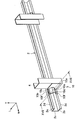
- FIG. 24 is a perspective view showing a schematic configuration of the underrun protector 1 according to the third embodiment of the present invention.
- the underrun protector 1 according to the present embodiment includes a beam 2 having a hat-shaped cross section extending in the vehicle width direction W, and a connection structure 3 for attaching the beam 2 to the vehicle body frame 20. .
- the beam 2 is fixed to the vehicle body frame 20 via the connection structure 3.
- the connection structure 3 in the present embodiment includes a stay 4 formed to extend in the vertical direction V, an L-shaped bracket 10 provided between the beam 2 and the stay 4, a third reinforcing member 15, and the like.
- the beam 2 has a single closed cross-sectional shape in a cross-sectional view perpendicular to the vehicle width direction W, but the beam 2 may have a hat-shaped cross section.
- FIG. 25 is a cross-sectional view of the underrun protector 1 according to the present embodiment taken along the line XXV-XXV shown in FIG.
- the stay 4 is formed in a U shape in plan view.
- the opening of the stay 4 is provided so as to face the inner side in the vehicle width direction W.
- a part of the opening of the stay 4 is covered with a body frame side surface 10 a (corresponding to the stay mounting surface 10 a) of the bracket 10, and the tip of the body 10 side surface 10 a of the bracket 10 is The outer side of the side wall 4c is fixed, for example, by welding.
- a surface (hereinafter referred to as “beam mounting surface 10b”) to which the beam 2 which is a surface perpendicular to the surface 10a on the body frame side of the bracket 10 is fixed to the back surface 4b of the stay 4 by welding, for example. Yes.
- the bracket 10 is fixed to the stay 4, and a portion (hereinafter referred to as “closed cross-section portion 3 b”) whose horizontal cross-sectional shape is a closed cross section is formed by the body frame side surface 10 a of the bracket 10 and the stay 4.
- the bracket 10 may be fixed to the side wall portion 4 c of the stay 4. In this case, the closed cross section 3 b is not formed by the bracket 10 and the stay 4.
- a frame mounting plate 5 to which a vehicle body frame (not shown) is mounted is provided on the upper portion of the stay 4.
- the frame mounting plate 5 is fixed to the stay 4 by, for example, welding.
- the frame mounting plate 5 is fastened by a vehicle body frame and bolts. Thereby, the connection structure 3 is fixed to the vehicle body frame.
- a bent portion 16 that is bent rearward in the vehicle front-rear direction L is provided at the front end portion of the beam attachment surface 10b of the bracket 10 on the outer side in the vehicle width direction W.
- the in-plane curvature radius of the bent portion 16 is preferably 50 to 200 mm. When the radius of curvature is less than 50 mm, the beam 2 is deformed with a small curvature, so stress concentration on the beam 2 is difficult to be relaxed, and it is difficult to obtain an effect of suppressing the bending of the beam 2.
- the beam 2 is stressed at the edge of the tip of the beam mounting surface 10 b. Concentrate.
- the beam mounting surface 10b and the beam 2 are fastened by, for example, bolts. Thereby, the beam 2 is fixed to the connection structure 3.
- the third reinforcing member 15 is provided so as to span between the beam mounting surface 10b of the bracket 10 and the back surface 4b of the stay 4.
- the third reinforcing member 15 in the present embodiment is a triangular plate member, and is welded to the back surface 4 b of the stay 4 (hereinafter referred to as “reinforcing member mounting surface”) and the inner surface of the bracket 10.
- Two third reinforcing members 15 are arranged along the vertical direction V.
- the third reinforcing member 15 is formed so as to follow the bent portion 16 in the periphery of the outer end portion of the beam mounting surface 10b in the vehicle width direction W. That is, the shape of the tip portion outside the third reinforcing member 15 in the vehicle width direction W has a radius of curvature equivalent to the radius of curvature R of the bent portion 16.
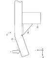
- the underrun protector 1 is configured as described above. According to such a configuration, as shown in FIG. 26, when a load is input to the beam 2, the beam 2 is bent and deformed along the curved surface portion of the bent portion 16. Thereby, it can avoid that stress concentrates on the beam 2 locally in the front-end
- each member of the connection structure 3 that connects the beam 2 and the body frame is not limited to that described in the above embodiment.
- the stay 4 formed in a U shape in plan view may be arranged so that the opening thereof faces the outside in the vehicle width direction W.
- a flat plate or the like that covers the opening of the stay 4 may be further provided, and the third reinforcing member 15 may be provided so as to bridge the beam attachment surface 10b and the flat plate.
- the body frame side surface 10a of the bracket 10 is welded in accordance with the opening of the stay 4 facing outward in the vehicle width direction W, and the body frame side surface 10a of the bracket 10 and the beam mounting surface 10b are bridged.
- a third reinforcing member 15 may be provided.
- a plate-like member extending in the vertical direction V may be used instead of the stay 4.
- the surface 10a on the frame mounting side of the bracket 10 is formed in a U shape in plan view, the surface 10a on the frame mounting side is welded to the plate member, and the plate member and the beam mounting surface 10b are connected.
- the 3rd reinforcement member 15 may be provided so that it may span.
- connection structure 3 that connects the beam 2 and the vehicle body frame includes a structure body portion (for example, a stay 4) provided so as to extend in the vertical direction V, and a frame attachment portion to which the vehicle body frame is attached (for example, a frame mounting plate 5) and a beam mounting member (for example, a bracket 10) to which a beam is mounted are provided, and the beam mounting member has a beam mounting surface to which the beam is mounted and a surface perpendicular to the beam mounting surface in plan view.
- FIG. 27 is a perspective view showing a schematic configuration of a first modification of the underrun protector 1 according to the present embodiment.
- the reinforcing plate 17 includes a distal end portion 15a on the rear side in the vehicle front-rear direction L of the distal end portion 15a or the distal end portion 15b of the third reinforcing member 15 (the distal end portion on the closed section 3b side).
- the reinforcement board 17 is provided so that it may extend from the back side front-end
- Such an effect can be enjoyed when a plurality of third reinforcing members 15 are provided. That is, the reinforcing plate 17 is aligned with the position of the rear end portion 15a in the vehicle front-rear direction L so that the third reinforcing member 15 is located on the uppermost side from the rear end portion 15a of the third reinforcing member 15 positioned on the lowermost side. What is necessary is just to be provided so that it may extend to the back side front-end
- the third reinforcing member 15 is provided so as to satisfy the following formula (1).
- the lower limit of 0.8 shown in the above formula (1) is a value found from test results conducted by the present inventors under a plurality of conditions, as will be shown in Examples described later.
- FIG. 29 is a perspective view showing a schematic configuration of a second modified example of the underrun protector 1 according to the present embodiment.
- FIG. 30 is a diagram illustrating an example of a state of deformation of the under-run protector 1 when a load is input to the under-run protector 1 according to the present modification.
- the closed cross-section 3b is interposed via the third reinforcing member 15. Can be widely distributed to the side wall portion 4c of the stay. Therefore, as shown in FIG. 30, the out-of-plane deformation to the inside of the closed section 3b can be suppressed. Therefore, the load bearing performance of the underrun protector can be further improved.
- FIG. 31 is a perspective view showing a schematic configuration of a third modification of the underrun protector 1 according to the present embodiment.
- the partition member 18 may be provided so as to fill the space inside the closed cross-sectional portion 3 b in the horizontal cross-sectional view of the closed cross-sectional portion 3 b of the connection structure 3.
- the partition member 18 is a flat plate member, for example.
- the material of the partition member 18 is not particularly limited.
- the material of the partition member 18 may be metal, plastic, or a composite member.
- the partition member 18 is arranged according to the installation height of the third reinforcing member 15.
- the partition member 18 By providing the partition member 18 inward of the closed cross-section portion 3b in this way, the partition member 18 inhibits the out-of-plane deformation of the stay 4, so that the deformation of the connection structure 3 inward of the closed cross-section portion 3b is prevented. Can be suppressed. Therefore, the load bearing performance can be further improved. In addition, in order to achieve weight reduction, a part of the area may be thinned in a region inside the peripheral end portion of the partition member 18.
- the underrun protector 1 according to the third embodiment of the present invention has been described above.
- the underrun protector 1 which concerns on the 4th Embodiment of this invention is demonstrated.
- the underrun protector 1 according to the present embodiment has a configuration in which characteristic constituent elements (protrusions and reinforcing members) of the underrun protector 1 according to the first to third embodiments of the present invention are combined. Have.
- FIG. 32 is a perspective view showing a schematic configuration of the underrun protector 1 according to the fourth embodiment of the present invention.
- FIG. 33 is a cross-sectional view of the underrun protector 1 according to the present embodiment taken along the line XXXIII-XXXIII shown in FIG. 34 is a cross-sectional view of the underrun protector 1 according to the present embodiment taken along the line XXXIV-XXXIV shown in FIG.
- the functions of the beam 2, the stay 4, the frame mounting plate 5, the bracket 10, the third reinforcing member 15, and the vehicle body frame 20, which are basic components of the underrun protector 1, are described in the first aspect of the present invention. Since this is the same as each of the embodiments to the third embodiment, the description is omitted.
- the stay 4 according to the present embodiment has a protruding portion 6.
- the protruding portion 6 protrudes inward of the beam 2 from the opening of the beam 2 and is fixed to the first upper surface portion 2 a and the first lower surface portion 2 b of the beam 2.
- the cross-sectional shape of the beam 2 according to this embodiment in a cross-sectional view perpendicular to the vehicle width direction W is T-shaped unlike the first embodiment of the present invention. Good.
- the stay 4 can be disposed in contact with each of the first flange portions 2 d of the beam 2. Thereby, the load transmitted to the stay 4 from the 1st flange part 2d becomes large. Therefore, the load resistance performance against the load applied to the mounting position P1 of the beam 2 shown in FIG. 2 is improved.
- a first reinforcing member 9 is provided in the opening of the beam 2 according to the present embodiment.
- the first reinforcing member upper surface portion 9a and the first reinforcing member lower surface portion 9b of the first reinforcing member 9, and the first upper surface portion 2a and the first lower surface portion 2b are joined together by welding or the like, for example. Yes.
- the beam 2 and the first reinforcing member 9 form a closed cross section. Thereby, the deformation
- a third reinforcing member 15 is bridged between the stay mounting surface 10a and the beam mounting surface 10b of the bracket 10 according to the present embodiment.
- a bent portion 16 that is bent rearward in the vehicle front-rear direction L is provided at a front end portion in the vehicle width direction W on the beam mounting surface 10 b of the bracket 10.
- the underrun protector 1 according to the present embodiment is configured as described above.
- the underrun protector 1 according to this embodiment includes a protrusion 6 shown in the first embodiment of the present invention, the first reinforcing member 9 shown in the second embodiment of the present invention, and the present invention. It has the bracket 10 and the 3rd reinforcement member 15 which were shown in 3rd Embodiment. Accordingly, it is possible to improve the load bearing performance with respect to each of the load applied to the mounting position P1 of the beam 2 shown in FIG. 2 and the position P2 outside the mounting position P1 in the vehicle width direction W. That is, it is possible to improve the overall load bearing performance of the underrun protector 1.
- each component according to the first to third embodiments of the present invention is included in the underrun protector 1, but the present invention is not limited to such an example.
- each component shown in the first embodiment and the second embodiment of the present invention may be incorporated in the underrun protector 1.
- each component shown in the first embodiment and the third embodiment of the present invention may be incorporated in the underrun protector 1.
- each component shown in the second embodiment and the third embodiment of the present invention may be incorporated in the underrun protector 1.
- various modified examples shown in the respective embodiments can be incorporated into the underrun protector 1 according to other embodiments.
- Each component shown in each embodiment may be appropriately incorporated in the underrun protector 1 as long as no structural interference occurs.
- the underrun protector 1 according to the fourth embodiment of the present invention has been described above.
- Example 1 A load resistance evaluation test was performed using the underrun protector according to the first embodiment of the present invention and the underrun protector having a conventional structure.
- a conventional under-run protector (Comparative Example 1) has a configuration in which the stay protrusion is removed from the configuration shown in FIG. 4 and the beam has a rectangular cross-sectional shape.
- the underrun protector according to the second embodiment of the present invention is an underrun protector (Example 1) having the configuration shown in FIG.
- the beam is made of high-tensile steel having a tensile strength of 780 MPa, and the stay is made of a thick material having a tensile strength of 540 MPa.
- FIG. 35 is a diagram for explaining a test method of a load resistance evaluation test for the underrun protector 1 according to Experimental Example 1.
- the underrun protector 1 shown in FIG. 35 is the underrun protector 1 according to the first embodiment.
- an indenter 101 is provided at the mounting position P1 of the beam 2, and a load F is applied to the indenter 101.
- the input position of the load is the same in the underrun protector according to Example 1 and Comparative Example 1.
- the indenter push-in amount and the input load were recorded. Based on this record, the load bearing performance of the underrun protectors according to Example 1 and Comparative Example 1 was evaluated.
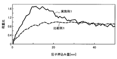
- FIG. 36 shows the relationship between the indenter pushing amount and the input load in Example 1 and Comparative Example 1.
- the “load ratio” shown in FIG. 36 represents the ratio between the recorded input load and the maximum input load obtained by the load resistance evaluation test for Comparative Example 1.
- Example 1 As shown in FIG. 36, in Comparative Example 1, the input load gradually increased as the indenter pressing amount increased. Further, in Comparative Example 1, when the indenter was pushed to some extent, the input load became almost constant. On the other hand, in Example 1, the increase in the input load became significant when the indenter pressing amount was small. In Example 1, thereafter, the input load gradually decreased.
- Table 1 shows the maximum load ratio of the underrun protector according to Example 1 to the underrun protector according to Comparative Example 1 in this load resistance evaluation test.
- the load resistance can be improved by 70% or more with respect to the underrun protector according to Comparative Example 1.
- the underrun protector according to the first embodiment of the present invention is superior to the conventional underrun protector when a load is applied to the beam mounting position. It was shown to have high load resistance.
- the underrun protector having the conventional structure is an underrun having the configuration shown in FIG. 19 in which a second reinforcing member is added to the underrun protector according to the comparative example 1 and the underrun protector 1 according to the comparative example 1. It is a protector (Comparative Example 2).
- the underrun protector according to the second embodiment of the present invention is an underrun protector having the configuration shown in FIG. 8 (Example 2), and an underrun excluding the first reinforcing member from the configuration shown in FIG.
- Run protector (Embodiment 3), underrun protector (Embodiment 4) having the configuration shown in FIG. 14, underrun protector (Embodiment 5) having the configuration shown in FIG. 17, and underrun protector having the configuration shown in FIG. Example 6).
- the beam is made of high-tensile steel having a tensile strength of 780 MPa
- the stay and the bracket are made of thick materials having a tensile strength of 540 MPa.
- the first reinforcing member and the second reinforcing member are formed of thick materials having a tensile strength of 780 MPa class.
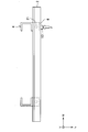
- FIG. 37 is a diagram for explaining a test method of a load resistance evaluation test for the underrun protector 1 according to Experimental Example 2.
- the underrun protector 1 shown in FIG. 37 is the underrun protector 1 according to the second embodiment.
- an indenter 102 is provided at a position P2 outside the mounting position P1 of the beam 2 in the vehicle width direction W, and a load F is applied to the indenter 102.
- the input position of the load is the same in the underrun protector according to each example and each comparative example.
- the indenter push-in amount and the input load were recorded. Based on the record, the load bearing performance of the underrun protector according to each example and each comparative example was evaluated.
- FIG. 38 shows the relationship between the indenter pushing amount and the input load in Example 2 and Comparative Example 1.
- the “load ratio” shown in FIG. 38 represents the ratio between the recorded input load and the maximum input load obtained by the load resistance evaluation test for Comparative Example 1.
- Example 2 and Comparative Example 1 As shown in FIG. 38, in both Example 2 and Comparative Example 1, as the indenter was pushed, the input load increased to a certain push amount. In Example 2 and Comparative Example 1, the input load gradually decreased thereafter. Thus, with respect to the relationship between the indenter push-in amount and the input load, the same tendency was observed in Example 2 and Comparative Example 1. On the other hand, the input maximum load value was significantly larger in Example 2 than in Comparative Example 1.
- Table 2 shows the maximum load ratio and the weight ratio of the underrun protector according to Example 2, Example 3, Example 4, and Example 5 with respect to the underrun protector according to Comparative Example 1.
- the load resistance can be improved by 30% or more compared to the underrun protector according to Comparative Example 1.
- the load resistance can be improved 5% with respect to the underrun protector which concerns on the comparative example 1.
- the weight can be reduced by about 10% compared to the underrun protector according to the first comparative example. That is, according to the underrun protector according to the third embodiment, it is possible to improve the load bearing performance while reducing the weight with respect to the conventional underrun protector.
- the load resistance can be improved by 100% or more with respect to the underrun protector according to Comparative Example 1. That is, the underrun protector according to the fourth embodiment has higher load bearing performance than the underrun protector according to the second embodiment. Therefore, the load bearing performance can be improved by providing the first reinforcing member having a U-shaped cross section on the inner side of the beam.
- the load resistance can be improved by 15% or more compared to the underrun protector according to Comparative Example 1. Furthermore, the underrun protector according to Example 5 can be reduced by about 10% compared to the underrun protector according to Comparative Example 1. Further, the underrun protector according to the fifth embodiment has the same weight as the underrun protector according to the third embodiment. However, the load resistance performance of the underrun protector according to the fifth embodiment is higher than that of the underrun protector according to the third embodiment. From this, it can be seen that the load bearing performance is further improved by making the shape of the beam mounting portion of the bracket a hat-shaped cross-sectional shape.
- the load resistance can be improved by 4% compared to the underrun protector according to Comparative Example 2. Furthermore, according to the underrun protector according to Example 6, the underrun protector according to Comparative Example 2 can be reduced in weight by about 20%. That is, if the second reinforcing member and the bracket have a hat-shaped cross section and are provided so as to support the side portions of the beam and the bracket, the weight of the conventional under-run protector can be reduced. It becomes possible to improve the load bearing performance.
- the underrun protector according to the second embodiment of the present invention is located at a position outside the beam mounting position W in the vehicle width direction W with respect to the conventional underrun protector. On the other hand, it was shown that it has excellent load resistance when a load is applied.
- the under-run protector according to the third embodiment of the present invention is an under-run protector (Example 7) having the configuration shown in FIG. 24, and a bent portion is provided at the front end portion in the vehicle width direction W of the beam mounting surface. Is provided.
- the under-run protector having a conventional structure is an under-run protector (Comparative Example 3) that does not have a bent portion at the front end portion in the vehicle width direction W of the beam mounting surface from the under-run protector shown in FIG.
- the beam is made of high-tensile steel having a tensile strength of 780 MPa, and the stay and the bracket are made of thick materials having a tensile strength of 540 MPa. Further, the third reinforcing member provided so as to bridge between the structure main body portion and the beam mounting surface in a plan view is formed of a thick material having a tensile strength of 540 MPa.
- the curvature radius of the bent portion according to the ninth embodiment is 100mm, L 1 / L 2 is 0.6.
- the load resistance evaluation test is performed by applying an indenter to the beam side surface portion at the position P2 outside the stay mounting position W in the vehicle width direction W as shown in FIG. It was broken.
- the input position of the load is the same in the underrun protector according to each example and each comparative example.
- the indenter push-in amount and the input load were recorded. Based on the record, the load bearing performance of the underrun protector according to each example and each comparative example was evaluated.
- FIG. 39 shows the relationship between the indenter pushing amount and the input load in Example 7 and Comparative Example 3.
- the maximum input load of the underrun protector according to Example 7 is larger than the maximum input load of the underrun protector according to Comparative Example 3. That is, it is possible to improve the load bearing performance of the underlamp protector by providing a bent portion at the tip of the beam mounting surface.
- the type of the structure of the underrun protector in this embodiment is a structure A in which a bent portion is provided at the outer end in the vehicle width direction W of the beam mounting surface, and the reinforcing plate shown in FIG.
- the structure B and the structure A are three types of the structure C in which the partition member shown in FIG. 31 is added.
- the shape of the third reinforcing member is the same in each structure.
- the structure A it was prepared third two types of length L 1 in the vehicle longitudinal direction L of the reinforcing member shown in FIG. 25.
- three kinds of bending radii of curvature were prepared. For these Examples 8 to 19, a load resistance evaluation test was performed. Since the test conditions are the same as in Experimental Example 3 described above, description thereof is omitted.
- Table 4 shows the parameters relating to the structure of the underrun protector according to Examples 8 to 19, and the maximum load ratio and the weight ratio of the underrun protector according to Examples 8 to 19 with respect to the underrun protector according to Comparative Example 3. Show.
- the structure B has higher load bearing performance than the structure A.
- the structure C has higher load bearing performance than the structure B. That is, according to the present embodiment, in addition to providing a bent portion at the tip of the beam mounting surface of the connection structure, the load bearing performance is improved by providing the reinforcing plate inside the closed cross section of the connection structure. I understand that Moreover, it turns out that it replaces with a reinforcement board and a load bearing performance improves further by providing a partition member inside the closed cross-section part of a connection structure. In addition, it is considered that the load bearing performance is further improved by applying both the structure B and the structure C to the underrun protector.
- the load bearing performance is further improved as the radius of curvature of the bent portion is increased. That is, when the out-of-plane deformation of the closed cross-section due to the input of load is effectively suppressed as in the structure C, the load bearing performance can be further improved by increasing the curvature radius of the bent portion.
- Figure 40 is a graph showing the ratio of the length L 2 in the vehicle longitudinal direction L of the length L 1 and the reinforcing member mounting surface, the relationship between maximum load ratio of the conventional underrun protector.
- the curvature radius of a bending part is 200 mm.
- the third reinforcing member is preferably provided so as to satisfy L 1 / L 2 ⁇ 0.8. Such knowledge was obtained for the first time by the present inventors.
- the underrun protector according to the third embodiment of the present invention is more in the vehicle width direction W than the beam mounting position with respect to the conventional underrun protector. It has been shown that it has excellent load bearing when a load is applied to the outer position.
- the under-run protector according to the fourth embodiment of the present invention is the under-run protector according to Comparative Example 1 described above.
- the underrun protector according to the fourth embodiment of the present invention is an underrun protector (Example 20) having the configuration shown in FIG.
- the beam is made of high-tensile steel having a tensile strength of 780 MPa, and the stay and the bracket are made of thick materials having a tensile strength of 540 MPa.
- the first reinforcing member is formed of a thick material having a tensile strength of 780 MPa class.
- the third reinforcing member is formed of a thick material having a tensile strength of 540 MPa class.
- the indenter In the load resistance evaluation test, in the same manner as in Experimental Examples 2 to 4, the indenter is applied to the side surface of the beam at the position P2 outside the vehicle mounting direction W from the stay mounting position shown in FIG. Was done by The input position of the load is the same in both the underrun protector according to Example 20 and Comparative Example 1.
- the indenter push-in amount and the input load were recorded. Based on the record, the load bearing performance of the underrun protectors according to Example 20 and Comparative Example 1 was evaluated. Note that the underrun protector according to the twentieth embodiment has the same configuration as the underrun protector according to the first embodiment.
- Table 5 shows the maximum load ratio of the underrun protector according to Example 20 to the underrun protector according to Comparative Example 1.
- the load resistance can be improved by 130% or more compared to the underrun protector according to Comparative Example 1. Accordingly, the first reinforcing member having a U-shaped cross section and the third reinforcing member provided so as to bridge the beam mounting surface and the reinforcing member mounting surface are combined and applied to the underlamp protector. The load performance can be remarkably improved.
- the underrun protector according to the fourth embodiment of the present invention is located at a position outside the beam mounting position W in the vehicle width direction W with respect to the conventional underrun protector.
- the load when a load was given, it was shown that it has a remarkably excellent load resistance.
Landscapes
- Engineering & Computer Science (AREA)
- Mechanical Engineering (AREA)
- Chemical & Material Sciences (AREA)
- Combustion & Propulsion (AREA)
- Transportation (AREA)
- Body Structure For Vehicles (AREA)
Abstract
Description
図1は、本発明の一実施形態に係るアンダーランプロテクターの概要図である。図1に示すように、大型車V1には、ビーム2および接続構造体3により構成されるアンダーランプロテクター1が設けられている。本実施形態に係るアンダーランプロテクター1は、車両の端部構造の一例である。図1に示すアンダーランプロテクター1は大型車V1の前方下部に設けられており、接続構造体3を介して車体フレーム(図示せず)に取り付けられている。このアンダーランプロテクター1は、大型車V1の前方のみならず、後方にも設けられる。
図4は、本発明の第1の実施形態に係るアンダーランプロテクター1の一例の概略構成を示す斜視図である。図4に示すように、本実施形態に係るアンダーランプロテクター1は、車幅方向Wに延びるビーム2と、ビーム2を車体フレーム20に接続するための接続構造体3とを含む。本実施形態に係る接続構造体3は、例えばステー4である。なお、他の実施形態においては、接続構造体3はステーに取り付けられるブラケットであってもよい。当該ブラケットは、他の実施形態においてはビーム取付部材の一例でもある。このような接続構造体3は、車両の前方または後方の少なくともいずれかに、左右一対に設けられる。ビーム2は、左右一対の接続構造体3を架け渡すように設けられる。このようなビーム2を形成する材料の材質は、上述したように鋼材に限られず、各種金属、合金、金属および樹脂により構成される複合材料、または炭素繊維等であってもよい。ビーム2には耐荷重性能が求められるので、強度の高い材料により形成されることが好ましい。
図6は、本実施形態に係るアンダーランプロテクター1の第1の変形例の概略構成を示す断面図である。図6に示すように、突出上面部6aと突出下面部6bの先端を接続する突出側面部6cが設けられてもよい。この場合、突出側面部6cは、第1の側面部2cの内側の面と当接する位置に設けられてもよい。この場合、荷重が入力された際に、第1の側面部2cの変形の抑制とともに、突出部6の面外変形(例えば、突出上面部6aまたは突出下面部6bの面外変形)の抑制が可能となる。したがって、耐荷重性能をさらに向上させることができる。
また、上記実施形態においてビーム2は一対の第1のフランジ部2dを有するとしたが、ビーム2には第1のフランジ部2dが形成されていなくてもよい。図7は、本実施形態に係るアンダーランプロテクター1の第2の変形例の概略構成を示す断面図である。この場合であっても、ビーム2の変形をある程度抑制することができ、アンダーランプロテクターとしての耐荷重性能を向上させることができる。しかし上述したように、第1のフランジ部2dが形成されていないビーム2が強度が高く延性が低いハイテン材で構成される場合、第1の上面部2aまたは第1の下面部2bの少なくともいずれかにおいて端部破断が生じてしまうため、耐荷重性能の向上効果が想定よりも低くなる可能性がある。そのため、上記のような端部破断を抑制する観点からは、第1の上面部2aおよび第1の下面部2bにおいて、第1のフランジ部2dがそれぞれ形成されていることが好ましい。
続いて、本発明の第2の実施形態に係るアンダーランプロテクター1について説明する。
また、上記実施形態では、ビーム2の裏面側(反衝突面側)に第1の補強部材9を設ける構成としたが、本発明はかかる例に限定されない。例えば、アンダーランプロテクター1に第1の補強部材9が設けられずに、ビーム2が直接ブラケット10に取り付けられる構成であってもよい。図11は、本実施形態に係るアンダーランプロテクター1の第1の変形例の概略構成を示す断面図である。図11に示すように、ビーム2が直接ブラケット10に取り付けられる構成であっても、上記実施形態と同様に各部材のビーム2の内方への撓みを抑制することができる。したがって、アンダーランプロテクターとしての耐荷重性能を向上させることができる。
また、上記実施形態に係るアンダーランプロテクターの第1の変形例では、ビーム2がブラケット10に取り付けられる構成としたが、本発明はかかる例に限定されない。例えば、アンダーランプロテクター1にブラケット10が設けられずに、ビーム2が直接ステー4に取り付けられる構成であってもよい。図12は、本実施形態に係るアンダーランプロテクター1の第2の変形例の概略構成を示す断面図である。ビーム2が直接ステー4に取り付けられる構成であっても、上記実施形態と同様に各部材のビーム2の内方への撓みを抑制することができる。したがって、アンダーランプロテクターとしての耐荷重性能を向上させることができる。
また、第1の補強部材9を用いてより効果的に耐荷重性能を向上させるためには、第1の補強部材9の形状または配置をより洗練させることが求められる。例えば、図9に示すアンダーランプロテクター1においては、ビーム内方への変形を従来よりも抑制することはできる。しかしながら、第1の上面部2aおよび第1の下面部2bは、第1のフランジ部2d近傍においては、断面内側へ容易に変形し得る。そこで本発明者らは、第1の補強部材9の形状または配置についてさらに鋭意検討し、以下に説明するアンダーランプロテクター1を開発した。
また、第1の補強部材側面部9cは、ブラケット10のビーム取付部10bに対して当接していることが好ましい。これにより、第1の補強部材9およびビーム取付部10bの面外変形をさらに抑制することができる。したがって、耐荷重性能をさらに向上させることが可能となる。なお、第1の補強部材側面部9cの一部がビーム取付部10bに対して当接していれば、上記のような面外変形を抑制する効果が生じ得る。図15は、本実施形態に係るアンダーランプロテクター1の第4の変形例の概略構成を示す断面図である。図15に示すように、第1の補強部材9は、第1の補強部材側面部9cの中央部分に、第1の補強部材凸部9dがさらに設けられてもよい。この第1の補強部材凸部9dがビーム取付部10bに対して当接することにより、第1の補強部材9およびビーム取付部10bの面外変形を抑制する効果を得ることができる。また、第1の上面部2aおよび第1の下面部2bの、第1のフランジ部2d近傍における断面内側への変形を阻害する観点から、第1の補強部材上面部9aおよび第1の補強部材下面部9bは、第1のフランジ部2dの近くに配置されることが好ましい。
また、図9に示した本実施形態に係るビーム2に対して荷重が入力されると、ビーム取付部10bは波状に変形し得る。これにより面外変形が誘起されるので、耐荷重性能の向上の阻害要因となり得る。そこで本発明者らは、ビーム取付部10bの形状についてさらに鋭意検討し、以下に説明するアンダーランプロテクター1を開発した。
また、ビーム取付部10bが概略ハット形断面を有する場合、第1の補強部材9がビーム2の内方にさらに設けられてもよい。図18は、本実施形態に係るアンダーランプロテクター1の第6の変形例の概略構成を示す断面図である。図18に示すように、第1の補強部材側面部9cには、ビーム取付部10bの第2の側面部6e(第1のフランジ部2dに対して車両前後方向Lの車内側)に向けて突出する第1の補強部材凸部9dが設けられていることが好ましい。すなわち、第1の補強部材9は、車幅方向Wに垂直な断面視において、対向する第1の補強部材上面部9aおよび第1の補強部材下面部9bと、第1の補強部材上面部9aと第1の補強部材下面部9bの一端を接続する第1の補強部材側面部9cとを有し、第1の補強部材側面部9cの一部が第2の側面部6eに突出していることが好ましい。この形態では車幅方向Wに垂直な断面視においてビーム2および第1の補強部材9により形成される閉断面の断面を大きくとることができる。これにより、ビーム2の曲げ剛性と強度を高めることができ、耐荷重性能を向上させることが可能となる。また、上述したように、第1の補強部材側面部9cの一部が第2の側面部6eに対して当接することがさらに好ましい。これにより、第1の補強部材9およびビーム取付部10bの面外変形を抑制することができる。また、第1の上面部2aおよび第1の下面部2bの、第1のフランジ部2d近傍における断面内側への変形を阻害する観点から、第1の補強部材上面部9aおよび第1の補強部材下面部9bは、第1のフランジ部2dの近くに配置されることが好ましい。
従来のアンダーランプロテクター60には、図19に示すようなハット形補強部材63を設けたものも存在する。ハット形補強部材63は、対向する上面部63aと下面部63bを有しており、矩形断面のビーム61の衝突面と反衝突面を掛け渡すように配置されている。これにより、衝突面と反衝突面の変形を抑制する補強がされている。
図22は、本実施形態に係るアンダーランプロテクター1の第8の変形例の概略構成を示す断面図である。図22を参照すると、ビーム2およびビーム取付面10bにより形成される閉断面の断面積が、図19に示す従来形態の矩形断面ビーム61により形成される閉断面の断面積と同一である場合、本形態の突出距離D2が、従来形態の突出距離D1に比べて短くなる。すなわち、耐荷重性能を担保しつつ、アンダーランプロテクターのサイズが従来と比較してコンパクトになる。したがって、軽量化を図ることができ、また、車両デザインの自由度を向上させることができる。
続いて、本発明の第3の実施形態に係るアンダーランプロテクター1について説明する。
また、図26に示すように、ビーム2に荷重が入力した際に、上記実施形態に係る第3の補強部材15がステー4に食い込むように変形することがある。これに対し、例えば、接続構造体3の閉断面部3bの内方に補強板17を設けても良い。図27は、本実施形態に係るアンダーランプロテクター1の第1の変形例の概略構成を示す斜視図である。図27に示すように、この補強板17は、第3の補強部材15の先端部15aまたは先端部15bのうち、車両前後方向Lの後方側の先端部15a(閉断面部3b側の先端部、以下「後方側先端部15a」と称する)の位置に合わせて配置されている。そして、補強板17は、相対的に下側にある第3の補強部材15の後方側先端部15aから相対的に上側にある第3の補強部材15の後方側先端部15aまで延びるように設けられている。また、図26に示すように、この補強板17は、平面視において両端部が車両前後方向Lの前方に突出するような形状を有してもよいし、車両前後方向Lの後方に突出するような形状を有してもよい。
また、図25に示すように、第3の補強部材15の補強部材取付面4bに接する領域を可能な限り大きくすることが好ましい。例えば、第3の補強部材15における接続構造体3の閉断面部3bに接続する部分の車両前後方向Lの長さをL1とし、閉断面部3bの補強部材取付面4bの車両前後方向Lの長さをL2とした場合、下記式(1)を満たすように第3の補強部材15が設けられることが好ましい。
図31は、本実施形態に係るアンダーランプロテクター1の第3の変形例の概略構成を示す斜視図である。図31に示すように、接続構造体3の閉断面部3bの水平断面視において、閉断面部3bの内方の空間を埋めるように、間仕切り部材18が設けられてもよい。間仕切り部材18には、例えば平板状の部材が用いられる。間仕切り部材18の材質は特に限定されない。例えば、間仕切り部材18の材質は、金属、プラスチックまたは複合部材などであってもよい。この間仕切り部材18は、第3の補強部材15の設置高さに合わせて配置されている。このように間仕切り部材18を閉断面部3bの内方に設けることにより、間仕切り部材18がステー4の面外変形を阻害するので、接続構造体3の閉断面部3bの内方への変形を抑制することができる。したがって、耐荷重性能をさらに向上させることができる。なお、軽量化を図るために、間仕切り部材18の周端部の内側の領域において部分的に肉抜きがなされてもよい。
続いて、本発明の第4の実施形態に係るアンダーランプロテクター1について説明する。本実施形態に係るアンダーランプロテクター1は、本発明の第1の実施形態~第3の実施形態に係るアンダーランプロテクター1の特徴的な構成要素(突出部および補強部材)を複合させた構成を有する。
本発明の第1の実施形態に係るアンダーランプロテクターと、従来構造のアンダーランプロテクターとを用いて、耐荷重性評価試験を実施した。従来構造のアンダーランプロテクター(比較例1)は、図4に示す構成からステーの突出部を除き、かつビームの断面形状が矩形断面である構成を有する。また、本発明の第2の実施形態に係るアンダーランプロテクターとは、図4に示す構成のアンダーランプロテクター(実施例1)である。ビームは、引張強度が780MPa級のハイテン鋼で形成され、ステーは、引張強度が540MPa級の厚手材で形成されている。

次に、本発明の第2の実施形態に係るアンダーランプロテクターと、従来構造のアンダーランプロテクターとを用いて、耐荷重性評価試験を実施した。従来構造のアンダーランプロテクターとは、上記の比較例1に係るアンダーランプロテクターと、比較例1に係るアンダーランプロテクター1に対して、第2の補強部材を追加した図19に示す構成のアンダーランプロテクター(比較例2)である。また、本発明の第2の実施形態に係るアンダーランプロテクターとは、図8に示す構成のアンダーランプロテクター(実施例2)、図8に示す構成に対して第1の補強部材を除いたアンダーランプロテクター(実施例3)、図14に示す構成のアンダーランプロテクター(実施例4)、図17に示す構成のアンダーランプロテクター(実施例5)、および図22に示す構成のアンダーランプロテクター(実施例6)である。ビームは、引張強度が780MPa級のハイテン鋼で形成され、ステーおよびブラケットは、引張強度が540MPa級の厚手材で形成されている。また、第1の補強部材および第2の補強部材は、引張強度が780MPa級の厚手材で形成されている。

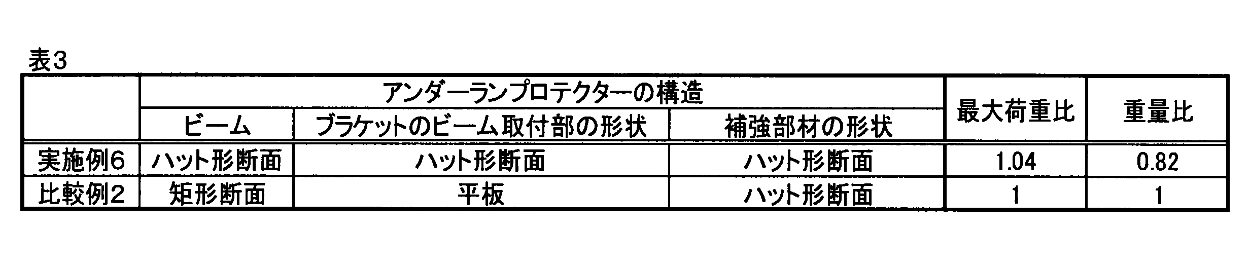
次に、本発明の第3の実施形態に係るアンダーランプロテクターと、従来構造のアンダーランプロテクターとを用いて、耐荷重性評価試験を実施した。本発明の第3の実施形態に係るアンダーランプロテクターとは、図24に示す構成のアンダーランプロテクター(実施例7)であり、ビーム取付面の車幅方向Wの外側の先端部分に屈曲部が設けられている。一方、従来構造のアンダーランプロテクターとは、図24に示すアンダーランプロテクターから、ビーム取付面の車幅方向Wの外側の先端部分における屈曲部を有しないアンダーランプロテクター(比較例3)である。ビームは、引張強度が780MPa級のハイテン鋼で形成され、ステーおよびブラケットは、引張強度が540MPa級の厚手材で形成されている。また、平面視において構造体本体部とビーム取付面との間を架け渡すように設けられる第3の補強部材は、引張強度が540MPa級の厚手材で形成されている。また、実施例9に係る屈曲部の曲率半径は100mmであり、L1/L2は0.6である。
次に、異なる構造のアンダーランプロテクターの、当該構造の違いによる耐荷重性能への影響について評価した。本実施例におけるアンダーランプロテクターの構造の種類は、ビーム取付面の車幅方向Wの外側の先端に屈曲部を設けた構造A、構造Aに対して図27に示した補強板が追加された構造B、構造Aに対して図31に示した間仕切り部材が追加された構造Cの3種類である。なお、第3の補強部材の形状は、各構造で同一である。また、構造Aについては、図25に示した第3の補強部材の車両前後方向Lの長さL1を2通り用意した。また、構造A~Cについては、屈曲部の曲率半径を3通り用意した。これら実施例8~実施例19について、耐荷重性評価試験が行われた。試験条件は上記の実験例3と同一であるため、説明を省略する。
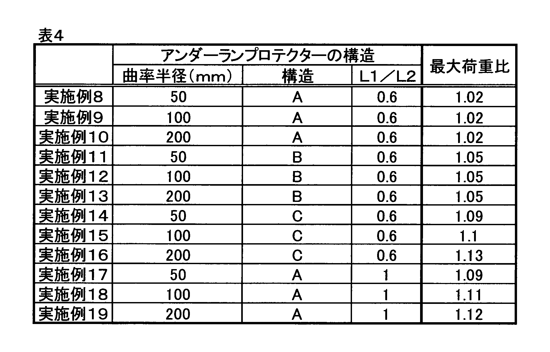
次に、本発明の第4の実施形態に係るアンダーランプロテクターと、従来構造のアンダーランプロテクターとを用いて、耐荷重性評価試験を実施した。従来構造のアンダーランプロテクターとは、上記の比較例1に係るアンダーランプロテクターである。また、本発明の第4の実施形態に係るアンダーランプロテクターとは、図32に示す構成のアンダーランプロテクター(実施例20)である。ビームは、引張強度が780MPa級のハイテン鋼で形成され、ステーおよびブラケットは、引張強度が540MPa級の厚手材で形成されている。また、第1の補強部材は、引張強度が780MPa級の厚手材で形成されている。また、第3の補強部材は、引張強度が540MPa級の厚手材で形成されている。

2 ビーム
2a 第1の上面部
2b 第1の下面部
2c 第1の側面部
2d 第1のフランジ部
3 接続構造体
3a 接続構造体の先端部
3b 接続構造体の閉断面部
4 ステー
4a 開口面
4b 補強部材取付面(背面)
4c ステーの側壁部
5 フレーム取付板
6 突出部
6a 突出上面部
6b 突出下面部
6c 突出側面部
7 突出部のボルト穴
8 ビームのボルト穴
9 第1の補強部材
9a 第1の補強部材上面部
9b 第1の補強部材下面部
9c 第1の補強部材側面部
9d 第1の補強部材凸部
10 ブラケット
10a ステー取付部(ステー取付面)
10b ビーム取付部(ビーム取付面)
10c 第2の上面部
10d 第2の下面部
10e 第2の側面部
10f 第2のフランジ部
11 ブラケットのボルト穴
12 第1の補強部材のボルト穴
15 第3の補強部材
15a、15b 第3の補強部材の先端部
16 屈曲部
17 補強板
18 間仕切り部材
20 車体フレーム
21 フレーム取付板のボルト穴
22、23 ボルト
90 第2の補強部材
90a 第2の補強部材上面部
90b 第2の補強部材下面部
90c 第2の補強部材側面部
90e 第2の補強部材フランジ部
101、102 圧子
Claims (17)
- 車幅方向に延びるビームと、
前記ビームを車体フレームに接続する接続構造体と、
を備え、
前記ビームは、車幅方向に垂直な断面視において、
対向する第1の上面部および第1の下面部と、
前記第1の上面部および前記第1の下面部の一端を接続する第1の側面部と、
前記第1の上面部および前記第1の下面部の他端において、鉛直方向外方に突出するように形成される第1のフランジ部のそれぞれと、を有し、
前記接続構造体に設けられ、前記ビームの内方に突出して前記ビームの内方に配置される突出部と前記第1の上面部および前記第1の下面部との、または、前記接続構造体に設けられるビーム取付部材と前記第1のフランジ部との、少なくともいずれかにおける接合により、前記ビームが前記接続構造体に固定されている、車両の端部構造。 - 前記接続構造体に前記突出部が設けられている場合、前記突出部には、前記第1の側面部に対向する突出側面部が形成されている、請求項1に記載の車両の端部構造。
- 前記接続構造体にビーム取付部材が設けられ、前記ビーム取付部材が前記第1のフランジ部と固定されている場合、
前記ビーム取付部材は、車幅方向に垂直な断面視において、
対向する第2の上面部および第2の下面部と、
前記第2の上面部および前記第2の下面部の一端を接続する第2の側面部と、
前記第2の上面部および前記第2の下面部の他端において、鉛直方向外方に突出するように形成された第2のフランジ部とを有し、
前記第1のフランジ部と前記第2のフランジ部とが固定されている、請求項1に記載の車両の端部構造。 - 前記第2の側面部は、前記第1のフランジ部に対して車両前後方向の車内側に位置している、請求項3に記載の車両の端部構造。
- 前記接続構造体に前記ビーム取付部材が設けられ、前記ビーム取付部材が前記第1のフランジ部と固定されている場合、
車幅方向において前記ビームの開口部の少なくとも前記接続構造体と対向する領域に第1の補強部材が設けられ、
車幅方向に垂直な断面視において前記ビームと前記第1の補強部材により閉断面が形成されている、請求項1~4のいずれか1項に記載の車両の端部構造。 - 前記第1の補強部材は、車幅方向に垂直な断面視において、
対向する第1の補強部材上面部および第1の補強部材下面部と、
前記第1の補強部材上面部および前記第1の補強部材下面部の一端を接続する第1の補強部材側面部とを有し、
前記第1の補強部材が前記ビームの内方に配置され、前記第1の上面部と前記第1の補強部材上面部とが固定され、前記第1の下面部と前記第1の補強部材下面部とが固定されている、請求項5に記載の車両の端部構造。 - 前記第1の補強部材側面部に、前記第1のフランジ部に対して車両前後方向の車内側に突出する凸部が形成されている、請求項6に記載の車両の端部構造。
- 前記第1の補強部材側面部の少なくとも一部が、前記接続構造体に当接する、請求項7に記載の車両の端部構造。
- 前記ビームの開口部の少なくとも前記ビーム取付部材と対向している領域に第2の補強部材が設けられ、
前記第2の補強部材は、車幅方向に垂直な断面視において、
対向する第2の補強部材上面部および第2の補強部材下面部と、
前記第2の補強部材上面部および前記第2の補強部材下面部の一端を接続する第2の補強部材側面部と、
前記第2の補強部材上面部および前記第2の補強部材下面部の他端において、鉛直方向外方に突出するように形成された第2の補強部材フランジ部とを有し、
前記第2の補強部材が前記ビームの内方に配置され、
前記第2の補強部材フランジ部が前記第1の側面部に固定され、
前記第2の補強部材側面部が、前記ビーム取付部材に当接する、請求項3または4に記載の車両の端部構造。 - 前記接続構造体に前記ビーム取付部材が設けられ、前記ビーム取付部材が前記第1のフランジ部と固定されている場合、
前記接続構造体は、鉛直方向に延びるように設けられた構造体本体部をさらに含み、
前記ビーム取付部材は、
前記ビームが取り付けられ、車幅方向外側の端部に車両前後方向の車内側に向けて屈曲した屈曲部を有するビーム取付面と、
平面視において前記ビーム取付面に直角な面を有し、前記構造体本体部に取り付けられる本体接続面と、
を有し、
平面視において、前記構造体本体部と前記ビーム取付面との間を架け渡すように少なくとも1つの第3の補強部材がさらに設けられる、請求項1~9のいずれか1項に記載の車両の端部構造。 - 前記屈曲部の曲率半径が50~200mmである、請求項10に記載の車両の端部構造。
- 前記第3の補強部材の車両前後方向長さL1と、前記構造体本体部の前記第3の補強部材が取り付けられた面の車両前後方向長さL2との比率L1/L2が0.8以上となるように、前記第3の補強部材が設けられている、請求項10または11に記載の車両の端部構造。
- 前記構造体本体部は、平面視において車幅方向に開口部が設けられたU字状の断面形状を有し、
前記構造体本体部と前記本体接続面により水平断面形状が閉断面となる閉断面部がさらに設けられる、請求項10~12のいずれか1項に記載の車両の端部構造。 - 前記第3の補強部材が鉛直方向に複数設けられる場合において、
前記閉断面部の内方に、前記第3の補強部材の先端部のうち、車両前後方向の後方側先端部の位置に合わせて配置された補強板が設けられ、
前記補強板は、複数の前記第3の補強部材のうち最も下側に位置する前記第3の補強部材の前記後方側先端部から最も上側に位置する前記第3の補強部材の前記後方側先端部まで延びるような形状を有する、請求項13に記載の車両の端部構造。 - 前記閉断面部の水平断面視において、前記閉断面部の内方の空間を埋めるように間仕切り部材が設けられ、
前記間仕切り部材は、前記第3の補強部材の少なくともいずれかの設置高さに合わせて配置されている、請求項13または14に記載の車両の端部構造。 - 前記車両の端部構造は、アンダーランプロテクターである、請求項1~15のいずれか1項に記載の車両の端部構造。
- 車幅方向に延びるビームと、前記ビームと車体フレームを接続する接続構造体とを備え、
前記接続構造体は、
鉛直方向に延びるように設けられた構造体本体部と、
前記ビームが取り付けられるビーム取付部材と、
を備え、
前記ビーム取付部材は、
前記ビームが取り付けられ、車幅方向外側の端部に車両前後方向の車内側に向けて屈曲した屈曲部を有するビーム取付面と、
平面視において前記ビーム取付面に直角な面を有し、前記構造体本体部に取り付けられる本体接続面と、
を有し、
平面視において、前記構造体本体部と前記ビーム取付面との間を架け渡すように少なくとも1つの補強部材がさらに設けられる、車両の端部構造。
Priority Applications (7)
| Application Number | Priority Date | Filing Date | Title |
|---|---|---|---|
| KR1020197023323A KR20190095560A (ko) | 2015-02-06 | 2016-02-01 | 차량의 단부 구조 |
| MX2017009928A MX387976B (es) | 2015-02-06 | 2016-02-01 | Estructura de extremo de vehículo. |
| JP2016573352A JP6492333B2 (ja) | 2015-02-06 | 2016-02-01 | 車両の端部構造 |
| US15/546,420 US10427633B2 (en) | 2015-02-06 | 2016-02-01 | End structure of vehicle |
| KR1020177023866A KR102183528B1 (ko) | 2015-02-06 | 2016-02-01 | 차량의 단부 구조 |
| KR1020197023324A KR20190095561A (ko) | 2015-02-06 | 2016-02-01 | 차량의 단부 구조 |
| CN201680008957.8A CN107206953B (zh) | 2015-02-06 | 2016-02-01 | 车辆的端部构造 |
Applications Claiming Priority (8)
| Application Number | Priority Date | Filing Date | Title |
|---|---|---|---|
| JP2015-022216 | 2015-02-06 | ||
| JP2015-022204 | 2015-02-06 | ||
| JP2015022216 | 2015-02-06 | ||
| JP2015022204 | 2015-02-06 | ||
| JP2015137758 | 2015-07-09 | ||
| JP2015-137758 | 2015-07-09 | ||
| JP2015-212519 | 2015-10-29 | ||
| JP2015212519 | 2015-10-29 |
Publications (1)
| Publication Number | Publication Date |
|---|---|
| WO2016125745A1 true WO2016125745A1 (ja) | 2016-08-11 |
Family
ID=56564089
Family Applications (1)
| Application Number | Title | Priority Date | Filing Date |
|---|---|---|---|
| PCT/JP2016/052924 Ceased WO2016125745A1 (ja) | 2015-02-06 | 2016-02-01 | 車両の端部構造 |
Country Status (6)
| Country | Link |
|---|---|
| US (1) | US10427633B2 (ja) |
| JP (1) | JP6492333B2 (ja) |
| KR (3) | KR20190095560A (ja) |
| CN (1) | CN107206953B (ja) |
| MX (2) | MX387976B (ja) |
| WO (1) | WO2016125745A1 (ja) |
Cited By (4)
| Publication number | Priority date | Publication date | Assignee | Title |
|---|---|---|---|---|
| JP2018114847A (ja) * | 2017-01-18 | 2018-07-26 | いすゞ自動車株式会社 | リアアンダーランプロテクタ |
| JP2018197011A (ja) * | 2017-05-23 | 2018-12-13 | いすゞ自動車株式会社 | フロントアンダーランプロテクタ取付構造 |
| KR20190030745A (ko) | 2016-08-26 | 2019-03-22 | 신닛테츠스미킨 카부시키카이샤 | 언더런 프로텍터의 지지 구조 |
| CN115140202A (zh) * | 2022-07-21 | 2022-10-04 | 江西江铃专用车辆厂有限公司 | 一种轻量化冷藏车结构及其制造方法 |
Families Citing this family (6)
| Publication number | Priority date | Publication date | Assignee | Title |
|---|---|---|---|---|
| DE102019105188A1 (de) * | 2019-02-28 | 2020-09-03 | Böllhoff Verbindungstechnik GmbH | Aufprallschutzverstärkung einer Fahrzeugkonstruktion sowie Verbindungs- und Herstellungsverfahren dafür |
| RU199808U1 (ru) * | 2020-03-17 | 2020-09-21 | Общество с ограниченной ответственностью "Объединенный инженерный центр" (ООО "ОИЦ") | Система установки фронтального радара на среднетоннажных грузовиках |
| CN111634250A (zh) * | 2020-06-05 | 2020-09-08 | 成都先进金属材料产业技术研究院有限公司 | 一种车辆防护栏 |
| US20230102985A1 (en) * | 2021-09-27 | 2023-03-30 | Kabushiki Kaisha Kobe Seiko Sho (Kobe Steel, Ltd.) | Seat back frame for automobile |
| CN113865437B (zh) * | 2021-10-20 | 2023-02-24 | 重庆大江智防特种装备有限公司 | 一种车辆阻截装置 |
| CN116691568A (zh) * | 2022-02-24 | 2023-09-05 | 北京车和家汽车科技有限公司 | 防撞梁以及车辆 |
Citations (4)
| Publication number | Priority date | Publication date | Assignee | Title |
|---|---|---|---|---|
| JP2001122058A (ja) * | 1999-10-22 | 2001-05-08 | Suzuki Motor Corp | リアバンパーメンバステイの構造 |
| JP2004243984A (ja) * | 2003-02-17 | 2004-09-02 | Press Kogyo Co Ltd | フロント・アンダーラン・プロテクタ |
| JP2010241247A (ja) * | 2009-04-03 | 2010-10-28 | Press Kogyo Co Ltd | トラック用アンダーラン・プロテクタ構造 |
| JP2014125000A (ja) * | 2012-12-25 | 2014-07-07 | Toyota Motor Corp | リヤバンパリインフォースメント構造及び車両後部構造 |
Family Cites Families (10)
| Publication number | Priority date | Publication date | Assignee | Title |
|---|---|---|---|---|
| JP4222911B2 (ja) | 2003-09-17 | 2009-02-12 | プレス工業株式会社 | フロント・アンダーラン・プロテクタ |
| JP4383916B2 (ja) | 2004-02-12 | 2009-12-16 | プレス工業株式会社 | リア・アンダーラン・プロテクタ |
| JP4450637B2 (ja) | 2004-02-12 | 2010-04-14 | プレス工業株式会社 | リア・アンダーラン・プロテクタ |
| KR100867841B1 (ko) * | 2006-11-21 | 2008-11-10 | 현대자동차주식회사 | 자동차의 전방차체 구조 |
| CN201224371Y (zh) | 2008-05-15 | 2009-04-22 | 武汉理工大学 | 吸能式车辆保险杠 |
| JP5741041B2 (ja) * | 2011-02-14 | 2015-07-01 | マツダ株式会社 | ダイカストアルミ合金製クラッシュカン |
| JP5422595B2 (ja) * | 2011-04-14 | 2014-02-19 | 豊田鉄工株式会社 | バンパーステイ取付構造および荷重伝達部材 |
| JP5618973B2 (ja) * | 2011-12-13 | 2014-11-05 | 豊田鉄工株式会社 | 車両用バンパービーム |
| JP5907126B2 (ja) * | 2013-08-02 | 2016-04-20 | トヨタ自動車株式会社 | 自動車の車体前部構造 |
| CN203558028U (zh) | 2013-09-26 | 2014-04-23 | 长城汽车股份有限公司 | 用于车辆的前防撞梁及具有其的车辆 |
-
2016
- 2016-02-01 KR KR1020197023323A patent/KR20190095560A/ko not_active Withdrawn
- 2016-02-01 KR KR1020177023866A patent/KR102183528B1/ko active Active
- 2016-02-01 KR KR1020197023324A patent/KR20190095561A/ko not_active Withdrawn
- 2016-02-01 US US15/546,420 patent/US10427633B2/en active Active
- 2016-02-01 MX MX2017009928A patent/MX387976B/es unknown
- 2016-02-01 CN CN201680008957.8A patent/CN107206953B/zh active Active
- 2016-02-01 WO PCT/JP2016/052924 patent/WO2016125745A1/ja not_active Ceased
- 2016-02-01 JP JP2016573352A patent/JP6492333B2/ja active Active
-
2017
- 2017-08-01 MX MX2021007386A patent/MX2021007386A/es unknown
Patent Citations (4)
| Publication number | Priority date | Publication date | Assignee | Title |
|---|---|---|---|---|
| JP2001122058A (ja) * | 1999-10-22 | 2001-05-08 | Suzuki Motor Corp | リアバンパーメンバステイの構造 |
| JP2004243984A (ja) * | 2003-02-17 | 2004-09-02 | Press Kogyo Co Ltd | フロント・アンダーラン・プロテクタ |
| JP2010241247A (ja) * | 2009-04-03 | 2010-10-28 | Press Kogyo Co Ltd | トラック用アンダーラン・プロテクタ構造 |
| JP2014125000A (ja) * | 2012-12-25 | 2014-07-07 | Toyota Motor Corp | リヤバンパリインフォースメント構造及び車両後部構造 |
Cited By (6)
| Publication number | Priority date | Publication date | Assignee | Title |
|---|---|---|---|---|
| KR20190030745A (ko) | 2016-08-26 | 2019-03-22 | 신닛테츠스미킨 카부시키카이샤 | 언더런 프로텍터의 지지 구조 |
| US10787142B2 (en) | 2016-08-26 | 2020-09-29 | Nippon Steel Corporation | Supporting structure for underrun protector |
| JP2018114847A (ja) * | 2017-01-18 | 2018-07-26 | いすゞ自動車株式会社 | リアアンダーランプロテクタ |
| JP2018197011A (ja) * | 2017-05-23 | 2018-12-13 | いすゞ自動車株式会社 | フロントアンダーランプロテクタ取付構造 |
| CN115140202A (zh) * | 2022-07-21 | 2022-10-04 | 江西江铃专用车辆厂有限公司 | 一种轻量化冷藏车结构及其制造方法 |
| CN115140202B (zh) * | 2022-07-21 | 2023-08-01 | 江西江铃专用车辆厂有限公司 | 一种轻量化冷藏车结构及其制造方法 |
Also Published As
| Publication number | Publication date |
|---|---|
| JP6492333B2 (ja) | 2019-04-03 |
| KR20170108998A (ko) | 2017-09-27 |
| US20180265025A1 (en) | 2018-09-20 |
| KR20190095561A (ko) | 2019-08-14 |
| MX2017009928A (es) | 2017-12-07 |
| MX387976B (es) | 2025-03-19 |
| CN107206953B (zh) | 2019-12-17 |
| MX2021007386A (es) | 2021-07-15 |
| JPWO2016125745A1 (ja) | 2017-10-26 |
| US10427633B2 (en) | 2019-10-01 |
| KR102183528B1 (ko) | 2020-11-26 |
| CN107206953A (zh) | 2017-09-26 |
| KR20190095560A (ko) | 2019-08-14 |
Similar Documents
| Publication | Publication Date | Title |
|---|---|---|
| JP6492333B2 (ja) | 車両の端部構造 | |
| JP4407755B2 (ja) | 車両用フード構造 | |
| US9868472B2 (en) | Bonnet structure of automotive vehicle | |
| JP6227681B2 (ja) | 車体構造 | |
| JP4875558B2 (ja) | 車体フレーム構造 | |
| JP4875559B2 (ja) | 車体フレーム構造 | |
| CN108973907A (zh) | 保险杠横梁结构 | |
| US20100171340A1 (en) | Vehicle body frame structure | |
| JP6142978B1 (ja) | 車両前部構造 | |
| CN101528529B (zh) | 车辆底架 | |
| JP2017159894A (ja) | 車両用構造部材 | |
| JP2017159896A (ja) | 車両用構造部材 | |
| JP2017159895A (ja) | 車両用構造部材 | |
| JP4900262B2 (ja) | 車体前部構造 | |
| JP4314992B2 (ja) | 車体構造 | |
| JP5714967B2 (ja) | 車体の衝撃緩衝構造 | |
| JP4449758B2 (ja) | 車体構造 | |
| JP4923004B2 (ja) | 自動車の車体前部構造 | |
| JP6221164B2 (ja) | 車体構造 | |
| KR20250151462A (ko) | 자동차의 서브프레임 구조 | |
| JP2005067347A (ja) | 車体前部構造 | |
| JP2010208538A (ja) | 車両下部構造、及び車両 | |
| CN109070941B (zh) | 机动车辆的前挡泥板结构 | |
| JP6566018B2 (ja) | 車両の衝撃吸収構造 | |
| JP4687033B2 (ja) | 車体の前部構造 |
Legal Events
| Date | Code | Title | Description |
|---|---|---|---|
| 121 | Ep: the epo has been informed by wipo that ep was designated in this application |
Ref document number: 16746576 Country of ref document: EP Kind code of ref document: A1 |
|
| ENP | Entry into the national phase |
Ref document number: 2016573352 Country of ref document: JP Kind code of ref document: A |
|
| WWE | Wipo information: entry into national phase |
Ref document number: 15546420 Country of ref document: US |
|
| WWE | Wipo information: entry into national phase |
Ref document number: MX/A/2017/009928 Country of ref document: MX |
|
| NENP | Non-entry into the national phase |
Ref country code: DE |
|
| ENP | Entry into the national phase |
Ref document number: 20177023866 Country of ref document: KR Kind code of ref document: A |
|
| 122 | Ep: pct application non-entry in european phase |
Ref document number: 16746576 Country of ref document: EP Kind code of ref document: A1 |