WO2016125712A1 - 電流検出回路、電流検出装置及び切替え装置 - Google Patents
電流検出回路、電流検出装置及び切替え装置 Download PDFInfo
- Publication number
- WO2016125712A1 WO2016125712A1 PCT/JP2016/052763 JP2016052763W WO2016125712A1 WO 2016125712 A1 WO2016125712 A1 WO 2016125712A1 JP 2016052763 W JP2016052763 W JP 2016052763W WO 2016125712 A1 WO2016125712 A1 WO 2016125712A1
- Authority
- WO
- WIPO (PCT)
- Prior art keywords
- current
- current path
- value
- detection circuit
- voltage value
- Prior art date
Links
Images
Classifications
-
- G—PHYSICS
- G05—CONTROLLING; REGULATING
- G05F—SYSTEMS FOR REGULATING ELECTRIC OR MAGNETIC VARIABLES
- G05F1/00—Automatic systems in which deviations of an electric quantity from one or more predetermined values are detected at the output of the system and fed back to a device within the system to restore the detected quantity to its predetermined value or values, i.e. retroactive systems
-
- H—ELECTRICITY
- H02—GENERATION; CONVERSION OR DISTRIBUTION OF ELECTRIC POWER
- H02M—APPARATUS FOR CONVERSION BETWEEN AC AND AC, BETWEEN AC AND DC, OR BETWEEN DC AND DC, AND FOR USE WITH MAINS OR SIMILAR POWER SUPPLY SYSTEMS; CONVERSION OF DC OR AC INPUT POWER INTO SURGE OUTPUT POWER; CONTROL OR REGULATION THEREOF
- H02M3/00—Conversion of dc power input into dc power output
- H02M3/02—Conversion of dc power input into dc power output without intermediate conversion into ac
- H02M3/04—Conversion of dc power input into dc power output without intermediate conversion into ac by static converters
- H02M3/10—Conversion of dc power input into dc power output without intermediate conversion into ac by static converters using discharge tubes with control electrode or semiconductor devices with control electrode
- H02M3/145—Conversion of dc power input into dc power output without intermediate conversion into ac by static converters using discharge tubes with control electrode or semiconductor devices with control electrode using devices of a triode or transistor type requiring continuous application of a control signal
- H02M3/155—Conversion of dc power input into dc power output without intermediate conversion into ac by static converters using discharge tubes with control electrode or semiconductor devices with control electrode using devices of a triode or transistor type requiring continuous application of a control signal using semiconductor devices only
- H02M3/156—Conversion of dc power input into dc power output without intermediate conversion into ac by static converters using discharge tubes with control electrode or semiconductor devices with control electrode using devices of a triode or transistor type requiring continuous application of a control signal using semiconductor devices only with automatic control of output voltage or current, e.g. switching regulators
- H02M3/157—Conversion of dc power input into dc power output without intermediate conversion into ac by static converters using discharge tubes with control electrode or semiconductor devices with control electrode using devices of a triode or transistor type requiring continuous application of a control signal using semiconductor devices only with automatic control of output voltage or current, e.g. switching regulators with digital control
-
- F—MECHANICAL ENGINEERING; LIGHTING; HEATING; WEAPONS; BLASTING
- F02—COMBUSTION ENGINES; HOT-GAS OR COMBUSTION-PRODUCT ENGINE PLANTS
- F02D—CONTROLLING COMBUSTION ENGINES
- F02D41/00—Electrical control of supply of combustible mixture or its constituents
- F02D41/20—Output circuits, e.g. for controlling currents in command coils
-
- H—ELECTRICITY
- H02—GENERATION; CONVERSION OR DISTRIBUTION OF ELECTRIC POWER
- H02M—APPARATUS FOR CONVERSION BETWEEN AC AND AC, BETWEEN AC AND DC, OR BETWEEN DC AND DC, AND FOR USE WITH MAINS OR SIMILAR POWER SUPPLY SYSTEMS; CONVERSION OF DC OR AC INPUT POWER INTO SURGE OUTPUT POWER; CONTROL OR REGULATION THEREOF
- H02M7/00—Conversion of ac power input into dc power output; Conversion of dc power input into ac power output
- H02M7/42—Conversion of dc power input into ac power output without possibility of reversal
- H02M7/44—Conversion of dc power input into ac power output without possibility of reversal by static converters
- H02M7/48—Conversion of dc power input into ac power output without possibility of reversal by static converters using discharge tubes with control electrode or semiconductor devices with control electrode
-
- H—ELECTRICITY
- H03—ELECTRONIC CIRCUITRY
- H03M—CODING; DECODING; CODE CONVERSION IN GENERAL
- H03M1/00—Analogue/digital conversion; Digital/analogue conversion
- H03M1/06—Continuously compensating for, or preventing, undesired influence of physical parameters
- H03M1/0602—Continuously compensating for, or preventing, undesired influence of physical parameters of deviations from the desired transfer characteristic
- H03M1/0609—Continuously compensating for, or preventing, undesired influence of physical parameters of deviations from the desired transfer characteristic at two points of the transfer characteristic, i.e. by adjusting two reference values, e.g. offset and gain error
-
- H—ELECTRICITY
- H02—GENERATION; CONVERSION OR DISTRIBUTION OF ELECTRIC POWER
- H02M—APPARATUS FOR CONVERSION BETWEEN AC AND AC, BETWEEN AC AND DC, OR BETWEEN DC AND DC, AND FOR USE WITH MAINS OR SIMILAR POWER SUPPLY SYSTEMS; CONVERSION OF DC OR AC INPUT POWER INTO SURGE OUTPUT POWER; CONTROL OR REGULATION THEREOF
- H02M1/00—Details of apparatus for conversion
- H02M1/0003—Details of control, feedback or regulation circuits
- H02M1/0009—Devices or circuits for detecting current in a converter
Definitions
- the present invention relates to a current detection circuit that outputs a voltage value corresponding to a current value flowing through a current path, a current detection device including the current detection circuit, and a current path through which a current flows to a voltage value output by the current detection circuit.
- the present invention relates to a switching device that switches in response.
- Patent Document 1 As a power supply device mounted on a vehicle, a power supply device (see, for example, Patent Document 1) in which power is supplied to a load via two current paths has been proposed.
- a DCDC converter is provided in one of the two current paths.
- the DCDC converter transforms an applied voltage and applies the transformed voltage to a load. As a result, the load is fed.
- the other current path is not provided with a DCDC converter, and is directly supplied to the load.
- the current path used for power supply to the load is switched to one of the two current paths described above.
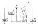
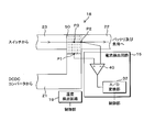
- FIG. 1 is a block diagram showing a main part configuration of a conventional power supply device 8.
- the conventional power supply device 8 one end of the generator 80 is connected to one end of each of the switch 81 and the DCDC converter 82, and the other end of each of the switch 81 and the DCDC converter 82 is connected to one end of the resistor R8. .
- the other end of the resistor R8 is connected to one end of the load 83.
- the other ends of the generator 80 and the load 83 are grounded.
- One end and the other end of the resistor R8 are connected to the plus terminal and the minus terminal of the differential amplifier 84, respectively, and the output terminal of the differential amplifier 84 is connected to an A / D (Analog / Digital) converter 85.
- the A / D conversion unit 85 is further connected to the control unit 86.
- the control unit 86 controls on / off of the switch 81 and operation / stop of the DCDC converter 82.
- the control unit 86 turns off the switch 81 to operate the DCDC converter 82
- the DCDC converter 82 steps down the direct current output voltage output from the generator 80, and passes the stepped down voltage through the resistor R8. Supply to load 83.
- the control unit 86 turns on the switch 81 to stop the operation of the DCDC converter 82, the generator 80 supplies the output voltage to the load 83 via the switch 81 and the resistor R8.
- the differential amplifier 84 amplifies the voltage value across the resistor R8 and outputs the amplified analog voltage value to the A / D converter 85.
- the A / D conversion unit 85 converts the analog voltage value into a digital voltage value, and outputs the converted digital voltage value to the control unit 86. Since the voltage value across the resistor R8 is proportional to the value of the current flowing through the resistor R8, the resistor R8, the differential amplifier 84, and the A / D converter 85 function as a current detection circuit.
- the control unit 86 normally turns off the switch 81 and operates the DCDC converter 82.
- the value of the current that can be passed through the DCDC converter 82 is limited to a predetermined value. Therefore, a first current value that is less than a predetermined value and a second current value that is less than or equal to the first current value are set.
- the switch 81 is off and the DCDC converter 82 is operating, the current flowing through the resistor R8 is equal to or higher than the first current value, and the voltage value output from the A / D converter 85 is equal to or higher than the first voltage value.
- the control unit 86 stops the operation of the DCDC converter 82 and turns on the switch 81.
- the current path of the current flowing from the generator 80 to the load 83 is switched from the first path through which the current flows through the DCDC converter 82 to the second path through which the current flows through the switch 81.
- the control unit 86 since the control unit 86 switches the current path, even when the load 83 needs to supply a current of a predetermined value or more, it is possible to continue supplying the current to the load 83.
- the switch 81 When the switch 81 is on and the operation of the DCDC converter 82 is stopped, the value of the current flowing through the second path is less than the second current value and the second voltage value output from the A / D converter 85.
- the control unit 86 turns off the switch 81 and operates the DCDC converter 82. Thereby, the current path of the current flowing from the generator 80 to the load 83 is switched from the second path to the first path. The voltage that is stepped down by the DCDC converter 82 is supplied to the load 83 again.
- the above-described current detection circuit and control unit 86 function as a switching device that switches the current path through which the current flows to the first path or the second path.
- the A / D conversion unit 85 performs processing such as rounding off or rounding down, and among the voltage values obtained by equally dividing the reference voltage value by a predetermined number, the voltage value output by the differential amplifier 84 is first or second.
- the voltage value output from the differential amplifier 84 is quantized to a close voltage value.
- a current less than the first current value flows through the first path, and a current greater than the second current value flows through the second path. Since the second path is provided for flowing a current equal to or higher than the first current value, a current equal to or higher than the first current value flows through the second path.
- the reference voltage value of the A / D converter 85 is set to 10 V or more.
- the reference voltage value is 10V and the A / D conversion unit 85 converts the voltage value into a 10-bit digital value
- the A / D conversion unit 85 sets 10V (reference voltage value) to 1023 (predetermined number).
- the voltage value output by the differential amplifier 84 is quantized to the voltage value first or second closest to the voltage value output by the differential amplifier 84. At this time, the interval between the scales is about 9.78 mV.
- the value of the current flowing through the first path varies in the range of zero to 100A.
- the reference voltage value of the A / D converter 85 can be set to 5 V.
- the A / D converter 85 is first or second closest to the voltage value output by the differential amplifier 84 among the voltage values obtained by equally dividing 5V (reference voltage value) by 1023 (predetermined number).
- the voltage value output from the differential amplifier 84 is quantized into the voltage value.
- the interval between the scales is about 4.89 mV.
- the reference voltage value is 5V, since the interval of the scale is small, the current detection circuit configured by the resistor R8, the differential amplifier 84, and the A / D conversion unit 85 can accurately determine the value of the current flowing through the first path. Can be detected.
- the reference voltage value of the A / D conversion unit 85 is set according to the maximum value of the current flowing through the second path. There is a problem that the value of the current flowing through the current cannot be detected with high accuracy. In this case, there is a possibility that the current path cannot be switched appropriately.
- the present invention has been made in view of such circumstances, and an object of the present invention is to provide an inexpensive current detection circuit capable of outputting a voltage value accurately indicating a current value flowing through each of two current paths.
- the present invention also provides a current detection device and a switching device including the current detection circuit.
- the current detection circuit corresponds to a current value flowing through the first current path from the first conductive plate to the second conductive plate and the second current path from the third conductive plate to the second conductive plate.
- the current detection circuit for outputting a voltage value further includes a potential difference detection unit that detects a value related to a potential difference between two points located on the plate surfaces of the first conductive plate and the second conductive plate.
- a current flows through the first current path from the first conductive plate to the second conductive plate or the second current path from the third conductive plate to the second conductive plate.
- a value relating to a potential difference between a point located on the plate surface of the first conductive plate and a point located on the plate surface of the third conductive plate is detected.
- the value relating to the potential difference between the two points varies according to the current value flowing through the first current path and the current value flowing through the second current path.
- a value related to a potential difference between two points detected when a certain value of current flows in the second current path is detected when a current of the same value flows in the first current path. Different from the value related to the potential difference between points.
- the value relating to the potential difference between the two points is a voltage value between the two points or a current value flowing between the two points.
- the voltage value output from the circuit is a voltage value based on a voltage value between two points or a current value flowing between the two points.
- a value related to a potential difference between two points when a current of 100 A flows in the first current path and a value related to a potential difference between two points when a current of 200 A flows in the second current path. can be matched.
- a voltage value that accurately indicates the current value flowing through each of the first current path and the second current path is output.
- pieces may be one, manufacturing cost is cheap.
- the current detection circuit includes a conducting wire connected between the two points, and the potential difference detection unit detects a current value flowing through the conducting wire.
- the value of the current flowing in the conducting wire connected between the point located on the plate surface of the first conductive plate and the point located on the plate surface of the second conductive plate is detected.
- the current detection circuit according to the present invention is characterized in that the potential difference detection unit detects a voltage value between the two points.
- a voltage value between a point located on the plate surface of the first conductive plate and a point located on the plate surface of the second conductive plate is detected.
- each of the first conductive plate and the third conductive plate is connected to the first conductive plate, the second conductive plate, and the third conductive plate through a resistance unit having a lower conductivity. It is characterized by being connected to the second conductive plate.
- each of the first conductive plate and the third conductive plate is connected to the second conductive plate via a resistance portion having a lower conductivity than the first conductive plate, the second conductive plate, and the third conductive plate. ing. For this reason, the voltage value between the point located in the board surface of a 1st electroconductive board and the point located in the board surface of a 2nd electroconductive board is large.
- the current detection device is a temperature detection that detects a temperature value of a conductor constituted by connecting the above-described current detection circuit and the first conductive plate and the third conductive plate to the second conductive plate. And a calculation unit that calculates a current value flowing through the first current path or the second current path based on the temperature value detected by the temperature detection unit and the voltage value output by the current detection circuit. It is characterized by that.
- the first conductive plate and the third conductive plate are connected to the second conductive plate, and the temperature value of the conductor constituted by the first conductive plate, the second conductive plate, and the third conductive plate is determined. To detect. Based on the detected temperature value and the voltage value output by the current detection circuit, the current value flowing in the first current path or the second current path is calculated.
- the current detection device includes the above-described current detection circuit, a temperature detection unit that detects a temperature value of the resistance unit, a temperature value detected by the temperature detection unit, and a voltage output by the current detection circuit. And a calculation unit that calculates a value of a current flowing through the first current path or the second current path based on the value.
- the temperature value of the resistance portion is detected, and the current value flowing through the first current path or the second current path is calculated based on the detected temperature value and the voltage value output by the current detection circuit. .
- a switching device includes the above-described current detection circuit and a switching unit that switches a current path through which a current flows to the first current path or the second current path, and the switching unit includes the first current path and the current path. Switching is performed based on which of the second current paths the current is flowing and the voltage value output by the current detection circuit.
- the current path through which the current flows should be switched to the second current path based on the voltage value output by the current detection circuit in the state where the current flows through the first current path.
- a determination is made as to whether or not the current path through which the current flows should be switched to the first current path based on the voltage value output by the current detection circuit in a state where the current is flowing through the second current path.
- the current path through which the current flows is appropriately switched by adjusting the positions of the two points so that the voltage value accurately indicating the current value flowing through each of the first current path and the second current path is output. It is possible.
- the switching device includes the above-described current detection circuit, a switching unit that switches a current path through which a current flows to the first current path or the second current path, and the first conductive plate and the third conductive plate, respectively.
- a temperature detection unit that detects a temperature value of a conductor formed by being connected to the second conductive plate, and the switching unit determines whether the current flows in the first current path or the second current path. The switching is performed based on the voltage value output by the current detection circuit and the temperature value detected by the temperature detection unit.
- the first conductive plate and the third conductive plate are connected to the second conductive plate, and the temperature value of the conductor constituted by the first conductive plate, the second conductive plate, and the third conductive plate is determined.
- the current path through which the current flows should be switched based not only on whether the current flows through the first current path or the second current path and the voltage value output from the voltage detection circuit, but also based on the detected temperature value. Therefore, it is possible to more appropriately switch the current path through which the current flows.
- the switching device includes the above-described current detection circuit, a switching unit that switches the current path through which the current flows to the first current path or the second current path, and a temperature detection unit that detects a temperature value of the resistance unit.
- the switching unit includes a current value flowing through the first current path and a second current path, a voltage value output from the current detection circuit, and a temperature value detected by the temperature detection unit. Switching is performed based on this.
- the temperature value of the resistance portion is detected. Whether the current path through which the current flows should be switched based on the detected temperature value, whether the current flows in the first current path or the second current path, and the voltage value output by the voltage detection circuit. judge.
- the current path through which the current flows is appropriately switched by adjusting the positions of the two points so as to output a voltage value that accurately indicates the current value flowing through each of the first current path and the second current path. Is possible.
- the current path can be switched more appropriately.
- the switching device includes a switch that transforms an applied voltage, outputs and outputs the transformed voltage to the first conductive plate, and a switch having one end connected to the third conductive plate. The switching is performed by controlling on / off.
- the transformer transforms the applied voltage and outputs the transformed voltage to the first conductive plate.
- a current flows through the first current path while the transformer is operating.
- a current flows through the second current path while the switch is on.
- the current path through which the current flows can be switched to the first current path by operating the transformer and turning off the switch, and the current through which the current flows by stopping the transformer and turning on the switch. The path can be switched to the second current path.
- FIG. 10 is a block diagram showing a main configuration of a power supply device according to a third embodiment. It is explanatory drawing of electric current detection. 14 is a chart showing a first voltage threshold and a second voltage threshold in the fourth embodiment.
- FIG. 10 is an explanatory diagram of current detection in a fifth embodiment.
- FIG. 10 is a block diagram showing a main configuration of a power supply device according to a sixth embodiment.
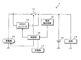
- FIG. 2 is a block diagram showing a main configuration of power supply device 1 according to the first embodiment.
- the power supply device 1 is suitably mounted on a vehicle and includes a generator 10, a switch 11, a DCDC converter 12, a battery 13, a load 14, a current detection circuit 15, a control unit 16, and a storage unit 17.
- One end of the generator 10 is connected to one end of each of the switch 11 and the DCDC converter 12.
- the other ends of the switch 11 and the DCDC converter 12 are connected to the positive electrode of the battery 13 and one end of the load 14.
- the other end of each of the generator 10 and the load 14 and the negative electrode of the battery 13 are grounded.
- the current detection circuit 15 and the storage unit 17 are connected to the control unit 16 separately.
- the generator 10 generates AC power in conjunction with an engine (not shown), rectifies the generated AC power into DC power, and smoothes the rectified power.
- the generator 10 supplies a DC voltage related to the smoothed DC power as an output voltage to the battery 13 and the load 14 via the switch 11.
- the generator 10 further applies an output voltage to one end of the DCDC converter 12.
- the generator 10 has a lowering instruction that instructs the output voltage value to be reduced to a predetermined first output voltage value, for example, 12 V, and the output voltage value is set to a second output voltage value that is higher than the first output voltage value.
- An ascending instruction for instructing raising is input from the control unit 16.
- the generator 10 reduces the output voltage value to the first output voltage value when a decrease instruction is input from the control unit 16, and converts the output voltage value to the second output voltage when the increase instruction is input from the control unit 16. Increase to value.
- the switch 11 is turned on / off by the control unit 16. When the switch 11 is on, the output voltage of the generator 10 is supplied to the battery 13 and the load 14 via the switch 11.
- the DCDC converter 12 transforms the output voltage of the generator 10 applied to one end to a predetermined voltage, and supplies the transformed voltage to the battery 13 and the load 14 from the other end.
- the value of the voltage transformed by the DCDC converter 12 is, for example, 12V.
- the DCDC converter 12 receives an operation instruction for instructing an operation and a stop instruction for instructing an operation stop from the control unit 16.
- the DCDC converter 12 operates when an operation instruction is input from the control unit 16, and stops operating when a stop instruction is input from the control unit 16.
- the output voltage is supplied to the battery 13 from the generator 10 via the switch 11 or the transformed voltage is supplied from the DCDC converter 12. Thereby, the battery 13 stores electricity.
- the load 14 is an electric device mounted on the vehicle.
- the output voltage value of the generator 10 is the second output voltage value, and the switch 11 is off.
- the voltage transformed by the DCDC converter 12 is supplied to the battery 13 and the load 14, and the battery 13 and the load 14 are supplied with power.
- the output voltage value of the generator 10 is the first output voltage value, and the switch 11 is on. At this time, the output voltage of the generator 10 is supplied to the battery 13 and the load 14, and the battery 13 and the load 14 are supplied with power. When the generator 10 stops generating power, the output voltage of the battery 13 is supplied to the load 14 and the load 14 is supplied with power.
- the current detection circuit 15 converts an analog value related to the current flowing to the battery 13 and the load 14 into a digital value, and outputs the converted digital value to the control unit 16.
- the control unit 16 has a CPU (Central Processing Unit) and executes processing by executing a control program stored in a ROM (Read Only Memory) (not shown). Based on the digital value input from the current detection circuit 15, the control unit 16 outputs a decrease instruction / up instruction to the generator 10, turns on / off the switch 11, and operates / stops the DCDC converter 12. The instruction is output.
- a CPU Central Processing Unit
- ROM Read Only Memory
- the storage unit 17 is a non-volatile memory, and the storage unit 17 stores data necessary for the control unit 16 to execute processing. Reading and writing of the contents stored in the storage unit 17 are performed by the control unit 16.
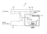
- FIG. 3 is an explanatory diagram of current detection.
- the power supply device 1 further includes a plate-like conductor 18 that connects the other ends of the switch 11 and the DCDC converter 12 to the positive electrode of the battery 13 and one end of the load 14.
- the conductor 18 includes a first conductive part 21, a second conductive part 22, and a third conductive part 23.
- Each of the first conductive portion 21, the second conductive portion 22, and the third conductive portion 23 is a so-called bus bar and has a plate shape.
- FIG. 3 shows the plate surfaces of the first conductive portion 21, the second conductive portion 22, and the third conductive portion 23.
- the first conductive part 21 and the third conductive part 23 are connected to the second conductive part 22.
- the other end of the switch 11 is connected to the third conductive portion 23.
- the other end of the DCDC converter 12 is connected to the first conductive portion 21.
- the positive electrode of the battery 13 and one end of the load 14 are connected to the second conductive portion 22.
- the DCDC converter 12 outputs the transformed voltage to the first conductive unit 21.
- the DCDC converter 12 functions as a transformer.
- the conductor 18 has a first current path through which current flows from the first conductive part 21 to the second conductive part 22 and a second current path through which current flows from the third conductive part 23 to the second conductive part 22.
- the current supplied from the DCDC converter 12 to the load 14 is limited.
- the control unit 16 performs a switching process for switching the current path through which the current flows in the conductor 18 to the first current path or the second current path.
- the control unit 16 changes the current path through which the current flows in the conductor 18 from the first current path to the second current when the value of the current flowing through the first current path is a first current threshold, for example, 100 A or more. Switch to the current path.
- the control unit 16 changes the current path through which the current flows in the conductor 18 from the second current path when the value of the current flowing through the second current path is less than a second current threshold, for example, 90 A. Switch to the first current path.
- the second current threshold is less than or equal to the first current threshold.
- the current detection circuit 15 includes a conducting wire 30, a current sensor 31, and an A / D conversion unit 32.
- the conducting wire 30 is connected between a point P1 located on the surface of the first conductive part 21 and a point P2 located on the surface of the second conductive part 22.
- the current sensor 31 has an annular shape and surrounds the conducting wire 30.
- the A / D conversion unit 32 is connected to the control unit 16 and the current sensor 31 separately. Points P1 and P2 correspond to two points in the claims.
- a current whose value is a first constant of a value of the current flowing through the first current path for example, 1/1000
- a current whose value is a second constant of a value of the current flowing through the second current path for example, 1/2000
- the second constant is larger than the first constant.
- Each of the first constant and the second constant depends on the ratio between the resistance value between the points P1 and P2 in the conductor 18 and the resistance value of the conductive wire 30.
- the second constant further depends on the position of the point P1.
- the second constant is larger as the point P1 is farther from the third conductive portion 23.
- the electrical resistivity of the conductor 18 depends on the temperature value of the conductor 18.
- the electrical resistivity of the conducting wire 30 depends on the temperature value of the conducting wire 30.
- the temperature values of the conductor 18 and the conducting wire 30 are substantially the same.
- the electrical resistivity of each of the conductor 18 and the conducting wire 30 varies in the same manner according to the variation in the temperature values of the conductor 18 and the conducting wire 30.
- the electrical resistivity of the conductor 18 becomes, for example, 1.1 times due to changes in the temperature values of the conductor 18 and the conductor 30, the electrical resistivity of the conductor 30 also becomes 1.1 times. For this reason, the ratio of the electrical resistivity of each of the conductor 18 and the conductor 30 is constant regardless of the temperature values of the conductor 18 and the conductor 30.
- a current whose value is one-first constant of the value of the current flowing through the first current path is independent of the temperature values of the conductor 18 and the conductor 30. It flows to 30.
- a current whose value is a second constant of a value of the current flowing through the second current path is independent of the temperature values of the conductor 18 and the conductor 30. It flows to the conducting wire 30.
- the current sensor 31 outputs a voltage value corresponding to the value of the current flowing through the conducting wire 30 to the A / D converter 32.
- the voltage value output by the current sensor 31 is an analog value, and becomes high / low according to the magnitude of the current flowing through the conducting wire 30.
- the voltage value output by the current sensor 31 depends on the potentials at the points P1 and P2.
- the A / D conversion unit 32 converts the analog voltage value input from the current sensor 31 into a digital voltage value, and outputs the converted digital voltage value to the control unit 16.
- the A / D conversion unit 32 presets the voltage value input from the current sensor 31 by performing processing such as rounding off or rounding down.
- the reference voltage value is quantized to a voltage value that is first or second closest to the voltage value input to the current sensor 31.
- the A / D conversion unit 32 outputs the converted digital voltage value to the control unit 16.
- the digital voltage value output from the A / D conversion unit 32 to the control unit 16 corresponds to a value related to the potential at the points P1 and P2.
- the current sensor 31 outputs an analog voltage value corresponding to the value of the current flowing through the lead wire 30 to the A / D conversion unit 32, and the A / D conversion unit 32 converts the analog voltage value input from the current sensor 31. Converting to a digital voltage value and outputting the converted voltage value corresponds to detecting the value of the current flowing through the conducting wire 30.
- the storage unit 17 includes a first conversion formula for converting the voltage value output from the A / D conversion unit 32 into the value of the current flowing through the first current path, and the voltage output from the A / D conversion unit 32.
- the second conversion formula for converting the value into the value of the current flowing through the second current path is stored.
- the control unit 16 converts the voltage value output from the A / D conversion unit 32 into the value of the current flowing in the first current path or the second current path using the first conversion formula or the second conversion formula.
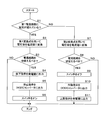
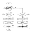
- FIG. 4 is a flowchart showing the switching process executed by the control unit 16.
- the control unit 16 periodically performs the switching process when the generator 10 is generating power.
- the control unit 16 determines whether or not current is flowing through the first current path (step S1).
- the control unit 16 operates the DCDC converter 12 by outputting an operation instruction, and stops the operation of the DCDC converter 12 by outputting a stop instruction.
- the control unit 16 determines that a current is flowing through the first current path.
- the switch 11 is turned on and the operation of the DCDC converter 12 is stopped, the control unit 16 determines that no current is flowing in the first current path.
- the control unit 16 converts the voltage value output from the A / D conversion unit 32 into a current value using the first conversion equation.
- the current value is the value of the current flowing through the first current path.
- the control unit 16 determines whether or not the current path through which the current flows in the conductor 18 should be switched to the second current path (step S3).
- the control unit 16 determines that the current path should be switched to the second current path when the current value converted in step S2 is a first current threshold, for example, 100 A or more.
- the control unit 16 determines that the current path should not be switched to the second current path when the current value converted in step S2 is less than the first current threshold.
- the first current threshold is stored in the storage unit 17 in advance.
- the control unit 16 When it is determined that the current path should be switched to the second current path (S3: YES), the control unit 16 outputs a decrease instruction to the generator 10 (step S4). Thereby, the output voltage value of the generator 10 falls to the first output voltage value, for example, 12V.
- control unit 16 outputs a stop instruction to the DCDC converter 12 (step S5), and turns on the switch 11 (step S6). Thereby, a current flows from one end of the generator 10 to the third conductive part 23 and the second conductive part 22 via the switch 11. In other words, the current path through which current flows in the conductor 18 is switched to the second current path. As described above, the control unit 16 switches the current path through which the current flows from the first current path to the second current path by stopping the operation of the DCDC converter 12 and turning on the switch 11.
- the control unit 16 ends the process after determining that the current path should not be switched to the second current path (S3: NO) or after executing Step S6.
- the control unit 16 determines that no current flows in the first current path, that is, current flows in the second current path (S1: NO)
- the A / D conversion is performed using the second conversion formula.
- the voltage value output by the unit 32 is converted into a current value (step S7).
- the current value is the value of the current flowing through the second current path.
- control unit 16 determines whether or not the current path through which the current flows in the conductor 18 should be switched to the first current path (step S8).
- the control unit 16 determines that the current path should be switched to the first current path when the current value converted in step S7 is less than the second current threshold, for example, 90A.
- the controller 16 determines that the current path should not be switched to the first current path when the current value converted in step S7 is equal to or greater than the second current threshold.
- the second current threshold value is stored in advance in the storage unit 17.
- the control unit 16 When it is determined that the current path should be switched to the first current path (S8: YES), the control unit 16 turns off the switch 11 (step S9) and outputs an operation instruction to the DCDC converter 12 (step S10). Thereby, current flows from one end of the generator 10 to the first conductive part 21 and the second conductive part 22 via the DCDC converter 12. That is, the current path through which current flows in the conductor 18 is switched to the first current path. As described above, the control unit 16 switches the current path through which the current flows from the second current path to the first current path by turning off the switch 11 and operating the DCDC converter 12.
- control part 16 outputs a raise instruction
- the control unit 16 ends the process.
- the control unit 16 uses the current path through which the current flows in the conductor 18 and the current path through which the current flows based on the voltage value output by the A / D conversion unit 32 of the current detection circuit 15. It is determined whether or not to switch.
- the voltage value output by the A / D conversion unit 32 is a value related to the potentials at the points P1 and P2, and corresponds to the current value detected by the current detection circuit 15. Further, the current detection circuit 15, the control unit 16, and the storage unit 17 function as a switching device.
- the voltage value output from the A / D conversion unit 32 of the current detection circuit 15 becomes high / low according to the magnitude of the current flowing through the first current path. It becomes high / low depending on the magnitude of the current flowing through the second current path. Furthermore, the voltage value output from the current sensor 31 when a current having an It value of It flows through the first current path is equal to the voltage value output by the current sensor 31 when a current having the same It value flows through the second current path. Differs from the output voltage value.
- the value of the current flowing through the conducting wire 30 when a current of 100 A flows through the first current path, and the current flowing through the conducting wire 30 when the current of 200 A flows through the second current path are shown.
- the reference voltage value of the A / D converter 32 is set so that the voltage value output from the A / D converter 32 accurately indicates the value of the current flowing through each of the first current path and the second current path. be able to.
- the reference voltage value is set in this way, the current path through which current flows in the conductor 18 can be appropriately switched. Further, since there is no need to configure a circuit for detecting current separately for each of the first current path and the second current path, the switching device according to the first embodiment can be manufactured at low cost.
- control unit 16 is based on the current path through which the current flows and the voltage value output by the A / D conversion unit 32, that is, the current value detected by the current detection circuit 15. It is determined whether or not the current path should be switched. For this reason, the current path is switched with a simple configuration.
- the control unit 16 converts the voltage value output from the A / D conversion unit 32 into the value of the current flowing through the conductor 18.
- the voltage value output from the A / D conversion unit 32 when current flows through the first current path and the voltage value output to the A / D conversion unit 32 when current flows through the second current path are the same.
- a first voltage threshold and a second voltage threshold may be prepared, and the current path may be switched using the first voltage threshold and the second voltage threshold.
- the power supply device 1 according to the second embodiment is different from the power supply device 1 according to the first embodiment in the switching process executed by the control unit 16.
- Other configurations in the second embodiment are the same as those in the first embodiment.
- FIG. 5 is a flowchart showing the switching process executed by the control unit 16 according to the second embodiment. Also in Embodiment 2, the control part 16 performs a switching process periodically, when the generator 10 is generating electric power.
- steps S21 to S29 executed by the control unit 16 in the second embodiment steps S21, S23, S24, S25, S27, S28, and S29 are steps S1, S4 executed by the control unit 16 in the first embodiment. , S5, S6, S9, S10, and S11, the detailed description thereof is omitted.
- the controller 16 determines whether or not the current path through which current flows in the conductor 18 should be switched to the second current path (step S21). S22). The control unit 16 determines that the current path should be switched to the second current path when the digital voltage value output from the A / D conversion unit 32 is equal to or greater than the first voltage threshold. The control unit 16 determines that the current path should not be switched to the second current path when the digital voltage value output from the A / D conversion unit 32 is less than the first voltage threshold.
- the first voltage threshold is a voltage value output by the A / D conversion unit 32 when a current whose value is the first current threshold flows through the first current path.
- the first voltage threshold is stored in the storage unit 17 in advance.
- control unit 16 determines that the current path should be switched to the second current path (S22: YES), it executes Step S23. When it is determined that the current path should not be switched to the second current path (S22: NO), or after executing step S25, the control unit 16 ends the switching process.
- the control unit 16 sets the current path through which the current flows in the conductor 18 to the first current path. It is determined whether or not to switch to the current path (step S26). The control unit 16 determines that the current path should be switched to the first current path when the digital voltage value output from the A / D conversion unit 32 is less than the second voltage threshold. The control unit 16 determines that the current path should not be switched to the second current path when the digital voltage value output from the A / D conversion unit 32 is equal to or greater than the second voltage threshold.
- the second voltage threshold is a voltage value output by the A / D conversion unit 32 when a current whose value is the second current threshold flows through the second current path.
- the second voltage threshold is stored in the storage unit 17 in advance. Since the second current threshold is less than or equal to the first current threshold, the second voltage threshold is less than or equal to the first voltage threshold.
- Step S27 When the control unit 16 determines that the current path should be switched to the first current path (S26: YES), the control unit 16 executes Step S27. When it is determined that the current path should not be switched to the first current path (S26: NO), or after executing step S29, the control unit 16 ends the switching process.
- the control unit 16 is based on the current path through which current is flowing in the conductor 18 and the voltage value output by the A / D conversion unit 32 of the current detection circuit 15. It is determined whether or not the current path through which the current flows should be switched.
- the configuration other than the switching process executed by the control unit 16 is the same as that of the first embodiment. For this reason, in the second embodiment, the switching device including the current detection circuit 15, the control unit 16, and the storage unit 17 has the same effect as the first embodiment.
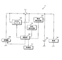
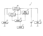
- FIG. 6 is a block diagram showing a main configuration of the power supply device 1 according to the third embodiment.
- the power supply device 1 in the third embodiment includes a generator 10, a switch 11, a DCDC converter 12, a battery 13, a load 14, a current detection circuit 15, a control unit 16, and a storage unit 17, which are the same as those in the first embodiment. It is connected to the.
- the power supply device 1 according to the third embodiment further includes a temperature detection circuit 19, and the temperature detection circuit 19 is connected to the control unit 16.
- the power supply device 1 according to the third embodiment differs from the power supply device 1 according to the first embodiment in that the temperature detection circuit 19 is provided and the current detection circuit 15 is configured.
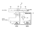
- FIG. 7 is an explanatory diagram of current detection.
- the first conductive portion 21 and the third conductive portion 23 are connected to the second conductive portion 22, respectively.
- the first conductive portion 21, the second conductive portion 22, and the third conductive portion 23 are conductors.
- 18 is constituted.
- the temperature detection circuit 19 detects the temperature value of the conductor 18.
- the temperature detection circuit 19 includes a temperature sensor (not shown), an A / D conversion unit, and the like, and outputs the detected digital temperature value to the control unit 16.
- the temperature detection circuit 19 functions as a temperature detection unit.
- the current detection circuit 15 in the third embodiment includes an A / D conversion unit 32 and a differential amplifier 40 similar to those in the first embodiment.
- the plus terminal is connected to the point P1 located on the surface of the first conductive part 21, and the minus terminal is connected to the point P2 located on the surface of the second conductive part 22.
- the output terminal of the differential amplifier 40 is connected to the A / D converter 32.
- the A / D conversion unit 32 is further connected to the control unit 16.
- the differential amplifier 40 amplifies the voltage value between the points P1 and P2, and outputs the amplified analog voltage value to the A / D conversion unit 32.
- the A / D converter 32 converts the analog voltage value input from the differential amplifier 40 into a digital voltage value, and outputs the converted digital voltage value to the controller 16.
- the A / D conversion unit 32 performs a process such as rounding off or rounding down to set a voltage value input from the differential amplifier 40 in advance.
- the reference voltage value is quantized to a voltage value that is first or second closest to the voltage value input from the differential amplifier 40.
- the A / D conversion unit 32 outputs the converted digital voltage value to the control unit 16.
- the voltage value between the points P3 and P2 increases as the current value flowing through the second current path increases, and decreases as the current value flowing through the second current path decreases. .
- the voltage value between the points P1 and P2 is larger as the value of the current flowing through the second current path is larger, and smaller as the value of the current flowing through the second current path is smaller.
- the voltage value between the points P1 and P2 increases as the value of the current flowing through the first current path increases, and decreases as the value of the current flowing through the first current path decreases.
- the voltage value between the points P1 and P2 when the current having the current value It flows through the first current path is the point between the points P1 and P2 when the current having the same current value flows through the second current path. Higher than the voltage value.
- the digital voltage value output from the A / D conversion unit 32 to the control unit 16 corresponds to a value related to the potential at the points P1 and P2.
- the differential amplifier 40 amplifies the voltage value between the points P1 and P2, outputs the amplified analog voltage value to the A / D conversion unit 32, and the A / D conversion unit 32 receives the analog input from the differential amplifier 40. Converting the voltage value into a digital voltage value and outputting the converted voltage value corresponds to detecting the voltage between the points P1 and P2.
- the control unit 16 executes the same switching process as in the first embodiment. However, the specific conversion configuration performed in steps S2 and S7 is different from that of the first embodiment.
- the voltage value output from the A / D conversion unit 32 of the current detection circuit 15 to the control unit 16 and the temperature detection The temperature value output from the circuit 19 to the control unit 16 is a variable.
- Step S2 the control unit 16 converts the voltage value output from the A / D conversion unit 32 into a current value by using the first conversion formula into which the temperature value output from the temperature detection circuit 19 is substituted.
- the current value is the value of the current flowing in the first current path.
- the control unit 16 in the third embodiment determines that no current flows through the first current path, that is, current flows through the second current path (S1: NO)
- the temperature detection circuit 19 Is substituted into the second conversion equation, and then step S7 is executed.
- step S7 the control unit 16 converts the voltage value output from the A / D conversion unit 32 into a current value by using the second conversion formula into which the temperature value output from the temperature detection circuit 19 is substituted.
- the current value is the value of the current flowing in the second current path.
- the electrical resistivity of the conductor 18 is higher as the temperature value of the conductor 18 is higher.
- the current value converted in step S2 or S7 is smaller as the temperature value of the conductor 18 is higher and larger as the temperature value of the conductor 18 is lower.
- the current sensor 31 outputs a voltage value corresponding to the value of the current flowing through the conducting wire 30, and the A / D converter 32 converts the analog voltage value output from the current sensor 31 into a digital voltage value. Convert.
- the differential amplifier 40 amplifies the voltage value between the points P1 and P2, outputs the amplified voltage value, and the A / D converter 32 outputs the analog output from the differential amplifier 40. Is converted to a digital voltage value. For this reason, each of the first conversion formula and the second conversion formula in the third embodiment is different from the first conversion formula and the second conversion formula in the first embodiment.
- the control unit 16 detects the current path through which the current flows in the conductor 18, the voltage value output by the A / D conversion unit 32 of the current detection circuit 15, and the temperature detected by the temperature detection circuit 19. Whether or not the current path through which the current flows should be switched is determined based on the value.
- the voltage value output by the A / D conversion unit 32 is a value related to the potential at the points P1 and P2, and corresponds to the voltage value detected by the current detection circuit 15.
- the current detection circuit 15, the control unit 16, the storage unit 17, and the temperature detection circuit 19 function as a switching device.
- the voltage value output from the A / D converter 32 of the current detection circuit 15 becomes high / low according to the magnitude of the current flowing through the first current path, and the value of the current flowing through the second current path is large. / High / low depending on small.
- the voltage value output from the differential amplifier 40 when the current having the current value It flows through the first current path is the differential value when the current having the same current value flows through the second current path. It is different from the voltage value output from the amplifier 40.
- the voltage value between points P1 and P2 when a current of 100 A flows in the first current path and the voltage value between points P1 and P2 when a current of 200 A flows in the second current path.
- the voltage value can be matched.
- the reference voltage value of the A / D converter 32 is set so that the voltage value output from the A / D converter 32 accurately indicates the value of the current flowing through each of the first current path and the second current path. be able to.
- the reference voltage value is set in this way, the current path through which current flows in the conductor 18 can be appropriately switched. Further, since there is no need to configure a circuit for detecting current separately for each of the first current path and the second current path, the switching device according to the first embodiment can be manufactured at low cost.
- control unit 16 is based on the current path through which the current flows and the voltage value output by the A / D conversion unit 32, that is, the voltage value detected by the current detection circuit 15. It is determined whether or not the current path should be switched. For this reason, the current path is switched with a simple configuration. Further, the control unit 16 detects not only the current path through which the current flows and the voltage value detected by the current detection circuit 15 but also the temperature value output by the temperature detection circuit 19, that is, the temperature detection circuit 19 detects the current value. It is determined whether or not the current path should be switched based on the measured temperature value. For this reason, the current path through which the current flows in the conductor 18 is more appropriately switched.
- the ratio of the electrical resistivity of the conductor 18 and the conductor 30 depends on the temperature value of the conductor 18 and the conductor 30. To do. In the first embodiment, for example, since the materials used for the conductor 18 and the conductor 30 are different, the relationship between the temperature value and the electrical resistivity is different between the conductor 18 and the conductor 30. The ratio of the electrical resistivity of each of the body 18 and the conductor 30 depends on the temperature values of the conductor 18 and the conductor 30.
- the switching device in the first embodiment includes the temperature detection circuit 19 as in the third embodiment, and the A / D conversion unit 32 of the current detection circuit 15 is controlled by the control unit 16.
- the first conversion equation and the second conversion equation may be used in which the voltage value output to and the temperature value output from the temperature detection circuit 19 to the control unit 16 are variables.
- the switching device in the first embodiment includes a temperature detection circuit that detects the temperature values of the conductor 18 and the conductor 30, and the value of the current flowing through the conductor 30.
- the first conversion formula and the second conversion formula in which the temperature values of the conductor 18 and the conductive wire 30 are variables may be used.
- control unit 16 executes the switching process in the first embodiment.
- the switching process executed by the control unit 16 is not limited to the switching process in the first embodiment, and the same switching process as in the second embodiment may be executed.
- the switching process executed by the control unit 16 is different from that of the power supply device 1 according to the third embodiment.
- the control unit 16 in the fourth embodiment executes the same switching process as in the second embodiment.
- the configuration of determination performed in steps S22 and S26 is different from that of the second embodiment.
- the first voltage threshold used in step S ⁇ b> 22 varies depending on the temperature value output from the temperature detection circuit 19 to the control unit 16.
- the second voltage threshold value used in step S27 also differs depending on the temperature value output from the temperature detection circuit 19 to the control unit 16.
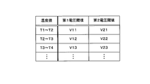
- FIG. 8 is a chart showing the first voltage threshold and the second voltage threshold in the fourth embodiment.
- the first voltage threshold value and the second voltage threshold value are associated with the temperature value output from the temperature detection circuit 19 to the control unit 16.
- the storage unit 17 stores a relationship between the temperature value and the first voltage threshold value, and a relationship between the temperature value and the second voltage threshold value.
- T1, T2, T3, T4 are temperature values, and V11, V12, V13... And V21, V22, V23,.
- T1 ⁇ T2 ⁇ T3 ⁇ T4 holds.
- the first voltage threshold and the second voltage threshold are V11 and V21, respectively.
- the first voltage threshold and the second voltage threshold are V12 and V22, respectively.
- the first voltage threshold and the second voltage threshold are V13 and V23, respectively.
- the control unit 16 in the fourth embodiment corresponds to the temperature value output from the temperature detection circuit 19 to the control unit 16 when it is determined that the current is flowing through the first current path (S21: YES).
- the first voltage threshold value is read from the storage unit 17, and then Step S22 is executed.
- the control unit 16 determines that the current path should be switched to the second current path when the digital voltage value output from the A / D conversion unit 32 is equal to or greater than the read first voltage threshold value.
- the control unit 16 determines that the current path should not be switched to the second current path when the digital voltage value output from the A / D conversion unit 32 is less than the read first voltage threshold.
- the first voltage threshold value is a voltage value output by the A / D conversion unit 32 when a current whose value is the first current threshold value flows in the first current path.
- step S ⁇ b> 26 the control unit 16 determines that the current path should be switched to the first current path when the digital voltage value output from the A / D conversion unit 32 is less than the read second voltage threshold.
- the control unit 16 determines that the current path should not be switched to the first current path when the digital voltage value output from the A / D conversion unit 32 is equal to or greater than the read second voltage threshold.
- the second voltage threshold is a voltage value output by the A / D conversion unit 32 when a current whose value is the second current threshold flows through the second current path.
- the control unit 16 detects the current path through which the current flows in the conductor 18, the voltage value output by the A / D conversion unit 32 of the current detection circuit 15, and the temperature detection. Based on the temperature value detected by the circuit 19, it is determined whether or not the current path through which the current flows should be switched.
- the configuration other than the switching process executed by the control unit 16 and the correspondence relationship shown in FIG. 8 stored in the storage unit 17 is the same as that of the third embodiment. Therefore, in the fourth embodiment, the switching device including the current detection circuit 15, the control unit 16, the storage unit 17, and the temperature detection circuit 19 has the same effect as that of the third embodiment.
- the switching device when the temperature value of the conductor 18 is different from the temperature value of the conductor 30 or when the relationship between the temperature value and the electrical resistivity is different between the conductor 18 and the conductor 30, the conductor The ratio of the electrical resistivity of each of 18 and the conductor 30 depends on the temperature values of the conductor 18 and the conductor 30.
- the switching device includes a temperature detection circuit 19 as in the fourth embodiment, and the relationship between the temperature value and the first voltage threshold, the temperature value, The relationship with the second voltage threshold value may be stored in the storage unit 17.
- step S22 when the control unit 16 determines that the current is flowing through the first current path (S21: YES), the control unit 16 sets the temperature value output to the control unit 16 by the temperature detection circuit 19. The corresponding first voltage threshold value is read from the storage unit 17, and then step S22 is executed. Further, when the control unit 16 determines that no current flows through the first current path, that is, current flows through the second current path (S21: NO), the temperature detection circuit 19 outputs to the control unit 16. The second voltage threshold value corresponding to the temperature value thus read is read from the storage unit 17, and then step S26 is executed.
- the switching device in the first embodiment includes a temperature detection circuit that detects the temperature values of the conductor 18 and the conductor 30, and each of the conductor 18 and the conductor 30.
- the relationship between the temperature value and the first voltage threshold value and the relationship between the temperature value of each of the conductor 18 and the conductive wire 30 and the second temperature value may be stored in the storage unit 17.
- the configuration for determining the first voltage threshold or the second voltage threshold is not limited to the configuration in which the storage unit 17 reads the first voltage threshold or the second voltage threshold associated with the temperature value.
- a relational expression between the first voltage threshold (or the second voltage threshold) and the temperature value detected by the temperature detection circuit 19 may be stored in the storage unit 17.
- the control unit 16 calculates the first voltage threshold (or the second voltage threshold) by substituting the temperature value detected by the temperature detection circuit 19 into the above-described relational expression, and calculates the calculated first The voltage threshold (or second voltage threshold) is used in step S22 (or step 26).
- the configuration for determining the first voltage threshold or the second voltage threshold is that the storage unit 17 associates with the temperature value.
- the configuration is not limited to reading the first voltage threshold or the second voltage threshold.
- the conductor 18 further includes a resistance portion having a lower conductivity than any of the first conductive portion 21, the second conductive portion 22, and the third conductive portion 23 so that the resistance value between the points P1 and P2 is increased. May be.
- the configuration of the conductor 18 and the object to be detected by the temperature detection circuit 19 are different from those in the power supply device 1 in the third embodiment.
- FIG. 9 is an explanatory diagram of current detection in the fifth embodiment.
- the conductor 18 in the fifth embodiment includes a resistance unit 50 in addition to the first conductive unit 21, the second conductive unit 22, and the third conductive unit 23.
- the resistance portion 50 has a rectangular plate shape.
- An end portion of the third conductive portion 23 is connected to one side of the resistor portion 50, and an end portion of the second conductive portion 22 is connected to one side of the resistor portion 50 facing the one side.
- One side of the first conductive unit 21 is connected to one side of the other two sides of the resistance unit 50 except for the two sides to which the second conductive unit 22 and the third conductive unit 23 are connected.
- each of the first conductive portion 21 and the third conductive portion 23 is connected to the second conductive portion 22 via the resistance portion 50.
- FIG. 9 shows the plate surfaces of the first conductive portion 21, the second conductive portion 22, the third conductive portion 23, and the resistance portion 50.
- the point P1 is located at the connecting portion of the first conductive part 21 and the resistor part 50. Further, the point P ⁇ b> 2 is located at a connection portion between the second conductive portion 22 and the resistance portion 50.
- the temperature detection circuit 19 in the fifth embodiment detects the temperature value of the resistance unit 50.
- the temperature detection circuit 19 includes a temperature sensor (not shown), an A / D conversion unit, and the like, and outputs the detected digital temperature value to the control unit 16.
- the conductor 18 in the fifth embodiment when a current flows through the first current path, the current flows in the order of the first conductive portion 21, the resistance portion 50, and the second conductive portion 22. Further, in the conductor 18 according to the fifth embodiment, when a current flows through the second current path, the current flows in the order of the third conductive portion 23, the resistor portion 50, and the second conductive portion 22.
- the equipotential lines shown in FIG. 7 and FIG. 9 are equipotential lines when currents having the same value flow through the second current path in the third and fifth embodiments.
- the voltage difference between adjacent equipotential lines in FIG. 9 is the same as the voltage difference between adjacent equipotential lines in FIG.
- the conductivity of the resistance unit 50 is lower than any of the conductivity of the first conductive unit 21, the second conductive unit 22, and the third conductive unit 23. For this reason, when a current flows through the second current path as indicated by a solid arrow in FIG. 9, the voltage is greatly decreased between the points P ⁇ b> 1 and P ⁇ b> 2 by the resistance unit 50. This can also be seen from the fact that the number of equipotential lines in FIG. 9 between the points P3 and P2 is larger than the number of equipotential lines in FIG. 7 between the points P3 and P2.
- the voltage value between the points P1 and P2 increases as the value of the current flowing through the second current path increases as in the third embodiment. The smaller the value of the flowing current, the smaller.
- the voltage value between the points P1 and P2 increases as the value of the current flowing through the first current path increases, and the value of the current flowing through the first current path decreases. Small enough.
- the voltage value between the points P1 and P2 when the current having the current value It flows in the first current path is the same as the current value It in the second current path. Is larger than the voltage value between the points P1 and P2.
- the control unit 16 in the fifth embodiment performs a switching process similar to that in the third embodiment. However, since the temperature detection circuit 19 detects the temperature value of the resistance unit 50 as described above, the temperature value substituted into the first conversion formula and the second conversion formula before executing steps S2 and S7 is the resistance value. This is the temperature value of the part 50.
- the conductor 18 has a resistance unit 50. Furthermore, since the temperature value substituted into the first conversion formula and the second conversion formula is the temperature value of the resistance unit 50, it is stored in the storage unit 17 in the fifth embodiment. Each of the first conversion formula and the second conversion formula being performed is different from the first conversion formula and the second conversion formula stored in the storage unit 17 in the third embodiment.
- the current value converted in step S2 or S7 is smaller as the temperature value of the resistance unit 50 is higher and larger as the temperature value of the resistance unit 50 is lower.
- control unit 16 is configured to detect the current path through which the current flows in the conductor 18, the voltage value output by the A / D conversion unit 32 of the current detection circuit 15, and the temperature detection. Based on the temperature value detected by the circuit 19, it is determined whether or not the current path through which the current flows should be switched.
- the current detection circuit 15, the control unit 16, the storage unit 17, and the temperature detection circuit 19 function as a switching device.
- the voltage value output from the A / D converter 32 of the current detection circuit 15 becomes high / low according to the magnitude of the current flowing through the first current path, and the value of the current flowing through the second current path is large. / High / low depending on small.
- the voltage value output from the differential amplifier 40 when the current having the current value It flows through the first current path is the differential value when the current having the same current value flows through the second current path. It is different from the voltage value output from the amplifier 40.
- the voltage value can be matched.
- the reference voltage value of the A / D converter 32 is set so that the voltage value output from the A / D converter 32 accurately indicates the value of the current flowing through each of the first current path and the second current path. be able to.
- the reference voltage value is set in this way, the current path through which current flows in the conductor 18 can be appropriately switched. Further, since there is no need to configure a circuit for detecting current separately for each of the first current path and the second current path, the switching device according to the first embodiment can be manufactured at low cost.
- control unit 16 is based on the current path through which the current flows and the voltage value output by the A / D conversion unit 32, that is, the voltage value detected by the current detection circuit 15. It is determined whether or not the current path should be switched. For this reason, the current path is switched with a simple configuration. Further, the control unit 16 detects not only the current path through which the current flows and the voltage value detected by the current detection circuit 15 but also the temperature value output by the temperature detection circuit 19, that is, the temperature detection circuit 19 detects the current value. It is determined whether or not the current path should be switched based on the measured temperature value. For this reason, the current path through which the current flows in the conductor 18 is more appropriately switched.
- the control unit 16 determines whether or not the current path should be switched in the switching process. Furthermore, it can determine appropriately.
- the storage unit 17 may be configured similarly to the fourth embodiment, and the control unit 16 may execute the switching process in the fourth embodiment.
- the temperature value output from the temperature detection circuit 19 to the control unit 16 is not the temperature value of the conductor 18 but the temperature value of the resistance unit 50 as described above. Therefore, the first voltage threshold values V11, V12, V13,... And the second voltage threshold values V21, V22,... Stored in the storage unit 17 in association with the temperature values output from the temperature detection circuit 19 to the control unit 16 are stored. V23,... Are different from the fourth embodiment.
- control unit 16 in the fifth embodiment executes the switching process in the fourth embodiment, the same effects as those in the fifth embodiment described above are obtained.
- the position of the point P1 is not limited to the connecting portion between the first conductive portion 21 and the resistance portion 50, and may be the surface of the first conductive portion 21.
- the position of the point P ⁇ b> 2 is not limited to the connection portion between the second conductive portion 22 and the resistance portion 50, and may be on the surface of the second conductive portion 22.
- the shape of the resistance portion 50 is not limited to a rectangular plate shape, and may be, for example, a T shape or an L shape.
- one side to which the first conductive unit 23 is connected may not face the one side to which the second conductive unit 22 is connected.
- the first conductive part 21 and the third conductive part 23 may be connected to the second conductive part 22 via the resistance part 50.
- the switching device in the first embodiment includes the temperature detection circuit 19 or the temperature detection circuit that detects the temperature values of the conductor 18 and the conductor 30, the conductor 18 in the fifth embodiment is used. It may be done.
- the switching device according to the second embodiment includes the temperature detection circuit 19 or the temperature detection circuit that detects the temperature values of the conductor 18 and the conductor 30, the conductor 18 according to the fifth embodiment. May be used.
- the control unit 16 switches the path of the current flowing in the conductor 18 by controlling the on / off of the switch 11 and the operation / stop of the DCDC converter 12.
- another DCDC converter is used instead of the switch 11, and the control unit 16 controls the operation / stop of the DCDC converter and the operation / stop of the DCDC converter 12, whereby a current flows in the conductor 18.
- the current path may be switched.
- FIG. 10 is a block diagram showing a main configuration of the power supply device 1 according to the sixth embodiment.
- the power supply device 1 in the sixth embodiment includes a generator 10, a DCDC converter 12, a battery 13, a load 14, a current detection circuit 15, a control unit 16, and a storage unit 17, which are connected in the same manner as in the first embodiment. ing.
- the power supply device 1 according to the sixth embodiment further includes a DCDC converter 60. One end of the DCDC converter 60 is connected to one end of the generator 10, and the other end of the DCDC converter 60 is connected to the positive electrode of the battery 13 and one end of the load 14.
- the DCDC converter 60 transforms the output voltage of the generator 10 applied to one end into a predetermined voltage, and supplies the transformed voltage to the battery 13 and the load 14 from the other end.
- the value of the voltage transformed by the DCDC converter 60 is, for example, 12V.
- the DCDC converter 60 receives an operation instruction and a stop instruction from the control unit 16.
- the DCDC converter 60 operates when an operation instruction is input from the control unit 16, and stops operating when a stop instruction is input from the control unit 16.
- the other DCDC converter stops operating.
- the transformed voltage is supplied to the battery 13 and the load 14 from one of the DCDC converters 12 and 60.
- the battery 13 stores power and the load 14 is supplied with power.
- the generator 10 stops generating power
- the load 14 is supplied with power by the battery 13.
- the DCDC converter 60 may flow a current equal to or higher than this upper limit value.
- the first current threshold is less than the upper limit value.
- the second current threshold is less than or equal to the first current threshold.
- the conductor 18 connects the other ends of the DCDC converters 12 and 60 to the positive electrode of the battery 13 and one end of the load 14. More specifically, the other end of the DCDC converter 12 is connected to the first conductive portion 21, and the other end of the DCDC converter 60 is connected to the third conductive portion 23. The positive electrode of the battery 13 and one end of the load 14 are connected to the second conductive portion 22.
- the control unit 16 executes the same switching process as in the first embodiment.
- step S6 of the switching process in the first embodiment, the control unit 16 outputs an operation instruction to the DCDC converter 60 instead of turning on the switch 11.
- step S9 the control unit 16 outputs a stop instruction to the DCDC converter 60 instead of turning off the switch 11.
- the control unit 16 outputs a stop instruction to the DCDC converter 12 and outputs an operation instruction to the DCDC converter 60.
- the DCDC converter 12 stops operating and the DCDC converter 60 operates, so that the current path through which the current flows in the conductor 18 is switched from the first current path to the second current path.
- the control unit 16 outputs a stop instruction to the DCDC converter 60 and outputs an operation instruction to the DCDC converter 12.
- the DCDC converter 60 stops operating and the DCDC converter 12 operates, so that the current path through which the current flows in the conductor 18 is switched from the second current path to the first current path.
- the control unit 16 outputs the operation instruction or the stop instruction to the DCDC converters 12 and 60 separately to switch the current path through which the current flows in the conductor 18.
- the control unit 16 in the sixth embodiment determines whether or not the current path through which the current flows in the conductor 18 should be switched, similarly to the control unit 16 in the first embodiment. Therefore, in the sixth embodiment, the switching device including the current detection circuit 15, the control unit 16, and the storage unit 17 has the same effect as that of the first embodiment.
- the power supply device 1 may include a DCDC converter 60 instead of the switch 11 as in the sixth embodiment.
- the control unit 16 switches the current path through which the current flows in the conductor 18 as in the sixth embodiment.
- each of the first conductive portion 21, the second conductive portion 22, and the third conductive portion 23 is not limited to a bus bar, and may be a conductor in a printed wiring board, for example.
- the control unit 16 and the temperature detection circuit 19 are configured separately. However, the control unit 16 and the temperature detection circuit 19 may be integrally configured.
Landscapes
- Engineering & Computer Science (AREA)
- Power Engineering (AREA)
- Physics & Mathematics (AREA)
- Automation & Control Theory (AREA)
- Radar, Positioning & Navigation (AREA)
- General Physics & Mathematics (AREA)
- Electromagnetism (AREA)
- Combustion & Propulsion (AREA)
- General Engineering & Computer Science (AREA)
- Mechanical Engineering (AREA)
- Chemical & Material Sciences (AREA)
- Theoretical Computer Science (AREA)
- Dc-Dc Converters (AREA)
- Control Of Voltage And Current In General (AREA)
- Electric Propulsion And Braking For Vehicles (AREA)
- Measurement Of Current Or Voltage (AREA)
Abstract
導電体18を流れる電流経路として、第1導電部21から第2導電部22へ電流が流れる第1電流経路と、第3導電部23から第2導電部22へ電流が流れる第2電流経路とがある。第1導電部21、第2導電部22及び第3導電部夫々は板状をなし、第1導電部21の板面に点P1が位置し、第2導電部22の板面に点P2が位置する。電流検出回路15では、点P1,P2間の電位差に係る値を検出し、第1電流経路及び第2電流経路夫々に流れる電流値に応じた電圧値を出力する。
Description
本発明は、電流経路に流れる電流値に応じた電圧値を出力する電流検出回路と、該電流検出回路を備える電流検出装置と、電流が流れる電流経路を前記電流検出回路が出力した電圧値に応じて切替える切替え装置とに関する。
現在、車両に搭載される電源装置として、2つの電流経路を介して負荷への給電が行われる電源装置(例えば特許文献1を参照)が提案されている。
特許文献1に記載の電源装置では、2つの電流経路中の一方の電流経路にDCDCコンバータが設けられている。DCDCコンバータは、印加された電圧を変圧し、変圧した電圧を負荷に与える。これにより、負荷が給電される。他方の電流経路にはDCDCコンバータが設けられておらず、直接に負荷に給電される。特許文献1の電源装置では、負荷への給電に用いられる電流経路が前述した2つの電流経路中のいずれかに切替えられる。
図1は従来の電源装置8の要部構成を示すブロック図である。従来の電源装置8では、発電機80の一端が、スイッチ81及びDCDCコンバータ82夫々の一端に接続されており、スイッチ81及びDCDCコンバータ82夫々の他端は、抵抗R8の一端に接続されている。抵抗R8の他端は負荷83の一端に接続されている。発電機80及び負荷83夫々の他端は接地されている。抵抗R8の一端及び他端夫々は、差動増幅器84のプラス端子及びマイナス端子に接続され、差動増幅器84の出力端子はA/D(Analog/Digital)変換部85に接続されている。A/D変換部85は更に制御部86に接続されている。
制御部86は、スイッチ81のオン/オフと、DCDCコンバータ82の作動/停止とを制御する。制御部86がスイッチ81をオフにしてDCDCコンバータ82を作動させている場合、DCDCコンバータ82は、発電機80が出力した直流の出力電圧を降圧し、降圧した電圧を、抵抗R8を介して、負荷83に供給する。また、制御部86がスイッチ81をオンにしてDCDCコンバータ82の動作を停止させている場合、発電機80は、出力電圧を、スイッチ81及び抵抗R8を介して負荷83に供給する。
差動増幅器84は、抵抗R8の両端間の電圧値を増幅し、増幅したアナログの電圧値をA/D変換部85に出力する。抵抗R8に流れる電流の値が大きい程、差動増幅器84の出力電圧値は大きい。A/D変換部85は、アナログの電圧値をデジタルの電圧値に変換し、変換したデジタルの電圧値を制御部86に出力する。抵抗R8の両端間の電圧値は、抵抗R8に流れる電流の値に比例するので、抵抗R8、差動増幅器84及びA/D変換部85は電流検出回路として機能する。
制御部86は、通常、スイッチ81をオフにし、DCDCコンバータ82を作動させている。DCDCコンバータ82を介して流すことが可能な電流の値は所定値に制限されている。そこで、所定値未満である第1電流値と、第1電流値以下である第2電流値が設定されている。スイッチ81がオフであってDCDCコンバータ82が作動している場合において、抵抗R8に流れる電流が第1電流値以上となってA/D変換部85が出力した電圧値が第1電圧値以上となったとき、制御部86は、DCDCコンバータ82の動作を停止させてスイッチ81をオンにする。これにより、発電機80から負荷83に流れる電流の電流経路が、DCDCコンバータ82を介して電流が流れる第1経路から、スイッチ81を介して電流が流れる第2経路に切替わる。このように、制御部86が電流経路を切替えるので、負荷83が所定値以上の電流の供給を必要とする場合であっても、負荷83に電流を供給し続けることができる。
スイッチ81がオンであってDCDCコンバータ82の動作が停止している場合において、第2経路に流れる電流の値が第2電流値未満となってA/D変換部85が出力した第2電圧値未満になったとき、制御部86は、スイッチ81をオフにしてDCDCコンバータ82を作動させる。これにより、発電機80から負荷83に流れる電流の電流経路が第2経路から第1経路に切替わる。負荷83にはDCDCコンバータ82が降圧した電圧が再び供給される。前述した電流検出回路と制御部86とは、電流が流れる電流経路を第1経路又は第2経路に切替える切替え装置として機能する。
A/D変換部85は、四捨五入又は切り捨て等の処理を行って、基準電圧値を所定数で等分した電圧値の中で、差動増幅器84が出力した電圧値に1番目又は2番目に近い電圧値に、差動増幅器84が出力した電圧値を量子化する。前述したように電流経路が切替わる従来の電源装置8においては、第1経路に第1電流値未満の電流が流れ、第2経路に第2電流値以上の電流が流れる。第2経路は第1電流値以上の電流を流すために設けられているので、第2経路には第1電流値以上の電流が流れる。
例えば、従来の電源装置8において第1経路にゼロ~100Aの電流が流れ、第2経路に90~200Aの電流が流れる場合、抵抗R8には、ゼロ~200Aの電流が流れる。抵抗R8に200Aの電流が流れた場合に差動増幅器84が出力する電圧値が10Vであるとき、差動増幅器84が出力する電圧値はゼロ~10Vの範囲で変動する。このため、A/D変換部85の基準電圧値は10V以上に設定される。基準電圧値が10Vであって、A/D変換部85が電圧値を10ビットのデジタル値に変換する場合、A/D変換部85は、10V(基準電圧値)を1023(所定数)で等分した電圧値の中で、差動増幅器84が出力した電圧値に1番目又は2番目に近い電圧値に、差動増幅器84が出力した電圧値を量子化する。このとき、目盛の間隔は約9.78mVである。
第1経路を流れる電流の値はゼロ~100Aの範囲で変動する。第1経路を流れる電流の値のみを検出する構成を考える。抵抗R8に100Aの電流が流れた場合に差動増幅器84が出力する電圧値が5Vであるとき、A/D変換部85の基準電圧値を5Vに設定することができる。このとき、A/D変換部85は、5V(基準電圧値)を1023(所定数)で等分した電圧値の中で、差動増幅器84が出力した電圧値に1番目又は2番目に近い電圧値に、差動増幅器84が出力した電圧値を量子化する。このとき、目盛の間隔は約4.89mVである。基準電圧値が5Vである場合、目盛の間隔が小さいため、抵抗R8、差動増幅器84及びA/D変換部85によって構成される電流検出回路は第1経路を流れる電流の値を高精度に検出することができる。
しかしながら、従来の電源装置8に搭載されている電流検出回路においては、第2経路に流れる電流の最大値に応じて、A/D変換部85の基準電圧値が設定されるため、第1経路に流れる電流値を高精度に検出することができないという問題がある。この場合、適切に電流経路を切替えることができない虞がある。
この問題を解決するために、抵抗、差動増幅器及びA/D変換部夫々の数を2つに増やし、第1経路及び第2経路を流れる電流値を各別に検出する構成が考えられる。しかしながら、この構成では、部品点数が多いため、製造費用が嵩むという問題がある。
本発明は斯かる事情に鑑みてなされたものであり、その目的とするところは、2つの電流経路夫々に流れる電流値を正確に示す電圧値を出力することが可能である安価な電流検出回路、並びに、該電流検出回路を備える電流検出装置及び切替え装置を提供することにある。
本発明に係る電流検出回路は、第1導電板から第2導電板への第1電流経路、及び、第3導電板から前記第2導電板への第2電流経路夫々に流れる電流値に応じた電圧値を出力する電流検出回路において、前記第1導電板及び第2導電板の板面に位置する2点間の電位差に係る値を検出する電位差検出部を備えることを特徴とする。
本発明にあっては、第1導電板から第2導電板への第1電流経路、又は、第3導電板から第2導電板への第2電流経路に電流が流れる。第1導電板の板面に位置する点と第3導電板の板面に位置する点との電位差に係る値を検出する。
2点間の電位差に係る値は、第1電流経路に流れる電流値と、第2電流経路に流れる電流値とに応じて変動する。そして、第2電流経路に、ある値の電流が流れている場合に検出される2点間の電位差に係る値は、第1電流経路に同じ値の電流が流れている場合に検出される2点間の電位差に係る値と異なる。
2点間の電位差に係る値は、2点間の電圧値、又は、2点間を流れる電流値等である。回路から出力される電圧値は、2点間の電圧値、又は、2点間を流れる電流値に基づく電圧値である。本発明では、例えば、第1電流経路に100Aの電流が流れた場合における2点間の電位差に係る値と、第2電流経路に200Aの電流が流れた場合における2点間の電位差に係る値とを一致させることができる。この場合、第1電流経路及び第2電流経路夫々を流れる電流値を正確に示す電圧値が出力される。また、2点間の電位差に係る値を検出する構成の数は1つでよいため、製造費用が安価である。
本発明に係る電流検出回路は、前記2点間に接続してある導線を備え、前記電位差検出部は該導線を流れる電流値を検出することを特徴とする。
本発明にあっては、第1導電板の板面に位置する点と第2導電板の板面に位置する点との間に接続してある導線に流れる電流値を検出する。
本発明に係る電流検出回路は、前記電位差検出部は前記2点間の電圧値を検出することを特徴とする。
本発明にあっては、第1導電板の板面に位置する点と第2導電板の板面に位置する点との間の電圧値を検出する。
本発明に係る電流検出回路は、前記第1導電板及び第3導電板夫々は、前記第1導電板、第2導電板及び第3導電板よりも導電率が低い抵抗部を介して、前記第2導電板に連なっていることを特徴とする。
本発明にあっては、第1導電板及び第3導電板夫々は、第1導電板、第2導電板及び第3導電板よりも導電率が低い抵抗部を介して第2導電板に連なっている。このため、第1導電板の板面に位置する点と第2導電板の板面に位置する点との間の電圧値が大きい。
本発明に係る電流検出装置は、前述した電流検出回路と、前記第1導電板及び第3導電板夫々が前記第2導電板に連なることによって構成された導電体の温度値を検出する温度検出部と、該温度検出部が検出した温度値、及び、前記電流検出回路が出力した電圧値に基づいて、前記第1電流経路又は第2電流経路に流れる電流値を算出する算出部とを備えることを特徴とする。
本発明にあっては、第1導電板及び第3導電板が第2導電板に連なっており、第1導電板、第2導電板及び第3導電板によって構成された導電体の温度値を検出する。検出した温度値と、電流検出回路が出力した電圧値とに基づいて、第1電流経路又は第2電流経路に流れる電流値を算出する。
本発明に係る電流検出装置は、前述した電流検出回路と、前記抵抗部の温度値を検出する温度検出部と、該温度検出部が検出した温度値、及び、前記電流検出回路が出力した電圧値に基づいて、前記第1電流経路又は第2電流経路に流れる電流値を算出する算出部とを備えることを特徴とする。
本発明にあっては、抵抗部の温度値を検出し、検出した温度値と、電流検出回路が出力した電圧値とに基づいて第1電流経路又は第2電流経路に流れる電流値を算出する。
本発明に係る切替え装置は、前述した電流検出回路と、電流が流れる電流経路を前記第1電流経路又は第2電流経路に切替える切替え部とを備え、該切替え部は、前記第1電流経路及び第2電流経路のいずれに電流が流れているかと、前記電流検出回路が出力した電圧値とに基づいて切替えを行うことを特徴とする。
本発明にあっては、例えば、第1電流経路に電流が流れている状態で電流検出回路が出力した電圧値に基づいて、電流が流れる電流経路を第2電流経路に切替えるべきか否かを判定し、第2電流経路に電流が流れている状態で電流検出回路が出力した電圧値に基づいて、電流が流れる電流経路を第1電流経路に切替えるべきか否かを判定する。電流検出回路において、第1電流経路及び第2電流経路夫々を流れる電流値を正確に示す電圧値が出力されるように2点の位置を調整することによって、電流が流れる電流経路を適切に切替えることが可能である。
本発明に係る切替え装置は、前述した電流検出回路と、電流が流れる電流経路を前記第1電流経路又は第2電流経路に切替える切替え部と、前記第1導電板及び第3導電板夫々が前記第2導電板に連なることによって構成された導電体の温度値を検出する温度検出部とを備え、前記切替え部は、前記第1電流経路及び第2電流経路のいずれに電流が流れているかと、前記電流検出回路が出力した電圧値と、前記温度検出部が検出した温度値とに基づいて切替えを行うことを特徴とする。
本発明にあっては、第1導電板及び第3導電板が第2導電板に連なっており、第1導電板、第2導電板及び第3導電板によって構成された導電体の温度値を検出する。電流が第1電流経路及び第2電流経路のいずれに流れているかと、電圧検出回路が出力した電圧値とにだけではなく、検出した温度値にも基づいて、電流が流れる電流経路を切替えるべきか否かを判定するので、電流が流れる電流経路をより適切に切替えることが可能である。
本発明に係る切替え装置は、前述した電流検出回路と、電流が流れる電流経路を前記第1電流経路又は第2電流経路に切替える切替え部と、前記抵抗部の温度値を検出する温度検出部とを備え、前記切替え部は、前記第1電流経路及び第2電流経路のいずれに電流が流れているかと、前記電流検出回路が出力した電圧値と、前記温度検出部が検出した温度値とに基づいて切替えを行うことを特徴とする。
本発明にあっては、抵抗部の温度値を検出する。検出した温度値と、電流が第1電流経路及び第2電流経路のいずれに流れているかと、電圧検出回路が出力した電圧値とに基づいて、電流が流れる電流経路を切替えるべきか否かを判定する。電流検出回路において、第1電流経路及び第2電流経路夫々を流れる電流値を正確に示す電圧値を出力するように2点の位置を調整することによって、電流が流れる電流経路を適切に切替えることが可能である。また、電流経路を切替えるべきか否かの判定が、検出した温度値にも基づいているため、電流経路をより適切に切替えることが可能である。
本発明に係る切替え装置は、印加された電圧を変圧し、変圧した電圧を前記第1導電板に出力する変圧部の作動/停止と、一端が前記第3導電板に接続してあるスイッチのオン/オフとを制御することによって前記切替えを行うことを特徴とする。
本発明にあっては、変圧部は、印加された電圧を変圧し、変圧した電圧を第1導電板に出力する。変圧部が作動している間、第1電流経路に電流が流れる。また、スイッチの一端が第3導電板に接続してあるため、スイッチがオンである間、第2電流経路に電流が流れる。変圧部を作動させてスイッチをオフにすることによって、電流が流れる電流経路を第1電流経路に切替えることが可能であり、変圧部を停止させてスイッチをオンにすることによって、電流が流れる電流経路を第2電流経路に切替えることが可能となる。
本発明によれば、2つの電流経路夫々に流れる電流値を正確に示す電圧値を出力することが可能であり、製造費用が安価である。
以下、本発明をその実施の形態を示す図面に基づいて詳述する。
(実施の形態1)
図2は、実施の形態1における電源装置1の要部構成を示すブロック図である。電源装置1は、車両に好適に搭載されており、発電機10、スイッチ11、DCDCコンバータ12、バッテリ13、負荷14、電流検出回路15、制御部16及び記憶部17を備える。
(実施の形態1)
図2は、実施の形態1における電源装置1の要部構成を示すブロック図である。電源装置1は、車両に好適に搭載されており、発電機10、スイッチ11、DCDCコンバータ12、バッテリ13、負荷14、電流検出回路15、制御部16及び記憶部17を備える。
発電機10の一端はスイッチ11及びDCDCコンバータ12夫々の一端に接続してある。スイッチ11及びDCDCコンバータ12夫々の他端は、バッテリ13の正極と負荷14の一端とに接続してある。発電機10及び負荷14夫々の他端と、バッテリ13の負極とは接地されている。電流検出回路15及び記憶部17は制御部16に各別に接続してある。
発電機10は、図示しないエンジンと連動して交流の電力を発生させ、発生させた交流の電力を直流の電力に整流し、整流した電力を平滑する。発電機10は、平滑した直流の電力に係る直流電圧を、出力電圧として、スイッチ11を介して、バッテリ13及び負荷14に供給する。発電機10は、更に、出力電圧をDCDCコンバータ12の一端に印加する。
発電機10には、出力電圧値を所定の第1出力電圧値、例えば12Vに低下させることを指示する低下指示と、出力電圧値を、第1出力電圧値よりも高い第2出力電圧値に上昇させることを指示する上昇指示とが制御部16から入力される。発電機10は、制御部16から低下指示が入力された場合に出力電圧値を第1出力電圧値に低下させ、制御部16から上昇指示が入力された場合に出力電圧値を第2出力電圧値に上昇させる。
スイッチ11は制御部16によってオン/オフされる。スイッチ11がオンである場合、発電機10の出力電圧は、スイッチ11を介して、バッテリ13及び負荷14に供給される。
DCDCコンバータ12は、一端に印加された発電機10の出力電圧を所定の電圧に変圧し、変圧した電圧を他端からバッテリ13及び負荷14に供給する。DCDCコンバータ12が変圧した電圧の値は例えば12Vである。
DCDCコンバータ12には、制御部16から、作動を指示する作動指示と、動作の停止を指示する停止指示とが入力される。DCDCコンバータ12は、制御部16から作動指示が入力された場合に作動し、制御部16から停止指示が入力された場合に動作を停止する。
前述したように、バッテリ13には、発電機10からスイッチ11を介して出力電圧が供給されるか、又は、DCDCコンバータ12から、変圧した電圧が供給される。これにより、バッテリ13は蓄電する。
負荷14は車両に搭載された電気機器である。
発電機10が発電している場合において、DCDCコンバータ12が作動しているとき、発電機10の出力電圧値は第2出力電圧値であり、スイッチ11はオフである。このとき、バッテリ13及び負荷14には、DCDCコンバータ12が変圧した電圧が供給され、バッテリ13及び負荷14は給電される。
発電機10が発電している場合において、DCDCコンバータ12が作動しているとき、発電機10の出力電圧値は第2出力電圧値であり、スイッチ11はオフである。このとき、バッテリ13及び負荷14には、DCDCコンバータ12が変圧した電圧が供給され、バッテリ13及び負荷14は給電される。
同様の場合において、DCDCコンバータ12が動作を停止しているとき、発電機10の出力電圧値は第1出力電圧値であり、スイッチ11はオンである。このとき、バッテリ13及び負荷14には発電機10の出力電圧が供給され、バッテリ13及び負荷14は給電される。
発電機10が発電を停止している場合、負荷14にはバッテリ13の出力電圧が供給され、負荷14は給電される。
発電機10が発電を停止している場合、負荷14にはバッテリ13の出力電圧が供給され、負荷14は給電される。
電流検出回路15は、バッテリ13及び負荷14へ流れる電流に係るアナログ値をデジタル値に変換し、変換したデジタル値を制御部16に出力する。
制御部16は、CPU(Central Processing Unit)を有し、図示しないROM(Read Only Memory)に記憶されている制御プログラムを実行することによって処理を実行する。制御部16は、電流検出回路15から入力されたデジタル値に基づいて、発電機10への低下指示/上昇指示の出力、スイッチ11のオン/オフ、及び、DCDCコンバータ12への作動指示/停止指示の出力等を行う。
記憶部17は不揮発性メモリであり、記憶部17には制御部16が処理を実行するために必要なデータが記憶されている。記憶部17に記憶されている内容の読み出し及び書き込みは、制御部16によって行われる。
図3は電流検出の説明図である。電源装置1は、スイッチ11及びDCDCコンバータ12夫々の他端を、バッテリ13の正極及び負荷14の一端に接続する板状の導電体18を更に備える。導電体18は、第1導電部21、第2導電部22及び第3導電部23によって構成されている。第1導電部21、第2導電部22及び第3導電部23夫々は、所謂バスバーであり、板状をなしている。図3には、第1導電部21、第2導電部22及び第3導電部23夫々の板面が示されている。
第1導電部21及び第3導電部23夫々は第2導電部22に連なっている。スイッチ11の他端は第3導電部23に接続してある。DCDCコンバータ12の他端は第1導電部21に接続してある。バッテリ13の正極、及び、負荷14の一端は第2導電部22に接続してある。DCDCコンバータ12は、変圧した電圧を第1導電部21に出力する。DCDCコンバータ12は変圧部として機能する。
導電体18には、第1導電部21から第2導電部22へ電流が流れる第1電流経路と、第3導電部23から第2導電部22へ電流が流れる第2電流経路とがある。発電機10が発電している場合において、スイッチ11がオフであってDCDCコンバータ12が作動しているとき、第1電流経路に電流が流れる。同様の場合において、スイッチ11がオンであってDCDCコンバータ12が動作を停止しているとき、第2電流経路に電流が流れる。
DCDCコンバータ12から負荷14へ供給する電流は制限されている。制御部16は、導電体18において電流が流れる電流経路を第1電流経路又は第2電流経路に切替える切替え処理を行う。切替え処理では、制御部16は、第1電流経路に流れている電流の値が第1電流閾値、例えば100A以上である場合に導電体18において電流が流れる電流経路を第1電流経路から第2電流経路に切替える。更に、切替え処理では、制御部16は、第2電流経路に流れている電流の値が第2電流閾値、例えば90A未満である場合に導電体18において電流が流れる電流経路を第2電流経路から第1電流経路に切替える。第2電流閾値は第1電流閾値以下である。
電流検出回路15は、導線30、電流センサ31及びA/D変換部32を有する。導線30は、第1導電部21の表面に位置する点P1と、第2導電部22の表面に位置する点P2との間に接続してある。電流センサ31は、環状をなし、導線30を囲繞している。A/D変換部32は、制御部16と電流センサ31とに各別に接続されている。点P1,P2は請求の範囲における2点に該当する。
導電体18において、第1電流経路に電流が流れた場合、即ち、電流が第1導電部21から第2導電部22に流れた場合、電流の一部が導線30を介して点P1から点P2に流れる。また、図3において、実線の矢印によって示されるように第2電流経路に電流が流れた場合、破線の矢印で示すように電流の一部が導線30を介して点P1から点P2に流れる。
第1電流経路に電流が流れている場合、値が第1電流経路に流れる電流の値の第1定数分の1、例えば1000分の1である電流が導線30に流れる。また、第2電流経路に電流が流れている場合、値が第2電流経路に流れる電流の値の第2定数分の1、例えば2000分の1である電流が導線30に流れる。ここで、第2定数は第1定数よりも大きい。
第1定数及び第2定数夫々は、導電体18における点P1,P2間の抵抗値と導線30の抵抗値との比率に依存する。第2定数は、更に点P1の位置に依存する。点P1が第3導電部23から離れる程、第2定数は大きい。
導電体18の電気抵抗率は導電体18の温度値に依存する。同様に、導線30の電気抵抗率は導線30の温度値に依存する。導電体18及び導線30の温度値は略同一である。導電体18及び導線30夫々の電気抵抗率は導電体18及び導線30の温度値の変動に応じで同様に変動する。導電体18及び導線30の温度値の変化によって、導電体18の電気抵抗率が例えば1.1倍となった場合、導線30の電気抵抗率も1.1倍となる。このため、導電体18及び導線30夫々の電気抵抗率の比は、導電体18及び導線30の温度値に無関係に一定である。
従って、第1電流経路に電流が流れている場合、導電体18及び導線30の温度値に無関係に、値が第1電流経路に流れる電流の値の第1定数分の1である電流が導線30に流れる。同様に、第2電流経路に電流が流れている場合、導電体18及び導線30の温度値に無関係に、値が第2電流経路に流れる電流の値の第2定数分の1である電流が導線30に流れる。
電流センサ31は導線30を流れる電流の値に応じた電圧値をA/D変換部32に出力する。電流センサ31が出力する電圧値は、アナログ値であり、導線30を流れる電流の大/小に応じて高/低となる。電流センサ31が出力する電圧値は、点P1,P2夫々の電位に依存する。
A/D変換部32は、電流センサ31から入力されたアナログの電圧値をデジタルの電圧値に変換し、変換したデジタルの電圧値を制御部16へ出力する。アナログの電圧値をデジタルの電圧値に変換する場合において、A/D変換部32は、四捨五入又は切り捨て等の処理を行うことによって、電流センサ31から入力された電圧値を、予め設定されている基準電圧値を所定数で等分した電圧値の中で、電流センサ31に入力された電圧値に1番目又は2番目に近い電圧値に量子化する。A/D変換部32は、変換したデジタルの電圧値を制御部16へ出力する。
A/D変換部32が制御部16へ出力するデジタルの電圧値は、点P1,P2の電位に係る値に相当する。また、電流センサ31が導線30を流れる電流の値に応じたアナログの電圧値をA/D変換部32に出力し、A/D変換部32が電流センサ31から入力されたアナログの電圧値をデジタルの電圧値に変換し、変換した電圧値を出力することは、導線30を流れる電流の値を検出することに相当する。
記憶部17には、A/D変換部32が出力した電圧値を第1電流経路に流れている電流の値に変換するための第1変換式と、A/D変換部32が出力した電圧値を第2電流経路に流れている電流の値に変換するための第2変換式とが記憶されている。制御部16は、第1変換式又は第2変換式を用いてA/D変換部32が出力した電圧値を第1電流経路又は第2電流経路に流れている電流の値に変換する。
図4は、制御部16が実行する切替え処理を示すフローチャートである。制御部16は、発電機10が発電している場合において、切替え処理を周期的に実行する。
制御部16は、まず、第1電流経路に電流が流れているか否かを判定する(ステップS1)。制御部16は、作動指示を出力することによってDCDCコンバータ12を作動させ、停止指示を出力することによってDCDCコンバータ12の動作を停止させる。制御部16は、スイッチ11をオフにしてDCDCコンバータ12を作動させている場合、第1電流経路に電流が流れていると判定する。また、制御部16は、スイッチ11をオンにしてDCDCコンバータ12の動作を停止させている場合、第1電流経路に電流が流れていないと判定する。
制御部16は、まず、第1電流経路に電流が流れているか否かを判定する(ステップS1)。制御部16は、作動指示を出力することによってDCDCコンバータ12を作動させ、停止指示を出力することによってDCDCコンバータ12の動作を停止させる。制御部16は、スイッチ11をオフにしてDCDCコンバータ12を作動させている場合、第1電流経路に電流が流れていると判定する。また、制御部16は、スイッチ11をオンにしてDCDCコンバータ12の動作を停止させている場合、第1電流経路に電流が流れていないと判定する。
制御部16は、第1電流経路に電流が流れていると判定した場合(S1:YES)、第1変換式を用いて、A/D変換部32が出力した電圧値を電流値に変換する(ステップS2)。ここで、電流値は、第1電流経路に流れる電流の値である。
次に、制御部16は、導電体18において電流が流れる電流経路を第2電流経路に切替えるべきか否かを判定する(ステップS3)。制御部16は、ステップS2で変換した電流値が第1電流閾値、例えば100A以上である場合に電流経路を第2電流経路に切替えるべきと判定する。制御部16は、ステップS2で変換した電流値が第1電流閾値未満である場合に電流経路を第2電流経路に切替えるべきではないと判定する。第1電流閾値は記憶部17に予め記憶されている。
制御部16は、電流経路を第2電流経路に切替えるべきと判定した場合(S3:YES)、低下指示を発電機10に出力する(ステップS4)。これにより、発電機10の出力電圧値は、第1出力電圧値、例えば12Vに低下する。
次に、制御部16は、停止指示をDCDCコンバータ12に出力し(ステップS5)、スイッチ11をオンにする(ステップS6)。これにより、電流が、発電機10の一端から、スイッチ11を介して、第3導電部23及び第2導電部22へ流れる。言い換えると、導電体18において電流が流れる電流経路が第2電流経路に切替わる。
以上のように、制御部16は、DCDCコンバータ12に動作を停止させ、スイッチ11をオンにすることによって、電流が流れる電流経路を第1電流経路から第2電流経路に切替える。
以上のように、制御部16は、DCDCコンバータ12に動作を停止させ、スイッチ11をオンにすることによって、電流が流れる電流経路を第1電流経路から第2電流経路に切替える。
制御部16は、電流経路を第2電流経路に切替えるべきではないと判定した場合(S3:NO)、又は、ステップS6を実行した後、処理を終了する。
制御部16は、第1電流経路に電流が流れていない、即ち、第2電流経路に電流が流れていると判定した場合(S1:NO)、第2変換式を用いて、A/D変換部32が出力した電圧値を電流値に変換する(ステップS7)。ここで、電流値は、第2電流経路に流れる電流の値である。
次に、制御部16は、導電体18において電流が流れる電流経路を第1電流経路に切替えるべきか否かを判定する(ステップS8)。制御部16は、ステップS7で変換した電流値が第2電流閾値、例えば90A未満である場合に電流経路を第1電流経路に切替えるべきと判定する。制御部16は、ステップS7で変換した電流値が第2電流閾値以上である場合に電流経路を第1電流経路に切替えるべきではないと判定する。第2電流閾値は記憶部17に予め記憶されている。
制御部16は、電流経路を第1電流経路に切替えるべきと判定した場合(S8:YES)、スイッチ11をオフにし(ステップS9)、作動指示をDCDCコンバータ12に出力する(ステップS10)。これにより、電流が、DCDCコンバータ12を介して、発電機10の一端から第1導電部21及び第2導電部22へ流れる。即ち、導電体18において電流が流れる電流経路が第1電流経路に切替わる。
以上のように、制御部16は、スイッチ11をオフにし、DCDCコンバータ12を作動させることによって、電流が流れる電流経路を第2電流経路から第1電流経路に切替える。
以上のように、制御部16は、スイッチ11をオフにし、DCDCコンバータ12を作動させることによって、電流が流れる電流経路を第2電流経路から第1電流経路に切替える。
次に、制御部16は、上昇指示を発電機10に出力する(ステップS11)。これにより、発電機10の出力電圧値は、第1出力電圧値から第2出力電圧値に上昇する。
制御部16は、電流経路を第1電流経路に切替えるべきではないと判定した場合(S8:NO)、又は、ステップS11を実行した後、処理を終了する。
制御部16は、電流経路を第1電流経路に切替えるべきではないと判定した場合(S8:NO)、又は、ステップS11を実行した後、処理を終了する。
切替え処理において、制御部16は、現在、導電体18において電流が流れている電流経路と、電流検出回路15のA/D変換部32が出力した電圧値とに基づいて、電流が流れる電流経路を切替えるべきか否かを判定する。A/D変換部32が出力した電圧値は、点P1,P2の電位に係る値であり、電流検出回路15が検出した電流値に相当する。
また、電流検出回路15、制御部16及び記憶部17は切替え装置として機能する。
また、電流検出回路15、制御部16及び記憶部17は切替え装置として機能する。
以上のように構成された切替え装置においては、電流検出回路15のA/D変換部32が出力する電圧値は、第1電流経路に流れる電流の値の大/小に応じて高/低となり、第2電流経路を流れる電流の値の大/小に応じて高/低となる。更に、電流値がItである電流が第1電流経路に流れた場合に電流センサ31が出力する電圧値は、電流値が同じItである電流が第2電流経路に流れた場合に電流センサ31が出力する電圧値と異なる。
実施の形態1においては、例えば、第1電流経路に100Aの電流が流れた場合に導線30に流れる電流の値を、第2電流経路に200Aの電流が流れた場合に導線30に流れる電流の値に一致させることができる。これにより、A/D変換部32が出力する電圧値が第1電流経路及び第2電流経路夫々を流れる電流の値を正確に示すように、A/D変換部32の基準電圧値を設定することができる。このように基準電圧値が設定された場合、導電体18において電流が流れる電流経路を適切に切替えることができる。また、第1電流経路及び第2電流経路夫々について、各別に電流を検出する回路を構成する必要がないため、実施の形態1における切替え装置を安価に製造することができる。
また、制御部16は、前述したように、現在、電流が流れている電流経路と、A/D変換部32が出力した電圧値、即ち、電流検出回路15が検出した電流値とに基づいて電流経路を切替えるべきか否かを判定する。このため、簡単な構成で電流経路が切替えられる。
(実施の形態2)
実施の形態1においては、制御部16は、A/D変換部32が出力した電圧値を、導電体18に流れている電流の値に変換している。しかしながら、第1電流経路に電流が流れる場合にA/D変換部32が出力する電圧値、及び、第2電流経路に電流が流れる場合にA/D変換部32に出力する電圧値夫々について第1電圧閾値及び第2電圧閾値を用意し、第1電圧閾値及び第2電圧閾値を用いて電流経路を切替えてもよい。
実施の形態1においては、制御部16は、A/D変換部32が出力した電圧値を、導電体18に流れている電流の値に変換している。しかしながら、第1電流経路に電流が流れる場合にA/D変換部32が出力する電圧値、及び、第2電流経路に電流が流れる場合にA/D変換部32に出力する電圧値夫々について第1電圧閾値及び第2電圧閾値を用意し、第1電圧閾値及び第2電圧閾値を用いて電流経路を切替えてもよい。
以下では、実施の形態2について実施の形態1と異なる点を説明する。後述する構成を除く他の構成については実施の形態1と同様であるため、同様の符号を付してその詳細な説明を省略する。
実施の形態2における電源装置1については、実施の形態1における電源装置1と比較して、制御部16が実行する切替え処理が異なる。実施の形態2における他の構成は、実施の形態1と同様である。
図5は実施の形態2における制御部16が実行する切替え処理を示すフローチャートである。実施の形態2においても、制御部16は、発電機10が発電している場合において、切替え処理を周期的に実行する。
実施の形態2における制御部16が実行するステップS21~S29の中で、ステップS21,S23,S24,S25,S27,S28,S29は、実施の形態1における制御部16が実行するステップS1,S4,S5,S6,S9,S10,S11と同様であるため、その詳細な説明を省略する。
実施の形態2における制御部16が実行するステップS21~S29の中で、ステップS21,S23,S24,S25,S27,S28,S29は、実施の形態1における制御部16が実行するステップS1,S4,S5,S6,S9,S10,S11と同様であるため、その詳細な説明を省略する。
制御部16は、第1電流経路に電流が流れていると判定した場合(S21:YES)、導電体18において電流が流れる電流経路を第2電流経路に切替えるべきか否かを判定する(ステップS22)。制御部16は、A/D変換部32が出力したデジタルの電圧値が第1電圧閾値以上である場合に電流経路を第2電流経路に切替えるべきと判定する。制御部16は、A/D変換部32が出力したデジタルの電圧値が第1電圧閾値未満である場合に電流経路を第2電流経路に切替えるべきではないと判定する。第1電圧閾値は、値が第1電流閾値である電流が第1電流経路に流れた場合にA/D変換部32が出力する電圧値である。第1電圧閾値は記憶部17に予め記憶されている。
制御部16は、電流経路を第2電流経路に切替えるべきと判定した場合(S22:YES)、ステップS23を実行する。制御部16は、電流経路を第2電流経路に切替えるべきではないと判定した場合(S22:NO)、又は、ステップS25を実行した後、切替え処理を終了する。
制御部16は、第1電流経路に電流が流れていない、即ち、第2電流経路に電流が流れていると判定した場合(S21:NO)、導電体18において電流が流れる電流経路を第1電流経路に切替えるべきか否かを判定する(ステップS26)。制御部16は、A/D変換部32が出力したデジタルの電圧値が第2電圧閾値未満である場合に電流経路を第1電流経路に切替えるべきと判定する。制御部16は、A/D変換部32が出力したデジタルの電圧値が第2電圧閾値以上である場合に電流経路を第2電流経路に切替えるべきではないと判定する。第2電圧閾値は、値が第2電流閾値である電流が第2電流経路に流れた場合にA/D変換部32が出力する電圧値である。第2電圧閾値は記憶部17に予め記憶されている。第2電流閾値は第1電流閾値以下であるため、第2電圧閾値は第1電圧閾値以下である。
制御部16は、電流経路を第1電流経路に切替えるべきと判定した場合(S26:YES)、ステップS27を実行する。制御部16は、電流経路を第1電流経路に切替えるべきではないと判定した場合(S26:NO)、又は、ステップS29を実行した後、切替え処理を終了する。
実施の形態2における切替え処理においても、制御部16は、現在、導電体18において電流が流れている電流経路と、電流検出回路15のA/D変換部32が出力した電圧値とに基づいて、電流が流れる電流経路を切替えるべきか否かを判定する。また、前述したように、実施の形態2において、制御部16が実行する切替え処理を除く他の構成は実施の形態1と同様である。このため、実施の形態2において、電流検出回路15、制御部16及び記憶部17を備える切替え装置は、実施の形態1と同様の効果を奏する。
(実施の形態3)
実施の形態1においては、点P1,P2間に接続された導線30に流れる電流の値に基づいて、導電体18において電流が流れる電流経路を切替えるべきか否かを判定している。しかしながら、点P1,P2間の電圧値に基づいて、導電体18において電流が流れる電流経路を切替えるべきか否かを判定してもよい。
実施の形態1においては、点P1,P2間に接続された導線30に流れる電流の値に基づいて、導電体18において電流が流れる電流経路を切替えるべきか否かを判定している。しかしながら、点P1,P2間の電圧値に基づいて、導電体18において電流が流れる電流経路を切替えるべきか否かを判定してもよい。
以下では、実施の形態3について実施の形態1と異なる点を説明する。後述する構成を除く他の構成については実施の形態1と同様であるため、同様の符号を付してその詳細な説明を省略する。
図6は実施の形態3における電源装置1の要部構成を示すブロック図である。実施の形態3における電源装置1は、発電機10、スイッチ11、DCDCコンバータ12、バッテリ13、負荷14、電流検出回路15、制御部16及び記憶部17を備え、これらは実施の形態1と同様に接続されている。実施の形態3における電源装置1は、更に、温度検出回路19を備え、温度検出回路19は制御部16に接続されている。
実施の形態3における電源装置1について、温度検出回路19を備える点と、電流検出回路15の構成とが実施の形態1における電源装置1と異なる。
実施の形態3における電源装置1について、温度検出回路19を備える点と、電流検出回路15の構成とが実施の形態1における電源装置1と異なる。
図7は電流検出の説明図である。実施の形態1と同様に、第1導電部21及び第3導電部23夫々は第2導電部22に連なって、第1導電部21、第2導電部22及び第3導電部23は導電体18を構成している。温度検出回路19は導電体18の温度値を検出する。具体的には、温度検出回路19は、図示しない温度センサ及びA/D変換部等によって構成され、検出したデジタルの温度値を制御部16に出力する。温度検出回路19は温度検出部として機能する。
実施の形態3における電流検出回路15は、実施の形態1と同様のA/D変換部32と差動増幅器40とを有する。差動増幅器40ついて、プラス端子は、第1導電部21の表面に位置する点P1に接続してあり、マイナス端子は、第2導電部22の表面に位置する点P2に接続してある。差動増幅器40の出力端子はA/D変換部32に接続してある。A/D変換部32は、更に制御部16に接続してある。
差動増幅器40は、点P1,P2間の電圧値を増幅し、増幅したアナログの電圧値をA/D変換部32に出力する。
A/D変換部32は、差動増幅器40から入力されたアナログの電圧値をデジタルの電圧値に変換し、変換したデジタルの電圧値を制御部16へ出力する。アナログの電圧値をデジタルの電圧値に変換する場合において、A/D変換部32は、四捨五入又は切り捨て等の処理を行うことによって、差動増幅器40から入力された電圧値を、予め設定されている基準電圧値を所定数で等分した電圧値の中で、差動増幅器40から入力された電圧値に1番目又は2番目に近い電圧値に量子化する。A/D変換部32は、変換したデジタルの電圧値を制御部16へ出力する。
A/D変換部32は、差動増幅器40から入力されたアナログの電圧値をデジタルの電圧値に変換し、変換したデジタルの電圧値を制御部16へ出力する。アナログの電圧値をデジタルの電圧値に変換する場合において、A/D変換部32は、四捨五入又は切り捨て等の処理を行うことによって、差動増幅器40から入力された電圧値を、予め設定されている基準電圧値を所定数で等分した電圧値の中で、差動増幅器40から入力された電圧値に1番目又は2番目に近い電圧値に量子化する。A/D変換部32は、変換したデジタルの電圧値を制御部16へ出力する。
導電体18において、第1電流経路又は第2電流経路に電流が流れた場合、電圧降下が生じる。このとき、導電体18の位置に応じて電位が異なる。図7において、実線の矢印によって示されるように第2電流経路に電流が流れた場合における等電位線が破線で示されている。図7では、導電体18の一部分における等電位線が示されている。電流は第3導電部23から第2導電部22へ流れているため、第3導電部23側の等電位線が示す電位は、第2導電部22側の等電位線が示す電位よりも高い。図7の等電位線からわかるように、点P1の電位は点P3の電位と同じである。このため、点P1,P2間の電圧値は、点P3,P2間の電圧値と同じである。
第2電流経路に電流が流れている場合において、点P3,P2間の電圧値は、第2電流経路に流れる電流の値が大きい程大きく、第2電流経路に流れる電流の値が小さい程小さい。このため、同様の場合において、点P1,P2間の電圧値も、第2電流経路に流れる電流の値が大きい程大きく、第2電流経路に流れる電流の値が小さい程小さい。
第1電流経路に流れている場合において、点P1,P2間の電圧値は、第1電流経路に流れる電流の値が大きい程大きく、第1電流経路に流れる電流の値が小さい程小さい。
第1電流経路に流れている場合において、点P1,P2間の電圧値は、第1電流経路に流れる電流の値が大きい程大きく、第1電流経路に流れる電流の値が小さい程小さい。
電流値がItである電流が第1電流経路に流れた場合における点P1,P2間の電圧値は、電流値が同じItである電流が第2電流経路に流れた場合における点P1,P2間の電圧値よりも高い。
A/D変換部32が制御部16へ出力するデジタルの電圧値は、点P1,P2の電位に係る値に相当する。差動増幅器40が点P1,P2間の電圧値を増幅し、増幅したアナログの電圧値をA/D変換部32に出力し、A/D変換部32が差動増幅器40から入力されたアナログの電圧値をデジタルの電圧値に変換し、変換した電圧値を出力することは、点P1,P2間の電圧を検出することに相当する。
制御部16は実施の形態1と同様の切替え処理を実行する。ただし、ステップS2,S7夫々で行われる具体的な変換の構成が実施の形態1と異なる。実施の形態3において、記憶部17に記憶されている第1変換式及び第2変換式夫々では、電流検出回路15のA/D変換部32が制御部16に出力する電圧値と、温度検出回路19が制御部16に出力する温度値とが変数である。
実施の形態3における制御部16は、第1電流経路に電流が流れていると判定した場合(S1:YES)、温度検出回路19が出力した温度値を第1変換式に代入し、その後、ステップS2を実行する。制御部16は、ステップS2において、温度検出回路19が出力した温度値が代入された第1変換式を用いて、A/D変換部32が出力した電圧値を電流値に変換する。ここで電流値は第1電流経路に流れている電流の値である。同様に、実施の形態3における制御部16は、第1電流経路に電流が流れていない、即ち、第2電流経路に電流が流れていると判定した場合(S1:NO)、温度検出回路19が出力した温度値を第2変換式に代入し、その後、ステップS7を実行する。制御部16は、ステップS7において、温度検出回路19が出力した温度値が代入された第2変換式を用いて、A/D変換部32が出力した電圧値を電流値に変換する。ここで電流値は第2電流経路に流れている電流の値である。
例えば、導電体18の温度値が高い程、導電体18の電気抵抗率が高いと仮定する。点P1,P2間の電圧値が一定値である場合、ステップS2又はS7で変換された電流値は、導電体18の温度値が高い程小さく、導電体18の温度値が低い程大きい。
実施の形態1では、電流センサ31は導線30を流れる電流の値に応じた電圧値を出力し、A/D変換部32は、電流センサ31が出力したアナログの電圧値をデジタルの電圧値に変換する。一方で、実施の形態3では、差動増幅器40は点P1,P2間の電圧値を増幅し、増幅した電圧値を出力し、A/D変換部32は、差動増幅器40が出力したアナログの電圧値をデジタルの電圧値に変換する。このため、実施の形態3における第1変換式及び第2変換式夫々は、実施の形態1における第1変換式及び第2変換式と異なる。
切替え処理において、制御部16は、現在、導電体18において電流が流れている電流経路と、電流検出回路15のA/D変換部32が出力した電圧値と、温度検出回路19が検出した温度値とに基づいて、電流が流れる電流経路を切替えるべきか否かを判定する。A/D変換部32が出力した電圧値は、点P1,P2の電位に係る値であり、電流検出回路15が検出した電圧値に相当する。
実施の形態3においては、電流検出回路15、制御部16、記憶部17及び温度検出回路19が切替え装置として機能する。電流検出回路15のA/D変換部32が出力する電圧値は、第1電流経路に流れる電流の値の大/小に応じて高/低となり、第2電流経路を流れる電流の値の大/小に応じて高/低となる。更に、電流値がItである電流が第1電流経路に流れた場合に差動増幅器40が出力する電圧値は、電流値が同じItである電流が第2電流経路に流れた場合に差動増幅器40が出力する電圧値と異なる。
実施の形態3において、例えば、第1電流経路に100Aの電流が流れた場合における点P1,P2間の電圧値を、第2電流経路に200Aの電流が流れた場合における点P1,P2間の電圧値に一致させることができる。これにより、A/D変換部32が出力する電圧値が第1電流経路及び第2電流経路夫々を流れる電流の値を正確に示すように、A/D変換部32の基準電圧値を設定することができる。このように基準電圧値が設定された場合、導電体18において電流が流れる電流経路を適切に切替えることができる。また、第1電流経路及び第2電流経路夫々について、各別に電流を検出する回路を構成する必要がないため、実施の形態1における切替え装置を安価に製造することができる。
また、制御部16は、前述したように、現在、電流が流れている電流経路と、A/D変換部32が出力した電圧値、即ち、電流検出回路15が検出した電圧値とに基づいて電流経路を切替えるべきか否かを判定する。このため、簡単な構成で電流経路が切替えられる。
更に、制御部16は、現在、電流が流れている電流経路、及び、電流検出回路15が検出した電圧値だけではなく、温度検出回路19が出力した温度値、即ち、温度検出回路19が検出した温度値にも基づいて電流経路を切替えるべきか否かを判定する。このため、導電体18において電流が流れる電流経路がより適切に切替えられる。
更に、制御部16は、現在、電流が流れている電流経路、及び、電流検出回路15が検出した電圧値だけではなく、温度検出回路19が出力した温度値、即ち、温度検出回路19が検出した温度値にも基づいて電流経路を切替えるべきか否かを判定する。このため、導電体18において電流が流れる電流経路がより適切に切替えられる。
なお、実施の形態1において、導電体18の温度値が導線30の温度値と異なる場合、導電体18及び導線30夫々の電気抵抗率の比は、導電体18及び導線30の温度値に依存する。また、実施の形態1において、例えば、導電体18及び導線30夫々に用いられる材料が異なるために、温度値と電気抵抗率との関係が導電体18及び導線30の間で異なる場合も、導電体18及び導線30夫々の電気抵抗率の比は、導電体18及び導線30の温度値に依存する。この温度依存性の問題を解決するため、実施の形態1における切替え装置は、実施の形態3と同様に、温度検出回路19を備え、電流検出回路15のA/D変換部32が制御部16に出力する電圧値と、温度検出回路19が制御部16に出力する温度値とが変数である第1変換式及び第2変換式を用いてもよい。
この場合、制御部16は、実施の形態3と同様に、第1電流経路に電流が流れていると判定した場合(S1:YES)、温度検出回路19が出力した温度値を第1変換式に代入し、その後、ステップS2を実行する。また、制御部16は、第1電流経路に電流が流れていない、即ち、第2電流経路に電流が流れていると判定した場合(S1:NO)、温度検出回路19が出力した温度値を第2変換式に代入し、その後、ステップS7を実行する。
また、前述した温度依存性の問題を解決するために、実施の形態1における切替え装置は、導電体18及び導線30夫々の温度値を検出する温度検出回路を備え、導線30に流れる電流の値と、導電体18及び導線30夫々の温度値とが変数である第1変換式及び第2変換式を用いてもよい。
また、前述した温度依存性の問題を解決するために、実施の形態1における切替え装置は、導電体18及び導線30夫々の温度値を検出する温度検出回路を備え、導線30に流れる電流の値と、導電体18及び導線30夫々の温度値とが変数である第1変換式及び第2変換式を用いてもよい。
(実施の形態4)
実施の形態3において、制御部16は実施の形態1における切替え処理を実行している。しかしながら、制御部16が実行する切替え処理は、実施の形態1における切替え処理に限定されず、実施の形態2と同様の切替え処理を実行してもよい。
実施の形態3において、制御部16は実施の形態1における切替え処理を実行している。しかしながら、制御部16が実行する切替え処理は、実施の形態1における切替え処理に限定されず、実施の形態2と同様の切替え処理を実行してもよい。
以下では、実施の形態4について実施の形態3と異なる点を説明する。後述する構成を除く他の構成については実施の形態3と同様であるため、同様の符号を付してその詳細な説明を省略する。
実施の形態4における電源装置1について、制御部16が実行する切替え処理が実施の形態3における電源装置1と異なる。実施の形態4における制御部16は、実施の形態2と同様の切替え処理を実行する。ただし、実施の形態4において、ステップS22,S26夫々で行われる判定の構成が実施の形態2と異なる。具体的には、ステップS22で用いられる第1電圧閾値は温度検出回路19が制御部16に出力している温度値によって異なる。更に、ステップS27で用いられる第2電圧閾値も温度検出回路19が制御部16に出力している温度値によって異なる。
図8は、実施の形態4における第1電圧閾値及び第2電圧閾値を示す図表である。図8では、温度検出回路19が制御部16に出力する温度値に、第1電圧閾値及び第2電圧閾値夫々が対応付けられている。記憶部17には、温度値と第1電圧閾値との関係と、温度値と第2電圧閾値との関係とが記憶されている。図8において、T1,T2,T3,T4は温度値であり、V11,V12,V13・・・及びV21,V22,V23,・・・は電圧値である。温度値の大小関係について、T1<T2<T3<T4が成り立っている。
温度検出回路19が制御部16に出力する温度値がT1以上T2未満である場合、第1電圧閾値及び第2電圧閾値夫々はV11及びV21である。温度検出回路19が制御部16に出力する温度値がT2以上T3未満である場合、第1電圧閾値及び第2電圧閾値夫々はV12及びV22である。温度検出回路19が制御部16に出力する温度値がT3以上T4未満である場合、第1電圧閾値及び第2電圧閾値夫々はV13及びV23である。
導電体18の温度値が高い程、導電体18の電気抵抗率が高い場合、値が同じ電流が第1電流経路(又は第2電流経路)に流れているときであっても、導電体18の電気抵抗率が高い程、点P1,P2間の電圧値は高い。従って、導電体18の温度値が高い程、導電体18の電気抵抗率が高い場合、第1電圧閾値の大小関係についてV11<V12<V13が成り立ち、第2電圧閾値の大小関係についてV21<V22<V23が成り立つ。
切替え処理において、実施の形態4における制御部16は、第1電流経路に電流が流れていると判定した場合(S21:YES)、温度検出回路19が制御部16に出力した温度値に対応する第1電圧閾値を記憶部17から読み出し、その後、ステップS22を実行する。ステップS22において、制御部16は、A/D変換部32が出力したデジタルの電圧値が、読み出した第1電圧閾値以上である場合に電流経路を第2電流経路に切替えるべきと判定する。制御部16は、A/D変換部32が出力したデジタルの電圧値が、読み出した第1電圧閾値未満である場合に電流経路を第2電流経路に切替えるべきではないと判定する。実施の形態2と同様に、第1電圧閾値は、値が第1電流閾値である電流が第1電流経路に流れた場合にA/D変換部32が出力する電圧値である。
切替え処理において、実施の形態4における制御部16は、第1電流経路に電流が流れていない、即ち、第2電流経路に電流が流れていると判定した場合(S21:NO)、温度検出回路19が制御部16に出力した温度値に対応する第2電圧閾値を記憶部17から読み出し、その後、ステップS26を実行する。ステップS26において、制御部16は、A/D変換部32が出力したデジタルの電圧値が、読み出した第2電圧閾値未満である場合に電流経路を第1電流経路に切替えるべきと判定する。制御部16は、A/D変換部32が出力したデジタルの電圧値が、読み出した第2電圧閾値以上である場合に電流経路を第1電流経路に切替えるべきではないと判定する。実施の形態2と同様に、第2電圧閾値は、値が第2電流閾値である電流が第2電流経路に流れた場合にA/D変換部32が出力する電圧値である。
実施の形態4における切替え処理においても、制御部16は、現在、導電体18において電流が流れている電流経路と、電流検出回路15のA/D変換部32が出力した電圧値と、温度検出回路19が検出した温度値とに基づいて、電流が流れる電流経路を切替えるべきか否かを判定する。また、実施の形態4において、制御部16が実行する切替え処理と、記憶部17に図8に示す対応関係が記憶されていることを除く他の構成は実施の形態3と同様である。このため、実施の形態4において、電流検出回路15、制御部16、記憶部17及び温度検出回路19を備える切替え装置は、実施の形態3と同様の効果を奏する。
なお、実施の形態2において、導電体18の温度値が導線30の温度値と異なる場合、又は、温度値と電気抵抗率との関係が導電体18及び導線30の間で異なる場合、導電体18及び導線30夫々の電気抵抗率の比は、導電体18及び導線30の温度値に依存する。この温度依存性の問題を解決するため、実施の形態2における切替え装置は、実施の形態4と同様に、温度検出回路19を備え、温度値と第1電圧閾値との関係と、温度値と第2電圧閾値との関係とが記憶部17に記憶されていてもよい。
この場合、制御部16は、実施の形態4と同様に、第1電流経路に電流が流れていると判定した場合(S21:YES)、温度検出回路19が制御部16に出力した温度値に対応する第1電圧閾値を記憶部17から読み出し、その後、ステップS22を実行する。また、制御部16は、第1電流経路に電流が流れていない、即ち、第2電流経路に電流が流れていると判定した場合(S21:NO)、温度検出回路19が制御部16に出力した温度値に対応する第2電圧閾値を記憶部17から読み出し、その後、ステップS26を実行する。
更に、前述した温度依存性の問題を解決するために、実施の形態1における切替え装置は、導電体18及び導線30夫々の温度値を検出する温度検出回路を備え、導電体18及び導線30夫々の温度値と第1電圧閾値との関係と、導電体18及び導線30夫々の温度値と第2温度値との関係とが記憶部17に記憶されていてもよい。
更に、前述した温度依存性の問題を解決するために、実施の形態1における切替え装置は、導電体18及び導線30夫々の温度値を検出する温度検出回路を備え、導電体18及び導線30夫々の温度値と第1電圧閾値との関係と、導電体18及び導線30夫々の温度値と第2温度値との関係とが記憶部17に記憶されていてもよい。
なお、実施の形態4において、第1電圧閾値又は第2電圧閾値夫々を決定する構成は、記憶部17が温度値に対応付けられた第1電圧閾値又は第2電圧閾値を読み出す構成に限定されない。例えば、第1電圧閾値(又は第2電圧閾値)と、温度検出回路19が検出した温度値との関係式が記憶部17に記憶されていてもよい。この場合、制御部16は、切替え処理において、前述した関係式に温度検出回路19が検出した温度値を代入することによって第1電圧閾値(又は第2電圧閾値)を算出し、算出した第1電圧閾値(又は第2電圧閾値)をステップS22(又はステップ26)で用いる。
また、実施の形態2における切替え装置に実施の形態4の特徴を組み入れた前述の構成においても、第1電圧閾値又は第2電圧閾値夫々を決定する構成は、記憶部17が温度値に対応付けられた第1電圧閾値又は第2電圧閾値を読み出す構成に限定されない。
また、実施の形態2における切替え装置に実施の形態4の特徴を組み入れた前述の構成においても、第1電圧閾値又は第2電圧閾値夫々を決定する構成は、記憶部17が温度値に対応付けられた第1電圧閾値又は第2電圧閾値を読み出す構成に限定されない。
(実施の形態5)
実施の形態3において、点P1,P2間の抵抗値が小さい場合、導電体18に流れる電流の値の変動幅に対する点P1,P2間の電圧値の変動幅は小さい。点P1,P2間の抵抗値が大きくなるように、導電体18は、第1導電部21、第2導電部22及び第3導電部23のいずれよりも導電率が低い抵抗部を更に有してもよい。
実施の形態3において、点P1,P2間の抵抗値が小さい場合、導電体18に流れる電流の値の変動幅に対する点P1,P2間の電圧値の変動幅は小さい。点P1,P2間の抵抗値が大きくなるように、導電体18は、第1導電部21、第2導電部22及び第3導電部23のいずれよりも導電率が低い抵抗部を更に有してもよい。
以下では、実施の形態5について実施の形態3と異なる点を説明する。後述する構成を除く他の構成については実施の形態3と同様であるため、同様の符号を付してその詳細な説明を省略する。
実施の形態5における電源装置1については、導電体18の構成と、温度検出回路19が温度値を検出する対象とが、実施の形態3における電源装置1と異なる。
図9は実施の形態5における電流検出の説明図である。実施の形態5における導電体18は、第1導電部21、第2導電部22及び第3導電部23に加えて、抵抗部50を有する。抵抗部50は矩形板状をなす。抵抗部50の一辺に第3導電部23の端部が連結しており、該一辺に対向する抵抗部50の一辺に第2導電部22の端部が連結している。第2導電部22及び第3導電部23が連結している二辺を除く抵抗部50の他の二辺中の一辺に第1導電部21の一辺が連結している。このように、第1導電部21及び第3導電部23夫々は抵抗部50を介して、第2導電部22に連なっている。図9には、第1導電部21、第2導電部22、第3導電部23及び抵抗部50夫々の板面が示されている。
点P1は第1導電部21及び抵抗部50の連結部分に位置する。また、点P2は第2導電部22及び抵抗部50の連結部分に位置する。
実施の形態5における温度検出回路19は、抵抗部50の温度値を検出する。具体的には、温度検出回路19は、図示しない温度センサ及びA/D変換部等によって構成され、検出したデジタルの温度値を制御部16に出力する。
実施の形態5における導電体18において、第1電流経路に電流が流れた場合、電流は第1導電部21、抵抗部50及び第2導電部22の順に流れる。また、実施の形態5における導電体18において、第2電流経路に電流が流れた場合、電流は第3導電部23、抵抗部50及び第2導電部22の順に流れる。
第1電流経路又は第2電流経路に電流が流れた場合、電圧降下が生じる。このとき、導電体18の位置に応じて電位が異なる。図9において、実線の矢印によって示されるように第2電流経路に電流が流れた場合における等電位線が破線で示されている。図9では、抵抗部50における等電位線が示されている。電流は第3導電部23から第2導電部22へ流れているため、第3導電部23側の等電位線が示す電位は、第2導電部22側の等電位線が示す電位よりも高い。図9の等電位線からわかるように、点P1の電位は点P3の電位と同じである。このため、点P1,P2間の電圧値は、点P3,P2間の電圧値と同じである。
図7及び図9夫々に示す等電位線は、実施の形態3及び5において第2電流経路に、値が同じである電流が流れた場合における等電位線である。図9において隣り合う等電位線間の電圧差は図7において隣り合う等電位線間の電圧差と同じである。抵抗部50の導電率は、第1導電部21、第2導電部22及び第3導電部23の導電率のいずれよりも低い。このため、図9において実線の矢印によって示されるように第2電流経路に電流が流れた場合、抵抗部50によって、点P1,P2間で大きく電圧が降下する。これは、点P3,P2間における図9の等電位線の数が、点P3,P2間における図7の等電位線の数よりも多いことからもわかる。
第2電流経路に電流が流れている場合において、点P1,P2間の電圧値は、実施の形態3と同様に、第2電流経路に流れる電流の値が大きい程大きく、第2電流経路に流れる電流の値が小さい程小さい。また、第1電流経路に電流が流れている場合において、点P1,P2間の電圧値は、第1電流経路に流れる電流の値が大きい程大きく、第1電流経路に流れる電流の値が小さい程小さい。
また、実施の形態3と同様に、電流値がItである電流が第1電流経路に流れた場合における点P1,P2間の電圧値は、電流値が同じItである電流が第2電流経路に流れた場合における点P1,P2間の電圧値よりも大きい。
実施の形態5における制御部16は、実施の形態3と同様の切替え処理を行う。ただし、前述したように温度検出回路19は抵抗部50の温度値を検出するため、ステップS2,S7夫々を実行する前に第1変換式及び第2変換式に代入される温度値は、抵抗部50の温度値である。
導電体18は抵抗部50を有し、更には、第1変換式及び第2変換式に代入される温度値は抵抗部50の温度値であるため、実施の形態5における記憶部17に記憶されている第1変換式及び第2変換式夫々は実施の形態3における記憶部17に記憶されている第1変換式及び第2変換式と異なる。
例えば、抵抗部50の温度値が高い程、抵抗部50の電気抵抗率が高いと仮定する。点P1,P2間の電圧値が一定値である場合、ステップS2又はS7で変換された電流値は、抵抗部50の温度値が高い程小さく、抵抗部50の温度値が低い程大きい。
実施の形態5における切替え処理においても、制御部16は、現在、導電体18において電流が流れている電流経路と、電流検出回路15のA/D変換部32が出力した電圧値と、温度検出回路19が検出した温度値とに基づいて、電流が流れる電流経路を切替えるべきか否かを判定する。
実施の形態5においても、電流検出回路15、制御部16、記憶部17及び温度検出回路19が切替え装置として機能する。電流検出回路15のA/D変換部32が出力する電圧値は、第1電流経路に流れる電流の値の大/小に応じて高/低となり、第2電流経路を流れる電流の値の大/小に応じて高/低となる。更に、電流値がItである電流が第1電流経路に流れた場合に差動増幅器40が出力する電圧値は、電流値が同じItである電流が第2電流経路に流れた場合に差動増幅器40が出力する電圧値と異なる。
実施の形態5において、例えば、第1電流経路に100Aの電流が流れた場合における点P1,P2間の電圧値を、第2電流経路に200Aの電流が流れた場合における点P1,P2間の電圧値に一致させることができる。これにより、A/D変換部32が出力する電圧値が第1電流経路及び第2電流経路夫々を流れる電流の値を正確に示すように、A/D変換部32の基準電圧値を設定することができる。このように基準電圧値が設定された場合、導電体18において電流が流れる電流経路を適切に切替えることができる。また、第1電流経路及び第2電流経路夫々について、各別に電流を検出する回路を構成する必要がないため、実施の形態1における切替え装置を安価に製造することができる。
また、制御部16は、前述したように、現在、電流が流れている電流経路と、A/D変換部32が出力した電圧値、即ち、電流検出回路15が検出した電圧値とに基づいて電流経路を切替えるべきか否かを判定する。このため、簡単な構成で電流経路が切替えられる。
更に、制御部16は、現在、電流が流れている電流経路、及び、電流検出回路15が検出した電圧値だけではなく、温度検出回路19が出力した温度値、即ち、温度検出回路19が検出した温度値にも基づいて電流経路を切替えるべきか否かを判定する。このため、導電体18において電流が流れる電流経路がより適切に切替えられる。
更に、制御部16は、現在、電流が流れている電流経路、及び、電流検出回路15が検出した電圧値だけではなく、温度検出回路19が出力した温度値、即ち、温度検出回路19が検出した温度値にも基づいて電流経路を切替えるべきか否かを判定する。このため、導電体18において電流が流れる電流経路がより適切に切替えられる。
実施の形態5における切替え装置においては、導電体18が抵抗部50を有するため、点P1,P2間の電圧値が大きく、切替え処理において、電流経路を切替えるべきか否かを、制御部16が更に適切に判定することができる。
なお、実施の形態5において、記憶部17が実施の形態4と同様に構成され、制御部16は実施の形態4における切替え処理を実行してもよい。温度検出回路19が制御部16に出力する温度値は、前述したように、導電体18の温度値ではなく抵抗部50の温度値である。このため、温度検出回路19が制御部16に出力する温度値に対応付けて記憶部17に記憶されている第1電圧閾値V11,V12,V13,・・・及び第2電圧閾値V21,V22,V23,・・・は実施の形態4と異なる。
また、抵抗部50の温度値が高い程、抵抗部50の電気抵抗率が高い場合、値が同じ電流が第1電流経路(又は第2電流経路)に流れているときであっても、抵抗部50の電気抵抗率が高い程、点P1,P2間の電圧値は高い。従って、抵抗部50の温度値が高い程、抵抗部50の電気抵抗率が高い場合、第1電圧閾値の大小関係についてV11<V12<V13が成り立ち、第2電圧閾値の大小関係についてV21<V22<V23が成り立つ。
実施の形態5における制御部16が実施の形態4における切替え処理を実行した場合であっても、前述した実施の形態5と同様の効果を奏する。
また、実施の形態5において、点P1の位置は、第1導電部21及び抵抗部50の連結部分に限定されず、第1導電部21の表面であればよい。同様に、点P2の位置も、第2導電部22及び抵抗部50の連結部分に限定されず、第2導電部22の表面であればよい。
更に、実施の形態5において、抵抗部50の形状は、矩形板状に限定されず、例えば、T字状又はL字状であってもよい。また、抵抗部50において、第1導電部23が接続されている一辺は第2導電部22が接続されている一辺に対向していなくてもよい。第1導電部21及び第3導電部23夫々が抵抗部50を介して第2導電部22に接続していればよい。
また、実施の形態1における切替え装置が温度検出回路19、又は、導電体18及び導線30夫々の温度値を検出する温度検出回路を備える前述の構成において、実施の形態5における導電体18が用いられていてもよい。同様に、実施の形態2における切替え装置が温度検出回路19、又は、導電体18及び導線30夫々の温度値を検出する温度検出回路を備える前述の構成夫々において、実施の形態5における導電体18が用いられてもよい。
(実施の形態6)
実施の形態1において、制御部16は、スイッチ11のオン/オフと、DCDCコンバータ12の作動/停止とを制御することによって、導電体18において流れる電流の経路を切替える。しかしながら、スイッチ11の代わりにもう1つのDCDCコンバータを用い、制御部16は、このDCDCコンバータの作動/停止と、DCDCコンバータ12の作動/停止とを制御することによって、導電体18において電流が流れる電流経路を切替えてもよい。
実施の形態1において、制御部16は、スイッチ11のオン/オフと、DCDCコンバータ12の作動/停止とを制御することによって、導電体18において流れる電流の経路を切替える。しかしながら、スイッチ11の代わりにもう1つのDCDCコンバータを用い、制御部16は、このDCDCコンバータの作動/停止と、DCDCコンバータ12の作動/停止とを制御することによって、導電体18において電流が流れる電流経路を切替えてもよい。
以下では、実施の形態6について実施の形態1と異なる点を説明する。後述する構成を除く他の構成については実施の形態1と同様であるため、同様の符号を付してその詳細な説明を省略する。
図10は実施の形態6における電源装置1の要部構成を示すブロック図である。実施の形態6における電源装置1は、発電機10、DCDCコンバータ12、バッテリ13、負荷14、電流検出回路15、制御部16及び記憶部17を備え、これらは実施の形態1と同様に接続されている。実施の形態6における電源装置1は、更にDCDCコンバータ60を備える。DCDCコンバータ60の一端は発電機10の一端に接続されており、DCDCコンバータ60の他端はバッテリ13の正極と負荷14の一端とに接続されている。
DCDCコンバータ60は、DCDCコンバータ12と同様に、一端に印加された発電機10の出力電圧を所定の電圧に変圧し、変圧した電圧を他端からバッテリ13及び負荷14に供給する。DCDCコンバータ60が変圧した電圧の値は例えば12Vである。
DCDCコンバータ60にも、DCDCコンバータ12と同様に、制御部16から作動指示と停止指示とが入力される。DCDCコンバータ60は、制御部16から作動指示が入力された場合に作動し、制御部16から停止指示が入力された場合に動作を停止する。
DCDCコンバータ12,60の中で、一方のDCDCコンバータが作動している場合、他方のDCDCコンバータは動作を停止している。DCDCコンバータ12,60のいずれか一方から、変圧した電圧がバッテリ13及び負荷14に供給される。これにより、バッテリ13は蓄電し、負荷14は給電される。発電機10が発電を停止している場合、負荷14はバッテリ13によって給電される。
実施の形態1で述べたように、DCDCコンバータ12を介して流れる電流の値に関して上限値が存在する。DCDCコンバータ60には、この上限値以上の電流が流れもよい。第1電流閾値は上限値未満である。前述したように、第2電流閾値は第1電流閾値以下である。
実施の形態1で述べたように、DCDCコンバータ12を介して流れる電流の値に関して上限値が存在する。DCDCコンバータ60には、この上限値以上の電流が流れもよい。第1電流閾値は上限値未満である。前述したように、第2電流閾値は第1電流閾値以下である。
実施の形態6における電源装置1においては、導電体18はDCDCコンバータ12,60夫々の他端を、バッテリ13の正極及び負荷14の一端に接続する。より具体的には、DCDCコンバータ12の他端は第1導電部21に接続してあり、DCDCコンバータ60の他端は第3導電部23に接続してある。バッテリ13の正極、及び、負荷14の一端は第2導電部22に接続してある。
制御部16は実施の形態1と同様の切替え処理を実行する。制御部16は、実施の形態1における切替え処理(図4参照)のステップS6において、スイッチ11をオンにする代わりに、DCDCコンバータ60に作動指示を出力する。更に、制御部16は、ステップS9において、スイッチ11をオフにする代わりに、DCDCコンバータ60に停止指示を出力する。
制御部16は、切替え処理において、DCDCコンバータ12に停止指示を出力し、DCDCコンバータ60に作動指示を出力する。これにより、DCDCコンバータ12は動作を停止し、DCDCコンバータ60は作動するため、導電体18において電流が流れる電流経路が第1電流経路から第2電流経路に切替わる。
また、制御部16は、切替え処理において、DCDCコンバータ60に停止指示を出力し、DCDCコンバータ12に作動指示を出力する。これにより、DCDCコンバータ60は動作を停止し、DCDCコンバータ12は作動するため、導電体18において電流が流れる電流経路が第2電流経路から第1電流経路に切替わる。
以上のように、制御部16は、作動指示又は停止指示をDCDCコンバータ12,60に各別に出力することによって、導電体18において電流が流れる電流経路を切替える。
また、制御部16は、切替え処理において、DCDCコンバータ60に停止指示を出力し、DCDCコンバータ12に作動指示を出力する。これにより、DCDCコンバータ60は動作を停止し、DCDCコンバータ12は作動するため、導電体18において電流が流れる電流経路が第2電流経路から第1電流経路に切替わる。
以上のように、制御部16は、作動指示又は停止指示をDCDCコンバータ12,60に各別に出力することによって、導電体18において電流が流れる電流経路を切替える。
実施の形態6における制御部16は、実施の形態1における制御部16と同様に、導電体18において電流が流れる電流経路を切替えるべきか否かを判定する。従って、実施の形態6において、電流検出回路15、制御部16及び記憶部17を備える切替え装置は実施の形態1と同様の効果を奏する。
なお、実施の形態2~5において、電源装置1は、実施の形態6と同様に、スイッチ11の代わりにDCDCコンバータ60を備えてもよい。このとき、制御部16は、実施の形態6と同様に、導電体18において電流が流れる電流経路を切替える。このように構成された実施の形態2~5夫々の切替え装置も、スイッチ11を備える実施の形態2~5の切替え装置と同様の効果を奏する。
なお、実施の形態1~6において、第1導電部21、第2導電部22及び第3導電部23夫々は、バスバーに限定されず、例えば、プリント配線基板内の導体であってもよい。また、実施の形態3~5において、制御部16及び温度検出回路19は、別々に構成されている。しかしながら、制御部16及び温度検出回路19は一体的に構成されていてもよい。
開示された実施の形態1~6は、全ての点で例示であって制限的なものではないと考えられるべきである。本発明の範囲は上述の説明ではなく請求の範囲によって示され、請求の範囲と均等の意味及び範囲内での全ての変更が含まれることが意図される。
11 スイッチ
12 DCDCコンバータ(変圧部)
15 電流検出回路
16 制御部
17 記憶部
18 導電体
19 温度検出回路(温度検出部)
21 第1導電部
22 第2導電部
23 第3導電部
30 導線
31 電流センサ
32 A/D変換部
40 差動増幅器
50 抵抗部
12 DCDCコンバータ(変圧部)
15 電流検出回路
16 制御部
17 記憶部
18 導電体
19 温度検出回路(温度検出部)
21 第1導電部
22 第2導電部
23 第3導電部
30 導線
31 電流センサ
32 A/D変換部
40 差動増幅器
50 抵抗部
Claims (10)
- 第1導電板から第2導電板への第1電流経路、及び、第3導電板から前記第2導電板への第2電流経路夫々に流れる電流値に応じた電圧値を出力する電流検出回路において、
前記第1導電板及び第2導電板の板面に位置する2点間の電位差に係る値を検出する電位差検出部を備えること
を特徴とする電流検出回路。 - 前記2点間に接続してある導線を備え、
前記電位差検出部は該導線を流れる電流値を検出すること
を特徴とする請求項1に記載の電流検出回路。 - 前記電位差検出部は前記2点間の電圧値を検出すること
を特徴とする請求項1に記載の電流検出回路。 - 前記第1導電板及び第3導電板夫々は、前記第1導電板、第2導電板及び第3導電板よりも導電率が低い抵抗部を介して、前記第2導電板に連なっていること
を特徴とする請求項1から請求項3のいずれか1つに記載の電流検出回路。 - 請求項1から請求項3のいずれか1つに記載の電流検出回路と、
前記第1導電板及び第3導電板夫々が前記第2導電板に連なることによって構成された導電体の温度値を検出する温度検出部と、
該温度検出部が検出した温度値、及び、前記電流検出回路が出力した電圧値に基づいて、前記第1電流経路又は第2電流経路に流れる電流値を算出する算出部と
を備えることを特徴とする電流検出装置。 - 請求項4に記載の電流検出回路と、
前記抵抗部の温度値を検出する温度検出部と、
該温度検出部が検出した温度値、及び、前記電流検出回路が出力した電圧値に基づいて、前記第1電流経路又は第2電流経路に流れる電流値を算出する算出部と
を備えることを特徴とする電流検出装置。 - 請求項1から請求項3のいずれか1つに記載の電流検出回路と、
電流が流れる電流経路を前記第1電流経路又は第2電流経路に切替える切替え部と
を備え、
該切替え部は、前記第1電流経路及び第2電流経路のいずれに電流が流れているかと、前記電流検出回路が出力した電圧値とに基づいて切替えを行うこと
を特徴とする切替え装置。 - 請求項1から請求項3のいずれか1つに記載の電流検出回路と、
電流が流れる電流経路を前記第1電流経路又は第2電流経路に切替える切替え部と、
前記第1導電板及び第3導電板夫々が前記第2導電板に連なることによって構成された導電体の温度値を検出する温度検出部と
を備え、
前記切替え部は、前記第1電流経路及び第2電流経路のいずれに電流が流れているかと、前記電流検出回路が出力した電圧値と、前記温度検出部が検出した温度値とに基づいて切替えを行うこと
を特徴とする切替え装置。 - 請求項4に記載の電流検出回路と、
電流が流れる電流経路を前記第1電流経路又は第2電流経路に切替える切替え部と、
前記抵抗部の温度値を検出する温度検出部と
を備え、
前記切替え部は、前記第1電流経路及び第2電流経路のいずれに電流が流れているかと、前記電流検出回路が出力した電圧値と、前記温度検出部が検出した温度値とに基づいて切替えを行うこと
を特徴とする切替え装置。 - 印加された電圧を変圧し、変圧した電圧を前記第1導電板に出力する変圧部の作動/停止と、一端が前記第3導電板に接続してあるスイッチのオン/オフとを制御することによって前記切替えを行うこと
を特徴とする請求項7から請求項9のいずれか1つに記載の切替え装置。
Priority Applications (3)
| Application Number | Priority Date | Filing Date | Title |
|---|---|---|---|
| DE112016000606.3T DE112016000606T5 (de) | 2015-02-04 | 2016-01-29 | Stromerfassungsschaltung, Stromerfassungseinrichtung und Schalteinrichtung |
| CN201680008389.1A CN107251388B (zh) | 2015-02-04 | 2016-01-29 | 电流检测电路、电流检测装置及切换装置 |
| US15/546,828 US10536077B2 (en) | 2015-02-04 | 2016-01-29 | Current detecting circuit, current detecting device, and switching device |
Applications Claiming Priority (2)
| Application Number | Priority Date | Filing Date | Title |
|---|---|---|---|
| JP2015-020402 | 2015-02-04 | ||
| JP2015020402A JP6337789B2 (ja) | 2015-02-04 | 2015-02-04 | 電流検出回路、電流検出装置及び切替え装置 |
Publications (1)
| Publication Number | Publication Date |
|---|---|
| WO2016125712A1 true WO2016125712A1 (ja) | 2016-08-11 |
Family
ID=56564058
Family Applications (1)
| Application Number | Title | Priority Date | Filing Date |
|---|---|---|---|
| PCT/JP2016/052763 WO2016125712A1 (ja) | 2015-02-04 | 2016-01-29 | 電流検出回路、電流検出装置及び切替え装置 |
Country Status (5)
| Country | Link |
|---|---|
| US (1) | US10536077B2 (ja) |
| JP (1) | JP6337789B2 (ja) |
| CN (1) | CN107251388B (ja) |
| DE (1) | DE112016000606T5 (ja) |
| WO (1) | WO2016125712A1 (ja) |
Cited By (2)
| Publication number | Priority date | Publication date | Assignee | Title |
|---|---|---|---|---|
| WO2019130533A1 (ja) * | 2017-12-28 | 2019-07-04 | 新電元工業株式会社 | 電力変換装置 |
| EP3613124B1 (de) * | 2017-04-21 | 2023-08-30 | Phoenix Contact GmbH & Co KG | Unterbrechungsfreie stromversorgung |
Families Citing this family (3)
| Publication number | Priority date | Publication date | Assignee | Title |
|---|---|---|---|---|
| JP6332080B2 (ja) * | 2015-02-27 | 2018-05-30 | 株式会社オートネットワーク技術研究所 | 信号発生回路、電圧変換装置及び信号発生方法 |
| US10992123B2 (en) * | 2018-06-13 | 2021-04-27 | Infineon Technologies Ag | Protected idle mode bypassing power stage |
| JP7127736B2 (ja) * | 2019-04-26 | 2022-08-30 | 株式会社オートネットワーク技術研究所 | 電流検出装置及び給電制御装置 |
Citations (3)
| Publication number | Priority date | Publication date | Assignee | Title |
|---|---|---|---|---|
| JP2005127832A (ja) * | 2003-10-23 | 2005-05-19 | Auto Network Gijutsu Kenkyusho:Kk | 電圧降下式電流計測装置 |
| JP2012029465A (ja) * | 2010-07-23 | 2012-02-09 | Auto Network Gijutsu Kenkyusho:Kk | 電圧変換装置 |
| JP2014045503A (ja) * | 2013-10-24 | 2014-03-13 | Hitachi Automotive Systems Ltd | 電流制御用半導体素子およびそれを用いた制御装置 |
Family Cites Families (7)
| Publication number | Priority date | Publication date | Assignee | Title |
|---|---|---|---|---|
| JP2006271098A (ja) * | 2005-03-24 | 2006-10-05 | Hitachi Ltd | 電力変換装置 |
| JP5215040B2 (ja) * | 2008-05-27 | 2013-06-19 | 株式会社ケーヒン | 漏電検出回路 |
| JP5280332B2 (ja) * | 2009-10-30 | 2013-09-04 | 日立オートモティブシステムズ株式会社 | 電流制御用半導体素子およびそれを用いた制御装置 |
| JP5395127B2 (ja) * | 2011-07-14 | 2014-01-22 | 日立オートモティブシステムズ株式会社 | 電流制御用半導体素子およびそれを用いた制御装置 |
| JP6502263B2 (ja) * | 2013-11-20 | 2019-04-17 | ローム株式会社 | スイッチングデバイスおよび電子回路 |
| US9134351B2 (en) * | 2013-12-11 | 2015-09-15 | Eaton Corporation | Bi-directional direct current sensing circuit and current sensing assembly including the same |
| DE102014218708A1 (de) * | 2014-09-17 | 2016-03-17 | Continental Teves Ag & Co. Ohg | Shuntstrommessung mit Temperaturkompensation |
-
2015
- 2015-02-04 JP JP2015020402A patent/JP6337789B2/ja not_active Expired - Fee Related
-
2016
- 2016-01-29 CN CN201680008389.1A patent/CN107251388B/zh active Active
- 2016-01-29 DE DE112016000606.3T patent/DE112016000606T5/de not_active Withdrawn
- 2016-01-29 WO PCT/JP2016/052763 patent/WO2016125712A1/ja active Application Filing
- 2016-01-29 US US15/546,828 patent/US10536077B2/en not_active Expired - Fee Related
Patent Citations (3)
| Publication number | Priority date | Publication date | Assignee | Title |
|---|---|---|---|---|
| JP2005127832A (ja) * | 2003-10-23 | 2005-05-19 | Auto Network Gijutsu Kenkyusho:Kk | 電圧降下式電流計測装置 |
| JP2012029465A (ja) * | 2010-07-23 | 2012-02-09 | Auto Network Gijutsu Kenkyusho:Kk | 電圧変換装置 |
| JP2014045503A (ja) * | 2013-10-24 | 2014-03-13 | Hitachi Automotive Systems Ltd | 電流制御用半導体素子およびそれを用いた制御装置 |
Cited By (6)
| Publication number | Priority date | Publication date | Assignee | Title |
|---|---|---|---|---|
| EP3613124B1 (de) * | 2017-04-21 | 2023-08-30 | Phoenix Contact GmbH & Co KG | Unterbrechungsfreie stromversorgung |
| WO2019130533A1 (ja) * | 2017-12-28 | 2019-07-04 | 新電元工業株式会社 | 電力変換装置 |
| CN111512528A (zh) * | 2017-12-28 | 2020-08-07 | 新电元工业株式会社 | 电力转换装置 |
| JPWO2019130533A1 (ja) * | 2017-12-28 | 2020-11-19 | 新電元工業株式会社 | 電力変換装置 |
| US11323032B2 (en) | 2017-12-28 | 2022-05-03 | Shindengen Electric Manufacturing Co., Ltd. | Plural power modules conversion device with switch element control |
| CN111512528B (zh) * | 2017-12-28 | 2024-02-09 | 新电元工业株式会社 | 电力转换装置 |
Also Published As
| Publication number | Publication date |
|---|---|
| US10536077B2 (en) | 2020-01-14 |
| CN107251388B (zh) | 2020-06-19 |
| JP2016144368A (ja) | 2016-08-08 |
| DE112016000606T5 (de) | 2017-10-19 |
| JP6337789B2 (ja) | 2018-06-06 |
| CN107251388A (zh) | 2017-10-13 |
| US20180013345A1 (en) | 2018-01-11 |
Similar Documents
| Publication | Publication Date | Title |
|---|---|---|
| WO2016125712A1 (ja) | 電流検出回路、電流検出装置及び切替え装置 | |
| US9570999B2 (en) | DC-DC converter and DC-DC converter system thereof | |
| US20160020696A1 (en) | Power system and control device | |
| CN110235347B (zh) | 电力转换系统的控制装置 | |
| US7075464B2 (en) | Circuit for current measurement and current monitoring | |
| CN112187227A (zh) | 用于氧传感器的补偿器电路和方法 | |
| US9742301B2 (en) | Electric power conversion device and control circuit determining occurrence of an abnormality state | |
| US10191502B2 (en) | Power supply device | |
| JP2016003916A (ja) | 電流検出回路 | |
| CN107078632A (zh) | 斩波器电路控制装置 | |
| JP6273221B2 (ja) | センサ制御装置およびセンサ制御システム | |
| JP6139422B2 (ja) | 基準電圧出力回路および電源装置 | |
| JP2005188936A (ja) | 電圧降下式電流計測装置 | |
| KR101435631B1 (ko) | 스위칭모드 전원장치의 병렬연결 회로 장치 및 그 제어 방법 | |
| JP5013254B2 (ja) | 車両用計器回路 | |
| KR102478056B1 (ko) | 차량의 배터리 충전용 컨버터 제어 장치 및 방법 | |
| TWI395080B (zh) | 適應性定電壓控制電路與適應性功率轉換控制器 | |
| JP5891429B2 (ja) | 電源装置 | |
| JP4789605B2 (ja) | スイッチング電源回路 | |
| KR20110078221A (ko) | 고속 응답 특성을 갖는 양방향 dc/dc 컨버터 제어 장치 및 방법 | |
| JP2012177614A (ja) | 加速度検出装置 | |
| JP6426862B1 (ja) | 継電器用電源検査装置 | |
| JP2012186874A (ja) | 電源装置 | |
| JP6298985B2 (ja) | センサーicの活用回路 | |
| CN110023871B (zh) | 电力控制装置及电力控制方法 |
Legal Events
| Date | Code | Title | Description |
|---|---|---|---|
| 121 | Ep: the epo has been informed by wipo that ep was designated in this application |
Ref document number: 16746543 Country of ref document: EP Kind code of ref document: A1 |
|
| WWE | Wipo information: entry into national phase |
Ref document number: 15546828 Country of ref document: US |
|
| WWE | Wipo information: entry into national phase |
Ref document number: 112016000606 Country of ref document: DE |
|
| 122 | Ep: pct application non-entry in european phase |
Ref document number: 16746543 Country of ref document: EP Kind code of ref document: A1 |