WO2016120705A1 - 積層体及び加飾成形体 - Google Patents
積層体及び加飾成形体 Download PDFInfo
- Publication number
- WO2016120705A1 WO2016120705A1 PCT/IB2016/000045 IB2016000045W WO2016120705A1 WO 2016120705 A1 WO2016120705 A1 WO 2016120705A1 IB 2016000045 W IB2016000045 W IB 2016000045W WO 2016120705 A1 WO2016120705 A1 WO 2016120705A1
- Authority
- WO
- WIPO (PCT)
- Prior art keywords
- layer
- pressure
- sensitive adhesive
- molded body
- laminated
- Prior art date
- Legal status (The legal status is an assumption and is not a legal conclusion. Google has not performed a legal analysis and makes no representation as to the accuracy of the status listed.)
- Ceased
Links
Images

Classifications
-
- B—PERFORMING OPERATIONS; TRANSPORTING
- B32—LAYERED PRODUCTS
- B32B—LAYERED PRODUCTS, i.e. PRODUCTS BUILT-UP OF STRATA OF FLAT OR NON-FLAT, e.g. CELLULAR OR HONEYCOMB, FORM
- B32B27/00—Layered products comprising a layer of synthetic resin
-
- C—CHEMISTRY; METALLURGY
- C09—DYES; PAINTS; POLISHES; NATURAL RESINS; ADHESIVES; COMPOSITIONS NOT OTHERWISE PROVIDED FOR; APPLICATIONS OF MATERIALS NOT OTHERWISE PROVIDED FOR
- C09J—ADHESIVES; NON-MECHANICAL ASPECTS OF ADHESIVE PROCESSES IN GENERAL; ADHESIVE PROCESSES NOT PROVIDED FOR ELSEWHERE; USE OF MATERIALS AS ADHESIVES
- C09J7/00—Adhesives in the form of films or foils
- C09J7/20—Adhesives in the form of films or foils characterised by their carriers
-
- B—PERFORMING OPERATIONS; TRANSPORTING
- B32—LAYERED PRODUCTS
- B32B—LAYERED PRODUCTS, i.e. PRODUCTS BUILT-UP OF STRATA OF FLAT OR NON-FLAT, e.g. CELLULAR OR HONEYCOMB, FORM
- B32B27/00—Layered products comprising a layer of synthetic resin
- B32B27/18—Layered products comprising a layer of synthetic resin characterised by the use of special additives
-
- B—PERFORMING OPERATIONS; TRANSPORTING
- B32—LAYERED PRODUCTS
- B32B—LAYERED PRODUCTS, i.e. PRODUCTS BUILT-UP OF STRATA OF FLAT OR NON-FLAT, e.g. CELLULAR OR HONEYCOMB, FORM
- B32B37/00—Methods or apparatus for laminating, e.g. by curing or by ultrasonic bonding
- B32B37/10—Methods or apparatus for laminating, e.g. by curing or by ultrasonic bonding characterised by the pressing technique, e.g. using action of vacuum or fluid pressure
-
- B—PERFORMING OPERATIONS; TRANSPORTING
- B32—LAYERED PRODUCTS
- B32B—LAYERED PRODUCTS, i.e. PRODUCTS BUILT-UP OF STRATA OF FLAT OR NON-FLAT, e.g. CELLULAR OR HONEYCOMB, FORM
- B32B37/00—Methods or apparatus for laminating, e.g. by curing or by ultrasonic bonding
- B32B37/12—Methods or apparatus for laminating, e.g. by curing or by ultrasonic bonding characterised by using adhesives
-
- B—PERFORMING OPERATIONS; TRANSPORTING
- B32—LAYERED PRODUCTS
- B32B—LAYERED PRODUCTS, i.e. PRODUCTS BUILT-UP OF STRATA OF FLAT OR NON-FLAT, e.g. CELLULAR OR HONEYCOMB, FORM
- B32B7/00—Layered products characterised by the relation between layers; Layered products characterised by the relative orientation of features between layers, or by the relative values of a measurable parameter between layers, i.e. products comprising layers having different physical, chemical or physicochemical properties; Layered products characterised by the interconnection of layers
- B32B7/04—Interconnection of layers
- B32B7/12—Interconnection of layers using interposed adhesives or interposed materials with bonding properties
-
- C—CHEMISTRY; METALLURGY
- C09—DYES; PAINTS; POLISHES; NATURAL RESINS; ADHESIVES; COMPOSITIONS NOT OTHERWISE PROVIDED FOR; APPLICATIONS OF MATERIALS NOT OTHERWISE PROVIDED FOR
- C09J—ADHESIVES; NON-MECHANICAL ASPECTS OF ADHESIVE PROCESSES IN GENERAL; ADHESIVE PROCESSES NOT PROVIDED FOR ELSEWHERE; USE OF MATERIALS AS ADHESIVES
- C09J11/00—Features of adhesives not provided for in group C09J9/00, e.g. additives
- C09J11/02—Non-macromolecular additives
- C09J11/04—Non-macromolecular additives inorganic
-
- C—CHEMISTRY; METALLURGY
- C09—DYES; PAINTS; POLISHES; NATURAL RESINS; ADHESIVES; COMPOSITIONS NOT OTHERWISE PROVIDED FOR; APPLICATIONS OF MATERIALS NOT OTHERWISE PROVIDED FOR
- C09J—ADHESIVES; NON-MECHANICAL ASPECTS OF ADHESIVE PROCESSES IN GENERAL; ADHESIVE PROCESSES NOT PROVIDED FOR ELSEWHERE; USE OF MATERIALS AS ADHESIVES
- C09J201/00—Adhesives based on unspecified macromolecular compounds
-
- C—CHEMISTRY; METALLURGY
- C09—DYES; PAINTS; POLISHES; NATURAL RESINS; ADHESIVES; COMPOSITIONS NOT OTHERWISE PROVIDED FOR; APPLICATIONS OF MATERIALS NOT OTHERWISE PROVIDED FOR
- C09J—ADHESIVES; NON-MECHANICAL ASPECTS OF ADHESIVE PROCESSES IN GENERAL; ADHESIVE PROCESSES NOT PROVIDED FOR ELSEWHERE; USE OF MATERIALS AS ADHESIVES
- C09J7/00—Adhesives in the form of films or foils
- C09J7/40—Adhesives in the form of films or foils characterised by release liners
-
- B—PERFORMING OPERATIONS; TRANSPORTING
- B32—LAYERED PRODUCTS
- B32B—LAYERED PRODUCTS, i.e. PRODUCTS BUILT-UP OF STRATA OF FLAT OR NON-FLAT, e.g. CELLULAR OR HONEYCOMB, FORM
- B32B2451/00—Decorative or ornamental articles
-
- C—CHEMISTRY; METALLURGY
- C09—DYES; PAINTS; POLISHES; NATURAL RESINS; ADHESIVES; COMPOSITIONS NOT OTHERWISE PROVIDED FOR; APPLICATIONS OF MATERIALS NOT OTHERWISE PROVIDED FOR
- C09J—ADHESIVES; NON-MECHANICAL ASPECTS OF ADHESIVE PROCESSES IN GENERAL; ADHESIVE PROCESSES NOT PROVIDED FOR ELSEWHERE; USE OF MATERIALS AS ADHESIVES
- C09J2301/00—Additional features of adhesives in the form of films or foils
- C09J2301/30—Additional features of adhesives in the form of films or foils characterized by the chemical, physicochemical or physical properties of the adhesive or the carrier
- C09J2301/312—Additional features of adhesives in the form of films or foils characterized by the chemical, physicochemical or physical properties of the adhesive or the carrier parameters being the characterizing feature
Definitions
- the present invention relates to a laminate and a decorative molded body.
- the present invention is a laminate having a surface layer, a pressure-sensitive adhesive layer, and a separator layer, and can suppress the biting of foreign matters during molding under vacuum or reduced pressure conditions.
- the present invention also relates to a decorative molded body decorated with such a laminate.
- TOM molding As a method for decorating the surface of a molded article having three-dimensional irregularities with a decorative film, there is a three-dimensional covering molding (TOM molding) method (Patent Document 1).
- TOM molding is a molding method under vacuum conditions or reduced pressure conditions, and is a method of obtaining a decorative molded body by pressure-bonding a decorative film and a molded body. In TOM molding, it is possible to decorate regardless of the material of the molded body. Moreover, a reverse taper part and a terminal winding part can be coat-molded, without providing a vacuum hole in a molded object.
- the decorative film used for TOM molding includes a film having only a decorative layer and a laminated film (laminate) having a decorative layer (surface layer) and an adhesive layer.
- a method of melting the film itself and bringing the molten film and the molded body into close contact is used.
- a decoration layer does not need to melt and uses the adhesive force of an adhesive layer, and laminates
- the present inventors aim to provide a decorative laminated film (laminate) that can suppress the biting of foreign matters when performing TOM molding. We proceeded with the examination.
- the present inventors determined that the surface electrical resistance of any layer in a laminate having a surface layer, an adhesive layer, and a separator layer is a predetermined value. It has been found that the inclusion of foreign matter can be suppressed during the TOM molding by making it within the range. Specifically, the present invention has the following configuration.
- the separator layer includes a base material layer, a release agent layer laminated on one surface side of the base material layer, a surface on the other surface side of the base material layer, on which the release agent layer is laminated, Has an antistatic layer laminated on the opposite surface side, and the surface electrical resistance of the antistatic layer is 1 ⁇ 10 5 to 1 ⁇ 10 12 ⁇ / ⁇ , the laminate according to [1] or [2] body.
- the antistatic layer contains an inorganic antistatic agent.
- a method for producing a decorative molded body using a laminate, the laminate comprising an adhesive layer, a surface layer laminated on one side of the adhesive layer, and the other of the adhesive layer And having a resin separator layer laminated on the opposite side of the surface layer, and at least one of the pressure-sensitive adhesive layer, the surface layer, and the separator layer is: A step of obtaining a pressure-sensitive adhesive film having a surface layer and a pressure-sensitive adhesive layer by peeling the separator layer from the laminate, having a layer having a surface electrical resistance of 1 ⁇ 10 5 to 1 ⁇ 10 12 ⁇ / ⁇ , and vacuum conditions
- a method for producing a decorative molded body comprising: a step of laminating an adhesive film on a molded body under a reduced pressure condition; and a step of pressure-bonding the adhesive film to the molded body by a pressure difference.
- a pressure-sensitive adhesive layer and a surface layer laminated on one surface side of the pressure-sensitive adhesive layer, and at least one of the pressure-sensitive adhesive layer and the surface layer has a surface electric resistance of 1 ⁇ 10 5 to 1 ⁇ .
- the present invention it is possible to obtain a laminate that can suppress biting of foreign matter during TOM molding. Moreover, if the laminated body of this invention is used, the productivity of a decorative molded body can be improved and the decorative molded body excellent in the designability can be obtained.
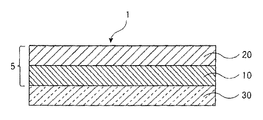
- FIG. 1 is a cross-sectional view showing an example of the configuration of the laminate of the present invention.
- FIG. 2 is a cross-sectional view showing an example of the configuration of the laminate of the present invention.
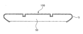
- FIG. 3 is a cross-sectional view illustrating the configuration of the decorative molded body of the present invention.
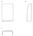
- FIG. 4 is a diagram for explaining a molded body used in Examples and Comparative Examples. 4A is a top view, FIG. 4B is a right side view, and FIG. 4C is a bottom view.
- a numerical range represented by using “ ⁇ ” means a range including numerical values described before and after “ ⁇ ” as a lower limit value and an upper limit value.
- the laminate of the present invention has a pressure-sensitive adhesive layer, a surface layer laminated on one surface side of the pressure-sensitive adhesive layer, and the other surface side of the pressure-sensitive adhesive layer opposite to the surface on which the surface layer is laminated. And a resin separator layer laminated on the surface side.
- at least one of the pressure-sensitive adhesive layer, the surface layer, and the separator layer has a layer having a surface electrical resistance of 1 ⁇ 10 5 to 1 ⁇ 10 12 ⁇ / ⁇ .
- a layer having a surface electrical resistance of 1 ⁇ 10 5 to 1 ⁇ 10 12 ⁇ / ⁇ means that the surface electrical resistance of any one surface of the layer is within the above range. Is shown.
- the layer constituting each layer of the pressure-sensitive adhesive layer, the surface layer or the separator layer may have a surface electric resistance within the above range, and each layer of the pressure-sensitive adhesive layer, the surface layer or the separator layer itself is within the above range. It may have an inner surface electrical resistance. Especially, it is preferable that at least one surface selected from both surfaces of the adhesive film comprised from an adhesive layer and a surface layer, and both surfaces of a separator layer has the surface electrical resistance in the said range. In addition, any one of the pressure-sensitive adhesive layer, the surface layer, and the separator layer may have a surface electrical resistance within the above range, and two or more layers of the above layer have a surface electrical resistance within the above range. You may do it. For example, the pressure-sensitive adhesive layer and the separator layer may have a surface electrical resistance within the above range.
- the laminate of the present invention has the above-described configuration, it is possible to suppress biting of foreign matters during molding under vacuum conditions or reduced pressure conditions (during TOM molding). Moreover, since the separator layer which comprises the laminated body of this invention is a resin layer, when peeling a separator layer from a laminated body, it can suppress that the foreign material derived from a separator layer adheres to an adhesive layer. . For this reason, it becomes possible to suppress biting of a foreign substance more effectively.
- the surface electrical resistance of each layer is a value measured by Hiresta UX MCP-HT800 (manufactured by Mitsubishi Chemical Analytech Co., Ltd., measurement method: constant voltage application / leakage current measurement method).
- FIG. 1 is a cross-sectional view showing an example of the configuration of the laminate of the present invention.
- the laminate 1 of the present invention includes an adhesive layer 10, a surface layer 20 laminated on one surface side of the adhesive layer 10, and the other surface of the adhesive layer 10.
- the separator layer 30 is laminated on the side opposite to the surface on which the surface layer 20 is laminated. Since the laminate 1 has the separator layer 30, foreign matters such as dust are suppressed from adhering to the surface of the pressure-sensitive adhesive layer 10 when the laminate 1 is stored. When using the laminated body 1 of this invention, this separator layer 30 is peeled and the adhesive layer 10 is exposed. And the adhesive layer 10 will be stuck by the molded object which is a to-be-adhered body. In this specification, the laminated body from which the separator layer 30 has been peeled is referred to as an adhesive film 5.
- FIG. 2 is a cross-sectional view showing a preferred configuration of the laminate of the present invention.
- the surface layer 20 is preferably a layer including a surface protective layer 22 and a colored layer 24.
- the separator layer 30 is preferably a layer including a base material layer 32, a release agent layer 34, and an antistatic layer 36.
- the laminate 1 of the present invention may have a layer other than the layers described above, the surface layer 20 may further have an antistatic layer, and the pressure-sensitive adhesive layer may be a colored layer or an antistatic layer. The structure which has may be sufficient.
- the pressure-sensitive adhesive film 5 is obtained.
- the present invention also relates to such an adhesive film.
- the laminate of the present invention since the laminate of the present invention has the above-described configuration, it may be in the form of a sheet or may be wound up into a roll. When it is wound up in a roll shape, it is preferable to wind up so that the separator layer is disposed on the core shaft side.
- the laminate of the present invention includes a separator layer.
- the separator layer is made of resin and does not include a paper base material. By using such a separator layer, foreign matters such as paper-derived dust are not caught between the laminate and the molded body, and the biting of foreign matters can be effectively suppressed.
- the surface electrical resistance of the separator layer is preferably 1 ⁇ 10 5 to 1 ⁇ 10 12 ⁇ / ⁇ , and more preferably 1 ⁇ 10 6 to 1 ⁇ 10 12 ⁇ / ⁇ .
- a foreign material In a laminated body, there exists a tendency for a foreign material to adhere to an adhesive layer easily by the electrostatic interaction at the time of peeling a separator layer.
- this invention by setting the surface electrical resistance of the separator layer within the above range, it is possible to suppress the adhesion of foreign matters, and in particular, foreign matters during molding under vacuum conditions or reduced pressure conditions (during TOM molding). Can be more effectively suppressed.
- this invention relates also to the separator laminated
- the separator layer has a single layer configuration, and the surface electric resistance of the single layer may be within the above range, but it is preferable that the surface electric resistance has a layer within the above range.
- the separator layer is a base material layer, a release agent layer laminated on one side of the base material layer, and the other surface side of the base material layer, and the release agent layer is laminated. It is preferable to have an antistatic layer laminated on the surface opposite to the surface.
- the surface electrical resistance of the antistatic layer is preferably 1 ⁇ 10 5 to 1 ⁇ 10 12 ⁇ / ⁇ .
- the separator layer preferably contains an antistatic agent
- the pressure-sensitive adhesive film composed of the surface layer and the pressure-sensitive adhesive layer preferably contains no antistatic agent.
- a separator layer peels from a laminated body and becomes an adhesive film comprised from a surface layer and an adhesive layer. And this adhesive film is affixed on the molded object which is a to-be-adhered body. That is, when only the separator layer contains the antistatic agent, the decorative molded body does not contain the antistatic agent, and the durability of the whole decorative molded body is further improved.
- the separator layer 30 is preferably a layer including a base material layer 32, a release agent layer 34, and an antistatic layer 36.
- the antistatic layer 36 is an antistatic agent. It is preferable to contain.
- the antistatic agent is preferably at least one selected from ionic antistatic agents, organic antistatic agents, and inorganic antistatic agents, and is selected from organic antistatic agents and inorganic antistatic agents. At least one kind is more preferable, and an inorganic antistatic agent is particularly preferable.
- the organic antistatic agent is more preferably a ⁇ -conjugated conductive polymer antistatic agent.
- the humidity dependence of the antistatic performance can be suppressed. That is, the antistatic performance can be exhibited in any humidity range.
- the inorganic antistatic agent can exhibit excellent antistatic performance even in a low humidity environment.
- an ionic antistatic agent is comparatively cheap, the manufacturing cost of a laminated body can be suppressed.
- any known ionic antistatic agent can be used in the present invention.
- glyceric acid fatty acid ester, polyglycerin fatty acid ester, sorbitan fatty acid ester, polyoxyethylene sorbitan fatty acid ester, polyoxyethylene is used.
- ⁇ -conjugated conductive polymer antistatic agent is preferably used as the organic antistatic agent.
- any known ⁇ -conjugated conductive polymer antistatic agent can be used in the present invention.
- polythiophene, polypyrrole, polyaniline, etc. are used. Particularly preferred is polythiophene.
- any known inorganic antistatic agent can be used in the present invention, and preferably an ATO (antimony-doped tin oxide) filler, an ITO (tin-doped indium oxide) filler, a silver nanofiller, or antimony oxide.
- ATO antimony-doped tin oxide
- ITO tin-doped indium oxide
- silver nanofiller tin-doped indium oxide
- antimony oxide examples thereof include doped tin oxide-coated titanium oxide, and silver nanofillers are particularly preferable.
- the content of the antistatic agent is preferably 2 to 100% by mass and more preferably 50 to 100% by mass with respect to the total mass of the antistatic layer.
- the coating amount of the antistatic agent layer after drying is preferably 0.001 to 1 g / m 2 , and particularly preferably 0.01 to 0.2 g / m 2 .
- the base material layer constituting the separator layer is preferably a resin layer, and the resin layer is preferably composed of a thermoplastic resin.
- the base material layer include a polyolefin film, a polyvinyl chloride film, a polyvinyl alcohol film, a polyester film, a polycarbonate film, a polystyrene film, and a polyacrylonitrile film.
- a polyester film is preferably used, and a polyethylene terephthalate (PET) film is particularly preferably used.
- PET polyethylene terephthalate
- the release agent layer contains a release agent.
- a general-purpose addition type or condensation type silicone release agent is used.
- an addition type silicone release agent having high reactivity is preferably used.
- Specific examples of silicone release agents include BY24-162 and SD-7234 manufactured by Toray Dow Corning Silicone, and KS-3600, KS-774, and X62-2600 manufactured by Shin-Etsu Chemical Co., Ltd. Is mentioned.
- the silicone release agent contains a silicone resin that is an organosilicon compound having a SiO 2 unit and a (CH 3 ) 3 SiO 1/2 unit or a CH 2 ⁇ CH (CH 3 ) SiO 1/2 unit. It is preferable to do.
- Specific examples of the silicone resin include BY24-843, SD-7292, SHR-1404 and the like manufactured by Toray Dow Corning Silicone, and KS-3800 and X92-183 manufactured by Shin-Etsu Chemical Co., Ltd.
- Auxiliary additives such as a catalyst and an adhesion improver can be added to the release agent layer.
- Preferred examples of the catalyst include platinum-based and tin-based catalysts. Any adhesion improver can be used as long as adhesion is improved, and a silane coupling agent can be preferably used.
- the coating amount of the release agent layer after drying is preferably 0.01 to 1 g / m 2 and particularly preferably 0.05 to 0.2 g / m 2 .
- the separator layer can be formed by applying a release agent-containing liquid and an antistatic agent-containing liquid to the base material layer and drying.
- a size press coater, gate roll coater, bar coater, roll coater, air knife coater, blade coater, rod blade coater, curtain coater, gravure coater or the like can be used.
- it is preferable to use a two-head coater that can be applied at one time on the front and back, and a two-head coater that can be coated on the front and back with a gravure head that can control a small amount of coating is particularly preferable.
- a functional layer can be simultaneously formed on both surfaces of a base material layer, and the production efficiency of a separator layer can be improved.
- the laminate of the present invention includes an adhesive layer.
- a molded object can be decorated by an adhesive layer sticking on the surface of a molded object.
- the surface electrical resistance of the pressure-sensitive adhesive layer is preferably 1 ⁇ 10 5 to 1 ⁇ 10 12 ⁇ / ⁇ , and more preferably 1 ⁇ 10 6 to 1 ⁇ 10 12 ⁇ / ⁇ .
- the pressure-sensitive adhesive layer contains a polymer as a pressure-sensitive adhesive.
- the pressure-sensitive adhesive layer preferably contains an antistatic agent.
- the pressure-sensitive adhesive layer preferably contains an antistatic agent.
- the antistatic agent contained in the pressure-sensitive adhesive layer the same antistatic agents as can be contained in the separator layer can be listed, and the preferred antistatic agents are also the same.
- the content of the antistatic agent is preferably 0.1 to 10% by weight, and preferably 0.5 to 7% by weight, based on the total weight of the pressure-sensitive adhesive layer. More preferably, the content is 1 to 5% by mass.
- the thickness of the pressure-sensitive adhesive layer is preferably 5 to 500 ⁇ m, more preferably 10 to 350 ⁇ m, and further preferably 20 to 200 ⁇ m.
- the average molecular weight of the polymer constituting the pressure-sensitive adhesive layer is preferably 10,000 to 5,000,000, and more preferably 300,000 to 2,000,000. By making the average molecular weight of the polymer within the above range, it is possible to improve the followability to the molded product during molding under vacuum or reduced pressure conditions (TOM molding), and decorate molded products with complex shapes. can do. Further, the molecular weight distribution (Mw / Mn) of the polymer is preferably from 2 to 30, and particularly preferably from 4 to 20. In order to obtain the target molecular weight distribution, two or more kinds of polymers having different average molecular weights can be mixed and used. By broadening the molecular weight distribution of the polymer, it is possible to improve the followability to the molded product during molding under vacuum or reduced pressure conditions (TOM molding), and to decorate a molded product with a complicated shape. it can.
- the adhesive strength measured based on JIS Z 0237 is preferably 10 to 100 N / 25 mm, and more preferably 25 to 75 N / 25 mm.
- the polymer constituting the pressure-sensitive adhesive layer preferably contains at least one acrylic polymer.
- acrylic polymers aliphatic (C5) petroleum resins, aromatic (C9) petroleum resins, copolymerized (C5 / C9) petroleum resins, dicyclopentadiene (DCPD) petroleum resins, coumarone indene resins, A styrene resin including ⁇ -methylstyrene resin, rosin, rosin ester resin, terpene resin, aromatic modified terpene resin, terpene phenol resin, and hydrogenated resins thereof may be contained.
- Examples of the monomer unit constituting the acrylic polymer include alkyl (meth) acrylate, urethane (meth) acrylate, epoxy (meth) acrylate, polyester (meth) acrylate, polyether (meth) acrylate, and methyl methacrylate. , N-butyl methacrylate and iso-butyl methacrylate can be preferably mentioned.
- a component having a carboxyl group preferably acrylic acid, methacrylic acid, maleic acid, crotonic acid, crotonic acid, ⁇ -carboxyethyl acrylate, and / or a component having a hydroxyl group, preferably 2-hydroxyethyl (meth) Acrylate, humanroxypropyl (meth) acrylate, 2-hydroxybutyl (meth) acrylate, chloro-2-hydroxyethyl (meth) acrylate, 4-hydroxybutyl (meth) acrylate, 6-hydroxyhexyl (meth) acrylate, 8-hydro Examples thereof include octyl (meth) acrylate and / or copolymerizable unsaturated component, preferably acrylamide, methacrylamide, vinyl acetate, (meth) acrylonitrile, and macromer.
- carboxyl group-containing component preferably acrylic acid, methacrylic acid, maleic acid, crotonic acid, crotonic acid,
- additives such as fillers, pigments, thickeners, viscosity modifiers, wetting agents, leveling agents, antifoaming agents, preservatives, dispersing agents, antioxidants, freezing
- additives such as fillers, pigments, thickeners, viscosity modifiers, wetting agents, leveling agents, antifoaming agents, preservatives, dispersing agents, antioxidants, freezing
- You may contain an inhibitor, a flame retardant, etc. in the range which does not impair the effect of this invention.
- the laminate of the present invention includes a surface layer.
- the surface layer may have a single layer structure, but is preferably a layer having a surface protective layer containing an ultraviolet absorber and a colored layer.
- the colored layer preferably contains pigments, dyes, metals, metal oxides, and the like.
- the colored layer may be a resin layer containing a pigment, dye, metal, or metal oxide, or may be a vapor deposition or sputter layer made of a pigment, dye, metal, or metal oxide, or a pigment, dye, metal, or metal.
- An ink layer containing an oxide may be printed on the surface layer. In this case, the printed part may be called a colored layer (colored part).
- the printing method in this case is not particularly limited, and examples thereof include letterpress printing, offset printing, flexographic printing, gravure printing, and ink jet printing.
- Examples of the printing ink used for these printing include oxidation polymerization type oil-based ink, soybean oil ink, vegetable oil ink, and UV curable UV ink, LED-UV ink, gravure ink, flexographic ink, screen ink, and the like.
- gravure ink, screen ink, and inkjet ink are preferable.
- Additives such as pigment dispersants, antifoaming agents, ultraviolet absorbers, antioxidants, antistatic agents, antiwear agents, and antiblocking agents may be added to the printing ink as necessary. .
- the resin layer is preferably composed of a thermoplastic resin.
- ABS resin acrylonitrile, butadiene and styrene copolymer
- AS resin acrylonitrile and styrene copolymer
- acrylic resin polyethylene terephthalate, polybutylene terephthalate, nylon, polyacetal, polyphenylene oxide, Phenol resin, urea resin, melamine resin, liquid crystal polymer, polytetrafluoroethylene, polyvinylidene fluoride, polysulfone, polyethersulfone, polyacetal, polyetheretherketone, polyphenylene sulfide, polyetherimide, polyamideimide, polycarbonate, polyethylene, polypropylene, polystyrene A urethane resin or the like is preferable.
- the pigments that the colored layer may have include inorganic pigments (alumina white, titanium oxide, zinc white, black iron oxide, mica-like iron oxide, lead white, white carbon, molybdenum white, carbon black, resurge, lithopone, barite.
- inorganic pigments alumina white, titanium oxide, zinc white, black iron oxide, mica-like iron oxide, lead white, white carbon, molybdenum white, carbon black, resurge, lithopone, barite.
- Insoluble azo pigments soluble azo pigments such as lithol red, helio bordeaux, pigment scarlet, permanent red 2B, derivatives such as alizarin, indanthrone, thioindigo maroon, phthalocyanine pigments such as phthalocyanine blue, phthalocyanine green, quinacridone red, quinacridone Quinacridone pigments such as magenta, perylene pigments such as perylene red and perylene scarlet, isoindolinone pigments such as isoindolinone yellow and isoindolinone orange, benzimidazolone yellow, benzimidazolone orange, and benzimidazolone red Imidazolone pigments, pyranthrone pigments such as pyranthrone red, pyranthrone orange, thioindigo pigments, condensed azo pigments, diketopiro Pyrrole pigments, Flavanthrone Yellow, Acylamide Yellow, Quinophthalone Yellow
- the dye that the colored layer may have include an acid dye, a basic dye, a direct dye, a reactive dye, a disperse dye, and a food coloring.
- any known dye can be used and is not limited.
- these dyes azo dyes and phthalocyanine dyes are particularly preferable, and acid dyes, direct dyes, reactive dyes, food dyes, and the like are particularly preferable.
- Examples of the metal layer that the colored layer may have include aluminum, gold, silver, nickel, and indium.
- the surface protective layer is a layer constituting the outermost surface of the laminate, and is also a layer constituting the outermost surface in the decorative molded body.
- the surface protective layer is required to have resistance to scratching, strength, and the like.
- the surface protective layer in the present invention preferably has a pencil hardness of B or higher, more preferably F or higher.
- the surface protective layer is preferably a resin layer.
- ABS resin acrylonitrile, butadiene and styrene copolymer
- AS resin acrylonitrile and styrene copolymer
- acrylic resin polyethylene terephthalate, polybutylene terephthalate, nylon, polyacetal, polyphenylene oxide, Phenol resin, urea resin, melamine resin, liquid crystal polymer, polytetrafluoroethylene, polyvinylidene fluoride, polysulfone, polyethersulfone, polyacetal, polyetheretherketone, polyphenylene sulfide, polyetherimide, polyamideimide, polycarbonate, polyethylene, polypropylene, polystyrene Preferred examples include urethane resin and the like.
- the surface protective layer of the present invention may be an ionizing radiation curable resin.
- the ionizing radiation curable resin is a resin that is cured by irradiation with an electron beam or ultraviolet rays.
- the ionizing radiation curable resin is preferably substantially transparent.
- an acrylic ultraviolet curable resin is preferably used as the substantially transparent ionizing radiation curable resin.
- an antistatic agent may be contained between the surface protective layer and / or the colored layer.
- the antistatic agent the same antistatic agent as mentioned in the item of the separator layer can be used.
- the laminate of the present invention is preferably used for molding under vacuum conditions or reduced pressure conditions.
- the laminate of the present invention it is possible to prevent foreign matter such as dust from being caught between the pressure-sensitive adhesive layer and the molded body in molding under vacuum conditions or reduced pressure conditions.
- the laminated body of this invention can exhibit the effect by being used for shaping
- molding under vacuum conditions or reduced pressure conditions is so-called TOM molding.
- TOM molding method a process of laminating an adhesive film (laminated film of a surface layer and an adhesive layer) on a molded body under vacuum conditions or reduced pressure conditions, and a process of pressure-bonding the adhesive film to the molded body by a pressure difference Including.
- molding under a vacuum condition or a reduced pressure condition does not include a method of bringing the pressure-sensitive adhesive film and the molded body into close contact with each other using a vacuum body provided with vacuum holes.
- the molding under a vacuum condition or a reduced pressure condition can be performed by using a “vacuum molding apparatus” described in Japanese Patent No. 3733564.
- the present invention also relates to a method for producing a decorative molded body as described above.
- the method for producing a decorative molded body of the present invention includes a step of peeling the separator layer from the above-described laminate to obtain an adhesive film having a surface layer and an adhesive layer, and under vacuum or reduced pressure conditions. And a step of bringing the pressure-sensitive adhesive film and the molded body into close contact with each other and a step of pressure-bonding the pressure-sensitive adhesive film and the molded body under pressured air conditions.
- the method for producing a decorative molded body preferably includes a step of heating the surface of the laminate to 100 to 180 ° C. after the step of closely attaching the adhesive film and the molded body. In this case, an infrared heater is preferably used for heating the surface of the laminate.
- the present invention also relates to a decorative molded body including an adhesive film composed of the surface layer and the adhesive layer of the laminate as described above, and a molded body decorated with the adhesive film.
- the decorative molded body is obtained by attaching an adhesive film to a part or the entire surface of the molded body. That is, in the decorative molded body, the surface layer is laminated via the pressure-sensitive adhesive layer.
- FIG. 3 is a cross-sectional view illustrating the configuration of the decorative molded body 100.
- FIG. 3 shows a state in which a molded body 50 having a concave portion on the surface is decorated with an adhesive film 5.
- the reverse taper portion and the end winding portion can be covered and molded without providing the molded body 50 with vacuum holes.
- it can decorate regardless of the material of a product. Thereby, it can decorate also about the molded object surface which has a complicated three-dimensional unevenness
- the molded body 50 examples include metal materials such as ED steel plates, Mg alloys, SUS, and aluminum alloys, and resin molded bodies, but resin molded bodies are preferable.
- ABS resin acrylonitrile-butadiene-styrene copolymer
- polycarbonate-containing resin examples include polycarbonate-containing resin, polybutylene terephthalate, a resin blended with polycarbonate or ABS resin (PCABS), or the like.
- PCABS polypropylene
- PP polypropylene
- the shape of the molded body 50 may be flat or substantially flat, or may be non-planar.
- the shape of the molded body 50 may be a shape having a concave portion on the surface as shown in FIG. 3, or a shape having a convex portion on the surface (not shown). Good.
- the molded body 50 may have a shape having a reverse taper portion or a terminal winding portion. According to the present invention, even if it is a non-planar shaped product which is likely to have a defect in appearance, it is possible to suppress the biting of foreign matter and prevent problems such as peeling.
- the decorative molded body obtained by the present invention includes, for example, automotive parts (for example, parts such as bodies, bumpers, spoilers, mirrors, wheels, interior materials, etc., and various materials), motorcycle parts, and roads. Used for materials (for example, traffic signs, noise barriers, etc.), tunnel materials (for example, side walls), railway vehicles, furniture, musical instruments, household appliances, building materials, containers, office supplies, sports equipment, toys, etc. it can.
- automotive parts for example, parts such as bodies, bumpers, spoilers, mirrors, wheels, interior materials, etc., and various materials
- materials for example, traffic signs, noise barriers, etc.
- tunnel materials for example, side walls
- railway vehicles for example, furniture, musical instruments, household appliances, building materials, containers, office supplies, sports equipment, toys, etc. it can.
- Example 1 In a clean room (class 1000), the acrylic pressure-sensitive adhesive A was applied on the separate film A so that the thickness after drying was 25 ⁇ m. It dried for 3 minutes at 90 degreeC, and obtained the separator layer with an adhesive layer. Using the hard coat film A as the surface protective layer (surface layer), the pressure-sensitive adhesive layer surface of the obtained separator layer with the pressure-sensitive adhesive layer and the hard coat film A were bonded in a clean room (class 1000). Aging was performed for 7 days in an environment of 50 ° C. and 50% relative humidity. In this way, a laminate 1 was obtained.
- the separator layer was removed from the laminate 1 to obtain an adhesive film 1.
- the adhesive film 1 was set on a TOM molding machine.
- a rainproof line-cover (ABS resin, manufactured by Panasonic Corporation, product number: WP9171) is placed on a TOM molding machine (cloth vacuum) so that the outer surface (convex surface) side of the cover and the adhesive layer of the adhesive film 1 face each other. (Manufactured by NGF molding machine).
- the decorative molded body 1 was obtained by laminating the adhesive film 1 on the molded body at 130 ° C. using a TOM molding machine. Ten decorative molded bodies 1 were produced in the same manner.
- the shape of the rainproof line cover is shown in FIGS.
- the rainproof cover shown in FIGS. 4 (a) to 4 (c) has a length (longitudinal) direction of 90 mm when viewed from above as shown in FIG.
- the length in the (lateral) direction was 60 mm.
- ⁇ Separate film A> On one side of 50 ⁇ m thick PET (Toray Industries, Lumirror T60), apply glycerin monostearate in a clean room (class 1000) so that the coating amount after drying is 0.1 g / m 2. The treatment was performed at 130 ° C. for 30 seconds in a dryer. In this way, an antistatic layer was formed. Next, on the opposite surface, a release agent comprising 100 parts by mass of thermosetting silicone (manufactured by Toray Dow Corning, LTC300B) and 1 part by mass of catalyst (manufactured by Toray Dow Corning, SRX212) is dried.
- thermosetting silicone manufactured by Toray Dow Corning, LTC300B
- catalyst manufactured by Toray Dow Corning, SRX212
- the release agent layer A was formed by performing a treatment at 130 ° C. for 60 seconds in a dryer.
- a separate film A (separator layer A) was obtained as described above.
- the release agent layer side was 5 ⁇ 10 16 ⁇ / ⁇
- the antistatic layer side was 7 ⁇ 10 11 ⁇ / ⁇ . It was.
- the glass transition temperature (Tg) of the polymer A was measured with the differential operation type
- the pressure-sensitive adhesive A was obtained by blending such that the ratio was 98: 10: 2.
- the molecular weight distribution of the pressure-sensitive adhesive A was 6.5.
- the molecular weight and molecular weight distribution were measured by GPC.
- the surface electrical resistance of the pressure-sensitive adhesive layer formed by applying the pressure-sensitive adhesive A under the conditions of 23 ° C. and 50% relative humidity was measured, it was 2 ⁇ 10 15 ⁇ / ⁇ .
- a hard coat film A was used as the surface protective layer.
- As the hard coat film A acryloprene HBA001P manufactured by Mitsubishi Rayon Co., Ltd. was used. This film had a pencil hardness of 2H and a thickness of 125 ⁇ m.
- the surface electrical resistance in an environment of 23 ° C. and 50% relative humidity was 2 ⁇ 10 16 ⁇ / ⁇ on both sides.
- Example 2 A decorative molded body 2 was obtained in the same manner as in Example 1 except that the adhesive B was used instead of the adhesive A. The results are shown in Table 1.
- Mw molecular weight
- Tg Tg
- the obtained polymer B1, polymer B2, a crosslinking agent (manufactured by Mitsubishi Gas Chemical Co., Ltd., Tetrad X), and bistrifluoromethanesulfonimide were blended so that the dry weight ratio was 46: 40: 2: 2.
- an adhesive B was obtained.
- the molecular weight distribution of the adhesive B was 18.
- the surface electrical resistance of the pressure-sensitive adhesive layer formed by applying the pressure-sensitive adhesive B under the conditions of 23 ° C. and 50% relative humidity was measured, it was 7 ⁇ 10 10 ⁇ / ⁇ .
- Example 3 A decorative molded body 3 was obtained in the same manner as in Example 2 except that the separate film B was used instead of the separate film A. The results are shown in Table 1.
- ⁇ Separate film B> On one side of 38 ⁇ m thick PET (Toray Industries, Lumirror T60), 100 parts by mass of thermosetting silicone (Toray Dow Corning, LTC300B), 1 part by mass of catalyst (Toray Dow Corning, SRX212) The release agent consisting of was applied at a weight after drying of 0.1 g / m 2 . The treatment was performed at 130 ° C. for 60 seconds with a dryer to form release agent layer B. A separate film B (separator layer B) was obtained as described above. When the surface electrical resistance was measured at 23 ° C. and a relative humidity of 50%, the release agent layer side was 5 ⁇ 10 16 ⁇ / ⁇ , and the non-release agent layer side was 5 ⁇ 10 16 ⁇ / ⁇ .
- Example 4 instead of the hard coat film A, PET-B (organic antistatic agent kneaded grade PET film) having a thickness of 100 ⁇ m (Lumirror X53, manufactured by Toray Industries, Inc.) was used. The surface electrical resistance of PET-B under conditions of 23 ° C. and 50% relative humidity was 1 ⁇ 10 10 ⁇ / ⁇ . Further, a separate film B was used in place of the separate film A. A decorative molded body 4 was obtained in the same manner as in Example 1 except for the above.
- PET-B organic antistatic agent kneaded grade PET film having a thickness of 100 ⁇ m (Lumirror X53, manufactured by Toray Industries, Inc.) was used. The surface electrical resistance of PET-B under conditions of 23 ° C. and 50% relative humidity was 1 ⁇ 10 10 ⁇ / ⁇ .
- a separate film B was used in place of the separate film A.
- a decorative molded body 4 was obtained in the same manner as in Example 1 except for the above.
- Example 5 A decorative molded body 5 was obtained in the same manner as in Example 1 except that the separate film C was used instead of the separate film A, and the adhesive C was used instead of the adhesive A. The results are shown in Table 1.
- a release agent comprising 100 parts by mass of thermosetting silicone (manufactured by Toray Dow Corning, LTC300B) and 1 part by mass of catalyst (manufactured by Toray Dow Corning, SRX212) is weight after drying. It was applied in a clean room (class 1000) so as to be 0.1 g / m 2 .
- the release agent layer C was formed by performing a treatment at 130 ° C. for 60 seconds with a dryer. A separate film C (separator layer C) was obtained as described above. When the surface electrical resistance was measured under the conditions of 23 ° C. and 50% relative humidity, it was 5 ⁇ 10 16 ⁇ / ⁇ on the release agent layer side and 3 ⁇ 10 9 ⁇ / ⁇ on the antistatic layer side.
- Example 6 On the entire back surface of the hard coat film A, an ink (OS-M [NL] Indigo, manufactured by Dainichi Seika) was applied with a gravure printing machine so that the thickness after drying was 5 ⁇ m, and a colored layer ( A surface layer provided with an ink layer) was prepared. A decorative molded body 6 was obtained in the same manner as in Example 1 except that such a surface layer was used. The results are shown in Table 1.
- OS-M [NL] Indigo manufactured by Dainichi Seika
- Example 7 A decorative molded body 7 was obtained in the same manner as in Example 6 except that the separate film C was used instead of the separate film A. The results are shown in Table 1.
- Example 8 A decorative molded body 8 was obtained in the same manner as in Example 6 except that the separate film D was used instead of the separate film A. The results are shown in Table 1.
- a release agent comprising 100 parts by mass of thermosetting silicone (manufactured by Toray Dow Corning, LTC300B) and 1 part by mass of catalyst (manufactured by Toray Dow Corning, SRX212) is dried. It was applied in a clean room (class 1000) so as to have a weight of 0.1 g / m 2 .
- a release agent layer D was formed by performing a treatment at 130 ° C. for 60 seconds in a dryer.
- a separate film D (separator layer D) was obtained as described above.
- the release agent layer side was 5 ⁇ 10 16 ⁇ / ⁇
- the antistatic layer side was 6 ⁇ 10 6 ⁇ / ⁇ .
- Example 9 instead of the hard coat film A, a surface layer obtained by applying indium vapor deposition (thickness: 30 nm) on the back surface of easy-formed PET (Soft Shine TA009, manufactured by Toyobo Co., Ltd.) is used. A decorative molded body 9 was obtained in the same manner as in Example 1 except that it was used. The results are shown in Table 1.
- Example 1 A decorative molded body 11 was obtained in the same manner as in Example 1 except that the separate film B was used instead of the separate film A. The results are shown in Table 1.
- Example 3 A decorative molded body 13 was obtained in the same manner as in Example 1 except that the film C was used instead of the hard coat film A. The results are shown in Table 1.
- Comparative Example 4 A decorative molded body 14 was obtained in the same manner as in Comparative Example 3 except that the adhesive C was used instead of the adhesive A. The results are shown in Table 1.
- Example 5 A decorative molded body 15 was obtained in the same manner as in Example 1, except that separate paper E (manufactured by Oji Tac Co., Ltd., single-sided polyethylene laminated paper separator (trade name: L6W)) was used instead of the separate film A. The results are shown in Table 1.
- the decorative molded body obtained in the example it can be seen that the number of defects is reduced. In particular, it is found that durability is excellent in the case where the laminate is used within the predetermined range of the surface electrical resistance value of the separator layer.
- SYMBOLS 1 Laminated body, 5 ... Adhesive film, 10 ... Adhesive layer, 20 ... Surface layer, 22 ... Surface protective layer, 24 ... Colored layer, 30 ... Separator layer, 32 ... Base material layer, 34 ... Release agent layer, 36 ... Antistatic layer, 50 ... molded body, 100 ... decorated molded body
Landscapes
- Chemical & Material Sciences (AREA)
- Organic Chemistry (AREA)
- Inorganic Chemistry (AREA)
- Physics & Mathematics (AREA)
- Fluid Mechanics (AREA)
- Laminated Bodies (AREA)
- Adhesive Tapes (AREA)
- Adhesives Or Adhesive Processes (AREA)
Abstract
Description
本願は、2015年1月27日に出願された日本国特願2015−013331号に基づく優先権を主張し、その内容をここに援用する。
具体的に、本発明は、以下の構成を有する。
[2]セパレーター層は、表面電気抵抗が1×10⁵~1×10¹²Ω/□である層を有する[1]に記載の積層体。
[3]セパレーター層は、基材層と、基材層の一方の面側に積層された剥離剤層と、基材層の他方の面側であって、剥離剤層が積層された面とは反対の面側に積層された帯電防止層とを有し、帯電防止層の表面電気抵抗が1×10⁵~1×10¹²Ω/□である[1]又は[2]に記載の積層体。
[4]帯電防止層は、無機系帯電防止剤を含む[3]に記載の積層体。
[5]粘着剤層の表面電気抵抗が1×10⁵~1×10¹²Ω/□である[1]~[4]のいずれかに記載の積層体。
[6]粘着剤層は、無機系帯電防止剤を含む[5]に記載の積層体。
[7]表面層は、紫外線吸収剤を含有する表面保護層と、有色層とを有する[1]~[6]のいずれかに記載の積層体。
[8]真空条件下又は減圧条件下での成形に用いられる[1]~[7]のいずれかに記載の積層体。
[9][1]~[8]のいずれかに記載の積層体の表面層及び粘着剤層から構成される粘着フィルムと、粘着フィルムで加飾された成形体とを含む加飾成形体。
[10]前記成形体が非平面形状である[9]に記載の加飾成形体。
[11]積層体を用いて加飾成形体を製造する方法であって、積層体は、粘着剤層と、粘着剤層の一方の面側に積層された表面層と、粘着剤層の他方の面側であって、表面層が積層された面とは反対の面側に積層された樹脂製のセパレーター層とを有し、粘着剤層、表面層、及びセパレーター層の少なくともいずれかは、表面電気抵抗が1×10⁵~1×10¹²Ω/□である層を有し、積層体からセパレーター層を剥離して、表面層及び粘着剤層を有する粘着フィルムを得る工程と、真空条件下又は減圧条件下において、粘着フィルムを成形体に積層する工程と、気圧差により、粘着フィルムを成形体に圧着する工程とを含むことを特徴とする加飾成形体の製造方法。
[12]基材層と、基材層の一方の面側に積層され、表面電気抵抗が1×10⁵~1×10¹²Ω/□である樹脂層と、基材層の他方の面側に積層された剥離剤層とを有する樹脂製のセパレーターであって、真空条件下又は減圧条件下での成形に用いられる粘着フィルムを保護するために用いられるセパレーター。
[13]粘着剤層と、粘着剤層の一方の面側に積層された表面層とを有し、粘着剤層及び表面層の少なくともいずれかは、表面電気抵抗が1×10⁵~1×10¹²Ω/□である層を有することを特徴とする粘着フィルム。
本発明の積層体は、粘着剤層と、粘着剤層の一方の面側に積層された表面層と、粘着剤層の他方の面側であって、表面層が積層された面とは反対の面側に積層された樹脂製のセパレーター層とを有する。また、粘着剤層、表面層、及びセパレーター層の少なくともいずれかは、表面電気抵抗が1×10⁵~1×10¹²Ω/□である層を有する。なお、本明細書において、表面電気抵抗が1×105~1×1012Ω/□である層とは、該層のいずれか一方の面の表面電気抵抗が上記範囲内であればよいことを示している。
また、粘着剤層、表面層又はセパレーター層のいずれか1層が上記範囲内の表面電気抵抗を有していればよく、上記層の2層以上の層が上記範囲内の表面電気抵抗を有していてもよい。例えば、粘着剤層及びセパレーター層が上記範囲内の表面電気抵抗を有していてもよい。
なお、図2に示されたような積層体1においてもセパレーター層30が剥離された後は、粘着フィルム5となる。本発明はこのような粘着フィルムに関するものでもある。
本発明の積層体は、セパレーター層を含む。セパレーター層は、樹脂製であり、紙基材を含まない層である。このようなセパレーター層を用いることにより、紙由来のゴミ等の異物が、積層体と成形体との間に挟まることがなくなり、異物の噛み込みを効果的に抑制することができる。
剥離剤層の乾燥後の塗布量は、0.01~1g/m2であることが好ましく、0.05~0.2g/m2であることが特に好ましい。
本発明の積層体は、粘着剤層を含む。本発明では、粘着剤層が成形体の表面に貼着することで、成形体を加飾することができる。なお、粘着剤層の表面電気抵抗は1×10⁵~1×10¹²Ω/□であることが好ましく、1×106~1×1012Ω/□であることがより好ましい。
ポリマーの分子量分布を広くすることにより、真空条件下又は減圧条件下での成形(TOM成形)時に、成形体への追従性を高めることができ、複雑な形状の成形体も加飾することができる。
アクリル系ポリマーを構成する単量体単位としては、アルキル(メタ)アクリレート、ウレタン(メタ)アクリレート、エポキシ(メタ)アクリレート、ポリエステル(メタ)アクリレート、ポリエーテル(メタ)アクリレート等が挙げられ、メチルメタクリレート、n−ブチルメタクリレート、iso−ブチルメタクリレートを好ましく挙げることができる。
本発明の積層体は、表面層を含む。表面層は単層構成であってもよいが、紫外線吸収剤を含有する表面保護層と、有色層とを有する層であることが好ましい。なお、有色層とは、顔料、染料、金属、金属酸化物等を含有することが好ましい。有色層は、顔料、染料、金属、金属酸化物を含有する樹脂層であってもよく、顔料、染料、金属、金属酸化物からなる蒸着、スパッタ層でもよく、また顔料、染料、金属、金属酸化物を含むインキ層を表面層に印刷で施したものであってもよい。この場合は、その印刷部のことを有色層(有色部)と呼んでもよい。この場合の、印刷方法としては特に制限されず、例えば、凸版印刷、オフセット印刷、フレキソ印刷、グラビア印刷、インクジェット印刷などが挙げられる。これらの印刷に用いる印刷インキとしては、酸化重合型の油性インキ、大豆油インキ、ベジタブルオイルインキ、並びに、紫外線硬化型のUVインキ、LED−UVインキ、グラビアインキ、フレキソインキ、スクリーンインキ等を挙げることができ、特に、グラビアインキ、スクリーンインキ、インクジェットインキが好ましい。印刷インキには、必要に応じて、顔料分散剤、消泡剤、紫外線吸収剤、酸化防止剤、帯電防止剤、耐磨耗防止剤、ブロッキング防止剤などの添加剤が添加されていてもよい。
本発明の積層体は、真空条件下又は減圧条件下での成形に用いられることが好ましい。本発明の積層体を用いることにより、真空条件下又は減圧条件下での成形において、粘着剤層と成形体との間に、ゴミ等の異物を噛み込むことを抑制することができる。このように、本発明の積層体は、真空条件下又は減圧条件下での成形に用いられることにより、その効果を発揮することができる。
本発明は、上述したような積層体の表面層及び粘着剤層から構成される粘着フィルムと、粘着フィルムで加飾された成形体とを含む加飾成形体に関するものでもある。加飾成形体は、成形体の表面の一部又は全面に粘着フィルムを貼着させたものである。すなわち、加飾成形体においては、表面層が粘着剤層を介して積層されている。
クリーンルーム(クラス1000)の中で、セパレートフィルムA上に乾燥後の厚さが25μmとなるようにアクリル系粘着剤Aを塗布した。90℃で3分間にわたって乾燥して粘着剤層付きセパレーター層を得た。
表面保護層(表面層)としてハードコート性フィルムAを用い、得られた粘着剤層付きセパレーター層の粘着剤層面とハードコート性フィルムAとをクリーンルーム(クラス1000)の中で貼合し、23℃、相対湿度50%環境下で7日間エージングを行った。このようにして積層体1を得た。
積層体1からセパレーター層を取り外し、粘着フィルム1とした。その粘着フィルム1をTOM成形機にセットした。防雨入線カバー(ABS樹脂製、パナソニック株式会社社製、品番:WP9171)を、該カバーの外面(凸面)側と上記粘着フィルム1の粘着剤層とが向き合うように、TOM成形機(布施真空株式会社製、NGF成形機)にセットした。TOM成形機を用いて130℃で粘着フィルム1を上記成形体に積層させることによって、加飾成形体1を得た。同じようにして加飾成形体1を10個作成した。なお、上記防雨入線カバーの形状を図4(a)~(c)に示す。図4(a)~(c)に示されている防雨入線カバーは、図4(a)のように上方から観察したときに、長さ(縦)方向の長さが90mmであり、幅(横)方向の長さが60mmであった。
厚さ50μmのPET(東レ社製、ルミラーT60)の片面上に、グリセリンモノステアレートを乾燥後の塗工量が0.1g/m2になるようにクリーンルーム(クラス1000)の中で塗布し、乾燥機にて130℃、30秒間処理を行った。このようにして、帯電防止層を形成した。
次に、反対面上に、熱硬化型シリコーン(東レ・ダウコーニング社製、LTC300B)100質量部と、触媒(東レ・ダウコーニング社製、SRX212)1質量部とからなる剥離剤を、乾燥後の重量で0.1g/m2になるようにクリーンルーム(クラス1000)の中で塗布した。乾燥機にて130℃、60秒間処理を行い、剥離剤層Aを形成した。
以上のようにしてセパレートフィルムA(セパレーター層A)を得た。23℃、相対湿度50%条件下で、セパレートフィルムAの表面電気抵抗を測定したところ、剥離剤層側は5×10¹⁶Ω/□、帯電防止層側は7×1011Ω/□であった。
ブチルアクリレート65質量部、メチルアクリレート30質量部、アクリル酸5質量部を、窒素雰囲気の反応容器(温度コントローラー、攪拌機、還流器付)に投入し、酢酸エチル200質量部及びアソビスイソブチロニトリル0.1質量部を加えて、75℃にて10時間重合反応を行い、ポリマーAを得た。得られたポリマーAの分子量(Mw)をGPC(ゲルパーミュエーションクロマトグラフィー)で測定したところ80万であった。またポリマーAのガラス転移温度(Tg)を示差操作型熱量計(セイコウインスルメント製DSC−6100)で測定したところ、−25℃であった。
得られたポリマーAと、ポリαメチルスチレン(分子量Mw=850,000、Tg=105℃、和光純薬製)と、架橋剤(三菱瓦斯化学社製、テトラドX)とを、乾燥重量比で98:10:2となるように配合して粘着剤Aを得た。粘着剤Aの分子量分布は、6.5であった。なお、分子量及び分子量分布はGPCにより測定した。
粘着剤Aを塗布して形成された粘着剤層の、23℃、相対湿度50%条件下での表面電気抵抗を測定したところ、2×10¹⁵Ω/□であった。
表面保護層として、ハードコート性フィルムAを用いた。ハードコート性フィルムAとしては、三菱レイヨン社製、アクリプレンHBA001Pを用いた。このフィルムの鉛筆硬度は2H、厚さは125μmであった。23℃、相対湿度50%環境下での表面電気抵抗は、両面とも2×10¹⁶Ω/□であった。
粘着剤Aの代わりに粘着剤Bを使用する以外、実施例1と同様にして加飾成形体2を得た。結果を表1に示す。
ブチルアクリレート65質量部、メチルアクリレート30質量部、2−ヒドロキシエチルアクリレート5質量部を、窒素雰囲気の反応容器(温度コントローラー、攪拌機、還流器付)に投入し、酢酸エチル200質量部及びアソビスイソブチロニトリル0.1質量部を加えて、75℃にて10時間重合反応を行い、ポリマーB1を得た。得られたポリマーBの分子量(Mw)及びTgを実施例1と同様にして測定したところ、分子量Mw=80万、Tg=−35℃であった。
次に、メチルメタクリレート90質量部、ジメチルアミノエチルメタクリレート10質量部を窒素雰囲気の反応容器に投入し、酢酸エチル200質量部及びアソビスイソブチロニトリル2質量部を加え、75℃にて10時間重合反応を行い、ポリマーB2を得た。同様にして測定したところ、分子量Mw=1万、Tg=95℃であった。
得られたポリマーB1と、ポリマーB2と、架橋剤(三菱瓦斯化学社製、テトラドX)と、ビストリフルオロメタンスルホンイミドとを、乾燥重量比で46:40:2:2となるように配合して粘着剤Bを得た。粘着剤Bの分子量分布は18であった。粘着剤Bを塗布して形成された粘着剤層の、23℃、相対湿度50%条件下での表面電気抵抗を測定したところ7×10¹⁰Ω/□であった。
セパレートフィルムAの代わりにセパレートフィルムBを使用する以外、実施例2と同様にして加飾成形体3を得た。結果を表1に示す。
厚さ38μmのPET(東レ社製、ルミラーT60)の片面上に、熱硬化型シリコーン(東レ・ダウコーニング社製、LTC300B)100質量部、触媒(東レ・ダウコーニング社製、SRX212)1質量部からなる剥離剤を、乾燥後の重量で0.1g/m2になるように塗布した。乾燥機にて130℃、60秒間処理を行い、剥離剤層Bを形成した。
以上のようにしてセパレートフィルムB(セパレーター層B)を得た。23℃、相対湿度50%条件下で表面電気抵抗を測定したところ、剥離剤層側は5×10¹⁶Ω/□、非剥離剤層側は5×1016Ω/□であった。
ハードコート性フィルムAの代わりに厚さ100μmのPET−B(有機系帯電防止剤練り込みグレードPETフィルム)(東レ社製、ルミラーX53)を用いた。PET−Bの23℃、相対湿度50%条件下の表面電気抵抗は1×10¹⁰Ω/□であった。また、セパレートフィルムAの代わりにセパレートフィルムBを使用した。上記以外は、実施例1と同様にして加飾成形体4を得た。
セパレートフィルムAの代わりにセパレートフィルムCを、粘着剤Aの代わりに粘着剤Cを用いる以外、実施例1と同様にして加飾成形体5を得た。結果を表1に示す。
厚さ38μmのPET(東レ社製、ルミラーT60)の片面上に、π共役系有機導電材料であるポリ(3,4−エチレンジオキシチオフェン)を含むデナトロンP−502S(ナガセケムテックス製)を、乾燥後の塗工量が0.07g/m2になるようにクリーンルーム(クラス1000)の中で塗布し、乾燥機にて130℃、30秒間処理を行った。このようにして、帯電防止層を形成した。
次に、反対面上に、熱硬化型シリコーン(東レ・ダウコーニング社製、LTC300B)100質量部、触媒(東レ・ダウコーニング社製、SRX212)1質量部からなる剥離剤を、乾燥後の重量で0.1g/m2になるようにクリーンルーム(クラス1000)の中で塗布した。乾燥機にて130℃、60秒間処理を行い、剥離剤層Cを形成した。
以上のようにしてセパレートフィルムC(セパレーター層C)を得た。23℃、相対湿度50%条件下で表面電気抵抗を測定したところ、剥離剤層側は5×10¹⁶Ω/□、帯電防止層側は3×109Ω/□であった。
ブチルアクリレート30質量部、2−エチルヘキシルアクリレート30質量部、αメチルスチレン35部、2−ヒドロキシエチルアクリレート5質量部を、窒素雰囲気の反応容器(温度コントローラー、攪拌機、還流器付)に投入し、酢酸エチル200質量部及びアソビスイソブチロニトリル0.1質量部を加えて、75℃にて10時間重合反応を行い、ポリマーCを得た。得られたポリマーCの分子量(Mw)及びTgを実施例1と同様にして測定したところ、分子量Mw=150万、Tg=5℃であった。
得られたポリマーC及び架橋剤(日本ポリウレタン製、コロネートL)を、乾燥重量比で95:5となるように配合して接着剤Cを得た。粘着剤Cの分子量分布は4.5であった。粘着剤Cを塗布して形成された粘着剤層の、23℃、相対湿度50%条件下での表面電気抵抗を測定したところ7×10¹⁰Ω/□であった。
ハードコート性フィルムAの裏面の全面に、グラビア印刷機で、インキ(OS−M[NL]藍、大日精化製)を、乾燥後の厚さが5μmとなるように塗布し、有色層(インキ層)を設けた表面層を作製した。このような表面層を用いた以外は実施例1と同様にして加飾成形体6を得た。結果を表1に示す。
セパレートフィルムAの代わりにセパレートフィルムCを用いる以外、実施例6と同様にして加飾成形体7を得た。結果を表1に示す。
セパレートフィルムAの代わりにセパレートフィルムDを用いる以外、実施例6と同様にして加飾成形体8を得た。結果を表1に示す。
厚さ50μmのPET(東レ社製、ルミラーT60)の片面上に、銀ナノワイヤー(CST−NW−S40、Coldstones製)、ポリエステル系バインダー(ペスレジンA−645GH、高松油脂製)を乾燥後の重量で20:80に配合してなる帯電防止層Dを、乾燥後の塗工量が0.01g/m2になるようにクリーンルーム(クラス1000)の中で塗布し、乾燥機にて130℃、30秒間処理を行った。このようにして、帯電防止層を形成した。
次に、反対面上に、熱硬化型シリコーン(東レ・ダウコーニング社製、LTC300B)100質量部と、触媒(東レ・ダウコーニング社製、SRX212)1質量部とからなる剥離剤を、乾燥後の重量で0.1g/m2になるようにクリーンルーム(クラス1000)の中で塗布した。乾燥機にて130℃、60秒間処理を行い、剥離剤層Dを形成した。
以上のようにしてセパレートフィルムD(セパレーター層D)を得た。23℃、相対湿度50%条件下で表面電気抵抗を測定したところ、剥離剤層側:5×10¹⁶Ω/□、帯電防止層側:6×106Ω/□であった。
ハードコート性フィルムAの代わりに、易成形PET(ソフトシャインTA009、東洋紡製)の裏面にインジウム蒸着(厚さ:30nm)を施した表面層を使用し、粘着剤Aの代わりに粘着剤Cを用いる以外、実施例1と同様にして加飾成形体9を得た。結果を表1に示す。
セパレートフィルムAの代わりにセパレートフィルムBを用いる以外、実施例1と同様にして加飾成形体11を得た。結果を表1に示す。
粘着剤Aの代わりに粘着剤Cを使用する以外、実施例1と同様にして加飾成形体12を得た。結果を表1に示す。
ハードコート性フィルムAの代わりにフィルムCを使用する以外、実施例1と同様にして加飾成形体13を得た。結果を表1に示す。
粘着剤Aの代わりに粘着剤Cを使用する以外、比較例3と同様にして加飾成形体14を得た。結果を表1に示す。
セパレートフィルムAの代わりにセパレート紙E(王子タック社製、片面ポリエチレンラミネート紙セパレーター(商品名:L6W))を用いる以外、実施例1と同様にして加飾成形体15を得た。結果を表1に示す。
セパレートフィルムAの代わりにセパレート紙Eを用いる以外、実施例6と同様にして加飾成形体16を得た。結果を表1に示す。
セパレートフィルムAの代わりにセパレートフィルムBを用いる以外、実施例9と同様にして加飾成形体17を得た。結果を表1に示す。
(欠陥数)
23℃、相対湿度50%の環境下で成形された加飾成形体の表面を観察し、表面の凸状に膨れた欠陥数を計測した。各実施例及び比較例で得た加飾成形体の上面(図4(a)の上面に対応する領域)をレーザー顕微鏡(VK−X100、キーエンス製)で観察し、高さが3μm以上のものを欠陥として数を計測した。なお、欠陥数は、各実施例及び各比較例においてそれぞれ同様に作製した10個の加飾成形体の同領域の欠陥数の平均値である。
15℃、相対湿度30%の環境下で成形された加飾成形体の表面を上記と同様の方法で観察し、欠陥数を計測し、平均値を求めた。
<キセノンテスト>
加飾成形体を耐候性試験機(キセノンウェザーメーター、機種:XL75、スガ試験機製)にて2,000hrの処理を行い、無処理の加飾成形体及び外観について目視にて比較を行い、下記評価基準に従い評価を行った。
○:無処理の加飾成形体と外観の差異がない。
△:無処理の加飾成形体に比べて、加飾成形体の表面の一部が白化している。
×:無処理の加飾成形体に比べて、加飾成形体の表面の全面が白化している。
<軍手擦りテスト>
軍手をはめた手で加飾成形体を10往復擦り、傷の発生の有無を目視で確認した。
○:傷の発生が全くない。
△:傷の発生がややある。
×:傷の多数発生している。

Claims (13)
- 粘着剤層と、前記粘着剤層の一方の面側に積層された表面層と、前記粘着剤層の他方の面側であって、前記表面層が積層された面とは反対の面側に積層された樹脂製のセパレーター層とを有し、
前記粘着剤層、前記表面層、及び前記セパレーター層の少なくともいずれかは、表面電気抵抗が1×10⁵~1×10¹²Ω/□である層を有することを特徴とする積層体。 - 前記セパレーター層は、表面電気抵抗が1×10⁵~1×10¹²Ω/□である層を有する請求項1に記載の積層体。
- 前記セパレーター層は、基材層と、前記基材層の一方の面側に積層された剥離剤層と、前記基材層の他方の面側であって、前記剥離剤層が積層された面とは反対の面側に積層された帯電防止層とを有し、前記帯電防止層の表面電気抵抗が1×10⁵~1×10¹²Ω/□である請求項1又は2に記載の積層体。
- 前記帯電防止層は、無機系帯電防止剤を含む請求項3に記載の積層体。
- 前記粘着剤層の表面電気抵抗が1×10⁵~1×10¹²Ω/□である請求項1~4のいずれか1項に記載の積層体。
- 前記粘着剤層は、無機系帯電防止剤を含む請求項5に記載の積層体。
- 前記表面層は、紫外線吸収剤を含有する表面保護層と、有色層とを有する請求項1~6のいずれか1項に記載の積層体。
- 真空条件下又は減圧条件下での成形に用いられる請求項1~7のいずれか1項に記載の積層体。
- 請求項1~8のいずれか1項に記載の積層体の表面層及び粘着剤層から構成される粘着フィルムと、前記粘着フィルムで加飾された成形体とを含む加飾成形体。
- 前記成形体が非平面形状である請求項9に記載の加飾成形体。
- 積層体を用いて加飾成形体を製造する方法であって、
前記積層体は、粘着剤層と、前記粘着剤層の一方の面側に積層された表面層と、前記粘着剤層の他方の面側であって、前記表面層が積層された面とは反対の面側に積層された樹脂製のセパレーター層とを有し、
前記粘着剤層、前記表面層、及び前記セパレーター層の少なくともいずれかは、表面電気抵抗が1×10⁵~1×10¹²Ω/□である層を有し、
前記積層体からセパレーター層を剥離して、表面層及び粘着剤層を有する粘着フィルムを得る工程と、
真空条件下又は減圧条件下において、前記粘着フィルムを成形体に積層する工程と、
気圧差により、前記粘着フィルムを前記成形体に圧着する工程と
を含むことを特徴とする加飾成形体の製造方法。 - 基材層と、
前記基材層の一方の面側に積層され、表面電気抵抗が1×10⁵~1×10¹²Ω/□である樹脂層と、
前記基材層の他方の面側に積層された剥離剤層と
を有する樹脂製のセパレーターであって、
真空条件下又は減圧条件下での成形に用いられる粘着フィルムを保護するために用いられるセパレーター。 - 粘着剤層と、
前記粘着剤層の一方の面側に積層された表面層と
を有し、前記粘着剤層及び前記表面層の少なくともいずれかは、表面電気抵抗が1×10⁵~1×10¹²Ω/□である層を有することを特徴とする粘着フィルム。
Priority Applications (4)
| Application Number | Priority Date | Filing Date | Title |
|---|---|---|---|
| CN201680006125.2A CN107206757A (zh) | 2015-01-27 | 2016-01-25 | 层叠体及装饰成型体 |
| KR1020197028808A KR102158008B1 (ko) | 2015-01-27 | 2016-01-25 | 적층체 및 가식 성형체 |
| KR1020177020004A KR20170096175A (ko) | 2015-01-27 | 2016-01-25 | 적층체 및 가식 성형체 |
| JP2016571486A JP6662303B2 (ja) | 2015-01-27 | 2016-01-25 | 積層体及び加飾成形体 |
Applications Claiming Priority (2)
| Application Number | Priority Date | Filing Date | Title |
|---|---|---|---|
| JP2015-013331 | 2015-01-27 | ||
| JP2015013331 | 2015-01-27 |
Publications (1)
| Publication Number | Publication Date |
|---|---|
| WO2016120705A1 true WO2016120705A1 (ja) | 2016-08-04 |
Family
ID=56542526
Family Applications (1)
| Application Number | Title | Priority Date | Filing Date |
|---|---|---|---|
| PCT/IB2016/000045 Ceased WO2016120705A1 (ja) | 2015-01-27 | 2016-01-25 | 積層体及び加飾成形体 |
Country Status (5)
| Country | Link |
|---|---|
| JP (1) | JP6662303B2 (ja) |
| KR (2) | KR102158008B1 (ja) |
| CN (1) | CN107206757A (ja) |
| TW (1) | TWI674970B (ja) |
| WO (1) | WO2016120705A1 (ja) |
Families Citing this family (1)
| Publication number | Priority date | Publication date | Assignee | Title |
|---|---|---|---|---|
| CN112895659B (zh) * | 2021-03-24 | 2022-05-24 | 华南理工大学 | 一种多层叠加复合材料和制备方法及其应用 |
Citations (7)
| Publication number | Priority date | Publication date | Assignee | Title |
|---|---|---|---|---|
| JP2002036439A (ja) * | 2000-07-24 | 2002-02-05 | Nissha Printing Co Ltd | 帯電防止性を有する加飾材 |
| JP2002067137A (ja) * | 2000-09-04 | 2002-03-05 | Fuse Shinku Kk | 真空成型装置 |
| JP2006044195A (ja) * | 2004-08-09 | 2006-02-16 | Mitsubishi Rayon Co Ltd | 光硬化性シートおよびそれを用いた成形品 |
| WO2009011446A1 (ja) * | 2007-07-19 | 2009-01-22 | Lintec Corporation | 遮光性装飾シート |
| WO2013021498A1 (ja) * | 2011-08-10 | 2013-02-14 | 日東技研株式会社 | 転写箔 |
| JP2013235024A (ja) * | 2012-05-02 | 2013-11-21 | Fujimori Kogyo Co Ltd | 表面保護フィルム、及びそれが貼合された光学部品 |
| JP2016050254A (ja) * | 2014-08-29 | 2016-04-11 | 藤森工業株式会社 | 帯電防止表面保護フィルム |
Family Cites Families (8)
| Publication number | Priority date | Publication date | Assignee | Title |
|---|---|---|---|---|
| JPH06332222A (ja) * | 1993-05-18 | 1994-12-02 | Nitto Denko Corp | 電子写真用受像体 |
| CN1176804C (zh) * | 2001-12-07 | 2004-11-24 | 罗永开 | 一种在工件上铺设薄膜的方法 |
| JP2003323121A (ja) * | 2002-05-02 | 2003-11-14 | Lintec Corp | 印字用シート |
| JP4480139B2 (ja) * | 2004-06-15 | 2010-06-16 | 大日本印刷株式会社 | 薬包紙およびそれを使用して製袋した分包袋 |
| KR101635234B1 (ko) * | 2008-08-11 | 2016-06-30 | 스미또모 가가꾸 가부시키가이샤 | 점착제를 갖는 광학 필름과 이것을 이용한 광학 적층체 |
| US20130164478A1 (en) * | 2010-08-05 | 2013-06-27 | Oji Holdings Corporation | Double-faced pressure-sensitive adhesive sheet, double-faced pressure-sensitive adhesive sheet with release sheet, process for producing same, and transparent laminate |
| US9453146B2 (en) * | 2011-10-14 | 2016-09-27 | Denka Company Limited | Cover tape |
| JP6159163B2 (ja) * | 2013-06-21 | 2017-07-05 | 日東電工株式会社 | 粘着シート |
-
2016
- 2016-01-21 TW TW105101850A patent/TWI674970B/zh active
- 2016-01-25 CN CN201680006125.2A patent/CN107206757A/zh active Pending
- 2016-01-25 KR KR1020197028808A patent/KR102158008B1/ko active Active
- 2016-01-25 WO PCT/IB2016/000045 patent/WO2016120705A1/ja not_active Ceased
- 2016-01-25 JP JP2016571486A patent/JP6662303B2/ja active Active
- 2016-01-25 KR KR1020177020004A patent/KR20170096175A/ko not_active Ceased
Patent Citations (7)
| Publication number | Priority date | Publication date | Assignee | Title |
|---|---|---|---|---|
| JP2002036439A (ja) * | 2000-07-24 | 2002-02-05 | Nissha Printing Co Ltd | 帯電防止性を有する加飾材 |
| JP2002067137A (ja) * | 2000-09-04 | 2002-03-05 | Fuse Shinku Kk | 真空成型装置 |
| JP2006044195A (ja) * | 2004-08-09 | 2006-02-16 | Mitsubishi Rayon Co Ltd | 光硬化性シートおよびそれを用いた成形品 |
| WO2009011446A1 (ja) * | 2007-07-19 | 2009-01-22 | Lintec Corporation | 遮光性装飾シート |
| WO2013021498A1 (ja) * | 2011-08-10 | 2013-02-14 | 日東技研株式会社 | 転写箔 |
| JP2013235024A (ja) * | 2012-05-02 | 2013-11-21 | Fujimori Kogyo Co Ltd | 表面保護フィルム、及びそれが貼合された光学部品 |
| JP2016050254A (ja) * | 2014-08-29 | 2016-04-11 | 藤森工業株式会社 | 帯電防止表面保護フィルム |
Also Published As
| Publication number | Publication date |
|---|---|
| CN107206757A (zh) | 2017-09-26 |
| KR20170096175A (ko) | 2017-08-23 |
| JPWO2016120705A1 (ja) | 2018-01-18 |
| KR102158008B1 (ko) | 2020-09-21 |
| TWI674970B (zh) | 2019-10-21 |
| JP6662303B2 (ja) | 2020-03-11 |
| TW201637863A (zh) | 2016-11-01 |
| KR20190114043A (ko) | 2019-10-08 |
Similar Documents
| Publication | Publication Date | Title |
|---|---|---|
| JP6601494B2 (ja) | 粘着フィルム、積層体、及び加飾成形体 | |
| JP2005096078A (ja) | 低反射層を有する転写材及びこれを用いた成型品の製造方法 | |
| JP6662303B2 (ja) | 積層体及び加飾成形体 | |
| JP7516811B2 (ja) | 加飾フィルム及び加飾成形体 | |
| JP6923055B1 (ja) | 加飾フィルム及び加飾成形体 | |
| JP7226977B2 (ja) | 乗物外装用装飾フィルム | |
| JP7467962B2 (ja) | 加飾フィルム及び加飾成形体 | |
| JP7512647B2 (ja) | 加飾フィルム及び加飾成形体 | |
| JP6977835B1 (ja) | 加飾フィルム及び加飾成形体 | |
| KR102878717B1 (ko) | 인쇄층을 포함하는 인테리어 데코용 필름 | |
| JP7512646B2 (ja) | 加飾フィルム及び加飾成形体 | |
| JP7516812B2 (ja) | 加飾フィルム及び加飾成形体 | |
| KR102879555B1 (ko) | 인테리어 데코용 필름 | |
| JP7516813B2 (ja) | 加飾フィルム及び加飾成形体 | |
| JP6923054B1 (ja) | 加飾フィルム及び加飾成形体 | |
| KR102825184B1 (ko) | 인테리어 데코용 필름 | |
| JP6544262B2 (ja) | 加飾成形用積層体、加飾成形体及び加飾成形体の製造方法 | |
| JP7585618B2 (ja) | 加飾フィルム及び加飾成形体 | |
| KR20230087721A (ko) | 전사필름을 이용한 표면 코팅 유리제품의 제조 방법 | |
| KR20230087723A (ko) | 전사 필름 및 이의 제조 방법 | |
| JP2016043662A (ja) | 積層体 | |
| JP2021160165A (ja) | 加飾フィルム及び加飾成形体 |
Legal Events
| Date | Code | Title | Description |
|---|---|---|---|
| 121 | Ep: the epo has been informed by wipo that ep was designated in this application |
Ref document number: 16742841 Country of ref document: EP Kind code of ref document: A1 |
|
| ENP | Entry into the national phase |
Ref document number: 20177020004 Country of ref document: KR Kind code of ref document: A |
|
| ENP | Entry into the national phase |
Ref document number: 2016571486 Country of ref document: JP Kind code of ref document: A |
|
| NENP | Non-entry into the national phase |
Ref country code: DE |
|
| 122 | Ep: pct application non-entry in european phase |
Ref document number: 16742841 Country of ref document: EP Kind code of ref document: A1 |