WO2016117688A1 - 鋳込成形体とその製造方法 - Google Patents
鋳込成形体とその製造方法 Download PDFInfo
- Publication number
- WO2016117688A1 WO2016117688A1 PCT/JP2016/051872 JP2016051872W WO2016117688A1 WO 2016117688 A1 WO2016117688 A1 WO 2016117688A1 JP 2016051872 W JP2016051872 W JP 2016051872W WO 2016117688 A1 WO2016117688 A1 WO 2016117688A1
- Authority
- WO
- WIPO (PCT)
- Prior art keywords
- water
- cast
- mold
- casting mold
- casting
- Prior art date
- Legal status (The legal status is an assumption and is not a legal conclusion. Google has not performed a legal analysis and makes no representation as to the accuracy of the status listed.)
- Ceased
Links
Images


Classifications
-
- B—PERFORMING OPERATIONS; TRANSPORTING
- B28—WORKING CEMENT, CLAY, OR STONE
- B28B—SHAPING CLAY OR OTHER CERAMIC COMPOSITIONS; SHAPING SLAG; SHAPING MIXTURES CONTAINING CEMENTITIOUS MATERIAL, e.g. PLASTER
- B28B1/00—Producing shaped prefabricated articles from the material
- B28B1/26—Producing shaped prefabricated articles from the material by slip-casting, i.e. by casting a suspension or dispersion of the material in a liquid-absorbent or porous mould, the liquid being allowed to soak into or pass through the walls of the mould; Moulds therefor ; specially for manufacturing articles starting from a ceramic slip; Moulds therefor
Definitions
- the present invention relates to a cast body of ceramic powder or metal powder and a manufacturing method thereof.
- Casting is a process in which a slurry containing a mixture of powder and solvent is poured into a casting mold having a porous layer, and the porous layer absorbs a part of the solvent and solidifies (this is applied to the wall). To produce a cast molded body. Cast-in molding is frequently used as a molding method for large complex shaped members such as sanitary ware and large engineering ceramic members.
- water is described as a specific example of the solvent, an organic solvent can be used in addition to water. Accordingly, the water absorption includes absorbing an organic solvent.
- the driving force that moves the water in the slurry to the porous layer of the casting mold is called casting pressure.
- the casting pressure can be determined by adding the capillary suction force of the porous layer, the direct pressure applied to the slurry, the head pressure of the slurry, the suction force when the porous layer is sucked with a vacuum pump or the like.
- capillary suction force or direct pressure on the slurry is mainly used, and the head pressure and suction force of the slurry are used as an auxiliary role because their absolute values are small.
- pressure casting by direct pressurization of mud has a high initial cost because the mold and molding machine must be pressure resistant, and can only be applied to very high-volume products. Therefore, the capillary suction force of the porous layer is mainly used as the casting pressure of ordinary casting.
- gypsum has been used as a material for the casting mold (hereinafter also referred to as a mold material).
- a mold material a material for the casting mold
- the reason is that it is inexpensive and the molding is simple, but it can be considered that it has the following two advantages.
- the first advantage is that it has self-water absorption.
- Self-water absorption occurs when hemihydrate gypsum, which is a gypsum-type raw material, is hydrated and develops capillary suction due to entanglement of fine crystals of dihydrate gypsum. Therefore, since the casting mold itself develops the casting pressure, an expensive operation such as pressurization to the slurry is unnecessary.
- the second advantage is that the releasability is excellent.
- the releasability is manifested by peeling the surface of the molding surface of the casting mold together with the cast molding. Since gypsum is inferior in water resistance, its surface dissolves in water little by little, so it has excellent releasability.
- the casting mold using gypsum has two advantages, that is, self-water absorption and excellent releasability, but there are also disadvantages. That is, since the surface of the molding surface of the casting mold is dissolved to exhibit the releasability, the surface wear becomes severe during many moldings. In addition, since the inside of the pores becomes water-soluble, the capillary diameter becomes large and sufficient capillary suction force is not expressed. Therefore, the die number (that is, the number of products that can be manufactured with one die) is only about 80 to 150 times. In addition, when a worn mold is used, the quality of the cast product is lowered, and the yield is lowered. In addition, cuts frequently occur due to shrinkage in the earth tightening process and drying process after the meat is finished, leading to cracks in the molding process and firing process.
- Cast-in molding is suitable for molding products with large and complex shapes because it allows the shape of the casting mold to be faithfully copied by pouring fluid mud into the casting mold.
- the capillary suction force of gypsum is determined by the capillary diameter of the gap between the entanglements of dihydrate gypsum crystals.
- This dihydrate gypsum crystal is due to the precipitation of dihydrate gypsum from the hemihydrate gypsum slurry, and its capillary diameter is very difficult to control, and the capillary diameter cannot be controlled over a wide range.
- the pressure applied to the slurry is always constant according to Pascal's principle, so the casting pressure is constant in every part, and a cast product with a partially changed thickness is produced. I can't do it. Therefore, even if pressure is applied to the slurry by pressurizing with the piston or by bringing pressurized air into contact with a part of the slurry, the casting pressure is constant in any part.
- the following methods are known as methods for producing cast-molded bodies having partially different thicknesses by casting.
- Patent Document 2 discloses a method in which, in the exhaust mud casting method, a weir is provided in a portion where a thick-walled structure is desired after the first inking, and mud is injected into the weir for the second inking. Is described.
- Patent Document 3 describes a method in which, in a waste mud casting molding method, a pressure in a cavity filled with mud is changed depending on a position by using a casting mold having a difference in solvent absorption capacity. .
- Patent Document 4 a small piece of reaction-sintered ceramics is filled in a casting mold, and then a raw material slurry is cast, and the small piece absorbs the water of the slurry to produce a molded body partially different in thickness. How to do is described.
- Patent Document 1 has a large difference in the filling rate of each part of the cast molded body, and thus there is a possibility that many cuts may occur in the molding process and the firing process.
- the method of patent document 2 has a problem that it cannot respond to solid casting. There is also a problem that there is a restriction on the shape of the cast molded body because the portion to be thickened is formed after the first inking.
- Patent Document 3 has a problem that it is difficult to carry out because it does not specifically describe a casting mold having a difference in solvent absorption capacity and means for changing the pressure depending on the position.
- Patent Document 4 There is a problem that the method of Patent Document 4 cannot be applied to materials other than reaction sintered silicon nitride.
- the present invention has been made in order to solve the above problems.
- the present invention provides a cast molded body having a uniform filling rate and no breakage, and a cast molded body having a partially different thickness.
- the purpose is to manufacture.
- the cast product of the present invention is a cast product of ceramic powder or metal powder, characterized in that the difference in filling rate in the thickness direction is 0.05 or less. To do.
- the cast molding of the present invention is a ceramic powder or metal powder cast molding partially different in thickness, and the ratio of the thickness of the adjacent thick portion to the thickness of the thin portion is 1.25. It is characterized by being not less than twice and not more than 5 times.
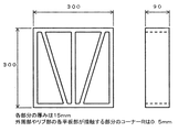
- FIG. 4 is a conceptual diagram of a rib structure molded body that was molded in the present invention and did not break even when left in a mold for a long period of time.
- the cast molded body of the present invention is a cast body of ceramic powder or metal powder, and the difference in the filling rate in the thickness direction is 0.05 or less, more preferably 0.025 or less.
- the filling rate of the cast molded body is the volume fraction of the powder occupied in the cast molded body after the cast molded body is dried.
- the filling rate of the cast molded body is the volume fraction of the powder occupied in the cast molded body after the cast molded body is dried.
- a cast molded body having a filling rate of 0.6 indicates that the constituent components of the cast molded body are 60 vol% powder and 40 vol% air.
- the cast molding usually has a distribution in the filling rate in the thickness direction, and here, the difference in the filling rate in the thickness direction in the present invention is defined as follows.
- the first is solid casting which allows the mold to absorb water from both sides of the cast body. This is also called double molding, and the part molded by this is called a double part.
- the cast molded body is sliced into five layers with a uniform thickness in the thickness direction, the respective filling rates are measured, and the portion showing the maximum filling rate (usually one layer in contact with the casting mold)
- the difference between the filling ratio in the thickness direction is defined as the difference between the portion having the minimum filling rate (usually the third layer in the center) and the portion having the minimum filling rate.
- the second is waste mud casting in which excess mud is discharged after water is absorbed into the mold from one side of the cast molding.
- This is also referred to as single molding, and a portion molded by this is called a single molding.
- the single part the remaining 80% thickness portion, excluding the portion corresponding to 20% of the thickness as a drainage portion with a large error, is sliced into 5 layers and the respective filling rates are measured, and the maximum filling rate is determined.
- the difference between the portion shown (usually the first layer in contact with the mold) and the portion showing the minimum filling rate (usually the fifth layer close to the drainage surface) is defined as the difference in filling rate in the thickness direction.
- many sanitary ware obtained by casting molding includes both a double part and a single part.
- the filling rate of each part can be calculated
- the filling rate is measured as follows. After the cast molding is completely dried at 120 ° C. (when the solvent is not water, the drying temperature is selected according to the boiling point of the solvent), the filling rate is measured by the Archimedes method.
- the filling rate of the cast molded body may be measured from a fired body obtained by firing the cast molded body.
- a fired body obtained by firing the cast molded body.
- the shrinkage during firing is almost zero. Therefore, if the volume ratio of each layer is obtained by observing the fired body with a scanning electron microscope (SEM) and the components constituting each layer are identified by X-ray diffraction (XRD) or Raman analysis, the filling rate of the cast molded body Can be obtained by calculation.
- the difference in the filling rate in the thickness direction of the cast molded body is 0.05 or less.
- the drying shrinkage in the mold can be made as small and uniform as possible.
- the difference in filling rate in the thickness direction is 0.025 or less.
- the difference in filling rate can be set to 0.01 or less.
- the difference in the filling ratio in the thickness direction varies depending on the type of the substrate, and the difference in the filling rate tends to be larger in the fine ceramic substrate than in the substrate containing a large amount of clay such as a ceramic substrate.
- the base material is substantially the same material, the base material whose plasticity is improved by adjusting the density or the like has a high compressibility, and therefore there may be a large difference in the filling rate in the thickness direction.
- the present invention as a preferable means of setting the difference in the filling ratio in the thickness direction of the cast molded body to 0.05 or less, more preferably 0.025 or less, it has self-water absorption and substantially water resistance.
- Means for producing a cast molded body by a casting mold having a water absorbing layer can be mentioned.
- the casting mold of the present invention includes a water absorbing layer.
- the water absorbing layer having “self-water absorbing property” means that the water absorbing property can be expressed by the capillary suction force of the water absorbing layer itself. is there.
- substantially water resistance means that it does not dissolve in water or react with water.
- a substantially water-resistant water-absorbing layer refers to a material that exhibits releasability when the surface dissolves in water, such as a gypsum mold, and a hydraulic material as a material for forming the water-absorbing layer. It means that it was not obtained using a material that reacts with water.
- a water-absorbing layer formed using a material that dissolves in water or reacts with water is not preferable because the surface of the water-absorbing layer deteriorates as the number of lives increases, and problems such as cracks and poor tightening occur.
- the casting mold of the present invention includes a water-absorbing layer having self-water absorption and substantially water resistance. More preferably, the water-absorbing layer of the casting mold has a porosity of 35 vol% or more and 50 vol% or less, an average pore diameter of 0.5 ⁇ m or more and 1.8 ⁇ m or less, and a particle size of 50% of the average pore diameter.
- the continuous pore volume is characterized in that the cumulative pore volume from the particle size to 150% is 60% or more of the total pore volume.
- porosity means the volume fraction of the pores of the water absorption layer, and is measured by the Archimedes method. It is also possible to measure the porosity with a mercury intrusion pore size distribution measuring device described later. The porosity values measured by both methods are almost the same.
- the porosity of the preferred water absorbing layer is 35 vol% or more. Thereby, the productivity which can ensure a sufficient water absorption speed is obtained.
- the absolute value of the filling rate of the cast molded body can be increased, and the partial difference in the filling rate of the cast molded body can be decreased, thereby improving the yield and reducing the shrinkage of firing.
- the preferred water absorption layer has a porosity of 50 vol% or less. Thereby, sufficient mold strength is obtained, and the risk of breakage during molding or molding is reduced.
- the “average pore diameter” means a pore diameter corresponding to a cumulative pore volume of 50% obtained using a mercury intrusion pore diameter distribution measuring device (commonly referred to as a porosimeter).
- the average pore diameter of the preferred water absorption layer is 0.5 ⁇ m or more. More preferably, it is 0.7 ⁇ m or more. Thereby, the water permeation resistance of the casting mold can be reduced, and the water flow amount at the time of water film demolding described later can be sufficiently secured. Further, even if the mold number increases, clogging of the water absorption layer is less likely to occur.
- the average pore diameter of a preferable water absorption layer is 1.8 micrometers or less. More preferably, it is 1.4 ⁇ m or less. Thereby, the capillary suction force can be sufficiently secured to improve the productivity. Further, the absolute value of the filling rate of the cast molded body can be increased, or the partial difference in the filling rate of the cast molded body can be decreased to improve the yield and reduce the firing shrinkage.
- the ratio of the cumulative pore volume to the total pore volume from 50% of the average pore diameter to 150% of the average pore diameter (hereinafter also referred to as “V50-150”) is the above-mentioned method.
- the cumulative pore volume from 50% to 150% of the determined average pore diameter (for example, 0.5 to 1.5 ⁇ m if the average pore diameter is 1 ⁇ m) refers to the ratio of the total pore volume.
- the total pore volume refers to the sum of the volumes of all pore portions of the water absorption layer.
- V50-150 is 60% or more. More preferably, it is 80% or more. Thereby, the balance of water absorption speed and water permeability at the time of water film demolding can be adjusted, and both productivity and demoldability can be set to appropriate values.
- the upper limit of V50-150 is not limited and may be 100%, but 99% is the upper limit of the range that can be controlled with industrially inexpensive molding costs.
- the casting mold of the present invention may be composed only of a water absorption layer.
- the casting mold of this invention has a water absorption layer and a reinforcement layer, and this reinforcement layer may be formed in the back surface of a water absorption layer.
- the back surface of a water absorption layer points out the surface on the opposite side to the wall surface (it is also mentioned a molding surface) among water absorption layers.
- This reinforcing layer is formed to support and reinforce the water absorbing layer.
- this reinforcing layer for example, concrete, FRP, FRC, metal, plastic, or the like can be used.
- Such a reinforcing layer may be reinforced by inserting a reinforcing bar or the like.
- examples of the material for forming the water absorption layer include a sintered metal mold, a ceramic mold, and a resin mold.
- the manufacturing principle and pore structure creation principle of sintered metal molds and ceramic molds are almost the same.
- Metal particles and ceramic particles are molded into a water-absorbing layer shape, and the molded body is sintered to fuse the particles together.
- the gap can be a pore.
- the porosity and pore size distribution can be controlled by controlling the particle size, sintering temperature, and sintering time of the particles.
- the pore size of the particles is reduced, the pore size is also reduced, and if the particle size distribution of the particles is sharpened, the pore size distribution is also sharpened.
- the porosity is determined by the porosity inherent in the compact of metal particles / ceramic particles and the degree to which the pores are closed by sintering. Therefore, if the compact filling factor is small, the porosity is large, and if the sintering temperature is high and the sintering time is long, the porosity is small. In a preferable range of the porosity of 35 vol% or more and 50 vol% or less, it is desirable to reduce the shrinkage caused by the progress of sintering by making the compact filling rate as close as possible to the target filling rate.
- water-resistant metal particles and ceramic particles that are raw materials for sintered metal molds and ceramic molds, and the sintered metal molds and ceramic molds that are sintered thereby must also be water resistant. Can do. Also, when using auxiliary materials / additives at the time of molding / firing as raw materials, water-resistant auxiliary materials / additives must be used unless they are volatilized during sintering or change to water-resistant components. Don't be.
- the mold strength may not be sufficiently secured. Many. Therefore, firing shrinkage often occurs in sintered metal molds and ceramic molds, but it may be technically difficult to obtain dimensional accuracy of the mold due to the firing shrinkage.
- the resin mold does not have a sintering process, it has a merit that it is easy to obtain dimensional accuracy and can be formed by pouring a material for forming the mold.
- the sintered metal mold and the ceramic mold are superior to the resin mold, and thus have advantages and disadvantages.
- the resin itself must not dissolve or react with water, and as a resin mold raw material, use a filler that dissolves in water or reacts with water. Must not. Therefore, do not use water-soluble ones such as gypsum, or ones that react with water, such as alumina cement or Portland cement.
- a filler having substantially water resistance the water resistance of the water absorbing layer can be improved.
- fillers having substantially water resistance such as silica sand, silica powder, alumina, zircon, glass beads, glass balloon, glass cullet, and frit glass can be preferably used.
- the glass must not dissolve in water as a glass composition.
- the molding surface which has water resistance can be formed, and it becomes possible to prevent generation
- resin-type water-absorbing layers including emulsion polymerization from O / W type emulsion slurry, method of inversion emulsion polymerization from W / O type emulsion, solvent
- a method of mixing a soluble component in a raw material and removing the soluble component with a solvent after curing can be given.
- an O / W type emulsion slurry in which a resin phase (oil phase) is dispersed in an aqueous phase is prepared, and this O / W type emulsion slurry is cast into an impermeable mold and cured in a water-containing state.
- this method the portion of the aqueous phase that is a continuous layer becomes continuous pores, and thus the porosity can be controlled by controlling the amount of water in the emulsion slurry.
- the pore size distribution of the created water-absorbing layer porous body can be adjusted. It can also be controlled.
- the pore size distribution of the water-absorbent layer porous body created can be controlled by controlling the filler particle size distribution. You can also By using these molds, the filling rate of the cast molded body can be made uniform. Therefore, it is possible to prevent the cast molded body from being cut at the time of casting, and to increase the yield.
- the reason why such an effect can be obtained is considered as follows, but is not limited thereto. It is considered that the filling rate of the cast-molded body is determined by the compression pressure at the time of inking. Since the casting mold of the present invention has self-water absorption and substantially water resistance, it is considered that pressure loss on the molding surface can be reduced at the time of fleshing. Therefore, it is considered that the filling rate of the cast molded body can be made uniform.
- the compression pressure applied to the molded body at the time of fleshing is also a function of the pressure loss in the molded body determined by the capillary suction force determined by the porosity and pore size distribution of the water-absorbing layer and the filling rate distribution of the molded body,
- pressure loss does not occur on the wall surface, and for this purpose, a water absorbing layer is formed so that a heterogeneous layer due to dissolution of the mold material cannot be formed on the mold surface. It is thought that the material constituting the water must be water resistant.
- the water absorption layer itself must be considered in terms of strength, ventilation and water permeability when removing the water film.
- a water absorption layer with a very small pore diameter to obtain a strong capillary suction is Aeration and water permeability are poor.
- the casting mold of the present invention can be provided with means for supplying pressurized water or pressurized air.
- Specific means for supplying pressurized water or pressurized air include a method of providing an air groove inside or on the back surface of the water absorption layer, a method of providing a coarse porous layer on the back surface of the water absorption layer, and the like.
- Examples of the case where pressurized water or pressurized air is supplied to the casting mold include the following cases.
- the water film mold release which applies a back pressure to a casting mold and blows out water and air between a casting mold and a molded object and demolds is mentioned. In this case, it is usually preferable to supply pressurized air to the water absorption layer.
- the sealing layer can be formed by applying a material such as resin on the back surface of the casting mold and curing it.
- a reinforcing layer of the sealing layer may be provided on the outside of the sealing layer with FRP, concrete, FRC, metal, plastic, or the like.
- the method for preventing the occurrence of breakage during molding by setting the difference in the filling rate in the thickness direction of the cast molded body to 0.05 or less, more preferably 0.025 or less has been described.
- the following steps (1) to (4) are carried out in this order, whereby a difference in filling rate of each part of the cast molded body is small.
- a molded body can be manufactured.
- (1) The step of controlling the water saturation of the water-absorbing layer having self-water absorption and substantially water resistance (2)
- the step of casting slurry in the casting mold (3) The slurry in the casting mold
- step (4) (a) a step of discharging excess slurry, and (b) a step of increasing the hardness by reducing the moisture content of the waste mud surface of the formed body. These steps can also be performed in this order.
- the step of controlling the water saturation rate of the water absorbing layer is a step of adjusting the water saturation rate of the water absorbing layer so that the deposition rate falls within an industrially appropriate range.
- the water saturation is preferably 30 to 80%, more preferably 40 to 60%.
- the rate of fleshing can be increased.
- the water saturation rate can be finely adjusted depending on the base for forming the cast molded body and the molding conditions. As a specific method for adjusting the saturation rate, the saturated water rate is almost 100% by injecting pressurized water into the casting mold until the desired saturation rate is obtained by injecting pressurized air thereafter.
- the saturation rate is calculated assuming that the saturation rate is 100% when the pores of the water absorbing layer are completely filled with water.
- the step of casting slurry in the casting mold is a step of casting slurry in the casting mold in which the saturation rate is controlled in this way.
- the step of depositing the slurry in the casting mold is a step of forming part of the slurry by solidifying the slurry by absorbing a part of the water contained in the slurry into the water absorption layer.
- the capillary suction force of a water absorption layer is made into the driving force of the main meat
- Another force may be used as a casting pressure for assisting the capillary suction force of the water absorption layer.
- a means for supplying pressurized water or pressurized air can be provided in the casting mold, and vacuum suction can be performed through the means.
- a peeling phenomenon may occur at the time of demolding in the next step. Therefore, it is preferable to stop the vacuum suction when the deposition time is 60 to 90%. Moreover, you may use the pressure (henceforth a head pressure) at the time of supplying mud from a pouring opening to a casting mold as casting pressure. Normally, since the head pressure is used as the pouring pressure into the slurry mold, this head pressure can be used as the casting pressure as it is.
- the slurry can be directly pressurized with a pump, piston, etc. in the process of depositing the slurry on the casting mold, but if this direct pressure is applied, the mold and molding apparatus must be pressure resistant and the cost is low. It becomes a factor of up. Since the present invention uses the water absorption force of the casting mold itself as the main driving force for the inking, it is preferable not to perform such direct pressure.
- the water absorption layer is open to the atmosphere including the earth closing time described below.
- a means for releasing the water absorption layer to the atmosphere there is a method of releasing the water absorption layer to the atmosphere by providing the above-mentioned means for supplying pressurized water or pressurized air to the casting mold and providing a pipe for opening the atmosphere to this means. it can. Therefore, it is preferable to provide the casting mold with means for performing a switchable operation of any one of (1) supply of pressurized water, (2) supply of pressurized air, (3) vacuum suction, and 4) release to the atmosphere. .
- the demolding time may be immediately after the end of the meat filling, or the mold can be demolded after a soiling time.
- the earth closing time is usually essential. By using means such as supplying pressurized air into the sludge space, a soil closing time is taken until a predetermined hardness is obtained.
- solid casting there is almost no shrinkage of the molded body during the earthing time, and no tightness occurs, so the earthing time is almost unlimited and may or may not be present.
- a preferable method for demolding includes water film demolding in which water is jetted between the mold and the molded body by supplying pressurized air or pressurized water to the mold.
- the difference in the thickness direction of the change from the end of the filling to the time of demolding is more preferably 0.05 or less by controlling the soil closing conditions. Is preferably 0.025 or less.
- the filling rate at the time of finishing the meat and at the time of demolding is the same definition as the filling rate when the molded body has been completely dried as described above, and only the part of the volume fraction other than the powder. Is the difference between air and water.
- the molded product at the end of the fleshing with a filling rate of 0.6 or at the time of demolding refers to that whose constituent fraction is 60 vol% of powder and 40 vol% of water.
- the measurement method is such that water is completely dried and the weight change is measured, and the volume fraction is calculated in consideration of the specific gravity difference between the powder and water.
- the finishing time is set to the time when the head drop during solid casting is substantially stopped.
- the term “substantially” as used herein refers to the time point when the molding has finished being thinned and the head drop is almost zero, and thereafter the head is lowered slightly due to the filling of the pouring port other than the molded article. It may continue. Also, since it may take some time to remove the molded product from the mold immediately after the end of the inking, the measured part is cut out from the formed body 5 minutes after the end of the inking to measure the filling rate. Thus, this is defined as the filling rate at the end of the inking.
- the time of demolding shall cut a measurement part from the molded object immediately after demolding, and shall measure a filling rate.
- the difference in the change in the thickness direction of the filling rate is defined in the same manner as the difference in the thickness direction of the filling rate when the molded body is completely dried. That is, the measurement part of the molded body at the end of the inking or at the time of demolding is sliced into five layers, and the respective filling rates are measured and evaluated.
- the difference in the thickness direction of the change in the filling rate from the end of the bedding to the time of demolding is, for example, 0.55 to 0. If it is changed to 6, the difference is 0.05, and if it is normally changed from 0.5 to 0.58 in the third largest layer, the difference is 0.08. Therefore, the difference in the thickness direction of the change in the filling rate from the end of the infilling to the demolding in this case is 0.03 obtained by subtracting 0.05 from 0.08.
- the tightening at the time of earth closing is controlled by controlling the preferable value of the difference in the thickness direction of the change from the end of the filling to the time of demolding to 0.05 or less, more preferably 0.025 or less.
- the occurrence of cutting can be prevented more reliably.
- there is no preferred lower limit of the difference in the thickness direction of the change from the end of the filling rate to the time of demolding it is industrially difficult to make it 0.001 or less.
- This preferred range is the same in all double parts as well as the double part close to the single part of the molded article having the single part and the double part, but the double part close to the single part is usually the most. Since the difference is large, this part is evaluated.
- control method of the earthing conditions for setting the difference in the thickness direction of the change in the filling rate of the double part from the end of the inlay to the time of demolding is 0.05 or less, more preferably 0.025 or less. It refers to such means.
- pressurized air is often supplied to the waste mud space mainly to harden the part of the single part that is particularly close to the sludge discharge surface.
- the pressure air pressure can be reduced to increase the pressurized air charging time.
- pressurized air is supplied only to the first part during soiling, and then the mud space is returned to atmospheric pressure.
- a technique of leaving the mold in the mold until it is slightly below the upper limit of the preferable range can also be used, which is effective when the molded body is left in the mold at night.
- a cast body of ceramic powder or metal powder according to the present invention wherein the difference in filling rate in the thickness direction is 0.05 or less, more preferably 0.025 or less.
- the molded body and its manufacturing method have been described. As described above, this is achieved by reducing the difference in the filling rate of each part of the molded body during molding and reducing the tensile stress due to the difference in drying shrinkage of each part. Its purpose was to prevent cutting.
- the cast molding with a small difference in the filling rate in the thickness direction and the manufacturing method thereof can exert a greater effect in the production of cast ceramics or metal powders with partially different thicknesses. Is possible. This is because, in cast moldings with partially different thicknesses, there is a large difference in the filling rate of the parts with different thicknesses, and there is a step at the boundary between the parts with different thicknesses. This is because it is more likely to occur.
- Examples of a method for producing a cast product having a partially different thickness include a method of using a water absorption layer having a difference in the thickness of the part in a casting mold.
- As an index representing the inking speed there is the inking speed constant, which is a value obtained by dividing the square of the inking thickness by the inking time, and is a constant that does not depend on the inking time.
- the inking phenomenon in casting is, in principle, a cake filtering operation, and the inking rate constant is proportional to the casting pressure.
- the square root of the capillary suction force can be approximated to the wall thickness within a certain time. The thickness of each part of the molded body can be adjusted.
- the uniformity of the filling rate of the part is also important, and preferably the difference in the filling rate between the adjacent thick part and the thin part is 0.05 or less. It is possible to keep the adjacent thick and thin portions within the preferred range by being manufactured by a casting mold having a water-absorbing layer having self-water absorption and substantially water resistance, The reason is the same as the reason why the filling rate in the thickness direction is uniform.
- the wall thickness is different, the compression pressure distribution in the molded body is different and the hurdle is further increased, so that the present invention can be suitably applied.
- the casting mold is configured as a plurality of split molds, and the water absorption layers of the plurality of split molds have different thicknesses. It is preferable that When it is configured as a split mold, a mold material having water resistance as in the present invention is preferable because the mold mating surface is hardly worn.
- FIG. 1 and FIG. 2 show specific examples of casting molds configured as a plurality of split molds and having different splitting rate.
- FIG. 1 shows a split mold having a water absorption layer 2 (hereinafter referred to as a high-thickness type water-absorbing layer) having a high flaking rate and a water-absorbing layer 1 (hereinafter referred to as a low-thickness type water-absorbing layer) having a low flaking rate.
- a cast molded body 3 is formed by exhaust mud casting using a casting mold having a split mold having a slag. Thereby, it is possible to obtain a hollow cylindrical cast body having a partially different thickness.
- FIG. 2 is a specific example in which a cast molded body 3 is formed by solid casting using a casting mold having a high-walled water-absorbing layer 2 and a low-walled water-absorbing layer 1. . Thereby, the cast molding which has a rib structure from which thickness differs partially can be obtained.
- the casting mold has a plurality of water absorption layers, and the plurality of water absorption layers have different thicknesses. It is preferable. In this case, it is possible to integrate and use a plurality of water-absorbing layers each having a different deposition rate. Using a plurality of water absorbing layers with different inking speeds in an integrated manner means that a plurality of water absorbing layers with different inking speeds are integrated so that the forming speed is partially different on the molding surface. Refers to that. As a result, cracks and the like due to the mold-joining surface are less likely to occur. FIG.
- FIG. 3 shows a specific example of a casting mold for waste mud casting in which a plurality of water absorption layers having different thicknesses are integrated.
- the casting mold shown in FIG. 3 is a specific example of a casting mold in which the high-walled mold water-absorbing layer 2 and the low-walled mold water-absorbing layer 1 are integrated. Thereby, the cast molding from which thickness differs partially can be obtained.
- the following methods can be used to integrally form the water-absorbing layers having different thicknesses.
- sintered metal molds and ceramic molds a plurality of ceramic powders and metal powders having different particle size distributions are used as raw materials, and after filling one raw material powder into a mold, the other raw material powder is filled, and then integrally A technique for sintering is mentioned.
- the resin mold since the raw material slurry is often a liquid, the following method is used. First, the resin mold slurry for forming the first water-absorbing layer is cast into an impermeable mold, and after the resin mold slurry loses fluidity, the second resin mold slurry is poured before it is completely cured. Mold and cure in one piece.
- the joint between the two types of resin molds may have insufficient strength.
- the joint surfaces of the two types of resin-type water-absorbing layers are lower than the strength of the respective water-absorbing layers. Therefore, after the surface of the first water-absorbing layer is roughened or uneven, It is preferable to take a method of pouring a resin type slurry for forming a water absorption layer.
- the following method can be used to integrally form the water absorption layers having different deposition rates for sintered metal molds and ceramic molds.
- a water absorption layer having a large flaking rate uses a metal powder or ceramic powder having a small particle size as a raw material
- a water absorption layer having a small flaking rate uses a metal powder or ceramic powder having a large particle size as a raw material.
- a metal powder molded body or a ceramic powder molded body using each powder is integrally molded or joined and sintered simultaneously.
- a method of integrally molding a metal powder molded body or a ceramic powder molded body As a method of integrally molding a metal powder molded body or a ceramic powder molded body, a method is adopted in which after molding one molded body and placing the molded body in a mold, the other molded body raw material is cast. be able to. Moreover, you may join both the molded objects using the adhesive paste which added the adhesive agent, the solvent, etc., and was made into the paste-like form, and a component is substantially equal to each molded object. Further, it is possible to join the sintered metal water absorption layer or the ceramic water absorption layer after sintering if the bonding strength is not so required.
- the above-described water absorbing layer used in the casting mold of the present invention can be used. This is because the above-mentioned water absorption layer used in the casting mold of the present invention can be controlled in a wide range of the rate of walling, and thus is suitable for producing molded bodies having partially different thicknesses.
- a means for controlling the capillary suction force of the water-absorbing layer may be mentioned as a means for controlling the rate at which the water-absorbing layer is deposited. Since the capillary suction force of the water absorption layer is inversely proportional to the tube diameter, the capillary suction force can be adjusted by controlling the pore diameter of the water absorption layer porous body.
- Examples of means for controlling the capillary suction force of the water-absorbing layer include the above-mentioned means for controlling the pore diameter of the water-absorbing layer, and control within a preferable pore diameter range of 0.5 ⁇ m to 1.8 ⁇ m. Can do.
- the water absorption layer has a partially different walling speed. It is possible to produce cast moldings having different thicknesses. By using such a casting mold, it is possible to obtain a cast molded body with a uniform filling rate. Variations in drying shrinkage and firing shrinkage of the portion can be reduced. Therefore, generation
- any kind of powder can be used for the cast-molded body in the present invention.
- what is important as an industrial application field is a cast body of ceramic powder or metal powder.
- the cast molding obtained by casting molding powder can be baked, and can be utilized as a sintered body.
- Ceramics powders for the production of ceramics such as sanitary ware, tableware, insulators, tiles, mixed powders such as silica sand, feldspar, clay, alumina, silicon carbide, silicon nitride, boron carbide, aluminum nitride, sialon, zirconia Monolithic ceramic powders such as mullite, and composite ceramic powders obtained by mixing them can be used.
- powder for producing a reaction sintered body such as reaction sintered silicon carbide, a reaction sintered silicon carbide and boron carbide composite, reaction sintered silicon nitride, or the like can also be used.
- Metals include pure iron, iron-copper, iron-carbon, iron-carbon-copper, iron-carbon-copper-nickel, iron-carbon (copper infiltration), iron-nickel, iron -Carbon-nickel, iron-nickel-molybdenum-carbon, iron-manganese-chromium-carbon, iron-copper-nickel-molybdenum-carbon, stainless steel, high-speed steel, pure copper, bronze, brass, silver, aluminum Bronze, silgin bronze, nickel bronze, phosphor bronze, monel, temperloy, aluminum and its alloy, titanium and its alloy, superalloy, tungsten and its alloy, cemented carbide, cermet and the like can be used.
- the cast molded body when the cast molded body is fired and used as a fired body, since the cast molded body has a high filling rate and a uniform filling rate of each part of the cast molded body, the shrinkage during firing is small. It becomes possible for the part to shrink uniformly. Therefore, there are advantages in that cracks due to firing hardly occur and that dimensional stability is high.
- the cast molding has a high filling rate and the filling rate of each part is uniform, so that the sintering proceeds sufficiently. It is easy, and physical properties such as strength after sintering can be made high and uniform.
- the mold design is such that the inking is completed at approximately the same time for each part with different thickness of the cast molding Is preferably performed.
- the thickness ratio between the adjacent portions is not more than 5 times that of the thin portion.
- the thickness of the thick part is 1.25 times that of the thin part. The above is preferable. More preferably, it is 1.5 times or more.
- the ratio of the thickness between the double parts there is a preferable range and a high practical range in the single part of the sludge cast molding as well.
- the ratio of the thickness of the adjacent part is The thick part is preferably 4 times or less than the thin part.
- the boundary between the portions having different thicknesses becomes a gentle R portion. Therefore, by joining three or more layers of water absorbing layers having different thicknesses, the above-mentioned 2 through the almost continuous smooth R portion.
- the molded body can also be designed so as to have a thickness ratio of 5 times or more, which is a preferable upper limit thickness ratio of the heavy portion. The preferred lower limit is the same as in the case of solid casting.
- sanitary ware In these powder sintered bodies, if there are portions having different thicknesses, sanitary ware, engineering ceramics, and the like are preferable examples.
- the thickness of the trap part In sanitary ware, the thickness of the trap part is controlled to control the flow of cleaning water, and only the parts that are likely to be fired and deformed are thickened and the remaining parts are thinned to create a sharp shape and design. It is possible to reduce the weight.
- engineering ceramics it is possible to reduce the weight by controlling the thickness to ensure the strength of the necessary part.
- translucent ceramics such as a metal halide lamp, the functions of brightness and productivity can be achieved by controlling the thickness of the light emitting portion and the sealing portion.
- the present invention also relates to a casting apparatus for ceramic powder or metal powder, comprising a molding machine capable of performing each step of the above-described method for producing a cast molded body, and the above casting mold. Providing casting equipment.
- Tables 1 and 2 show physical properties of casting molds 1 to 21 used as examples and comparative casting molds 1 to 8 used as comparative examples.
- the raw materials used for the casting molds 1 to 21 are a water-resistant epoxy resin and a water-resistant filler.
- the fillers used are casting molds 1 to 14 and casting molds 17 to 21 are silica sand powder, and casting molds 15 and 16 are alumina.
- the casting mold 1 for a comparative example is a gypsum mold that is usually used industrially, and is a gypsum mold that is manufactured using ⁇ -type hemihydrate gypsum manufactured by San-S Gypsum Co., Ltd.
- the raw material used for the casting molds 2 and 3 for comparative examples is a mixture of a water-resistant epoxy resin mixed with a water-resistant filler and a non-water-resistant filler.
- silica sand is used as the filler having water resistance
- hemihydrate gypsum is added as a raw material in the casting mold 2 for the comparative example
- Portland cement is used as the raw material in the casting mold 3 for the comparative example as the filler having no water resistance.
- the raw materials used for the comparative casting molds 4 to 8 are a water-resistant epoxy resin and a water-resistant filler.
- the casting molds for comparative examples 4, 5, 6, and 8 are silica sand powder
- the casting mold for comparative example 7 is alumina.
- a test piece having a head speed of 2.5 mm / min was vacuum-sucked for 30 minutes, then submerged and further vacuum-suctioned for 30 minutes.
- the inking rate constant A (10 ⁇ 2 mm 2 / sec) was calculated by the following method. 1) A 100 mm ⁇ ⁇ 30 mmt casting mold test piece was adjusted to have a saturation rate of 50%. 2) An acrylic tube with a diameter of 60 mm was set up on the test piece, and Vitreas China sludge (specific gravity 1.8) for large sanitary ware was poured into the acrylic tube to a depth of 50 mm.
- the inking rate constant B (10 ⁇ 2 mm 2 / sec) is 3) in (Note 5), from 1 minute after the start of the inking time to 85% of the inking time t, that is, 0. Calculations were made in the same manner as in (Note 5) except that the test piece was vacuumed up to 85 ⁇ t seconds. During vacuum suction, the pressure between the vacuum pump and the test piece was set to 0.01 to 0.015 MPa.
- the inking rate constant C (10 -2 mm 2 / sec) is the same as in (Note 5) 2) except that high-purity alumina slurry (specific gravity 2.5) for large products is used as the slurry (Note 5). ).
- the inking rate constant D (10 -2 mm 2 / sec) is the same as that in (Note 5) 2) except that iron powder slurry (specific gravity 4.2) is used as the slurry. Calculation was performed in the same manner as in 5).
- the amount of water flow was measured by the following method. 1) In a casting mold test piece of 100 mm ⁇ ⁇ 30 mmt, the side surface was completely sealed so that water did not come out from the side surface, and then completely saturated. Here, the completely saturated state refers to a state in which all pores are filled with water. 2) A water pressure of 0.3 MPa was applied from one end, and the amount of water discharged from the other end until 15 seconds after the start of applying the water pressure was measured.
- the test piece was vacuum sucked from 1 minute after the start of the setting time to 85% of the setting time.
- the pressure during vacuum suction was such that the pressure between the vacuum pump and the test piece was 0.01 to 0.015 MPa.
- the test piece was dried at 40 ° C. for 24 hours before pouring the slurry.
- the casting mold 7, and the comparative casting mold 6, the saturation rate was adjusted to 50% before the slurry was poured. After completion of 20 mm thickening corresponding to the thickness of the PVC pipe, the mold was removed, and the molded body in the PVC pipe was dried at 40 ° C. overnight.
- the molded body was removed from the polyvinyl chloride tube and dried at 120 ° C. for 12 hours. Thereafter, a cast molded body of 20 mm * 20 mm was cut out from the center part of the cast molded body having a thickness of 20 mm to obtain cast molded bodies of Examples 1 to 4 and Comparative Examples 1 to 4.
- Each cast molding was sliced into five layers, and the filling rate was measured by Archimedes method.
- the respective filling points are A, B, C, D, and E (where A and E are in contact with the mold and C is the central part), and the obtained filling rate and the maximum and minimum values of the filling rate obtained. The difference in values is shown in Table 3.
- Test pieces of 100 mm ⁇ ⁇ 30 mmt were prepared using the mold materials of the casting mold 4, the casting mold 7, the comparative casting mold 1, and the comparative casting mold 6.
- the saturation rate was adjusted to 50% before the slurry was poured.
- the test piece was dried at 40 ° C. for 24 hours before pouring the slurry.
- a 60 mm ⁇ acrylic tube was erected on each test piece, and slurry was poured into the acrylic tube to a depth of 50 mm.
- the test piece was vacuumed from 1 minute after the start of the setting time to 85% of the setting time.
- the pressure during vacuum suction was such that the pressure between the vacuum pump and the test piece was 0.01 to 0.015 MPa.
- the saturation rate was adjusted to 50% before pouring the slurry.
- the mold was removed, and the molded body in the PVC pipe was dried at 40 ° C. overnight. Thereafter, the molded body was removed from the polyvinyl chloride tube and dried at 120 ° C. for 12 hours.
- Test pieces of 100 mm ⁇ ⁇ 30 mmt were produced in the following order using the casting mold 1 and casting mold 7.
- a casting mold for producing a test piece of 100 mm ⁇ ⁇ 30 mmt was divided into a half-moon shape by a partition at the center, and a resin mold slurry as a raw material of the casting mold 1 was first cast on one side. Then, after the semi-cured state was reached in a state where water contained in the slurry did not evaporate, the partition was removed, and the resin-type slurry as the raw material of the casting mold 7 was cast on the other half-moon part. Thereafter, in a state where the water contained in the slurry does not evaporate, it was completely cured in a water-containing state, and after curing, it was demolded to obtain a test piece of a casting mold.
- a test piece of 100 mm ⁇ ⁇ 30 mmt was produced by the same method using the mold materials of the comparative casting mold 6 and the comparative casting mold 7.
- a 60 mm ⁇ acrylic tube was placed on each of the obtained test pieces, and Vitreas China sludge for large sanitary ware was poured into the acrylic tube to a depth of 50 mm (Note 5). When observed from the outside of the acrylic tube, it was allowed to stand on the casting mold 7 portion and the comparative casting mold 7 portion until it appeared to be 15 mm thick. After that, the unfilled mud was drained, and after casting, demolding and drying, a cast product was obtained. Moreover, the obtained cast product was fired at a normal firing temperature for sanitary ware having a maximum temperature of 1180 ° C. to obtain a fired body.
- the cast moldings molded with the test pieces of the casting mold 1 and the casting mold 7 had no cracks or defects.
- the filling rate of each part of the cast molding was measured, it was 0.649 in the casting mold 1 part and 0.67 in the casting mold 7 part. There were no cracks or defects in the fired body after firing.
- the cast moldings molded with the test pieces of the comparative casting mold 6 and the comparative casting mold 7 are cracked and deformed on the joint surface of the mold, and the thickness is accurately increased. It was not possible to measure.
- the filling rate of each part of the cast molding was measured, it was 0.613 for the comparative casting mold 6 and 0.668 for the comparative casting mold 7.
- the thickness of the plate-like molded body was 5 mm for the casting mold 1 and 25 mm for the casting mold 7, and the thickness was varied with the center as the boundary.
- the stepped portion at the boundary with different thickness was set to about 1.5 mmR.
- a solid cast molding gypsum mold for molding a 200 mm ⁇ 200 mm plate-shaped cast molded body using the mold material of the comparative casting mold 1 was produced.
- the thickness of the plate-like molded body was set to be different from the center as a boundary, so that the half was 10 mm and the other half was 12.5 mm.
- the boundary between the portions having different thicknesses was set to about 1.5 mmR.
- the cast solids were obtained by pouring the vitreous china sludge for large sanitary ware (Note 5) into each of the solid casting molds obtained.
- the casting mold for producing the rib structure molded body shown in FIG. 4 has a casting mold 4 as a water-absorbing layer, a casting mold 7, a casting mold 1 for comparative examples, and a casting mold for comparative examples. Each was produced using the mold material of mold 6.
- the casting mold 4, the casting mold 7, and the comparative casting mold 6 are vertically split and the rib portion is integrated with the upper mold, and the comparative casting mold 1 is vertically , It was divided into 8 parts with 2 sides and 4 ribs.
- the demolding method is a casting mold 4, casting mold 7, and comparative casting mold 6 is a water film demolding method in which back pressure is applied to each split mold by pressurized air supply means. As for the casting mold 1, only the rib part was air-injected into the gypsum split mold.
- the solid casting was performed using the high-purity alumina slurry for large products (Note 7) for each mold. After completion of the meat deposition, the soiling time was left under 5 conditions of 10 minutes, 30 minutes, 2 hours, 24 hours, and 72 hours, and then the mold was removed. The water-absorbing layer was opened to the atmosphere during the time of meating and soiling. As a result, in the casting mold 1 for the comparative example, undercut conditions occurred in almost all the corner R portions, and under the conditions of 10 minutes, the base was soft and deformed during demolding.
- the corner R portion was not cut off only under the condition of 10 minutes of the earth tightening, but the base material was soft, so that deformation occurred at the time of demolding. Cutout occurred in almost all parts.
- the casting mold 4 and the casting mold 7 no breakage occurred at all earthing conditions, and no deformation occurred at the time of demolding. And although the molded object obtained with the casting mold 4 and the casting mold 7 was dried and baked, the fault did not generate
- the outer size is 300 mm x 300 mm x 80 mm, and the mold is placed so that the size in the vertical direction (gravity direction) is 80 mm at the time of molding. It has both a single part and a double part, and the thickness of the double part Is 10 mm, and the maximum thickness in the longitudinal direction (gravity direction) of the single-part sludge space is 64 mm when the single-part thickness is 8 mm.
- Each was produced using the mold materials of the mold 4 and the casting mold 1 for the comparative example. Subsequently, a molded body was prepared by using water in which the specific gravity was set to 1.74 by adding water to the large sanitary ware vitreous china slurries of (Note 5).
- the mud was drained after the single part was made to be 8 mm thick. Subsequently, the soil pressure was controlled by variously controlling the air pressure and the time to apply air pressure to the sludge space as the soil tightening conditions. No soil closing condition was found.
- the cast mud 4 was used to drain the mud until the single part became 8 mm. Subsequently, as the soil tightening conditions, the air pressure and the time during which the air pressure was applied were variously controlled, and after performing the soil tightening under the condition that the deformation of the molded body did not occur at the time of the mold release, the mold was removed. A 10 mm ⁇ 10 mm molded body was cut out from a portion 5 mm away from the single part of the double part of the molded body immediately after demolding and sliced into 5 layers, and the filling rate was measured. In addition, each part shall be displayed in order as A, B, C, D, and E (the part where A and E are in contact with the mold is the top).
- Table 6 shows the change in the filling rate distribution of each molded body at the time of soil tightening under the respective soil tightening conditions and the occurrence of the tightness of the molded body.
- a cast-molded body having a uniform filling rate can be manufactured with a high yield. Moreover, the manufacturing method of the cast-molding body from which thickness differs partially can be provided.
Landscapes
- Engineering & Computer Science (AREA)
- Chemical & Material Sciences (AREA)
- Ceramic Engineering (AREA)
- Dispersion Chemistry (AREA)
- Manufacturing & Machinery (AREA)
- Mechanical Engineering (AREA)
- Producing Shaped Articles From Materials (AREA)
- Powder Metallurgy (AREA)
Abstract
セラミックス粉体または金属粉体の鋳込成形体であって、その厚み方向の充填率の差が0.05以下、さらに好ましくは0.025以下であることを特徴とする鋳込成形体を提供する。
Description
本発明は、セラミックス粉体または金属粉体の鋳込成形体とその製造方法に関する。
鋳込成形とは、粉体と溶媒を混合した泥漿を、多孔質層を有する鋳込成形型に注型し、多孔質層に溶媒の一部を吸収させて固化させること(これを着肉という)により鋳込成形体を作製する方法である。鋳込成形は、衛生陶器や大型エンジニアリングセラミック部材のような大型複雑形状部材などの成形方法として多用されている。なお、溶媒の具体例として水を記載するが、水以外に有機溶媒を用いることもできる。したがって、吸水性には有機溶媒を吸収することも含むものとする。
このスラリー中の水分が鋳込成形型の多孔質層に移動する駆動力を鋳込圧という。鋳込圧は、多孔質層の毛管吸引力、泥漿への直接加圧力、泥漿のヘッド圧、多孔質層を真空ポンプ等で吸引する場合の吸引力等を足し合わせることにより求めることができる。なお、通常は、毛管吸引力もしくは泥漿への直接加圧が主であり、泥漿のヘッド圧、吸引力は絶対値が小さいため補助的な役割として用いられる。ただし泥漿の直接加圧による加圧鋳込成形は型や成形機を耐圧仕様にしなければならないため高イニシャルコストであり、よほどの大量生産品でないと適用できない。そこで通常の鋳込成形の鋳込み圧は多孔質層の毛管吸引力が主として用いられる。
この鋳込成形型の材料(以下、型材ともいう)として、従来、石膏が用いられてきた。その理由として、安価であることや造型が簡単であること等があげられるが、特に下記の二つの利点を兼ね備えていることが考えられる。
まず、第一の利点として、自己吸水性を有することが挙げられる。自己吸水性は、石膏型の原料である半水石膏が水和する際に二水石膏の微細な結晶の絡み合いにより毛管吸引力を発現することにより発生する。したがって、鋳込成形型そのものが鋳込圧を発現するため、泥漿への加圧のようなコストのかかる操作が不要である。
また、第二の利点として、離型性が優れていることが挙げられる。離型性は鋳込成形型の成形面の表面を鋳込成形体と共に剥離させることにより発現する。石膏は耐水性に劣っているために表面が少しずつ水に溶解するため、離型性に優れている。
このように石膏による鋳込成形型には自己吸水性と優れた離型性という二つの利点があるが、欠点もある。即ち、鋳込成形型の成形面の表面を溶解させて離型性を発現しているため、何回も成形しているうちに、表面の磨耗がひどくなる。また気孔内部も表面が水溶することにより毛管径が大きくなり十分な毛管吸引力を発現しなくなる。よって、型命数(すなわち、一つの型で製作できる製品個数)は80~150回位に過ぎない。また、磨耗した型を使うと鋳込成形体の品位が低下し、歩留低下を引き起こす。さらに、着肉終了後の土締め工程や乾燥工程において収縮のため切れが多発し、成形工程や焼成工程でのクラック発生につながる。
以上のように、石膏による鋳込成形には切れの発生や表面磨耗による低歩留、低型命数という問題点がある。これらの問題点を解決する成形方法として、耐水性と自己吸水性を有する型材を用いた成形方法が提案されている(例えば、特許文献1参照)。
また、近年、大型複雑形状の製品を簡便に製造するために、部分的に厚みが異なる鋳込成形体の製造方法が求められている。
鋳込成形は、流動性のある泥漿を鋳込成形型に流し込むことにより、鋳込成形型の形状を忠実に写し採ることができるため、大型複雑形状の製品を成形するのに向いている。その一方、部分的に厚みが異なる鋳込成形体を製作するのは難しいという欠点がある。これは鋳込成形では部分的に鋳込み圧を変えて着肉速度を変えることが難しいためである。
例えば、石膏成形においては石膏の毛管吸引力は二水石膏結晶のからみあいの間隙の毛管径によって決まる。この二水石膏結晶は半水石膏スラリーからの二水石膏析出によるものであり、その毛管径のコントロールは非常に難しく、また広い範囲で毛管径をコントロールすることはできない。
また加圧鋳込成形においては、パスカルの原理により泥漿にかかる圧力はどの部分も常に一定であるため、鋳込圧はどの部分も一定となり、部分的に厚みを変えた鋳込成形体を作製することはできない。よって、ピストンによる加圧や、泥漿の一部に加圧エアーを接触させることにより泥漿に圧力をかけても、鋳込圧はどの部分も一定となる。
そのため、従来厚みが部分的に異なる成形体を製作する方法として、例えばCIP成形により製作した単純形状の成形体を研削により削りだすといった手法が用いられていた。この方法では、鋳込成形に比べると研削費や研削により廃棄される部分の材料費などで高コストになるという問題点があった。
鋳込成形により部分的に厚みが異なる鋳込成形体を製造する方法として、以下の方法が知られている。
特許文献2には、排泥鋳込成形法において、一回目の着肉終了後に、厚肉構造としたい部分に堰を設け、この堰内に泥漿を注入して二回目の着肉を行う方法が記載されている。
特許文献3には、排泥鋳込成形法において、溶媒吸収力に差がある鋳込成形型を用い、泥漿が充填されたキャビティー内の圧力を位置によって変化させるという方法が記載されている。
特許文献4には、鋳込成形型内に反応焼結セラミックスの小片を充満してから原料スラリーを注型し、小片がスラリーの水を吸収することにより部分的に厚みが異なる成形体を作製する方法が記載されている。
しかしながら、上記で挙げた先行文献には以下のような問題がある。
すなわち、特許文献1の方法は、鋳込成形体の各部分の充填率の差が大きいため、成形工程や焼成工程で切れが多く発生してしまうおそれがある。
特許文献2の方法は、固形鋳込に対応することができないという問題がある。また厚肉としたい部分を1回目の着肉終了後に形成するため鋳込成形体の形状に制約があるという問題がある。
特許文献3の方法は、溶媒吸収力に差がある鋳込成形型や圧力を位置によって変化させる手段について、具体的に記載されておらず、実施が難しいという問題がある。
特許文献4の方法は、反応焼結窒化珪素以外の材質には応用できないという問題がある。
以上のように、石膏による鋳込成形の低歩留、低型命数という問題点を解決することは特に切れ発生を防止する点で難しい。また、従来知られている鋳込成形により部分的に厚みが異なる鋳込成形体を製造する方法は、鋳込成形体の形状に制限があったり、材料が限定されていたり、実用的に利用できるものではない。
本発明は、上記問題を解決するためになされたもので、本発明は、充填率が均一で切れが発生しない鋳込成形体を製造すること、および部分的に厚みが異なる鋳込成形体を製造することを目的とする。
上記目的を達成するために本発明の鋳込成形体はセラミックス粉体または金属粉体の鋳込成形体であって、その厚み方向の充填率の差が0.05以下であることを特徴とする。
また本発明の鋳込成形体は部分的に厚みが異なるセラミックス粉体または金属粉体の鋳込成形体であって、その隣り合う厚肉部分の厚みと薄肉部分の厚みの比率が1.25倍以上5倍以下であることを特徴とする。
本発明によれば、充填率が均一で切れが発生しない鋳込成形体を製造することができる。また、部分的に厚みが異なる鋳込成形体を高歩留で製造することができる。
本発明の鋳込成形体はセラミックス粉体または金属粉体の鋳込成形体であって、その厚み方向の充填率の差が0.05以下、さらに好ましくは0.025以下であることを特徴とする。
ここで、鋳込成形体の充填率について説明する。鋳込成形体の充填率とは、鋳込成形体を乾燥させた後の鋳込成形体中に占める粉体の体積分率である。例えば充填率0.6の鋳込成形体とは鋳込成形体の構成成分が粉体60vol%、空気40vol%のものを指す。また鋳込成形体の種類によっては有機バインダーなどの粉体以外の成分を含むものもあるが、本発明においては、これも粉体体積の一部としてカウントするものとする。
鋳込成形体は通常厚み方向の充填率に分布を持っており、ここで本発明における厚み方向の充填率の差を以下のように定義する。
鋳込成形の方法には、2種類ある。1つ目は、鋳込成形体の両側から型に吸水させる固形鋳込成形である。これは2重成形ともいい、これにより成形された部分を2重部と呼ぶ。2重部においては、厚み方向に鋳込成形体を均等厚みに5層にスライスしてそれぞれの充填率を測定し、最大充填率を示す部分(通常は鋳込成形型に接している1層目または5層目である)と最小充填率を示す部分(通常は中央の3層目である)の差を厚み方向の充填率の差とする。
2つ目は、鋳込成形体の片側から型に吸水させた後に余剰泥漿を排出する排泥鋳込成形である。これは、1重成形ともいい、これにより成形された部分を1重部と呼ぶ。1重部においては、誤差が大きい排泥部分として厚みの20%に相当する部分を除いた残り80%の厚みの部分を5層にスライスしてそれぞれの充填率を測定し、最大充填率を示す部分(通常は型に接している1層目である)と最小充填率を示す部分(通常は排泥面に近い5層目である)の差を厚み方向の充填率の差とする。
例えば、鋳込成形により得られた衛生陶器は、多くが2重部と1重部の両方を含む。この場合、それぞれの部分の充填率は、上記の方法に基づいて求めることができる。
本発明において、充填率の測定方法は下記の通りとする。鋳込成形体を120℃で完全乾燥させた後に(溶媒が水でない場合には、溶媒の沸点に応じた乾燥温度を選択する)、アルキメデス法によって充填率を測定する。
なお鋳込成形体を構成する材料によっては、鋳込成形体を焼成して得られる焼成体からも鋳込成形体の充填率を測定できる場合もある。例えば、材料として反応焼結炭化珪素や反応焼結窒化珪素を用いた場合、焼成時の収縮はほぼ0である。したがって、焼成体を走査型電子顕微鏡(SEM)観察などにより各層の体積比を求め、さらにX線回折(XRD)やラマン分析により各層を構成する成分を同定すれば、鋳込成形体の充填率を計算により求めることが可能となる。
本発明において、鋳込成形体の厚み方向の充填率の差は0.05以下である。これにより、型内での乾燥収縮をなるべく小さく、また均一にすることができる。好ましくは、厚み方向の充填率の差は0.025以下である。これにより、確実に締り切れ防止を達成することができる。これは型内の成形体内各部の乾燥収縮の不均一に起因する引っ張り応力の発生が締り切れ発生の要因であるためであり、乾燥収縮は成形体の充填率の変化で計算できるため成形体の各部分の充填率が均一であれば締り切れの発生を防ぐことができるのである。また圧縮性の小さな材料であれば、この充填率の差を0.01以下にすることも可能である。当然ながらこの厚み方向の充填率の差には好ましい下限は存在しないが、0.001より小さくすることは工業的に難しい。またこの厚み方向の充填率の差は素地の種類によっても異なり、陶磁器素地のような粘土を大量に含む素地に比べてファインセラミックス素地では充填率の差が大きくなりがちである。また、ほぼ同じ材質の素地であっても濃度調整などによって可塑性を向上させた素地は圧縮性が大きいため厚み方向の充填率の差が大きくなる場合もある。
本発明において、鋳込成形体の厚み方向の充填率の差を0.05以下、さらに好ましくは0.025以下とすることの好ましい手段としては、自己吸水性を持ち実質的に耐水性を有する吸水層を備えた鋳込成形型により鋳込成形体を製造する手段があげられる。
本発明の鋳込成形型は吸水層を備えているが、本発明において「自己吸水性を持つ」吸水層とは、吸水層そのものの毛管吸引力によって吸水性を発現させることができるという意味である。
本発明において、「実質的に耐水性を有する」とは、水に溶解したり、水と反応したりしないという意味である。「実質的に耐水性を有する吸水層」とは、石膏型のように表面が水に溶解することにより離型性を発現させるものや、吸水層を形成するための材料として水硬性材料などの水と反応する材料を用いて得られたものではないことを意味している。水に溶解したり水と反応したりする材料を用いて形成した吸水層は、命数が進むにつれ着肉面が劣化し、クラックや締り不良が発生するなどの問題が発生するため好ましくない。
本発明の鋳込成形型は、自己吸水性を持ち実質的に耐水性を有する吸水層を備えるものである。そしてさらに好ましくは上記の鋳込成形型の吸水層は気孔率が35vol%以上50vol%以下であり、平均気孔径が0.5μm以上1.8μm以下であり、平均気孔径の50%の粒径から150%の粒径までの累積気孔体積が全気孔体積の60%以上であることを特徴とする連続気孔多孔体であることである。これにより、本発明の鋳込成形型を用いて形成した鋳込成形体の充填率をさらに均一にできる。したがって、鋳込成形時の鋳込成形体の切れ発生を防ぐことができ、歩留を高くすることが可能となる。
本発明において、「気孔率」とは吸水層の空孔部分の体積分率を意味しており、アルキメデス法により測定する。また後述の水銀圧入式気孔径分布測定装置でも気孔率を測定することは可能である。両方法で測定した気孔率の値はほぼ一致する。
本発明において、好ましい吸水層の気孔率は35vol%以上である。これにより、吸水速度を十分確保することができる生産性が得られる。また鋳込成形体の充填率の絶対値を大きくし、鋳込成形体の充填率の部分的な差を小さくして、歩留を向上させたり焼成収縮を小さくしたりすることができる。本発明において、好ましい吸水層の気孔率は50vol%以下である。これにより、十分な型強度が得られ、造型時や成形時に破損する危険が低くなる。
本発明において、「平均気孔径」とは水銀圧入式気孔径分布測定装置(通称ポロシメーター)を用いて得られる、累積細孔体積が50%に相当する気孔径を意味している。
本発明において、好ましい吸水層の平均気孔径は0.5μm以上である。さらに好ましくは0.7μm以上である。これにより、鋳込成形型の透水抵抗を小さくして後述する水膜脱型時の通水量を充分に確保することができる。また、型命数が進んでも吸水層の目詰まりが発生しにくくなる。また本発明において、好ましい吸水層の平均気孔径は1.8μm以下である。さらに好ましくは1.4μm以下である。これにより、毛管吸引力を充分に確保して生産性を向上させることができる。また鋳込成形体の充填率の絶対値を大きくしたり、鋳込成形体の充填率の部分的な差を小さくして、歩留を向上させたり焼成収縮を小さくしたりすることができる。
本発明において、「平均気孔径の50%の粒径から150%の粒径までの累積気孔体積の全気孔体積に占める割合」(以後、「V50-150」とも示す)とは、前記方法で求めた平均気孔径の50%の粒径から150%の粒径(例えば、平均気孔径が1μmなら0.5~1.5μm)までの累積気孔体積が全気孔体積に占める割合を指す。ここで、全気孔体積とは吸水層の全気孔部分の体積を足し合わせたものを指す。
本発明において、好ましいV50-150は60%以上である。さらに好ましくは、80%以上である。これにより、吸水速度と水膜脱型時の通水性のバランスを調整し、生産性と脱型性を共に適切な値にすることができる。また非常に着肉速度が遅い泥漿を用いる場合や、厚肉品を成形する場合にも、途中で着肉状態に異常が生じたり着肉体が途中から低充填で柔らかくなったりすることがなく正常な着肉状態を保つことができる。なお、本発明において、V50-150の上限に制限は無く、100%でも良いが、工業的に安価な造型コストでコントロール可能な範囲は99%が上限である。
本発明の鋳込成形型は、吸水層のみからなるものでも良い。もしくは、本発明の鋳込成形型は、吸水層と補強層とを有し、この補強層は吸水層の裏面に形成されているものでも良い。ここで、本発明において、吸水層の裏面とは、吸水層のうち、着肉面(成形面とも言う)の反対側の面を指す。この補強層は、吸水層を支持し補強するために形成される。この補強層としては、例えばコンクリートやFRP、FRC、金属、プラスチックなどを用いることができる。このような補強層には鉄筋などを入れて補強を行なってもよい。
本発明において、吸水層を形成する材料としては、例えば焼結金属型、セラミック型、樹脂型等をあげることができる。焼結金属型とセラミック型の製造原理・気孔構造作成原理はほぼ同様であり、金属粒子やセラミック粒子を吸水層の形状に成形し、その成形体を焼結させることにより粒子同士を融着させその隙間を気孔とすることができる。また、その他に造孔剤を添加して焼結中にその造孔剤を焼失させて気孔構造を形成する手法もある。例えば、粒子の粒径や焼結温度・焼結時間をコントロールすることにより、気孔率や気孔径分布をコントロールすることができる。
具体的には粒子の粒径を小さくすれば気孔径も小さくなり、粒子の粒径分布をシャープにすれば気孔の粒径分布もシャープになる。また気孔率は金属粒子・セラミック粒子の成形体が元々有する気孔率とその気孔が焼結により閉塞していく度合いで決まる。したがって成形体充填率が小さくなれば気孔率は大きくなり、焼結温度が高くまた焼結時間を長くとれば気孔率は小さくなる。気孔率が35vol%以上50vol%以下という好ましい範囲においてはなるべく成形体充填率を目標とする充填率に近くして、焼結が進むことによる収縮を小さくすることが望ましい。
また焼結金属型、セラミック型の原料である金属粒子やセラミック粒子としては耐水性を有するものを用いる必要があり、それにより焼結させた焼結金属型・セラミック型も耐水性を確保することができる。また原料として成形時・焼成時に助剤・添加剤を用いる場合においても、焼結時に揮発するか耐水性を有する成分に変化する場合を除き、耐水性を有する助剤・添加剤を用いなければならない。
ただし焼結金属型やセラミック型の焼結時収縮を完全に無くして金属粒子・セラミック粒子の成形体の気孔率が型の気孔率に等しくなるようにすると、型強度が充分に確保できない場合が多い。したがって焼結金属型やセラミック型には焼成収縮が発生する場合が多いが、その焼成収縮のため型の寸法精度を出すのが技術的に難しい場合がある。これに対して樹脂型は焼結工程がないため寸法精度を出しやすく、型を形成するための材料を流し込むことによって造型できるというメリットもある。ただし型強度に関しては、焼結金属型やセラミック型は、樹脂型より優れているので一長一短である。
樹脂型の場合において、樹脂そのものが水に溶解したり水と反応したりするものを用いてはならず、また樹脂型の原料として、水に溶解したり、水と反応する充填剤を用いてはならない。したがって石膏のように水に溶けるものやアルミナセメント、ポルトランドセメントのように水と反応するものを用いてはならない。実質的に耐水性を有する充填剤を用いることで、吸水層の耐水性を向上させることができる。具体的には、珪砂・珪石粉・アルミナ・ジルコン・ガラスビーズ・ガラスバルーン・ガラスカレット、フリットガラスなどの実質的に耐水性を持つ充填剤を好適に用いることができる。ただしガラスにおいて、ガラス組成として水に溶解するものであってはならない。これにより、耐水性を有する成形面を形成することができ、鋳込成形体の切れなどの発生を防ぐことが可能となる。
樹脂型吸水層の製造原理・気孔構造作成原理には様々なものがあり、O/W型のエマルジョンスラリーからエマルジョン重合させる手法、W/O型エマルジョンからエマルジョンを反転させて重合させる方法、溶剤に可溶の成分を原料中に混入させ硬化後に可溶成分を溶剤で除去する手法等をあげることができる。例えば、水相中に樹脂相(油相)が分散したO/W型のエマルジョンスラリーを作成し、このO/W型のエマルジョンスラリーを不透水性の型に鋳込み、含水状態のまま硬化させることにより得ることができる。この方法によると連続層である水相の部分が連続気孔となるので、エマルジョンスラリー中の水の量をコントロールすることにより気孔率をコントロールすることができる。またエマルジョン中の樹脂相の粒径を、界面活性剤の量・種類を調整することやエマルジョンスラリー作成時の撹拌強度・時間を調整することなどにより、作成した吸水層多孔体の気孔径分布をコントロールすることもできる。またエマルジョンスラリー中に有機物または無機物からなるフィラーを添加しておき、そのフィラーを核としてエマルジョン重合させる方法をとれば、フィラー粒径分布のコントロールにより、作成した吸水層多孔体の気孔径分布をコントロールすることもできる。そしてこれらの型を用いることにより、鋳込成形体の充填率を均一にできる。したがって、鋳込成形時の鋳込成形体の切れ発生を防ぐことができ、歩留を高くすることが可能となる。
樹脂型吸水層の製造原理・気孔構造作成原理には様々なものがあり、O/W型のエマルジョンスラリーからエマルジョン重合させる手法、W/O型エマルジョンからエマルジョンを反転させて重合させる方法、溶剤に可溶の成分を原料中に混入させ硬化後に可溶成分を溶剤で除去する手法等をあげることができる。例えば、水相中に樹脂相(油相)が分散したO/W型のエマルジョンスラリーを作成し、このO/W型のエマルジョンスラリーを不透水性の型に鋳込み、含水状態のまま硬化させることにより得ることができる。この方法によると連続層である水相の部分が連続気孔となるので、エマルジョンスラリー中の水の量をコントロールすることにより気孔率をコントロールすることができる。またエマルジョン中の樹脂相の粒径を、界面活性剤の量・種類を調整することやエマルジョンスラリー作成時の撹拌強度・時間を調整することなどにより、作成した吸水層多孔体の気孔径分布をコントロールすることもできる。またエマルジョンスラリー中に有機物または無機物からなるフィラーを添加しておき、そのフィラーを核としてエマルジョン重合させる方法をとれば、フィラー粒径分布のコントロールにより、作成した吸水層多孔体の気孔径分布をコントロールすることもできる。そしてこれらの型を用いることにより、鋳込成形体の充填率を均一にできる。したがって、鋳込成形時の鋳込成形体の切れ発生を防ぐことができ、歩留を高くすることが可能となる。
また樹脂型の焼結金属型やセラミック型に対する優位点として、焼結金属型やセラミック型が焼成時に収縮するため寸法安定性に乏しいことを挙げたが、樹脂型にも樹脂の硬化時の収縮に起因する収縮が発生する場合もある。しかしながら樹脂型では硬化曲線のコントロールにより実質的な硬化収縮(樹脂型を作成するための樹脂スラリーを流し込むための型寸法に対して作成した樹脂型の寸法がどの程度収縮したか)をほぼ0に抑えることも可能であり、またNC研削により精密な寸法の樹脂型を低コストで削り出すことも可能である。
このように、本発明では、自己吸水性と実質的に耐水性を有する吸水層を備えた鋳込成形型を用いて形成した鋳込成形体の充填率を均一とすることができる。また、鋳込成形時において鋳込成形体の切れ発生を防ぐことができ、歩留を高くすることが可能となる。なお、このような効果が得られる理由としては以下のように考えられるが、これに限定されるものではない。鋳込成形体の充填率は、着肉時の圧縮圧力によって決まると考えられる。本発明の鋳込成形型は自己吸水性と実質的に耐水性を有するため、着肉時に成形面における圧力損失を小さくすることができると考えられる。したがって、鋳込成形体の充填率を均一にすることができると考えられる。これにより、土締め時の型内乾燥において、鋳込成形体の乾燥収縮率差を小さくすることができると考えられる。その結果、鋳込成形体の型離れを防ぐことが可能となり、切れ発生を防ぎ高歩留で鋳込成形体を形成することが可能となる。また着肉時の成形体にかかる圧縮圧力は、吸水層の気孔率と気孔径分布によって決定される毛管吸引力と成形体の充填率分布によって決定される成形体内圧力損失の関数でもあるため、鋳込成形体内の充填率を均一にするには、着肉面において圧損が発生しないようにすることが好ましく、そのためには型面に型材の溶解に起因する異質な層ができないように吸水層を構成する素材を耐水性を有するものにしなければならないと考えられる。またそのためには吸水層の気孔率と気孔径分布を適切な範囲にする必要があると考えられるが、当然ながら吸水層に要求される物性は成形体充填率を均一にすることのみならず、吸水層そのものの強度や水膜脱型時の通気・通水性も考慮したものでなければならず、例えば強い毛管吸引力を得るための気孔径が非常に小さな吸水層は水膜脱型時の通気・通水性が劣ったものとなる。
また本発明の鋳込成形型は、加圧水または加圧エアーを供給する手段を備えることもできる。具体的な加圧水または加圧エアーを供給する手段として、吸水層の内部または裏面にエアー溝を設ける方法や、吸水層の裏面に粗多孔質層を設ける方法などを挙げることができる。
鋳込成形型に加圧水または加圧エアーを供給する場合として、以下のような場合を挙げることができる。
まずは鋳込成形型を用いて鋳込成形体を成形する前に吸水層の飽水率をコントロールする場合が挙げられる。後述するように、鋳込成形型の着肉速度は、鋳込成形型の飽水率に影響されるため、泥漿注型前には吸水層が適切な飽水率になるように調整しなければならない。また、鋳込成形型に背圧をかけて、鋳込成形型と成形体の間に水やエアーを吹き出させて脱型する水膜離型をさせる場合が挙げられる。この場合には通常は吸水層に加圧エアーを供給するのが好ましい。
まずは鋳込成形型を用いて鋳込成形体を成形する前に吸水層の飽水率をコントロールする場合が挙げられる。後述するように、鋳込成形型の着肉速度は、鋳込成形型の飽水率に影響されるため、泥漿注型前には吸水層が適切な飽水率になるように調整しなければならない。また、鋳込成形型に背圧をかけて、鋳込成形型と成形体の間に水やエアーを吹き出させて脱型する水膜離型をさせる場合が挙げられる。この場合には通常は吸水層に加圧エアーを供給するのが好ましい。
この鋳込成形型に加圧水や加圧エアーを供給する手段を用いて吸水層を真空吸引することも可能である。この真空吸引は鋳込圧として吸水層の持つ毛管吸引力を補助するために用いる。鋳込成形型に加圧水または加圧エアーを供給する手段を設ける場合、吸水層の裏面には封止層を設けることが好ましい。これにより、加圧水や加圧エアーが鋳込成形型の裏面から逃げてしまうことを防止することができる。封止層は鋳込成形型の裏面に樹脂などの材料を塗布し硬化させることなどにより形成できる。封止層の強度を上げるために、さらに封止層の外側にFRP、コンクリート、FRC、金属、プラスチックなどで封止層の補強層を設けてもよい。
以上本発明において、鋳込成形体の厚み方向の充填率の差を0.05以下、さらに好ましくは0.025以下とすることにより成形時の切れ発生を防止する手法に関して述べてきたが、この本発明の鋳込成形体の製造方法として、以下の(1)~(4)の工程をこの順序で行うことがあげられ、これにより鋳込成形体の各部分の充填率の差が小さい鋳込成形体を製造できる。
(1)自己吸水性を持ち実質的に耐水性を有する吸水層の飽水率を制御する工程
(2)鋳込成形型内に泥漿を注型する工程
(3)泥漿を鋳込成形型に着肉させて成形体を形成する工程
(4)成形体を脱型する工程
(1)自己吸水性を持ち実質的に耐水性を有する吸水層の飽水率を制御する工程
(2)鋳込成形型内に泥漿を注型する工程
(3)泥漿を鋳込成形型に着肉させて成形体を形成する工程
(4)成形体を脱型する工程
また排泥鋳込成形の場合には、前記(4)の工程前に、(a)余剰の泥漿を排出する工程、(b)成形体の排泥面の含水率を下げて硬度を増す工程の各工程をこの順序で行うこともできる。
それぞれの工程に関して説明する。(1)吸水層の飽水率を制御する工程とは、吸水層の飽水率を着肉速度が工業的に適正な範囲に入るように調整する工程である。従来技術の石膏型では飽水率が低いほど好ましく、通常は0%に近いレベルまで乾燥させて用いる。本発明においては、飽水率を30~80%とすることが好ましく、さらに好ましくは40~60%である。このような飽水率とすることで着肉速度を大きくすることができる。また鋳込成形体を形成するための素地や成形条件の違いにより飽水率の微調整を行なうことができる。具体的な飽水率の調整方法としては、鋳込成形型に加圧水を注入することにより飽水率をほぼ100%とし、その後に加圧空気を注入することにより狙いの飽水率になるまでコントロールする方法や、前回の流し込み時に型が吸収した水分量を排出するように加圧空気の圧力・注入時間をコントロールする方法などがある。なおここでいう飽水率とは吸水層の気孔内が完全に水で満たされたときを飽水率100%として計算する。
(2)鋳込成形型内に泥漿を注型する工程は、このように飽水率を制御した鋳込成形型内に泥漿を注型する工程である。
(3)泥漿を鋳込成形型に着肉させる工程は、泥漿に含まれる水分の一部を吸水層に吸収させ泥漿を固化させて成形体を形成する工程である。本発明の鋳込成形体の製造方法においては、吸水層の毛管吸引力を主たる着肉の駆動力としている。この吸水層の毛管吸引力をアシストする鋳込圧として、別の力を利用してもよい。例えば加圧水または加圧エアーを供給する手段を鋳込成形型に設け、これを介して真空吸引することができる。ただし真空吸引を着肉終了まで行なうことは次工程の脱型時に剥離現象が生じる場合もあるため、着肉時間が60~90%終了した時に真空吸引をやめるのが好ましい。また、流し込み口から鋳込成形型に泥漿を供給する際の圧力(以下、ヘッド圧と言う)を鋳込圧として用いても良い。通常は、泥漿の型への流し込み圧としてヘッド圧を利用するため、このヘッド圧をそのまま鋳込圧として利用することができる。
(3)泥漿を鋳込成形型に着肉させる工程において泥漿をポンプやピストンなどで直接加圧することもできるが、この直接加圧を行なうと型や成形装置を耐圧仕様にしなければならずコストアップの要因となる。本発明は鋳込成形型そのものの吸水力を主たる着肉の駆動力とするものであるからこのような直接加圧を行なわないことが好ましい。
(3)泥漿を鋳込成形型に着肉させる工程においては、次に述べる土締め時間も含めて吸水層が大気開放された状態であることが好ましい。吸水層を大気解放させる手段としては前述の加圧水・または加圧エアーを供給する手段を鋳込成形型に設け、この手段に大気開放する配管を設けて吸水層を大気解放する方法をあげることができる。したがって吸水層に、(1)加圧水供給、(2)加圧エアー供給、(3)真空吸引、4)大気開放のいずれかの切り替え可能な操作を行なう手段を鋳込成形型に設ける事が好ましい。ただし前述のような着肉時間の一部に真空吸引を用いるときはその真空吸引時間中は吸水層を大気開放することはできないため、その真空吸引時間以外の全ての着肉時間を、また真空吸引を用いないときは全ての着肉時間を、また土締め時間においては全ての土締め時間で吸水層を大気解放することが好ましい。これは従来の常識である吸水層の大気開放は特に着肉時間の末期においては成形体水分の過剰な吸収につながるため好ましくないという概念に反する手法であるが、本発明においては後述のように型内収縮がほとんど発生しないために締り切れを防ぎながら成形体が柔らかくなるのを防止する手段として有効である。
着肉終了後、(4)着肉した成形体を脱型する工程に入る。脱型時期は着肉終了直後でもよく、また土締め時間を置いてから脱型することもできる。排泥鋳込成形を行う場合、通常は土締め時間は必須である。排泥空間内に加圧エアーを供給するなどの手段を用いることにより所定の硬度になるまで土締め時間をとる。これに対して固形鋳込成形を行う場合、土締め時間中にほとんど成形体の収縮がなく締り切れが発生しないため、土締め時間はほとんど制限がなく、あっても無くても良い。したがって土締め時間を0として生産スピードを高めることもできるし、また無人の夜間に着肉が終了するようにして翌朝や場合によっては週末をはさんで翌週に脱型することで労働生産性を高めることもできる。また複雑な形状の成形体を成形するときは複雑な型組みが必要となる場合もあり、成形終了後型を成形体から外すのに時間がかかる場合が多いが、そのような場合にも締り切れが発生しないという利点もある。本発明の鋳込成形方法において、脱型の好ましい手法としては型に加圧エアーまたは加圧水を供給することにより型と成形体との間に水を噴出させる水膜脱型をあげることができる。
なお前述のように本願において固形鋳込成形を行なう場合、土締め時間中にほとんど成形体の収縮がなく締り切れが発生しない。しかしながら衛生陶器のような一重部と二重部がある製品、言い換えれば排泥鋳込み成形と固形鋳込み成形の両方の部分がある製品においては土締め条件が単なる型内放置ではなく、排泥空間に加圧エアーを導入するなどの手法をとるため、一重部分に近い二重部分においては締り切れが発生しやすくなる場合もある。このような締まり切れの発生を防止する手法として、土締め条件をコントロールして二重部分の充填率の着肉終了時から脱型時までの変化の厚み方向の差を0.05以下さらに好ましくは0.025以下にすることが好ましい。
ここで着肉終了時及び脱型時の充填率とは、これまで述べてきた成形体を完全乾燥させた場合の充填率と同じような定義であり、ただ粉体以外の体積分率の部分を占めているものが空気であるか水であるかの違いである。例えば充填率0.6の着肉終了時時または脱型時の成形体とは、その構成分率が粉体60vol%、水40vol%のものを指す。なおその測定方法は水を完全乾燥させて重量変化を測定し、また粉体と水の比重差を勘案して体積分率を計算するものとする。
また着肉終了時・脱型時とは次のように定義する。着肉終了時間は固形鋳込成形時のヘッド低下が実質的に止まった時点とする。なおここでいう実質的とは成形体の着肉が終了してヘッド低下がほぼ0になった時点をさし、その後もごく僅かながら成形体以外の流し込み口などの着肉などによりヘッド低下が続く場合もある。また着肉終了直後から測定までの間には型から成形体を取り外すまでの間に時間がかかる場合もあるので、着肉終了時から5分後に成形体より測定部分を切り取って充填率を測定して、これを着肉終了時の充填率と定義する。また1重部と2重部の両方を持つ成形体においては2重部の着肉が終了しても1重部の着肉は続いているためヘッド低下の測定では着肉終了時点がわかりにくいが、別途2重部のみからなる小型テストピースの成形試験を行ない着肉終了時間を評価するものとする。また脱型時とは脱型直後の成形体より測定部分を切り取って充填率を測定するものとする。
また充填率の厚み方向の変化の差とは、前述の成形体の完全乾燥時の充填率の厚み方向の差と同様に定義する。すなわち着肉終了時または脱型時の成形体の測定部分を5層にスライスしてそれぞれの充填率を測定して評価する。
したがって充填率の着肉終了時から脱型時までの変化の厚み方向の差とは、例えば厚み方向の充填率の変化が通常は最も小さい1層目または5層目で0.55から0.6に変化したとするとその差は0.05であり、また通常は最も大きい3層目で0.5から0.58に変化していたとするとその差は0.08となる。したがってこの場合の充填率の着肉終了時から脱型時までの変化の厚み方向の差は0.08より0.05を減じた0.03ということになる。
そしてこの充填率の着肉終了時から脱型時までの変化の厚み方向の差の好ましい値である0.05以下、さらに好ましい値である0.025以下にコントロールすることにより土締め時の締り切れの発生をさらに確実に防止することができる。なお充填率の着肉終了時から脱型時までの変化の厚み方向の差の好ましい下限が存在しないことは自明であるが、0.001以下にすることは工業的に難しい。またこの好ましい範囲は上記の一重部と二重部がある成形体の一重部に近い二重部だけでなく、すべての二重部において同様であるが、一重部に近い二重部が通常最も差が大きいのでこの部分で評価する。
また二重部分の充填率の着肉終了時から脱型時までの変化の厚み方向の差を0.05以下さらに好ましくは0.025以下にするための土締め条件のコントロール法とは次のような手段を指す。例えば一重部と二重部がある製品において、主として一重部の特に排泥面に近い部分を硬くするために排泥空間に加圧エアーを投入することが多い。この加圧エアー投入時間を短くすることにより二重部分の充填率の着肉終了時から脱型時までの変化の厚み方向の差を小さくすることができる。また逆にこの加圧エアーの圧力を小さくして加圧エアー投入時間を長くすることもできる。また土締め中の最初の部分のみ加圧エアーを投入し、その後排泥空間を大気圧に戻して二重部分の充填率の着肉終了時から脱型時までの変化の厚み方向の差が好ましい範囲の上限より少し下になるまで型内放置を行なう手法をとることもでき、これは成形体を夜間に型内放置する場合に有力である。
以上本発明におけるセラミックス粉体または金属粉体の鋳込成形体であって、その厚み方向の充填率の差が0.05以下、さらに好ましくは0.025以下であることを特徴とする鋳込成形体とその製造方法について述べてきたが、これは前述のように成形時の成形体の各部分の充填率の差を小さくして各部分の乾燥収縮の差による引っ張り応力を小さくして締り切れを防ぐのがその目的であった。
そしてその厚み方向の充填率の差が小さい鋳込成形体やその製造方法は、部分的に厚みが異なるセラミックス粉体または金属粉体の鋳込成形体の製造においてより大きな効果を発現させることが可能である。これは部分的に厚みが異なる鋳込成形体においては厚みが異なる部分の充填率の差が大きく、また厚みが異なる部分の境界に段差が生じることになるため、成形体の乾燥収縮による締り切れがより発生しやすいためである。
部分的に厚みが異なる鋳込成形体を製造するための方法としては、鋳込成形型において、部分的に着肉速度に差を有する吸水層を用いる方法が挙げられる。着肉速度を表す指標としては着肉速度定数があり、これは着肉厚の2乗を着肉時間で除した値であり、着肉時間によらない定数である。そして鋳込成形の着肉現象とは原理的にはケーク濾過操作であるため、着肉速度定数は鋳込圧に比例する。また、鋳込圧の大半を鋳込成形型の毛管吸引力に依存する場合には、毛管吸引力の平方根が一定時間内における着肉厚と近似できるため、毛管吸引力を調節することにより鋳込成形体の各部分の厚みを調整することができる。
また部分的に厚みが異なる鋳込成形体を締り切れを発生させることなしに製造するにはこれまで述べてきたそれぞれの部分の厚み方向の充填率の均一性のみならず、厚肉部分・薄肉部分の充填率の均一性も重要となり、好ましくは隣り合う厚肉部分と薄肉部分の充填率の差が0.05以下であることである。この隣り合う厚肉部分と薄肉部分を好ましい範囲以内におさえることは、自己吸水性を持ち実質的に耐水性を有する吸水層を備えた鋳込成形型によって製造されることにより可能となるが、その理由は前述の厚み方向の充填率が均一になる理由と同様であり、肉厚が異なると成形体内の圧縮圧分布が異なってくるのでさらにハードルが高くなるため本発明が好適に応用できる。
このように部分的に厚みが異なる鋳込成形体を製造するための方法として、鋳込成形型は複数の割型として構成されており、複数の割型の吸水層は着肉速度が異なるものであることが好ましい。割型として構成する場合には、本発明のように耐水性を有する型材では型合面が磨耗し難くなるため好ましい。図1および図2に、複数の割型として構成し、割型の着肉速度が異なる鋳込成形型の具体例を示す。図1は、着肉速度が高い吸水層2(以下、高着肉型吸水層と言う)を有する割型と、着肉速度が低い吸水層1(以下、低着肉型吸水層と言う)を有する割型とを有する鋳込成形型を用いて、排泥鋳込成形にて鋳込成形体3を形成する具体例である。これにより、部分的に厚みが異なる中空円筒状鋳込成形体を得ることができる。また、図2は、高着肉型吸水層2と低着肉型吸水層1とを有する鋳込成形型を用いて、固形鋳込成形にて鋳込成形体3を形成する具体例である。これにより、部分的に厚みが異なるリブ構造を有する鋳込成形体を得ることができる。
もしくは、このように部分的に厚みが異なる鋳込成形体を製造するための方法として鋳込成形型は、複数の吸水層を有し、複数の吸水層は、着肉速度が異なるものであることが好ましい。この場合、それぞれ着肉速度が異なる複数の吸水層を一体化させて用いることができる。着肉速度が異なる複数の吸水層を一体化させて用いるとは、つまり着肉速度が異なる複数の吸水層を一体化させて、成形面において、部分的に着肉速度が異なるように構成することを指す。これにより、型合面に起因するクラックなどが生じにくくなる。図3に、着肉速度が異なる複数の吸水層を一体化させた排泥鋳込成形用の鋳込成形型の具体例を示す。図3に示す鋳込成形型は、高着肉型吸水層2と低着肉型吸水層1とを一体化させた鋳込成形型の具体例である。これにより、部分的に厚みが異なる鋳込成形体を得ることができる。
着肉速度が異なる吸水層を一体で構成するためには、以下の方法が挙げられる。焼結金属型、セラミック型においては、原料として、粒度分布が異なる複数のセラミック粉末や金属粉末を用いて、一方の原料粉末を型枠に充填した後に他方の原料粉末を充填し、その後一体に焼結する手法が挙げられる。樹脂型においては、多くの場合原料スラリーは液状であるので以下のような手法をとる。まず、第一の吸水層を形成するための樹脂型スラリーを不透水性の型に鋳込み、該樹脂型スラリーが流動性を失った後に、完全に硬化する前に第二の樹脂型スラリーを注型して一体で硬化させる。この際に第一の樹脂型スラリーがまだ流動性があるうちに第二の樹脂型スラリーを注型すると2種類の樹脂型スラリーが混合してしまうので厚みに差をつけることが難しくなることがある。また、第一の樹脂型スラリーが硬化終了してからだと、2種類の樹脂型の接合部が強度不足になることがある。また一般的には2種類の樹脂型吸水層の接合面はそれぞれの吸水層の強度と比較して低くなるので、第一の吸水層の表面を荒らしたり凹凸を設けたりしてから第二の吸水層を形成する樹脂型スラリーを流し込む手法をとることが好ましい。
また焼結金属型やセラミック型に関して着肉速度が異なる吸水層を一体で構成するには、例えば以下の方法があげられる。着肉速度が大きい吸水層は粒径が小さい金属粉体やセラミック粉体を原料として用い、また着肉速度が小さい吸水層は粒径が大きい金属粉体やセラミック粉体を原料として用いる。そしてそれぞれの粉体を用いた金属粉成形体又はセラミック粉成形体を一体に成形するか又は接合して同時に焼結させる。金属粉成形体またはセラミック粉成形体を一体に成形する手法としては片方の成形体を成形してからその成形体を型内に載置した後にもう一方の成形体原料を注型する手法をとることができる。また両方の成形体をそれぞれの成形体と成分がほぼ等しく接着剤や溶媒等を加えてペースト状にした接着ペーストを用いて接合しても良い。また焼結金属吸水層又はセラミック吸水層同士を焼結後に接合させることも接合強度がそれほど要求されない用途なら可能である。
着肉速度が異なる吸水層の各々は、本発明の鋳込成形型において用いられる前述の吸水層を用いることができる。これは本発明の鋳込成形型において用いられる前述の吸水層は着肉速度を広い範囲でコントロールできるので、部分的に厚みが異なる成形体を製作するのに好適なためである。吸水層の着肉速度をコントロールする手段としては、吸水層の毛管吸引力をコントロールする手段があげられる。吸水層の毛管吸引力は管径に反比例するため、吸水層多孔体の気孔径をコントロールすることにより毛管吸引力を調整することができる。吸水層の毛管吸引力をコントロールする手段としては、前述の吸水層の気孔径をコントロールする手段があげられ、好適な気孔径の範囲である0.5μm以上1.8μm以下の範囲でコントロールすることができる。
本発明における部分的に厚みが異なる鋳込成形体の製造方法において、吸水層は部分的に着肉速度が異なるものであり、鋳込成形型に粉体を鋳込成形することにより、部分的に厚みが異なる鋳込成形体を製造することができる。このような鋳込成形型を用いることにより、充填率が均一な鋳込成形体を得ることができるため、部分的に厚みが異なる鋳込成形体を製造する場合であっても、成形体各部分の乾燥収縮や焼成収縮のバラツキを小さくすることができる。したがって、クラックの発生を防止でき、歩留良く鋳込成形体を製造できる。
本発明における鋳込成形体には、あらゆる種類の粉体を用いることができる。このなかでも産業上の利用分野として重要であるのはセラミック粉体、または金属粉体の鋳込成形体である。そして粉体を鋳込成形することにより得られた鋳込成形体を焼成して焼成体として利用することができる。
セラミックスとしては、衛生陶器、食器、碍子、タイルなどの陶磁器製造用粉体として、珪砂、長石、粘土などの混合粉体や、アルミナ、炭化珪素、窒化珪素、炭化硼素、窒化アルミニウム、サイアロン、ジルコニア、ムライトなどのモノリシックセラミックス粉体、及びそれらを混合した複合セラミックス粉体等を用いることができる。また、反応焼結炭化珪素、反応焼結炭化珪素と炭化硼素のコンポジット、反応焼結窒化珪素などの反応焼結体を製造するための粉体も用いることができる。金属としては、純鉄系、鉄-銅系、鉄-炭素系、鉄-炭素-銅系、鉄-炭素-銅-ニッケル系、鉄-炭素(銅溶浸)系、鉄-ニッケル系、鉄-炭素-ニッケル系、鉄-ニッケルーモリブデン-炭素系、鉄-マンガンークロム-炭素系、鉄-銅-ニッケルーモリブデン-炭素系、ステンレス鋼、ハイス鋼、純銅、青銅、黄銅、洋銀、アルミニウム青銅、シルジン青銅、ニッケル青銅、燐青銅、モネル、テンパロイ、アルミニウム及びその合金、チタン及びその合金、スーパーアロイ、タングステン及びその合金、超硬合金、サーメットなどを用いることができる。
なお、鋳込成形体を焼成して焼成体として用いる場合は、鋳込成形体が高充填率かつ鋳込成形体の各部分の充填率が均一であるため、焼成時の収縮が小さく、各部分が均一に収縮することが可能となる。したがって、焼成によるクラックが発生しにくく、また寸法安定性が高いという利点がある。また、特定の反応焼結体のように焼成時の収縮がほぼ0のものに関しては、鋳込成形体が高充填率であり各部分の充填率が均一であるため、焼結が充分に進み易く、焼結後の強度などの物性を高くかつ均一とすることができる。
固形鋳込成形において、鋳込成形体の厚みが部分的に異なるようにするためには、鋳込成形体の厚みが異なる各部分に対してほぼ同じ時間に着肉が終了するように型設計を行うのが好ましい。この場合、隣り合う部分の厚みの差があまりにも大きいと厚みが異なる部位の境界において鋳込成形体に段差が生じてクラックが発生しやすくなる。そのため、隣り合う部分との厚みの比率は厚肉部分の厚みが薄肉部分の5倍以下であることが好ましい。また厚みの比率の好ましい下限は存在しないが、比率があまりにも1に近い場合には別の手段を用いても可能である場合があるので、厚肉部分の厚みが薄肉部分の1.25倍以上であることが好ましい。さらに好ましくは1.5倍以上である。
また上記に記載したのは2重部同士の厚みの比率であるが、排泥鋳込成形の1重部同士においても上記と同様に好ましい範囲、実用性が高い範囲がある。この1重部同士の場合には2重部同士のような型の鋳込み空間の厚み設計や隣り合う部分の型の段差などを設計上配慮することができないため、隣り合う部分の厚みの比率は厚肉部分が薄肉部分の4倍以下であることが好ましい。ただし1重部においては厚みが異なる部分の境界はなだらかなR部となるので、3層以上の着肉速度の異なる吸水層を接合することにより、ほぼ連続したなだらかなR部を介して上記2重部の好ましい上限の厚み比である5倍以上の厚み比となるように成形体を設計することもできる。なお好ましい下限については固形鋳込成形の場合と同様である。
上記のような部分的に厚みが異なる成形体を焼結させて焼結体とすることができる。本発明の鋳込成形体においては厚み方向の各部分、及び厚みが異なる各部分において充填率が均一であるため焼結させた場合においても焼成収縮が均一のなり、焼成収縮差に起因するクラックが発生しない焼結体を高い歩留で製造することができる。なお焼成収縮が均一であるため、得られた焼結体の厚み比率も成形体の厚み比率とほぼ等しい。
これらの粉体の焼結体において、厚みが異なる部分があると好ましい例としては、衛生陶器やエンジニアリングセラミックスなどが挙げられる。衛生陶器においては、トラップ部の厚みをコントロールして洗浄水の流れを制御することや、焼成変形が大きくなりそうな部分のみを厚肉化して残りの部分を薄肉化してシャープな形状・デザインや軽量化を図ることが可能になる。エンジニアリングセラミックにおいては、厚みをコントロールして必要な部分の強度を確保して軽量化を図ることが可能になる。また、メタルハライドランプなどの透光性セラミックスにおいては、発光部分と封止部分の厚みを制御して輝度のような機能と生産性の両立をはかることができる。
本発明は、またセラミックス粉体または金属粉体の鋳込成形設備であって、上記の鋳込成形体の製造方法の各工程を遂行できる成形機と、上記の鋳込成形型と、を備えた鋳込成形設備を提供する。
本発明は、またセラミックス粉体または金属粉体の鋳込成形設備であって、上記の鋳込成形体の製造方法の各工程を遂行できる成形機と、上記の鋳込成形型と、を備えた鋳込成形設備を提供する。
以下の実施例によって本発明をさらに詳細に説明する。なお、本発明はこれらの実施例に限定されるものではない。
29個の鋳込成形型を準備した。表1及び2に実施例として使用した鋳込成形型1~21と比較例として使用した比較例用鋳込成形型1~8の物性を示す。鋳込成形型1~21に用いられた原料は、耐水性のあるエポキシ樹脂と、耐水性のあるフィラーである。用いられたフィラーは鋳込成形型1~14及び鋳込成形型17~21は珪砂粉、鋳込成形型15、16はアルミナである。比較例用鋳込成形型1は通常工業的に用いられる石膏型であり、サンエス石膏(株)製β型半水石膏を用いて製造した石膏型である。比較例用鋳込成形型2・3に用いられた原料は、耐水性のあるエポキシ樹脂に耐水性のあるフィラーと耐水性がないフィラーを混合して加えたものである。ここで耐水性があるフィラーとしては珪砂を用い、耐水性がないフィラーとしては比較例用鋳込成形型2では半水石膏を、比較例用鋳込成形型3ではポルトランドセメントを原料として加えた。比較例用鋳込成形型4~8に用いられた原料は、耐水性のあるエポキシ樹脂と、耐水性のあるフィラーである。用いられたフィラーは比較例用鋳込成形型4、5、6、8は珪砂粉、比較例用鋳込成形型7はアルミナである。

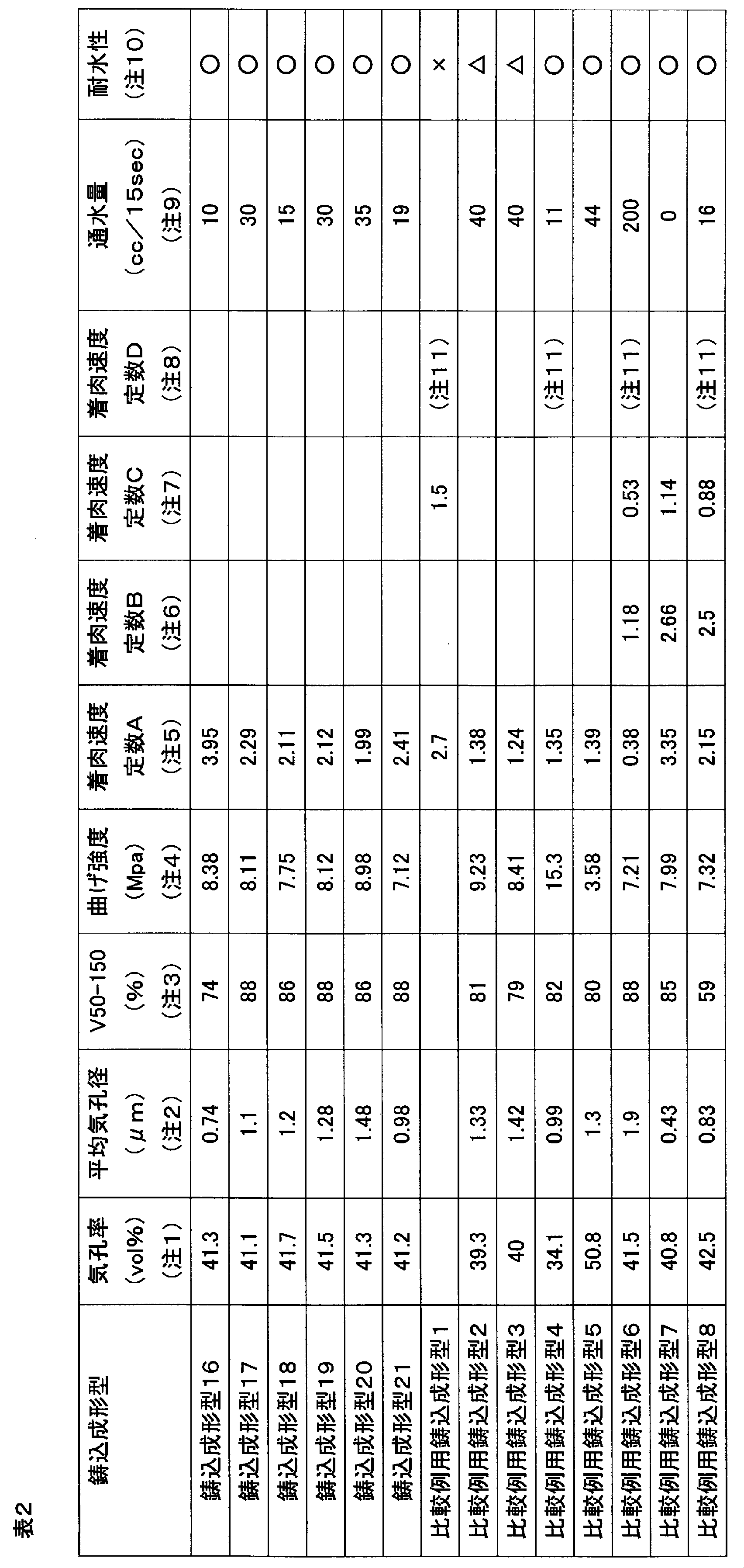
(注1)アルキメデス法により気孔率を測定した。この方法で測定した気孔率は次に述べる水銀圧入式気孔径分布測定装置で求めた気孔率とほぼ一致していた。
(注2)(注3)水銀圧入式気孔径分布測定装置を用いて測定した。測定条件は下記の通りである。
メーカー:MICROMERITICS(マイクロメリテックス)製
機種 :オートポアIII9410(水銀圧入式細孔分析装置)
測定範囲:0.5~30,000psia(0.35kpa~212Mpa)
測定点数:56点
細孔直径:360~0.006μm
(注4)曲げ強度(MPa)は以下の方法にて測定した。
テストピース寸法 10mm×10mm×120mm
3点曲げ
スパン100mm
ヘッドスピード2.5mm/分
テストピースは、30分間真空吸引した後に水没させ、更に30分間真空吸引した状態のものを用いた。
(注5)着肉速度定数A(10‐2mm2/sec)は以下の方法で算出した。
1) 100mmφ×30mmtの鋳込成形型テストピースを飽水率50%となるように調節した。
2) 上記テストピースに60mmφのアクリル管を立て、そのアクリル管中に50mmの深さまで大型衛生陶器用ビトレアスチャイナ泥漿(比重1.8)を流し込んだ。
3) アクリル管の外から観察して見かけ12mm着肉するまで着肉時間t秒放置した後に未着肉の泥漿を排出した。
4) 着肉体の表面に付着した残留泥漿を洗浄して取り除いた。
5) 着肉体の中央部の厚みL(mm)を測定した。
6) 着肉速度定数A=L2/tを求めた。
なお、比較例用鋳込成形型1は、前述の1)で飽水率を50%にコントロールする代わりに石膏型を40℃で24時間乾燥させた以外は同様に算出した。他の泥漿を使用する場合も同様である。
(注6)着肉速度定数B(10‐2mm2/sec)は(注5)の3)において、着肉時間の開始1分後から、着肉時間tの85%まで、つまり0.85×t秒までの間、テストピースを真空吸引した以外は(注5)と同様に算出した。なお真空吸引時において、真空ポンプとテストピースの間の圧力を0.01~0.015MPaとなるようにした。
(注7)着肉速度定数C(10‐2mm2/sec)は(注5)の2)において泥漿として大型製品用高純度アルミナ泥漿(比重2.5)を用いた以外は(注5)と同様に算出した。
(注8)着肉速度定数D(10‐2mm2/sec)は(注5)の2)において泥漿として粉末冶金機械部品用鉄粉泥漿(比重4.2)を用いた以外は(注5)と同様に算出した。
(注9)通水量は以下の方法で測定した。
1 ) 100mmφ×30mmtの鋳込成形型テストピースにおいて、側面から水が出ないように側面を完全にシールした後に完全飽水状態にした。なお、ここで完全飽水状態とは、気孔が全て水で満たされた状態を指す。
2) 一方の端部から0.3MPaの水圧をかけ、水圧をかけはじめてから15秒後までのもう一方の端部から排出される水量を測定した。
(注10)耐水性の評価は、(注5)の1)~3)を繰り返して50回着肉を行い、目視にて型表面の状態を観察し、以下の基準で評価した。
○:型表面に全く変化が認められない。
△:型表面に部分的に凹凸が生じて肌荒れしている。
×:型表面が全体的にボロボロになり、小孔や凹凸が認められる。
(注11)成形体が途中から低充填で柔らかくなり、変形するため厚みを測定することができない。
(注2)(注3)水銀圧入式気孔径分布測定装置を用いて測定した。測定条件は下記の通りである。
メーカー:MICROMERITICS(マイクロメリテックス)製
機種 :オートポアIII9410(水銀圧入式細孔分析装置)
測定範囲:0.5~30,000psia(0.35kpa~212Mpa)
測定点数:56点
細孔直径:360~0.006μm
(注4)曲げ強度(MPa)は以下の方法にて測定した。
テストピース寸法 10mm×10mm×120mm
3点曲げ
スパン100mm
ヘッドスピード2.5mm/分
テストピースは、30分間真空吸引した後に水没させ、更に30分間真空吸引した状態のものを用いた。
(注5)着肉速度定数A(10‐2mm2/sec)は以下の方法で算出した。
1) 100mmφ×30mmtの鋳込成形型テストピースを飽水率50%となるように調節した。
2) 上記テストピースに60mmφのアクリル管を立て、そのアクリル管中に50mmの深さまで大型衛生陶器用ビトレアスチャイナ泥漿(比重1.8)を流し込んだ。
3) アクリル管の外から観察して見かけ12mm着肉するまで着肉時間t秒放置した後に未着肉の泥漿を排出した。
4) 着肉体の表面に付着した残留泥漿を洗浄して取り除いた。
5) 着肉体の中央部の厚みL(mm)を測定した。
6) 着肉速度定数A=L2/tを求めた。
なお、比較例用鋳込成形型1は、前述の1)で飽水率を50%にコントロールする代わりに石膏型を40℃で24時間乾燥させた以外は同様に算出した。他の泥漿を使用する場合も同様である。
(注6)着肉速度定数B(10‐2mm2/sec)は(注5)の3)において、着肉時間の開始1分後から、着肉時間tの85%まで、つまり0.85×t秒までの間、テストピースを真空吸引した以外は(注5)と同様に算出した。なお真空吸引時において、真空ポンプとテストピースの間の圧力を0.01~0.015MPaとなるようにした。
(注7)着肉速度定数C(10‐2mm2/sec)は(注5)の2)において泥漿として大型製品用高純度アルミナ泥漿(比重2.5)を用いた以外は(注5)と同様に算出した。
(注8)着肉速度定数D(10‐2mm2/sec)は(注5)の2)において泥漿として粉末冶金機械部品用鉄粉泥漿(比重4.2)を用いた以外は(注5)と同様に算出した。
(注9)通水量は以下の方法で測定した。
1 ) 100mmφ×30mmtの鋳込成形型テストピースにおいて、側面から水が出ないように側面を完全にシールした後に完全飽水状態にした。なお、ここで完全飽水状態とは、気孔が全て水で満たされた状態を指す。
2) 一方の端部から0.3MPaの水圧をかけ、水圧をかけはじめてから15秒後までのもう一方の端部から排出される水量を測定した。
(注10)耐水性の評価は、(注5)の1)~3)を繰り返して50回着肉を行い、目視にて型表面の状態を観察し、以下の基準で評価した。
○:型表面に全く変化が認められない。
△:型表面に部分的に凹凸が生じて肌荒れしている。
×:型表面が全体的にボロボロになり、小孔や凹凸が認められる。
(注11)成形体が途中から低充填で柔らかくなり、変形するため厚みを測定することができない。
(鋳込成形体の作製1)
鋳込成形型4、鋳込成形型7、比較例用鋳込成形型1、及び比較例用鋳込成形型6の型材で100mmφ×30mmtのテストピースをそれぞれ2枚準備した。2枚のテストピースの間に60mmφ×20mmの塩ビ管を挟み込み、塩ビ管内に泥漿を注型することにより固形鋳込成形を行なった。泥漿は(注5)の大型衛生陶器用ビトレアスチャイナ泥漿および(注7)の大型製品用高純度アルミナ泥漿を用いた。なお塩ビ管の一箇所に孔を開けそこに流し込み用、および60mmのヘッド圧をかけるための流し込み管を立て、ヘッドの減少を測定することにより着肉終了時点を評価した。
鋳込成形型4、鋳込成形型7、比較例用鋳込成形型1、及び比較例用鋳込成形型6の型材で100mmφ×30mmtのテストピースをそれぞれ2枚準備した。2枚のテストピースの間に60mmφ×20mmの塩ビ管を挟み込み、塩ビ管内に泥漿を注型することにより固形鋳込成形を行なった。泥漿は(注5)の大型衛生陶器用ビトレアスチャイナ泥漿および(注7)の大型製品用高純度アルミナ泥漿を用いた。なお塩ビ管の一箇所に孔を開けそこに流し込み用、および60mmのヘッド圧をかけるための流し込み管を立て、ヘッドの減少を測定することにより着肉終了時点を評価した。
鋳込成形型4、鋳込成形型7、比較例用鋳込成形型6においては着肉時間の開始1分後から着肉時間の85%までテストピースを真空吸引した。真空吸引時の圧力は、真空ポンプとテストピースの間の圧力が0.01~0.015MPaとなるようにした。比較例用鋳込成形型1においては、泥漿を流し込む前にテストピースを40℃で24時間乾燥させた。鋳込成形型4、鋳込成形型7、比較例用鋳込成形型6においては、泥漿を流し込む前に飽水率を50%に調整した。塩ビ管の厚みの分の20mm着肉終了後、型を外し、塩ビ管内の成形体を40℃で一晩乾燥させた。その後、塩ビ管より成形体を外し、120℃で12時間乾燥させた。その後20mm厚の鋳込成形体の中央部から20mm*20mmの鋳込成形体を切り出し、実施例1~4、及び比較例1~4の鋳込成形体を得た。各鋳込成形体を5層にスライスして充填率をアルキメデス法で測定した。それぞれの部位を順にA、B、C,D、及びE(A及びEが型に接している部分でCが中央部)として、得られた充填率および得られた充填率の最大値と最小値の差を表3に示す。
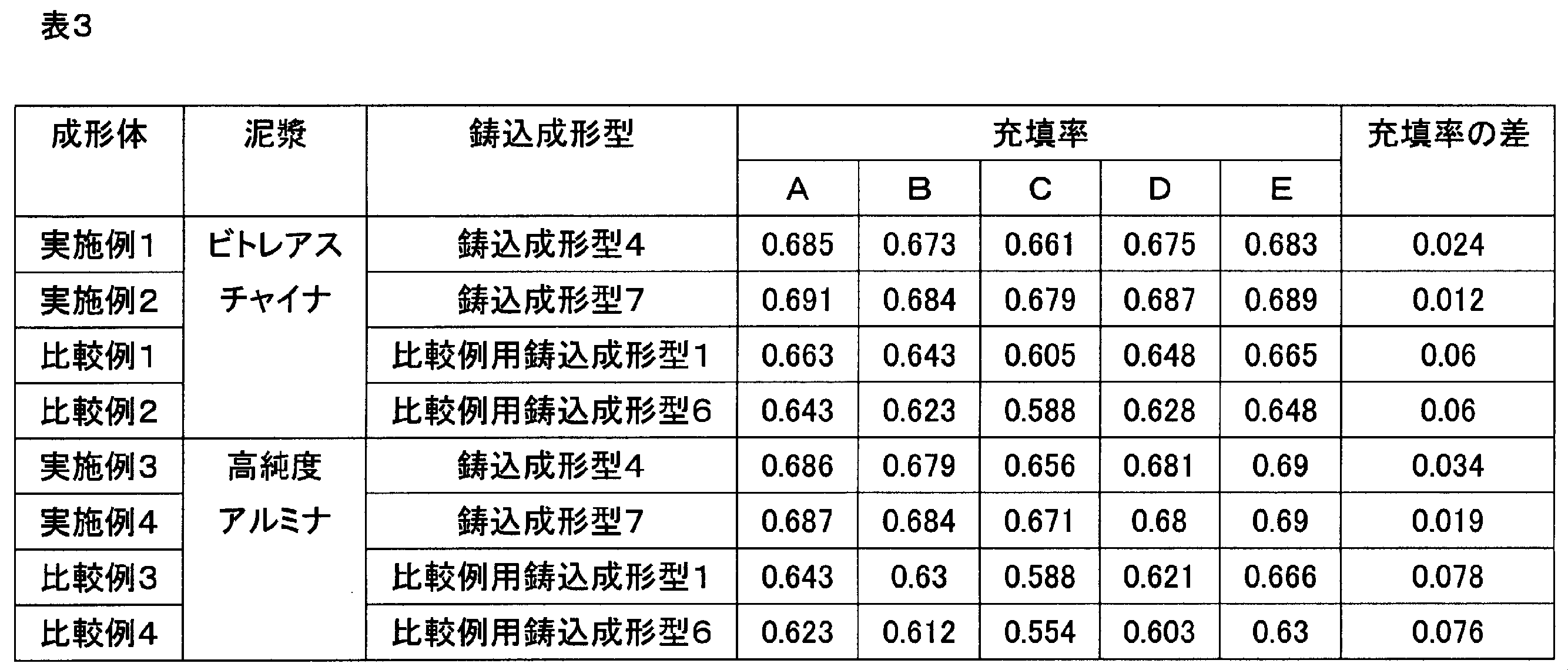
(鋳込成形体の作製2)
鋳込成形型4、鋳込成形型7、比較例用鋳込成形型1、及び比較例用鋳込成形型6の型材で100mmφ×30mmtのテストピースをそれぞれ準備した。鋳込成形型4、鋳込成形型7、比較例用鋳込成形型6においては、泥漿を流し込む前に飽水率を50%に調整した。比較例用鋳込成形型1においては、泥漿を流し込む前にテストピースを40℃で24時間乾燥させた。それぞれのテストピースの上に60mmφのアクリル管を立て、そのアクリル管中に50mmの深さまで泥漿を流し込んだ。泥漿は(注5)の大型衛生陶器用ビトレアスチャイナ泥漿に水を添加して比重を1.77にした泥漿、および(注8)で述べた粉末冶金機械部品用鉄粉泥漿を用いた。アクリル管の外から観察して、それぞれの型の部分に見かけ13mm着肉するまで放置した。その後に未着肉の泥漿を排泥した。
鋳込成形型4、鋳込成形型7、比較例用鋳込成形型1、及び比較例用鋳込成形型6の型材で100mmφ×30mmtのテストピースをそれぞれ準備した。鋳込成形型4、鋳込成形型7、比較例用鋳込成形型6においては、泥漿を流し込む前に飽水率を50%に調整した。比較例用鋳込成形型1においては、泥漿を流し込む前にテストピースを40℃で24時間乾燥させた。それぞれのテストピースの上に60mmφのアクリル管を立て、そのアクリル管中に50mmの深さまで泥漿を流し込んだ。泥漿は(注5)の大型衛生陶器用ビトレアスチャイナ泥漿に水を添加して比重を1.77にした泥漿、および(注8)で述べた粉末冶金機械部品用鉄粉泥漿を用いた。アクリル管の外から観察して、それぞれの型の部分に見かけ13mm着肉するまで放置した。その後に未着肉の泥漿を排泥した。
排泥後、型からアクリル管を外し、アクリル管内の成形体を40℃で一晩乾燥させた。その後、アクリル管より成形体を外し、120℃で12時間乾燥させた。その後鋳込成形体の中央部から20mm*20mmの鋳込成形体を切り出し、この切り出した鋳込成形体の厚みの20%に相当する排泥部分に接する部分を除去し、実施例5~8、及び比較例5~8の鋳込成形体を得た。各鋳込成形体を5層にスライスして充填率をアルキメデス法で測定した。それぞれの部位を順にA、B、C、D、及びE(Aが型に接している部分でEが除去した部分に接する部分)として、得られた充填率および充填率の最大値と最小値の差を表4に示す。
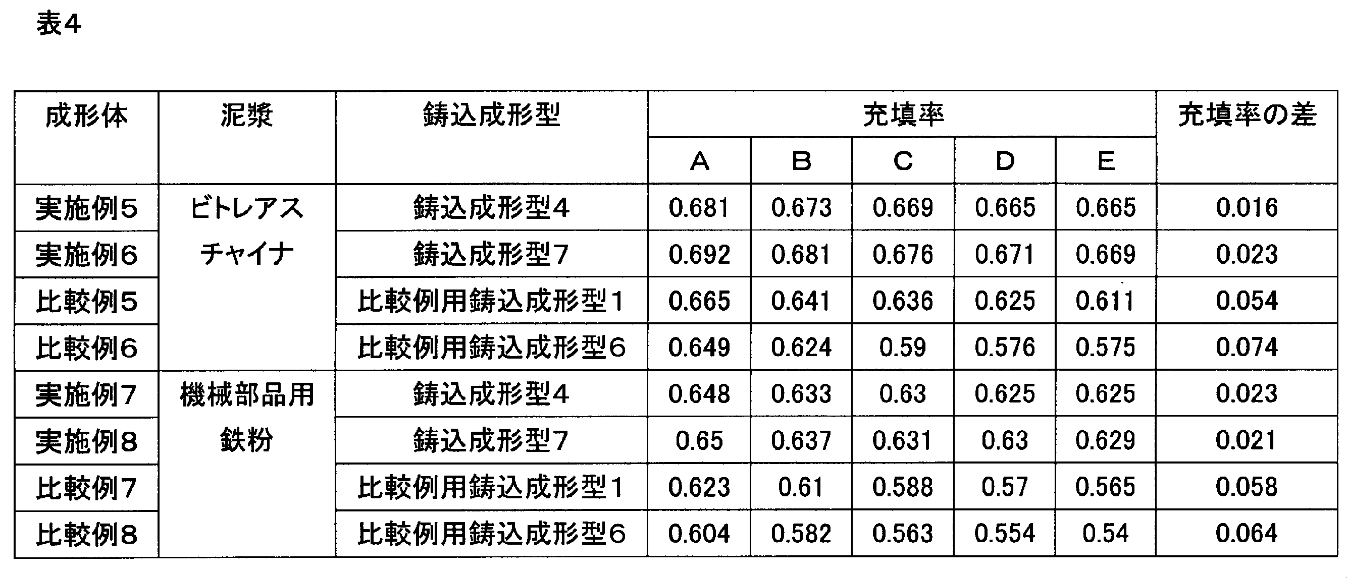
(鋳込成形体の作製3)
鋳込成形型10、鋳込成形型15、鋳込成形型18、及び比較例用鋳込成形型8の型材で100mmφ×30mmtのテストピースをそれぞれ2枚準備した。2枚のテストピースの間に60mmφ*15mmの塩ビ管を挟み込み、塩ビ管内に泥漿を注型することにより固形鋳込成形を行なった。泥漿は高比剛性構造材料用SiC泥漿(比重=1.81)を用いた。なお塩ビ管の一箇所に孔を開けそこに流し込み用、および40mmのヘッド圧をかけるための流し込み管を立て、ヘッドの減少を測定することにより着肉終了時点を評価した。
鋳込成形型10、鋳込成形型15、鋳込成形型18、及び比較例用鋳込成形型8の型材で100mmφ×30mmtのテストピースをそれぞれ2枚準備した。2枚のテストピースの間に60mmφ*15mmの塩ビ管を挟み込み、塩ビ管内に泥漿を注型することにより固形鋳込成形を行なった。泥漿は高比剛性構造材料用SiC泥漿(比重=1.81)を用いた。なお塩ビ管の一箇所に孔を開けそこに流し込み用、および40mmのヘッド圧をかけるための流し込み管を立て、ヘッドの減少を測定することにより着肉終了時点を評価した。
それぞれの鋳込成形型においては着肉時間の開始1分後から着肉時間の85%までテストピースを真空吸引した。真空吸引時の圧力は、真空ポンプとテストピースの間の圧力が0.01~0.015MPaとなるようにした。またそれぞれの鋳込成形型においては、泥漿を流し込む前に飽水率を50%に調整した。塩ビ管の厚みの分の15mm着肉終了後、型を外し、塩ビ管内の成形体を40℃で一晩乾燥させた。その後、塩ビ管より成形体を外し、120℃で12時間乾燥させた。その後15mm厚の鋳込成形体の中央部から20mm*20mmの鋳込成形体を切り出し、実施例9から11の鋳込成形体、及び比較例9の鋳込成形体を得た。各鋳込成形体を5層にスライスして充填率をアルキメデス法で測定した。それぞれの部位を順にA、B、C、D、及びE(A、Eが型に接している部分でCが中央部)として、得られた充填率および充填率の最大値と最小値の差を表5に示す。

(鋳込成形体の作製4)
鋳込成形型1および鋳込成形型7の型材で、100mmφ×30mmtのテストピースを以下の順序で作製した。
鋳込成形型1および鋳込成形型7の型材で、100mmφ×30mmtのテストピースを以下の順序で作製した。
まず、100mmφ×30mmtのテストピース作製用の流し込み型を半月状に中央で間仕切りにより区切り、まず一方に鋳込成形型1の原料である樹脂型スラリーを注型した。その後スラリーに含まれる水が蒸発しないような状態において半硬化状態になった後に間仕切りを外し、もう一方の半月部分に鋳込成形型7の原料である樹脂型スラリーを注型した。 その後スラリーに含まれる水が蒸発しないような状態において含水状態のまま完全硬化させ、硬化後脱型して鋳込成形型のテストピースを得た。
比較用鋳込成形型6および比較用鋳込成形型7の型材により、同様の方法にて100mmφ×30mmtのテストピースを作製した。
得られたそれぞれのテストピースに60mmφのアクリル管を立て、そのアクリル管中に50mmの深さまで(注5)の大型衛生陶器用ビトレアスチャイナ泥漿を流し込んだ。アクリル管の外から観察して、鋳込成形型7の部分および比較例鋳込成形型7の部分に見かけ15mm着肉するまで放置した。その後に未着肉の泥漿を排泥し、土締め・脱型・乾燥を経て鋳込成形体を得た。また、得られた鋳込成形体を最高温度1180℃の通常の衛生陶器用焼成温度で焼成し、焼成体を得た。
鋳込成形型1および鋳込成形型7のテストピースで成形した鋳込成形体にはクラックや欠陥が一切なかった。鋳込成形体の各部分の充填率を測定したところ、鋳込成形型1の部分では0.649、鋳込成形型7の型の部分では0.67であった。焼成終了後の焼成体にはクラックや欠陥は全くなかった。それぞれの部分の厚み比は鋳込成形型1の部分:鋳込成形型7の部分=約1:4であり、その境界部分はなだらかなRを持つ切り立った形状であった。
これに対し、比較用鋳込成形型6および比較用鋳込成形型7のテストピースで成形した鋳込成形体は、型の接合面にクラックが発生して変形しており、正確に厚みを測定することはできなかった。鋳込成形体の各部分の充填率を測定したところ、比較用鋳込成形型6の部分では0.613、比較用鋳込成形型7の部分では0.668であった。
(鋳込成形体の作製5)
鋳込成形型1および鋳込成形型7の型材を用いて200mm×200mmの板状の鋳込成形体を成形するための固形鋳込成形型を作製した。
鋳込成形型1および鋳込成形型7の型材を用いて200mm×200mmの板状の鋳込成形体を成形するための固形鋳込成形型を作製した。
板状成形体の厚みは、鋳込成形型1の部分は5mm、鋳込成形型7の部分は25mmとし、中央を境界として厚みが異なるようにした。厚みが異なる境界の段差部分は約1.5mmRとなるようにした。
比較例用鋳込成形型1の型材を用いて200mm×200mmの板状の鋳込成形体を成形するための固形鋳込成形石膏型を作製した。
板状成形体の厚みは、中央を境界として厚みが異なるようにし、半分は10mm、もう半分は12.5mmとなるようにした。厚みが異なる部分の境界は約1.5mmRとなるようにした。
得られたそれぞれの固形鋳込成形型に(注5)の大型衛生陶器用ビトレアスチャイナ泥漿を流し込んで鋳込成形体を得た。
その結果、鋳込成形型1および鋳込成形型7の固形鋳込成形型を用いて得られた鋳込成形体にはクラックや欠陥が一切無かった。比較例用鋳込成形型1の固形鋳込成形型を用いて得られた鋳込成形体は、厚肉部分が柔らかく脱型時に変形を生じた。
(鋳込成形体の作製6)
図4に示すリブ構造成形体を製作するための鋳込成形型を、吸水層として鋳込成形型4、鋳込成形型7、比較例用鋳込成形型1、及び比較例用鋳込成形型6の型材を用いてそれぞれ作製した。なお鋳込成形型4、鋳込成形型7、及び比較例用鋳込成形型6は上下二つ割でリブ部は上型と一体構造とし、比較例用鋳込成形型1の型は上下、側面2ヶ、リブ4ヶの八つ割り型とした。脱型方法は鋳込成形型4、鋳込成形型7、及び比較例用鋳込成形型6は各割型に加圧エアー供給手段より背圧をかける水膜脱型であり、比較例用鋳込成形型1はリブ部のみ石膏割型にエアー注入とした。
図4に示すリブ構造成形体を製作するための鋳込成形型を、吸水層として鋳込成形型4、鋳込成形型7、比較例用鋳込成形型1、及び比較例用鋳込成形型6の型材を用いてそれぞれ作製した。なお鋳込成形型4、鋳込成形型7、及び比較例用鋳込成形型6は上下二つ割でリブ部は上型と一体構造とし、比較例用鋳込成形型1の型は上下、側面2ヶ、リブ4ヶの八つ割り型とした。脱型方法は鋳込成形型4、鋳込成形型7、及び比較例用鋳込成形型6は各割型に加圧エアー供給手段より背圧をかける水膜脱型であり、比較例用鋳込成形型1はリブ部のみ石膏割型にエアー注入とした。
それぞれの型に(注7)の大型製品用高純度アルミナ泥漿を用いて固形鋳込成形を行なった。着肉終了後、土締め時間として10分、30分、2時間、24時間、及び72時間の5条件で放置時間をとり、この後に脱型した。なお吸水層は着肉時間及び土締め時間において大気開放させた。その結果は比較例用鋳込成形型1ではあらゆる土締め条件でコーナーR部ほぼ全ての部分で締り切れが発生し、また土締め10分の条件では素地が柔らかく脱型時に変形が発生した。また比較例用鋳込成形型6では土締め10分の条件でのみコーナーR部に締り切れが発生していなかったが素地が柔らかいため脱型時に変形が生じ、その他の土締め条件ではコーナーR部ほぼ全ての部分で締り切れが発生していた。これに対して鋳込成形型4および鋳込成形型7ではあらゆる土締め条件で全く切れが発生しておらず、又脱型時に変形も生じなかった。そして鋳込成形型4および鋳込成形型7で得られた成形体を乾燥・焼成したが特に欠点は発生しなかった。なお鋳込成形型4を用い土締め時間10分の条件で、着肉時間の最後の30分と土締め時間10分の計40分間大気開放をしなかった場合には素地が柔らかく脱型時に変形が発生した。
(鋳込成形体の作製7)
外形のサイズは300mm×300mm×80mmであり、成形時には縦方向(重力方向)のサイズが80mmとなるように型が載置され、一重部と二重部の両方を持ち、二重部の厚みは10mmであり、一重部の排泥空間の縦方向(重力方向)の最大厚みは一重部の厚みが8mmのとき64mmである成形体を成形するための鋳込成形型の吸水層を、鋳込成形型4及び比較例用鋳込成形型1の型材を用いてそれぞれ作製した。続いてそれぞれの型に(注5)の大型衛生陶器用ビトレアスチャイナ泥漿に水を添加して比重を1.74にした泥漿を用いて成形体を作製した。
外形のサイズは300mm×300mm×80mmであり、成形時には縦方向(重力方向)のサイズが80mmとなるように型が載置され、一重部と二重部の両方を持ち、二重部の厚みは10mmであり、一重部の排泥空間の縦方向(重力方向)の最大厚みは一重部の厚みが8mmのとき64mmである成形体を成形するための鋳込成形型の吸水層を、鋳込成形型4及び比較例用鋳込成形型1の型材を用いてそれぞれ作製した。続いてそれぞれの型に(注5)の大型衛生陶器用ビトレアスチャイナ泥漿に水を添加して比重を1.74にした泥漿を用いて成形体を作製した。
比較例用鋳込成形型1を用いて、一重部が8mm厚となるまで着肉させた後に排泥を行なった。続いて土締め条件として排泥空間に投入するエアー圧とエアー圧をかける時間を様々にコントロールして土締めを行なったが、脱型時に成形体の変形が発生しない条件においては締り切れの発生を防止する土締め条件は見つからなかった。
また鋳込成形型4を用いて、一重部が8mmとなるまで着肉させた後に排泥を行なった。続いて土締め条件としてエアー圧とエアー圧をかける時間を様々にコントロールして脱型時に成形体の変形が発生しない条件で土締めを行った後に脱型した。脱型直後の成形体の二重部の一重部から5mmはなれた部分より10mm×10mmの成形体を切り出し5層にスライスして充填率の測定を行なった。なおそれぞれの部位を順にA、B、C、D、E(A、Eが型に接している部分でÅが上である)と表示するものとする。また同じ成形試験を二重部の着肉終了時点まで行いその後排泥して同様に充填率を測定した。それぞれの土締め条件における各成形体の土締め時の充填率分布の変化と成形体の締り切れの発生状況を表6に示す。
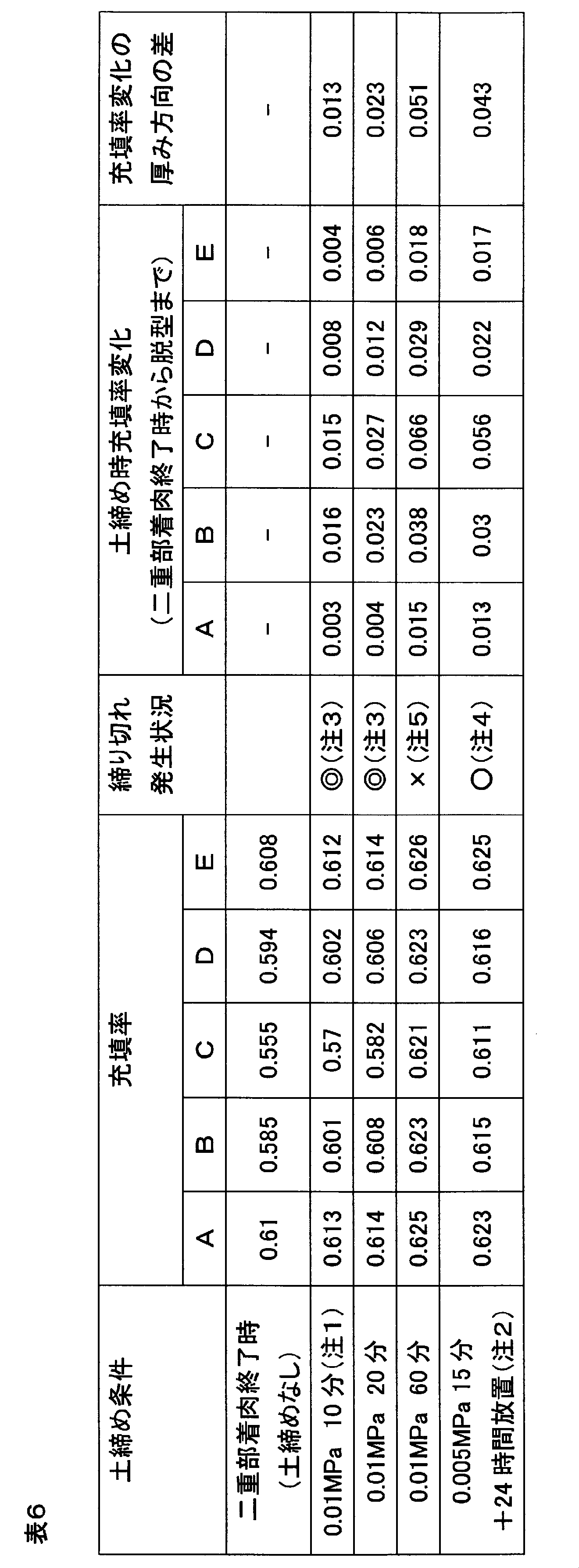
(注1)エアー圧(大気圧と比較してプラスされている圧力)とそのエアー圧をかける時間を表示する。その他のセルにおける表示も同様である。
(注2)注1に例示された土締め条件(この場合は0.005MPaで15分)で土締めした後に、排泥空間を大気圧下の状態に戻し、その後この条件(この場合は24時間)で型内に放置したことを示す。
(注3)◎とは全く締り切れが発生しなかったことを示す。
(注4)○とは締り切れは発生しなかったが、一重部と二重部の境から二重部にかけてごく小さな切れが発生したことを示す。
(注5)×とは二重部に締り切れが発生したことを示す。
(注2)注1に例示された土締め条件(この場合は0.005MPaで15分)で土締めした後に、排泥空間を大気圧下の状態に戻し、その後この条件(この場合は24時間)で型内に放置したことを示す。
(注3)◎とは全く締り切れが発生しなかったことを示す。
(注4)○とは締り切れは発生しなかったが、一重部と二重部の境から二重部にかけてごく小さな切れが発生したことを示す。
(注5)×とは二重部に締り切れが発生したことを示す。
本発明によれば、充填率が均一な鋳込成形体を歩留良く製造することができる。また部分的に厚みが異なる鋳込成形体の製造方法を提供することができる。
1:低着肉型吸水層
2:高着肉型吸水層
3:鋳込成形体
4:不透水型枠
2:高着肉型吸水層
3:鋳込成形体
4:不透水型枠
Claims (18)
- セラミックス粉体または金属粉体の鋳込成形体であって、その厚み方向の充填率の差が0.05以下であることを特徴とする鋳込成形体。
- 前記鋳込成形体が自己吸水性を持ち実質的に耐水性を有する吸水層を備えた鋳込成形型によって製造されたものであることを特徴とする請求項1に記載の鋳込成形体。
- 請求項1または2に記載の鋳込成形体を焼成して製造することを特徴とする焼結体。
- 部分的に厚みが異なるセラミックス粉体または金属粉体の鋳込成形体であって、その隣り合う厚肉部分の厚みと薄肉部分の厚みの比率が1.25倍以上5倍以下であることを特徴とする鋳込成形体。
- 前記鋳込成形体は、第1の厚さを有する第1部分と、前記第1の厚さよりも厚い第2の厚さを有する第2部分と、を有し、
前記第1部分における充填率と前記第2部分における充填率との差が0.05以下である、請求項4記載の鋳込成形体。 - 前記鋳込成形体が自己吸水性を持ち実質的に耐水性を有する吸水層を備えた鋳込成形型によって製造されたものであり、その厚みの差が吸水層各部分の着肉速度の差によって得られたものであることを特徴とする請求項4に記載の鋳込成形体。
- 前記吸水層各部分の着肉速度の差が該吸水層各部分の毛管吸引力の差によって発現したものであることを特徴とする請求項4~6のいずれか1項に記載の鋳込成形体。
- 前記鋳込成形型を形成する吸水層各部分が、複数の割型として構成されており、前記複数の割型の吸水層は着肉速度が異なるものであることを特徴とする請求項4~7のいずれか1項に記載の鋳込成形体。
- 前記鋳込成形型は、複数の吸水層が一体化した吸水層を備えており、
前記複数の吸水層は、着肉速度が異なるものであることを特徴とする請求項4~7のいずれか1項に記載の鋳込成形体。 - 部分的に厚みが異なるセラミックス粉体または金属粉体の鋳込成形体の焼結体であって、その隣り合う厚肉部分の厚みと薄肉部分の厚みの比率が1.25倍以上5倍以下、さらに好ましくは1.5倍以上5倍以下であることを特徴とする焼結体。
- 請求項1、2、及び4~9のいずれか1項に記載の鋳込成形体若しくは請求項3または10に記載の焼結体を製造する製造方法であって、以下の(1)~(4)の工程がこの順序で行われることを特徴とする鋳込成形体または焼成体の製造方法。
(1)自己吸水性を持ち実質的に耐水性を有する吸水層の飽水率を制御する工程
(2)鋳込成形型内に泥漿を注型する工程
(3)泥漿を吸水層に着肉させて成型体を形成する工程
(4)前記成形体を脱型する工程 - 前記(3)泥漿を鋳込成形型に着肉させる工程において、泥漿に直接加圧を行わない事を特徴とする請求項11に記載の製造方法。
- 前記(3)泥漿を鋳込成形型に着肉させる工程において、吸水層が大気開放された状態であることを特徴とする請求項11または12に記載の製造方法。
- 前記(3)泥漿を鋳込成形型に着肉させる工程と前記(4)前記成形体を脱型する工程との間に土締め工程を設け、該土締め工程において二重部分の充填率の着肉終了時から脱型時までの変化の厚み方向の差を0.05以下とする事を特徴とする請求項11~13のいずれか1項に記載の製造方法。
- 自己吸水性を持ち実質的に耐水性を有する吸水層を備えた鋳込成形型であって、該吸水層は、気孔率が35vol%以上50vol%以下であり、平均気孔径が0.5μm以上1.8μm以下であり、前記平均気孔径の50%の粒径から150%の粒径までの累積気孔体積が全気孔体積の60%以上である連続気孔多孔体であることを特徴とする鋳込成形型。
- 前記吸水層に、(1)加圧水供給、(2)加圧エアー供給、(3)真空吸引、4)大気開放のいずれかの切り替え可能な操作を行なう手段を設けた、請求項15に記載の鋳込成形型。
- 前記鋳込成形型は、請求項1、2、及び4~9のいずれか1項に記載の鋳込成形体若しくは請求項3または10に記載の焼結体を製造するためのものである、請求項15または16に記載の鋳込成形型。
- セラミックス粉体または金属粉体の鋳込成形設備であって、請求項11~14のいずれか1項に記載の鋳込成形体の製造方法の各工程を遂行できる成形機と請求項15~17のいずれか1項に記載の鋳込成形型を備えた鋳込成形設備。
Priority Applications (1)
| Application Number | Priority Date | Filing Date | Title |
|---|---|---|---|
| JP2016570725A JPWO2016117688A1 (ja) | 2015-01-23 | 2016-01-22 | 鋳込成形体とその製造方法 |
Applications Claiming Priority (2)
| Application Number | Priority Date | Filing Date | Title |
|---|---|---|---|
| JP2015011537 | 2015-01-23 | ||
| JP2015-011537 | 2015-01-23 |
Publications (1)
| Publication Number | Publication Date |
|---|---|
| WO2016117688A1 true WO2016117688A1 (ja) | 2016-07-28 |
Family
ID=56417218
Family Applications (1)
| Application Number | Title | Priority Date | Filing Date |
|---|---|---|---|
| PCT/JP2016/051872 Ceased WO2016117688A1 (ja) | 2015-01-23 | 2016-01-22 | 鋳込成形体とその製造方法 |
Country Status (3)
| Country | Link |
|---|---|
| JP (1) | JPWO2016117688A1 (ja) |
| TW (1) | TW201702038A (ja) |
| WO (1) | WO2016117688A1 (ja) |
Families Citing this family (1)
| Publication number | Priority date | Publication date | Assignee | Title |
|---|---|---|---|---|
| CN112976231B (zh) * | 2021-03-16 | 2022-09-13 | 长葛市白特瓷业有限公司 | 一种陶瓷卫浴注浆成型工艺及智能设备 |
Citations (10)
| Publication number | Priority date | Publication date | Assignee | Title |
|---|---|---|---|---|
| JPS6375044A (ja) * | 1986-09-17 | 1988-04-05 | Toto Ltd | 連続気孔多孔体の製造方法 |
| JPH01186303A (ja) * | 1988-01-21 | 1989-07-25 | Toyota Motor Corp | 鋳込成形法 |
| JPH04270602A (ja) * | 1991-02-26 | 1992-09-28 | Ngk Insulators Ltd | 高圧鋳込み成形型及びそれを用いた成形方法 |
| JPH05228913A (ja) * | 1991-07-26 | 1993-09-07 | Sumitomo Electric Ind Ltd | セラミックスの成形法および装置 |
| JPH06285825A (ja) * | 1993-04-06 | 1994-10-11 | Denki Kagaku Kogyo Kk | 型材及び成形型の製造法 |
| JPH0929717A (ja) * | 1995-07-20 | 1997-02-04 | Sumitomo Electric Ind Ltd | セラミックスの成形法 |
| WO1997007948A1 (en) * | 1995-08-26 | 1997-03-06 | Toto Ltd. | Method of slip casting of powders, casting mold used in said method, and process for producing open-cell porous body used in said mold |
| JPH10138218A (ja) * | 1996-11-06 | 1998-05-26 | Toto Ltd | 加圧鋳込み成形型及び同型を用いた加圧鋳込み成形方法 |
| JP2000061917A (ja) * | 1998-08-24 | 2000-02-29 | Mitsui Mining & Smelting Co Ltd | Ito成形体およびその製造方法並びにito焼結体の製造方法 |
| JP2002225014A (ja) * | 2001-01-31 | 2002-08-14 | Toto Ltd | 鋳込成形用型及びその製造方法 |
-
2016
- 2016-01-22 WO PCT/JP2016/051872 patent/WO2016117688A1/ja not_active Ceased
- 2016-01-22 JP JP2016570725A patent/JPWO2016117688A1/ja active Pending
- 2016-01-22 TW TW105102045A patent/TW201702038A/zh unknown
Patent Citations (10)
| Publication number | Priority date | Publication date | Assignee | Title |
|---|---|---|---|---|
| JPS6375044A (ja) * | 1986-09-17 | 1988-04-05 | Toto Ltd | 連続気孔多孔体の製造方法 |
| JPH01186303A (ja) * | 1988-01-21 | 1989-07-25 | Toyota Motor Corp | 鋳込成形法 |
| JPH04270602A (ja) * | 1991-02-26 | 1992-09-28 | Ngk Insulators Ltd | 高圧鋳込み成形型及びそれを用いた成形方法 |
| JPH05228913A (ja) * | 1991-07-26 | 1993-09-07 | Sumitomo Electric Ind Ltd | セラミックスの成形法および装置 |
| JPH06285825A (ja) * | 1993-04-06 | 1994-10-11 | Denki Kagaku Kogyo Kk | 型材及び成形型の製造法 |
| JPH0929717A (ja) * | 1995-07-20 | 1997-02-04 | Sumitomo Electric Ind Ltd | セラミックスの成形法 |
| WO1997007948A1 (en) * | 1995-08-26 | 1997-03-06 | Toto Ltd. | Method of slip casting of powders, casting mold used in said method, and process for producing open-cell porous body used in said mold |
| JPH10138218A (ja) * | 1996-11-06 | 1998-05-26 | Toto Ltd | 加圧鋳込み成形型及び同型を用いた加圧鋳込み成形方法 |
| JP2000061917A (ja) * | 1998-08-24 | 2000-02-29 | Mitsui Mining & Smelting Co Ltd | Ito成形体およびその製造方法並びにito焼結体の製造方法 |
| JP2002225014A (ja) * | 2001-01-31 | 2002-08-14 | Toto Ltd | 鋳込成形用型及びその製造方法 |
Also Published As
| Publication number | Publication date |
|---|---|
| TW201702038A (zh) | 2017-01-16 |
| JPWO2016117688A1 (ja) | 2017-12-07 |
Similar Documents
| Publication | Publication Date | Title |
|---|---|---|
| US3431332A (en) | Ceramic casting techniques | |
| NO170821B (no) | Fremgangsmaate for tett sammenfoeyning av en hylse og et undervanns roer paa stor dybde | |
| JPH05330894A (ja) | 陶磁器の鋳込み成形方法、及びトラップ部を有する衛生陶器の成形方法 | |
| JPWO1997007948A1 (ja) | 粉体の鋳込成形方法及び鋳込成形に用いられる鋳込成形型、及び鋳込成形型に用いられる連続気孔多孔体の製造方法 | |
| EP1063005A2 (en) | Ceramic membrane | |
| CN109692943B (zh) | 一种真空压力浸渗正压法制备SiC3D/Al复合材料的方法 | |
| US8168113B2 (en) | Method for the production of a ceramic molded part | |
| WO2016117688A1 (ja) | 鋳込成形体とその製造方法 | |
| JP2851293B2 (ja) | 鋳物砂からの鋳型製造用不均質多孔性型具及びその製造方法 | |
| CN108145832B (zh) | 一种高强、高透水混凝土的成型方法 | |
| DE962595C (de) | Giessform fuer Formkoerper, insbesondere aus keramischem Rohmaterial | |
| CN204019702U (zh) | 制备石英坩埚的模具 | |
| EP0210027B1 (en) | Method for forming cast article by slip casting | |
| US20120001360A1 (en) | Concrete block mold with diamond insert | |
| CN104128988B (zh) | 制备石英坩埚的模具及工艺 | |
| JP2012071547A (ja) | セラミックス製品の製造方法、及びセラミックス成形用鋳型 | |
| JP3155660B2 (ja) | セラミック製鋳込成形型の製造方法 | |
| CN206597907U (zh) | 一种用于制备预制式浇注上水口的模具 | |
| CN121607566B (zh) | 一种熔模铸造用型壳层浆料及真空浸浆工艺方法 | |
| JPH01269505A (ja) | 有底成形体の鋳込成形方法及び成形鋳込型 | |
| JP6066827B2 (ja) | セラミックス成形体の製造装置および製造方法 | |
| JPH11291213A (ja) | 不定形耐火ブロックの形成方法 | |
| JPH01304902A (ja) | セラミックスの成形方法及び成形装置 | |
| JP2863085B2 (ja) | 鋳込成形型及び鋳込成形方法 | |
| JP6987578B2 (ja) | ポーラス・スプリットン・ブロック |
Legal Events
| Date | Code | Title | Description |
|---|---|---|---|
| 121 | Ep: the epo has been informed by wipo that ep was designated in this application |
Ref document number: 16740295 Country of ref document: EP Kind code of ref document: A1 |
|
| ENP | Entry into the national phase |
Ref document number: 2016570725 Country of ref document: JP Kind code of ref document: A |
|
| NENP | Non-entry into the national phase |
Ref country code: DE |
|
| 122 | Ep: pct application non-entry in european phase |
Ref document number: 16740295 Country of ref document: EP Kind code of ref document: A1 |