WO2016117353A1 - 伝達装置 - Google Patents
伝達装置 Download PDFInfo
- Publication number
- WO2016117353A1 WO2016117353A1 PCT/JP2016/050198 JP2016050198W WO2016117353A1 WO 2016117353 A1 WO2016117353 A1 WO 2016117353A1 JP 2016050198 W JP2016050198 W JP 2016050198W WO 2016117353 A1 WO2016117353 A1 WO 2016117353A1
- Authority
- WO
- WIPO (PCT)
- Prior art keywords
- suction port
- oil
- hydraulic pressure
- suction
- oil passage
- Prior art date
- Legal status (The legal status is an assumption and is not a legal conclusion. Google has not performed a legal analysis and makes no representation as to the accuracy of the status listed.)
- Ceased
Links
Images


Classifications
-
- F—MECHANICAL ENGINEERING; LIGHTING; HEATING; WEAPONS; BLASTING
- F04—POSITIVE - DISPLACEMENT MACHINES FOR LIQUIDS; PUMPS FOR LIQUIDS OR ELASTIC FLUIDS
- F04C—ROTARY-PISTON, OR OSCILLATING-PISTON, POSITIVE-DISPLACEMENT MACHINES FOR LIQUIDS; ROTARY-PISTON, OR OSCILLATING-PISTON, POSITIVE-DISPLACEMENT PUMPS
- F04C2/00—Rotary-piston machines or pumps
- F04C2/30—Rotary-piston machines or pumps having the characteristics covered by two or more groups F04C2/02, F04C2/08, F04C2/22, F04C2/24 or having the characteristics covered by one of these groups together with some other type of movement between co-operating members
- F04C2/34—Rotary-piston machines or pumps having the characteristics covered by two or more groups F04C2/02, F04C2/08, F04C2/22, F04C2/24 or having the characteristics covered by one of these groups together with some other type of movement between co-operating members having the movement defined in groups F04C2/08 or F04C2/22 and relative reciprocation between the co-operating members
- F04C2/344—Rotary-piston machines or pumps having the characteristics covered by two or more groups F04C2/02, F04C2/08, F04C2/22, F04C2/24 or having the characteristics covered by one of these groups together with some other type of movement between co-operating members having the movement defined in groups F04C2/08 or F04C2/22 and relative reciprocation between the co-operating members with vanes reciprocating with respect to the inner member
- F04C2/3446—Rotary-piston machines or pumps having the characteristics covered by two or more groups F04C2/02, F04C2/08, F04C2/22, F04C2/24 or having the characteristics covered by one of these groups together with some other type of movement between co-operating members having the movement defined in groups F04C2/08 or F04C2/22 and relative reciprocation between the co-operating members with vanes reciprocating with respect to the inner member the inner and outer member being in contact along more than one line or surface
-
- F—MECHANICAL ENGINEERING; LIGHTING; HEATING; WEAPONS; BLASTING
- F04—POSITIVE - DISPLACEMENT MACHINES FOR LIQUIDS; PUMPS FOR LIQUIDS OR ELASTIC FLUIDS
- F04C—ROTARY-PISTON, OR OSCILLATING-PISTON, POSITIVE-DISPLACEMENT MACHINES FOR LIQUIDS; ROTARY-PISTON, OR OSCILLATING-PISTON, POSITIVE-DISPLACEMENT PUMPS
- F04C2/00—Rotary-piston machines or pumps
- F04C2/30—Rotary-piston machines or pumps having the characteristics covered by two or more groups F04C2/02, F04C2/08, F04C2/22, F04C2/24 or having the characteristics covered by one of these groups together with some other type of movement between co-operating members
- F04C2/34—Rotary-piston machines or pumps having the characteristics covered by two or more groups F04C2/02, F04C2/08, F04C2/22, F04C2/24 or having the characteristics covered by one of these groups together with some other type of movement between co-operating members having the movement defined in groups F04C2/08 or F04C2/22 and relative reciprocation between the co-operating members
- F04C2/344—Rotary-piston machines or pumps having the characteristics covered by two or more groups F04C2/02, F04C2/08, F04C2/22, F04C2/24 or having the characteristics covered by one of these groups together with some other type of movement between co-operating members having the movement defined in groups F04C2/08 or F04C2/22 and relative reciprocation between the co-operating members with vanes reciprocating with respect to the inner member
-
- F—MECHANICAL ENGINEERING; LIGHTING; HEATING; WEAPONS; BLASTING
- F01—MACHINES OR ENGINES IN GENERAL; ENGINE PLANTS IN GENERAL; STEAM ENGINES
- F01C—ROTARY-PISTON OR OSCILLATING-PISTON MACHINES OR ENGINES
- F01C21/00—Component parts, details or accessories not provided for in groups F01C1/00 - F01C20/00
- F01C21/08—Rotary pistons
- F01C21/0809—Construction of vanes or vane holders
- F01C21/0818—Vane tracking; control therefor
- F01C21/0854—Vane tracking; control therefor by fluid means
- F01C21/0863—Vane tracking; control therefor by fluid means the fluid being the working fluid
-
- F—MECHANICAL ENGINEERING; LIGHTING; HEATING; WEAPONS; BLASTING
- F01—MACHINES OR ENGINES IN GENERAL; ENGINE PLANTS IN GENERAL; STEAM ENGINES
- F01C—ROTARY-PISTON OR OSCILLATING-PISTON MACHINES OR ENGINES
- F01C21/00—Component parts, details or accessories not provided for in groups F01C1/00 - F01C20/00
- F01C21/10—Outer members for co-operation with rotary pistons; Casings
- F01C21/104—Stators; Members defining the outer boundaries of the working chamber
- F01C21/108—Stators; Members defining the outer boundaries of the working chamber with an axial surface, e.g. side plates
-
- F—MECHANICAL ENGINEERING; LIGHTING; HEATING; WEAPONS; BLASTING
- F04—POSITIVE - DISPLACEMENT MACHINES FOR LIQUIDS; PUMPS FOR LIQUIDS OR ELASTIC FLUIDS
- F04C—ROTARY-PISTON, OR OSCILLATING-PISTON, POSITIVE-DISPLACEMENT MACHINES FOR LIQUIDS; ROTARY-PISTON, OR OSCILLATING-PISTON, POSITIVE-DISPLACEMENT PUMPS
- F04C11/00—Combinations of two or more machines or pumps, each being of rotary-piston or oscillating-piston type; Pumping installations
-
- F—MECHANICAL ENGINEERING; LIGHTING; HEATING; WEAPONS; BLASTING
- F04—POSITIVE - DISPLACEMENT MACHINES FOR LIQUIDS; PUMPS FOR LIQUIDS OR ELASTIC FLUIDS
- F04C—ROTARY-PISTON, OR OSCILLATING-PISTON, POSITIVE-DISPLACEMENT MACHINES FOR LIQUIDS; ROTARY-PISTON, OR OSCILLATING-PISTON, POSITIVE-DISPLACEMENT PUMPS
- F04C11/00—Combinations of two or more machines or pumps, each being of rotary-piston or oscillating-piston type; Pumping installations
- F04C11/001—Combinations of two or more machines or pumps, each being of rotary-piston or oscillating-piston type; Pumping installations of similar working principle
- F04C11/003—Combinations of two or more machines or pumps, each being of rotary-piston or oscillating-piston type; Pumping installations of similar working principle having complementary function
-
- F—MECHANICAL ENGINEERING; LIGHTING; HEATING; WEAPONS; BLASTING
- F04—POSITIVE - DISPLACEMENT MACHINES FOR LIQUIDS; PUMPS FOR LIQUIDS OR ELASTIC FLUIDS
- F04C—ROTARY-PISTON, OR OSCILLATING-PISTON, POSITIVE-DISPLACEMENT MACHINES FOR LIQUIDS; ROTARY-PISTON, OR OSCILLATING-PISTON, POSITIVE-DISPLACEMENT PUMPS
- F04C14/00—Control of, monitoring of, or safety arrangements for, machines, pumps or pumping installations
- F04C14/02—Control of, monitoring of, or safety arrangements for, machines, pumps or pumping installations specially adapted for several machines or pumps connected in series or in parallel
-
- F—MECHANICAL ENGINEERING; LIGHTING; HEATING; WEAPONS; BLASTING
- F04—POSITIVE - DISPLACEMENT MACHINES FOR LIQUIDS; PUMPS FOR LIQUIDS OR ELASTIC FLUIDS
- F04C—ROTARY-PISTON, OR OSCILLATING-PISTON, POSITIVE-DISPLACEMENT MACHINES FOR LIQUIDS; ROTARY-PISTON, OR OSCILLATING-PISTON, POSITIVE-DISPLACEMENT PUMPS
- F04C14/00—Control of, monitoring of, or safety arrangements for, machines, pumps or pumping installations
- F04C14/06—Control of, monitoring of, or safety arrangements for, machines, pumps or pumping installations specially adapted for stopping, starting, idling or no-load operation
- F04C14/065—Capacity control using a multiplicity of units or pumping capacities, e.g. multiple chambers, individually switchable or controllable
-
- F—MECHANICAL ENGINEERING; LIGHTING; HEATING; WEAPONS; BLASTING
- F04—POSITIVE - DISPLACEMENT MACHINES FOR LIQUIDS; PUMPS FOR LIQUIDS OR ELASTIC FLUIDS
- F04C—ROTARY-PISTON, OR OSCILLATING-PISTON, POSITIVE-DISPLACEMENT MACHINES FOR LIQUIDS; ROTARY-PISTON, OR OSCILLATING-PISTON, POSITIVE-DISPLACEMENT PUMPS
- F04C14/00—Control of, monitoring of, or safety arrangements for, machines, pumps or pumping installations
- F04C14/24—Control of, monitoring of, or safety arrangements for, machines, pumps or pumping installations characterised by using valves controlling pressure or flow rate, e.g. discharge valves or unloading valves
- F04C14/26—Control of, monitoring of, or safety arrangements for, machines, pumps or pumping installations characterised by using valves controlling pressure or flow rate, e.g. discharge valves or unloading valves using bypass channels
-
- F—MECHANICAL ENGINEERING; LIGHTING; HEATING; WEAPONS; BLASTING
- F04—POSITIVE - DISPLACEMENT MACHINES FOR LIQUIDS; PUMPS FOR LIQUIDS OR ELASTIC FLUIDS
- F04C—ROTARY-PISTON, OR OSCILLATING-PISTON, POSITIVE-DISPLACEMENT MACHINES FOR LIQUIDS; ROTARY-PISTON, OR OSCILLATING-PISTON, POSITIVE-DISPLACEMENT PUMPS
- F04C15/00—Component parts, details or accessories of machines, pumps or pumping installations, not provided for in groups F04C2/00 - F04C14/00
- F04C15/06—Arrangements for admission or discharge of the working fluid, e.g. constructional features of the inlet or outlet
- F04C15/064—Arrangements for admission or discharge of the working fluid, e.g. constructional features of the inlet or outlet with inlet and outlet valves specially adapted for rotary or oscillating piston machines or pumps
-
- F—MECHANICAL ENGINEERING; LIGHTING; HEATING; WEAPONS; BLASTING
- F04—POSITIVE - DISPLACEMENT MACHINES FOR LIQUIDS; PUMPS FOR LIQUIDS OR ELASTIC FLUIDS
- F04C—ROTARY-PISTON, OR OSCILLATING-PISTON, POSITIVE-DISPLACEMENT MACHINES FOR LIQUIDS; ROTARY-PISTON, OR OSCILLATING-PISTON, POSITIVE-DISPLACEMENT PUMPS
- F04C29/00—Component parts, details or accessories of pumps or pumping installations, not provided for in groups F04C18/00 - F04C28/00
- F04C29/02—Lubrication; Lubricant separation
- F04C29/021—Control systems for the circulation of the lubricant
-
- F—MECHANICAL ENGINEERING; LIGHTING; HEATING; WEAPONS; BLASTING
- F04—POSITIVE - DISPLACEMENT MACHINES FOR LIQUIDS; PUMPS FOR LIQUIDS OR ELASTIC FLUIDS
- F04C—ROTARY-PISTON, OR OSCILLATING-PISTON, POSITIVE-DISPLACEMENT MACHINES FOR LIQUIDS; ROTARY-PISTON, OR OSCILLATING-PISTON, POSITIVE-DISPLACEMENT PUMPS
- F04C2240/00—Components
- F04C2240/20—Rotors
-
- F—MECHANICAL ENGINEERING; LIGHTING; HEATING; WEAPONS; BLASTING
- F04—POSITIVE - DISPLACEMENT MACHINES FOR LIQUIDS; PUMPS FOR LIQUIDS OR ELASTIC FLUIDS
- F04C—ROTARY-PISTON, OR OSCILLATING-PISTON, POSITIVE-DISPLACEMENT MACHINES FOR LIQUIDS; ROTARY-PISTON, OR OSCILLATING-PISTON, POSITIVE-DISPLACEMENT PUMPS
- F04C2240/00—Components
- F04C2240/30—Casings or housings
-
- F—MECHANICAL ENGINEERING; LIGHTING; HEATING; WEAPONS; BLASTING
- F04—POSITIVE - DISPLACEMENT MACHINES FOR LIQUIDS; PUMPS FOR LIQUIDS OR ELASTIC FLUIDS
- F04C—ROTARY-PISTON, OR OSCILLATING-PISTON, POSITIVE-DISPLACEMENT MACHINES FOR LIQUIDS; ROTARY-PISTON, OR OSCILLATING-PISTON, POSITIVE-DISPLACEMENT PUMPS
- F04C2240/00—Components
- F04C2240/60—Shafts
-
- F—MECHANICAL ENGINEERING; LIGHTING; HEATING; WEAPONS; BLASTING
- F04—POSITIVE - DISPLACEMENT MACHINES FOR LIQUIDS; PUMPS FOR LIQUIDS OR ELASTIC FLUIDS
- F04C—ROTARY-PISTON, OR OSCILLATING-PISTON, POSITIVE-DISPLACEMENT MACHINES FOR LIQUIDS; ROTARY-PISTON, OR OSCILLATING-PISTON, POSITIVE-DISPLACEMENT PUMPS
- F04C2270/00—Control; Monitoring or safety arrangements
- F04C2270/56—Number of pump/machine units in operation
Definitions
- the present invention relates to a transmission device suitable for being applied to a vehicle such as an automobile, and more particularly to a transmission device in which a vane pump is applied as an oil pump for generating hydraulic pressure of hydraulic oil or lubricating oil supplied to a transmission mechanism.
- an oil pump has been used as a device for generating hydraulic pressure of hydraulic oil or lubricating oil (hereinafter also simply referred to as oil), and among them, a vane pump that is relatively small and hardly generates vibration. Is widely spread.
- a vane pump As a hydraulic pressure supply device that supplies hydraulic pressure to a hydraulic device such as a valve body of an automatic transmission, a device including a balanced vane pump (hereinafter simply referred to as a vane pump) is known.
- a vane pump includes a first discharge port and a second discharge port, the first discharge port communicates with a hydraulic device through a switching valve, and the second discharge port does not pass through the switching valve.
- the vane pump is provided with a suction oil passage that communicates with a strainer for sucking oil stored in the tank, and a recirculation passage that guides oil discharged from the hydraulic equipment is joined to the suction oil passage. ing.
- the vane pump can suck the surplus hydraulic pressure from the hydraulic equipment, and the hydraulic pressure to be sucked is higher than when the oil is sucked only from the strainer, so that the occurrence of cavitation can be suppressed.
- an object of the present invention is to provide a transmission device in which a strainer and a hydraulic device can be arranged on opposite sides around a balanced vane pump while suppressing the occurrence of cavitation.
- a transmission device includes a case that houses a transmission mechanism, a strainer that sucks oil stored in a lower portion of the case, a hydraulic pressure supply circuit that supplies hydraulic pressure to the transmission mechanism, and the hydraulic pressure supply circuit.
- a valve body having a suction oil passage for discharging excess surplus hydraulic pressure, a first suction port communicated with one of the suction oil passage and the strainer, and communicated with the other of the suction oil passage and the strainer.
- the discharge port, and A balanced vane pump having a communication oil passage disposed downstream of one suction port and downstream of the second suction port and communicating with the first suction port and the second suction port; Is provided.
- the first suction port of the vane pump communicates with the suction oil passage
- the second suction port communicates with the strainer. Therefore, the valve body is disposed on the opposite side of the strainer via the vane pump.
- the oil passages can be arranged without joining. Thereby, the freedom degree of design can be improved.
- the flow rates from the suction oil passage and the strainer are supplied to the first and second suction ports through the communication oil passage, not only the oil of the strainer but also the surplus hydraulic pressure from the valve body can be sucked. For this reason, since the hydraulic pressure to be sucked is higher than when only the strainer oil is sucked, the occurrence of cavitation at the time of low-speed rotation or high-speed rotation of the vane pump can be suppressed.
- the transmission apparatus according to the present embodiment will be described with reference to FIGS. 1 to 4.
- the transmission device is applied to a vehicle drive device 1 including an automatic transmission.
- the vehicle drive device 1 includes a speed change mechanism (transmission mechanism) 2, a case 3 that accommodates the speed change mechanism 2, a strainer 4 provided in a lower portion 3 a inside the case 3, and a vane pump installed in the case 3. 5 and a valve body 6 installed on the side surface of the case 3.
- the transmission mechanism 2 is, for example, a belt-type continuously variable transmission having four shafts of a first shaft 2a, a second shaft 2b, a third shaft 2c, and a fourth shaft 2d.
- the transmission mechanism 2 is not limited to a four-axis belt-type continuously variable transmission, and various transmission mechanisms such as a multi-stage transmission can be applied.
- oil 7 used for hydraulic oil, lubricating oil, or the like is stored in the lower part 3a of the case 3, oil 7 used for hydraulic oil, lubricating oil, or the like is stored.
- the strainer 4 is connected to the vane pump 5 so as to suck the oil 7 stored in the lower part 3a of the case 3, and in the present embodiment, the strainer 4 is installed with the suction port 4a facing downward.
- the direction of the suction port 4a may be another direction such as a side. Since the transmission mechanism 2, the case 3, and the strainer 4 can all be known, detailed description of each configuration is omitted.
- the vane pump 5 is a balanced type, and as shown in FIG. 2, the pump body 50, the pump cover 51, the drive shaft 52, the rotor 53, the vane 54, the cam ring 55, the body side plate 56, and the cover side. Side plate 57.
- the pump cover 51 is fastened to the pump body 50, and the internal space is sealed.
- the drive shaft 52 is rotatably supported by the pump body 50 and the pump cover 51, and is connected to a drive source (not shown) for rotation.
- a main discharge pressure chamber 581 and a sub discharge pressure chamber 582 are formed in the pump body 50 so as to face the body side plate 56.
- a suction pressure chamber 59 is formed in the pump cover 51 so as to face the cover side plate 57.
- the rotor 53 has a plurality of slits arranged radially at regular intervals.
- the vane 54 has a substantially rectangular flat plate shape and is slidably inserted into each slit of the rotor 53. As the rotor 53 rotates, the tip of the vane 54 comes into sliding contact with the inner peripheral surface of the cam ring 55, and the vane 54 reciprocates twice in the radial direction of the rotor 53 while the rotor 53 makes one rotation. .
- a pump chamber is defined by the outer peripheral surface of the rotor 53, the vane 54 adjacent to each other, the inner peripheral surface of the cam ring 55, the body side side plate 56, and the cover side side plate 57.
- the vane pump 5 includes a main-side pump portion 71 that supplies hydraulic pressure to a main-side oil passage a ⁇ b> 1 of a later-described hydraulic pressure supply circuit 60, and a sub-side pump that supplies hydraulic pressure to the sub-side oil passage a ⁇ b> 2.
- the main pump unit 71 includes a main suction port (first suction port) 73 and a main discharge port 74
- the sub pump unit 72 includes a sub suction port (second suction port) 75 and a sub suction port 74.
- a side discharge port 76 is a side discharge port 76.
- a communication oil passage 79 that connects the main suction port 73 and the sub suction port 75 is disposed downstream of the main suction port 73 and downstream of the sub suction port 75.
- the main discharge port 74 communicates with the main discharge pressure chamber 581, and the sub discharge port 76 communicates with the sub discharge pressure chamber 582 (see FIG. 2).
- the vane pump (O / P) 5 includes a main-side suction port (first suction port) 81 and a sub-side suction port (second suction port) 82 formed in the pump cover 51, and a pump body. 50, a main-side discharge port (first discharge port) 83 and a sub-side discharge port (second discharge port) 84 are formed (see FIG. 4).
- the main side suction port 81 communicates with the suction oil passage 66 and is disposed to face the main side suction port 73. That is, the main suction port 73 faces the main suction port 81 and oil flowing from the main suction port 81 flows.
- the sub-side suction port 82 communicates with the strainer 4 and is disposed to face the sub-side suction port 75. In other words, the sub-side suction port 75 faces the sub-side suction port 82 and the oil flowing from the sub-side suction port 82 flows in. Further, the communication oil passage 79 communicates the main side suction port 81 and the sub side suction port 82.
- the main discharge port 83 is communicated with a main oil passage a1 of a hydraulic pressure supply circuit 60 described later, and the sub discharge port 84 is communicated with a sub oil passage a2 of the hydraulic pressure supply circuit 60. That is, the main discharge port 83 discharges oil flowing from the main suction port 81 to the hydraulic pressure supply circuit 60, and the sub discharge port 84 discharges oil flowing from the sub suction port 82 to the hydraulic pressure supply circuit 60. To do.
- the strainer 4, the vane pump 5, and the valve body 6 are centered on the vane pump 5, and the strainer 4 and the valve body 6 are in the horizontal direction. Located on the opposite side. That is, the valve body 6 is arranged on the opposite side of the strainer 4 with respect to the vane pump 5. Thereby, since the valve body 6 can be installed in the front surface of the case 3, it can contribute to size reduction of a vehicle.
- the valve body 6 is installed on the front surface of the side surface of the case 3 (see FIG. 1). As shown in FIG. 4, the valve body (V / B) 6 includes a hydraulic pressure supply circuit 60 that supplies hydraulic pressure to the transmission mechanism 2, and a suction oil passage 66 that discharges excess hydraulic pressure P ⁇ b> 1 surplus in the hydraulic pressure supply circuit 60.
- the hydraulic pressure supply circuit 60 includes, for example, a primary regulator valve 61, a secondary regulator valve 62, a first sub check valve 63, a second sub check valve 64, and a lubrication check valve 65.
- the primary regulator valve 61 communicates with the main side discharge port 83 of the vane pump 5 via the main side oil passage a1 so as to adjust the hydraulic pressure discharged from the main side pump portion 71 of the vane pump 5 to the line pressure PL. It has become.
- the line pressure PL is used, for example, for controlling a primary pulley and a secondary pulley (not shown) of the transmission mechanism 2.
- the secondary regulator valve 62 adjusts the hydraulic pressure discharged from the primary regulator valve 61 to the secondary pressure Psec.
- the secondary pressure Psec is used, for example, for controlling a torque converter (not shown) of the transmission mechanism 2.
- the hydraulic pressure discharged from the secondary regulator valve 62 is used, for example, as lubricating oil of the transmission mechanism 2, and a part thereof is surplus hydraulic pressure P 1 via the lubrication check valve 65 from the suction oil passage 66 to the main side suction port 81. Refluxed.
- the hydraulic pressure discharged from the sub-side pump portion 72 of the vane pump 5 is supplied from the sub-side discharge port 84 to the primary regulator valve 61 via the sub-side oil passage a2, and from the primary regulator valve 61 to the secondary regulator valve 62. It is used as lubricating oil for the speed change mechanism 2, or a part thereof is recirculated from the suction oil passage 66 to the main side suction port 81 as surplus hydraulic pressure P ⁇ b> 1.
- the first sub-check valve 63 causes the oil pressure in the sub-side oil passage a2 to flow into the main-side oil passage a1 and the line pressure PL is generated.
- the sub-side hydraulic pressure is larger than the main-side hydraulic pressure when discharged from the primary regulator valve 61, the sub-side hydraulic pressure flows into the main side by the second sub-check valve 64 and the secondary pressure Psec. Is supposed to generate.
- the main pump unit 71 sucks oil from the main suction port 81 and the sub pump unit 72 from the sub suction port 82. Inhale oil.
- the discharge amount of the vane pump 5 is small and the surplus flow rate from the hydraulic pressure supply circuit 60 is small, so that the oil inflow from the suction oil passage 66 is expected.
- the pressure loss generated in the main-side pump unit 71 can be suppressed by supplying a necessary and sufficient amount of oil sucked from the sub-side suction port 82 to the main-side pump unit 71 via the communication oil passage 79. Suppresses the occurrence of cavitation.
- the main suction port 81 of the vane pump 5 communicates with the suction oil passage 66 and the sub suction port 82 communicates with the strainer 4. Therefore, when the valve body 6 is disposed on the opposite side of the strainer 4 via the vane pump 5, it can be disposed without joining the oil passages. Thereby, the freedom degree of design can be improved.
- the main suction port 81 of the vane pump 5 communicates with the suction oil passage 66 and the sub suction port 82 communicates with the strainer 4. Not only the oil but also the surplus hydraulic pressure P1 from the valve body 6 can be sucked. For this reason, since the pressure loss at the time of suction becomes smaller than when only the oil of the strainer 4 is sucked, the occurrence of cavitation can be suppressed.
- the vane pump 5 has a communication oil passage 79 that connects the main suction port 81 and the sub suction port 82. For this reason, when the vane pump 5 rotates at a low speed, the hydraulic pressure drawn from the sub-side suction port 82 can flow through the communication oil passage 79 and flow into the main-side suction port 73. Further, when the vane pump 5 rotates at high speed, the hydraulic pressure of the main suction port 73 flows through the communication oil passage 79 and flows into the sub suction port 75, so that the pressure generated in the sub pump unit 72 is increased. Loss is compensated and cavitation can be suppressed.
- the valve body 6 is disposed on the opposite side of the strainer 4 with respect to the vane pump 5. Therefore, since the valve body 6 can be installed in the front surface of the case 3, it can contribute to size reduction of a vehicle.
- the valve body 6 is installed on the side surface of the case 3 and the vane pump 5 is installed inside the case 3. For this reason, it can apply suitably for vehicles, such as a car.
- the valve body 6 since the valve body 6 is installed on the front surface of the case 3, it can contribute to miniaturization of the vehicle.
- the suction oil passage 66 is communicated with the main suction port 81 and the strainer 4 is communicated with the sub suction port 82.
- the present invention is not limited to this.
- the strainer 4 may be communicated with the main suction port 81 and the suction oil passage 66 may be communicated with the sub suction port 82.
- the hydraulic pressure supply circuit 60 includes the primary regulator valve 61 and the secondary regulator valve 62 .
- the present invention is not limited to this.
- a hydraulic pressure supply circuit that does not have the secondary regulator valve 62 and does not generate the secondary pressure Psec may be used.
- the hydraulic pressure discharged from the primary regulator valve 61 can be supplied to the suction oil passage 66.
- the present embodiment includes at least the following configuration.
- the transmission device (1) of the present embodiment includes a case (3) that houses the transmission mechanism (2), and a strainer (4) that sucks oil stored in the lower part (3a) of the case (3).
- a valve body having a hydraulic pressure supply circuit (60) for supplying hydraulic pressure to the transmission mechanism (2) and a suction oil passage (66) for discharging surplus hydraulic pressure (P1) surplus in the hydraulic pressure supply circuit (60) ( 6), the first suction port (81) communicated with one of the suction oil passage (66) and the strainer (4), and the other of the suction oil passage (66) and the strainer (4).
- the first discharge port (83) and the second discharge port (84) that discharge into the first discharge port, the downstream side of the first suction port (73), and the downstream side of the second suction port (75).
- a balanced vane pump (5) having a communication oil passage (79) communicating the first suction port (73) and the second suction port (75).
- the first suction port (81) of the vane pump (5) communicates with the suction oil passage (66), and the second suction port (82) communicates with the strainer (4).
- the valve body (6) When the valve body (6) is disposed on the opposite side of the strainer (4) via the vane pump (5), the valve body (6) can be disposed without joining the oil passages. Thereby, the freedom degree of design can be improved. Further, since the flow rate from the suction oil passage (66) and the strainer (4) is supplied to the first and second suction ports (73, 75) through the communication oil passage (79), only the oil of the strainer (4) is supplied. In addition, surplus hydraulic pressure (P1) from the valve body (6) can be sucked.
- the valve body (6) is disposed on the opposite side of the strainer (4) with respect to the vane pump (5). According to this configuration, the valve body (6) can be installed on the front surface of the case (3), which can contribute to miniaturization of the vehicle.
- This transmission device relates to a transmission device suitable for being applied to a vehicle such as an automobile.
- the transmission device is used in a transmission device to which a vane pump is applied as an oil pump for generating hydraulic pressure of hydraulic oil or lubricating oil supplied to the transmission mechanism. Is preferred.
- Vehicle drive device (transmission device) 2 Transmission mechanism (transmission mechanism) 3 Case 3a Lower case 4 Strainer 5 Vane pump 6 Valve body 7 Oil 60 Oil pressure supply circuit 66 Suction oil passage 73 Main side intake port (first intake port) 75 Sub-side suction port (second suction port) 79 Communication oil passage (Communication oil passage) 81 Main side inlet (first inlet) 82 Sub-side inlet (second inlet) 83 Main outlet (first outlet) 84 Sub-side outlet (second outlet) P1 Excess hydraulic pressure
Landscapes
- Engineering & Computer Science (AREA)
- Mechanical Engineering (AREA)
- General Engineering & Computer Science (AREA)
- Physics & Mathematics (AREA)
- Fluid Mechanics (AREA)
- Rotary Pumps (AREA)
- Details And Applications Of Rotary Liquid Pumps (AREA)
- Control Of Transmission Device (AREA)
Abstract
サクション油路(66)及びストレーナ(4)の一方と連通された第1の吸入口(81)及び他方と連通された第2の吸入口(82)と、第1の吸入口(81)に対向し、第1の吸入口(81)から流入する油が流入する第1の吸入ポート(73)と、第2の吸入口(82)に対向し、第2の吸入口(82)から流入する油が流入する第2の吸入ポート(75)と、第1の吸入口(81)及び第2の吸入口(82)から流入する油を油圧供給回路(60)に吐出する第1の吐出口(74)及び第2の吐出口(76)と、第1の吸入ポート(73)の下流側及び第2の吸入ポート(75)の下流側に配置され第1の吸入ポート(73)と第2の吸入ポート(75)とを連通する連通油路(79)と、を有する平衡形のベーンポンプ(5)を備える。
Description
本発明は、自動車等の車両に適用されて好適な伝達装置に係り、詳しくは、伝達機構に供給する作動油や潤滑油の油圧を生成するオイルポンプとしてベーンポンプを適用した伝達装置に関する。
従来、例えば車両用の自動変速機において、作動油あるいは潤滑油等(以下、単にオイルともいう)の油圧を生成する装置としてオイルポンプが利用され、中でも振動を発生しにくく比較的小型であるベーンポンプが広く普及している。例えば、自動変速機のバルブボディ等の油圧機器に油圧を供給する油圧供給装置として、平衡形ベーンポンプ(以下、単にベーンポンプと略称する)を備えたものが知られている。このようなベーンポンプとしては、第1の吐出ポート及び第2の吐出ポートを備え、第1の吐出ポートは切換弁を介して油圧機器に連通され、第2の吐出ポートは切換弁を介さずに油圧機器に連通されたものがある(特許文献1参照)。
また、このベーンポンプでは、タンクに貯留されたオイルを吸入するためのストレーナに連通された吸込油路が設けられ、この吸込油路には、油圧機器から排出されるオイルを導く還流通路が合流されている。これにより、このベーンポンプは、油圧機器からの余剰油圧を吸入することができ、ストレーナだけからオイルを吸入する場合に比べて吸入する油圧が高くなるので、キャビテーションの発生を抑制することができる。
しかしながら、特許文献1に記載した油圧供給装置では、ベーンポンプの吸込油路と還流油路とをベーンポンプの外部で合流させているので、ストレーナと油圧機器とベーンポンプとの設置位置によっては、吸込油路と還流油路とを合流させてからベーンポンプに連通することが困難になり、設計の自由度が低下してしまう虞がある。
そこで、キャビテーションの発生を抑制しながらも、平衡形のベーンポンプを中心にストレーナと油圧機器とを互いに反対側に配置できる伝達装置を提供することを目的とする。
本開示に係る伝達装置は、伝達機構を収容するケースと、前記ケースの下部に貯留した油を吸引するためのストレーナと、前記伝達機構に油圧を供給する油圧供給回路と、前記油圧供給回路で余剰した余剰油圧を排出するサクション油路とを有するバルブボディと、前記サクション油路及び前記ストレーナの一方と連通された第1の吸入口と、前記サクション油路及び前記ストレーナの他方と連通された第2の吸入口と、前記第1の吸入口に対向し、前記第1の吸入口から流入する油が流入する第1の吸入ポートと、前記第2の吸入口に対向し、前記第2の吸入口から流入する油が流入する第2の吸入ポートと、前記第1の吸入口及び前記第2の吸入口から流入する油を前記油圧供給回路に吐出する第1の吐出口及び第2の吐出口と、前記第1の吸入ポートの下流側及び前記第2の吸入ポートの下流側に配置され前記第1の吸入ポートと前記第2の吸入ポートとを連通する連通油路と、を有する平衡形のベーンポンプと、を備える。
本伝達装置によると、ベーンポンプの第1の吸入口がサクション油路に連通されると共に、第2の吸入口がストレーナに連通されるので、バルブボディがベーンポンプを介してストレーナの反対側に配置される場合、油路を合流させることなく配置することができる。これにより、設計の自由度を向上することができる。また、サクション油路とストレーナとからの流量を連通油路によって第1及び第2の吸入ポートへ供給するので、ストレーナの油だけでなくバルブボディからの余剰油圧を吸入することができる。このため、ストレーナの油だけを吸入する場合に比べて吸入する油圧が高くなるので、ベーンポンプの低速回転時や高速回転時におけるキャビテーションの発生を抑制することができる。
以下、本実施の形態に係る伝達装置を、図1乃至図4に沿って説明する。尚、本実施の形態では、伝達装置を自動変速機を備える車両用駆動装置1に適用した場合について説明している。
本実施の形態の車両用駆動装置1の概略構成について図1に沿って説明する。車両用駆動装置1は、変速機構(伝達機構)2と、変速機構2を収容するケース3と、ケース3の内部の下部3aに設けられたストレーナ4と、ケース3の内部に設置されたベーンポンプ5と、ケース3の側面に設置されたバルブボディ6と、を備えている。
変速機構2は、例えば、第1軸2a,第2軸2b,第3軸2c,第4軸2dの4軸を有するベルト式無段変速機としている。但し、変速機構2としては4軸のベルト式無段変速機には限られず、多段変速機等、各種の変速機構を適用することができる。ケース3の下部3aには、作動油や潤滑油等に利用される油7が貯留されている。ストレーナ4は、ベーンポンプ5に連通されることにより、ケース3の下部3aに貯留した油7を吸引するようになっており、本実施の形態では吸入口4aを下方に向けて設置されている。但し、吸入口4aの向きは側方等、他の方向であってもよい。尚、これら変速機構2、ケース3、ストレーナ4は、いずれも公知のものを適用することができるので、各構成についての詳細な説明は省略する。
ベーンポンプ5は平衡形で、図2に示すように、ポンプボディ50と、ポンプカバー51と、駆動軸52と、ロータ53と、ベーン54と、カムリング55と、ボディ側サイドプレート56と、カバー側サイドプレート57と、を備えている。
ポンプカバー51はポンプボディ50に締結されており、内部の空間が封止されている。駆動軸52は、ポンプボディ50及びポンプカバー51により回転自在に支持されており、不図示の駆動源に連結されて回転されるようになっている。ポンプボディ50には、ボディ側サイドプレート56に対向してメイン吐出圧室581及びサブ吐出圧室582が形成されている。また、ポンプカバー51には、カバー側サイドプレート57に対向して吸入圧室59が形成されている。
ロータ53は、一定の間隔で放射状に配置された複数のスリットを有している。ベーン54は略矩形の平板状で、ロータ53の各スリットに摺動自在に挿入されている。ロータ53が回転することにより、ベーン54の先端がカムリング55の内周面に摺接し、ベーン54はロータ53が1回転する間にロータ53の径方向に2回往復動するようになっている。また、ロータ53の外周面と、互いに隣接するベーン54と、カムリング55の内周面と、ボディ側サイドプレート56と、カバー側サイドプレート57とにより、ポンプ室が画成される。
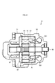
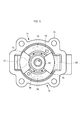
また、図3に示すように、ベーンポンプ5は、後述する油圧供給回路60のメイン側油路a1に油圧を供給するメイン側ポンプ部71と、サブ側油路a2に油圧を供給するサブ側ポンプ部72とを備えている。メイン側ポンプ部71は、メイン側吸入ポート(第1の吸入ポート)73とメイン側吐出ポート74とを備え、サブ側ポンプ部72は、サブ側吸入ポート(第2の吸入ポート)75とサブ側吐出ポート76とを備えている。
メイン側吸入ポート73の下流側及びサブ側吸入ポート75の下流側には、メイン側吸入ポート73とサブ側吸入ポート75とを連通する連通油路79が配置されている。メイン側吐出ポート74は、メイン吐出圧室581に連通し、サブ側吐出ポート76は、サブ吐出圧室582に連通している(図2参照)。
更に、ベーンポンプ(O/P)5は、ポンプカバー51に開口して形成されたメイン側吸入口(第1の吸入口)81及びサブ側吸入口(第2の吸入口)82と、ポンプボディ50に開口して形成されたメイン側吐出口(第1の吐出口)83及びサブ側吐出口(第2の吐出口)84とを備えている(図4参照)。
メイン側吸入口81は、サクション油路66に連通され、メイン側吸入ポート73に対向して配置されている。即ち、メイン側吸入ポート73は、メイン側吸入口81に対向し、メイン側吸入口81から流入する油が流入する。サブ側吸入口82は、ストレーナ4に連通され、サブ側吸入ポート75に対向して配置されている。即ち、サブ側吸入ポート75は、サブ側吸入口82に対向し、サブ側吸入口82から流入する油が流入する。また、連通油路79は、メイン側吸入口81とサブ側吸入口82とを連通している。また、メイン側吐出口83は、後述する油圧供給回路60のメイン側油路a1に連通され、サブ側吐出口84は、油圧供給回路60のサブ側油路a2に連通されている。即ち、メイン側吐出口83は、メイン側吸入口81から流入する油を油圧供給回路60に吐出し、サブ側吐出口84は、サブ側吸入口82から流入する油を油圧供給回路60に吐出する。
ここで、図1に示すように、車両用駆動装置1において、ストレーナ4と、ベーンポンプ5と、バルブボディ6とは、ベーンポンプ5を中心にして、ストレーナ4とバルブボディ6とが水平方向に互いに反対側に配置されている。即ち、ベーンポンプ5に対して、ストレーナ4とは反対側にバルブボディ6を配置している。これにより、バルブボディ6をケース3の前面に設置できるので、車両の小型化に貢献することができる。
バルブボディ6は、ケース3の側面のうちの前面に設置されている(図1参照)。図4に示すように、バルブボディ(V/B)6は、変速機構2に油圧を供給する油圧供給回路60と、油圧供給回路60で余剰した余剰油圧P1を排出するサクション油路66とを有している。油圧供給回路60は、例えば、プライマリレギュレータバルブ61と、セカンダリレギュレータバルブ62と、第1のサブチェックバルブ63と、第2のサブチェックバルブ64と、潤滑チェックバルブ65とを備えている。
プライマリレギュレータバルブ61は、ベーンポンプ5のメイン側吐出口83にメイン側油路a1を介して連通されており、ベーンポンプ5のメイン側ポンプ部71から吐出された油圧をライン圧PLに調圧するようになっている。ライン圧PLは、例えば、変速機構2の不図示のプライマリプーリやセカンダリプーリの制御に使用される。
セカンダリレギュレータバルブ62は、プライマリレギュレータバルブ61から排出された油圧をセカンダリ圧Psecに調圧するようになっている。セカンダリ圧Psecは、例えば、変速機構2の不図示のトルクコンバータの制御に使用される。更に、セカンダリレギュレータバルブ62から排出された油圧は、例えば、変速機構2の潤滑油として使用され、一部は潤滑チェックバルブ65を介して余剰油圧P1としてサクション油路66からメイン側吸入口81に還流される。
また、ベーンポンプ5のサブ側ポンプ部72から吐出された油圧は、サブ側吐出口84からサブ側油路a2を介してプライマリレギュレータバルブ61に供給され、プライマリレギュレータバルブ61からセカンダリレギュレータバルブ62を経て変速機構2の潤滑油として使用されたり、一部は余剰油圧P1としてサクション油路66からメイン側吸入口81に還流される。尚、サブ側油路a2の油圧がメイン側油路a1の油圧より大きい場合は、第1のサブチェックバルブ63によって、サブ側油路a2の油圧がメイン側油路a1に流入してライン圧PLを生成するようになっている。同様に、プライマリレギュレータバルブ61から排出された時点でサブ側の油圧がメイン側の油圧より大きい場合は、第2のサブチェックバルブ64によって、サブ側の油圧がメイン側に流入してセカンダリ圧Psecを生成するようになっている。
次に、車両用駆動装置1の動作について説明する。
不図示の駆動源が始動し、ベーンポンプ5が低速回転で作動されると、メイン側ポンプ部71はメイン側吸入口81から油を吸入すると同時に、サブ側ポンプ部72はサブ側吸入口82から油を吸入する。ここで、駆動源が始動したばかりで回転速度が低速である時は、ベーンポンプ5の吐出量が少なく、油圧供給回路60からの余剰流量が少ないため、サクション油路66からの油の流入は期待できないが、サブ側吸入口82から吸入した油を、連通油路79を介してメイン側ポンプ部71へ必要十分量の油を供給する事で、メイン側ポンプ部71で発生する圧力損失を抑え、キャビテーションの発生を抑制する。
駆動源が高速で駆動し、ベーンポンプ5が高速回転で作動されると、ベーンポンプ5の吐出が増え、余剰流量が多くなる。余剰流量がストレーナ4から吸入した流量よりも大きい場合、余剰流量を連通油路79を介してサブ側ポンプ部72へ油を供給する事で、圧力損失を抑え、キャビテーションの発生を抑制する。
以上説明したように、本実施の形態の車両用駆動装置1によると、ベーンポンプ5のメイン側吸入口81がサクション油路66に連通されると共に、サブ側吸入口82がストレーナ4に連通されるので、バルブボディ6がベーンポンプ5を介してストレーナ4の反対側に配置される場合、油路を合流させることなく配置することができる。これにより、設計の自由度を向上することができる。
また、本実施の形態の車両用駆動装置1では、ベーンポンプ5のメイン側吸入口81がサクション油路66に連通されると共に、サブ側吸入口82がストレーナ4に連通されるので、ストレーナ4の油だけでなくバルブボディ6からの余剰油圧P1を吸入することができる。このため、ストレーナ4の油だけを吸入する場合に比べて吸入時の圧力損失が小さくなるので、キャビテーションの発生を抑制することができる。
また、本実施の形態の車両用駆動装置1では、ベーンポンプ5は、メイン側吸入口81とサブ側吸入口82とを連通する連通油路79を有している。このため、ベーンポンプ5の低速回転時には、サブ側吸入口82から吸入した油圧は連通油路79を流通してメイン側吸入ポート73に回り込んで流入することができる。また、ベーンポンプ5の高速回転時には、メイン側吸入ポート73の油圧は連通油路79を流通してサブ側吸入ポート75に回り込んで流入するようになるので、サブ側ポンプ部72で発生した圧力損失が補われ、キャビテーションの発生を抑制することができる。
また、本実施の形態の車両用駆動装置1では、ベーンポンプ5に対して、ストレーナ4とは反対側にバルブボディ6を配置している。これにより、バルブボディ6をケース3の前面に設置できるので、車両の小型化に貢献することができる。
また、本実施の形態の車両用駆動装置1では、バルブボディ6はケース3の側面に設置され、ベーンポンプ5はケース3の内部に設置されるようにしている。このため、自動車等の車両に好適に適用することができる。特に本実施の形態では、バルブボディ6はケース3の前面に設置されていることから、車両の小型化に貢献することができる。
尚、上述した本実施の形態においては、メイン側吸入口81にサクション油路66を連通すると共に、サブ側吸入口82にストレーナ4を連通する場合について説明したが、これには限られない。例えば、メイン側吸入口81にストレーナ4を連通すると共に、サブ側吸入口82にサクション油路66を連通するようにしてもよい。
また、上述した本実施の形態においては、油圧供給回路60は、プライマリレギュレータバルブ61及びセカンダリレギュレータバルブ62を備えている場合について説明したが、これには限られない。例えば、セカンダリレギュレータバルブ62を有さず、セカンダリ圧Psecが発生しない油圧供給回路としてもよい。この場合、プライマリレギュレータバルブ61から排出された油圧をサクション油路66に供給するようにできる。
尚、本実施の形態は、以下の構成を少なくとも備える。本実施の形態の伝達装置(1)は、伝達機構(2)を収容するケース(3)と、前記ケース(3)の下部(3a)に貯留した油を吸引するためのストレーナ(4)と、前記伝達機構(2)に油圧を供給する油圧供給回路(60)と、前記油圧供給回路(60)で余剰した余剰油圧(P1)を排出するサクション油路(66)とを有するバルブボディ(6)と、前記サクション油路(66)及び前記ストレーナ(4)の一方と連通された第1の吸入口(81)と、前記サクション油路(66)及び前記ストレーナ(4)の他方と連通された第2の吸入口(82)と、前記第1の吸入口(81)に対向し、前記第1の吸入口(81)から流入する油が流入する第1の吸入ポート(73)と、前記第2の吸入口(82)に対向し、前記第2の吸入口(82)から流入する油が流入する第2の吸入ポート(75)と、前記第1の吸入口(81)及び前記第2の吸入口(82)から流入する油を前記油圧供給回路(60)に吐出する第1の吐出口(83)及び第2の吐出口(84)と、前記第1の吸入ポート(73)の下流側及び前記第2の吸入ポート(75)の下流側に配置され前記第1の吸入ポート(73)と前記第2の吸入ポート(75)とを連通する連通油路(79)と、を有する平衡形のベーンポンプ(5)と、を備える。
この構成によれば、ベーンポンプ(5)の第1の吸入口(81)がサクション油路(66)に連通されると共に、第2の吸入口(82)がストレーナ(4)に連通されるので、バルブボディ(6)がベーンポンプ(5)を介してストレーナ(4)の反対側に配置される場合、油路を合流させることなく配置することができる。これにより、設計の自由度を向上することができる。また、サクション油路(66)とストレーナ(4)とからの流量を連通油路(79)によって第1及び第2の吸入ポート(73,75)へ供給するので、ストレーナ(4)の油だけでなくバルブボディ(6)からの余剰油圧(P1)を吸入することができる。このため、ストレーナ(4)の油だけを吸入する場合に比べて吸入する油圧が高くなるので、ベーンポンプ(5)の低速回転時や高速回転時におけるキャビテーションの発生を抑制することができる。
また、本実施の形態の伝達装置(1)は、前記ベーンポンプ(5)に対して、前記ストレーナ(4)とは反対側に前記バルブボディ(6)を配置する。この構成によれば、バルブボディ(6)をケース(3)の前面に設置できるので、車両の小型化に貢献することができる。
本伝達装置は、自動車等の車両に適用されて好適な伝達装置に係り、詳しくは、伝達機構に供給する作動油や潤滑油の油圧を生成するオイルポンプとしてベーンポンプを適用した伝達装置に用いて好適である。
1 車両用駆動装置(伝達装置)
2 変速機構(伝達機構)
3 ケース
3a ケースの下部
4 ストレーナ
5 ベーンポンプ
6 バルブボディ
7 油
60 油圧供給回路
66 サクション油路
73 メイン側吸入ポート(第1の吸入ポート)
75 サブ側吸入ポート(第2の吸入ポート)
79 連通油路(連通油路)
81 メイン側吸入口(第1の吸入口)
82 サブ側吸入口(第2の吸入口)
83 メイン側吐出口(第1の吐出口)
84 サブ側吐出口(第2の吐出口)
P1 余剰油圧
2 変速機構(伝達機構)
3 ケース
3a ケースの下部
4 ストレーナ
5 ベーンポンプ
6 バルブボディ
7 油
60 油圧供給回路
66 サクション油路
73 メイン側吸入ポート(第1の吸入ポート)
75 サブ側吸入ポート(第2の吸入ポート)
79 連通油路(連通油路)
81 メイン側吸入口(第1の吸入口)
82 サブ側吸入口(第2の吸入口)
83 メイン側吐出口(第1の吐出口)
84 サブ側吐出口(第2の吐出口)
P1 余剰油圧
Claims (2)
- 伝達機構を収容するケースと、
前記ケースの下部に貯留した油を吸引するためのストレーナと、
前記伝達機構に油圧を供給する油圧供給回路と、前記油圧供給回路で余剰した余剰油圧を排出するサクション油路とを有するバルブボディと、
前記サクション油路及び前記ストレーナの一方と連通された第1の吸入口と、前記サクション油路及び前記ストレーナの他方と連通された第2の吸入口と、
前記第1の吸入口に対向し、前記第1の吸入口から流入する油が流入する第1の吸入ポートと、前記第2の吸入口に対向し、前記第2の吸入口から流入する油が流入する第2の吸入ポートと、前記第1の吸入口及び前記第2の吸入口から流入する油を前記油圧供給回路に吐出する第1の吐出口及び第2の吐出口と、前記第1の吸入ポートの下流側及び前記第2の吸入ポートの下流側に配置され前記第1の吸入ポートと前記第2の吸入ポートとを連通する連通油路と、を有する平衡形のベーンポンプと、を備える伝達装置。 - 前記ベーンポンプに対して、前記ストレーナとは反対側に前記バルブボディを配置する請求項1記載の伝達装置。
Priority Applications (3)
| Application Number | Priority Date | Filing Date | Title |
|---|---|---|---|
| CN201680004919.5A CN107110154B (zh) | 2015-01-19 | 2016-01-06 | 传递装置 |
| DE112016000193.2T DE112016000193T5 (de) | 2015-01-19 | 2016-01-06 | Übertragungsvorrichtung |
| US15/539,434 US10641266B2 (en) | 2015-01-19 | 2016-01-06 | Transfer device |
Applications Claiming Priority (2)
| Application Number | Priority Date | Filing Date | Title |
|---|---|---|---|
| JP2015007547A JP6411228B2 (ja) | 2015-01-19 | 2015-01-19 | 伝達装置 |
| JP2015-007547 | 2015-01-19 |
Publications (1)
| Publication Number | Publication Date |
|---|---|
| WO2016117353A1 true WO2016117353A1 (ja) | 2016-07-28 |
Family
ID=56416902
Family Applications (1)
| Application Number | Title | Priority Date | Filing Date |
|---|---|---|---|
| PCT/JP2016/050198 Ceased WO2016117353A1 (ja) | 2015-01-19 | 2016-01-06 | 伝達装置 |
Country Status (5)
| Country | Link |
|---|---|
| US (1) | US10641266B2 (ja) |
| JP (1) | JP6411228B2 (ja) |
| CN (1) | CN107110154B (ja) |
| DE (1) | DE112016000193T5 (ja) |
| WO (1) | WO2016117353A1 (ja) |
Families Citing this family (4)
| Publication number | Priority date | Publication date | Assignee | Title |
|---|---|---|---|---|
| JP6411228B2 (ja) * | 2015-01-19 | 2018-10-24 | アイシン・エィ・ダブリュ株式会社 | 伝達装置 |
| JP2021017919A (ja) * | 2019-07-18 | 2021-02-15 | トヨタ自動車株式会社 | 車両用オイル供給装置 |
| DE102020124241A1 (de) | 2019-09-26 | 2021-04-01 | Aisin Aw Co., Ltd. | Flügelzellenpumpe |
| JP7466398B2 (ja) * | 2019-09-26 | 2024-04-12 | 株式会社アイシン | ベーンポンプ |
Citations (3)
| Publication number | Priority date | Publication date | Assignee | Title |
|---|---|---|---|---|
| JPH10306783A (ja) * | 1997-05-09 | 1998-11-17 | Honda Motor Co Ltd | 平衡型ベーンポンプ構造 |
| JP2010014101A (ja) * | 2008-06-05 | 2010-01-21 | Kayaba Ind Co Ltd | 多連式ベーンポンプ |
| JP2014126043A (ja) * | 2012-12-27 | 2014-07-07 | Showa Corp | ベーンポンプ |
Family Cites Families (21)
| Publication number | Priority date | Publication date | Assignee | Title |
|---|---|---|---|---|
| US4386891A (en) * | 1981-04-23 | 1983-06-07 | General Motors Corporation | Rotary hydraulic vane pump with undervane passages for priming |
| US5657629A (en) * | 1991-01-14 | 1997-08-19 | Folsom Technologies, Inc. | Method of changing speed and torque with a continuously variable vane-type machine |
| JP3573242B2 (ja) * | 1997-03-27 | 2004-10-06 | 株式会社ショーワ | ベーンポンプ |
| US6149409A (en) * | 1999-08-02 | 2000-11-21 | Ford Global Technologies, Inc. | Cartridge vane pump with dual side fluid feed and single side inlet |
| JP3717146B2 (ja) | 1999-12-17 | 2005-11-16 | 本田技研工業株式会社 | 作動油供給装置 |
| AU2001247846A1 (en) * | 2000-03-28 | 2001-10-08 | Hydraulic Controls, Inc. | Speed regulated oil delivery system |
| JP2003120497A (ja) * | 2001-10-16 | 2003-04-23 | Ebara Corp | ベーン式回転機械 |
| TW200406547A (en) * | 2002-06-05 | 2004-05-01 | Sanyo Electric Co | Internal intermediate pressure multistage compression type rotary compressor, manufacturing method thereof and displacement ratio setting method |
| US7290991B2 (en) * | 2004-02-18 | 2007-11-06 | General Motors Corporation | Dual oil supply pump |
| JP4471805B2 (ja) * | 2004-10-06 | 2010-06-02 | カヤバ工業株式会社 | ベーンポンプ |
| JP2007162554A (ja) * | 2005-12-13 | 2007-06-28 | Kayaba Ind Co Ltd | ベーンポンプ |
| JP5010965B2 (ja) * | 2007-04-20 | 2012-08-29 | トヨタ自動車株式会社 | 油圧制御装置 |
| JP4464984B2 (ja) * | 2007-04-20 | 2010-05-19 | トヨタ自動車株式会社 | 車両用オイル供給装置 |
| JP5282681B2 (ja) * | 2009-06-30 | 2013-09-04 | 株式会社ジェイテクト | ベーンポンプ |
| JP5278775B2 (ja) * | 2010-12-06 | 2013-09-04 | アイシン精機株式会社 | 油供給装置 |
| JP5783407B2 (ja) * | 2011-04-14 | 2015-09-24 | アイシン精機株式会社 | 油圧制御装置 |
| JP5897945B2 (ja) * | 2012-03-22 | 2016-04-06 | 日立オートモティブシステムズ株式会社 | ベーンポンプ |
| US20140271310A1 (en) * | 2013-03-14 | 2014-09-18 | Woodward, Inc. | Clubhead Vane Pump With Balanced Vanes |
| JP6411228B2 (ja) * | 2015-01-19 | 2018-10-24 | アイシン・エィ・ダブリュ株式会社 | 伝達装置 |
| US20180135625A1 (en) * | 2015-04-09 | 2018-05-17 | Hitachi Automotive Systems, Ltd. | Variable capacity oil pump |
| JP6708534B2 (ja) * | 2016-11-04 | 2020-06-10 | トヨタ自動車株式会社 | ベーン式オイルポンプ |
-
2015
- 2015-01-19 JP JP2015007547A patent/JP6411228B2/ja active Active
-
2016
- 2016-01-06 DE DE112016000193.2T patent/DE112016000193T5/de not_active Withdrawn
- 2016-01-06 WO PCT/JP2016/050198 patent/WO2016117353A1/ja not_active Ceased
- 2016-01-06 US US15/539,434 patent/US10641266B2/en active Active
- 2016-01-06 CN CN201680004919.5A patent/CN107110154B/zh active Active
Patent Citations (3)
| Publication number | Priority date | Publication date | Assignee | Title |
|---|---|---|---|---|
| JPH10306783A (ja) * | 1997-05-09 | 1998-11-17 | Honda Motor Co Ltd | 平衡型ベーンポンプ構造 |
| JP2010014101A (ja) * | 2008-06-05 | 2010-01-21 | Kayaba Ind Co Ltd | 多連式ベーンポンプ |
| JP2014126043A (ja) * | 2012-12-27 | 2014-07-07 | Showa Corp | ベーンポンプ |
Also Published As
| Publication number | Publication date |
|---|---|
| US20170356444A1 (en) | 2017-12-14 |
| CN107110154A (zh) | 2017-08-29 |
| JP2016133031A (ja) | 2016-07-25 |
| JP6411228B2 (ja) | 2018-10-24 |
| CN107110154B (zh) | 2019-10-18 |
| DE112016000193T5 (de) | 2017-08-24 |
| US10641266B2 (en) | 2020-05-05 |
Similar Documents
| Publication | Publication Date | Title |
|---|---|---|
| CN103703284B (zh) | 变速器用液压回路 | |
| JP6411228B2 (ja) | 伝達装置 | |
| WO2015111550A1 (ja) | ベーンポンプ | |
| JP2014077536A (ja) | 車両用自動変速機の油圧供給システム | |
| JP5589532B2 (ja) | ベーンポンプ | |
| US20110176909A1 (en) | Vehicle hydraulic control unit | |
| JP5278775B2 (ja) | 油供給装置 | |
| US9291163B2 (en) | Pump having fitting portions | |
| US9546728B2 (en) | Balanced binary pump for CVT transmission | |
| JP6196440B2 (ja) | 車両用自動変速機の油圧供給システム | |
| CN108019615B (zh) | 叶片式机油泵 | |
| CN106968946A (zh) | 车辆液压装置 | |
| US20140294650A1 (en) | Vane pump | |
| JP2015094296A (ja) | オイルポンプ装置およびリリーフ弁 | |
| JP6897412B2 (ja) | オイルポンプ | |
| JP2021055672A (ja) | ベーンポンプ | |
| JP2015203385A (ja) | 車両用油圧制御装置 | |
| JP6270684B2 (ja) | 油圧制御装置 | |
| US11396874B2 (en) | Vane pump including fluid communication passages for routing fluid received from two inflow passages around outer peripheral surface of the entire perimeter of the cam ring | |
| JP2017061866A (ja) | 可変オイルポンプ | |
| JP2006177230A (ja) | ポンプ装置 | |
| JP2009052525A (ja) | ベーンポンプ | |
| WO2017217223A1 (ja) | ベーンポンプ | |
| JP2022117255A (ja) | オイルポンプ | |
| JP2012202299A (ja) | ベーンポンプ |
Legal Events
| Date | Code | Title | Description |
|---|---|---|---|
| 121 | Ep: the epo has been informed by wipo that ep was designated in this application |
Ref document number: 16739960 Country of ref document: EP Kind code of ref document: A1 |
|
| WWE | Wipo information: entry into national phase |
Ref document number: 112016000193 Country of ref document: DE |
|
| WWE | Wipo information: entry into national phase |
Ref document number: 15539434 Country of ref document: US |
|
| 122 | Ep: pct application non-entry in european phase |
Ref document number: 16739960 Country of ref document: EP Kind code of ref document: A1 |