WO2016117316A1 - 燃料ポンプ及びその製造方法 - Google Patents
燃料ポンプ及びその製造方法 Download PDFInfo
- Publication number
- WO2016117316A1 WO2016117316A1 PCT/JP2016/000189 JP2016000189W WO2016117316A1 WO 2016117316 A1 WO2016117316 A1 WO 2016117316A1 JP 2016000189 W JP2016000189 W JP 2016000189W WO 2016117316 A1 WO2016117316 A1 WO 2016117316A1
- Authority
- WO
- WIPO (PCT)
- Prior art keywords
- pump
- discharge
- side end
- suction
- guide path
- Prior art date
- Legal status (The legal status is an assumption and is not a legal conclusion. Google has not performed a legal analysis and makes no representation as to the accuracy of the status listed.)
- Ceased
Links
Images




Classifications
-
- F—MECHANICAL ENGINEERING; LIGHTING; HEATING; WEAPONS; BLASTING
- F04—POSITIVE - DISPLACEMENT MACHINES FOR LIQUIDS; PUMPS FOR LIQUIDS OR ELASTIC FLUIDS
- F04C—ROTARY-PISTON, OR OSCILLATING-PISTON, POSITIVE-DISPLACEMENT MACHINES FOR LIQUIDS; ROTARY-PISTON, OR OSCILLATING-PISTON, POSITIVE-DISPLACEMENT PUMPS
- F04C2/00—Rotary-piston machines or pumps
- F04C2/08—Rotary-piston machines or pumps of intermeshing-engagement type, i.e. with engagement of co-operating members similar to that of toothed gearing
- F04C2/10—Rotary-piston machines or pumps of intermeshing-engagement type, i.e. with engagement of co-operating members similar to that of toothed gearing of internal-axis type with the outer member having more teeth or tooth-equivalents, e.g. rollers, than the inner member
-
- F—MECHANICAL ENGINEERING; LIGHTING; HEATING; WEAPONS; BLASTING
- F04—POSITIVE - DISPLACEMENT MACHINES FOR LIQUIDS; PUMPS FOR LIQUIDS OR ELASTIC FLUIDS
- F04C—ROTARY-PISTON, OR OSCILLATING-PISTON, POSITIVE-DISPLACEMENT MACHINES FOR LIQUIDS; ROTARY-PISTON, OR OSCILLATING-PISTON, POSITIVE-DISPLACEMENT PUMPS
- F04C15/00—Component parts, details or accessories of machines, pumps or pumping installations, not provided for in groups F04C2/00 - F04C14/00
- F04C15/06—Arrangements for admission or discharge of the working fluid, e.g. constructional features of the inlet or outlet
-
- F—MECHANICAL ENGINEERING; LIGHTING; HEATING; WEAPONS; BLASTING
- F02—COMBUSTION ENGINES; HOT-GAS OR COMBUSTION-PRODUCT ENGINE PLANTS
- F02M—SUPPLYING COMBUSTION ENGINES IN GENERAL WITH COMBUSTIBLE MIXTURES OR CONSTITUENTS THEREOF
- F02M37/00—Apparatus or systems for feeding liquid fuel from storage containers to carburettors or fuel-injection apparatus; Arrangements for purifying liquid fuel specially adapted for, or arranged on, internal-combustion engines
- F02M37/04—Feeding by means of driven pumps
- F02M37/08—Feeding by means of driven pumps electrically driven
-
- F—MECHANICAL ENGINEERING; LIGHTING; HEATING; WEAPONS; BLASTING
- F02—COMBUSTION ENGINES; HOT-GAS OR COMBUSTION-PRODUCT ENGINE PLANTS
- F02M—SUPPLYING COMBUSTION ENGINES IN GENERAL WITH COMBUSTIBLE MIXTURES OR CONSTITUENTS THEREOF
- F02M37/00—Apparatus or systems for feeding liquid fuel from storage containers to carburettors or fuel-injection apparatus; Arrangements for purifying liquid fuel specially adapted for, or arranged on, internal-combustion engines
- F02M37/04—Feeding by means of driven pumps
- F02M37/08—Feeding by means of driven pumps electrically driven
- F02M37/10—Feeding by means of driven pumps electrically driven submerged in fuel, e.g. in reservoir
-
- F—MECHANICAL ENGINEERING; LIGHTING; HEATING; WEAPONS; BLASTING
- F04—POSITIVE - DISPLACEMENT MACHINES FOR LIQUIDS; PUMPS FOR LIQUIDS OR ELASTIC FLUIDS
- F04C—ROTARY-PISTON, OR OSCILLATING-PISTON, POSITIVE-DISPLACEMENT MACHINES FOR LIQUIDS; ROTARY-PISTON, OR OSCILLATING-PISTON, POSITIVE-DISPLACEMENT PUMPS
- F04C15/00—Component parts, details or accessories of machines, pumps or pumping installations, not provided for in groups F04C2/00 - F04C14/00
- F04C15/0042—Systems for the equilibration of forces acting on the machines or pump
- F04C15/0049—Equalization of pressure pulses
-
- F—MECHANICAL ENGINEERING; LIGHTING; HEATING; WEAPONS; BLASTING
- F04—POSITIVE - DISPLACEMENT MACHINES FOR LIQUIDS; PUMPS FOR LIQUIDS OR ELASTIC FLUIDS
- F04C—ROTARY-PISTON, OR OSCILLATING-PISTON, POSITIVE-DISPLACEMENT MACHINES FOR LIQUIDS; ROTARY-PISTON, OR OSCILLATING-PISTON, POSITIVE-DISPLACEMENT PUMPS
- F04C2/00—Rotary-piston machines or pumps
- F04C2/08—Rotary-piston machines or pumps of intermeshing-engagement type, i.e. with engagement of co-operating members similar to that of toothed gearing
- F04C2/10—Rotary-piston machines or pumps of intermeshing-engagement type, i.e. with engagement of co-operating members similar to that of toothed gearing of internal-axis type with the outer member having more teeth or tooth-equivalents, e.g. rollers, than the inner member
- F04C2/102—Rotary-piston machines or pumps of intermeshing-engagement type, i.e. with engagement of co-operating members similar to that of toothed gearing of internal-axis type with the outer member having more teeth or tooth-equivalents, e.g. rollers, than the inner member the two members rotating simultaneously around their respective axes
-
- F—MECHANICAL ENGINEERING; LIGHTING; HEATING; WEAPONS; BLASTING
- F04—POSITIVE - DISPLACEMENT MACHINES FOR LIQUIDS; PUMPS FOR LIQUIDS OR ELASTIC FLUIDS
- F04C—ROTARY-PISTON, OR OSCILLATING-PISTON, POSITIVE-DISPLACEMENT MACHINES FOR LIQUIDS; ROTARY-PISTON, OR OSCILLATING-PISTON, POSITIVE-DISPLACEMENT PUMPS
- F04C2230/00—Manufacture
- F04C2230/10—Manufacture by removing material
-
- F—MECHANICAL ENGINEERING; LIGHTING; HEATING; WEAPONS; BLASTING
- F04—POSITIVE - DISPLACEMENT MACHINES FOR LIQUIDS; PUMPS FOR LIQUIDS OR ELASTIC FLUIDS
- F04C—ROTARY-PISTON, OR OSCILLATING-PISTON, POSITIVE-DISPLACEMENT MACHINES FOR LIQUIDS; ROTARY-PISTON, OR OSCILLATING-PISTON, POSITIVE-DISPLACEMENT PUMPS
- F04C2240/00—Components
- F04C2240/30—Casings or housings
-
- F—MECHANICAL ENGINEERING; LIGHTING; HEATING; WEAPONS; BLASTING
- F04—POSITIVE - DISPLACEMENT MACHINES FOR LIQUIDS; PUMPS FOR LIQUIDS OR ELASTIC FLUIDS
- F04C—ROTARY-PISTON, OR OSCILLATING-PISTON, POSITIVE-DISPLACEMENT MACHINES FOR LIQUIDS; ROTARY-PISTON, OR OSCILLATING-PISTON, POSITIVE-DISPLACEMENT PUMPS
- F04C2250/00—Geometry
- F04C2250/10—Geometry of the inlet or outlet
Definitions
- the present disclosure relates to a fuel pump that sequentially sucks fuel into each pump chamber and then discharges the fuel pump, and a manufacturing method thereof.
- Patent Document 1 discloses an oil pump as a technique applicable to a fuel pump that sequentially sucks fuel into each pump chamber and then discharges it.
- the pump includes an outer gear having a plurality of inner teeth, an inner gear having a plurality of outer teeth, the outer gear being eccentrically engaged with the outer gear, and a pump housing for rotatably housing the outer gear and the inner gear in the circumferential direction. ing.
- the outer gear and the inner gear rotate while expanding and contracting the volume of a plurality of pump chambers formed between the two gears, so that oil is sequentially sucked into each pump chamber and then discharged.
- the pump housing further includes a sliding surface on which the outer gear and the inner gear slide, and a guide path that is recessed from the sliding surface and extends in the circumferential direction, and a suction guide path that sucks oil into the pump chamber and the oil from the pump chamber.
- the pump chamber forms a closed space between the suction side end and the discharge side end.
- Patent Document 1 it is considered that the shape of the discharge side end is set so as not to hinder the formation of the above-described room. For this reason, for example, the distance between the outer peripheral portion of the suction side end portion and the outer peripheral portion of the discharge side end portion is relatively short with respect to the intermediate portion.
- this configuration is applied to a fuel pump, there is a concern that fuel leaks from the discharge guide path to the suction guide path through the sliding surface, resulting in a decrease in pump efficiency.
- the present disclosure has been made in view of the problems described above, and an object thereof is to provide a fuel pump with high pump efficiency and a method for manufacturing the same.
- a fuel pump includes an outer gear having a plurality of inner teeth, an inner gear having a plurality of outer teeth, the outer gear being eccentrically engaged with the outer gear, and the outer gear and the inner gear.
- a pump housing that is rotatably accommodated, and the outer gear and the inner gear rotate while expanding and contracting the volume of a plurality of pump chambers formed between the two gears, thereby sequentially sucking fuel into the pump chambers.
- the pump housing is discharged from each pump chamber, and the pump housing sucks fuel into the pump chamber as a sliding surface on which the outer gear and the inner gear slide, and a guide path that is recessed from the sliding surface and extends in the circumferential direction of the pump housing.
- a suction guide path and a discharge guide path for discharging fuel from the pump chamber as a guide path that is recessed from the sliding surface and extends in the circumferential direction;
- the suction-side end of the suction guide path and the discharge-side end of the discharge guide path are opposed to each other with a space therebetween, and at a declination where the reduction of the pump chamber is started,
- the outer peripheral portion is formed along the inner teeth, and the inner peripheral portion is formed along the outer teeth.
- the outer peripheral portion of the discharge side end portion is formed along the inner teeth of the outer gear at the deflection angle at which the pump chamber starts to shrink.
- the inner peripheral portion of the discharge side end portion is formed along the outer teeth of the inner gear at the deflection angle at which the pump chamber starts to shrink.
- the processing tool for rotational cutting in a circular shape is drawn with one stroke so as to form the outline of the discharge guide path including the discharge side end.
- the machining tool is circulated in a single stroke so as to form the outline of the suction guide path including the suction side end portion.
- the discharge guide path is formed by circularly moving a processing tool that rotates and cuts in a circular shape so as to form a contour of the discharge guide path including the discharge side end portion. Is formed.
- the discharge guide path can be formed without changing the processing tool, it is possible to suppress the occurrence of burrs or the like that may occur when the processing tool is changed. For this reason, the fuel pump in which the outer peripheral part along the inner teeth and the inner peripheral part along the outer teeth are formed can be easily manufactured. Moreover, productivity can be improved by forming the suction guide path in the same manner.
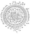
- FIG. 2 is a view showing a pump body and a pump housing in a section taken along line II-II in FIG. 1.
- FIG. 3 is a view showing a pump body and a pump housing in a section taken along line III-III in FIG. 1.
- FIG. 4 is a sectional view taken along line IV-IV in FIG. 1.
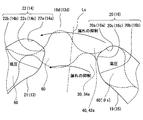
- It is a schematic diagram for demonstrating the discharge side end part and suction
- FIG. 10 is a diagram corresponding to FIG. 3 in Modification 5.
- a fuel pump 100 is a positive displacement trochoid pump mounted on a vehicle.
- the fuel pump 100 includes a pump body 3 and an electric motor 4 housed in a cylindrical pump body 2.
- the fuel pump 100 includes a side cover 5 that projects from the end opposite to the pump body 3 to the outside with the electric motor 4 in the axial direction of the pump body 2.
- the side cover 5 includes an electrical connector 5a for energizing the electric motor and a discharge port 5b for discharging fuel.
- the electric motor 4 is rotationally driven by energization from an external circuit via the electrical connector 5a.
- the fuel sucked and pressurized by the pump body 3 using the rotational force of the rotating shaft 4a of the electric motor 4 is discharged from the discharge port 5b.
- the light oil whose viscosity is higher than gasoline is discharged as a fuel.
- the pump body 3 includes a pump housing 10, an inner gear 30 and an outer gear 40.
- the pump housing 10 is formed by overlapping the pump cover 12 and the pump casing 18.
- the pump cover 12 is formed in a disk shape from metal.
- the pump cover 12 projects outward from an end of the pump body 2 opposite to the side cover 5 with the electric motor 4 sandwiched in the axial direction.
- the pump cover 12 shown in FIGS. 1 and 2 has a cylindrical hole-like inlet 12a and an arc-shaped groove-like inlet passage 13 for sucking fuel from the outside.
- the suction port 12 a passes through a specific portion Ss of the pump cover 12 that is eccentric from the inner center line Cig of the inner gear 30 along the axial direction of the cover 12.
- the suction passage 13 opens on the pump casing 18 side by penetrating the sliding surface 12b on the pump casing 18 side in the pump cover 12 along the axial direction.
- the inner periphery extending portion 13 b of the suction passage 13 extends to a length less than a half periphery along the rotational direction Rig (see also FIG. 4) of the inner gear 30.
- the outer periphery extending portion 13a of the suction passage 13 extends to a length less than a half periphery along the rotational direction Rog (see also FIG. 4) of the outer gear 40.
- the suction passage 13 is widened from the arcuate start end portion 13c toward the suction side end portion 14 as the end portion in the rotational directions Rig and Rog.
- the suction passage 13 communicates with the suction port 12a by opening the suction port 12a at a specific location Ss of the groove bottom 13d.
- the width of the suction passage 13 is set to be smaller than the diameter of the suction port 12a in the entire area of the specific portion Ss where the suction port 12a opens.
- the pump casing 18 shown in FIGS. 1, 3, and 4 is formed of a metal in a bottomed cylindrical shape.
- the opening 18 a in the pump casing 18 is covered with the pump cover 12, so that the entire circumference is sealed.
- the inner peripheral portion 18 b of the pump casing 18 is formed in a cylindrical hole shape that is eccentric from the inner center line Cig of the inner gear 30.
- the pump casing 18 forms an arc-hole-like discharge passage 19 in order to discharge fuel from the discharge port 5 b through the fuel passage 6 between the pump body 2 and the electric motor 4.
- the discharge passage 19 penetrates the sliding surface 18d which is the bottom surface of the concave bottom portion 18c of the pump casing 18 along the axial direction.
- the inner peripheral extending portion 19 b of the discharge passage 19 extends along the rotational direction Rig of the inner gear 30 to a length of less than a half periphery.
- the outer peripheral extending portion 19a of the discharge passage 19 extends along the rotational direction Rog of the outer gear 40 to a length of less than a half periphery.
- the discharge passage 19 is reduced in width toward the arcuate end portion 19c in the rotation direction Rig, Rog from the discharge side end portion 20 as the start end portion.
- an arc groove-shaped suction groove path 21 is formed in the portion of the concave bottom portion 18c of the pump casing 18 that faces the suction passage 13 across the pump chamber 60 (detailed later) between the two gears 30 and 40.
- an arc groove-shaped suction groove path 21 is formed in the pump casing 18.
- the contour of the discharge passage 19 and the contour of the suction groove 21 are provided substantially line symmetrically. Accordingly, the suction groove path 21 is widened from the arcuate start end portion 21a toward the suction side end portion 22 as the end portion in the rotational directions Rig and Rog.
- a portion of the pump cover 12 that faces the discharge passage 19 across the pump chamber 60 has an arc groove shape corresponding to the shape projected in the axial direction of the discharge passage 19.
- the discharge groove path 15 is formed.
- the suction passage 13 and the suction groove passage 21 are recessed from the corresponding sliding surfaces 12b and 18d in the pump housing 10 as suction guide passages extending in the circumferential direction of the pump housing 10, and the fuel is supplied to the pump chamber 60. Shaped for inhalation. Further, as a discharge guide path extending in the circumferential direction of the pump housing 10, the discharge path 19 and the discharge groove path 15 are recessed from the corresponding sliding surfaces 18 d and 12 b in the pump housing 10, respectively, and the fuel is discharged from the pump chamber 60. Is formed for.
- a radial bearing 50 is fitted and fixed on the inner center line Cig of the concave bottom portion 18 c of the pump casing 18 in order to radially support the rotating shaft 4 a of the electric motor 4.
- a thrust bearing 52 is fitted and fixed on the inner center line Cig of the pump cover 12 in order to support the rotary shaft 4a in the axial direction.
- the concave bottom portion 18 c and the inner peripheral portion 18 b of the pump casing 18 define an accommodation space 56 for accommodating the inner gear 30 and the outer gear 40 in cooperation with the pump cover 12.
- the inner gear 30 and the outer gear 40 are so-called trochoid gears in which the tooth profile curve of each tooth is a trochoid curve.
- the inner gear 30 is arranged eccentrically in the accommodation space 56 by sharing the inner center line Cig with the rotating shaft 4a.
- the inner peripheral portion 32 of the inner gear 30 is radially supported by the radial bearing 50 and is axially supported by the sliding surface 18 d of the pump casing 18 and the sliding surface 12 b of the pump cover 12.
- the inner gear 30 is provided with a plurality of insertion holes 37 along the axial direction. By inserting a plurality of corresponding foot portions 54a of the joint member 54 into the insertion holes 37, the inner gear 30
- the rotary shaft 4a is connected via a joint member 54. In this way, the inner gear 30 can rotate in a certain rotational direction Rig around the inner center line Cig in accordance with the rotation of the rotating shaft 4 a by the electric motor 4.
- the inner gear 30 has a plurality of external teeth 34 a arranged at equal intervals in the rotation direction Rig on the outer peripheral portion 34.
- Each external tooth 34a can be opposed to each of the passages 13 and 19 and each of the grooves 15 and 21 in the axial direction according to the rotation of the inner gear 30, thereby suppressing sticking to the sliding surfaces 12b and 18d.
- the outer gear 40 is arranged coaxially in the accommodation space 56 by being eccentric with respect to the inner center line Cig of the inner gear 30.
- the inner gear 30 is eccentric in the eccentric direction De as the one radial direction.
- the outer peripheral portion 44 of the outer gear 40 is radially supported by the inner peripheral portion 18b of the pump casing 18, and is axially supported by the sliding surface 18d of the pump casing 18 and the sliding surface 12b of the pump cover 12. ing.
- the outer gear 40 is rotatable in a certain rotational direction Rog around the outer center line Cog that is eccentric from the inner center line Cig.
- the outer gear 40 has a plurality of inner teeth 42 a arranged at equal intervals in the rotation direction Rog in the inner peripheral portion 42.
- the number of inner teeth 42 a in the outer gear 40 is set to be one greater than the number of outer teeth 34 a in the inner gear 30.
- Each inner tooth 42a can be opposed to each passage 13, 19 and each groove 15, 21 in the axial direction according to the rotation of the outer gear 40, thereby suppressing sticking to the sliding surfaces 12b, 18d. Has been.
- the inner gear 30 is engaged with the outer gear 40 by relative eccentricity in the eccentric direction De.
- a plurality of pump chambers 60 are formed between the gears 30 and 40 in the accommodation space 56.
- the volume of the pump chamber 60 expands and contracts as the outer gear 40 and the inner gear 30 rotate.
- the volume of the pump chamber 60 expands in the pump chamber 60 that communicates with the suction passage 13 and the suction groove passage 21.
- fuel is sucked into the pump chamber 60 through the suction passage 13 from the suction port 12a.
- the suction passage 13 is widened from the start end portion 13c toward the suction side end portion 14 (see also FIG. 2), the amount of fuel sucked through the suction passage 13 is the volume of the pump chamber 60. It depends on the amount of enlargement.
- the volume of the pump chamber 60 is reduced in the pump chamber 60 that is in communication with the discharge passage 19 and the discharge groove 15.
- fuel is discharged from the pump chamber 60 to the fuel passage 6 through the discharge passage 19.
- the discharge passage 19 is reduced in width toward the end portion 19c from the discharge side end portion 20 (see also FIG. 3), so that the amount of fuel discharged through the discharge passage 19 is reduced in the pump chamber 60. This is in accordance with the volume reduction amount.
- the fuel is sequentially sucked into the pump chambers 60 by the fuel pump 100 and discharged from the pump chambers 60, and the fuel pressure on the discharge passage 19 and the discharge groove 15 side is the suction passage. 13 and the fuel pressure on the suction groove 21 side are in a high pressure state.
- the reference axis Ae is defined in the eccentric direction De of the inner gear 30 with respect to the outer gear 40, and the deflection angle ⁇ from the reference axis Ae is defined in the rotational direction Rig of the inner gear 30.
- each pump chamber 60 When the deviation angle ⁇ in each pump chamber 60 reaches a predetermined start deviation angle ⁇ s as the both gears 30 and 40 rotate, the volume of the pump chamber 60 starts to expand and starts to decrease. It has become. That is, the reduction of each pump chamber 60 is always started at the same starting deflection angle ⁇ s with respect to the discharge passage 19 and the discharge groove 15 of the pump housing 10.
- the contour shape of the discharge side end portion 20 of the discharge passage 19 and the contour shape of the discharge side end portion 16 of the discharge groove 15 are associated with the tooth profile at the start deflection angle ⁇ s.
- the contours of the outer peripheral portions 20 a and 16 a of the discharge side end portions 20 and 16 are formed along the inner teeth 42 a of the outer gear 40 at the start deflection angle ⁇ s. More specifically, the contours of the outer peripheral portions 20a and 16a are formed to be concavely curved along the tooth profile curve of the inner tooth 42a.
- the contours of the inner peripheral portions 20 b and 16 b of the discharge side end portions 20 and 16 are formed along the outer teeth 34 a of the inner gear 30. More specifically, the contours of the inner peripheral portions 20b and 16b are formed to be concavely curved along the tooth profile curve of the outer teeth 34a.
- the contours of the intermediate portions 20c and 16c connecting the outer peripheral portions 20a and 16a and the inner peripheral portions 20b and 16b, respectively, are concave toward the suction side end portions 22 and 14. It is curved.
- the arc-shaped intermediate portions 20c and 16c are formed such that the curvature radius Rm thereof coincides with the curvature radius Rt of the end portions 19c and 15a, respectively.
- the pump chamber 60 that reaches the start deflection angle ⁇ s reliably communicates with the discharge passage 19 and the discharge groove passage 15 even in the vicinity of the intermediate portions 20c and 16c.
- the contours of the suction side end portions 22, 14 form a radial symmetry line Ls in the direction of a predetermined deviation angle ⁇ (for example, 195 °) from the center of the rotation shaft 4 a.
- the discharge-side end portions 20 and 16 are line symmetrical with respect to each other.
- the suction side end 22 of the suction groove 21 and the discharge side end 20 of the discharge passage 19 are opposed to each other with a gap in the circumferential direction of the pump housing 10.
- the suction side end 14 of the suction passage 13 and the discharge side end 16 of the discharge groove 15 are opposed to each other with a space therebetween in the circumferential direction.
- the discharge side end portions 20 and 16 at the outer peripheral portions 20a and 16a are respectively connected to the suction side end portion 22 via the sliding surfaces 18d and 12b on which the inner teeth 42a of the outer gear 40 slide. , 14 away in the circumferential direction.
- the discharge side end portions 20 and 16 are respectively connected to the suction side end portions 22 and 14 in the circumferential direction via sliding surfaces 18d and 12b on which the outer teeth 34a of the inner gear 30 slide. Going away.
- the interval between the intermediate portions 20c, 22c facing each other in the circumferential direction is smaller than the interval between the outer peripheral portions 20a, 22a and the interval between the inner peripheral portions 20b, 22b.
- the interval between the intermediate portions 16c and 14c facing each other in the circumferential direction is smaller than the interval between the outer peripheral portions 16a and 14a and the interval between the inner peripheral portions 16b and 14b. 4 and 5, the pump chamber 60 at the moment when the start deflection angle ⁇ s is reached is shown as 60 [ ⁇ s].
- the pump casing 18 side is shown as a representative, and the pump cover 12 side is not shown.
- each guide path in the present embodiment is performed, for example, by controlling the operation of the processing tool 72 provided in the machining center 70 in which the pump housing 10 is set by a computer program or the like.
- the processing tool 72 in the present embodiment a cutter that performs rotary cutting in a circular shape is used, and as the cutting radius Rc, a curvature radius Rm and a curvature radius that substantially coincides with the curvature radius Rt are selected.
- a discharge passage 19 is formed in the pump casing 18 and a discharge groove 15 is formed in the pump cover 12.
- the processing tool 72 that rotates and cuts in a circular shape is moved around in a single stroke so as to form the outline of the discharge passage 19 including the discharge side end portion 20.
- the discharge passage 19 is formed by cutting the processing tool 72 so as to penetrate the concave bottom portion 18 c of the pump casing 18.
- the processing tool 72 is moved around in a single stroke so as to form the contour of the discharge groove 15 including the discharge side end portion 16.
- the discharge groove 15 is formed by cutting the pump cover 12 to a predetermined depth from the sliding surface 12b by the processing tool 72.
- the suction guide path cutting step for forming the suction groove path 21 or the suction path 13 as the suction guide path in the pump housing 10 will be described here.
- the suction casing 21 is formed in the pump casing 18, and the suction passage 13 is formed in the pump cover 12.
- the processing tool 72 is moved around in a single stroke so as to form the contour of the suction groove 21 including the suction side end 22.
- the suction groove 21 is formed by cutting the pump casing 18 to a predetermined depth from the sliding surface 18d by the processing tool 72.
- the processing tool 72 is moved around in a single stroke so as to form the outline of the suction passage 13 including the suction side end portion 14.
- the discharge guide path cutting process and the suction guide path cutting process are in no particular order. Further, after the discharge passage 19 and the suction groove passage 21 in the pump casing 18 are formed, the discharge groove passage 15 and the suction passage 13 in the pump cover 12 may be formed. Further, the discharge passage 19 and the suction groove 21 in the pump casing 18 may be formed by a certain machining center 70, and the discharge groove 15 and the suction passage 13 in the pump cover 12 may be formed by another machining center 70. Further, instead of the machining center 70, a machining tool 72 provided in a composite lathe or the like may be used.
- the outer peripheral portions 20a and 16a of the discharge side end portions 20 and 16 are formed along the inner teeth 42a of the outer gear 40 at the deflection angle ⁇ s at which the pump chamber 60 starts to shrink.
- the inner peripheral portions 20 b and 16 b of the discharge side end portions 20 and 16 are formed along the outer teeth 34 a of the inner gear 30 at the deflection angle ⁇ s at which the pump chamber 60 starts to shrink.
- the fuel is smoothly discharged into the discharge passage 19 as the pump chamber 60 starts to shrink. Since the pulsation is started, both gears 30 and 40 can be smoothly rotated.
- the outer peripheral portions 20 a and 16 a and the inner peripheral portions 20 b and 16 b of the discharge side end portions 20 and 16 are spaced away from the suction side end portions 22 and 14 in the circumferential direction. For this reason, it is possible to prevent the fuel from leaking from the discharge passage 19 to the suction groove 21 via the sliding surface 18d or from the discharge groove 15 to the suction passage 13 via the sliding surface 12b. As described above, a fuel pump with high pump efficiency can be provided.
- the intermediate portions 20 c and 16 c connecting the outer peripheral portions 20 a and 16 a and the inner peripheral portions 20 b and 16 b face the suction side end portions 22 and 14. And curved in a convex shape. Since the outer peripheral portions 20a, 16a and the inner peripheral portions 20b, 16b are connected by such intermediate portions 20c, 16c, the discharge end portions 20, 16 as a whole are close to the shapes of both gears 30, 40. Since the discharge of the fuel into the discharge passage 19 starts smoothly, the pump efficiency is increased.
- the suction side end portions 22 and 14 have a line symmetrical shape with respect to the discharge side end portions 20 and 16. Because of the suction side end portions 22 and 14, the outer peripheral portions 20 a and 16 a and the inner peripheral portions 20 b and 16 b of the discharge side end portions 20 and 16 are reliably moved away from the suction side end portions 22 and 14. The effect of suppressing fuel leakage is enhanced.
- the processing tool 72 that rotates and cuts into a circular shape is used for the outline of the discharge passage 19 including the discharge side end 20 or the discharge groove 15 including the discharge side end 16.
- the discharge passage 19 or the discharge groove passage 15 is formed by circularly moving in a single stroke so as to form an outline.
- the fuel pump 100 in which the outer peripheral portion 20a or 16a along the inner teeth 42a and the inner peripheral portion 20b or 16b along the outer teeth 34a are formed can be easily manufactured.
- productivity can be improved by forming the suction groove path 21 or the suction path 13 in the same manner.
- the fuel pump 100 manufactured in this way as the pump chamber 60 starts to shrink, the fuel starts to be smoothly discharged into the discharge passage 19, so that the pulsation is suppressed and both the gears 30 and 40 are smoothly moved. Can be rotated. Further, the outer peripheral portions 20 a and 16 a and the inner peripheral portions 20 b and 16 b of the discharge side end portions 20 and 16 are spaced away from the suction side end portions 22 and 14 in the circumferential direction. For this reason, it is possible to prevent the fuel from leaking from the discharge passage 19 to the suction groove 21 via the sliding surface 18d or from the discharge groove 15 to the suction passage 13 via the sliding surface 12b. As described above, the fuel pump 100 with high pump efficiency can be easily manufactured.
- the curvature radius Rm and the curvature radius Rt do not have to coincide with each other in one guide path. Further, the curvature radii Rm and Rt may not coincide with the cutting radius Rc of the processing tool 72.
- the intermediate portions 20 c and 16 c connecting the outer peripheral portions 20 a and 16 a and the inner peripheral portions 20 b and 16 b are concave toward the suction side end portions 22 and 14. It does not have to be curved.
- straight portions may be included in the intermediate portions 20c and 16c.
- the suction side end portions 22 and 14 do not have to be line symmetrical with respect to the discharge side end portions 20 and 16.
- the suction side end portions 22 and 14 may include straight portions.
- the passages 13 and 19 and the grooves 15 and 21 may be formed by a method other than cutting (for example, forging).
- a reinforcing rib 18e that reinforces the pump casing 18 by straddling the discharge passage 19 may be provided in the approximate center of the discharge passage 19, as shown in FIG.
- the fuel pump 100 may suck and discharge gasoline other than light oil or liquid fuel based thereon as fuel.
Landscapes
- Engineering & Computer Science (AREA)
- Mechanical Engineering (AREA)
- General Engineering & Computer Science (AREA)
- Chemical & Material Sciences (AREA)
- Combustion & Propulsion (AREA)
- Rotary Pumps (AREA)
- Details And Applications Of Rotary Liquid Pumps (AREA)
Abstract
Description
Claims (4)
- 内歯(42a)を複数有するアウタギア(40)と、
外歯(34a)を複数有し、前記アウタギア(40)とは偏心方向(De)に偏心して噛合するインナギア(30)と、
前記アウタギア(40)及び前記インナギア(30)を回転可能に収容するポンプハウジング(10)とを、備え、
前記アウタギア(40)及び前記インナギア(30)は、それら両ギア間に複数形成されるポンプ室(60)の容積を拡縮させつつ回転することにより、燃料を各前記ポンプ室(60)に順次吸入して当該各ポンプ室(60)から吐出し、
前記ポンプハウジング(10)は、
前記アウタギア(40)及び前記インナギア(30)が摺動する摺動面(12b,18d)と、
前記摺動面(12b,18d)よりも凹み、当該ポンプハウジング(10)の周方向に延伸するガイド路として、燃料を前記ポンプ室(60)に吸入させる吸入ガイド路(13,21)と、
前記摺動面(12b,18d)よりも凹み、前記周方向に延伸するガイド路として、燃料を前記ポンプ室(60)から吐出させる吐出ガイド路(15,19)とを有し、
前記吸入ガイド路(13,21)の吸入側端部(14,22)と前記吐出ガイド路(15,19)の吐出側端部(16,20)とは、互いに間隔を空けて対向し、
前記ポンプ室(60)の縮小が開始される偏角(θs)において、前記吐出側端部(16,20)のうち、外周部(16a,20a)が前記内歯(42a)に沿って形成されると共に、内周部(16b,20b)が前記外歯(34a)に沿って形成されることを特徴とする燃料ポンプ。 - 前記吐出側端部(16,20)のうち、前記外周部(16a,20a)と前記内周部(16b,20b)とを接続する中間部(16c,20c)は、前記吸入側端部(14,22)に向かって凹状に湾曲して形成されることを特徴とする請求項1に記載の燃料ポンプ。
- 前記吸入側端部(14,22)は、前記吐出側端部(16,20)の線対称形状であることを特徴とする請求項1又は2に記載の燃料ポンプ。
- 請求項3に記載の燃料ポンプの製造方法であって、
前記ポンプハウジング(10)において、円形状に回転切削する加工ツール(72)を、前記吐出側端部(16,20)を含む前記吐出ガイド路(15,19)の輪郭を形成するように一筆書き状に周回移動させることにより、前記吐出ガイド路(15,19)を形成する吐出ガイド路切削工程と、
前記ポンプハウジング(10)において、前記加工ツール(72)を、前記吸入側端部(14,22)を含む前記吸入ガイド路(13,21)の輪郭を形成するように一筆書き状に周回移動させることにより、前記吸入ガイド路(13,21)を形成する吸入ガイド路切削工程とを含むことを特徴とする燃料ポンプの製造方法。
Priority Applications (4)
| Application Number | Priority Date | Filing Date | Title |
|---|---|---|---|
| DE112016000437.0T DE112016000437T5 (de) | 2015-01-23 | 2016-01-15 | Kraftstoffpumpe und Herstellungsverfahren derselben |
| CN201680006660.8A CN107208628B (zh) | 2015-01-23 | 2016-01-15 | 燃料泵及其制造方法 |
| KR1020177018114A KR101869835B1 (ko) | 2015-01-23 | 2016-01-15 | 연료펌프 및 그 제조방법 |
| US15/544,345 US10400768B2 (en) | 2015-01-23 | 2016-01-15 | Fuel pump and manufacturing method thereof |
Applications Claiming Priority (2)
| Application Number | Priority Date | Filing Date | Title |
|---|---|---|---|
| JP2015011466A JP6380129B2 (ja) | 2015-01-23 | 2015-01-23 | 燃料ポンプ及びその製造方法 |
| JP2015-011466 | 2015-01-23 |
Publications (1)
| Publication Number | Publication Date |
|---|---|
| WO2016117316A1 true WO2016117316A1 (ja) | 2016-07-28 |
Family
ID=56416871
Family Applications (1)
| Application Number | Title | Priority Date | Filing Date |
|---|---|---|---|
| PCT/JP2016/000189 Ceased WO2016117316A1 (ja) | 2015-01-23 | 2016-01-15 | 燃料ポンプ及びその製造方法 |
Country Status (6)
| Country | Link |
|---|---|
| US (1) | US10400768B2 (ja) |
| JP (1) | JP6380129B2 (ja) |
| KR (1) | KR101869835B1 (ja) |
| CN (1) | CN107208628B (ja) |
| DE (1) | DE112016000437T5 (ja) |
| WO (1) | WO2016117316A1 (ja) |
Families Citing this family (1)
| Publication number | Priority date | Publication date | Assignee | Title |
|---|---|---|---|---|
| JP6380364B2 (ja) * | 2015-12-17 | 2018-08-29 | 株式会社デンソー | 燃料ポンプ及び燃料ポンプモジュール |
Citations (5)
| Publication number | Priority date | Publication date | Assignee | Title |
|---|---|---|---|---|
| JPH08247046A (ja) * | 1995-03-13 | 1996-09-24 | Nissan Motor Co Ltd | オイルポンプ |
| JP2000265972A (ja) * | 1999-03-16 | 2000-09-26 | Denso Corp | 燃料ポンプ |
| JP2007085262A (ja) * | 2005-09-22 | 2007-04-05 | Sumitomo Denko Shoketsu Gokin Kk | 内接歯車式ポンプ |
| DE102011082578A1 (de) * | 2011-09-13 | 2013-03-14 | Robert Bosch Gmbh | Zahnradpumpe |
| JP2013167163A (ja) * | 2012-02-14 | 2013-08-29 | Denso Corp | 燃料供給ポンプ |
Family Cites Families (7)
| Publication number | Priority date | Publication date | Assignee | Title |
|---|---|---|---|---|
| EP0619430B1 (de) * | 1993-03-05 | 1997-07-23 | Siegfried A. Dipl.-Ing. Eisenmann | Innenzahnradpumpe für grossen Drehzahlbereich |
| US6739850B2 (en) * | 2001-10-25 | 2004-05-25 | Kyosan Denki Co., Ltd. | Motor-type fuel pump for vehicle |
| JP2008274870A (ja) | 2007-04-27 | 2008-11-13 | Yamada Seisakusho Co Ltd | 内接歯車ポンプ |
| JP2010096011A (ja) * | 2008-10-14 | 2010-04-30 | Sumitomo Electric Sintered Alloy Ltd | 内接歯車式ポンプ |
| JP5576191B2 (ja) | 2010-06-18 | 2014-08-20 | トヨタ自動車株式会社 | 車両用内接歯車型オイルポンプ |
| JP5803183B2 (ja) | 2011-03-22 | 2015-11-04 | 株式会社ジェイテクト | ポンプおよび電動ポンプユニット |
| JP2013199849A (ja) * | 2012-03-23 | 2013-10-03 | Hitachi Automotive Systems Ltd | 内接歯車ポンプ |
-
2015
- 2015-01-23 JP JP2015011466A patent/JP6380129B2/ja not_active Expired - Fee Related
-
2016
- 2016-01-15 KR KR1020177018114A patent/KR101869835B1/ko not_active Expired - Fee Related
- 2016-01-15 US US15/544,345 patent/US10400768B2/en active Active
- 2016-01-15 WO PCT/JP2016/000189 patent/WO2016117316A1/ja not_active Ceased
- 2016-01-15 DE DE112016000437.0T patent/DE112016000437T5/de not_active Withdrawn
- 2016-01-15 CN CN201680006660.8A patent/CN107208628B/zh not_active Expired - Fee Related
Patent Citations (5)
| Publication number | Priority date | Publication date | Assignee | Title |
|---|---|---|---|---|
| JPH08247046A (ja) * | 1995-03-13 | 1996-09-24 | Nissan Motor Co Ltd | オイルポンプ |
| JP2000265972A (ja) * | 1999-03-16 | 2000-09-26 | Denso Corp | 燃料ポンプ |
| JP2007085262A (ja) * | 2005-09-22 | 2007-04-05 | Sumitomo Denko Shoketsu Gokin Kk | 内接歯車式ポンプ |
| DE102011082578A1 (de) * | 2011-09-13 | 2013-03-14 | Robert Bosch Gmbh | Zahnradpumpe |
| JP2013167163A (ja) * | 2012-02-14 | 2013-08-29 | Denso Corp | 燃料供給ポンプ |
Also Published As
| Publication number | Publication date |
|---|---|
| JP6380129B2 (ja) | 2018-08-29 |
| KR101869835B1 (ko) | 2018-06-21 |
| KR20170093180A (ko) | 2017-08-14 |
| CN107208628B (zh) | 2018-11-02 |
| US20180010607A1 (en) | 2018-01-11 |
| CN107208628A (zh) | 2017-09-26 |
| JP2016136008A (ja) | 2016-07-28 |
| DE112016000437T5 (de) | 2017-10-12 |
| US10400768B2 (en) | 2019-09-03 |
Similar Documents
| Publication | Publication Date | Title |
|---|---|---|
| US10550840B2 (en) | Vane pump device | |
| JP5262393B2 (ja) | 3軸ねじポンプ | |
| JP6418094B2 (ja) | 燃料ポンプ | |
| JP6380129B2 (ja) | 燃料ポンプ及びその製造方法 | |
| JP6444166B2 (ja) | 可変容量ポンプ | |
| JP6350294B2 (ja) | 燃料ポンプ | |
| JP6361561B2 (ja) | 流体ポンプ | |
| JP6546895B2 (ja) | ベーンポンプ | |
| JP6380299B2 (ja) | 燃料ポンプ | |
| JP6447482B2 (ja) | 燃料ポンプ | |
| CN108350875B (zh) | 燃料泵 | |
| JP6784543B2 (ja) | ベーンポンプ | |
| WO2017187928A1 (ja) | 複合ポンプ | |
| JP6836922B2 (ja) | オイルポンプ | |
| JP6500455B2 (ja) | 燃料ポンプ | |
| JP6319056B2 (ja) | 燃料ポンプ | |
| JP6361573B2 (ja) | 燃料ポンプ | |
| JP2016020661A (ja) | ポンプ装置 | |
| WO2022190665A1 (ja) | ポンプ装置 | |
| WO2016103663A1 (ja) | 燃料ポンプ | |
| JP2019183735A (ja) | 流体圧回転機 |
Legal Events
| Date | Code | Title | Description |
|---|---|---|---|
| 121 | Ep: the epo has been informed by wipo that ep was designated in this application |
Ref document number: 16739927 Country of ref document: EP Kind code of ref document: A1 |
|
| ENP | Entry into the national phase |
Ref document number: 20177018114 Country of ref document: KR Kind code of ref document: A |
|
| WWE | Wipo information: entry into national phase |
Ref document number: 15544345 Country of ref document: US |
|
| WWE | Wipo information: entry into national phase |
Ref document number: 112016000437 Country of ref document: DE |
|
| 122 | Ep: pct application non-entry in european phase |
Ref document number: 16739927 Country of ref document: EP Kind code of ref document: A1 |