WO2016110996A1 - 電子銃、電子銃の制御方法および制御プログラム並びに3次元造形装置 - Google Patents
電子銃、電子銃の制御方法および制御プログラム並びに3次元造形装置 Download PDFInfo
- Publication number
- WO2016110996A1 WO2016110996A1 PCT/JP2015/050460 JP2015050460W WO2016110996A1 WO 2016110996 A1 WO2016110996 A1 WO 2016110996A1 JP 2015050460 W JP2015050460 W JP 2015050460W WO 2016110996 A1 WO2016110996 A1 WO 2016110996A1
- Authority
- WO
- WIPO (PCT)
- Prior art keywords
- electron gun
- emission current
- control electrode
- bias voltage
- electron
- Prior art date
Links
Images


Classifications
-
- H—ELECTRICITY
- H01—ELECTRIC ELEMENTS
- H01J—ELECTRIC DISCHARGE TUBES OR DISCHARGE LAMPS
- H01J37/00—Discharge tubes with provision for introducing objects or material to be exposed to the discharge, e.g. for the purpose of examination or processing thereof
- H01J37/02—Details
- H01J37/04—Arrangements of electrodes and associated parts for generating or controlling the discharge, e.g. electron-optical arrangement, ion-optical arrangement
- H01J37/06—Electron sources; Electron guns
-
- B—PERFORMING OPERATIONS; TRANSPORTING
- B22—CASTING; POWDER METALLURGY
- B22F—WORKING METALLIC POWDER; MANUFACTURE OF ARTICLES FROM METALLIC POWDER; MAKING METALLIC POWDER; APPARATUS OR DEVICES SPECIALLY ADAPTED FOR METALLIC POWDER
- B22F10/00—Additive manufacturing of workpieces or articles from metallic powder
- B22F10/20—Direct sintering or melting
- B22F10/28—Powder bed fusion, e.g. selective laser melting [SLM] or electron beam melting [EBM]
-
- B—PERFORMING OPERATIONS; TRANSPORTING
- B22—CASTING; POWDER METALLURGY
- B22F—WORKING METALLIC POWDER; MANUFACTURE OF ARTICLES FROM METALLIC POWDER; MAKING METALLIC POWDER; APPARATUS OR DEVICES SPECIALLY ADAPTED FOR METALLIC POWDER
- B22F10/00—Additive manufacturing of workpieces or articles from metallic powder
- B22F10/30—Process control
- B22F10/36—Process control of energy beam parameters
-
- B—PERFORMING OPERATIONS; TRANSPORTING
- B22—CASTING; POWDER METALLURGY
- B22F—WORKING METALLIC POWDER; MANUFACTURE OF ARTICLES FROM METALLIC POWDER; MAKING METALLIC POWDER; APPARATUS OR DEVICES SPECIALLY ADAPTED FOR METALLIC POWDER
- B22F12/00—Apparatus or devices specially adapted for additive manufacturing; Auxiliary means for additive manufacturing; Combinations of additive manufacturing apparatus or devices with other processing apparatus or devices
- B22F12/40—Radiation means
- B22F12/41—Radiation means characterised by the type, e.g. laser or electron beam
-
- B—PERFORMING OPERATIONS; TRANSPORTING
- B33—ADDITIVE MANUFACTURING TECHNOLOGY
- B33Y—ADDITIVE MANUFACTURING, i.e. MANUFACTURING OF THREE-DIMENSIONAL [3-D] OBJECTS BY ADDITIVE DEPOSITION, ADDITIVE AGGLOMERATION OR ADDITIVE LAYERING, e.g. BY 3-D PRINTING, STEREOLITHOGRAPHY OR SELECTIVE LASER SINTERING
- B33Y30/00—Apparatus for additive manufacturing; Details thereof or accessories therefor
-
- H—ELECTRICITY
- H01—ELECTRIC ELEMENTS
- H01J—ELECTRIC DISCHARGE TUBES OR DISCHARGE LAMPS
- H01J3/00—Details of electron-optical or ion-optical arrangements or of ion traps common to two or more basic types of discharge tubes or lamps
- H01J3/08—Arrangements for controlling intensity of ray or beam
-
- H—ELECTRICITY
- H01—ELECTRIC ELEMENTS
- H01J—ELECTRIC DISCHARGE TUBES OR DISCHARGE LAMPS
- H01J3/00—Details of electron-optical or ion-optical arrangements or of ion traps common to two or more basic types of discharge tubes or lamps
- H01J3/12—Arrangements for controlling cross-section of ray or beam; Arrangements for correcting aberration of beam, e.g. due to lenses
-
- H—ELECTRICITY
- H01—ELECTRIC ELEMENTS
- H01J—ELECTRIC DISCHARGE TUBES OR DISCHARGE LAMPS
- H01J37/00—Discharge tubes with provision for introducing objects or material to be exposed to the discharge, e.g. for the purpose of examination or processing thereof
- H01J37/02—Details
- H01J37/04—Arrangements of electrodes and associated parts for generating or controlling the discharge, e.g. electron-optical arrangement, ion-optical arrangement
- H01J37/06—Electron sources; Electron guns
- H01J37/065—Construction of guns or parts thereof
-
- H—ELECTRICITY
- H01—ELECTRIC ELEMENTS
- H01J—ELECTRIC DISCHARGE TUBES OR DISCHARGE LAMPS
- H01J37/00—Discharge tubes with provision for introducing objects or material to be exposed to the discharge, e.g. for the purpose of examination or processing thereof
- H01J37/30—Electron-beam or ion-beam tubes for localised treatment of objects
- H01J37/304—Controlling tubes by information coming from the objects or from the beam, e.g. correction signals
-
- B—PERFORMING OPERATIONS; TRANSPORTING
- B22—CASTING; POWDER METALLURGY
- B22F—WORKING METALLIC POWDER; MANUFACTURE OF ARTICLES FROM METALLIC POWDER; MAKING METALLIC POWDER; APPARATUS OR DEVICES SPECIALLY ADAPTED FOR METALLIC POWDER
- B22F12/00—Apparatus or devices specially adapted for additive manufacturing; Auxiliary means for additive manufacturing; Combinations of additive manufacturing apparatus or devices with other processing apparatus or devices
- B22F12/40—Radiation means
- B22F12/49—Scanners
-
- B—PERFORMING OPERATIONS; TRANSPORTING
- B22—CASTING; POWDER METALLURGY
- B22F—WORKING METALLIC POWDER; MANUFACTURE OF ARTICLES FROM METALLIC POWDER; MAKING METALLIC POWDER; APPARATUS OR DEVICES SPECIALLY ADAPTED FOR METALLIC POWDER
- B22F2999/00—Aspects linked to processes or compositions used in powder metallurgy
-
- H—ELECTRICITY
- H01—ELECTRIC ELEMENTS
- H01J—ELECTRIC DISCHARGE TUBES OR DISCHARGE LAMPS
- H01J2237/00—Discharge tubes exposing object to beam, e.g. for analysis treatment, etching, imaging
- H01J2237/06—Sources
- H01J2237/063—Electron sources
- H01J2237/06308—Thermionic sources
-
- H—ELECTRICITY
- H01—ELECTRIC ELEMENTS
- H01J—ELECTRIC DISCHARGE TUBES OR DISCHARGE LAMPS
- H01J2237/00—Discharge tubes exposing object to beam, e.g. for analysis treatment, etching, imaging
- H01J2237/06—Sources
- H01J2237/065—Source emittance characteristics
- H01J2237/0653—Intensity
-
- Y—GENERAL TAGGING OF NEW TECHNOLOGICAL DEVELOPMENTS; GENERAL TAGGING OF CROSS-SECTIONAL TECHNOLOGIES SPANNING OVER SEVERAL SECTIONS OF THE IPC; TECHNICAL SUBJECTS COVERED BY FORMER USPC CROSS-REFERENCE ART COLLECTIONS [XRACs] AND DIGESTS
- Y02—TECHNOLOGIES OR APPLICATIONS FOR MITIGATION OR ADAPTATION AGAINST CLIMATE CHANGE
- Y02P—CLIMATE CHANGE MITIGATION TECHNOLOGIES IN THE PRODUCTION OR PROCESSING OF GOODS
- Y02P10/00—Technologies related to metal processing
- Y02P10/25—Process efficiency
Definitions
- the present invention relates to an electron gun, an electron gun control method and control program, and a three-dimensional modeling apparatus.
- Patent Document 1 discloses a three-electrode electron gun including a cathode, a Wehnelt electrode, and an anode.
- the electron gun described in the above document cannot prevent a decrease in the brightness of the electron beam when the emission current is changed.
- An object of the present invention is to provide a technique for solving the above-described problems.
- an electron gun comprises: A cathode that emits thermal electrons; A Wehnelt electrode for focusing the thermal electrons; A control electrode for extracting the thermoelectrons from the tip of the cathode; An anode for accelerating the thermal electrons and irradiating the powder as an electron beam; By changing at least one of a bias voltage applied to the Wehnelt electrode and a control electrode voltage applied to the control electrode, the luminance of the electron beam forms a peak.
- the bias voltage and the control electrode voltage Optimal condition collection control means for determining a combination; Equipped with.
- an electron gun control method includes: A determination step for determining a consumption degree of the cathode based on an emission current of the electron gun; A readjustment step of performing readjustment of the bias voltage and control electrode voltage of the electron gun if the amount of decrease in the emission current is equal to or greater than a predetermined threshold; A fine adjustment step of performing fine adjustment of the bias voltage and the control electrode voltage of the electron gun when the amount of decrease in the emission current is less than the predetermined threshold; It is characterized by including.
- an electron gun control program provides: A determination step for determining a consumption degree of the cathode based on an emission current of the electron gun; A readjustment step of performing readjustment of the bias voltage and control electrode voltage of the electron gun if the amount of decrease in the emission current is equal to or greater than a predetermined threshold; A fine adjustment step of performing fine adjustment of the bias voltage and the control electrode voltage of the electron gun when the amount of decrease in the emission current is less than the predetermined threshold; Is executed by a computer.
- a three-dimensional modeling apparatus includes: The electron gun according to claim 1 is used.
- the present invention it is possible to prevent the brightness of the electron beam from being lowered when the emission current is changed.
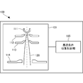
- the electron gun 100 is a device that supplies an electron beam.
- the electron gun 100 includes an electron beam supply unit 101 and an optimum condition collection control unit 105.
- the electron beam supply unit 101 includes a cathode 111, a Wehnelt electrode 112, a control electrode 113, and an anode 114.
- the cathode 111 emits thermoelectrons.
- the Wehnelt electrode 112 focuses thermoelectrons.
- the control electrode 113 controls the electric field strength at the tip of the cathode 111 and draws thermoelectrons from the tip of the cathode.
- the anode 114 accelerates the thermal electrons and irradiates the powder as an electron beam 120.
- the optimum condition collection control unit 105 changes the bias voltage applied to the Wehnelt electrode 112 and the control electrode voltage applied to the control electrode 113, thereby changing the bias voltage at which the luminance of the electron beam 120 forms a peak. And the control electrode voltage are determined.
- the emission current changes, it is possible to prevent a decrease in the brightness of the electron beam. Further, in order to prevent a decrease in the luminance of the electron beam, a combination of a bias voltage and a control voltage that form a peak in the luminance of the electron beam can be determined.
- FIG. 2 is a diagram for explaining the configuration of the electron gun 201 used in the three-dimensional modeling apparatus according to the prerequisite technology of the present embodiment.
- the electron gun 201 includes a cathode 211, a Wehnelt electrode 212, and an anode 214.
- the electron gun 201 is a three-electrode type electron gun. Since the electron gun 201 can easily obtain a large current, for example, a wide range of devices such as an electron microscope, an electron beam drawing device, an electron beam analyzer, an electron beam processing device (welding, surface modification, additive manufacturing, etc.), etc. Is used.
- the electron beam processing apparatus is generally provided with various processing modes, and the diameter of the electron beam 220 and the beam current of the electron beam 220 are rapidly changed according to the processing mode used or the usage situation. It is necessary to let Furthermore, since the electron beam of such an electron beam processing apparatus has a high acceleration voltage (several tens of kV or more) and a large current (10 mA or more), when the electron beam 220 is irradiated to the structure inside the apparatus, the structure There is a risk of damage.
- the current control diaphragm for controlling the beam current on the sample (on the powder) cannot be arranged in the electron optical column, the electrons emitted from the cathode 211 (electron gun 201) All of the beam 220 will reach the sample. That is, the beam current and emission current on the sample have the same value. In this case, in order to change the beam current, the emission current itself of the electron gun 201 must be changed.
- a method of changing the bias voltage (application voltage of the Wehnelt electrode 212) can be considered.
- the luminance of the electron beam 220 is changed in accordance with the change of the bias voltage. Also changes.
- the luminance is related to the size of the beam diameter of the electron beam 220 formed on the sample. That is, when the brightness of the electron beam 220 decreases, the beam diameter of the electron beam 220 increases.
- the luminance of the electron beam 220 is changed simultaneously with the change of the emission current like the electron gun 201, there is a problem that the luminance becomes small at a certain emission current and a desired beam diameter cannot be obtained.
- FIG. 3 is a diagram illustrating the configuration of the three-dimensional modeling apparatus 300 according to the present embodiment.
- FIG. 4 is a diagram illustrating the configuration of the electron gun 301 according to the present embodiment.
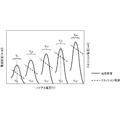
- FIG. 5 is a diagram illustrating a current signal curve acquired by beam scanning by the three-dimensional modeling apparatus 300 according to the present embodiment.
- the three-dimensional modeling apparatus 300 includes a lens barrel 360, a vacuum chamber 320, a high voltage power source 330, a computer 340, and an electron optical system control unit 350.
- the lens barrel 360 includes an electron gun 301, a lens 305, and a deflector 306.
- the electron gun 301 includes a cathode 311, a Wehnelt electrode 312, a control electrode 313, and an anode 314. That is, the electron gun 301 is a four-electrode type electron gun including four electrodes.
- the vacuum chamber 320 includes a Faraday cup 322, a cooling pipe 323, and an ammeter 324.
- the beam current and beam diameter of the electron beam 370 are measured using the Faraday cup 322.
- the Faraday cup 322 is provided with a cooling pipe 323 in order to suppress a temperature rise due to irradiation with the electron beam 370.
- the ammeter 324 measures the beam current 325 of the electron beam 370.
- the high voltage power supply 330 includes a cathode heating power supply 332, a bias power supply 334, a control electrode power supply 335, a power supply control unit 336, an ammeter 337, and an acceleration power supply 338.
- the ammeter 337 measures the load current 333.
- the computer 340 includes an optimum condition collection control unit 341 and an approximate calculation calculation unit 342.
- the electron optical system control unit 350 controls the electron optical system including the lens 305 and the deflector 306.
- the electron gun 301 is a thermionic emission type electron gun composed of four electrodes: a cathode 311, a Wehnelt electrode 312, a control electrode 313, and an anode 314.
- the electron gun 301 is operated by a cathode heating power source 332, a bias power source 334, a control electrode power source 335, and an acceleration power source 338 provided in the high voltage power source 330.
- the electron beam 370 emitted from the electron gun 301 is controlled by the lens 305 and the deflector 306 and focuses on the powder at a predetermined position.
- the three-dimensional modeling apparatus 300 adjusts the electron gun 301 by determining an optimum combination condition of a bias voltage and a control electrode voltage at which the luminance of the electron beam 370 forms a peak.
- a Faraday cup 322 with a knife edge provided in the vacuum chamber 320 is used.
- the Faraday cup 322 is provided with a cooling pipe 323 in order to suppress a temperature rise due to beam irradiation.
- a current signal curve as shown in FIG. 5 is measured.
- the apparatus used for measuring the beam current is not limited to this.
- the approximate calculation calculation unit 342 performs curve fitting and differential calculation processing on the acquired current signal curve to calculate the beam diameter of the electron beam 370.
- the beam current of the electron beam 370 reaching the sample surface (on the powder) may be obtained from the measured value of the Faraday cup 322, but is not limited thereto. Since the beam current of the electron beam 370 has the same value as the emission current emitted from the cathode 311 (electron gun 301), the load current 333 flowing through the high-voltage power source 330 can be measured by an ammeter 337.
- the series of operations described above are automatically performed by the optimum condition collection control unit 341 included in the computer 340.
- the optimum condition collection control unit 341 sends a command to the power supply control unit 336 to change the bias voltage and the control electrode voltage in a matrix.
- the optimum condition collection control unit 341 measures the beam diameter and beam current of the electron beam 370 by the method described above, calculates the current density under each condition, and controls the bias voltage and control for obtaining a specific emission current. Record optimum combination conditions with electrode voltage.
- the optimum condition collection control unit 341 also sends a command to the electron optical system control unit 350, and appropriately performs beam scanning of the electron beam 370 on the knife edge, focusing and defocusing of the electron beam 370, and the like.
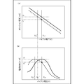
- FIG. 6 is a diagram showing the bias voltage characteristics of the current density and emission current of the electron gun 301 according to the present embodiment.
- FIG. 7 is another diagram showing the bias voltage characteristics of the current density and emission current of the electron gun 301 according to this embodiment.
- the control electrode voltage is fixed at V c1 , the beam diameter and beam current of the electron beam 370 are measured while changing the bias voltage, and the current density of the electron beam 370 is calculated. Thereby, the bias voltage characteristic between the current density and the emission current as shown in FIG. 6 is obtained. As shown in the figure, there is a bias voltage V b1 that maximizes the current density, and the emission current in this case is I 1 .
- This series of operations is performed while gradually increasing the control electrode voltage to V c2 , V c3 , V c4,. Thereby, a plurality of bias voltage characteristics of the current density and the emission current as shown in FIG. 7 are obtained, and an optimum combination condition of the bias voltage and the control electrode voltage with respect to the specific emission current is obtained.
- the acceleration voltage is constant in the three-electrode electron gun, only one bias voltage characteristic between the current density and the emission current can be obtained. In other words, in a three-electrode electron gun, when a large emission current is required, the brightness of the electron beam has to be reduced (since the brightness has been sacrificed), and the beam diameter has increased, resulting in high accuracy. It was not possible to make a high shape.
- Electron guns with a four-electrode configuration have the characteristic that the luminance hardly deteriorates (decreases) even if the emission current is changed. Therefore, electron beam machining such as a three-dimensional modeling apparatus that is assumed to be used while changing the emission current. An electron gun suitable for use in the apparatus. In other words, even if the emission current is changed, an electron beam with high brightness can be used correspondingly, and the beam diameter can be reduced by narrowing the electron beam, so that modeling (processing) with high accuracy is performed. Can do.
- the current density and the emission current must be acquired while changing the two parameters of the bias voltage and the control electrode voltage in a matrix. Therefore, manual data collection takes a lot of time.
- the optimum combination conditions change with the consumption of the cathode, the optimum combination conditions must be re-recorded each time the consumption of the cathode progresses to some extent.
- FIG. 8 is a flowchart for explaining the operation of the three-dimensional modeling apparatus 300 according to this embodiment.
- FIG. 9 is a diagram for explaining an outline of the determination of the cathode wear condition by the three-dimensional modeling apparatus 300 according to the present embodiment.
- the 3D modeling apparatus 300 automatically performs the determination of the degree of wear of the cathode 311 and the readjustment and fine adjustment of the bias voltage and the control electrode voltage according to this flowchart.
- step S801 the three-dimensional modeling apparatus 300 automatically adjusts the electron gun 301 so that an electron beam 370 suitable for manufacturing a modeled object by stacking powder is obtained. That is, the three-dimensional modeling apparatus 300 measures the emission current and the current density, and determines a plurality of conditions (optimum combination conditions) for the combination of the bias voltage and the control electrode voltage at which the luminance is the highest (forms a peak). To do. Then, the electron gun 301 applies a combination most suitable for the modeling conditions of the modeled object from the determined optimum combination conditions, and manufactures the modeled object. As a result, it is possible to always use the electron beam 370 having the highest luminance or peak luminance.
- step S803 the three-dimensional modeling apparatus 300 determines whether the apparatus is in an idling state. That is, the three-dimensional modeling apparatus 300 ends the operation if the apparatus is manufacturing a modeled object.
- the three-dimensional modeling apparatus 300 shifts to a determination mode in which the consumption state of the cathode 311 is determined in step S805. .
- step S 807 the emission current and the current density are measured again using the optimum combination condition derived in the automatic adjustment mode of the electron gun 301. .
- step S809 the three-dimensional modeling apparatus 300 determines whether or not the emission current remeasured in step S807 has decreased by 5% or more compared to the emission current obtained by the last adjustment of the electron gun 301.
- the emission current obtained at the end is compared, but the object of comparison is not limited to this.
- the emission current when the three-dimensional modeling apparatus 300 is first activated may be compared. Further, for example, due to the exhaustion of the cathode 311, it may be compared with an emission current immediately after the cathode 311 is replaced.
- the three-dimensional modeling apparatus 300 performs readjustment of the electron gun 301 in step S811. If the emission current has not decreased by 5% or more, the three-dimensional modeling apparatus 300 performs fine adjustment of the electron gun 301 in step S813.
- step S815 the three-dimensional modeling apparatus 300 changes the bias voltage and the control electrode voltage in a matrix and records the optimum combination condition from the beginning.
- the three-dimensional modeling apparatus 300 rerecords the optimum combination condition so that only the bias voltage is changed and a desired emission current is obtained in step S817.
- Determination of the degree of wear of the cathode 311 is performed when the apparatus is in an idling state (wait state).
- the optimum combination conditions (V b1 , V c1 ), (V b2 , V c2 ), (V b3 , V c3 ) recorded in the optimum condition collection control circuit 341 for the bias voltage and the control electrode voltage are: ⁇ Change the order in order to obtain the emission current and current density again.
- the tip of the cathode 311 Since the tip of the cathode 311 is consumed with use, the emission current becomes smaller than when the electron gun 311 is adjusted. Further, when the cathode 311 is consumed, the tip of the cathode 311 moves away from the Wehnelt electrode 312, so that the optimum bias voltage condition for each control electrode voltage is lower than the original condition.
- the optimum combination condition (V b1 , V c1 ) of the bias voltage and the control electrode voltage changes as shown in FIG. 9 as the cathode 311 is consumed.
- the solid line in the figure is a measurement result obtained when the bias voltage and the control electrode voltage are changed in a matrix when the electron gun 301 is adjusted.
- the points in the figure indicate the results measured by the cathode wear condition determination, and the broken lines indicate the results predicted from the data acquired by the cathode wear condition determination. If the bias voltage and the control electrode voltage are changed in a matrix, it takes time to acquire data. Therefore, in the cathode wear condition determination, the optimum combination condition (V b1 , V c1 ),... (V b5 , V Acquire data in c5 ).
- fine adjustment of the electron gun 301 is performed. To do.
- the fine adjustment of the electron gun 301 is an adjustment that changes only the bias voltage without changing the control electrode voltage when obtaining a desired emission current. For example, as shown in FIG. 9, the desired emission current I 1 was obtained under the optimum combination conditions (V b1 , V c1 ) when adjusting the electron gun, but only I 1 ′ was obtained as the cathode 311 was consumed. It is gone.
- the reduction in the emission current is compensated by changing the optimum combination condition from (V b1 , V c1 ) to (V b1 ′, V c1 ).
- the other optimum combination conditions V b2 , V c2 ), (V b3 , V c3 ),... (V b5 , V c5 ), (V b2 ′, V c2 ), (V b3 ′) , V c3 ),... (V b5 ′, V c5 ) and only the bias voltage are changed so that a desired emission current can be obtained under each condition.
- the optimum conditions (conditions in which current density and luminance show a peak (highest)) of the electron gun 301 change in a direction in which the bias voltage decreases. This change is the same as the direction in which the bias voltage is changed by fine adjustment of the electron gun 301.
- the electron gun adjustment not only compensates for the emission current, but also has the effect of bringing the electron gun setting closer to the optimum condition, although it is not perfect.
- “readjustment” of the electron gun 301 is performed.
- the readjustment of the electron gun 301 is an adjustment in which the optimum combination condition of the bias voltage and the control electrode voltage is obtained again from the beginning to obtain a desired emission current. If the emission current decreases greatly, even if the emission current can be compensated only by changing the bias voltage, it cannot be compensated until the current density is reduced.
- the brightness of the electron gun 301 is deteriorated (decreased) under each condition. Since the beam diameter cannot be reduced to a small value, the processing accuracy of the three-dimensional modeling apparatus 300 also decreases. Therefore, when the emission current is reduced by 5% or more in the cathode consumption condition determination, the electron gun 301 is readjusted.
- the four-electrode thermoelectron emission electron gun requires complicated adjustment of the electron gun. However, the provision of the above-described automatic adjustment mechanism makes it possible to always operate the electron gun with appropriate settings.
- the emission current drop of “5%” is used as a criterion for fine adjustment and readjustment, but the criterion is not limited to this. It is important to re-adjust the electron gun optimum condition that gradually moves away only by fine adjustment, and it becomes a determinant of the judgment criteria. As described here, when the emission current decrease of 5% is used as a criterion, readjustment of the electron gun 301 is performed before the luminance deviates much from the optimum condition.
- the emission current changes, it is possible to prevent a decrease in the brightness of the electron beam. Further, in order to prevent a decrease in the luminance of the electron beam, it is possible to determine an optimum condition for a combination of a bias voltage and a control voltage that keeps the luminance of the electron beam at the maximum luminance (peak luminance).
- the electron gun is described using a three-dimensional modeling apparatus.
- the use of the electron gun according to the present embodiment is not limited to this, and can be used for an electron microscope, for example.
- the present invention may be applied to a system composed of a plurality of devices, or may be applied to a single device. Furthermore, the present invention can also be applied to a case where an information processing program that implements the functions of the embodiments is supplied directly or remotely to a system or apparatus. Therefore, in order to realize the functions of the present invention on a computer, a program installed on the computer, a medium storing the program, and a WWW (World Wide Web) server that downloads the program are also included in the scope of the present invention. . In particular, at least a non-transitory computer readable medium storing a program for causing a computer to execute the processing steps included in the above-described embodiments is included in the scope of the present invention.
Abstract
Description
熱電子を放出するカソードと、
前記熱電子を集束するウェネルト電極と、
前記カソードの先端から前記熱電子を引き出す制御電極と、
前記熱電子を加速して、電子ビームとして粉体に照射するアノードと、
前記ウェネルト電極に印加するバイアス電圧および前記制御電極に印加する制御電極電圧の少なくともいずれか一方を変化させることにより、前記電子ビームの輝度がピークを形成する、前記バイアス電圧と前記制御電極電圧との組合せを決定する最適条件収集制御手段と、
を備えた。
電子銃のエミッション電流に基づいて、カソードの消耗具合を判定する判定ステップと、
前記エミッション電流の減少量が所定の閾値以上である場合には、前記電子銃のバイアス電圧および制御電極電圧の再調整を実行する再調整ステップと、
前記エミッション電流の減少量が前記所定の閾値未満である場合には、前記電子銃の前記バイアス電圧および制御電極電圧の微調整を実行する微調整ステップと、
を含むことを特徴とする。
電子銃のエミッション電流に基づいて、カソードの消耗具合を判定する判定ステップと、
前記エミッション電流の減少量が所定の閾値以上である場合には、前記電子銃のバイアス電圧および制御電極電圧の再調整を実行する再調整ステップと、
前記エミッション電流の減少量が前記所定の閾値未満である場合には、前記電子銃の前記バイアス電圧および制御電極電圧の微調整を実行する微調整ステップと、
をコンピュータに実行させることを特徴とする。
請求項1に記載の電子銃を用いた。
本発明の第1実施形態としての電子銃100について、図1を用いて説明する。電子銃100は、電子ビームを供給する装置である。
次に本発明の第2実施形態に係る3次元造形装置について、図2~図9を用いて説明する。
図2は、本実施形態の前提技術に係る3次元造形装置に用いられている電子銃201の構成を説明するための図である。電子銃201は、カソード211とウェネルト電極212とアノード214とを備えている。電子銃201は、3電極型の電子銃である。電子銃201は、容易に大電流を得ることができるので、例えば、電子顕微鏡や電子ビーム描画装置、電子ビーム分析装置、電子ビーム加工装置(溶接や表面改質、積層造形等)といった幅広い装置などに使用されている。
図3は、本実施形態に係る3次元造形装置300の構成を説明する図である。図4は、本実施形態に係る電子銃301の構成を説明する図である。図5は、本実施形態に係る3次元造形装置300によるビームスキャンにより取得した電流信号曲線を説明する図である。3次元造形装置300は、鏡筒360と真空チャンバ320と高圧電源330とコンピュータ340と電子光学系制御部350とを備える。
以上、実施形態を参照して本願発明を説明したが、本願発明は上記実施形態に限定されるものではない。本願発明の構成や詳細には、本願発明のスコープ内で当業者が理解し得る様々な変更をすることができる。また、それぞれの実施形態に含まれる別々の特徴を如何様に組み合わせたシステムまたは装置も、本発明の範疇に含まれる。
Claims (9)
- 熱電子を放出するカソードと、
前記熱電子を集束するウェネルト電極と、
前記カソードの先端から前記熱電子を引き出す制御電極と、
前記熱電子を加速して、電子ビームとして粉体に照射するアノードと、
前記ウェネルト電極に印加するバイアス電圧および前記制御電極に印加する制御電極電圧の少なくともいずれか一方を変化させることにより、前記電子ビームの輝度がピークを形成する、前記バイアス電圧と前記制御電極電圧との組合せを決定する最適条件収集制御手段と、
を備えた電子銃。 - 前記最適条件収集制御手段は、前記カソードと前記ウェネルト電極と前記制御電極と前記アノードとを備える電子銃のエミッション電流に基づいて、前記カソードの消耗具合を判定し、判定結果に基づいて、前記電子銃の前記バイアス電圧および前記制御電極電圧の微調整または再調整を実行することを特徴とする請求項1に記載の電子銃。
- 前記最適条件収集制御手段は、電子銃がアイドリング状態にある場合に、前記カソードの消耗具合の判定を実行することを特徴とする請求項1または2に記載の電子銃。
- 前記最適条件収集制御手段は、前記エミッション電流の減少量が、所定の閾値以上である場合には、前記再調整を実行し、前記所定の閾値未満である場合には、前記微調整を実行することを特徴とする請求項2または3に記載の電子銃。
- 前記最適条件収集制御手段は、所望のエミッション電流を得るために、前記バイアス電圧を変更して、前記微調整を実行することを特徴とする請求項2乃至4のいずれか1項に記載の電子銃。
- 前記最適条件収集制御手段は、所望のエミッション電流を得るために、前記バイアス電圧および前記制御電極電圧を変更して、前記再調整を実行することを特徴とする請求項2乃至4のいずれか1項に記載の電子銃。
- 電子銃のエミッション電流に基づいて、カソードの消耗具合を判定する判定ステップと、
前記エミッション電流の減少量が所定の閾値以上である場合には、前記電子銃のバイアス電圧および制御電極電圧の再調整を実行する再調整ステップと、
前記エミッション電流の減少量が前記所定の閾値未満である場合には、前記電子銃の前記バイアス電圧および制御電極電圧の微調整を実行する微調整ステップと、
を含むことを特徴とする電子銃の制御方法。 - 電子銃のエミッション電流に基づいて、カソードの消耗具合を判定する判定ステップと、
前記エミッション電流の減少量が所定の閾値以上である場合には、前記電子銃のバイアス電圧および制御電極電圧の再調整を実行する再調整ステップと、
前記エミッション電流の減少量が前記所定の閾値未満である場合には、前記電子銃の前記バイアス電圧および制御電極電圧の微調整を実行する微調整ステップと、
をコンピュータに実行させることを特徴とする電子銃の制御プログラム。 - 請求項1に記載の電子銃を用いた3次元造形装置。
Priority Applications (4)
| Application Number | Priority Date | Filing Date | Title |
|---|---|---|---|
| PCT/JP2015/050460 WO2016110996A1 (ja) | 2015-01-09 | 2015-01-09 | 電子銃、電子銃の制御方法および制御プログラム並びに3次元造形装置 |
| US14/785,730 US10217599B2 (en) | 2015-01-09 | 2015-01-09 | Electron gun, control method and control program thereof, and three-dimensional shaping apparatus |
| JP2016510533A JP6190040B2 (ja) | 2015-01-09 | 2015-01-09 | 電子銃、電子銃の制御方法および制御プログラム並びに3次元造形装置 |
| EP15778595.7A EP3065161B1 (en) | 2015-01-09 | 2015-01-09 | Electron gun, control method and control program thereof, and three-dimensional shaping apparatus |
Applications Claiming Priority (1)
| Application Number | Priority Date | Filing Date | Title |
|---|---|---|---|
| PCT/JP2015/050460 WO2016110996A1 (ja) | 2015-01-09 | 2015-01-09 | 電子銃、電子銃の制御方法および制御プログラム並びに3次元造形装置 |
Publications (1)
| Publication Number | Publication Date |
|---|---|
| WO2016110996A1 true WO2016110996A1 (ja) | 2016-07-14 |
Family
ID=56355717
Family Applications (1)
| Application Number | Title | Priority Date | Filing Date |
|---|---|---|---|
| PCT/JP2015/050460 WO2016110996A1 (ja) | 2015-01-09 | 2015-01-09 | 電子銃、電子銃の制御方法および制御プログラム並びに3次元造形装置 |
Country Status (4)
| Country | Link |
|---|---|
| US (1) | US10217599B2 (ja) |
| EP (1) | EP3065161B1 (ja) |
| JP (1) | JP6190040B2 (ja) |
| WO (1) | WO2016110996A1 (ja) |
Cited By (3)
| Publication number | Priority date | Publication date | Assignee | Title |
|---|---|---|---|---|
| JP2019053919A (ja) * | 2017-09-15 | 2019-04-04 | 日本電子株式会社 | 冷陰極電界放出型電子銃、冷陰極電界放出型電子銃の調整方法、エミッタの先鋭化方法、および電子顕微鏡 |
| JP2020004557A (ja) * | 2018-06-27 | 2020-01-09 | 株式会社日立製作所 | 電子顕微鏡 |
| JP2021502670A (ja) * | 2017-11-10 | 2021-01-28 | ア−カム アーベー | フィラメントの疲労を検出する方法、3次元物品を形成する方法、およびフィラメントの疲労を検出するデバイス |
Families Citing this family (11)
| Publication number | Priority date | Publication date | Assignee | Title |
|---|---|---|---|---|
| JP6437316B2 (ja) * | 2014-02-14 | 2018-12-12 | 日本電子株式会社 | 電子銃、三次元積層造形装置及び電子銃制御方法 |
| KR20180061136A (ko) * | 2015-06-19 | 2018-06-07 | 어플라이드 머티어리얼스, 인코포레이티드 | 적층 제조에서의 파우더의 선택적 퇴적 |
| US11569064B2 (en) | 2017-09-18 | 2023-01-31 | Ims Nanofabrication Gmbh | Method for irradiating a target using restricted placement grids |
| JP7007152B2 (ja) * | 2017-10-19 | 2022-01-24 | 株式会社アドバンテスト | 三次元積層造形装置および積層造形方法 |
| US10651010B2 (en) | 2018-01-09 | 2020-05-12 | Ims Nanofabrication Gmbh | Non-linear dose- and blur-dependent edge placement correction |
| US10840054B2 (en) * | 2018-01-30 | 2020-11-17 | Ims Nanofabrication Gmbh | Charged-particle source and method for cleaning a charged-particle source using back-sputtering |
| EP3613563A1 (en) * | 2018-08-24 | 2020-02-26 | Concept Laser GmbH | Apparatus for additively manufacturing at least one three-dimensional object |
| US11099482B2 (en) | 2019-05-03 | 2021-08-24 | Ims Nanofabrication Gmbh | Adapting the duration of exposure slots in multi-beam writers |
| KR20210132599A (ko) | 2020-04-24 | 2021-11-04 | 아이엠에스 나노패브릭케이션 게엠베하 | 대전 입자 소스 |
| JP7160857B2 (ja) * | 2020-05-20 | 2022-10-25 | 日本電子株式会社 | ビーム調整方法及び三次元積層造形装置 |
| EP4325545A1 (en) * | 2022-08-19 | 2024-02-21 | incoatec GmbH | X-ray tube with flexible intensity adjustment |
Citations (3)
| Publication number | Priority date | Publication date | Assignee | Title |
|---|---|---|---|---|
| JPH01274349A (ja) | 1988-04-25 | 1989-11-02 | Jeol Ltd | 電子銃用高圧電源 |
| JP2000011932A (ja) * | 1998-06-18 | 2000-01-14 | Advantest Corp | 電子銃 |
| JP2010261072A (ja) * | 2009-05-07 | 2010-11-18 | Htl:Kk | 電子ビーム造形方法 |
Family Cites Families (12)
| Publication number | Priority date | Publication date | Assignee | Title |
|---|---|---|---|---|
| JPS56133824A (en) * | 1980-03-21 | 1981-10-20 | Toshiba Corp | Electron beam device |
| JPS57165943A (en) * | 1981-04-02 | 1982-10-13 | Akashi Seisakusho Co Ltd | Acceleration controlling method for charged particle beams in electron microscope and similar device |
| JPS5818833A (ja) * | 1981-07-27 | 1983-02-03 | Denki Kagaku Kogyo Kk | 高密度電子ビ−ムの低温発生方法及びその装置 |
| JPS58223247A (ja) * | 1982-06-22 | 1983-12-24 | Toshiba Corp | 電子銃の輝度設定方法 |
| JPS63216261A (ja) * | 1987-03-02 | 1988-09-08 | Jeol Ltd | 集束イオンビ−ム装置等のビ−ム電流安定化装置 |
| JP3418941B2 (ja) * | 1992-03-30 | 2003-06-23 | 日本電子株式会社 | 電子線発生装置 |
| US5834781A (en) * | 1996-02-14 | 1998-11-10 | Hitachi, Ltd. | Electron source and electron beam-emitting apparatus equipped with same |
| US6590216B1 (en) * | 2000-01-27 | 2003-07-08 | Nikon Corporation | Servo control for high emittance electron source |
| JP3943022B2 (ja) | 2000-12-01 | 2007-07-11 | 株式会社荏原製作所 | 基板検査装置 |
| US8487534B2 (en) * | 2010-03-31 | 2013-07-16 | General Electric Company | Pierce gun and method of controlling thereof |
| US9079248B2 (en) * | 2011-12-28 | 2015-07-14 | Arcam Ab | Method and apparatus for increasing the resolution in additively manufactured three-dimensional articles |
| US8779376B2 (en) * | 2012-01-09 | 2014-07-15 | Fei Company | Determination of emission parameters from field emission sources |
-
2015
- 2015-01-09 EP EP15778595.7A patent/EP3065161B1/en not_active Not-in-force
- 2015-01-09 JP JP2016510533A patent/JP6190040B2/ja active Active
- 2015-01-09 US US14/785,730 patent/US10217599B2/en not_active Expired - Fee Related
- 2015-01-09 WO PCT/JP2015/050460 patent/WO2016110996A1/ja active Application Filing
Patent Citations (3)
| Publication number | Priority date | Publication date | Assignee | Title |
|---|---|---|---|---|
| JPH01274349A (ja) | 1988-04-25 | 1989-11-02 | Jeol Ltd | 電子銃用高圧電源 |
| JP2000011932A (ja) * | 1998-06-18 | 2000-01-14 | Advantest Corp | 電子銃 |
| JP2010261072A (ja) * | 2009-05-07 | 2010-11-18 | Htl:Kk | 電子ビーム造形方法 |
Non-Patent Citations (1)
| Title |
|---|
| See also references of EP3065161A4 |
Cited By (4)
| Publication number | Priority date | Publication date | Assignee | Title |
|---|---|---|---|---|
| JP2019053919A (ja) * | 2017-09-15 | 2019-04-04 | 日本電子株式会社 | 冷陰極電界放出型電子銃、冷陰極電界放出型電子銃の調整方法、エミッタの先鋭化方法、および電子顕微鏡 |
| JP2021502670A (ja) * | 2017-11-10 | 2021-01-28 | ア−カム アーベー | フィラメントの疲労を検出する方法、3次元物品を形成する方法、およびフィラメントの疲労を検出するデバイス |
| JP2020004557A (ja) * | 2018-06-27 | 2020-01-09 | 株式会社日立製作所 | 電子顕微鏡 |
| JP7068069B2 (ja) | 2018-06-27 | 2022-05-16 | 株式会社日立製作所 | 電子顕微鏡 |
Also Published As
| Publication number | Publication date |
|---|---|
| EP3065161A1 (en) | 2016-09-07 |
| JP6190040B2 (ja) | 2017-08-30 |
| EP3065161A4 (en) | 2017-08-02 |
| US20170154750A1 (en) | 2017-06-01 |
| EP3065161B1 (en) | 2018-11-21 |
| JPWO2016110996A1 (ja) | 2017-04-27 |
| US10217599B2 (en) | 2019-02-26 |
Similar Documents
| Publication | Publication Date | Title |
|---|---|---|
| JP6190040B2 (ja) | 電子銃、電子銃の制御方法および制御プログラム並びに3次元造形装置 | |
| US9257257B2 (en) | Electron beam control method, electron beam generating apparatus, apparatus using the same, and emitter | |
| JP5290238B2 (ja) | 電子顕微鏡 | |
| KR101570362B1 (ko) | 캐소드의 동작 온도 조정 방법 및 전자빔 묘화 장치 | |
| JP2020087930A (ja) | 電子銃、電子放出装置、及び電子銃の製造方法 | |
| CN113793790A (zh) | 开放式微焦点x射线源及其控制方法 | |
| JP2016152251A (ja) | 電子ビーム描画装置のカソードの寿命予測方法 | |
| JP6943701B2 (ja) | 冷陰極電界放出型電子銃の調整方法 | |
| JP5362297B2 (ja) | 荷電粒子ビーム描画装置および荷電粒子ビーム描画方法 | |
| JP2008251300A (ja) | X線検査装置 | |
| KR101648063B1 (ko) | X선 발생장치 및 그 제어방법 | |
| JP2012018790A (ja) | 電子銃の駆動方法、電子ビーム描画装置および電子ビーム描画方法 | |
| JP4676461B2 (ja) | 電子ビーム描画装置及び電子ビームの電流密度調整方法 | |
| JP6129982B2 (ja) | 電子顕微鏡 | |
| JP2018098395A (ja) | 荷電粒子装置、荷電粒子描画装置および荷電粒子ビーム制御方法 | |
| WO2020161795A1 (ja) | 荷電粒子線装置 | |
| US11398364B2 (en) | Electron gun, electron microscope, three-dimensional additive manufacturing apparatus, and method of adjusting current of electron gun | |
| US20190304743A1 (en) | Charged particle beam system and method | |
| US11404238B2 (en) | Control method for electron microscope and electron microscope | |
| JP6246647B2 (ja) | 電子銃、三次元積層造形装置及び電子銃制御方法 | |
| US11749491B2 (en) | Electron beam writing apparatus and cathode life span prediction method | |
| JP6118142B2 (ja) | 電子銃装置、描画装置、電子銃電源回路のリーク電流測定方法、及び電子銃電源回路のリーク電流判定方法 | |
| WO2023067681A1 (ja) | 荷電粒子線装置 | |
| JP7068069B2 (ja) | 電子顕微鏡 | |
| JP2014056743A (ja) | X線発生装置 |
Legal Events
| Date | Code | Title | Description |
|---|---|---|---|
| WWE | Wipo information: entry into national phase |
Ref document number: 14785730 Country of ref document: US |
|
| REEP | Request for entry into the european phase |
Ref document number: 2015778595 Country of ref document: EP |
|
| WWE | Wipo information: entry into national phase |
Ref document number: 2015778595 Country of ref document: EP |
|
| ENP | Entry into the national phase |
Ref document number: 2016510533 Country of ref document: JP Kind code of ref document: A |
|
| 121 | Ep: the epo has been informed by wipo that ep was designated in this application |
Ref document number: 15778595 Country of ref document: EP Kind code of ref document: A1 |
|
| NENP | Non-entry into the national phase |
Ref country code: DE |