WO2016106622A1 - 移动物体及其天线自动对准方法、系统 - Google Patents
移动物体及其天线自动对准方法、系统 Download PDFInfo
- Publication number
- WO2016106622A1 WO2016106622A1 PCT/CN2014/095757 CN2014095757W WO2016106622A1 WO 2016106622 A1 WO2016106622 A1 WO 2016106622A1 CN 2014095757 W CN2014095757 W CN 2014095757W WO 2016106622 A1 WO2016106622 A1 WO 2016106622A1
- Authority
- WO
- WIPO (PCT)
- Prior art keywords
- antenna
- current
- antennas
- moving object
- wireless terminal
- Prior art date
- Legal status (The legal status is an assumption and is not a legal conclusion. Google has not performed a legal analysis and makes no representation as to the accuracy of the status listed.)
- Ceased
Links
Images




Classifications
-
- H—ELECTRICITY
- H04—ELECTRIC COMMUNICATION TECHNIQUE
- H04B—TRANSMISSION
- H04B7/00—Radio transmission systems, i.e. using radiation field
- H04B7/02—Diversity systems; Multi-antenna system, i.e. transmission or reception using multiple antennas
- H04B7/04—Diversity systems; Multi-antenna system, i.e. transmission or reception using multiple antennas using two or more spaced independent antennas
- H04B7/06—Diversity systems; Multi-antenna system, i.e. transmission or reception using multiple antennas using two or more spaced independent antennas at the transmitting station
- H04B7/0602—Diversity systems; Multi-antenna system, i.e. transmission or reception using multiple antennas using two or more spaced independent antennas at the transmitting station using antenna switching
- H04B7/0608—Antenna selection according to transmission parameters
-
- G—PHYSICS
- G05—CONTROLLING; REGULATING
- G05D—SYSTEMS FOR CONTROLLING OR REGULATING NON-ELECTRIC VARIABLES
- G05D3/00—Control of position or direction
- G05D3/12—Control of position or direction using feedback
-
- G—PHYSICS
- G01—MEASURING; TESTING
- G01C—MEASURING DISTANCES, LEVELS OR BEARINGS; SURVEYING; NAVIGATION; GYROSCOPIC INSTRUMENTS; PHOTOGRAMMETRY OR VIDEOGRAMMETRY
- G01C17/00—Compasses; Devices for ascertaining true or magnetic north for navigation or surveying purposes
- G01C17/02—Magnetic compasses
- G01C17/28—Electromagnetic compasses
- G01C17/32—Electron compasses
-
- G—PHYSICS
- G01—MEASURING; TESTING
- G01S—RADIO DIRECTION-FINDING; RADIO NAVIGATION; DETERMINING DISTANCE OR VELOCITY BY USE OF RADIO WAVES; LOCATING OR PRESENCE-DETECTING BY USE OF THE REFLECTION OR RERADIATION OF RADIO WAVES; ANALOGOUS ARRANGEMENTS USING OTHER WAVES
- G01S19/00—Satellite radio beacon positioning systems; Determining position, velocity or attitude using signals transmitted by such systems
- G01S19/01—Satellite radio beacon positioning systems transmitting time-stamped messages, e.g. GPS [Global Positioning System], GLONASS [Global Orbiting Navigation Satellite System] or GALILEO
- G01S19/13—Receivers
-
- H—ELECTRICITY
- H04—ELECTRIC COMMUNICATION TECHNIQUE
- H04B—TRANSMISSION
- H04B7/00—Radio transmission systems, i.e. using radiation field
- H04B7/02—Diversity systems; Multi-antenna system, i.e. transmission or reception using multiple antennas
- H04B7/04—Diversity systems; Multi-antenna system, i.e. transmission or reception using multiple antennas using two or more spaced independent antennas
- H04B7/08—Diversity systems; Multi-antenna system, i.e. transmission or reception using multiple antennas using two or more spaced independent antennas at the receiving station
- H04B7/0802—Diversity systems; Multi-antenna system, i.e. transmission or reception using multiple antennas using two or more spaced independent antennas at the receiving station using antenna selection
-
- H—ELECTRICITY
- H04—ELECTRIC COMMUNICATION TECHNIQUE
- H04L—TRANSMISSION OF DIGITAL INFORMATION, e.g. TELEGRAPHIC COMMUNICATION
- H04L69/00—Network arrangements, protocols or services independent of the application payload and not provided for in the other groups of this subclass
- H04L69/24—Negotiation of communication capabilities
-
- B—PERFORMING OPERATIONS; TRANSPORTING
- B64—AIRCRAFT; AVIATION; COSMONAUTICS
- B64U—UNMANNED AERIAL VEHICLES [UAV]; EQUIPMENT THEREFOR
- B64U2201/00—UAVs characterised by their flight controls
-
- B—PERFORMING OPERATIONS; TRANSPORTING
- B64—AIRCRAFT; AVIATION; COSMONAUTICS
- B64U—UNMANNED AERIAL VEHICLES [UAV]; EQUIPMENT THEREFOR
- B64U2201/00—UAVs characterised by their flight controls
- B64U2201/20—Remote controls
-
- H—ELECTRICITY
- H04—ELECTRIC COMMUNICATION TECHNIQUE
- H04W—WIRELESS COMMUNICATION NETWORKS
- H04W4/00—Services specially adapted for wireless communication networks; Facilities therefor
- H04W4/20—Services signaling; Auxiliary data signalling, i.e. transmitting data via a non-traffic channel
- H04W4/21—Services signaling; Auxiliary data signalling, i.e. transmitting data via a non-traffic channel for social networking applications
-
- H—ELECTRICITY
- H04—ELECTRIC COMMUNICATION TECHNIQUE
- H04W—WIRELESS COMMUNICATION NETWORKS
- H04W4/00—Services specially adapted for wireless communication networks; Facilities therefor
- H04W4/80—Services using short range communication, e.g. near-field communication [NFC], radio-frequency identification [RFID] or low energy communication
Definitions
- the present invention relates to an antenna alignment method, and in particular, to a moving object and an antenna automatic alignment method and system thereof.
- the control and data transmission of the existing universal commercial UAV is mainly a point-to-point transmission method, which is divided into a ground end and an aircraft end.
- the ground end mainly completes the remote control aircraft, receives the data returned by the flight end and performs processing, etc., while the aircraft end mainly performs flight according to the ground end command, and sends corresponding data to the ground end according to the command of the ground end.
- the ground end and the aircraft end form a point-to-point communication link.
- the stability and reliability of the communication link play an important role in the safe and controllable flight of the aircraft and data backhaul.
- the transmission power and receiving sensitivity will remain basically the same, and the stability is relatively high.
- the actual relative gain of the transceiver antenna will vary with the relative position and orientation between the two. Then, from the calculation formula of the above system gain GSYS, it can be seen that to maintain the stability of the system gain, it is necessary to ensure that the transmitting and receiving antennas are in the direction of the maximum gain of the other party.
- the servo pan/tilt is usually used to dynamically adjust the position of the antenna according to the orientation of the other party or the strength of the received signal.
- Patents are also available at home and abroad.
- the patent number is CN 202257283 U.
- the invention is entitled "A Automatic Tracking Antenna Device and Mobile Terminal" Chinese Patent.
- This Chinese patent automatically aligns satellite-like GPS antennas with satellites based on servo heads and electronic compasses.
- the structure of the Chinese patented automatic tracking antenna device is relatively complicated and large in size, and is not suitable for wireless communication in the field of unmanned aerial vehicles.
- An antenna automatic alignment method for a mobile object comprising a plurality of antennas for establishing a communication link with a wireless terminal, the method comprising the steps of:
- the multiple antennas including a backup antenna
- An antenna that can be used for current communication is selected based on current feature information of the plurality of antennas.
- the antenna automatic alignment method a plurality of antennas including a spare antenna are disposed on a moving object, and the antenna for communication is switched by the current feature information of the plurality of antennas acquired in real time, and the transmitting and receiving antennas are always blocked. Maintain communication stability and reliability.
- the present invention also provides an antenna automatic alignment system based on the above antenna automatic alignment method.
- An antenna automatic alignment system for a moving object characterized in that the moving object comprises a plurality of antennas for establishing a communication link with a wireless terminal, the antenna automatic alignment system comprising:
- a feature information acquiring module configured to acquire current feature information of the multiple antennas in real time, where the multiple antennas include a backup antenna;
- An antenna selection module is configured to select an antenna that can be used for current communication according to current feature information of the multiple antennas.
- the present invention also provides a moving object to which the above-described antenna automatic alignment method is applied.
- a moving object including:
- the plurality of antennas for establishing a communication link with the wireless terminal, the plurality of antennas including a backup antenna;
- a feature information acquiring device configured to acquire current feature information of the multiple antennas in real time
- the controller is communicably connected to the plurality of antennas and the feature information acquiring device, and is configured to select an antenna that can be used for current communication according to current feature information of the plurality of antennas.
- the present invention further provides a controller for performing the steps of calculation, judgment, selection, and the like in the above-described antenna automatic alignment method.
- FIG. 1 is a schematic diagram of an antenna automatic alignment method according to an embodiment of the present invention.
- FIG. 2 is a schematic diagram of the principle of the automatic alignment method of the antenna shown in FIG. 1;
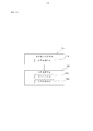
- FIG. 3 is a flowchart of an antenna automatic alignment method according to Embodiment 1 of the present invention.
- step S1a of the antenna automatic alignment method shown in FIG. 3 is a flow chart of one embodiment of step S1a of the antenna automatic alignment method shown in FIG. 3;
- FIG. 5 is a flow chart showing another embodiment of the step S1a of the antenna automatic alignment method shown in Figure 3;
- step S2a of the antenna automatic alignment method shown in FIG. 3 is a flow chart of one embodiment of step S2a of the antenna automatic alignment method shown in FIG. 3;
- FIG. 7 is a specific flowchart of the antenna automatic alignment method shown in FIG. 6;
- FIG. 9 is a flowchart of one embodiment of a first step of an antenna automatic alignment method according to Embodiment 2 of the present invention.
- Figure 10 is a flow chart showing another embodiment of the first step of the antenna automatic alignment method shown in Figure 9;
- FIG. 11 is a flowchart of one embodiment of a second step of an automatic antenna alignment method according to Embodiment 2 of the present invention.
- Figure 13 is a block diagram of an antenna automatic alignment system according to Embodiment 1 of the present invention.
- FIG. 14 is a block diagram of one embodiment of a feature information acquisition module of the antenna automatic alignment system shown in FIG. 13;
- FIG. 15 is a block diagram of one embodiment of an antenna selection module of the antenna automatic alignment system shown in FIG. 13;
- FIG. 16 is a specific block diagram of an antenna selection module of an antenna automatic alignment system according to Embodiment 2 of the present invention.
- FIG. 17 is a specific block diagram of an antenna automatic alignment system according to Embodiment 3 of the present invention.
- Figure 18 is a circuit schematic diagram of a moving object according to an embodiment of the present invention.
- Figure 19 is a circuit schematic diagram of a mobile terminal communicatively coupled to the mobile object shown in Figure 18.
- Embodiments of the present invention provide an antenna automatic alignment method for a mobile object, the mobile object including a plurality of antennas for establishing a communication link with a wireless terminal, the plurality of antennas including a backup antenna.
- the method acquires current feature information of the multiple antennas in real time, and selects an antenna that can be used for current communication according to current feature information of the multiple antennas. For example, according to current feature information of the plurality of antennas, an antenna that is currently aligned with the wireless terminal can be selected and used as an antenna for current communication.
- the moving object may be a ground moving object, such as a ground remotely controlled vehicle, etc.; or an object may be moved in the air, such as an unmanned aerial vehicle or the like.
- Unmanned aerial vehicles can be fixed-wing drones, rotary-wing drones, and the like.
- the wireless terminal may be a terrestrial wireless terminal, for example, a UAV ground base station, a remote controller, etc., or may be an over-the-air wireless terminal, such as a UAV air base station, other aircraft, or the like.
- the antenna may be a WiFi antenna, a WiMAX antenna, a COFDM antenna, or the like.
- the current feature information may be signal state information of the antenna, for example, signal power of the antenna, signal strength of the antenna, signal quality of the antenna, etc., may also be Relative position information of the antenna with respect to the wireless terminal, for example, current position information of the plurality of antennas with respect to the moving object, current position information of the wireless terminal with respect to the moving object, and the like.
- the present invention also provides an antenna alignment system for a moving object.
- the present invention also provides a moving object based on the above antenna automatic alignment method.
- the moving object includes: feature information acquiring means for acquiring current feature information of the plurality of antennas in real time, communicably connected to the wireless circuit module and the feature information acquiring device, and configured to be used according to the plurality of antennas
- the current feature information selects a controller that can be used for the antenna of the current communication.
- the feature information acquiring apparatus includes at least one of: an attitude sensor for acquiring current posture information of the moving object, for acquiring the current absolute of the moving object or/and the mobile terminal in real time.
- a position sensor for position information a wireless circuit module for scanning signal power of the plurality of antennas.
- an antenna automatic alignment method according to Embodiment 1 of the present invention is applied to a moving object 10, which includes a plurality of antennas 11 for establishing a communication link with the wireless terminal 20.
- the moving object 10 may be an air moving object, a ground moving object, or the like.
- the wireless terminal 20 may be a terrestrial wireless terminal, an over-the-air wireless terminal, etc., and the antenna 11 may be a WiFi antenna, a WiMAX antenna, a COFDM antenna, or the like.
- the mobile object 10 is described by taking an unmanned aerial vehicle as an example.
- the wireless terminal 20 is described by taking a remote controller as an example, and the communication link is exemplified by a MIMO communication link.
- the antenna automatic alignment method includes steps S1a to S2a.
- step S1a current feature information of the plurality of antennas 11 is acquired in real time, and the plurality of antennas 11 include spare antennas.
- the current feature information includes at least one of signal state information of the antenna 11 and relative position information of the antenna 11 with respect to the wireless terminal 20.
- the current feature information may include current location information of the plurality of antennas 11 with respect to the mobile object 10, current location information of the wireless terminal 20 with respect to the mobile object 10, and the like.
- the signal state information may be the signal power of the antenna 11, the signal strength of the antenna 11, the signal quality of the antenna 11, and the like.
- the current feature information is relative position information of the plurality of antennas 11 with respect to the wireless terminal 20, which may include current position information of the plurality of antennas 11 with respect to the moving object 10, and the wireless terminal 20 Relative position information relative to the moving object 10.
- step S1a specifically includes the following steps:
- step S11a the current posture information of the moving object 10 and the preset posture information of the plurality of antennas 11 with respect to the moving object 10 are acquired.
- the angle between the north direction and the nose is a heading angle ⁇ , wherein the clockwise direction is positive and the counterclockwise direction is negative.
- the angle ⁇ ranges from -180° to 180°.
- the unmanned aerial vehicle is used as the coordinate system, that is, the X-axis is connected to the tail of the nose, and the horizontal coordinate system (not shown) is established for the left and right sides of the UAV.
- the four sets of antennas 11 on the unmanned aerial vehicle are respectively A1 ⁇ A4, and ⁇ 1, ⁇ 2, ⁇ 3, and ⁇ 4 are the horizontal angles of the four antennas A1 ⁇ A4 on the unmanned aerial vehicle and the head direction of the unmanned aerial vehicle, respectively.
- the four antennas A1 to A4 are respectively mounted on the four corners of the unmanned aircraft at 45°, 135°, 225°, and 315°. Since the four antennas A1 ⁇ A4 are located at the four corners of the unmanned aerial vehicle, it is ensured that the unmanned aircraft always has two antennas 11 not blocked by the fuselage regardless of the posture and heading, and the wireless terminal 20 Form line of sight communication.
- step S12a based on the current posture information of the moving object 10 and the preset posture information of the plurality of antennas 11 with respect to the moving object 10, the current position information of the plurality of antennas 11 with respect to the moving object 10 is calculated.
- the geometric center of the unmanned aerial vehicle is taken as the origin
- the north-south direction is the X-axis (the north is the forward direction)
- the east-west direction is the Y-axis (the west is the forward direction) to establish the coordinate system.
- the position of the four antennas A1 ⁇ A4 of the UAV and the position of the wireless terminal 20 are equivalent to four vector points on the plane coordinate system.
- the angles between the four antennas A1 to A4 and the X axis are ⁇ + ⁇ 1, ⁇ + ⁇ 2, ⁇ + ⁇ 3 and ⁇ + ⁇ 4, respectively.
- the step S1a specifically includes:
- step S13a the current absolute position information of the wireless terminal 20 and the current absolute position information of the moving object 10 are acquired in real time.
- the absolute position of the wireless terminal 20 is Gp, and the absolute position of the wireless terminal 20 is Up, and their absolute positions are acquired by the positioning sensor.
- Step S14a based on the current absolute position information of the wireless terminal 20 and the current absolute position information of the moving object 10, the current position information of the wireless terminal 20 with respect to the moving object 10 is calculated.
- the wireless terminal is taken as the origin of the geometric center of the unmanned aerial vehicle, the north-south direction is the X-axis (the north is the forward direction), and the east-west direction is the Y-axis (the west is the forward direction).
- the position vector is at an angle ⁇ with the X axis.
- the step S1a specifically includes:
- Step S13'a acquiring current absolute position information of the moving object 10 in real time
- Step S14'a based on the position information of the starting point of the moving object 10 and the current absolute position information of the moving object 10, the current position information of the wireless terminal 20 with respect to the moving object 10 is calculated.
- the starting point of the moving object 10 is the take-off point of the unmanned aerial vehicle.
- step S2a the antenna 11 that can be used for the current communication is selected based on the current feature information of the plurality of antennas 11.
- step S2a specifically includes:
- step S21 it is calculated whether the current feature information of the plurality of antennas 11 satisfies a switching criterion.
- the switching criterion includes at least one of: selecting an antenna 11 having a larger value of current feature information among the plurality of antennas 11, selecting an antenna 11 having a smaller value of current feature information among the plurality of antennas 11, and selecting a plurality of antennas 11 The current feature information satisfies the antenna 11 of a threshold range.
- Each current feature information corresponds to a switching criterion, or multiple current feature information corresponds to the same switching criterion. It is calculated whether the current feature information of the plurality of antennas 11 satisfies the corresponding switching criterion.
- the switching criterion may be set according to a rule of the plurality of antennas 11 that aligns with the current feature information of the antenna 11 of the wireless terminal 20.
- step S22 according to the switching criterion, the antenna 11 that can be used for the current communication is selected.
- the antenna 11 whose current feature information satisfies the corresponding switching criterion is selected as the current communication antenna.
- the current feature information is relative position information of the plurality of antennas 11 with respect to the wireless terminal 20, which may include current position information of the plurality of antennas 11 with respect to the moving object 10, and the wireless terminal 20 is relative to the moving object 10 Current location information.
- step S2a specifically includes:
- step S21a it is calculated whether the current position information of the plurality of antennas 11 with respect to the moving object 10 and the current position information of the wireless terminal 20 with respect to the moving object 10 satisfy a switching criterion.
- the step S21a specifically includes:
- step S211a a plurality of position ranges are constructed based on the current position information of the plurality of antennas 11 with respect to the moving object.
- four threshold ranges are constructed based on the current angular positions ⁇ + ⁇ 1, ⁇ + ⁇ 2, ⁇ + ⁇ 3, and ⁇ + ⁇ 4 of the four antennas A1 to A4 with respect to the UAV. +360) mod 360, ( ⁇ + ⁇ 2 + 360) mod 360, ( ⁇ + ⁇ 3 + 360) mod 360, ( ⁇ + ⁇ 4 + 360) mod 360, where mod is a remainder function.
- Step S212a calculating whether the plurality of location ranges cover the current location information of the wireless terminal 20 with respect to the mobile object 10.
- the switching criterion is: an antenna 11 corresponding to a range of locations of the wireless terminal 20 with respect to current location information of the mobile object 10, that is, an antenna 11 that is aligned with the wireless terminal 20.
- the relative angle ⁇ of the wireless terminal relative to the moving object 10 is calculated to fall within four threshold ranges ( ⁇ + ⁇ 1 + 360) mod 360, ( ⁇ + ⁇ 2 + 360) mod 360, ( ⁇ + ⁇ 3+360) mod 360, which of ( ⁇ + ⁇ 4 + 360) mod 360.
- step S22a the antenna 11 that can be used for the current communication is selected according to the switching criterion.
- step S22a specifically includes:
- step S221a one of the antennas 11 corresponding to the range of positions covering the current position information of the wireless terminal 20 with respect to the moving object 10 is selected as the antenna 11 for aligning the wireless terminal 20.
- the location range includes a coordinate range in which the current position information of the plurality of antennas 11 with respect to the moving object 10 is an end point and a preset protection range.
- the preset protection range is for preventing the plurality of antennas 11 from frequently switching at the coordinate positions of the end points of the antennas, which easily causes communication interruption.
- the dead zone protection angle ⁇ is 10°, when the above angle exceeds the dead zone protection angle The antenna is switched afterwards.
- antennas A1 and A2 are used. Then, with the movement of the aircraft, at the next moment, the relationship between the heading angle ⁇ and the relative angle ⁇ is as follows:
- the antennas A1 and A2 are still used, and only when ( ⁇ + ⁇ 2 + 360) mod 360 + ⁇ ⁇ ⁇ ⁇ ( ⁇ + ⁇ 3 + 360) mod 360, the antennas A2 and A3 are switched.
- the relative angle ⁇ angle of the wireless terminal 20 and the UAV and the heading angle ⁇ are calculated according to a certain time interval t, and then the corresponding antenna 11 is switched according to the calculation result.
- the determination of the time interval t is comprehensively determined according to the time slot allocation scheme of the wireless terminal 20 and the unmanned aerial vehicle, the position refresh rate of the positioning sensor, and the change of the posture of the unmanned aerial vehicle.
- the switching time of the antenna 11 cannot fall in the time slot of the wireless communication data transmission and reception, otherwise the communication error will be caused.
- the installation mode and switching mechanism of the antenna 11 are similar to those described above.
- the arrangement interval angle between the antennas 11 can be changed to 360°/N, and the switching antennas 11 are combined into N groups.
- the antenna automatic alignment method in the second embodiment of the present invention is substantially the same as the first embodiment, and the difference is that the current feature information in the antenna automatic alignment method in the second embodiment is the current location information of the plurality of antennas 11, And location information of the wireless terminal 20.
- the step of acquiring the current feature information of the multiple antennas 11 with respect to the wireless terminal 20 includes:
- step S11b the current posture information of the moving object 10 and the preset posture information of the plurality of antennas 11 with respect to the moving object 10 are acquired.
- step S12b based on the current posture information of the moving object 10 and the preset posture information of the plurality of antennas 11 with respect to the moving object 10, the current position information of the plurality of antennas 11 with respect to the moving object 10 is calculated.
- the wireless terminal 20 when the current location information of the wireless terminal 20 can be obtained in real time, for example, the wireless terminal 20 is provided with a positioning sensor such as a GPS, and the current location information of the wireless terminal 20 is acquired in real time by the positioning sensor of the moving object 10, and the step S1b specifically includes :
- step S13b the current absolute position information of the wireless terminal 20 and the current absolute position information of the moving object 10 are acquired in real time.
- Step S14b based on the current absolute position information of the wireless terminal 20 and the current absolute position information of the moving object 10, the current position information of the wireless terminal 20 with respect to the moving object 10 is calculated.
- the step of acquiring the current feature information of the multiple antennas 11 with respect to the wireless terminal 20 specifically includes:
- step S13'b the current absolute position information of the moving object 10 is acquired in real time.
- Step S14'b based on the position information of the starting point of the moving object 10 and the current absolute position information of the moving object 10, the current position information of the wireless terminal 20 with respect to the moving object 10 is calculated.
- the starting point of the moving object 10 is the take-off point of the unmanned aerial vehicle.
- the step of selecting the antenna 11 that can be used for the current communication specifically includes:
- step S21b the spacing between the current position of the plurality of antennas 11 and the position of the wireless terminal 20 is calculated separately.
- the distance between the current position of the plurality of antennas 11 and the position of the wireless terminal 20 can be calculated.
- step S22b a partial antenna 11 having a short pitch is selected as the antenna 11 for aligning the wireless terminal 20.
- the switching criterion is: the antenna 11 having a short distance between the current position of the antenna 11 aligned with the wireless terminal 20 and the current position of the wireless terminal 20.
- the partial antenna 11 in which the pitch is short is selected as the antenna 11 that is aligned with the wireless terminal 20.
- the antenna automatic alignment method of the third embodiment of the present invention is basically the same as that of the first embodiment, and the difference is that the current feature information in the antenna automatic alignment method of the third embodiment is the signal state information of the antenna 11.
- the signal state information may be the signal power of the antenna 11, the signal strength of the antenna 11, the signal quality of the antenna 11, and the like.
- the signal state information of the antenna 11 will be described below by taking the signal power of the antenna 11 as an example.
- the step of acquiring current feature information of the plurality of antennas 11 with respect to the wireless terminal 20 is specifically as follows:
- Step S11c scanning signal power of the plurality of antennas 11 in a preset time period
- the step of selecting the antenna 11 that can be used for the current communication according to the current feature information of the multiple antennas 11 specifically includes:
- step S21c the signal power integral of each antenna 11 in the preset time period is calculated as the current signal power of the plurality of antennas 11.
- step S22c at least one antenna 11 in which the current signal power is large is selected as the antenna 11 for aligning the wireless terminal 20, and serves as an antenna for the current communication.
- the antenna 11 of the wireless terminal 20 can be known according to the switching criterion.
- an antenna automatic alignment system 100 according to Embodiment 1 of the present invention is applied to a moving object 10 that includes a plurality of antennas 11 for establishing a communication link with the wireless terminal 20.
- the moving object 10 can be an unmanned aerial vehicle, such as a rotary wing drone, a fixed wing drone, or the like.
- the wireless terminal 20 can be a terrestrial wireless terminal, such as a remote control, a UAV ground base station, etc., and the wireless terminal 20 can also be an over-the-air wireless terminal, such as other aircraft, UAV air base stations, and the like.
- the antenna 11 may be a WiFi antenna, a WiMAX antenna COFDM antenna, or the like.
- the communication link established between the plurality of antennas 11 and the wireless terminal 20 can be any point-to-point communication link, for example, the communication link can be a MIMO communication link.
- the antenna automatic alignment system 100 includes a feature information acquisition module 101 and an antenna selection module 102.
- the feature information acquiring module 101 is configured to acquire current feature information of the plurality of antennas 11 in real time, and the plurality of antennas 11 include a backup antenna.
- the antenna selection module 102 is configured to select an antenna 11 that can be used for current communication according to current feature information of the plurality of antennas 11.
- the current feature information may include at least one of the following: signal state information of the antenna 11 and relative position information of the antenna 11 with respect to the wireless terminal 20.
- the signal state information may be the signal power of the antenna 11, the signal strength of the antenna 11, the signal quality of the antenna 11, and the like.
- the relative position information of the antenna 11 with respect to the wireless terminal 20 may include current position information of the plurality of antennas 11 with respect to the moving object 10, current position information of the wireless terminal 20 with respect to the moving object 10, and the like.
- the current feature information is that the current feature information is relative position information of the plurality of antennas 11 with respect to the wireless terminal 20.
- the current feature information includes current position information of the plurality of antennas 11 with respect to the moving object 10, and current position information of the wireless terminal 20 with respect to the moving object 10.
- the feature information acquiring module 101 specifically includes:
- the attitude information acquiring module 110 is configured to acquire current posture information of the moving object 10 and preset posture information of the plurality of antennas 11 with respect to the moving object 10.
- the antenna position information calculation module 120 is configured to calculate current position information of the plurality of antennas 11 relative to the moving object 10 according to current posture information of the moving object 10 and preset posture information of the plurality of antennas 11 with respect to the moving object 10.
- the feature information acquiring module 101 specifically includes: when the mobile object 10 can obtain the current absolute location information of the wireless terminal 20 in real time, the method further includes:
- the absolute location information obtaining module 130 is configured to acquire current absolute location information of the wireless terminal 20 and current absolute location information of the mobile object 10 in real time.
- the wireless terminal 20 location information calculation module 140 is configured to calculate current location information of the wireless terminal 20 relative to the mobile object 10 according to the current absolute location information of the wireless terminal 20 and the current absolute location information of the mobile object 10.
- the feature information acquiring module 101 specifically includes:
- the moving object absolute position information acquiring module 130a is configured to acquire current absolute position information of the moving object 10 in real time;
- the starting point position information calculation module 140a is configured to calculate current position information of the wireless terminal 20 relative to the moving object 10 according to the position information of the starting point of the moving object 10 and the current absolute position information of the moving object 10.
- the starting point of the moving object 10 is the take-off point of the unmanned aerial vehicle.
- the antenna selection module 102 specifically includes a criterion module 150 and a switching module 160.
- the criterion module 150 is configured to calculate whether current feature information of the multiple antennas 11 meets a switching criterion.
- the switching module 160 is configured to select an antenna 11 that can be used for current communication according to the switching criterion.
- the switching criterion may include at least one of: selecting an antenna 11 having a larger value of current feature information among the plurality of antennas 11, selecting an antenna 11 having a smaller value of current feature information among the plurality of antennas 11, and selecting a plurality of antennas 11 The current feature information satisfies the antenna 11 of a threshold range.
- the antenna selection module 102 specifically includes:
- the position criterion module 150a is configured to calculate current position information of the plurality of antennas 11 with respect to the moving object 10 and whether the current position information of the wireless terminal 20 with respect to the moving object 10 satisfies a switching criterion.
- the location switching module 160a is configured to select an antenna 11 that can be used for current communication according to the handover criterion.
- the location criterion module 150a specifically includes:
- the location range module 151a is configured to construct a plurality of location ranges according to current location information of the plurality of antennas 11 with respect to the moving object.
- the location determining module 153a is configured to calculate whether the plurality of location ranges cover current location information of the wireless terminal 20 relative to the mobile object 10.
- the location switching module 160a specifically includes:
- the location range switching module 161a is configured to select one of the antennas 11 corresponding to the range of locations covering the current location information of the wireless terminal 20 with respect to the mobile object 10 as the antenna 11 that aligns the wireless terminal 20.
- the position range includes a coordinate range in which the current position information of the plurality of antennas 11 with respect to the moving object 10 is an end point and a preset protection range.
- the antenna automatic alignment system 200 of the second embodiment of the present invention is substantially similar to the antenna automatic alignment system 100 of the first embodiment, except that the antenna automatic alignment system 200 antenna selection module 202 is selected. Specifically, the distance calculation module 210 and the distance switching module 220 are included.
- the distance calculation module 210 is configured to calculate a spacing between a current location of the plurality of antennas 11 and a current location of the wireless terminal 20, respectively.
- the distance switching module 220 is configured to select a partial antenna 11 having a short interval as the antenna 11 that is aligned with the wireless terminal 20.
- the antenna automatic alignment system 300 of the third embodiment of the present invention is substantially similar to the antenna automatic alignment system 100 of the first embodiment, except that the current feature information is the signal state information of the antenna 11.
- the signal state information may be the signal power of the antenna 11, the signal strength of the antenna 11, the signal quality of the antenna 11, and the like.
- the feature information acquiring module 301 specifically includes:
- the power scanning module 310a is configured to scan signal power of the plurality of antennas 11 within a preset time period.
- the antenna selection module 302 specifically includes:
- the power calculation module 320a is configured to calculate signal power integration of each antenna 11 in a preset time period as the current signal power of the plurality of antennas 11.
- the power switching module 360a is configured to select at least one antenna 11 in which the current signal power is large as the antenna 11 of the aligning wireless terminal 20, and as an antenna for current communication.
- the present invention also provides a moving object 10 to which the antenna alignment method is applied.
- the moving object 10 can move an object on the ground, for example, a ground remote control vehicle; it can also move an object in the air, for example, an unmanned aerial vehicle or the like.
- an unmanned aerial vehicle for example, an unmanned aerial vehicle or the like.
- the moving object 10 of the present embodiment includes a plurality of antennas 11, a feature information acquiring device 12, a wireless circuit module 13, and a controller 14.
- a plurality of antennas 11 are provided for establishing a communication link with the wireless terminal 20, wherein the plurality of antennas 11 comprise spare antennas.
- the communication link is a point-to-point communication link, for example, the communication link can be a MIMO communication link.
- the antenna 11 may be a WiFi antenna, a WiMAX antenna, a COFDM antenna, or the like.
- the number of spare antennas and current communication antennas of the plurality of antennas 11 can be designed according to actual needs.
- the number of spare antennas is equal to the number of current communication antennas.
- the number of the spare antenna and the current communication antenna are both two.
- the current feature information may include at least one of signal state information of the antenna 11 and relative position information of the antenna 11 with respect to the wireless terminal 20.
- the signal state information may be the signal power of the antenna 11, the signal strength of the antenna 11, the signal quality of the antenna 11, and the like.
- the relative position information of the plurality of antennas 11 with respect to the wireless terminal 20 may include current position information of the plurality of antennas 11 with respect to the moving object 10, current position information of the wireless terminal 20 with respect to the moving object 10, and the like.
- the feature information acquiring device 12 is configured to acquire current feature information of the plurality of antennas 11 in real time.
- the specific structure of the feature information acquiring means 12 can be designed based on the current feature information.
- the current feature information is relative position information of the plurality of antennas 11 with respect to the wireless terminal 20, and accordingly, the feature information acquiring means 12 includes an attitude sensor 12a for acquiring current posture information of the moving object 10. And a positioning sensor 12b for acquiring the current absolute position information of the wireless terminal 20 and the current absolute position information of the moving object 10 in real time.
- the current feature information is the signal power of the antenna 11, and accordingly, the feature information acquiring means 12 includes a wireless circuit module 13 for scanning the signal power of the plurality of antennas 11 for a preset period of time.
- the controller 14 is communicably connected to the plurality of antennas 11 through the wireless circuit module 13 and transmits and receives wireless signals through the wireless circuit module 13.
- the controller 14 is communicably connected to the antenna 11 and the feature information acquiring device 12 for selecting the antenna 11 that can be used for the current communication based on the current feature information of the plurality of antennas 11.
- the moving object 10 further includes a control switch 15 electrically connected between the wireless circuit module 13 and the plurality of antennas 11.
- the controller 14 is specifically configured to calculate whether the current feature information of the plurality of antennas 11 meets a switching criterion. And according to the switching criterion, the antenna 11 that can be used for the current communication is selected by the control switch 15.
- the switching criterion includes at least one of: selecting an antenna 11 having a larger value of current feature information among the plurality of antennas 11, selecting an antenna 11 having a smaller value of current feature information among the plurality of antennas 11, and selecting a plurality of antennas 11 The current feature information satisfies the antenna 11 of a threshold range.
- the function of the controller 14 may be designed according to current feature information of the antenna 11, for example, in one embodiment, the current feature information is relative position information of the plurality of antennas 11 with respect to the wireless terminal 20, the moving object 10 Also included is a memory 16 for storing preset attitude information of the plurality of antennas 11 with respect to the moving object 10, the feature information acquiring means 12 including an attitude sensor 12a for acquiring current posture information of the moving object 10 for acquiring the wireless terminal in real time The current absolute position information of 20, and the position sensor 12b of the current absolute position information of the moving object 10.
- the controller 14 calculates current position information of the plurality of antennas 11 with respect to the moving object 10 based on the current posture information of the moving object 10 and the preset posture information of the plurality of antennas 11 with respect to the moving object 10. At the same time, the controller 14 calculates the current position information of the wireless terminal 20 with respect to the moving object 10 based on the current absolute position information of the wireless terminal 20 and the current absolute position information of the moving object 10.
- the memory 16 is also used to store the position information of the starting point of the moving object 10, and the controller 14 according to the position information of the starting point of the moving object 10 and the moving object 10
- the current absolute position information calculates the current position information of the wireless terminal 20 relative to the moving object 10.
- the starting point of the moving object 10 is the take-off point of the unmanned aerial vehicle.
- the controller 14 calculates whether the current position information of the plurality of antennas 11 with respect to the moving object 10 and the current position information of the wireless terminal 20 with respect to the moving object 10 satisfy a switching criterion, and selects an antenna that can be used for current communication by controlling the switch 15. 11.
- the function of the controller 14 to calculate whether the current feature information of the plurality of antennas 11 satisfies a switching criterion can be designed according to actual needs.
- the controller 14 is configured to move relative to the plurality of antennas 11 according to the plurality of antennas 11
- the current position information of the object, constructing a plurality of position ranges, and calculating whether the plurality of position ranges cover current position information of the wireless terminal 20 with respect to the moving object 10 to determine current position information of the plurality of antennas 11 with respect to the moving object 10 and wirelessly Whether the current position information of the terminal 20 with respect to the moving object 10 satisfies a switching criterion.
- the controller 14 selects the function of aligning the antenna 11 of the wireless terminal 20 according to the switching criterion.
- the function of the antenna 11 can be designed according to actual needs.
- the controller 14 is further configured to select one of the coverage wireless terminals 20 to be relatively
- the antenna 11 corresponding to the position range of the current position information of the moving object 10 serves as the antenna 11 that aligns with the wireless terminal 20.
- the position range includes a coordinate range in which the current position information of the plurality of antennas 11 with respect to the moving object 10 is an end point and a preset protection range.
- the controller 14 calculates whether the current feature information of the plurality of antennas 11 satisfies a switching criterion.
- the controller 14 is for calculating the spacing between the current position of the plurality of antennas 11 and the position of the wireless terminal 20, respectively, and selecting the partial antenna 11 in which the pitch is shorter as the antenna 11 that aligns the wireless terminal 20.
- the controller 14 when the current feature information is the signal state information of the antenna 11, the controller 14 is configured to: the controller 14 is configured to calculate whether the signal state information of the plurality of antennas 11 satisfies a switching criterion, and according to the switching criterion, The antenna 11 that can be used for the current communication is selected.
- the signal state information may be the signal power of the antenna 11, and the moving object 10 further includes a wireless circuit module 13 for scanning the signal power of the plurality of antennas 11 within a preset time period, and the controller 14 calculates each time period within the preset time period.
- the signal power of the antennas 11 is integrated as the current signal power of the plurality of antennas 11.
- the controller 14 selects at least one antenna 11 in which the current signal power is large as the antenna 11 of the aligning wireless terminal 20, and serves as an antenna for the current communication.
- the wireless terminal 20 may be a terrestrial wireless terminal, a UAV ground base station, a remote controller, etc., or may be an over-the-air wireless terminal, such as a UAV air base station, other aircraft, and the like.
- a remote controller will be described as an example.
- the wireless terminal 20 includes a plurality of communication antennas 21, a terminal controller 22, a terminal positioning sensor 23, a terminal wireless circuit module 24, and a terminal memory 25.
- the number of communication antennas 21 can be designed according to requirements.
- the number of communication antennas 21 is two, which is constructed as a 2x2 MIMO communication link with the antenna 11 of the moving object 10.
- the terminal controller 22 is communicably connected to the communication antenna 21 via the terminal radio circuit module 24, and controls the communication antenna 21 to transmit and receive data through the radio circuit module 13.
- the terminal location sensor 23 is in communication with the terminal controller 22 for sensing current location information of the wireless terminal 20.
- the terminal positioning sensor 23 can be a GPS, a Beidou satellite positioning sensor, or the like.
- the terminal memory 25 is connected to the terminal controller 22 for storing data, for example, for storing data and the like transmitted by the communication link established by the communication antenna 21 of the mobile terminal 10 and the communication antenna 21 established by the communication terminal 21 of the wireless terminal 20.
- the present invention further provides a controller for performing the steps of calculation, judgment, selection, and the like in the above-described antenna automatic alignment method.
- the related apparatus and method disclosed may be implemented in other manners.
- the device embodiments described above are merely illustrative.
- the division of the modules or units is only a logical function division.
- there may be another division manner for example, multiple units or components may be used. Combinations can be integrated into another system, or some features can be ignored or not executed.
- the mutual coupling or direct coupling or communication connection shown or discussed may be an indirect coupling or communication connection through some interface, device or unit, and may be in an electrical, mechanical or other form.
- the units described as separate components may or may not be physically separated, and the components displayed as units may or may not be physical units, that is, may be located in one place, or may be distributed to multiple network units. Some or all of the units may be selected according to actual needs to achieve the purpose of the solution of the embodiment.
- each functional unit in each embodiment of the present invention may be integrated into one processing unit, or each unit may exist physically separately, or two or more units may be integrated into one unit.
- the above integrated unit can be implemented in the form of hardware or in the form of a software functional unit.
- the integrated unit if implemented in the form of a software functional unit and sold or used as a standalone product, may be stored in a computer readable storage medium.
- the technical solution of the present invention which is essential or contributes to the prior art, or all or part of the technical solution, may be embodied in the form of a software product stored in a storage medium.
- a number of instructions are included to cause a computer processor to perform all or part of the steps of the methods described in various embodiments of the present invention.
- the foregoing storage medium includes: a U disk, a removable hard disk, a read-only memory (ROM), a random access memory (RAM), a magnetic disk, or an optical disk, and the like, which can store program codes.
Landscapes
- Engineering & Computer Science (AREA)
- Computer Networks & Wireless Communication (AREA)
- Signal Processing (AREA)
- Physics & Mathematics (AREA)
- Radar, Positioning & Navigation (AREA)
- Remote Sensing (AREA)
- General Physics & Mathematics (AREA)
- Computer Security & Cryptography (AREA)
- Automation & Control Theory (AREA)
- Electromagnetism (AREA)
- Mobile Radio Communication Systems (AREA)
- General Health & Medical Sciences (AREA)
- Aviation & Aerospace Engineering (AREA)
- Theoretical Computer Science (AREA)
- Health & Medical Sciences (AREA)
- Bioethics (AREA)
- Telephone Function (AREA)
- Medical Informatics (AREA)
- Databases & Information Systems (AREA)
- Computer Hardware Design (AREA)
- Software Systems (AREA)
- General Engineering & Computer Science (AREA)
- Variable-Direction Aerials And Aerial Arrays (AREA)
- Position Fixing By Use Of Radio Waves (AREA)
Abstract
Description
Claims (86)
- 一种移动物体的天线自动对准方法,其特征在于,所述移动物体包括用于与无线终端之间建立通信链路的多个天线,所述方法包括如下步骤:实时获取所述多个天线的当前特征信息,所述多个天线包括备用天线;根据所述多个天线的当前特征信息,选择出能够用于当前通信的天线。
- 根据权利要求1所述的天线自动对准方法,其特征在于,所述移动物体为无人飞行器。
- 根据权利要求1所述的天线自动对准方法,其特征在于,所述无线终端包括如下至少一种:地面无线终端,空中无线终端。
- 根据权利要求1所述的天线自动对准方法,其特征在于,所述通信链路为MIMO通信链路。
- 根据权利要求1所述的天线自动对准方法,其特征在于,所述天线包括如下至少一种:WiFi天线,WiMAX天线,COFDM天线。
- 根据权利要求1所述的天线自动对准方法,其特征在于,所述当前特征信息包括如下至少一种:所述天线的信号状态信息,所述天线相对于所述无线终端的相对位置信息。
- 根据权利要求1所述的天线自动对准方法,其特征在于,所述根据所述多个天线的当前特征信息,选择出能够用于当前通信的天线的步骤具体包括:计算所述多个天线的当前特征信息是否满足一切换准则;根据所述切换准则,选择出能够用于当前通信的天线。
- 根据权利要求7所述的天线自动对准方法,其特征在于,所述切换准则包括如下至少一种:选择所述多个天线中的所述当前特征信息的数值较大的天线,选择所述多个天线中的所述当前特征信息的数值较小的天线,选择所述多个天线的所述当前特征信息满足一阈值范围的天线。
- 根据权利要求1所述的天线自动对准方法,其特征在于,所述当前特征信息为所述多个天线相对于无线终端的相对位置信息。
- 根据权利要求9所述的天线自动对准方法,其特征在于,所述多个天线相对于无线终端的相对位置信息包括如下至少一种:所述多个天线相对于所述移动物体的当前位置信息,所述无线终端相对于所述移动物体的当前位置信息。
- 根据权利要求10所述的天线自动对准方法,其特征在于,所述实时获取所述多个天线的当前特征信息的步骤具体包括:获取所述移动物体的当前姿态信息以及所述多个天线相对于所述移动物体的预设姿态信息;根据所述移动物体的当前姿态信息以及所述多个天线相对于所述移动物体的预设姿态信息,计算得出所述多个天线相对于所述移动物体的当前位置信息。
- 根据权利要求11所述的天线自动对准方法,其特征在于,所述实时获取所述多个天线的当前特征信息的步骤还包括:实时获取所述无线终端的当前绝对位置信息、以及所述移动物体的当前绝对位置信息;根据所述无线终端的当前绝对位置信息、以及所述移动物体的当前绝对位置信息,计算得出所述无线终端相对于所述移动物体的当前位置信息。
- 根据权利要求11所述的天线自动对准方法,其特征在于,所述实时获取所述多个天线的当前特征信息的步骤还包括:实时获取所述移动物体的当前绝对位置信息;根据所述移动物体的起始点的位置信息以及所述移动物体的当前绝对位置信息,计算得出所述无线终端相对于所述移动物体的当前位置信息。
- 根据权利要求12或13所述的天线自动对准方法,其特征在于,所述根据所述多个天线的当前特征信息,选择出能够用于当前通信的天线的步骤包括:计算所述多个天线相对于所述移动物体的当前位置信息以及所述无线终端相对于所述移动物体的当前位置信息是否满足一切换准则;根据所述切换准则,选择出能够用于当前通信的天线。
- 根据权利要求14所述的天线自动对准方法,其特征在于,计算所述多个天线相对于所述移动物体的当前位置信息以及所述无线终端相对于所述移动物体的当前位置信息是否满足一切换准则的步骤具体包括:根据所述多个天线相对于移动物体的当前位置信息,构建多个位置范围;计算所述多个位置范围是否覆盖所述无线终端相对于所述移动物体的当前位置信息。
- 根据权利要求15所述的天线自动对准方法,其特征在于,所述根据所述切换准则,选择出能够用于当前通信的天线的步骤具体包括:选择其中一个覆盖所述无线终端相对于所述移动物体的当前位置信息的位置范围对应的所述天线,作为对准所述无线终端的天线。
- 根据权利要求15所述的天线自动对准方法,其特征在于,所述位置范围包括以所述多个天线相对于移动物体的当前位置信息为端点的坐标范围以及预设保护范围。
- 根据权利要求10所述的天线自动对准方法,其特征在于,所述根据所述多个天线的当前特征信息,选择出能够用于当前通信的天线的步骤具体包括:分别计算所述多个天线的当前位置与所述无线终端的位置之间的间距;选择其中所述间距较短的部分所述天线,作为对准所述无线终端的天线。
- 根据权利要求1所述的天线自动对准方法,其特征在于,所述当前特征信息为所述天线的信号状态信息。
- 根据权利要求19所述的天线自动对准方法,其特征在于,所述信号状态信息包括如下至少一种:所述天线的信号功率,所述天线的信号强度,所述天线的信号质量。
- 根据权利要求20所述的天线自动对准方法,其特征在于,所述信号状态信息为所述天线的信号功率,所述实时获取所述多个天线的当前特征信息的步骤具体包括:在预设时间段内扫描所述多个天线的信号功率。
- 根据权利要求21所述的天线自动对准方法,其特征在于,根据所述多个天线的当前特征信息,选择出能够用于当前通信的天线的步骤具体包括:计算所述预设时间段内每个所述天线的信号功率积分,作为所述多个天线的当前信号功率;选择其中当前信号功率较大的至少一个所述天线作为对准所述无线终端的天线,并作为当前通信的天线。
- 一种移动物体的天线自动对准系统,其特征在于,所述移动物体包括用于与无线终端之间建立通信链路的多个天线,所述天线自动对准系统包括:特征信息获取模块,用于实时获取所述多个天线的当前特征信息,所述多个天线包括备用天线;天线选择模块,用于根据所述多个天线的当前特征信息,选择出能够用于当前通信的天线。
- 根据权利要求23所述的天线自动对准系统,其特征在于,所述移动物体为无人飞行器。
- 根据权利要求23所述的天线自动对准系统,其特征在于,所述无线终端包括如下至少一种:地面无线终端,空中无线终端。
- 根据权利要求23所述的天线自动对准系统,其特征在于,所述通信链路为MIMO通信链路。
- 根据权利要求23所述的天线自动对准系统,其特征在于,所述天线包括如下至少一种:WiFi天线,WiMAX天线,COFDM天线。
- 根据权利要求23所述的天线自动对准系统,其特征在于,所述当前特征信息包括如下至少一种:所述天线的信号状态信息,所述天线相对于所述无线终端的相对位置信息。
- 根据权利要求23所述的天线自动对准系统,其特征在于,所述天线选择模块具体包括:准则模块,用于计算所述多个天线的当前特征信息是否满足一切换准则;切换模块,用于根据所述切换准则,选择出能够用于当前通信的天线。
- 根据权利要求29所述的天线自动对准系统,其特征在于,所述切换准则包括如下至少一种:选择所述多个天线中的所述当前特征信息的数值较大的天线,选择所述多个天线中的所述当前特征信息的数值较小的天线,选择所述多个天线的所述当前特征信息满足一阈值范围的天线。
- 根据权利要求23所述的天线自动对准系统,其特征在于,所述当前特征信息为所述多个天线相对于无线终端的相对位置信息。
- 根据权利要求31所述的天线自动对准系统,其特征在于,所述多个天线相对于无线终端的相对位置信息包括如下至少一种:所述多个天线相对于所述移动物体的当前位置信息,所述无线终端相对于所述移动物体的当前位置信息。
- 根据权利要求32所述的天线自动对准系统,其特征在于,所述特征信息获取模块具体包括:姿态信息获取模块,用于获取所述移动物体的当前姿态信息以及所述多个天线相对于所述移动物体的预设姿态信息;天线位置信息计算模块,用于根据所述移动物体的当前姿态信息以及所述多个天线相对于所述移动物体的预设姿态信息,计算得出所述多个天线相对于所述移动物体的当前位置信息。
- 根据权利要求33所述的天线自动对准系统,其特征在于,所述特征信息获取模块具体还包括:绝对位置信息获取模块,用于实时获取所述无线终端的当前绝对位置信息、以及所述移动物体的当前绝对位置信息;无线终端位置信息计算模块,用于根据所述无线终端的当前绝对位置信息、以及所述移动物体的当前绝对位置信息,计算得出所述无线终端相对于所述移动物体的当前位置信息。
- 根据权利要求33所述的天线自动对准系统,其特征在于,所述特征信息获取模块具体还包括:移动物体绝对位置信息获取模块,用于实时获取所述移动物体的当前绝对位置信息;起始点位置信息计算模块,用于根据所述移动物体的起始点的位置信息以及所述移动物体的当前绝对位置信息,计算得出所述无线终端相对于所述移动物体的当前位置信息。
- 根据权利要求34或35所述的天线自动对准系统,其特征在于,所述天线选择模块具体包括:位置准则模块,用于计算所述多个天线相对于所述移动物体的当前位置信息以及所述无线终端相对于所述移动物体的当前位置信息是否满足一切换准则;位置切换模块,用于根据所述切换准则,选择出能够用于当前通信的天线。
- 根据权利要求36所述的天线自动对准系统,其特征在于,所述位置准则模块具体包括:位置范围模块,用于根据所述多个天线相对于移动物体的当前位置信息,构建多个位置范围;位置判断模块,用于计算所述多个位置范围是否覆盖所述无线终端相对于所述移动物体的当前位置信息。
- 根据权利要求37所述的天线自动对准系统,其特征在于,所述位置切换模块具体包括:位置范围切换模块,用于选择其中一个覆盖所述无线终端相对于所述移动物体的当前位置信息的位置范围对应的所述天线,作为对准所述无线终端的天线。
- 根据权利要求37所述的天线自动对准系统,其特征在于,所述位置范围包括以所述多个天线相对于移动物体的当前位置信息为端点的坐标范围以及预设保护范围。
- 根据权利要求32所述的天线自动对准系统,其特征在于,所述天线选择模块具体包括:距离计算模块,用于分别计算所述多个天线的当前位置与所述无线终端的当前位置之间的间距;距离切换模块,用于选择其中所述间距较短的部分所述天线,作为对准所述无线终端的天线。
- 根据权利要求23所述的天线自动对准系统,其特征在于,所述当前特征信息为所述天线的信号状态信息。
- 根据权利要求41所述的天线自动对准系统,其特征在于,所述信号状态信息包括如下至少一种:所述天线的信号功率,所述天线的信号强度,所述天线的信号质量。
- 根据权利要求42所述的天线自动对准系统,其特征在于,所述信号状态信息为所述天线的信号功率,所述特征信息获取模块具体包括:功率扫描模块,用于在预设时间段内扫描所述多个天线的信号功率。
- 根据权利要求43所述的天线自动对准系统,其特征在于,所述天线选择模块具体包括:功率计算模块,用于计算所述预设时间段内每个所述天线的信号功率积分,作为所述多个天线的当前信号功率;功率切换模块,用于选择其中当前信号功率较大的至少一个所述天线作为对准所述无线终端的天线,并作为当前通信的天线。
- 一种移动物体,其特征在于,包括:多个天线,用于与无线终端之间的建立通信链路,所述多个天线包括备用天线;特征信息获取装置,用于实时获取所述多个天线的当前特征信息;控制器,与所述多个天线及所述特征信息获取装置通信连接,用于根据所述多个天线的当前特征信息,选择出能够用于当前通信的天线。
- 根据权利要求45所述的移动物体,其特征在于,所述移动物体为无人飞行器。
- 根据权利要求45所述的移动物体,其特征在于,所述无线终端包括如下至少一种:地面无线终端,空中无线终端。
- 根据权利要求45所述的移动物体,其特征在于,所述通信链路为MIMO通信链路。
- 根据权利要求45所述的移动物体,其特征在于,所述天线包括如下至少一种:WiFi天线,WiMAX天线,COFDM天线。
- 根据权利要求45所述的移动物体,其特征在于,所述当前特征信息包括如下至少一种:所述天线的信号状态信息,所述天线相对于所述无线终端的相对位置信息。
- 根据权利要求45所述的移动物体,其特征在于,还包括电连接于所述控制器与所述多个天线之间的控制开关,所述控制器具体用于计算所述多个天线的当前特征信息是否满足一切换准则,并且通过所述控制开关选择出能够用于当前通信的天线。
- 根据权利要求51所述的移动物体,其特征在于,所述切换准则包括如下至少一种:选择所述多个天线中的所述当前特征信息的数值较大的天线,选择所述多个天线中的所述当前特征信息的数值较小的天线,选择所述多个天线的所述当前特征信息满足一阈值范围的天线。
- 根据权利要求45所述的移动物体,其特征在于,所述当前特征信息为所述多个天线相对于无线终端的相对位置信息。
- 根据权利要求53所述的移动物体,其特征在于,所述多个天线相对于无线终端的相对位置信息包括如下至少一种:所述多个天线相对于所述移动物体的当前位置信息,所述无线终端相对于所述移动物体的当前位置信息。
- 根据权利要求54所述的移动物体,其特征在于,还包括用于存储所述多个天线相对于所述移动物体的预设姿态信息的存储器,所述特征信息获取装置包括用于获取所述移动物体的当前姿态信息的姿态传感器;所述控制器根据所述移动物体的当前姿态信息以及所述多个天线相对于所述移动物体的预设姿态信息,计算得出所述多个天线相对于所述移动物体的当前位置信息。
- 根据权利要求55所述的移动物体,其特征在于,所述特征信息获取装置还包括用于实时获取所述无线终端的当前绝对位置信息、以及所述移动物体的当前绝对位置信息的定位传感器;所述控制器根据所述无线终端的当前绝对位置信息、以及所述移动物体的当前绝对位置信息,计算得出所述无线终端相对于所述移动物体的当前位置信息。
- 根据权利要求55所述的移动物体,其特征在于,所述存储器还用于存储所述移动物体的起始点的位置信息,所述特征信息获取装置还包括用于实时获取所述移动物体的当前绝对位置信息的定位传感器;所述控制器根据所述移动物体的起始点的位置信息以及所述移动物体的当前绝对位置信息,计算得出所述无线终端相对于所述移动物体的当前位置信息。
- 根据权利要求56或57所述的移动物体,其特征在于,还包括电连接于所述控制器与所述多个天线之间的控制开关;所述控制器计算所述多个天线相对于所述移动物体的当前位置信息以及所述无线终端相对于所述移动物体的当前位置信息是否满足一切换准则,并通过所述控制开关选择出能够用于当前通信的天线。
- 根据权利要求58所述的移动物体,其特征在于,所述控制器根据所述多个天线相对于移动物体的当前位置信息,构建多个位置范围,并且计算所述多个位置范围是否覆盖所述无线终端相对于所述移动物体的当前位置信息,以判断所述多个天线相对于所述移动物体的当前位置信息以及所述无线终端相对于所述移动物体的当前位置信息是否满足一切换准则。
- 根据权利要求59所述的移动物体,其特征在于,所述控制器还用于选择其中一个覆盖所述无线终端相对于所述移动物体的当前位置信息的位置范围对应的所述天线,作为对准所述无线终端的天线。
- 根据权利要求59所述的移动物体,其特征在于,所述位置范围包括以所述多个天线相对于移动物体的当前位置信息为端点的坐标范围以及预设保护范围。
- 根据权利要求54所述的移动物体,其特征在于,所述控制器用于分别计算所述多个天线的当前位置与所述无线终端的位置之间的间距,并选择其中所述间距较短的部分所述天线,作为对准所述无线终端的天线。
- 根据权利要求45所述的移动物体,其特征在于,所述当前特征信息为所述天线的信号状态信息。
- 根据权利要求63所述的移动物体,其特征在于,所述信号状态信息包括如下至少一种:所述天线的信号功率,所述天线的信号强度,所述天线的信号质量。
- 根据权利要求64所述的移动物体,其特征在于,所述信号状态信息为所述天线的信号功率,所述移动物体还包括用于在预设时间段内扫描所述多个天线的信号功率的无线电路模块,所述控制器计算所述预设时间段内每个所述天线的信号功率积分,作为所述多个天线的当前信号功率,并选择其中当前信号功率较大的至少一个所述天线作为对准所述无线终端的天线,并作为当前通信的天线。
- 一种控制器,用于控制移动物体的多个天线,所述多个天线用于与无线终端之间的建立通信链路,所述多个天线包括备用天线,其特征在于,所述控制器被配置为:根据所述多个天线的当前特征信息,选择出能够用于当前通信的天线。
- 根据权利要求66所述的控制器,其特征在于,所述移动物体为无人飞行器。
- 根据权利要求66所述的控制器,其特征在于,所述无线终端包括如下至少一种:地面无线终端,空中无线终端。
- 根据权利要求66所述的控制器,其特征在于,所述通信链路为MIMO通信链路。
- 根据权利要求66所述的控制器,其特征在于,所述天线包括如下至少一种:WiFi天线,WiMAX天线,COFDM天线。
- 根据权利要求66所述的控制器,其特征在于,所述当前特征信息包括如下至少一种:所述天线的信号状态信息,所述天线相对于所述无线终端的相对位置信息。
- 根据权利要求66所述的控制器,其特征在于,所述控制器被配置为:计算所述多个天线的当前特征信息是否满足一切换准则;根据所述切换准则,选择出能够用于当前通信的天线。
- 根据权利要求72所述的控制器,其特征在于,所述切换准则包括如下至少一种:选择所述多个天线中的所述当前特征信息的数值较大的天线,选择所述多个天线中的所述当前特征信息的数值较小的天线,选择所述多个天线的所述当前特征信息满足一阈值范围的天线。
- 根据权利要求66所述的控制器,其特征在于,所述当前特征信息为所述多个天线相对于无线终端的相对位置信息。
- 根据权利要求74所述的控制器,其特征在于,所述多个天线相对于无线终端的相对位置信息包括如下至少一种:所述多个天线相对于所述移动物体的当前位置信息,所述无线终端相对于所述移动物体的当前位置信息。
- 根据权利要求75所述的控制器,其特征在于,所述控制器被配置为:根据所述移动物体的当前姿态信息以及所述多个天线相对于所述移动物体的预设姿态信息,计算得出所述多个天线相对于所述移动物体的当前位置信息。
- 根据权利要求76所述的控制器,其特征在于,所述控制器被配置为:根据所述无线终端的当前绝对位置信息、以及所述移动物体的当前绝对位置信息,计算得出所述无线终端相对于所述移动物体的当前位置信息。
- 根据权利要求76所述的控制器,其特征在于,所述控制器被配置为:根据所述移动物体的起始点的位置信息以及所述移动物体的当前绝对位置信息,计算得出所述无线终端相对于所述移动物体的当前位置信息。
- 根据权利要求77或78所述的控制器,其特征在于,所述控制器被配置为:计算所述多个天线相对于所述移动物体的当前位置信息以及所述无线终端相对于所述移动物体的当前位置信息是否满足一切换准则;根据所述切换准则,选择出能够用于当前通信的天线。
- 根据权利要求79所述的控制器,其特征在于,所述控制器被配置为:根据所述多个天线相对于移动物体的当前位置信息,构建多个位置范围;计算所述多个位置范围是否覆盖所述无线终端相对于所述移动物体的当前位置信息。
- 根据权利要求80所述的控制器,其特征在于,所述控制器还被配置为:选择其中一个覆盖所述无线终端相对于所述移动物体的当前位置信息的位置范围对应的所述天线,作为对准所述无线终端的天线。
- 根据权利要求80所述的控制器,其特征在于,所述位置范围包括以所述多个天线相对于移动物体的当前位置信息为端点的坐标范围以及预设保护范围。
- 根据权利要求75所述的控制器,其特征在于,所述控制器被配置为:分别计算所述多个天线的当前位置与所述无线终端的位置之间的间距;选择其中所述间距较短的部分所述天线,作为对准所述无线终端的天线。
- 根据权利要求66所述的控制器,其特征在于,所述当前特征信息为所述天线的信号状态信息。
- 根据权利要求84所述的控制器,其特征在于,所述信号状态信息包括如下至少一种:所述天线的信号功率,所述天线的信号强度,所述天线的信号质量。
- 根据权利要求85所述的控制器,其特征在于,所述信号状态信息为所述天线的信号功率,所述控制器被配置为:计算所述预设时间段内每个所述天线的信号功率积分,作为所述多个天线的当前信号功率;选择其中当前信号功率较大的至少一个所述天线作为对准所述无线终端的天线,并作为当前通信的天线。
Priority Applications (8)
| Application Number | Priority Date | Filing Date | Title |
|---|---|---|---|
| CN201480046645.7A CN105556410B (zh) | 2014-12-31 | 2014-12-31 | 移动物体及其天线自动对准方法、系统 |
| CN201810371608.3A CN108469843B (zh) | 2014-12-31 | 2014-12-31 | 移动物体及其天线自动对准方法、系统 |
| CN201810120583.XA CN108184275B (zh) | 2014-12-31 | 2014-12-31 | 移动物体及其天线自动对准方法、系统 |
| PCT/CN2014/095757 WO2016106622A1 (zh) | 2014-12-31 | 2014-12-31 | 移动物体及其天线自动对准方法、系统 |
| JP2017534770A JP6556847B2 (ja) | 2014-12-31 | 2014-12-31 | 移動物体およびそのアンテナ自動アライメント方法 |
| US15/638,736 US10516454B2 (en) | 2014-12-31 | 2017-06-30 | Mobile object and antenna automatic alignment method and system thereof |
| US16/032,432 US10523293B2 (en) | 2014-12-31 | 2018-07-11 | Mobile object and antenna automatic alignment method and system thereof |
| US16/730,185 US11057087B2 (en) | 2014-12-31 | 2019-12-30 | Mobile object and antenna automatic alignment method and system thereof |
Applications Claiming Priority (1)
| Application Number | Priority Date | Filing Date | Title |
|---|---|---|---|
| PCT/CN2014/095757 WO2016106622A1 (zh) | 2014-12-31 | 2014-12-31 | 移动物体及其天线自动对准方法、系统 |
Related Child Applications (1)
| Application Number | Title | Priority Date | Filing Date |
|---|---|---|---|
| US15/638,736 Continuation US10516454B2 (en) | 2014-12-31 | 2017-06-30 | Mobile object and antenna automatic alignment method and system thereof |
Publications (1)
| Publication Number | Publication Date |
|---|---|
| WO2016106622A1 true WO2016106622A1 (zh) | 2016-07-07 |
Family
ID=55833987
Family Applications (1)
| Application Number | Title | Priority Date | Filing Date |
|---|---|---|---|
| PCT/CN2014/095757 Ceased WO2016106622A1 (zh) | 2014-12-31 | 2014-12-31 | 移动物体及其天线自动对准方法、系统 |
Country Status (4)
| Country | Link |
|---|---|
| US (3) | US10516454B2 (zh) |
| JP (1) | JP6556847B2 (zh) |
| CN (3) | CN108184275B (zh) |
| WO (1) | WO2016106622A1 (zh) |
Cited By (3)
| Publication number | Priority date | Publication date | Assignee | Title |
|---|---|---|---|---|
| CN108243431A (zh) * | 2017-08-28 | 2018-07-03 | 南京邮电大学 | 基于能效最优准则的无人机中继系统的功率分配算法 |
| JP2018117268A (ja) * | 2017-01-19 | 2018-07-26 | 株式会社Nttドコモ | 無人航空機 |
| WO2018186928A1 (en) * | 2017-04-04 | 2018-10-11 | Qualcomm Incorporated | Aerial robotic vehicle antenna switching |
Families Citing this family (37)
| Publication number | Priority date | Publication date | Assignee | Title |
|---|---|---|---|---|
| USD843266S1 (en) * | 2016-01-26 | 2019-03-19 | SZ DJI Technology Co., Ltd. | Aerial vehicle |
| CN107786253B (zh) * | 2016-08-26 | 2021-04-27 | 北京臻迪机器人有限公司 | 一种天线控制方法及装置 |
| CN106455046B (zh) * | 2016-08-30 | 2020-10-27 | 广东工业大学 | 一种卫星-WiFi飞行时间组合定位系统及其方法 |
| CN107454997B (zh) * | 2016-09-26 | 2021-02-12 | 深圳市大疆创新科技有限公司 | 选择天线的方法、设备和视频眼镜 |
| CN107087441B (zh) * | 2016-09-30 | 2019-03-08 | 深圳市大疆创新科技有限公司 | 一种信息处理方法及其装置 |
| WO2018082000A1 (zh) * | 2016-11-04 | 2018-05-11 | 深圳市大疆创新科技有限公司 | 无人机及天线组件 |
| CN106716710B (zh) * | 2016-11-23 | 2018-11-13 | 深圳市大疆创新科技有限公司 | 无人飞行器的机架、无人飞行器及天线切换方法 |
| KR102574898B1 (ko) * | 2017-01-06 | 2023-09-06 | 삼성전자주식회사 | 전자 장치 및 그의 무선 통신 제어 방법 |
| JP6731367B2 (ja) * | 2017-03-14 | 2020-07-29 | 株式会社日立製作所 | 通信システムおよび通信方法 |
| CN107154532A (zh) * | 2017-04-17 | 2017-09-12 | 北京臻迪科技股份有限公司 | 一种多天线控制方法、控制系统及智能设备 |
| WO2018191973A1 (zh) | 2017-04-21 | 2018-10-25 | 深圳市大疆创新科技有限公司 | 一种用于与无人机通信的天线组件及无人机系统 |
| CN108513694B (zh) * | 2017-06-23 | 2021-08-06 | 深圳市大疆创新科技有限公司 | 通信处理方法、装置及无人机 |
| CN108886392B (zh) * | 2017-10-12 | 2021-08-24 | 深圳市大疆创新科技有限公司 | 天线选择方法和电子设备 |
| CN108037523A (zh) * | 2017-10-26 | 2018-05-15 | 北京航空航天大学 | 一种应用于无人机的电子辅助波束对准方法 |
| CN108039927A (zh) * | 2017-10-26 | 2018-05-15 | 北京航空航天大学 | 一种基于多波束天线的电子辅助无人机通信方法 |
| DE102017220509B4 (de) * | 2017-11-16 | 2025-01-23 | Audi Ag | Lokalisieren eines mobilen Endgeräts mittels eines Fahrzeugs |
| CN110265792B (zh) * | 2018-03-12 | 2022-03-08 | 杭州海康威视数字技术股份有限公司 | 天线装置和无人机 |
| CN110366266B (zh) * | 2018-04-10 | 2021-07-23 | 北京小米松果电子有限公司 | 建立通信连接的方法、装置、被控设备、遥控设备及介质 |
| CN108594171B (zh) | 2018-04-28 | 2021-06-22 | 纳恩博(北京)科技有限公司 | 定位通信设备、定位方法及计算机存储介质 |
| CN108808243A (zh) * | 2018-06-15 | 2018-11-13 | 深圳臻迪信息技术有限公司 | 调整天线的方法、装置和无人设备系统 |
| CN109302223B (zh) * | 2018-09-12 | 2021-11-02 | 上海无线电设备研究所 | 多个高动态载体间组网通信的天线选择方法 |
| CN109861001B (zh) * | 2018-12-31 | 2024-08-27 | 深圳市多翼创新科技有限公司 | 天线控制系统、地面控制终端及其方法 |
| JP6996759B2 (ja) * | 2019-05-14 | 2022-01-17 | Necプラットフォームズ株式会社 | 無線通信装置、無線通信システム、無線通信方法及びプログラム |
| JP2020196355A (ja) * | 2019-06-03 | 2020-12-10 | アルパイン株式会社 | 無人航空機及び無人航空システム |
| US11921522B2 (en) * | 2019-11-04 | 2024-03-05 | The Regents Of The University Of California | Sub-meter accurate navigation and cycle slip detection with long-term evolution (LTE) carrier phase measurements |
| USD883141S1 (en) * | 2019-11-11 | 2020-05-05 | Qi Lin | Unmanned remote control aircraft |
| CN110719125B (zh) * | 2019-12-12 | 2020-04-07 | 南京邮电大学 | 一种面向无人机频谱共享系统的多天线传输方法 |
| WO2021217336A1 (zh) * | 2020-04-27 | 2021-11-04 | 深圳市大疆创新科技有限公司 | 无人机的天线切换方法、控制终端及无人机 |
| CN111885254B (zh) * | 2020-06-30 | 2022-03-29 | 达闼机器人有限公司 | 调整终端设备角度的方法、装置、存储介质及终端设备 |
| WO2022032498A1 (zh) * | 2020-08-11 | 2022-02-17 | 深圳市大疆创新科技有限公司 | 可移动平台控制方法、控制终端及计算机可读存储介质 |
| US12130638B2 (en) | 2020-08-26 | 2024-10-29 | T-Mobile Usa, Inc. | Unmanned aerial vehicle grouping |
| WO2022109953A1 (zh) * | 2020-11-26 | 2022-06-02 | 深圳市大疆创新科技有限公司 | 天线选择方法、装置、可移动平台及计算机可读存储介质 |
| US11696226B2 (en) * | 2020-12-18 | 2023-07-04 | Intel Corporation | Radio communication devices and methods for performing radio communication |
| CN115223349A (zh) * | 2021-04-15 | 2022-10-21 | 海信集团控股股份有限公司 | 一种遥控器设备及电子家居设备的控制方法 |
| US12224948B2 (en) | 2022-06-28 | 2025-02-11 | WGS Systems, LLC | Method for enhancing the communications efficiency of a mobile platform |
| US12537587B2 (en) * | 2023-06-27 | 2026-01-27 | Qualcomm Incorporated | Receiver alignment to enhance signal quality in near-field communications |
| CN116647269A (zh) * | 2023-06-28 | 2023-08-25 | 重庆赛力斯新能源汽车设计院有限公司 | 一种车载卫星通讯方法、装置、系统及车辆 |
Citations (4)
| Publication number | Priority date | Publication date | Assignee | Title |
|---|---|---|---|---|
| CN101631379A (zh) * | 2009-06-19 | 2010-01-20 | 东南大学 | 分布式天线移动通信系统的功率分配与天线选择方法 |
| CN103281108A (zh) * | 2013-04-26 | 2013-09-04 | 北京北交恒通技术有限公司 | 车载智能天线 |
| CN103607231A (zh) * | 2013-11-27 | 2014-02-26 | 上海电机学院 | 高速移动环境下利用多天线的快速波束切换方法 |
| CN104143693A (zh) * | 2014-07-25 | 2014-11-12 | 李焱 | 一种定向天线全自动对准装置及方法 |
Family Cites Families (46)
| Publication number | Priority date | Publication date | Assignee | Title |
|---|---|---|---|---|
| JPS5732346B2 (zh) | 1973-02-05 | 1982-07-10 | ||
| US4929958A (en) | 1989-07-26 | 1990-05-29 | Dalmo Victor, Inc. | High precision radar detection system and method |
| JPH07321534A (ja) * | 1994-05-25 | 1995-12-08 | Nec Corp | アンテナシステム |
| JP3499620B2 (ja) | 1994-12-09 | 2004-02-23 | 富士通株式会社 | レーダ装置 |
| JPH09133749A (ja) | 1995-11-07 | 1997-05-20 | Mitsubishi Electric Corp | 方位測定装置 |
| US6628235B2 (en) * | 2001-12-17 | 2003-09-30 | The Boeing Company | Method for phased array antenna signal handoff |
| CN1515914A (zh) * | 2001-12-29 | 2004-07-28 | 北京航空航天大学 | 一种用于无人驾驶直升机的天线跟踪装置的操作方法 |
| US7162261B1 (en) * | 2002-02-27 | 2007-01-09 | Sprint Communications Company L.P. | Method and device for identifying antennae to transmit wireless signals |
| WO2004093416A1 (en) | 2003-04-07 | 2004-10-28 | Yoram Ofek | Multi-sector antenna apparatus |
| US20090069957A1 (en) * | 2005-03-28 | 2009-03-12 | Yamaha Hatsudoki Kabushiki Kaisha | Unmanned helicopter |
| JP2007106268A (ja) * | 2005-10-13 | 2007-04-26 | Yamaha Motor Co Ltd | 無人ヘリコプタのアンテナ |
| JP4945109B2 (ja) * | 2005-10-13 | 2012-06-06 | 株式会社東芝 | ヨウ化水素製造方法および水素製造方法並びにそれらのための製造装置 |
| JP4435098B2 (ja) | 2006-02-08 | 2010-03-17 | 日本電信電話株式会社 | 無線通信装置および無線通信方法 |
| JP4702105B2 (ja) * | 2006-03-02 | 2011-06-15 | 日本電気株式会社 | データ中継アンテナの駆動制御装置及び駆動制御方法 |
| US20100330940A1 (en) * | 2006-10-31 | 2010-12-30 | Qualcomm Incorporated | Sensor-aided wireless combining |
| CN101075837B (zh) | 2007-06-28 | 2010-05-19 | 中国电子科技集团公司第五十四研究所 | 散射通信天线快速对准方法 |
| US8060295B2 (en) * | 2007-11-12 | 2011-11-15 | The Boeing Company | Automated separation manager |
| JP5073517B2 (ja) | 2008-01-29 | 2012-11-14 | パナソニック株式会社 | Mimoアンテナ装置及びそれを備えた無線通信装置 |
| US7764229B2 (en) * | 2008-06-03 | 2010-07-27 | Honeywell International Inc. | Steerable directional antenna system for autonomous air vehicle communication |
| CN201315343Y (zh) * | 2008-12-10 | 2009-09-23 | 北京航天科工世纪卫星科技有限公司 | 全向卫星通信阵列天线控制装置 |
| FR2947401B1 (fr) | 2009-06-26 | 2012-07-13 | Thales Sa | Systeme de communication multi-antennes |
| US9456185B2 (en) * | 2009-08-26 | 2016-09-27 | Geotech Environmental Equipment, Inc. | Helicopter |
| EP2323216B1 (en) * | 2009-11-12 | 2017-01-04 | Alcatel Lucent | Antenna apparatus and antenna selection method |
| CN102147462A (zh) * | 2010-02-09 | 2011-08-10 | 中国科学院电子学研究所 | 一种实现无人机载合成孔径雷达运动补偿的系统及方法 |
| CN101867401B (zh) | 2010-05-04 | 2013-11-20 | 西安交通大学 | 一种遮挡躲避的60GHz多天线系统及其信号处理方法 |
| US8284110B2 (en) | 2010-06-03 | 2012-10-09 | Mitre Corporation | Compact ultra-wide bandwidth antenna with polarization diversity |
| CN101969497A (zh) | 2010-09-03 | 2011-02-09 | 东南大学 | 自动切换内外天线信号输入的gps/pda双频手持机 |
| JP2012112738A (ja) * | 2010-11-24 | 2012-06-14 | Nec Corp | 追尾装置及び追尾方法 |
| CN201910852U (zh) | 2010-12-08 | 2011-07-27 | 惠州Tcl移动通信有限公司 | 可自适应选择gps天线的手机 |
| US8676192B2 (en) * | 2011-02-09 | 2014-03-18 | Qualcomm Incorporated | High data rate aircraft to ground communication antenna system |
| CN202094279U (zh) | 2011-03-23 | 2011-12-28 | 山东交通学院 | 四轴稳定的船载卫星自动跟踪天线平台 |
| JP5550596B2 (ja) | 2011-03-31 | 2014-07-16 | 日本放送協会 | 受信装置 |
| US20120313820A1 (en) | 2011-06-07 | 2012-12-13 | Raytheon Company | System technique for conical geo-location of radio frequency sources |
| CN202257283U (zh) | 2011-09-20 | 2012-05-30 | 武汉信达易通科技有限公司 | 一种自动跟踪天线装置和移动终端 |
| CN202257276U (zh) * | 2011-09-29 | 2012-05-30 | 航天恒星科技有限公司 | 替代伺服机构的简易天线指向装置 |
| US8515496B2 (en) | 2011-12-15 | 2013-08-20 | Amazon Technologies, Inc. | Antenna deployment switching for data communication of a user device |
| CN102519600B (zh) * | 2011-12-30 | 2014-12-03 | 广州飒特红外股份有限公司 | 飞行热像仪系统及其通信方法 |
| JP6097540B2 (ja) * | 2012-01-17 | 2017-03-15 | ローム株式会社 | チップコンデンサおよびその製造方法 |
| JP5873735B2 (ja) | 2012-02-28 | 2016-03-01 | 富士通株式会社 | 無線通信装置、無線通信システム、および無線通信方法 |
| CN104246824B (zh) * | 2012-03-30 | 2017-05-10 | 富士通株式会社 | 生物体认证装置、生物体认证方法 |
| US9366761B2 (en) * | 2012-08-08 | 2016-06-14 | Honeywell International Inc. | Systems and methods for efficient reception and combining of similar signals received on two or more antennas |
| US10112710B2 (en) * | 2013-10-15 | 2018-10-30 | Elwha Llc | Motor vehicle with captive aircraft |
| JP6366730B2 (ja) | 2013-12-13 | 2018-08-01 | エスゼット ディージェイアイ テクノロジー カンパニー リミテッドSz Dji Technology Co.,Ltd | 無人機を発射および着陸させるための方法 |
| KR20150094198A (ko) * | 2014-02-11 | 2015-08-19 | 한국전자통신연구원 | 멀티안테나 스위칭 시스템 및 그 방법 |
| US9859972B2 (en) * | 2014-02-17 | 2018-01-02 | Ubiqomm Llc | Broadband access to mobile platforms using drone/UAV background |
| CN203921192U (zh) * | 2014-06-26 | 2014-11-05 | 深圳市大疆创新科技有限公司 | 一种飞行器及其信号线保护组件 |
-
2014
- 2014-12-31 JP JP2017534770A patent/JP6556847B2/ja not_active Expired - Fee Related
- 2014-12-31 CN CN201810120583.XA patent/CN108184275B/zh not_active Expired - Fee Related
- 2014-12-31 CN CN201480046645.7A patent/CN105556410B/zh not_active Expired - Fee Related
- 2014-12-31 CN CN201810371608.3A patent/CN108469843B/zh not_active Expired - Fee Related
- 2014-12-31 WO PCT/CN2014/095757 patent/WO2016106622A1/zh not_active Ceased
-
2017
- 2017-06-30 US US15/638,736 patent/US10516454B2/en active Active
-
2018
- 2018-07-11 US US16/032,432 patent/US10523293B2/en not_active Expired - Fee Related
-
2019
- 2019-12-30 US US16/730,185 patent/US11057087B2/en not_active Expired - Fee Related
Patent Citations (4)
| Publication number | Priority date | Publication date | Assignee | Title |
|---|---|---|---|---|
| CN101631379A (zh) * | 2009-06-19 | 2010-01-20 | 东南大学 | 分布式天线移动通信系统的功率分配与天线选择方法 |
| CN103281108A (zh) * | 2013-04-26 | 2013-09-04 | 北京北交恒通技术有限公司 | 车载智能天线 |
| CN103607231A (zh) * | 2013-11-27 | 2014-02-26 | 上海电机学院 | 高速移动环境下利用多天线的快速波束切换方法 |
| CN104143693A (zh) * | 2014-07-25 | 2014-11-12 | 李焱 | 一种定向天线全自动对准装置及方法 |
Cited By (5)
| Publication number | Priority date | Publication date | Assignee | Title |
|---|---|---|---|---|
| JP2018117268A (ja) * | 2017-01-19 | 2018-07-26 | 株式会社Nttドコモ | 無人航空機 |
| WO2018186928A1 (en) * | 2017-04-04 | 2018-10-11 | Qualcomm Incorporated | Aerial robotic vehicle antenna switching |
| US10149276B2 (en) | 2017-04-04 | 2018-12-04 | Qualcomm Incorporated | Aerial robotic vehicle antenna switching |
| CN108243431A (zh) * | 2017-08-28 | 2018-07-03 | 南京邮电大学 | 基于能效最优准则的无人机中继系统的功率分配算法 |
| CN108243431B (zh) * | 2017-08-28 | 2021-06-11 | 南京邮电大学 | 基于能效最优准则的无人机中继系统的功率分配算法 |
Also Published As
| Publication number | Publication date |
|---|---|
| US11057087B2 (en) | 2021-07-06 |
| CN108469843A (zh) | 2018-08-31 |
| US20180330117A1 (en) | 2018-11-15 |
| JP2018507589A (ja) | 2018-03-15 |
| US10516454B2 (en) | 2019-12-24 |
| CN108184275B (zh) | 2021-07-06 |
| US20200136695A1 (en) | 2020-04-30 |
| JP6556847B2 (ja) | 2019-08-07 |
| CN105556410A (zh) | 2016-05-04 |
| US20170300717A1 (en) | 2017-10-19 |
| CN108469843B (zh) | 2021-03-30 |
| US10523293B2 (en) | 2019-12-31 |
| CN108184275A (zh) | 2018-06-19 |
| CN105556410B (zh) | 2018-06-26 |
Similar Documents
| Publication | Publication Date | Title |
|---|---|---|
| WO2016106622A1 (zh) | 移动物体及其天线自动对准方法、系统 | |
| WO2020022818A1 (en) | Electronic device including 5g antenna module | |
| WO2020075978A1 (ko) | 통신을 위한 빔 선택 방법 및 그 전자 장치 | |
| WO2020166955A1 (en) | Dual polarized antenna and electronic device including the same | |
| WO2020145521A1 (en) | Electronic device and antenna switching method thereof | |
| WO2016161637A1 (en) | Method, apparatus and system of providing communication coverage to an unmanned aerial vehicle | |
| WO2012169861A2 (en) | Apparatus for handling change in orientation of terminal during wireless power transfer and method thereof | |
| WO2020085723A1 (en) | Method and device for performing beam searching in mobile communication system | |
| WO2020040557A1 (en) | Antenna assembly comprising antennas formed on inclined side surface of printed circuit board and electronic device comprising the same | |
| WO2022108110A1 (ko) | 플렉서블 디스플레이를 포함하는 전자 장치 및 그 운용 방법 | |
| EP4111230A1 (en) | Angle of arrival capability in electronic devices | |
| WO2020204621A1 (en) | Method for pairing with external device using beam and electronic device therefor | |
| WO2020105969A1 (ko) | 무선 통신 시스템에서 업링크 동작을 결정하는 전자 장치 및 그 방법 | |
| WO2022124775A1 (ko) | 안테나를 포함하는 전자 장치 및 그 제조 방법 | |
| WO2023018189A1 (ko) | 그룹 계정 기반으로 전자 장치들을 관리하는 방법 및 이를 제공하는 장치 | |
| WO2019164168A1 (ko) | 블루투스 통신을 사용하는 전자 장치와 이의 동작 방법 | |
| WO2023018115A1 (ko) | 신호의 도달 각도를 결정하기 위한 전자 장치 및 전자 장치의 동작 방법 | |
| WO2023008968A1 (ko) | 카메라를 포함하는 전자 장치 및 전자 장치의 동작 방법 | |
| WO2022097892A1 (ko) | 전자 장치 및 전자 장치에서 이미지 공유 방법 | |
| WO2024085724A1 (ko) | 천체를 촬영하기 위한 전자 디바이스 및 방법 | |
| WO2024076209A1 (ko) | 전자 장치의 원격 제어 방법 및 장치 | |
| EP3747130A1 (en) | Electronic device and method of performing communication by controlling multiple antennas in designated frequency bands | |
| WO2022265242A1 (ko) | 안테나 모듈 및 이를 포함하는 전자 장치, 및 전자 장치의 동작 방법 | |
| WO2022239989A1 (ko) | 전자 장치, 시스템 및 그의 동작 방법 | |
| WO2023080418A1 (ko) | 라지 인텔리전트 서피스를 이용한 통신 시스템 및 방법 |
Legal Events
| Date | Code | Title | Description |
|---|---|---|---|
| WWE | Wipo information: entry into national phase |
Ref document number: 201480046645.7 Country of ref document: CN |
|
| 121 | Ep: the epo has been informed by wipo that ep was designated in this application |
Ref document number: 14909431 Country of ref document: EP Kind code of ref document: A1 |
|
| ENP | Entry into the national phase |
Ref document number: 2017534770 Country of ref document: JP Kind code of ref document: A |
|
| NENP | Non-entry into the national phase |
Ref country code: DE |
|
| 122 | Ep: pct application non-entry in european phase |
Ref document number: 14909431 Country of ref document: EP Kind code of ref document: A1 |