WO2016098386A1 - 回転式分級機および竪型ミル - Google Patents
回転式分級機および竪型ミル Download PDFInfo
- Publication number
- WO2016098386A1 WO2016098386A1 PCT/JP2015/073257 JP2015073257W WO2016098386A1 WO 2016098386 A1 WO2016098386 A1 WO 2016098386A1 JP 2015073257 W JP2015073257 W JP 2015073257W WO 2016098386 A1 WO2016098386 A1 WO 2016098386A1
- Authority
- WO
- WIPO (PCT)
- Prior art keywords
- rotary
- frame
- blade
- shaft
- powder
- Prior art date
- Legal status (The legal status is an assumption and is not a legal conclusion. Google has not performed a legal analysis and makes no representation as to the accuracy of the status listed.)
- Ceased
Links
Images

Classifications
-
- B—PERFORMING OPERATIONS; TRANSPORTING
- B02—CRUSHING, PULVERISING, OR DISINTEGRATING; PREPARATORY TREATMENT OF GRAIN FOR MILLING
- B02C—CRUSHING, PULVERISING, OR DISINTEGRATING IN GENERAL; MILLING GRAIN
- B02C15/00—Disintegrating by milling members in the form of rollers or balls co-operating with rings or discs
- B02C15/007—Mills with rollers pressed against a rotary horizontal disc
-
- B—PERFORMING OPERATIONS; TRANSPORTING
- B07—SEPARATING SOLIDS FROM SOLIDS; SORTING
- B07B—SEPARATING SOLIDS FROM SOLIDS BY SIEVING, SCREENING, SIFTING OR BY USING GAS CURRENTS; SEPARATING BY OTHER DRY METHODS APPLICABLE TO BULK MATERIAL, e.g. LOOSE ARTICLES FIT TO BE HANDLED LIKE BULK MATERIAL
- B07B7/00—Selective separation of solid materials carried by, or dispersed in, gas currents
- B07B7/08—Selective separation of solid materials carried by, or dispersed in, gas currents using centrifugal force
- B07B7/083—Selective separation of solid materials carried by, or dispersed in, gas currents using centrifugal force generated by rotating vanes, discs, drums, or brushes
-
- B—PERFORMING OPERATIONS; TRANSPORTING
- B02—CRUSHING, PULVERISING, OR DISINTEGRATING; PREPARATORY TREATMENT OF GRAIN FOR MILLING
- B02C—CRUSHING, PULVERISING, OR DISINTEGRATING IN GENERAL; MILLING GRAIN
- B02C15/00—Disintegrating by milling members in the form of rollers or balls co-operating with rings or discs
- B02C15/04—Mills with pressed pendularly-mounted rollers, e.g. spring pressed
-
- B—PERFORMING OPERATIONS; TRANSPORTING
- B02—CRUSHING, PULVERISING, OR DISINTEGRATING; PREPARATORY TREATMENT OF GRAIN FOR MILLING
- B02C—CRUSHING, PULVERISING, OR DISINTEGRATING IN GENERAL; MILLING GRAIN
- B02C23/00—Auxiliary methods or auxiliary devices or accessories specially adapted for crushing or disintegrating not provided for in preceding groups or not specially adapted to apparatus covered by a single preceding group
- B02C23/08—Separating or sorting of material, associated with crushing or disintegrating
- B02C23/10—Separating or sorting of material, associated with crushing or disintegrating with separator arranged in discharge path of crushing or disintegrating zone
- B02C23/12—Separating or sorting of material, associated with crushing or disintegrating with separator arranged in discharge path of crushing or disintegrating zone with return of oversize material to crushing or disintegrating zone
-
- B—PERFORMING OPERATIONS; TRANSPORTING
- B01—PHYSICAL OR CHEMICAL PROCESSES OR APPARATUS IN GENERAL
- B01D—SEPARATION
- B01D45/00—Separating dispersed particles from gases or vapours by gravity, inertia, or centrifugal forces
- B01D45/12—Separating dispersed particles from gases or vapours by gravity, inertia, or centrifugal forces by centrifugal forces
- B01D45/14—Separating dispersed particles from gases or vapours by gravity, inertia, or centrifugal forces by centrifugal forces generated by rotating vanes, discs, drums or brushes
-
- B—PERFORMING OPERATIONS; TRANSPORTING
- B02—CRUSHING, PULVERISING, OR DISINTEGRATING; PREPARATORY TREATMENT OF GRAIN FOR MILLING
- B02C—CRUSHING, PULVERISING, OR DISINTEGRATING IN GENERAL; MILLING GRAIN
- B02C15/00—Disintegrating by milling members in the form of rollers or balls co-operating with rings or discs
- B02C2015/002—Disintegrating by milling members in the form of rollers or balls co-operating with rings or discs combined with a classifier
Definitions
- the present invention relates to a rotary classifier that classifies solid materials such as coal and biomass into fine particles after pulverization, and a vertical mill to which the rotary classifier is applied.
- solid fuel such as coal and biomass is used as fuel. And when using this coal etc. as solid fuel, it is made to grind
- a grinding table is disposed rotatably at a lower portion of a housing, and a plurality of grinding rollers can be rotated together with a grinding load on an upper surface of the grinding table.
- a rotary classifier is disposed at the top of the housing. Therefore, when the raw coal is supplied from the coal feed pipe onto the grinding table, it is dispersed over the entire surface by the centrifugal force to form a coal bed, and the grinding rollers press the coal bed to grind it. Then, the pulverized coal which has been crushed is dried by the supplied air, and then classified to a predetermined particle diameter or less by a rotary classifier, and only the pulverized coal having the appropriate particle diameter is discharged to the outside.
- the vertical crusher described in Patent Document 2 aims to obtain a product of particle size distribution having sharp classification characteristics with little variation in particle size distribution of products after classification.
- This vertical crusher comprises a rotary separator comprising a vertical drive shaft rotatably supported at the center of the classification chamber and a large number of flat classification blades integrally rotating around the vertical drive shaft, the classification chamber
- the classification blade enlarges the inclination angle as it goes upward from the lower side in side view
- the outer diameter side is formed to be retracted relative to the rotation direction in plan view of the classification blade compared to the inner diameter side, and the retraction angle of the classification blade is different between the upper half and the lower half.
- the flow straightening means is a movable vane that operates to adjust the flow passage cross-sectional area, and the opening degree of the movable vane is changed to adjust the blocking amount of the swirling particles.
- the aim is to improve the even distribution of powder fluid to a plurality of pulverized coal pipes.
- the movable vane alone has a limitation in the blocking effect, and the even distribution is insufficient. Since the movable vanes are provided on the upper side of the inside of the classifier having a relatively large space, the flow rate of the powder fluid is generated on the lower side of the inside of the classifier, which is a relatively narrow space. , It is difficult to obtain the effect of equal distribution sufficiently.
- the present invention solves the above-mentioned problems, and an object of the present invention is to provide a rotary classifier and a vertical mill capable of improving the even distribution of powder fluid.
- a rotary classifier comprises: a rotary shaft rotatably supported about a rotary shaft extending in the vertical direction; Extending in the vertical direction at a frame having an opening at the outer periphery, a plurality of powder outlets opened at the top of the frame and provided along the rotational direction, and the opening at the outer periphery of the frame A plurality of blades provided along the rotational direction, and a constricted portion provided to narrow a distance from the blades to the rotation axis are provided.
- the narrowed portion narrows the distance between the blade and the rotary shaft from the blade to the rotary shaft from the blade side. It is characterized in that it comprises an annular member extending to the side and continuously provided in the rotational direction.
- the annular member has an inclined surface which is formed at the bottom portion upward from the blade side to the rotary shaft side.
- the inclined surface of the annular member rectifies the upward flow rising inside the frame by the swirling flow by the blades moving in rotation. For this reason, the drift that the flow velocity distribution of the powder gas is biased in the inner region of the frame is further reduced. As a result, the effect of improving the even distribution of the powder gas delivered to the outside of the frame at each powder outlet can be significantly obtained.
- the rotary classifier according to a fourth aspect of the present invention is characterized in that in the third aspect, the annular member has an angle of -50 deg or more and 50 deg or less with respect to the horizontal surface of the inclined surface.
- this rotary classifier by setting the angle with respect to the horizontal of the inclined surface in the range of -50 deg or more and 50 deg or less, it is possible to suitably obtain the action of rectifying the upward flow.
- the rotary classifier according to the fifth invention is, in any one of the second to fourth inventions, provided upward from the outer peripheral side of the inner bottom of the frame toward the rotary shaft side, A bottom member having an inclined surface continuous in the rotational direction is provided.
- the inclined surface at the bottom portion rectifies the upward flow rising inside the frame by the swirling flow by the blades moving in rotation. For this reason, the drift that the flow velocity distribution of the powder gas is biased in the inner region of the frame is further reduced. As a result, in synergy with the effect of the annular member, the effect of improving the even distribution of the powder gas delivered to the outside of the frame at each powder outlet can be more significantly obtained.
- the rotary classifier according to a sixth aspect of the present invention is characterized in that in the fifth aspect, the bottom member has an angle of 20 degrees or more and 60 degrees or less with respect to the horizontal surface of the inclined surface.
- this rotary classifier by setting the angle with respect to the horizontal of the inclined surface in the range of 20 deg or more and 60 deg or less, it is possible to suitably obtain the action of rectifying the upward flow.
- the narrowed portion narrows the gap on the blade side from the blade to the rotating shaft, and the blade side from the rotating shaft side And a convex member provided continuously in the rotational direction.
- the vertical mill according to the eighth aspect of the present invention comprises a hollow housing, a grinding table provided at a lower portion in the housing and rotated about a rotation axis along the vertical direction, and an upper surface of the grinding table It is characterized in that it comprises a grinding roller disposed so as to face the peripheral surface and rotatably supported, and any one of the above-mentioned rotary classifiers provided at the upper part in the housing.
- this vertical mill it is possible to improve the even distribution of the powder gas delivered to the outside of the frame at each powder outlet by the rotary classifier provided with the throttling portion. For this reason, when solid materials such as coal (raw coal) and biomass are pulverized, pulverized pulverized coal can be uniformly supplied to the combustion equipment. Moreover, according to this vertical mill, the amount of pulverized coal at the outlet of each powder can be optionally deviated by the narrowing section.
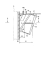
- FIG. 1 is a schematic view of a vertical mill according to an embodiment of the present invention.
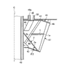
- FIG. 2 is a side sectional view of a rotary classifier according to an embodiment of the present invention.
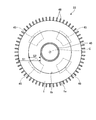
- FIG. 3 is a cross-sectional view taken along line AA in FIG.
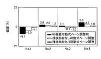
- FIG. 4 is a graph showing the flow rate deviation of pulverized coal discharged from the powder outlet at the time of classification.
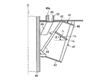
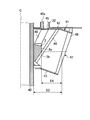
- FIG. 5 is a side sectional view of another example of a rotary classifier according to an embodiment of the present invention.
- FIG. 6 is a side sectional view of another example of a rotary classifier according to an embodiment of the present invention.
- FIG. 7 is a side cross-sectional view of another example of a rotary classifier according to an embodiment of the present invention.
- FIG. 1 is a schematic view of a vertical mill according to an embodiment of the present invention.
- the vertical mill according to the present embodiment is, for example, a combustion facility such as a boiler power generation, which grinds solid materials such as coal (raw coal) and biomass and supplies the pulverized coal which is crushed as fuel.
- biomass is an organic resource derived from renewable organisms. For example, thinned wood, waste wood, driftwood, grasses, waste, sludge, tires, and recycled fuels (pellets or chips) using these as raw materials Etc., and is not limited to the ones presented here.
- the housing 11 has a hollow cylindrical shape, and a coal supply pipe 12 is mounted on the top.
- the coal supply pipe 12 supplies coal to the inside of the housing 11 from a coal supply device (not shown), and is disposed along the vertical direction (vertical direction) at the center position of the cylinder of the housing 11.
- the lower end portion of the housing 11 extends downward to the inside of the housing 11.
- the grinding table 13 is disposed at the lower part of the housing 11.
- the grinding table 13 is disposed at the center position of the housing 11 so as to face the lower end portion of the coal supply pipe 12. Further, a rotation shaft (not shown) having a rotation axis along the vertical direction is connected to the lower part of the grinding table 13, and the rotation is driven via the rotation shaft.
- the crushing table 13 has a ring-shaped table liner 17 fixed to the outer peripheral side.
- the table liner 17 is an inclined surface which becomes higher as the surface (upper surface) goes to the outer edge side of the grinding table 13.
- a plurality of grinding rollers 18 are disposed above the grinding table 13 (table liner 17) so as to face the upper surface of the grinding table 13 (table liner 17).
- the grinding roller 18 is mounted on the support shaft 21.
- the rear end portion of the support shaft 21 is supported by the roller drive device 19.
- the roller driving device 19 is supported on the side wall portion of the housing 11 via the mounting shaft 22 so that the tip end portion of the support shaft 21 can swing in the vertical direction.
- the support shaft 21 is disposed such that the tip end thereof faces the rotation axis side of the grinding table 13 and is inclined downward, and the grinding roller 18 is attached to the tip end.
- a plurality of (for example, three) grinding rollers 18 are provided, and are disposed at equal intervals along the rotation direction of the grinding table 13.
- the number and arrangement of the grinding rollers 18 may be appropriately set in accordance with the size and the like of the grinding table 13 and the grinding rollers 18 and the like.
- the roller drive device 19 (support shaft 21) is provided with an upper arm 24 extending upward.
- the upper arm 24 is connected to the tip end of a pressing rod 26 of a hydraulic cylinder 25 as a pressing device fixed to the housing 11.
- the roller drive device 19 (support shaft 21) is provided with a lower arm 27 extending downward.
- the lower arm 27 can be in contact with a stopper 28 whose tip is fixed to the housing 11. Therefore, when the pressing rod 26 is advanced by the hydraulic cylinder 25, the upper arm 24 is pressed. Then, the roller driving device 19 and the support shaft 21 are rotationally moved clockwise in FIG. 1 with the mounting shaft 22 as a fulcrum. At this time, when the lower arm 27 abuts on the stopper 28, the rotational positions of the roller driving device 19 and the support shaft 21 are defined.
- the grinding roller 18 is for grinding coal with the grinding table 13 (table liner 17), and secures a predetermined gap between the surface of the grinding roller 18 and the surface of the grinding table 13 (table liner 17). There is a need. Therefore, by defining the support shaft 21 at a predetermined rotational position by the hydraulic cylinder 25, a predetermined gap capable of taking in and crushing coal is secured between the surface of the crushing roller 18 and the surface of the crushing table 13. Ru. Then, when the grinding table 13 rotates, the coal supplied onto the grinding table 13 is moved to the outer peripheral side by the centrifugal force and enters between the grinding roller 18 and the grinding table 13. Since the grinding roller 18 is pressed to the grinding table 13 side, the rotational force of the grinding table 13 is transmitted through the coal, and the grinding roller 18 can rotate in conjunction with the rotation of the grinding table 13 .
- the housing 11 is provided on the lower side thereof and around the outer edge of the grinding table 13 and an inlet port 31 is provided.
- the inlet port 31 feeds air into the housing 11.
- the housing 11 is provided with an outlet port 32 which is a pulverized coal pipe and located at the upper part thereof around the side of the coal supply pipe 12.
- the outlet port 32 discharges the coal pulverized as described above (pulverized coal) together with the air fed into the inside of the housing 11.
- the housing 11 is provided therein, below the outlet port 32, with a rotary separator 33 serving as a rotary classifier for classifying pulverized coal.
- the rotary separator 33 is rotatably provided on the outer periphery of the coal supply pipe 12 and is driven to rotate by the drive device 34.
- the housing 11 is provided with a foreign matter discharge pipe 35 at the lower part.
- the foreign matter discharge pipe 35 is for dropping foreign matter (spirage) such as soot and metal pieces mixed in coal from the outer peripheral portion of the rotating grinding table 13 and discharging the dropped foreign matter.
- FIG. 2 is a side cross-sectional view of the rotary classifier according to the present embodiment.
- FIG. 3 is a cross-sectional view taken along line AA in FIG.
- a right half part is shown and illustration of a left half part is abbreviate
- the rotary separator 33 has a cylindrical rotating shaft 40 as shown in FIGS. 2 and 3.
- the rotation shaft 40 extends along the vertical direction (vertical direction) so as to surround the coal supply pipe 12 and rotates around a rotation axis C which is the center of the cylindrical shape and extends in the vertical direction. It is supported possible.
- the rotation shaft 40 is driven to rotate by the drive device 34 described above.
- the rotary separator 33 also has a frame 41.
- the frame body 41 is formed of a circular upper support frame 42 and a lower support frame 43.
- the upper support frame 42 and the lower support frame 43 are supported by the rotation shaft 40 with the circular center disposed on the rotation axis C of the rotation shaft 40.
- the upper support frame 42 and the lower support frame 43 are mutually supported by a flat bar-like support member 44 disposed extending in the vertical direction between the upper support frame 42 and the lower support frame 43.
- a plurality (for example, six) of the support members 44 are equally arranged along the winding direction of the rotation axis C (the rotation direction of the rotation shaft 40).
- the frame body 41 is configured to close up and down by the upper support frame 42 and the lower support frame 43. Then, as shown in FIG.
- the upper support frame 42 is formed with an arc-shaped powder outlet 45 in which a plurality (for example, four locations) of the upper support frame 42 are equally arranged along the rotation direction about the rotation axis C. .
- the powder outlet 45 leads to an outlet port 32 which is a pulverized coal tube.
- movable vanes 49 are disposed on the lower side of the upper support frame 42 and corresponding to the rear sides of the powder outlets 45 in the rotational direction.
- the movable vane 49 is driven to rotate in a range of a predetermined angle through a shaft 49 a extending in the vertical direction by a drive device (not shown), whereby powder air flow inside the frame 41 is performed when the frame 41 rotates.
- the frame 41 has an opening 47 between the peripheries of the upper support frame 42 and the lower support frame 43 and in which a portion to be an outer peripheral portion is opened.
- a blade 48 is provided at an opening 47 between the upper support frame 42 and the lower support frame 43 with respect to the frame 41.
- the blades 48 extend in the vertical direction at the opening 47 of the outer peripheral portion of the frame 41, and a plurality (for example, 60) of the blades 48 are provided along the rotational direction.
- the blade 48 is formed in a flat plate shape, and is inclined with respect to the rotation axis C so that the upper end side is separated from the rotation shaft 40 and the lower end side approaches the rotation shaft 40.
- the blades 48 When the particles of pulverized coal intrude between the plurality of blades 48 in the rotational movement of the rotational axis C around which the rotational shaft 40 is rotationally driven, the blades 48 have a particle diameter smaller than the predetermined particle diameter.
- the fine powder is allowed to pass through, and coarse particles having a particle size larger than the predetermined particle size are classified by the blade 48 by preventing the passage between the external repelling blades 48.
- the rotational force of the pulverizing table 13 is transmitted to the pulverizing roller 18 through the coal, and the pulverizing roller 18 rotates as the pulverizing table 13 rotates.
- the crushing roller 18 since the crushing roller 18 is pressed and supported on the side of the crushing table 13 by the hydraulic cylinder 25, the crushing roller 18 presses and crushes the coal while rotating.
- the elevated pulverized coal is classified by the rotary separator 33, and the coarse particles are dropped and returned to the crushing table 13 again to be re-crushed.
- the fine powder passes through the rotary separator 33, is carried by the air flow, and is discharged from the outlet port 32.
- the spice such as soot and metal fragments mixed in the coal falls from the outer peripheral edge by the centrifugal force of the crushing table 13 and is discharged by the foreign matter discharge pipe 35.
- the coarse-grained powder in the pulverized coal has a large mass (weight), and thus has a large inertial force and high straightness. Therefore, the coarse-grained powder collides with the blades 48 and becomes difficult to pass between the blades 48, and is repelled to the outside of the frame 41 and eliminated.
- the fine powder in pulverized coal has a small mass (weight) as compared with the coarse powder, so the inertial force is small and the linearity is low.
- the fine powder hardly collides with the blades 48 and, even in the case of a collision, the fine powder passes between the blades 48 without being repelled to the outside of the frame 41 and enters the inside of the frame 41.
- the blades 48 can exclude coarse particles and can take only fine particles into the interior of the frame 41.
- the rotary separator 33 in the vertical mill according to the present embodiment is provided with the constriction portion in the above configuration.
- the constriction portion is provided to narrow the distance from the blade 48 to the rotation shaft 40, and extends from the blade 48 side to the rotation shaft 40 side to be continuous in the rotation direction It is comprised as an annular member 1 provided.
- the annular member 1 is a ring-shaped disc whose center is open and is disposed between the upper support frame 42 and the lower support frame 43, the outer edge 1a is supported by the blade 48, and the inner edge 1b is supported by the support member 44. It is supported and disposed inside the frame 41 rather than the blades 48. Accordingly, the annular member 1 as the narrowed portion has a distance S1 from the inner edge of the blade 48, which is the outer edge 1a, to the rotation shaft 40, and a distance S1 from the inner edge 1b to the rotation shaft 40 due to the width between the outer edge 1a and the inner edge 1b.
- the space between the upper support frame 42 and the lower support frame 43 inside the frame 41 is narrowed so as to narrow the space S 2.
- the fine powder in pulverized coal is taken into the inside of the frame 41 by the blades 48.
- the fine particles taken into the inside of the frame 41 rise inside the frame 41 while rotating along the circumference of the rotating shaft 40 by the swirling flow generated by the rotational movement of the blades 48.
- the fine powder rising inside the frame 41 eventually reaches each powder outlet 45, passes through the powder outlet 45, and is discharged from the outlet port 32.
- annular member 1 as a throttling portion is provided. For this reason, when the upward flow which ascends the inside of the frame 41 by the swirling flow passes in such a way as to be pushed inward between the inner edge 1b narrowed by the annular member 1 and the rotating shaft 40, angular momentum conservation The swirling flow rate is increased. The flow velocity deviation in the circumferential direction is reduced by increasing the swirl flow velocity. As a result, the powdery gas including the fine particles taken into the inside of the frame 41 by the blades 48 is uniformly sent to the powder outlets 45 by the increased swirling flow.
- FIG. 4 is a graph showing the flow rate deviation of pulverized coal discharged from the powder outlet at the time of classification.
- FIG. 1 to No. 4 correspond to four powder outlets arranged in the rotational direction of the rotary separator.
- the black part corresponds to 9% deviation before adjustment by the movable vane 49
- the white part is a rotary separator which does not have the annular member 1 as the above-described throttling part and is movable
- the hatched portion corresponds to the rotary separator provided with the annular member 1 as the narrowed portion described above and corresponds to the adjustment after the movable vane 49.
- the deviation could be reduced (adjusted) to 1.1%.
- the rotary separator (rotational classifier) 33 of the present embodiment is supported by the rotation shaft 40 rotatably supported around the rotation axis C extending in the vertical direction and the rotation shaft 40.
- the plurality of powder outlets 45 provided open in the upper part of the frame 41, and the opening 47 in the outer peripheral portion of the frame 41
- a plurality of blades 48 are provided extending along the rotational direction, and an annular member 1 as a narrowed portion provided to narrow the distance from the blades 48 to the rotation shaft 40.
- the angular momentum when the upflow which ascends the inside of the frame 41 by the swirling flow by the rotationally moving blades 48 passes the portion narrowed by the annular member 1 so as to be moved inward.
- the storage increases the swirl flow velocity.
- the flow velocity deviation in the circumferential direction is reduced by increasing the swirl flow velocity.
- the movable vanes 49 are disposed corresponding to the rear side of each powder outlet 45, and the damming effect by the movable vanes 49 improves the even distribution of the powder gas.
- the damming effect of the particles in the movable vane 49 is improved by the annular member 1, and the even distribution of the pulverized coal amount can be further improved.
- FIGS. 5 to 7 are side sectional views of another example of the rotary classifier according to the present embodiment.
- the right half part is shown and the left half part is omitted because it is constructed symmetrically with reference to the rotation axis C.
- the annular member 1 as the narrowed portion described above is directed upward from the blade 48 side to the rotary shaft 40 side at the bottom thereof. It has the inclined surface 1c formed.
- the plate-like annular member 1 is inclined upward from the blade 48 side to the rotary shaft 40 side to form an inclined surface 1c.
- the inclined surface 1 c is provided in a flat shape in cross section in the entire area from the blade 48 side of the annular member 1 to the rotary shaft 40 side.
- the inclined surface 1c is not provided in the entire area from the blade 48 side of the annular member 1 to the rotary shaft 40 side, for example, the blade 48 side or the rotary shaft 40 side is partially inclined. It may be Further, although not clearly shown in the figure, the inclined surface 1c is not limited to a flat surface, and is formed in a curved curved shape in which a tangent line gradually extends upward and approaches vertical from the blade 48 side to the rotary shaft 40 side. It may be Moreover, although not clearly shown in the drawing, only the bottom of the annular member 1 may be formed to be inclined.
- the inclined surface 1c of the annular member 1 rectifies the upward flow rising inside the frame body 41 by the swirling flow by the blades 48 that are rotationally moved. For this reason, the drift that the flow velocity distribution of the powder gas is biased in the inner region of the frame 41 is further reduced. As a result, the effect of improving the even distribution of the powder gas delivered to the outside of the frame 41 at each powder outlet 45 can be significantly obtained.
- the angle ⁇ 1 with respect to the horizontal of the inclined surface 1c in the range of -50 deg or more and 50 deg or less.
- the rotary shaft 40 is provided from the outer peripheral side of the inner bottom of the frame 41 in the configuration provided with the annular member 1 as the throttling portion described above.
- the bottom member 2 is provided with an inclined surface 2a which is provided upward toward the side and is continuous in the rotational direction.
- the inclined surface 2a extends from the lower end side of the blade 48 to the rotating shaft 40, and is provided so as to have a flat cross section over the entire area.
- the inclined surface 2a is not provided in the entire area from the lower end side of the blade 48 to the rotating shaft 40, and for example, the lower end side of the blade 48 or the rotating shaft 40 side is partially inclined. It may be Further, although not clearly shown in the figure, the inclined surface 2a is not limited to a flat surface, and is formed into a curved curved shape in which a tangent line gradually extends upward and approaches vertical from the lower end side of the blade 48 to the rotating shaft 40. It may be done.
- the inclined surface 2a of the bottom member 2 rectifies the upward flow rising inside the frame body 41 by the swirling flow of the blades 48 that are rotationally moved. For this reason, the drift that the flow velocity distribution of the powder gas is biased in the inner region of the frame 41 is further reduced. As a result, in synergy with the effect of the annular member 1, the effect of improving the even distribution of the powder gas delivered to the outside of the frame 41 at each powder outlet 45 can be more significantly obtained.
- the angle ⁇ 2 with respect to the horizontal surface of the inclined surface 2a in the range of 20 degrees to 60 degrees.
- the narrowing portion reduces the distance from the rotation shaft 40 side so as to narrow the distance from the blade 48 to the rotation shaft 40 side. It consists of the convex member 3 which protruded to the 48 side and was provided continuously in the rotation direction.
- the convex member 3 is supported by the rotary shaft 40 and disposed between the upper support frame 42 and the lower support frame 43, and the projection from the rotary shaft 40 is terminated at a position inside the frame 41 than the blades 48 There is. Therefore, the convex member 3 as the narrowed portion narrows the distance S3 from the inner edge of the blade 48 to the rotation shaft 40 to the distance S4 from the inner edge of the blade 48 to the end 3a depending on the position of the end 3a. It is provided to narrow the space between the upper upper support frame 42 and the lower support frame 43 inside.
- the interval S4 is a distance from the inner edge of the blade 48 at a horizontal position based on the position where the convex member 3 protrudes most to the blade 48 side. Then, as shown in FIG. 7, when the position where the convex member 3 protrudes most to the blade 48 side is parallel to the rotation axis C, the horizontal position based on the lowermost position is from the inner edge of the blade 48 And the distance.
- this rotary separator 33 when the upward flow which ascends the inside of the frame 41 by the swirling flow by the rotationally moving blades 48 passes the portion narrowed by the convex member 3, the angular momentum is increased and the swirling flow velocity is increased. Be done. The flow velocity deviation in the circumferential direction is reduced by increasing the swirl flow velocity. As a result, it is possible to improve the even distribution of the powder gas delivered to the outside of the frame 41 at each powder outlet 45.
- the movable vanes 49 are disposed corresponding to the rear side of each powder outlet 45, and the damming effect by the movable vanes 49 improves the even distribution of the powder gas.
- the effect of blocking particles in the movable vane 49 is improved by the convex member 3, and the even distribution of the amount of pulverized coal can be further improved.
- the convex member 3 has an inclined surface 3 b formed on the lower side thereof from the side of the rotation shaft 40 to the side of the blade 48 upward.
- the inclined surface 3 b extends from the lower end side to the end 3 a of the rotary shaft 40 inside the frame 41, and is provided in a flat shape in cross section in the entire area.
- the inclined surface 3 b may not be provided in the entire area from the lower end side of the rotation shaft 40 to the end 3 a inside the frame 41, and may be partially inclined.
- the inclined surface 3b is not limited to being flat, but it extends from the lower end side of the rotary shaft 40 to the end 3a inside the frame 41 and gradually makes the tangent line upward and approach vertical. It may be formed in a curved cross-sectional shape.
- the inclined surface 3b of the convex member 3 rectifies the upward flow rising inside the frame body 41 by the swirling flow by the blades 48 that are rotationally moved. For this reason, the drift that the flow velocity distribution of the powder gas is biased in the inner region of the frame 41 is further reduced. As a result, the effect of improving the even distribution of the powder gas delivered to the outside of the frame 41 at each powder outlet 45 can be significantly obtained.
- the rotary separator 33 as the rotary classifier according to the present embodiment described above has powder gas in the inner region of the frame 41 in the configuration in which the movable vanes 49 are provided corresponding to the respective powder outlets 45.
- the effect of improving the even distribution of the powder gas delivered to the outside of the frame 41 at each powder outlet 45 can be more significantly obtained by reducing the uneven flow of the flow velocity distribution.
- the vertical mill includes a hollow housing 11, a crushing table 13 provided at a lower portion in the housing 11 and rotated about a rotation axis along the vertical direction, and an upper surface of the crushing table 13 And a rotary roller (rotary classifier) 33 provided at the upper part in the housing 11 and disposed opposite to and rotatably supported.
- this vertical mill it is possible to improve the even distribution of the powder gas delivered to the outside of the frame at each powder outlet 45 by the rotary separator 33 having the throttling portion. For this reason, when solid materials such as coal (raw coal) and biomass are pulverized, pulverized pulverized coal can be uniformly supplied to the combustion equipment. Moreover, according to this vertical mill, the amount of pulverized coal at the outlet of each powder can be optionally deviated by the narrowing section.
Landscapes
- Engineering & Computer Science (AREA)
- Food Science & Technology (AREA)
- Crushing And Grinding (AREA)
- Combined Means For Separation Of Solids (AREA)
- Disintegrating Or Milling (AREA)
Priority Applications (3)
| Application Number | Priority Date | Filing Date | Title |
|---|---|---|---|
| DE112015005613.0T DE112015005613B4 (de) | 2014-12-16 | 2015-08-19 | Rotationsklassierer und Vertikalmühle |
| CN201580067924.6A CN106999946B (zh) | 2014-12-16 | 2015-08-19 | 旋转式分级机以及立式粉碎机 |
| US15/622,314 US10882050B2 (en) | 2014-12-16 | 2017-06-14 | Rotary classifier and vertical mill |
Applications Claiming Priority (2)
| Application Number | Priority Date | Filing Date | Title |
|---|---|---|---|
| JP2014254188A JP6415298B2 (ja) | 2014-12-16 | 2014-12-16 | 回転式分級機および竪型ミル |
| JP2014-254188 | 2014-12-16 |
Related Child Applications (1)
| Application Number | Title | Priority Date | Filing Date |
|---|---|---|---|
| US15/622,314 Continuation US10882050B2 (en) | 2014-12-16 | 2017-06-14 | Rotary classifier and vertical mill |
Publications (1)
| Publication Number | Publication Date |
|---|---|
| WO2016098386A1 true WO2016098386A1 (ja) | 2016-06-23 |
Family
ID=56126290
Family Applications (1)
| Application Number | Title | Priority Date | Filing Date |
|---|---|---|---|
| PCT/JP2015/073257 Ceased WO2016098386A1 (ja) | 2014-12-16 | 2015-08-19 | 回転式分級機および竪型ミル |
Country Status (5)
| Country | Link |
|---|---|
| US (1) | US10882050B2 (https=) |
| JP (1) | JP6415298B2 (https=) |
| CN (1) | CN106999946B (https=) |
| DE (1) | DE112015005613B4 (https=) |
| WO (1) | WO2016098386A1 (https=) |
Families Citing this family (2)
| Publication number | Priority date | Publication date | Assignee | Title |
|---|---|---|---|---|
| DE102016121925A1 (de) * | 2016-11-15 | 2018-05-17 | Neuman & Esser Gmbh Mahl- Und Sichtsysteme | Sichter, Mühle und Verfahren zum Sichten eines Gas-Feststoff-Gemischs |
| JP7439578B2 (ja) * | 2020-03-10 | 2024-02-28 | 株式会社Ihi | 竪型ローラミル |
Citations (4)
| Publication number | Priority date | Publication date | Assignee | Title |
|---|---|---|---|---|
| JPH02251279A (ja) * | 1989-03-23 | 1990-10-09 | Onoda Eng Kk | 空気分級機 |
| JPH0518971U (ja) * | 1991-08-23 | 1993-03-09 | 本田技研工業株式会社 | アームレスト付シート |
| JPH07236861A (ja) * | 1994-02-28 | 1995-09-12 | Mitsubishi Heavy Ind Ltd | 回転式分級装置 |
| WO2007097042A1 (ja) * | 2006-02-24 | 2007-08-30 | Taiheiyo Cement Corporation | 遠心式空気分級機 |
Family Cites Families (18)
| Publication number | Priority date | Publication date | Assignee | Title |
|---|---|---|---|---|
| CN85106642B (zh) * | 1985-09-03 | 1988-12-14 | 川崎重工业株式会社 | 立式辊碾机分级器及控制器 |
| JP2617832B2 (ja) * | 1991-05-17 | 1997-06-04 | 宇部興産株式会社 | 竪型粉砕機 |
| JPH0677863A (ja) | 1991-07-04 | 1994-03-18 | Reideitsuku:Kk | 地中データ収集装置 |
| JPH0677863U (ja) * | 1993-04-14 | 1994-11-01 | 石川島播磨重工業株式会社 | 回転式分級機 |
| US5927510A (en) * | 1997-02-19 | 1999-07-27 | Xerox Corporation | Particle classification apparatus and processes thereof |
| US5944270A (en) * | 1998-06-26 | 1999-08-31 | Combustion Engineering, Inc. | Self-contained air seal assembly for coal pulverizer |
| US6607079B2 (en) | 2001-08-16 | 2003-08-19 | Foster Wheeler Energy Corporation | System and method for controlling particle flow distribution between the outlets of a classifier |
| US6902126B2 (en) * | 2002-11-04 | 2005-06-07 | Alstom Technology Ltd | Hybrid turbine classifier |
| NO321643B1 (no) * | 2004-05-18 | 2006-06-19 | Comex As | Partikkelseparator |
| ES2393646B2 (es) | 2008-01-24 | 2014-09-10 | Mitsubishi Heavy Industries, Ltd. | Estructura de molino triturador. |
| JP5716272B2 (ja) * | 2009-11-09 | 2015-05-13 | 株式会社Ihi | 竪型ローラミル |
| JP2011104563A (ja) * | 2009-11-20 | 2011-06-02 | Mitsubishi Heavy Ind Ltd | 竪型ローラミル |
| JP5645468B2 (ja) * | 2010-05-14 | 2014-12-24 | 三菱重工業株式会社 | バイオマス粉砕装置及びバイオマス・石炭混焼システム |
| FR2976194B1 (fr) * | 2011-06-08 | 2014-01-10 | Pa Technologies | Separateur dynamique pour materiaux pulverulents |
| CN102389852B (zh) * | 2011-11-22 | 2013-10-02 | 江苏羚羊水泥工程技术有限公司 | 多次分选式高效水泥立磨 |
| US8820535B2 (en) * | 2012-02-07 | 2014-09-02 | Rickey E. Wark | Classifier with variable entry ports |
| CN102716855B (zh) * | 2012-06-29 | 2015-01-28 | 冯桂宏 | 立式磨机低速大转矩永磁电动机直驱式选粉机及选粉方法 |
| WO2015033312A2 (en) * | 2013-09-09 | 2015-03-12 | Coal Milling Projects (Pty) Limited | An ultra high performance static classifier |
-
2014
- 2014-12-16 JP JP2014254188A patent/JP6415298B2/ja active Active
-
2015
- 2015-08-19 WO PCT/JP2015/073257 patent/WO2016098386A1/ja not_active Ceased
- 2015-08-19 DE DE112015005613.0T patent/DE112015005613B4/de active Active
- 2015-08-19 CN CN201580067924.6A patent/CN106999946B/zh active Active
-
2017
- 2017-06-14 US US15/622,314 patent/US10882050B2/en active Active
Patent Citations (4)
| Publication number | Priority date | Publication date | Assignee | Title |
|---|---|---|---|---|
| JPH02251279A (ja) * | 1989-03-23 | 1990-10-09 | Onoda Eng Kk | 空気分級機 |
| JPH0518971U (ja) * | 1991-08-23 | 1993-03-09 | 本田技研工業株式会社 | アームレスト付シート |
| JPH07236861A (ja) * | 1994-02-28 | 1995-09-12 | Mitsubishi Heavy Ind Ltd | 回転式分級装置 |
| WO2007097042A1 (ja) * | 2006-02-24 | 2007-08-30 | Taiheiyo Cement Corporation | 遠心式空気分級機 |
Also Published As
| Publication number | Publication date |
|---|---|
| CN106999946A (zh) | 2017-08-01 |
| US20170274386A1 (en) | 2017-09-28 |
| DE112015005613T5 (de) | 2017-09-14 |
| DE112015005613B4 (de) | 2026-01-08 |
| JP2016112519A (ja) | 2016-06-23 |
| US10882050B2 (en) | 2021-01-05 |
| CN106999946B (zh) | 2019-05-03 |
| JP6415298B2 (ja) | 2018-10-31 |
Similar Documents
| Publication | Publication Date | Title |
|---|---|---|
| JP5730761B2 (ja) | 円錐形状衝撃式ミル | |
| US9211547B2 (en) | Classifier | |
| JP5905366B2 (ja) | 回転式分級機及び竪型ミル | |
| CN109475878A (zh) | 立式辊磨机 | |
| EP2745939B1 (en) | Grinding mill | |
| US8567705B2 (en) | Vertical mill | |
| CN203695426U (zh) | 超细粉体气流分级机 | |
| WO2016098386A1 (ja) | 回転式分級機および竪型ミル | |
| JP6896399B2 (ja) | 固体燃料粉砕装置及びその運転方法 | |
| JP6549062B2 (ja) | 縦型ミル | |
| KR102091099B1 (ko) | 세퍼레이터 일체형 인라인 충격식 기류분급 분쇄장치 | |
| KR101513054B1 (ko) | 2단 수직 원심 분급기 | |
| JP2016150300A (ja) | 竪型粉砕機 | |
| WO2019059063A1 (ja) | バイオマスミル | |
| JP2012115738A (ja) | バイオマスミル | |
| JP2012217920A (ja) | 竪型ミル | |
| JP6856311B2 (ja) | 竪型粉砕機 | |
| JP5810542B2 (ja) | バイオマスミル | |
| JP5577668B2 (ja) | 竪型ローラミル | |
| KR100660140B1 (ko) | 곡물 분쇄장치 | |
| JP2012115819A (ja) | 粉砕機 | |
| JP2570708Y2 (ja) | 竪型粉砕機 | |
| JPH0319969Y2 (https=) | ||
| JP2018001056A (ja) | 竪型粉砕機 | |
| JP2018001055A (ja) | 竪型粉砕機 |
Legal Events
| Date | Code | Title | Description |
|---|---|---|---|
| 121 | Ep: the epo has been informed by wipo that ep was designated in this application |
Ref document number: 15869595 Country of ref document: EP Kind code of ref document: A1 |
|
| WWE | Wipo information: entry into national phase |
Ref document number: 112015005613 Country of ref document: DE |
|
| 122 | Ep: pct application non-entry in european phase |
Ref document number: 15869595 Country of ref document: EP Kind code of ref document: A1 |
|
| WWG | Wipo information: grant in national office |
Ref document number: 112015005613 Country of ref document: DE |