WO2016098386A1 - 回転式分級機および竪型ミル - Google Patents
回転式分級機および竪型ミル Download PDFInfo
- Publication number
- WO2016098386A1 WO2016098386A1 PCT/JP2015/073257 JP2015073257W WO2016098386A1 WO 2016098386 A1 WO2016098386 A1 WO 2016098386A1 JP 2015073257 W JP2015073257 W JP 2015073257W WO 2016098386 A1 WO2016098386 A1 WO 2016098386A1
- Authority
- WO
- WIPO (PCT)
- Prior art keywords
- rotary
- frame
- blade
- shaft
- powder
- Prior art date
Links
Images

Classifications
-
- B—PERFORMING OPERATIONS; TRANSPORTING
- B02—CRUSHING, PULVERISING, OR DISINTEGRATING; PREPARATORY TREATMENT OF GRAIN FOR MILLING
- B02C—CRUSHING, PULVERISING, OR DISINTEGRATING IN GENERAL; MILLING GRAIN
- B02C15/00—Disintegrating by milling members in the form of rollers or balls co-operating with rings or discs
- B02C15/007—Mills with rollers pressed against a rotary horizontal disc
-
- B—PERFORMING OPERATIONS; TRANSPORTING
- B07—SEPARATING SOLIDS FROM SOLIDS; SORTING
- B07B—SEPARATING SOLIDS FROM SOLIDS BY SIEVING, SCREENING, SIFTING OR BY USING GAS CURRENTS; SEPARATING BY OTHER DRY METHODS APPLICABLE TO BULK MATERIAL, e.g. LOOSE ARTICLES FIT TO BE HANDLED LIKE BULK MATERIAL
- B07B7/00—Selective separation of solid materials carried by, or dispersed in, gas currents
- B07B7/08—Selective separation of solid materials carried by, or dispersed in, gas currents using centrifugal force
- B07B7/083—Selective separation of solid materials carried by, or dispersed in, gas currents using centrifugal force generated by rotating vanes, discs, drums, or brushes
-
- B—PERFORMING OPERATIONS; TRANSPORTING
- B02—CRUSHING, PULVERISING, OR DISINTEGRATING; PREPARATORY TREATMENT OF GRAIN FOR MILLING
- B02C—CRUSHING, PULVERISING, OR DISINTEGRATING IN GENERAL; MILLING GRAIN
- B02C15/00—Disintegrating by milling members in the form of rollers or balls co-operating with rings or discs
- B02C15/04—Mills with pressed pendularly-mounted rollers, e.g. spring pressed
-
- B—PERFORMING OPERATIONS; TRANSPORTING
- B02—CRUSHING, PULVERISING, OR DISINTEGRATING; PREPARATORY TREATMENT OF GRAIN FOR MILLING
- B02C—CRUSHING, PULVERISING, OR DISINTEGRATING IN GENERAL; MILLING GRAIN
- B02C23/00—Auxiliary methods or auxiliary devices or accessories specially adapted for crushing or disintegrating not provided for in preceding groups or not specially adapted to apparatus covered by a single preceding group
- B02C23/08—Separating or sorting of material, associated with crushing or disintegrating
- B02C23/10—Separating or sorting of material, associated with crushing or disintegrating with separator arranged in discharge path of crushing or disintegrating zone
- B02C23/12—Separating or sorting of material, associated with crushing or disintegrating with separator arranged in discharge path of crushing or disintegrating zone with return of oversize material to crushing or disintegrating zone
-
- B—PERFORMING OPERATIONS; TRANSPORTING
- B01—PHYSICAL OR CHEMICAL PROCESSES OR APPARATUS IN GENERAL
- B01D—SEPARATION
- B01D45/00—Separating dispersed particles from gases or vapours by gravity, inertia, or centrifugal forces
- B01D45/12—Separating dispersed particles from gases or vapours by gravity, inertia, or centrifugal forces by centrifugal forces
- B01D45/14—Separating dispersed particles from gases or vapours by gravity, inertia, or centrifugal forces by centrifugal forces generated by rotating vanes, discs, drums or brushes
-
- B—PERFORMING OPERATIONS; TRANSPORTING
- B02—CRUSHING, PULVERISING, OR DISINTEGRATING; PREPARATORY TREATMENT OF GRAIN FOR MILLING
- B02C—CRUSHING, PULVERISING, OR DISINTEGRATING IN GENERAL; MILLING GRAIN
- B02C15/00—Disintegrating by milling members in the form of rollers or balls co-operating with rings or discs
- B02C2015/002—Disintegrating by milling members in the form of rollers or balls co-operating with rings or discs combined with a classifier
Definitions
- the present invention relates to a rotary classifier that classifies solid materials such as coal and biomass into fine particles after pulverization, and a vertical mill to which the rotary classifier is applied.
- solid fuel such as coal and biomass is used as fuel. And when using this coal etc. as solid fuel, it is made to grind
- a grinding table is disposed rotatably at a lower portion of a housing, and a plurality of grinding rollers can be rotated together with a grinding load on an upper surface of the grinding table.
- a rotary classifier is disposed at the top of the housing. Therefore, when the raw coal is supplied from the coal feed pipe onto the grinding table, it is dispersed over the entire surface by the centrifugal force to form a coal bed, and the grinding rollers press the coal bed to grind it. Then, the pulverized coal which has been crushed is dried by the supplied air, and then classified to a predetermined particle diameter or less by a rotary classifier, and only the pulverized coal having the appropriate particle diameter is discharged to the outside.
- the vertical crusher described in Patent Document 2 aims to obtain a product of particle size distribution having sharp classification characteristics with little variation in particle size distribution of products after classification.
- This vertical crusher comprises a rotary separator comprising a vertical drive shaft rotatably supported at the center of the classification chamber and a large number of flat classification blades integrally rotating around the vertical drive shaft, the classification chamber
- the classification blade enlarges the inclination angle as it goes upward from the lower side in side view
- the outer diameter side is formed to be retracted relative to the rotation direction in plan view of the classification blade compared to the inner diameter side, and the retraction angle of the classification blade is different between the upper half and the lower half.
- the flow straightening means is a movable vane that operates to adjust the flow passage cross-sectional area, and the opening degree of the movable vane is changed to adjust the blocking amount of the swirling particles.
- the aim is to improve the even distribution of powder fluid to a plurality of pulverized coal pipes.
- the movable vane alone has a limitation in the blocking effect, and the even distribution is insufficient. Since the movable vanes are provided on the upper side of the inside of the classifier having a relatively large space, the flow rate of the powder fluid is generated on the lower side of the inside of the classifier, which is a relatively narrow space. , It is difficult to obtain the effect of equal distribution sufficiently.
- the present invention solves the above-mentioned problems, and an object of the present invention is to provide a rotary classifier and a vertical mill capable of improving the even distribution of powder fluid.
- a rotary classifier comprises: a rotary shaft rotatably supported about a rotary shaft extending in the vertical direction; Extending in the vertical direction at a frame having an opening at the outer periphery, a plurality of powder outlets opened at the top of the frame and provided along the rotational direction, and the opening at the outer periphery of the frame A plurality of blades provided along the rotational direction, and a constricted portion provided to narrow a distance from the blades to the rotation axis are provided.
- the narrowed portion narrows the distance between the blade and the rotary shaft from the blade to the rotary shaft from the blade side. It is characterized in that it comprises an annular member extending to the side and continuously provided in the rotational direction.
- the annular member has an inclined surface which is formed at the bottom portion upward from the blade side to the rotary shaft side.
- the inclined surface of the annular member rectifies the upward flow rising inside the frame by the swirling flow by the blades moving in rotation. For this reason, the drift that the flow velocity distribution of the powder gas is biased in the inner region of the frame is further reduced. As a result, the effect of improving the even distribution of the powder gas delivered to the outside of the frame at each powder outlet can be significantly obtained.
- the rotary classifier according to a fourth aspect of the present invention is characterized in that in the third aspect, the annular member has an angle of -50 deg or more and 50 deg or less with respect to the horizontal surface of the inclined surface.
- this rotary classifier by setting the angle with respect to the horizontal of the inclined surface in the range of -50 deg or more and 50 deg or less, it is possible to suitably obtain the action of rectifying the upward flow.
- the rotary classifier according to the fifth invention is, in any one of the second to fourth inventions, provided upward from the outer peripheral side of the inner bottom of the frame toward the rotary shaft side, A bottom member having an inclined surface continuous in the rotational direction is provided.
- the inclined surface at the bottom portion rectifies the upward flow rising inside the frame by the swirling flow by the blades moving in rotation. For this reason, the drift that the flow velocity distribution of the powder gas is biased in the inner region of the frame is further reduced. As a result, in synergy with the effect of the annular member, the effect of improving the even distribution of the powder gas delivered to the outside of the frame at each powder outlet can be more significantly obtained.
- the rotary classifier according to a sixth aspect of the present invention is characterized in that in the fifth aspect, the bottom member has an angle of 20 degrees or more and 60 degrees or less with respect to the horizontal surface of the inclined surface.
- this rotary classifier by setting the angle with respect to the horizontal of the inclined surface in the range of 20 deg or more and 60 deg or less, it is possible to suitably obtain the action of rectifying the upward flow.
- the narrowed portion narrows the gap on the blade side from the blade to the rotating shaft, and the blade side from the rotating shaft side And a convex member provided continuously in the rotational direction.
- the vertical mill according to the eighth aspect of the present invention comprises a hollow housing, a grinding table provided at a lower portion in the housing and rotated about a rotation axis along the vertical direction, and an upper surface of the grinding table It is characterized in that it comprises a grinding roller disposed so as to face the peripheral surface and rotatably supported, and any one of the above-mentioned rotary classifiers provided at the upper part in the housing.
- this vertical mill it is possible to improve the even distribution of the powder gas delivered to the outside of the frame at each powder outlet by the rotary classifier provided with the throttling portion. For this reason, when solid materials such as coal (raw coal) and biomass are pulverized, pulverized pulverized coal can be uniformly supplied to the combustion equipment. Moreover, according to this vertical mill, the amount of pulverized coal at the outlet of each powder can be optionally deviated by the narrowing section.
- FIG. 1 is a schematic view of a vertical mill according to an embodiment of the present invention.
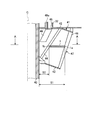
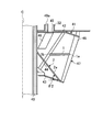
- FIG. 2 is a side sectional view of a rotary classifier according to an embodiment of the present invention.
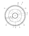
- FIG. 3 is a cross-sectional view taken along line AA in FIG.
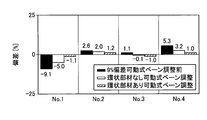
- FIG. 4 is a graph showing the flow rate deviation of pulverized coal discharged from the powder outlet at the time of classification.
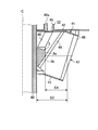
- FIG. 5 is a side sectional view of another example of a rotary classifier according to an embodiment of the present invention.
- FIG. 6 is a side sectional view of another example of a rotary classifier according to an embodiment of the present invention.
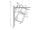
- FIG. 7 is a side cross-sectional view of another example of a rotary classifier according to an embodiment of the present invention.
- FIG. 1 is a schematic view of a vertical mill according to an embodiment of the present invention.
- the vertical mill according to the present embodiment is, for example, a combustion facility such as a boiler power generation, which grinds solid materials such as coal (raw coal) and biomass and supplies the pulverized coal which is crushed as fuel.
- biomass is an organic resource derived from renewable organisms. For example, thinned wood, waste wood, driftwood, grasses, waste, sludge, tires, and recycled fuels (pellets or chips) using these as raw materials Etc., and is not limited to the ones presented here.
- the housing 11 has a hollow cylindrical shape, and a coal supply pipe 12 is mounted on the top.
- the coal supply pipe 12 supplies coal to the inside of the housing 11 from a coal supply device (not shown), and is disposed along the vertical direction (vertical direction) at the center position of the cylinder of the housing 11.
- the lower end portion of the housing 11 extends downward to the inside of the housing 11.
- the grinding table 13 is disposed at the lower part of the housing 11.
- the grinding table 13 is disposed at the center position of the housing 11 so as to face the lower end portion of the coal supply pipe 12. Further, a rotation shaft (not shown) having a rotation axis along the vertical direction is connected to the lower part of the grinding table 13, and the rotation is driven via the rotation shaft.
- the crushing table 13 has a ring-shaped table liner 17 fixed to the outer peripheral side.
- the table liner 17 is an inclined surface which becomes higher as the surface (upper surface) goes to the outer edge side of the grinding table 13.
- a plurality of grinding rollers 18 are disposed above the grinding table 13 (table liner 17) so as to face the upper surface of the grinding table 13 (table liner 17).
- the grinding roller 18 is mounted on the support shaft 21.
- the rear end portion of the support shaft 21 is supported by the roller drive device 19.
- the roller driving device 19 is supported on the side wall portion of the housing 11 via the mounting shaft 22 so that the tip end portion of the support shaft 21 can swing in the vertical direction.
- the support shaft 21 is disposed such that the tip end thereof faces the rotation axis side of the grinding table 13 and is inclined downward, and the grinding roller 18 is attached to the tip end.
- a plurality of (for example, three) grinding rollers 18 are provided, and are disposed at equal intervals along the rotation direction of the grinding table 13.
- the number and arrangement of the grinding rollers 18 may be appropriately set in accordance with the size and the like of the grinding table 13 and the grinding rollers 18 and the like.
- the roller drive device 19 (support shaft 21) is provided with an upper arm 24 extending upward.
- the upper arm 24 is connected to the tip end of a pressing rod 26 of a hydraulic cylinder 25 as a pressing device fixed to the housing 11.
- the roller drive device 19 (support shaft 21) is provided with a lower arm 27 extending downward.
- the lower arm 27 can be in contact with a stopper 28 whose tip is fixed to the housing 11. Therefore, when the pressing rod 26 is advanced by the hydraulic cylinder 25, the upper arm 24 is pressed. Then, the roller driving device 19 and the support shaft 21 are rotationally moved clockwise in FIG. 1 with the mounting shaft 22 as a fulcrum. At this time, when the lower arm 27 abuts on the stopper 28, the rotational positions of the roller driving device 19 and the support shaft 21 are defined.
- the grinding roller 18 is for grinding coal with the grinding table 13 (table liner 17), and secures a predetermined gap between the surface of the grinding roller 18 and the surface of the grinding table 13 (table liner 17). There is a need. Therefore, by defining the support shaft 21 at a predetermined rotational position by the hydraulic cylinder 25, a predetermined gap capable of taking in and crushing coal is secured between the surface of the crushing roller 18 and the surface of the crushing table 13. Ru. Then, when the grinding table 13 rotates, the coal supplied onto the grinding table 13 is moved to the outer peripheral side by the centrifugal force and enters between the grinding roller 18 and the grinding table 13. Since the grinding roller 18 is pressed to the grinding table 13 side, the rotational force of the grinding table 13 is transmitted through the coal, and the grinding roller 18 can rotate in conjunction with the rotation of the grinding table 13 .
- the housing 11 is provided on the lower side thereof and around the outer edge of the grinding table 13 and an inlet port 31 is provided.
- the inlet port 31 feeds air into the housing 11.
- the housing 11 is provided with an outlet port 32 which is a pulverized coal pipe and located at the upper part thereof around the side of the coal supply pipe 12.
- the outlet port 32 discharges the coal pulverized as described above (pulverized coal) together with the air fed into the inside of the housing 11.
- the housing 11 is provided therein, below the outlet port 32, with a rotary separator 33 serving as a rotary classifier for classifying pulverized coal.
- the rotary separator 33 is rotatably provided on the outer periphery of the coal supply pipe 12 and is driven to rotate by the drive device 34.
- the housing 11 is provided with a foreign matter discharge pipe 35 at the lower part.
- the foreign matter discharge pipe 35 is for dropping foreign matter (spirage) such as soot and metal pieces mixed in coal from the outer peripheral portion of the rotating grinding table 13 and discharging the dropped foreign matter.
- FIG. 2 is a side cross-sectional view of the rotary classifier according to the present embodiment.
- FIG. 3 is a cross-sectional view taken along line AA in FIG.
- a right half part is shown and illustration of a left half part is abbreviate
- the rotary separator 33 has a cylindrical rotating shaft 40 as shown in FIGS. 2 and 3.
- the rotation shaft 40 extends along the vertical direction (vertical direction) so as to surround the coal supply pipe 12 and rotates around a rotation axis C which is the center of the cylindrical shape and extends in the vertical direction. It is supported possible.
- the rotation shaft 40 is driven to rotate by the drive device 34 described above.
- the rotary separator 33 also has a frame 41.
- the frame body 41 is formed of a circular upper support frame 42 and a lower support frame 43.
- the upper support frame 42 and the lower support frame 43 are supported by the rotation shaft 40 with the circular center disposed on the rotation axis C of the rotation shaft 40.
- the upper support frame 42 and the lower support frame 43 are mutually supported by a flat bar-like support member 44 disposed extending in the vertical direction between the upper support frame 42 and the lower support frame 43.
- a plurality (for example, six) of the support members 44 are equally arranged along the winding direction of the rotation axis C (the rotation direction of the rotation shaft 40).
- the frame body 41 is configured to close up and down by the upper support frame 42 and the lower support frame 43. Then, as shown in FIG.
- the upper support frame 42 is formed with an arc-shaped powder outlet 45 in which a plurality (for example, four locations) of the upper support frame 42 are equally arranged along the rotation direction about the rotation axis C. .
- the powder outlet 45 leads to an outlet port 32 which is a pulverized coal tube.
- movable vanes 49 are disposed on the lower side of the upper support frame 42 and corresponding to the rear sides of the powder outlets 45 in the rotational direction.
- the movable vane 49 is driven to rotate in a range of a predetermined angle through a shaft 49 a extending in the vertical direction by a drive device (not shown), whereby powder air flow inside the frame 41 is performed when the frame 41 rotates.
- the frame 41 has an opening 47 between the peripheries of the upper support frame 42 and the lower support frame 43 and in which a portion to be an outer peripheral portion is opened.
- a blade 48 is provided at an opening 47 between the upper support frame 42 and the lower support frame 43 with respect to the frame 41.
- the blades 48 extend in the vertical direction at the opening 47 of the outer peripheral portion of the frame 41, and a plurality (for example, 60) of the blades 48 are provided along the rotational direction.
- the blade 48 is formed in a flat plate shape, and is inclined with respect to the rotation axis C so that the upper end side is separated from the rotation shaft 40 and the lower end side approaches the rotation shaft 40.
- the blades 48 When the particles of pulverized coal intrude between the plurality of blades 48 in the rotational movement of the rotational axis C around which the rotational shaft 40 is rotationally driven, the blades 48 have a particle diameter smaller than the predetermined particle diameter.
- the fine powder is allowed to pass through, and coarse particles having a particle size larger than the predetermined particle size are classified by the blade 48 by preventing the passage between the external repelling blades 48.
- the rotational force of the pulverizing table 13 is transmitted to the pulverizing roller 18 through the coal, and the pulverizing roller 18 rotates as the pulverizing table 13 rotates.
- the crushing roller 18 since the crushing roller 18 is pressed and supported on the side of the crushing table 13 by the hydraulic cylinder 25, the crushing roller 18 presses and crushes the coal while rotating.
- the elevated pulverized coal is classified by the rotary separator 33, and the coarse particles are dropped and returned to the crushing table 13 again to be re-crushed.
- the fine powder passes through the rotary separator 33, is carried by the air flow, and is discharged from the outlet port 32.
- the spice such as soot and metal fragments mixed in the coal falls from the outer peripheral edge by the centrifugal force of the crushing table 13 and is discharged by the foreign matter discharge pipe 35.
- the coarse-grained powder in the pulverized coal has a large mass (weight), and thus has a large inertial force and high straightness. Therefore, the coarse-grained powder collides with the blades 48 and becomes difficult to pass between the blades 48, and is repelled to the outside of the frame 41 and eliminated.
- the fine powder in pulverized coal has a small mass (weight) as compared with the coarse powder, so the inertial force is small and the linearity is low.
- the fine powder hardly collides with the blades 48 and, even in the case of a collision, the fine powder passes between the blades 48 without being repelled to the outside of the frame 41 and enters the inside of the frame 41.
- the blades 48 can exclude coarse particles and can take only fine particles into the interior of the frame 41.
- the rotary separator 33 in the vertical mill according to the present embodiment is provided with the constriction portion in the above configuration.
- the constriction portion is provided to narrow the distance from the blade 48 to the rotation shaft 40, and extends from the blade 48 side to the rotation shaft 40 side to be continuous in the rotation direction It is comprised as an annular member 1 provided.
- the annular member 1 is a ring-shaped disc whose center is open and is disposed between the upper support frame 42 and the lower support frame 43, the outer edge 1a is supported by the blade 48, and the inner edge 1b is supported by the support member 44. It is supported and disposed inside the frame 41 rather than the blades 48. Accordingly, the annular member 1 as the narrowed portion has a distance S1 from the inner edge of the blade 48, which is the outer edge 1a, to the rotation shaft 40, and a distance S1 from the inner edge 1b to the rotation shaft 40 due to the width between the outer edge 1a and the inner edge 1b.
- the space between the upper support frame 42 and the lower support frame 43 inside the frame 41 is narrowed so as to narrow the space S 2.
- the fine powder in pulverized coal is taken into the inside of the frame 41 by the blades 48.
- the fine particles taken into the inside of the frame 41 rise inside the frame 41 while rotating along the circumference of the rotating shaft 40 by the swirling flow generated by the rotational movement of the blades 48.
- the fine powder rising inside the frame 41 eventually reaches each powder outlet 45, passes through the powder outlet 45, and is discharged from the outlet port 32.
- annular member 1 as a throttling portion is provided. For this reason, when the upward flow which ascends the inside of the frame 41 by the swirling flow passes in such a way as to be pushed inward between the inner edge 1b narrowed by the annular member 1 and the rotating shaft 40, angular momentum conservation The swirling flow rate is increased. The flow velocity deviation in the circumferential direction is reduced by increasing the swirl flow velocity. As a result, the powdery gas including the fine particles taken into the inside of the frame 41 by the blades 48 is uniformly sent to the powder outlets 45 by the increased swirling flow.
- FIG. 4 is a graph showing the flow rate deviation of pulverized coal discharged from the powder outlet at the time of classification.
- FIG. 1 to No. 4 correspond to four powder outlets arranged in the rotational direction of the rotary separator.
- the black part corresponds to 9% deviation before adjustment by the movable vane 49
- the white part is a rotary separator which does not have the annular member 1 as the above-described throttling part and is movable
- the hatched portion corresponds to the rotary separator provided with the annular member 1 as the narrowed portion described above and corresponds to the adjustment after the movable vane 49.
- the deviation could be reduced (adjusted) to 1.1%.
- the rotary separator (rotational classifier) 33 of the present embodiment is supported by the rotation shaft 40 rotatably supported around the rotation axis C extending in the vertical direction and the rotation shaft 40.
- the plurality of powder outlets 45 provided open in the upper part of the frame 41, and the opening 47 in the outer peripheral portion of the frame 41
- a plurality of blades 48 are provided extending along the rotational direction, and an annular member 1 as a narrowed portion provided to narrow the distance from the blades 48 to the rotation shaft 40.
- the angular momentum when the upflow which ascends the inside of the frame 41 by the swirling flow by the rotationally moving blades 48 passes the portion narrowed by the annular member 1 so as to be moved inward.
- the storage increases the swirl flow velocity.
- the flow velocity deviation in the circumferential direction is reduced by increasing the swirl flow velocity.
- the movable vanes 49 are disposed corresponding to the rear side of each powder outlet 45, and the damming effect by the movable vanes 49 improves the even distribution of the powder gas.
- the damming effect of the particles in the movable vane 49 is improved by the annular member 1, and the even distribution of the pulverized coal amount can be further improved.
- FIGS. 5 to 7 are side sectional views of another example of the rotary classifier according to the present embodiment.
- the right half part is shown and the left half part is omitted because it is constructed symmetrically with reference to the rotation axis C.
- the annular member 1 as the narrowed portion described above is directed upward from the blade 48 side to the rotary shaft 40 side at the bottom thereof. It has the inclined surface 1c formed.
- the plate-like annular member 1 is inclined upward from the blade 48 side to the rotary shaft 40 side to form an inclined surface 1c.
- the inclined surface 1 c is provided in a flat shape in cross section in the entire area from the blade 48 side of the annular member 1 to the rotary shaft 40 side.
- the inclined surface 1c is not provided in the entire area from the blade 48 side of the annular member 1 to the rotary shaft 40 side, for example, the blade 48 side or the rotary shaft 40 side is partially inclined. It may be Further, although not clearly shown in the figure, the inclined surface 1c is not limited to a flat surface, and is formed in a curved curved shape in which a tangent line gradually extends upward and approaches vertical from the blade 48 side to the rotary shaft 40 side. It may be Moreover, although not clearly shown in the drawing, only the bottom of the annular member 1 may be formed to be inclined.
- the inclined surface 1c of the annular member 1 rectifies the upward flow rising inside the frame body 41 by the swirling flow by the blades 48 that are rotationally moved. For this reason, the drift that the flow velocity distribution of the powder gas is biased in the inner region of the frame 41 is further reduced. As a result, the effect of improving the even distribution of the powder gas delivered to the outside of the frame 41 at each powder outlet 45 can be significantly obtained.
- the angle ⁇ 1 with respect to the horizontal of the inclined surface 1c in the range of -50 deg or more and 50 deg or less.
- the rotary shaft 40 is provided from the outer peripheral side of the inner bottom of the frame 41 in the configuration provided with the annular member 1 as the throttling portion described above.
- the bottom member 2 is provided with an inclined surface 2a which is provided upward toward the side and is continuous in the rotational direction.
- the inclined surface 2a extends from the lower end side of the blade 48 to the rotating shaft 40, and is provided so as to have a flat cross section over the entire area.
- the inclined surface 2a is not provided in the entire area from the lower end side of the blade 48 to the rotating shaft 40, and for example, the lower end side of the blade 48 or the rotating shaft 40 side is partially inclined. It may be Further, although not clearly shown in the figure, the inclined surface 2a is not limited to a flat surface, and is formed into a curved curved shape in which a tangent line gradually extends upward and approaches vertical from the lower end side of the blade 48 to the rotating shaft 40. It may be done.
- the inclined surface 2a of the bottom member 2 rectifies the upward flow rising inside the frame body 41 by the swirling flow of the blades 48 that are rotationally moved. For this reason, the drift that the flow velocity distribution of the powder gas is biased in the inner region of the frame 41 is further reduced. As a result, in synergy with the effect of the annular member 1, the effect of improving the even distribution of the powder gas delivered to the outside of the frame 41 at each powder outlet 45 can be more significantly obtained.
- the angle ⁇ 2 with respect to the horizontal surface of the inclined surface 2a in the range of 20 degrees to 60 degrees.
- the narrowing portion reduces the distance from the rotation shaft 40 side so as to narrow the distance from the blade 48 to the rotation shaft 40 side. It consists of the convex member 3 which protruded to the 48 side and was provided continuously in the rotation direction.
- the convex member 3 is supported by the rotary shaft 40 and disposed between the upper support frame 42 and the lower support frame 43, and the projection from the rotary shaft 40 is terminated at a position inside the frame 41 than the blades 48 There is. Therefore, the convex member 3 as the narrowed portion narrows the distance S3 from the inner edge of the blade 48 to the rotation shaft 40 to the distance S4 from the inner edge of the blade 48 to the end 3a depending on the position of the end 3a. It is provided to narrow the space between the upper upper support frame 42 and the lower support frame 43 inside.
- the interval S4 is a distance from the inner edge of the blade 48 at a horizontal position based on the position where the convex member 3 protrudes most to the blade 48 side. Then, as shown in FIG. 7, when the position where the convex member 3 protrudes most to the blade 48 side is parallel to the rotation axis C, the horizontal position based on the lowermost position is from the inner edge of the blade 48 And the distance.
- this rotary separator 33 when the upward flow which ascends the inside of the frame 41 by the swirling flow by the rotationally moving blades 48 passes the portion narrowed by the convex member 3, the angular momentum is increased and the swirling flow velocity is increased. Be done. The flow velocity deviation in the circumferential direction is reduced by increasing the swirl flow velocity. As a result, it is possible to improve the even distribution of the powder gas delivered to the outside of the frame 41 at each powder outlet 45.
- the movable vanes 49 are disposed corresponding to the rear side of each powder outlet 45, and the damming effect by the movable vanes 49 improves the even distribution of the powder gas.
- the effect of blocking particles in the movable vane 49 is improved by the convex member 3, and the even distribution of the amount of pulverized coal can be further improved.
- the convex member 3 has an inclined surface 3 b formed on the lower side thereof from the side of the rotation shaft 40 to the side of the blade 48 upward.
- the inclined surface 3 b extends from the lower end side to the end 3 a of the rotary shaft 40 inside the frame 41, and is provided in a flat shape in cross section in the entire area.
- the inclined surface 3 b may not be provided in the entire area from the lower end side of the rotation shaft 40 to the end 3 a inside the frame 41, and may be partially inclined.
- the inclined surface 3b is not limited to being flat, but it extends from the lower end side of the rotary shaft 40 to the end 3a inside the frame 41 and gradually makes the tangent line upward and approach vertical. It may be formed in a curved cross-sectional shape.
- the inclined surface 3b of the convex member 3 rectifies the upward flow rising inside the frame body 41 by the swirling flow by the blades 48 that are rotationally moved. For this reason, the drift that the flow velocity distribution of the powder gas is biased in the inner region of the frame 41 is further reduced. As a result, the effect of improving the even distribution of the powder gas delivered to the outside of the frame 41 at each powder outlet 45 can be significantly obtained.
- the rotary separator 33 as the rotary classifier according to the present embodiment described above has powder gas in the inner region of the frame 41 in the configuration in which the movable vanes 49 are provided corresponding to the respective powder outlets 45.
- the effect of improving the even distribution of the powder gas delivered to the outside of the frame 41 at each powder outlet 45 can be more significantly obtained by reducing the uneven flow of the flow velocity distribution.
- the vertical mill includes a hollow housing 11, a crushing table 13 provided at a lower portion in the housing 11 and rotated about a rotation axis along the vertical direction, and an upper surface of the crushing table 13 And a rotary roller (rotary classifier) 33 provided at the upper part in the housing 11 and disposed opposite to and rotatably supported.
- this vertical mill it is possible to improve the even distribution of the powder gas delivered to the outside of the frame at each powder outlet 45 by the rotary separator 33 having the throttling portion. For this reason, when solid materials such as coal (raw coal) and biomass are pulverized, pulverized pulverized coal can be uniformly supplied to the combustion equipment. Moreover, according to this vertical mill, the amount of pulverized coal at the outlet of each powder can be optionally deviated by the narrowing section.
Landscapes
- Engineering & Computer Science (AREA)
- Food Science & Technology (AREA)
- Crushing And Grinding (AREA)
- Combined Means For Separation Of Solids (AREA)
- Disintegrating Or Milling (AREA)
Abstract
微粉炭管への粉体流体の均等分配性を向上すること。上下方向に延在する回転軸心(C)の廻りに回転可能に支持された回転軸(40)と、回転軸(40)に対して支持されて外周部に開口部(47)を有する枠体(41)と、枠体(41)の上部に開口して設けられた複数の粉体出口(45)と、枠体(41)の外周部の開口部(47)にて上下方向に延在して回転方向に沿って複数設けられた羽根(48)と、羽根(48)から回転軸(40)に至る間隔を狭めるように設けられた絞部としての環状部材(1)と、を備える。
Description
本発明は、石炭やバイオマスなどの固形物を粉砕して微粉化した後に分級する回転式分級機、および当該回転式分級機が適用される竪型ミルに関する。
ボイラ発電などの燃焼設備では、燃料として石炭やバイオマスなどの固形燃料が用いられる。そして、この石炭などを固形燃料として利用する場合、竪型ミルにより原炭を粉砕して微粉炭を生成し、得られた微粉炭を燃料として用いるようにしている。
この竪型ミルは、ハウジングの下部に粉砕テーブルが駆動回転可能に配設されると共に、この粉砕テーブルの上面に複数の粉砕ローラが連れ回り可能で、かつ、粉砕荷重を付与可能に配設される一方、ハウジングの上部に回転式分級機が配設されて構成されている。従って、原炭が給炭管から粉砕テーブル上に供給されると、遠心力により全面に分散されて炭層が形成され、この炭層に対して各粉砕ローラが押圧することで粉砕される。そして、粉砕された微粉炭は、供給空気により乾燥された後、回転式分級機により所定の粒子径以下に分級され、適正粒子径の微粉炭のみが外部に排出される。
従来、例えば、特許文献1に記載されたローラミル構造は、粉砕ローラで粉砕された微粉炭などの粉体を気流搬送する際に、分級機を通過した粉体を4箇所の粉体出口に均等分配することを目的としている。このローラミル構造は、ミル本体(ハウジング)内に投入された被粉砕物を粉砕した粉体が、気流搬送により周方向を複数に分割されたハウジング頂部の粉体出口から外部へ排出するように構成されているローラミル構造において、ハウジング内で回転する粉砕テーブルと、該粉砕テーブル上を転動して被粉砕物を粉砕する複数個のローラと、粉体出口の上流に配設された分級機とを備え、分級機の内部に流入して粉体出口へ向かう粉体気流の流路途中に、流路断面積を部分的に狭める整流手段が設けられている。
また、例えば、特許文献2に記載された竪型粉砕機は、分級後の製品の粒度分布にバラツキが少ないシャープな分級特性を有する粒度分布の製品を得ることを目的としている。この竪型粉砕機は、分級室の中心に回転可能に支持された垂直な駆動軸とその周囲に一体的に回転する多数の平板状の分級羽根からなる回転式セパレータを具備し、該分級室の下方にある回転テーブルとこの回転テーブル上に押圧され従動回転する粉砕ローラによって原料の粉砕をなす竪型粉砕機において、分級羽根は側面視において下方より上方へ向かうにしたがって拡径する傾斜角を有するとともに、該分級羽根の平面視において外径側が内径側に比べて回転方向に対して後退して形成され、かつ、該分級羽根の後退角は上半分と下半分とで異なる。
上述した特許文献1において、整流手段は、流路断面積を調整可能に動作する可動式ベーンであり、この可動式ベーンの開度を変更し、旋回粒子の塞き止め量を調整することによって複数の微粉炭管への粉体流体の均等分配性の向上を図っている。しかし、可動式ベーンのみでは塞き止め効果に限界があり、均等分配性が不十分である。可動式ベーンは、比較的広い空間を有する分級機の内部の上側に設けることになるため、比較的狭い空間となる分級機の内部の下側では、粉体流体の流量に偏りが生じてしまい、均等分配の効果を十分に得難い。
また、上述した特許文献2では、分級羽根の後退角は上半分と下半分とで異ならせるため、分級羽根を上半分と下半分とに分割する必要があり、例えば、分級機の周方向に60枚程の分級羽根をこのように分割することは、組み立て性が低下すると共に、組み立て誤差が生じ易く各分級羽根の後退角の精度が悪くなって微粉炭管への粉体流体の均等分配性が低下することになる。
本発明は、上述した課題を解決するものであり、粉体流体の均等分配性を向上することのできる回転式分級機および竪型ミルを提供することを目的とする。
上述の目的を達成するために、第1の発明の回転式分級機は、上下方向に延在する回転軸心の廻りに回転可能に支持された回転軸と、前記回転軸に対して支持されて外周部に開口部を有する枠体と、前記枠体の上部に開口し回転方向に沿って複数設けられた粉体出口と、前記枠体の外周部の前記開口部にて上下方向に延在して回転方向に沿って複数設けられた羽根と、前記羽根から前記回転軸に至る間隔を狭めるように設けられた絞部と、を備えることを特徴とする。
この回転式分級機によれば、回転移動する羽根による旋回流により枠体の内部を上昇する上昇流が、絞部により絞られた部分を通過するときに、角運動量保存によって旋回流速が増加される。旋回流速が増加されることにより、周方向における流量偏差が低減される。この結果、各粉体出口において枠体の外部に送り出される粉体気体の均等分配性を向上することができる。
また、第2の発明の回転式分級機は、第1の発明において、前記絞部は、前記羽根から前記回転軸に至る前記回転軸側の間隔を狭めるように、前記羽根側から前記回転軸側に延在して回転方向に連続して設けられた環状部材からなることを特徴とする。
この回転式分級機によれば、回転移動する羽根による旋回流により枠体の内部を上昇する上昇流が、絞部としての環状部材により絞られた部分を通過するときに、角運動量保存によって旋回流速が増加される。旋回流速が増加されることにより、周方向における流量偏差が低減される。この結果、各粉体出口において枠体の外部に送り出される粉体気体の均等分配性を向上することができる。
また、第3の発明の回転式分級機は、第2の発明において、前記環状部材は、底部に前記羽根側から前記回転軸側に上方に向けて形成される傾斜面を有することを特徴とする。
この回転式分級機によれば、環状部材の傾斜面により、回転移動する羽根による旋回流により枠体の内部を上昇する上昇流を整流する。このため、枠体の内部領域で粉体気体の流速分布が偏る偏流がより低減される。この結果、各粉体出口において枠体の外部に送り出される粉体気体の均等分配性を向上する効果を顕著に得ることができる。
また、第4の発明の回転式分級機は、第3の発明において、前記環状部材は、前記傾斜面の水平に対する角度が-50deg以上50deg以下の範囲に設定されることを特徴とする。
この回転式分級機によれば、傾斜面の水平に対する角度を-50deg以上50deg以下の範囲に設定することで、上昇流を整流する作用を好適に得ることができる。
また、第5の発明の回転式分級機は、第2~第4のいずれか1つの発明において、前記枠体の内底の外周側から前記回転軸側に向かって上向きに設けられ、かつ、前記回転方向に連続した傾斜面を有する底部材を備えることを特徴とする。
この回転式分級機によれば、底部の傾斜面により、回転移動する羽根による旋回流により枠体の内部を上昇する上昇流を整流する。このため、枠体の内部領域で粉体気体の流速分布が偏る偏流がより低減される。この結果、環状部材の効果と相乗し、各粉体出口において枠体の外部に送り出される粉体気体の均等分配性を向上する効果をより顕著に得ることができる。
また、第6の発明の回転式分級機は、第5の発明において、前記底部材は、前記傾斜面の水平に対する角度が20deg以上60deg以下の範囲に設定されることを特徴とする。
この回転式分級機によれば、傾斜面の水平に対する角度を20deg以上60deg以下の範囲に設定することで、上昇流を整流する作用を好適に得ることができる。
また、第7の発明の回転式分級機は、第1の発明において、前記絞部は、前記羽根から前記回転軸に至る前記羽根側の間隔を狭めるように、前記回転軸側から前記羽根側に突出して回転方向に連続して設けられた凸部材からなることを特徴とする。
この回転式分級機によれば、回転移動する羽根による旋回流により枠体の内部を上昇する上昇流が、絞部としての凸部材により絞られた部分を通過するときに、角運動量保存によって旋回流速が増加される。旋回流速が増加されることにより、周方向における流量偏差が低減される。この結果、各粉体出口において枠体の外部に送り出される粉体気体の均等分配性を向上することができる。
また、第8の発明の竪型ミルは、中空形状のハウジングと、前記ハウジング内の下部に設けられて鉛直方向に沿う回転軸心の廻りに回転される粉砕テーブルと、前記粉砕テーブルの上面に周面を対向して配置されて回転可能に支持される粉砕ローラと、前記ハウジング内の上部に設けられた上述したいずれか1つの回転式分級機と、を備えることを特徴とする。
この竪型ミルによれば、絞部を備える回転式分級機により、各粉体出口において枠体の外部に送り出される粉体気体の均等分配性を向上することができる。このため、石炭(原炭)やバイオマスなどの固形物を粉砕する場合、粉砕した微粉炭を燃焼設備に対して均等に供給することができる。しかも、この竪型ミルによれば、絞部により任意に各粉体出口の微粉炭量に偏差をつけることもできる。
本発明によれば、微粉炭管への粉体流体の均等分配性を向上することができる。
以下に、本発明に係る実施形態を図面に基づいて詳細に説明する。なお、この実施形態によりこの発明が限定されるものではない。また、下記実施形態における構成要素には、当業者が置換可能かつ容易なもの、あるいは実質的に同一のものが含まれる。
図1は、本発明の実施形態に係る竪型ミルの概略図である。本実施形態の竪型ミルは、例えば、ボイラ発電などの燃焼設備において、石炭(原炭)やバイオマスなどの固形物を粉砕し、粉砕した微粉炭を燃料として供給するものである。ここで、バイオマスとは、再生可能な生物由来の有機性資源であり、例えば、間伐材、廃材木、流木、草類、廃棄物、汚泥、タイヤおよびこれらを原料としたリサイクル燃料(ペレットやチップ)などであり、ここに提示したものに限定されることはない。
本実施形態の竪型ミルにおいて、図1に示すように、ハウジング11は、円筒の中空形状をなし、上部に石炭供給管12が装着されている。石炭供給管12は、図示しない石炭供給装置からハウジング11の内部に石炭を供給するものであり、ハウジング11の円筒の中心位置で上下方向(鉛直方向)に沿って配置され、上端部がハウジング11の外部に延在し、下端部がハウジング11の内部の下方まで延設されている。
ハウジング11は、下部に粉砕テーブル13が配置されている。粉砕テーブル13は、ハウジング11の中心位置で石炭供給管12の下端部に対向して配置されている。また、粉砕テーブル13は、その下部に鉛直方向に沿う回転軸心を有する回転軸(図示略)が連結され、この回転軸を介して回転が駆動される。
また、粉砕テーブル13は、外周側にリング形状をなすテーブルライナ17が固定されている。このテーブルライナ17は、表面(上面)が粉砕テーブル13の外縁側に行くほどに高くなる傾斜面となっている。粉砕テーブル13(テーブルライナ17)の上方には、複数の粉砕ローラ18が粉砕テーブル13(テーブルライナ17)の上面に対向して配置される。粉砕ローラ18は、支持軸21に装着されている。支持軸21は、後端部がローラ駆動装置19に支持されている。ローラ駆動装置19は、ハウジング11の側壁部に対して取付軸22を介して支持されることで、支持軸21の先端部が上下方向に揺動可能となっている。支持軸21は、その先端部が粉砕テーブル13の回転軸心側を向き、かつ、下方に傾斜するように配置されており、当該先端部に粉砕ローラ18が装着されている。粉砕ローラ18は、複数(例えば、3個)設けられ、粉砕テーブル13の回転方向に沿って等間隔に配置されている。粉砕ローラ18の数や配置は、粉砕テーブル13、粉砕ローラ18などの大きさなどに応じて適宜設定すればよい。
ローラ駆動装置19(支持軸21)は、上方に延びる上部アーム24が設けられている。上部アーム24は、ハウジング11に固定された押圧装置としての油圧シリンダ25の押圧ロッド26の先端部が、その先端部に連結されている。また、ローラ駆動装置19(支持軸21)は、下方に延びる下部アーム27が設けられている。下部アーム27は、先端部がハウジング11に固定されたストッパ28に当接可能となっている。従って、油圧シリンダ25により押圧ロッド26を前進させると、上部アーム24を押圧する。すると、ローラ駆動装置19および支持軸21は、取付軸22を支点として図1にて時計回り方向に回転移動される。このとき、下部アーム27がストッパ28に当接することで、ローラ駆動装置19および支持軸21の回動位置が規定される。
粉砕ローラ18は、粉砕テーブル13(テーブルライナ17)との間で石炭を粉砕するものであり、粉砕ローラ18の表面と粉砕テーブル13(テーブルライナ17)の表面との間に所定隙間を確保する必要がある。そのため、油圧シリンダ25により支持軸21が所定の回動位置に規定されることで、粉砕ローラ18の表面と粉砕テーブル13の表面との間に、石炭を取り込んで粉砕可能な所定隙間が確保される。そして、粉砕テーブル13が回転すると、この粉砕テーブル13上に供給された石炭は、その遠心力により外周側に移動され、粉砕ローラ18と粉砕テーブル13との間に入り込む。粉砕ローラ18は、粉砕テーブル13側に押圧されているため、粉砕テーブル13の回転力が石炭を介して伝達され、粉砕ローラ18は、この粉砕テーブル13の回転に連動して回転することができる。
また、ハウジング11は、その下部側であって粉砕テーブル13の外縁の周辺に位置して入口ポート31が設けられている。入口ポート31は、ハウジング11の内部に空気が送り込まれる。また、ハウジング11は、その上部に石炭供給管12の側部の周辺に位置して微粉炭管である出口ポート32が設けられている。出口ポート32は、ハウジング11の内部に送り込まれた空気と共に、上記のごとく粉砕された石炭(微粉炭)が排出される。そして、ハウジング11は、その内部であって出口ポート32の下方に、微粉炭を分級する回転式分級機としてのロータリセパレータ33が設けられている。ロータリセパレータ33は、石炭供給管12の外周部に回転可能に設けられ、駆動装置34により回転を駆動される。また、ハウジング11は、下部に異物排出管35が設けられている。異物排出管35は、石炭に混在する礫や金属片などの異物(スピレージ)が回転する粉砕テーブル13の外周部から落下し、この落下した異物を排出するものである。
ここで、本実施形態の回転式分級機としてのロータリセパレータ33について詳細に説明する。図2は、本実施形態に係る回転式分級機の側断面図である。図3は、図2におけるA-A断面図である。なお、図2では、回転軸心Cを基準に対称に構成されているため、右半部を示して左半部の図示を省略する。
ロータリセパレータ33は、図2および図3に示すように、円筒形状をなす回転軸40を有する。回転軸40は、石炭供給管12の周りを囲むように、上下方向(鉛直方向)に沿って延在し、円筒形状の中心であって上下方向に延在する回転軸心Cの廻りに回転可能に支持されている。この回転軸40は、上述した駆動装置34により回転を駆動される。
また、ロータリセパレータ33は、枠体41を有する。枠体41は、円形状をなす上部支持枠42と下部支持枠43とにより構成される。上部支持枠42および下部支持枠43は、円形状の中心が回転軸40の回転軸心Cの上に配置されて回転軸40に支持されている。これら上部支持枠42および下部支持枠43は、その間で上下方向に延在して配置された平板棒状の支持部材44により相互に支持される。支持部材44は、回転軸心Cの廻り方向(回転軸40の回転方向)に沿って複数(例えば、6本)が均等配置されている。また、枠体41は、上部支持枠42および下部支持枠43により上下を塞ぐように構成されている。そして、上部支持枠42は、図3に示すように、回転軸心Cを中心として回転方向に沿って複数(例えば、4箇所)が均等配置された弧状の粉体出口45が形成されている。この粉体出口45は、微粉炭管である出口ポート32に通じる。また、上部支持枠42の下側であって回転方向における各粉体出口45の後側に対応して可動式ベーン49が配置される。可動式ベーン49は、図示しない駆動装置により上下方向に延在する軸49aを介して所定角度の範囲で回転が駆動されることで、枠体41の回転に際して枠体41の内部の粉体気流を堰き止めて各粉体出口45に導くもので、特許文献1に記載されたものを適用できる。また、枠体41は、上部支持枠42および下部支持枠43の周縁の間であって、外周部となる部分が開放された開口部47を有している。
上記枠体41に対し、上部支持枠42と下部支持枠43との間の開口部47に、羽根48が設けられている。羽根48は、枠体41の外周部の開口部47にて上下方向に延在し、かつ回転方向に沿って複数(例えば、60本)設けられている。この羽根48は、平板形状に形成され、上端側が回転軸40から離れ、下端側が回転軸40に近づくように回転軸心Cに対して傾斜して設けられている。この羽根48は、回転軸40が回転駆動される回転軸心Cの廻りの回転移動において、微粉炭の粒子が複数の羽根48の間に侵入するとき、この間で所定粒径より小さい粒径の微粒粉の通過を許容し、所定粒径より大きい粒径の粗粒粉を羽根48により外部にはじき羽根48の間の通過を防ぐことで分級する。
このように構成された本実施形態の竪型ミルは、図1に示すように、石炭が石炭供給管12に投入されると、この石炭は、石炭供給管12の内部を落下し、ハウジング11の内部であって粉砕テーブル13の上の中心部に供給される。このとき、粉砕テーブル13が所定の速度で回転していることから、粉砕テーブル13上の中心部に供給された石炭は、遠心力が作用して外方に分散するように移動し、粉砕テーブル13の全面に一定の層が形成される。即ち、石炭が粉砕ローラ18と粉砕テーブル13との間に入り込む。
すると、粉砕テーブル13の回転力が石炭を介して粉砕ローラ18に伝達され、粉砕テーブル13の回転に伴って粉砕ローラ18が回転する。このとき、粉砕ローラ18は、油圧シリンダ25により粉砕テーブル13側に押圧支持されていることから、粉砕ローラ18は回転しながらこの石炭を押圧して粉砕する。
粉砕ローラ18により粉砕された石炭、つまり、微粉炭は、入口ポート31からハウジング11の内部に送り込まれた空気により、乾燥されつつ上昇する。この上昇した微粉炭は、ロータリセパレータ33により分級され、粗粒粉は落下して再び粉砕テーブル13上に戻されて再粉砕が行われる。一方、微粒粉は、ロータリセパレータ33を通過し、気流に乗って出口ポート32から排出される。また、石炭に混在した礫や金属片などのスピレージは、粉砕テーブル13の遠心力により外周縁から落下し、異物排出管35により排出される。
即ち、ロータリセパレータ33にて、羽根48が回転移動するとき、微粉炭における粗粒粉は、質量(重量)が大きいことから、慣性力が大きくて高い直進性を有している。そのため、粗粒粉は、羽根48に衝突し、羽根48の間を通過することが困難となり、枠体41の外側にはじき出されて排除される。一方、微粉炭における微粒粉は、粗粒粉に比べて、質量(重量)が小さいことから、慣性力が小さくて直進性が低い。そのため、微粒粉は、羽根48に衝突しにくく、衝突した場合であっても、枠体41の外側にはじきとばされずに羽根48の間を通過し、枠体41の内部に入り込む。このように、羽根48は、粗粒粉を排除し、微粒粉だけを枠体41の内部に取り込むことができる。
ところで、本実施形態の竪型ミルにおけるロータリセパレータ33は、上記構成において、絞部が設けられている。図2および図3に示すように、絞部は、羽根48から回転軸40に至る間隔を狭めるように設けられたもので、羽根48側から回転軸40側に延在して回転方向に連続して設けられた環状部材1として構成されている。
環状部材1は、中央が開口するリング形状の円板であって、上部支持枠42と下部支持枠43との間に配置され、外縁1aが羽根48に支持され、内縁1b側が支持部材44に支持されて、羽根48よりも枠体41の内部に配置されている。従って、絞部としての環状部材1は、その外縁1aと内縁1bとの間の幅により、外縁1aである羽根48の内縁から回転軸40までの間隔S1を、内縁1bから回転軸40までの間隔S2に狭め、枠体41の内部の上部支持枠42と下部支持枠43との間の空間を絞るように設けられている。
上述したように、微粉炭における微粒粉は、羽根48により枠体41の内部に取り込まれる。枠体41の内部に取り込まれた微粒粉は、羽根48の回転移動により生じる旋回流によって回転軸40の周囲に沿って回転しながら枠体41の内部を上昇する。このように、枠体41の内部を上昇する微粒粉は、やがて各粉体出口45に至り、当該粉体出口45を経て出口ポート32から排出される。
本実施形態においては、絞部としての環状部材1が設けられている。このため、旋回流により枠体41の内部を上昇する上昇流が、環状部材1により絞られた内縁1bと回転軸40との間を内側に寄せられるように通過するときに、角運動量保存によって旋回流速が増加される。旋回流速が増加されることにより、周方向における流量偏差が低減される。この結果、羽根48により枠体41の内部に取り込まれた微粒粉を含む粉体気体は、増加された旋回流により各粉体出口45に均等に送られることになる。
ここで、本実施形態のロータリセパレータ33による微粉炭の分級試験の結果について説明する。図4は、分級時の粉体出口から排出される微粉炭の流量偏差をあらわすグラフである。
この分級試験では、9%の偏差がある状態で、上述した絞部としての環状部材1が設けられたロータリセパレータと、上述した絞部としての環状部材1を有さないロータリセパレータを適用した竪型ミルを用意し、それぞれのロータリセパレータにおける各4つの粉体出口を経て出口ポートから排出される微粒粉の回収重量を計測することで、微粒粉を含む粉体気体の流量偏差を求めた。
図4において、No.1~No.4は、ロータリセパレータの回転方向に配置された4つの粉体出口に対応する。また、図4において、黒塗り部分は、9%偏差で可動式ベーン49による調整前に対応し、白塗り部分は、上述した絞部としての環状部材1を有さないロータリセパレータであって可動式ベーン49による調整後に対応し、斜線部分は、上述した絞部としての環状部材1が設けられたロータリセパレータであって可動式ベーン49による調整後に対応する。図4に示すように、上述した絞部としての環状部材1が設けられたロータリセパレータによれば、偏差を1.1%に低減(調整)することができた。
このように、本実施形態のロータリセパレータ(回転式分級機)33は、上下方向に延在する回転軸心Cの廻りに回転可能に支持された回転軸40と、回転軸40に対して支持されて外周部に開口部47を有する枠体41と、枠体41の上部に開口して設けられた複数の粉体出口45と、枠体41の外周部の開口部47にて上下方向に延在して回転方向に沿って複数設けられた羽根48と、羽根48から回転軸40に至る間隔を狭めるように設けられた絞部としての環状部材1と、を備える。
このロータリセパレータ33によれば、回転移動する羽根48による旋回流により枠体41の内部を上昇する上昇流が、環状部材1により絞られた部分を内側に寄せられるように通過するときに角運動量保存によって旋回流速が増加される。旋回流速が増加されることにより、周方向における流量偏差が低減される。この結果、各粉体出口45において枠体41の外部に送り出される粉体気体の均等分配性を向上することができる。しかも、本実施形態においては、各粉体出口45の後側に対応して可動式ベーン49が配置され、当該可動式ベーン49による堰き止め効果により粉体気体の均等分配性の向上を図る構成に対し、環状部材1により可動式ベーン49での粒子の堰き止め効果が向上され、微粉炭量の均等分配性をより向上することができる。
図5~図7は、本実施形態に係る回転式分級機の他の例の側断面図である。なお、図5~図7では、回転軸心Cを基準に対称に構成されているため、右半部を示して左半部の図示を省略する。
図5に示すように、本実施形態の回転式分級機としてのロータリセパレータ33では、上述した絞部としての環状部材1について、その底部に、羽根48側から回転軸40側に上方に向けて形成される傾斜面1cを有する。図5では、板状の環状部材1が羽根48側から回転軸40側に上方に向けて傾斜して傾斜面1cが形成されている。この傾斜面1cは、環状部材1の羽根48側から回転軸40側の全域で断面平坦状に設けられている。
なお、図には明示しないが、傾斜面1cは、環状部材1の羽根48側から回転軸40側の全域に設けられておらず、例えば、羽根48側や回転軸40側が部分的に傾斜していてもよい。また、図には明示しないが、傾斜面1cは、平坦に限らず、羽根48側から回転軸40側に至り徐々に接線が上方に向いて垂直に近づくように反る断面湾曲状に形成されていてもよい。また、図には明示しないが、傾斜面1cは、環状部材1の底部だけが傾斜して形成されていてもよい。
このロータリセパレータ33によれば、環状部材1の傾斜面1cにより、回転移動する羽根48による旋回流により枠体41の内部を上昇する上昇流を整流する。このため、枠体41の内部領域で粉体気体の流速分布が偏る偏流がより低減される。この結果、各粉体出口45において枠体41の外部に送り出される粉体気体の均等分配性を向上する効果を顕著に得ることができる。
なお、上昇流を整流する作用を好適に得るため、傾斜面1cの水平に対する角度θ1を-50deg以上50deg以下の範囲にすることが好ましい。
図6に示すように、本実施形態の回転式分級機としてのロータリセパレータ33では、上述した絞部としての環状部材1を設けた構成において、枠体41の内底の外周側から回転軸40側に向かって上向きに設けられ、かつ、回転方向に連続した傾斜面2aを有する底部材2を備える。図6では、傾斜面2aは、羽根48の下端側から回転軸40に至り、その全域で断面平坦状に設けられている。
なお、図には明示しないが、傾斜面2aは、羽根48の下端側から回転軸40に至る全域に設けられておらず、例えば、羽根48の下端側や回転軸40側が部分的に傾斜していてもよい。また、図には明示しないが、傾斜面2aは、平坦に限らず、羽根48の下端側から回転軸40に至り徐々に接線が上方に向いて垂直に近づくように反る断面湾曲状に形成されていてもよい。
このロータリセパレータ33によれば、底部材2の傾斜面2aにより、回転移動する羽根48による旋回流により枠体41の内部を上昇する上昇流を整流する。このため、枠体41の内部領域で粉体気体の流速分布が偏る偏流がより低減される。この結果、環状部材1の効果と相乗し、各粉体出口45において枠体41の外部に送り出される粉体気体の均等分配性を向上する効果をより顕著に得ることができる。
また、環状部材1に上述した傾斜面1cが設けられていれば、環状部材1の効果と相乗し、各粉体出口45においてロータリセパレータ33の外部に送り出される均等分配性を向上する効果をより顕著に得ることができる。
なお、上昇流を整流する作用を好適に得るため、傾斜面2aの水平に対する角度θ2を20deg以上60deg以下の範囲にすることが好ましい。
図7に示すように、本実施形態の回転式分級機としてのロータリセパレータ33では、絞部は、羽根48から回転軸40に至る羽根48側の間隔を狭めるように、回転軸40側から羽根48側に突出して回転方向に連続して設けられた凸部材3からなる。
凸部材3は、回転軸40に支持されて上部支持枠42と下部支持枠43との間に配置され、羽根48よりも枠体41の内部の位置で回転軸40からの突出が終端されている。従って、絞部としての凸部材3は、その終端3aの位置により、羽根48の内縁から回転軸40までの間隔S3を、羽根48の内縁から終端3aまでの間隔S4に狭め、枠体41の内部の上部支持枠42と下部支持枠43との間の空間を絞るように設けられている。なお、間隔S4は、凸部材3が羽根48側に最も突出した位置を基準にした水平位置について羽根48の内縁からの距離である。そして、図7に示すように、凸部材3が羽根48側に最も突出した位置が回転軸心Cに平行な場合は、その最も下側の位置を基準にした水平位置について羽根48の内縁からの距離とする。
このロータリセパレータ33によれば、回転移動する羽根48による旋回流により枠体41の内部を上昇する上昇流が、凸部材3により絞られた部分を通過するときに角運動量保存によって旋回流速が増加される。旋回流速が増加されることにより、周方向における流量偏差が低減される。この結果、各粉体出口45において枠体41の外部に送り出される粉体気体の均等分配性を向上することができる。しかも、本実施形態においては、各粉体出口45の後側に対応して可動式ベーン49が配置され、当該可動式ベーン49による堰き止め効果により粉体気体の均等分配性の向上を図る構成に対し、凸部材3により可動式ベーン49での粒子の堰き止め効果が向上され、微粉炭量の均等分配性をより向上することができる。
なお、凸部材3は、その終端3aの位置が、粉体出口45下の開口の全てに係らないようにすることが、粉体出口45から出口ポート32に粉体気体を送る際に、当該粉体気流の流通を阻害しないようにするうえで好ましい。
また、凸部材3は、その下部に、回転軸40側から羽根48側に上方に向けて形成される傾斜面3bを有する。図7では、傾斜面3bは、枠体41の内部において回転軸40の下端側から終端3aまで至り、その全域で断面平坦状に設けられている。
なお、図には明示しないが、傾斜面3bは、枠体41の内部において回転軸40の下端側から終端3aまで至る全域に設けられておらず、部分的に傾斜していてもよい。また、図には明示しないが、傾斜面3bは、平坦に限らず、枠体41の内部において回転軸40の下端側から終端3aまで至り徐々に接線が上方に向いて垂直に近づくように反る断面湾曲状に形成されていてもよい。
このロータリセパレータ33によれば、凸部材3の傾斜面3bにより、回転移動する羽根48による旋回流により枠体41の内部を上昇する上昇流を整流する。このため、枠体41の内部領域で粉体気体の流速分布が偏る偏流がより低減される。この結果、各粉体出口45において枠体41の外部に送り出される粉体気体の均等分配性を向上する効果を顕著に得ることができる。
なお、上述した本実施形態の回転式分級機としてのロータリセパレータ33は、それぞれの粉体出口45に対応して可動式ベーン49が設けられた構成において、枠体41の内部領域で粉体気体の流速分布が偏る偏流を低減することで、各粉体出口45において枠体41の外部に送り出される粉体気体の均等分配性を向上する効果をより顕著に得ることができるものである。
また、本実施形態の竪型ミルは、中空形状のハウジング11と、ハウジング11内の下部に設けられて鉛直方向に沿う回転軸心の廻りに回転される粉砕テーブル13と、粉砕テーブル13の上面に対向して配置されて回転可能に支持される粉砕ローラ18と、ハウジング11内の上部に設けられた上述したロータリセパレータ(回転式分級機)33と、を備える。
この竪型ミルによれば、絞部を備えるロータリセパレータ33により、各粉体出口45において枠体の外部に送り出される粉体気体の均等分配性を向上することができる。このため、石炭(原炭)やバイオマスなどの固形物を粉砕する場合、粉砕した微粉炭を燃焼設備に対して均等に供給することができる。しかも、この竪型ミルによれば、絞部により任意に各粉体出口の微粉炭量に偏差をつけることもできる。
1 環状部材
1a 外縁
1b 内縁
1c 傾斜面
2 底部材
2a 傾斜面
3 凸部材
3a 終端
3b 傾斜面
11 ハウジング
13 粉砕テーブル
18 粉砕ローラ
33 ロータリセパレータ(回転式分級機)
40 回転軸
41 枠体
42 上部支持枠
43 下部支持枠
44 支持部材
45 粉体出口
47 開口部
48 羽根
49 可動式ベーン
49a 軸
C 回転軸心
1a 外縁
1b 内縁
1c 傾斜面
2 底部材
2a 傾斜面
3 凸部材
3a 終端
3b 傾斜面
11 ハウジング
13 粉砕テーブル
18 粉砕ローラ
33 ロータリセパレータ(回転式分級機)
40 回転軸
41 枠体
42 上部支持枠
43 下部支持枠
44 支持部材
45 粉体出口
47 開口部
48 羽根
49 可動式ベーン
49a 軸
C 回転軸心
Claims (8)
- 上下方向に延在する回転軸心の廻りに回転可能に支持された回転軸と、
前記回転軸に対して支持されて外周部に開口部を有する枠体と、
前記枠体の上部に開口し回転方向に沿って複数設けられた粉体出口と、
前記枠体の外周部の前記開口部にて上下方向に延在して回転方向に沿って複数設けられた羽根と、
前記羽根から前記回転軸に至る間隔を狭めるように設けられた絞部と、
を備えることを特徴とする回転式分級機。 - 前記絞部は、前記羽根から前記回転軸に至る前記回転軸側の間隔を狭めるように、前記羽根側から前記回転軸側に延在して回転方向に連続して設けられた環状部材からなることを特徴とする請求項1に記載の回転式分級機。
- 前記環状部材は、底部に前記羽根側から前記回転軸側に上方に向けて形成される傾斜面を有することを特徴とする請求項2に記載の回転式分級機。
- 前記環状部材は、前記傾斜面の水平に対する角度が-50deg以上50deg以下の範囲に設定されることを特徴とする請求項3に記載の回転式分級機。
- 前記枠体の内底の外周側から前記回転軸側に向かって上向きに設けられ、かつ、前記回転方向に連続した傾斜面を有する底部材を備えることを特徴とする請求項2~4のいずれか1つに記載の回転式分級機。
- 前記底部材は、前記傾斜面の水平に対する角度が20deg以上60deg以下の範囲に設定されることを特徴とする請求項5に記載の回転式分級機。
- 前記絞部は、前記羽根から前記回転軸に至る前記羽根側の間隔を狭めるように、前記回転軸側から前記羽根側に突出して回転方向に連続して設けられた凸部材からなることを特徴とする請求項1に記載の回転式分級機。
- 中空形状のハウジングと、
前記ハウジング内の下部に設けられて鉛直方向に沿う回転軸心の廻りに回転される粉砕テーブルと、
前記粉砕テーブルの上面に周面を対向して配置されて回転可能に支持される粉砕ローラと、
前記ハウジング内の上部に設けられた請求項1~7のいずれか1つに記載の回転式分級機と、
を備えることを特徴とする竪型ミル。
Priority Applications (3)
| Application Number | Priority Date | Filing Date | Title |
|---|---|---|---|
| CN201580067924.6A CN106999946B (zh) | 2014-12-16 | 2015-08-19 | 旋转式分级机以及立式粉碎机 |
| DE112015005613.0T DE112015005613T5 (de) | 2014-12-16 | 2015-08-19 | Rotationsklassierer und Vertikalmühle |
| US15/622,314 US10882050B2 (en) | 2014-12-16 | 2017-06-14 | Rotary classifier and vertical mill |
Applications Claiming Priority (2)
| Application Number | Priority Date | Filing Date | Title |
|---|---|---|---|
| JP2014-254188 | 2014-12-16 | ||
| JP2014254188A JP6415298B2 (ja) | 2014-12-16 | 2014-12-16 | 回転式分級機および竪型ミル |
Related Child Applications (1)
| Application Number | Title | Priority Date | Filing Date |
|---|---|---|---|
| US15/622,314 Continuation US10882050B2 (en) | 2014-12-16 | 2017-06-14 | Rotary classifier and vertical mill |
Publications (1)
| Publication Number | Publication Date |
|---|---|
| WO2016098386A1 true WO2016098386A1 (ja) | 2016-06-23 |
Family
ID=56126290
Family Applications (1)
| Application Number | Title | Priority Date | Filing Date |
|---|---|---|---|
| PCT/JP2015/073257 WO2016098386A1 (ja) | 2014-12-16 | 2015-08-19 | 回転式分級機および竪型ミル |
Country Status (5)
| Country | Link |
|---|---|
| US (1) | US10882050B2 (ja) |
| JP (1) | JP6415298B2 (ja) |
| CN (1) | CN106999946B (ja) |
| DE (1) | DE112015005613T5 (ja) |
| WO (1) | WO2016098386A1 (ja) |
Families Citing this family (2)
| Publication number | Priority date | Publication date | Assignee | Title |
|---|---|---|---|---|
| DE102016121925A1 (de) * | 2016-11-15 | 2018-05-17 | Neuman & Esser Gmbh Mahl- Und Sichtsysteme | Sichter, Mühle und Verfahren zum Sichten eines Gas-Feststoff-Gemischs |
| JP7439578B2 (ja) * | 2020-03-10 | 2024-02-28 | 株式会社Ihi | 竪型ローラミル |
Citations (4)
| Publication number | Priority date | Publication date | Assignee | Title |
|---|---|---|---|---|
| JPH02251279A (ja) * | 1989-03-23 | 1990-10-09 | Onoda Eng Kk | 空気分級機 |
| JPH0518971U (ja) * | 1991-08-23 | 1993-03-09 | 本田技研工業株式会社 | アームレスト付シート |
| JPH07236861A (ja) * | 1994-02-28 | 1995-09-12 | Mitsubishi Heavy Ind Ltd | 回転式分級装置 |
| WO2007097042A1 (ja) * | 2006-02-24 | 2007-08-30 | Taiheiyo Cement Corporation | 遠心式空気分級機 |
Family Cites Families (17)
| Publication number | Priority date | Publication date | Assignee | Title |
|---|---|---|---|---|
| CN85106642B (zh) * | 1985-09-03 | 1988-12-14 | 川崎重工业株式会社 | 立式辊碾机分级器及控制器 |
| JP2617832B2 (ja) | 1991-05-17 | 1997-06-04 | 宇部興産株式会社 | 竪型粉砕機 |
| JPH0677863A (ja) | 1991-07-04 | 1994-03-18 | Reideitsuku:Kk | 地中データ収集装置 |
| JPH0677863U (ja) * | 1993-04-14 | 1994-11-01 | 石川島播磨重工業株式会社 | 回転式分級機 |
| US5927510A (en) * | 1997-02-19 | 1999-07-27 | Xerox Corporation | Particle classification apparatus and processes thereof |
| US5944270A (en) * | 1998-06-26 | 1999-08-31 | Combustion Engineering, Inc. | Self-contained air seal assembly for coal pulverizer |
| US6607079B2 (en) | 2001-08-16 | 2003-08-19 | Foster Wheeler Energy Corporation | System and method for controlling particle flow distribution between the outlets of a classifier |
| US6902126B2 (en) * | 2002-11-04 | 2005-06-07 | Alstom Technology Ltd | Hybrid turbine classifier |
| NO321643B1 (no) * | 2004-05-18 | 2006-06-19 | Comex As | Partikkelseparator |
| ES2393646B2 (es) | 2008-01-24 | 2014-09-10 | Mitsubishi Heavy Industries, Ltd. | Estructura de molino triturador. |
| JP2011104563A (ja) * | 2009-11-20 | 2011-06-02 | Mitsubishi Heavy Ind Ltd | 竪型ローラミル |
| JP5645468B2 (ja) * | 2010-05-14 | 2014-12-24 | 三菱重工業株式会社 | バイオマス粉砕装置及びバイオマス・石炭混焼システム |
| FR2976194B1 (fr) * | 2011-06-08 | 2014-01-10 | Pa Technologies | Separateur dynamique pour materiaux pulverulents |
| CN102389852B (zh) * | 2011-11-22 | 2013-10-02 | 江苏羚羊水泥工程技术有限公司 | 多次分选式高效水泥立磨 |
| US8820535B2 (en) * | 2012-02-07 | 2014-09-02 | Rickey E. Wark | Classifier with variable entry ports |
| CN102716855B (zh) * | 2012-06-29 | 2015-01-28 | 冯桂宏 | 立式磨机低速大转矩永磁电动机直驱式选粉机及选粉方法 |
| GB2532172A (en) * | 2013-09-09 | 2016-05-11 | Coal Milling Projects (Pty) Ltd | Static classifier |
-
2014
- 2014-12-16 JP JP2014254188A patent/JP6415298B2/ja active Active
-
2015
- 2015-08-19 DE DE112015005613.0T patent/DE112015005613T5/de active Pending
- 2015-08-19 WO PCT/JP2015/073257 patent/WO2016098386A1/ja active Application Filing
- 2015-08-19 CN CN201580067924.6A patent/CN106999946B/zh active Active
-
2017
- 2017-06-14 US US15/622,314 patent/US10882050B2/en active Active
Patent Citations (4)
| Publication number | Priority date | Publication date | Assignee | Title |
|---|---|---|---|---|
| JPH02251279A (ja) * | 1989-03-23 | 1990-10-09 | Onoda Eng Kk | 空気分級機 |
| JPH0518971U (ja) * | 1991-08-23 | 1993-03-09 | 本田技研工業株式会社 | アームレスト付シート |
| JPH07236861A (ja) * | 1994-02-28 | 1995-09-12 | Mitsubishi Heavy Ind Ltd | 回転式分級装置 |
| WO2007097042A1 (ja) * | 2006-02-24 | 2007-08-30 | Taiheiyo Cement Corporation | 遠心式空気分級機 |
Also Published As
| Publication number | Publication date |
|---|---|
| JP6415298B2 (ja) | 2018-10-31 |
| DE112015005613T5 (de) | 2017-09-14 |
| CN106999946A (zh) | 2017-08-01 |
| JP2016112519A (ja) | 2016-06-23 |
| CN106999946B (zh) | 2019-05-03 |
| US20170274386A1 (en) | 2017-09-28 |
| US10882050B2 (en) | 2021-01-05 |
Similar Documents
| Publication | Publication Date | Title |
|---|---|---|
| JP5730761B2 (ja) | 円錐形状衝撃式ミル | |
| US9211547B2 (en) | Classifier | |
| JP5905366B2 (ja) | 回転式分級機及び竪型ミル | |
| WO2016098386A1 (ja) | 回転式分級機および竪型ミル | |
| CN203695426U (zh) | 超细粉体气流分级机 | |
| CN109475878A (zh) | 立式辊磨机 | |
| JP6549062B2 (ja) | 縦型ミル | |
| KR101513054B1 (ko) | 2단 수직 원심 분급기 | |
| KR102091099B1 (ko) | 세퍼레이터 일체형 인라인 충격식 기류분급 분쇄장치 | |
| JP2012217920A (ja) | 竪型ミル | |
| JP2012115738A (ja) | バイオマスミル | |
| WO2019059063A1 (ja) | バイオマスミル | |
| JP6856311B2 (ja) | 竪型粉砕機 | |
| JP5810542B2 (ja) | バイオマスミル | |
| KR200416162Y1 (ko) | 곡물 분쇄장치 | |
| KR100660140B1 (ko) | 곡물 분쇄장치 | |
| JP2012115819A (ja) | 粉砕機 | |
| JP2018001056A (ja) | 竪型粉砕機 | |
| JP2018001055A (ja) | 竪型粉砕機 | |
| KR101819215B1 (ko) | 분쇄기 | |
| JP6776613B2 (ja) | 粉砕機 | |
| JP2570708Y2 (ja) | 竪型粉砕機 | |
| JPH11179223A (ja) | 竪型粉砕機 | |
| JP2016150300A (ja) | 竪型粉砕機 | |
| JPH09131542A (ja) | 竪型粉砕機 |
Legal Events
| Date | Code | Title | Description |
|---|---|---|---|
| 121 | Ep: the epo has been informed by wipo that ep was designated in this application |
Ref document number: 15869595 Country of ref document: EP Kind code of ref document: A1 |
|
| WWE | Wipo information: entry into national phase |
Ref document number: 112015005613 Country of ref document: DE |
|
| 122 | Ep: pct application non-entry in european phase |
Ref document number: 15869595 Country of ref document: EP Kind code of ref document: A1 |