WO2016084786A1 - 車両用ドアロック装置 - Google Patents
車両用ドアロック装置 Download PDFInfo
- Publication number
- WO2016084786A1 WO2016084786A1 PCT/JP2015/082890 JP2015082890W WO2016084786A1 WO 2016084786 A1 WO2016084786 A1 WO 2016084786A1 JP 2015082890 W JP2015082890 W JP 2015082890W WO 2016084786 A1 WO2016084786 A1 WO 2016084786A1
- Authority
- WO
- WIPO (PCT)
- Prior art keywords
- latch
- lever
- switch
- vehicle door
- lock device
- Prior art date
- Legal status (The legal status is an assumption and is not a legal conclusion. Google has not performed a legal analysis and makes no representation as to the accuracy of the status listed.)
- Ceased
Links
Images















Classifications
-
- E—FIXED CONSTRUCTIONS
- E05—LOCKS; KEYS; WINDOW OR DOOR FITTINGS; SAFES
- E05B—LOCKS; ACCESSORIES THEREFOR; HANDCUFFS
- E05B77/00—Vehicle locks characterised by special functions or purposes
- E05B77/34—Protection against weather or dirt, e.g. against water ingress
-
- E—FIXED CONSTRUCTIONS
- E05—LOCKS; KEYS; WINDOW OR DOOR FITTINGS; SAFES
- E05B—LOCKS; ACCESSORIES THEREFOR; HANDCUFFS
- E05B79/00—Mounting or connecting vehicle locks or parts thereof
- E05B79/10—Connections between movable lock parts
- E05B79/12—Connections between movable lock parts using connecting rods
- E05B79/16—Connections between movable lock parts using connecting rods characterised by the means for linking the rods to other lock parts, e.g. to levers
-
- E—FIXED CONSTRUCTIONS
- E05—LOCKS; KEYS; WINDOW OR DOOR FITTINGS; SAFES
- E05B—LOCKS; ACCESSORIES THEREFOR; HANDCUFFS
- E05B81/00—Power-actuated vehicle locks
- E05B81/02—Power-actuated vehicle locks characterised by the type of actuators used
- E05B81/04—Electrical
- E05B81/06—Electrical using rotary motors
-
- E—FIXED CONSTRUCTIONS
- E05—LOCKS; KEYS; WINDOW OR DOOR FITTINGS; SAFES
- E05B—LOCKS; ACCESSORIES THEREFOR; HANDCUFFS
- E05B81/00—Power-actuated vehicle locks
- E05B81/12—Power-actuated vehicle locks characterised by the function or purpose of the powered actuators
- E05B81/16—Power-actuated vehicle locks characterised by the function or purpose of the powered actuators operating on locking elements for locking or unlocking action
-
- E—FIXED CONSTRUCTIONS
- E05—LOCKS; KEYS; WINDOW OR DOOR FITTINGS; SAFES
- E05B—LOCKS; ACCESSORIES THEREFOR; HANDCUFFS
- E05B81/00—Power-actuated vehicle locks
- E05B81/24—Power-actuated vehicle locks characterised by constructional features of the actuator or the power transmission
- E05B81/25—Actuators mounted separately from the lock and controlling the lock functions through mechanical connections
-
- E—FIXED CONSTRUCTIONS
- E05—LOCKS; KEYS; WINDOW OR DOOR FITTINGS; SAFES
- E05B—LOCKS; ACCESSORIES THEREFOR; HANDCUFFS
- E05B81/00—Power-actuated vehicle locks
- E05B81/54—Electrical circuits
- E05B81/64—Monitoring or sensing, e.g. by using switches or sensors
- E05B81/66—Monitoring or sensing, e.g. by using switches or sensors the bolt position, i.e. the latching status
-
- E—FIXED CONSTRUCTIONS
- E05—LOCKS; KEYS; WINDOW OR DOOR FITTINGS; SAFES
- E05B—LOCKS; ACCESSORIES THEREFOR; HANDCUFFS
- E05B81/00—Power-actuated vehicle locks
- E05B81/54—Electrical circuits
- E05B81/64—Monitoring or sensing, e.g. by using switches or sensors
- E05B81/70—Monitoring or sensing, e.g. by using switches or sensors the wing position
-
- E—FIXED CONSTRUCTIONS
- E05—LOCKS; KEYS; WINDOW OR DOOR FITTINGS; SAFES
- E05B—LOCKS; ACCESSORIES THEREFOR; HANDCUFFS
- E05B85/00—Details of vehicle locks not provided for in groups E05B77/00 - E05B83/00
- E05B85/02—Lock casings
-
- E—FIXED CONSTRUCTIONS
- E05—LOCKS; KEYS; WINDOW OR DOOR FITTINGS; SAFES
- E05B—LOCKS; ACCESSORIES THEREFOR; HANDCUFFS
- E05B81/00—Power-actuated vehicle locks
- E05B81/54—Electrical circuits
- E05B81/64—Monitoring or sensing, e.g. by using switches or sensors
- E05B81/66—Monitoring or sensing, e.g. by using switches or sensors the bolt position, i.e. the latching status
- E05B81/68—Monitoring or sensing, e.g. by using switches or sensors the bolt position, i.e. the latching status by sensing the position of the detent
Definitions
- the present invention relates to a vehicle door lock device attached to a vehicle door.
- a vehicle door lock device (hereinafter also simply referred to as a “door lock device”) is configured to be rotatable between a full latch position that engages with a striker and an unlatched position that releases the engagement of the striker.
- a door switch for detecting the latch position of the latch.
- a courtesy switch (door switch) that operates according to the position of the latch is configured to be in sliding contact with the cam surface of the latch.
- This courtesy switch is housed in a latch housing portion (latch body) together with the latch.
- the present invention has been made in view of the above points, and one of its purposes is a vehicle door lock device including a door switch for detecting a latch position in an actuator housing to which a lock mechanism is assembled. Provide effective technology for miniaturization.
- a vehicle door lock device is attached to a vehicle door and includes a latch, a lock mechanism, a door switch, a switch lever, and a lever rotation amount adjustment mechanism.
- the latch is configured to be rotatable about a latch shaft between a full latch position that engages with the striker and an unlatched position where the engagement with the striker is released.
- the lock mechanism sets the latch to an unlocked state where the engagement with the striker can be released or a locked state where the engagement with the striker cannot be released.
- the door switch is provided in the actuator housing to which the lock mechanism is assembled, and operates according to the position of the latch.
- the switch lever is configured to be rotatable about a lever shaft extending in a direction intersecting the latch shaft from the actuator housing, and the latch is in the middle of rotating from the full latch position to the unlatched position (preferably the half latch position).
- the switch is turned to the switching position, the door switch is switched from one of the OFF state and the ON state to the other, and when the latch is located in the region from the switching position to the unlatch position, the door switch is in the ON state. And rotate in conjunction with the latch to maintain one of the OFF states.
- the lever rotation amount adjustment mechanism has a second mechanism in which the latch rotates in the region from the switching position to the unlatching position compared to the first rotation state in which the latch rotates in the region from the full latch position to the switching position.
- the rotation amount of the switch lever is adjusted so that the ratio of the rotation amount of the switch lever to the rotation amount of the latch is lower in the rotation state.
- the lever rotation amount adjusting mechanism when the latch shifts from the first rotation state to the second rotation state, the rotation amount of the switch lever that rotates in conjunction with the latch is changed. Can be lowered.
- the switch lever rotates more than necessary even if the latch further rotates toward the unlatched position. Can be prevented.
- the vehicle door lock device can be reduced in size. Further, by providing a door switch in the area of the actuator housing where the waterproof measure is taken, a non-waterproof switch that is less expensive than a waterproof switch can be used as the door switch.
- the switch lever includes an engagement arm that presses the latch toward the full latch position, and is elastically provided by a lever spring in a direction in which the engagement arm presses the latch toward the full latch position.
- the lever rotation amount adjustment mechanism preferably includes a first engagement surface and a second engagement surface. The first engagement surface has a rotation amount of the switch lever with respect to the rotation amount of the latch when the arm tip of the engagement arm slides against the elastic biasing force of the lever spring in the first rotation state of the latch. Provided in the latch to keep the ratio constant.
- the second engagement surface has a ratio of the rotation amount of the switch lever to the rotation amount of the latch when the arm tip portion slides against the elastic biasing force of the lever spring in the second rotation state of the latch.
- the latch is provided so as to be lower than that in the rotating state.
- the lever rotation amount adjustment mechanism can be constructed using the first engagement surface and the second engagement surface provided in the latch which is an existing component without increasing the number of components. Product costs can be prevented from increasing.
- the switch lever may extend from the boss portion attached to the lever shaft toward the latch.
- the lever rotation amount adjusting mechanism is configured such that the first engagement surface is configured using the latch outer circumferential cam surface of the latch, and the second engagement surface extends along the rotation surface of the latch. It is preferable that one of the latch side surfaces is formed by using one latch side surface near the lever shaft. In this case, one of the latch side surfaces used as the second engagement surface among the respective portions of the latch is in a positional relationship facing the arm tip portion of the engagement arm, and the latch outer peripheral cam surface (from the first engagement surface). The outer contour of the latch can be prevented from becoming larger than when the outer peripheral surface is used as the second engagement surface.
- a latch housing that supports the latch in a pivotable manner and includes a support wall having a through hole; the latch is moved and urged toward the unlatched position; and the switch lever is relatively movable in the through hole.
- the latch When passing through and the latch is located at the unlatched position, the latch may overlap at least a part of the through hole when viewed in the thickness direction of the support wall.
- a latch housing that rotatably supports the latch and includes a support wall having a through hole; the latch is biased to the unlatched position; and the switch lever penetrates the through hole so as to be relatively movable.
- the switch lever When the latch is positioned at the unlatched position, the switch lever may overlap at least a part of the through hole when viewed in the thickness direction of the support wall.
- the switch lever positioned between the support wall and the door switch may press the door switch.
- the actuator housing includes an inner wall that is located between the through hole and the door switch and has a switch lever movement allowance groove in which the switch lever is disposed so as to be relatively movable, and in the thickness direction of the inner wall. When viewed, the switch lever may overlap at least a part of the switch lever movement allowance groove.
- the actuator housing may include a switch-side waterproof wall positioned between the through hole and the door switch.
- the latch housing has a striker entry groove into which the striker enters when the vehicle door is closed, and a communication hole that communicates the striker entry groove with the internal space of the housing, and the latch is the unlatch A part of the communication hole may be opened when positioned, and the latch housing may include a latch-side waterproof wall positioned between the part of the communication hole and the through hole.
- the housing has a striker entry groove into which the striker enters when the vehicle door is closed and communicates with the internal space of the housing, and is located above the striker entry groove in the internal space of the housing.
- the door switch may be provided.
- a vehicle door lock device including a door switch for detecting a latch position in an actuator housing to which a lock mechanism is assembled.
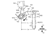
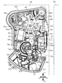
- FIG. 1 is a diagram showing an internal structure of the vehicle door lock device 100 according to the first embodiment.
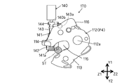
- FIG. 2 is a view of the latch interlocking portion 170 in FIG. 1 viewed from the inside of the vehicle in a state where the latch 112 is at the full latch position.
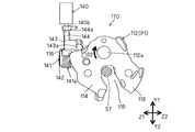
- FIG. 3 is a view of the latch interlocking portion 170 shown in FIG. 2 as viewed from the rear of the vehicle.
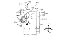
- FIG. 4 is a view of the latch interlocking portion 170 in FIG. 1 viewed from the inside of the vehicle in a state where the latch 112 is at the switching position P2.
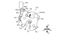
- FIG. 5 is a view of the latch interlocking portion 170 shown in FIG. 4 as viewed from the rear of the vehicle.
- FIG. 2 is a view of the latch interlocking portion 170 in FIG. 1 viewed from the inside of the vehicle in a state where the latch 112 is at the full latch position.
- FIG. 3 is a view of the latch interlocking portion 170 shown in FIG. 2 as viewed
- FIG. 6 is a view of the latch interlocking portion 170 in FIG. 1 viewed from the inside of the vehicle in a state where the latch 112 is at the half latch position P3.
- FIG. 7 is a view of the latch interlocking portion 170 shown in FIG. 6 as viewed from the rear of the vehicle.
- FIG. 8 is a view of the latch interlocking portion 170 in FIG. 1 viewed from the inside of the vehicle in a state where the latch 112 is at the unlatched position P4.
- FIG. 9 is a view of the latch interlocking portion 170 shown in FIG. 8 as viewed from the rear of the vehicle.
- FIG. 10 is a diagram showing an internal structure of the vehicle door lock device 200 according to the second embodiment of the present invention.
- FIG. 10 is a diagram showing an internal structure of the vehicle door lock device 200 according to the second embodiment of the present invention.
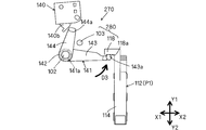
- FIG. 11 is a view of the latch interlocking portion 270 in FIG. 10 viewed from the inside of the vehicle in a state where the latch 112 is at the full latch position P1.
- FIG. 12 is a view of the latch interlocking portion 270 shown in FIG. 11 as viewed from the rear of the vehicle.
- FIG. 13 is a view of the latch interlocking portion 270 in FIG. 10 viewed from the inside of the vehicle in a state where the latch 112 is at the switching position P2.
- FIG. 14 is a view of the latch interlocking portion 270 shown in FIG. 13 as viewed from the rear of the vehicle.
- FIG. 15 is a view of the latch interlocking portion 270 in FIG.
- FIG. 16 is a view of the latch interlocking portion 270 shown in FIG. 15 as viewed from the rear of the vehicle.
- FIG. 17 is a view of the latch interlocking portion 270 in FIG. 10 viewed from the inside of the vehicle in a state where the latch 112 is at the unlatched position P4.
- 18 is a view of the latch interlocking portion 270 shown in FIG. 17 as viewed from the rear of the vehicle. It is the side view seen from the vehicle inner side of the right vehicle door provided with the door lock device for vehicles of a 3rd embodiment of the present invention. It is a perspective view from the vehicle inner back of a door lock device.
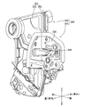
- FIG. 30 is an exploded perspective view of the actuator unit when viewed from a direction different from FIG. 29.
- FIG. 31 is an exploded perspective view of the actuator unit when viewed from a direction different from FIGS. 29 and 30. It is the side view seen from the vehicle inside of the actuator unit which removed and showed the 2nd housing when the latch of the latch unit which omitted illustration was located in an unlatching position. It is a side view similar to FIG.
- FIG. 34 is a cross-sectional view taken along the line XXXIV-XXXIV in FIG.
- FIG. 34 is a cross-sectional view taken along the line XXXV-XXXV in FIG. It is a side view which expands and shows the principal part of FIG. It is the expansion perspective view seen from the downward direction of the same site
- FIG. 34 is a cross-sectional view taken along the line XXVIII-XXXVIII in FIG.
- FIG. 37 is an enlarged side view similar to FIG. 36 when the latch of the latch unit not shown is located at the unlatched position. It is an expansion perspective view similar to FIG.
- FIG. 37 when a latch is located in an unlatching position. It is sectional drawing similar to FIG. 38 when a latch is located in an unlatch position. It is the side view seen from the vehicle inside when a latch of a latch, a door switch, and a switch lever is located in a full latch position. 43 is a rear view of the latch, door switch, and switch lever shown in FIG. 42.
- a vehicle door lock device 100 of the present embodiment shown in FIG. 1 includes a door outer panel (vehicle outer panel) and a door inner panel (vehicle inner panel) of the vehicle door DR. Attached to the area defined by FIG. 1 shows a vehicle door on the right side of the front seat as a typical example of the vehicle door DR.
- the door lock device 100 includes a resin actuator housing 101.
- the actuator housing 101 includes a flat plate portion extending in a flat plate shape along the vehicle longitudinal direction X1 and X2, and components such as a lock mechanism 120 are assembled to the flat plate portion.
- the latch mechanism 110 is for holding the vehicle door DR in a closed state with respect to the vehicle body BD.
- the latch mechanism 110 includes a resin-made latch body 111 fixed to the actuator housing 101, and a latch 112 that can be engaged with and detached from the striker ST fixed to the vehicle body BD.
- the latch body 111 extends in a flat plate shape along a direction intersecting the flat plate portion of the actuator housing 101 (the vehicle left-right direction).
- the latch 112 is rotatably supported by a latch shaft 112a formed upright on the latch body 111, and is configured to rotate in both the meshing direction and the meshing release direction with respect to the striker ST. ing.
- the latch shaft 112a of the latch 112 extends along the vehicle longitudinal direction X1, X2.
- the latch 112 is set at a plurality of positions including an unlatched position that engages with the striker ST, a full latch position where the engagement with the striker ST is released, and a half latch position between the unlatched position and the full latch position.
- the latch 112 is configured to be rotatable about a latch shaft 112a between a full latch position and an unlatching position. The latch 112 is engaged with the striker ST at the full latch position, and the engaged state is maintained, whereby the vehicle door DR is held in a closed state (latched state).
- the latch 112 corresponds to the “latch” of the present invention.
- the door 112 (also referred to as “curtain switch”) 140 that detects the latch position is assigned to the latch 112 in order to control the interior lighting and the like according to the opening / closing state of the vehicle door DR.
- This door switch 140 corresponds to the “door switch” of the present invention.
- the door switch 140 is provided in the actuator housing 101 and is connected to an external terminal for power supply by a resin connector 160 through a pair of metal door switch terminals 140a and 140a. According to the door switch 140, it is detected whether or not the rotation position of the latch 112 is at the full latch position.
- the area of the actuator housing 101 where the door switch terminals 140a and 140a are assembled with electrical components such as the connector 160 is configured as an area where waterproofing is performed. For this reason, by providing the actuator housing 101 with the door switch 140, a non-waterproof switch that is less expensive than the waterproof switch can be used as the door switch 140. In addition, since the wiring from the door switch 140 is integrated into the connector 160 via the door switch terminals 140a and 140a, the connection work on the vehicle side is only one time, which is reasonable.
- the switch lever 141 that engages both the latch 112 and the door switch 140 is interposed.
- the switch lever 141 is configured to be rotatable about a lever shaft 102 extending from the actuator housing 101, and is elastically biased clockwise in FIG. 1 by a lever spring 141a.
- the lever shaft 102 of the switch lever 141 extends from the actuator housing 101 along the vehicle left-right direction orthogonal to the latch shaft 112 a of the latch 112.
- the switch lever 141 is configured to engage with an engagement convex portion 140b for switching the operation state of the door switch 140 between an off state and an on state.
- the lock mechanism 120 functions to set the latch 112 of the latch mechanism 110 to an unlocked state in which the engagement with the striker ST can be released or a locked state in which the engagement with the striker ST cannot be released.
- the lock mechanism 120 includes an active lever 121, an inside open lever 122, an outside open lever 123, an actuator 130, and the like.
- the lock mechanism 120 corresponds to the “lock mechanism” of the present invention.
- the active lever 121 includes an actuator housing between an unlock position where the open link (not shown) is set to the unlock position (first position) and a lock position where the open link is set to the lock position (second position).
- the lever support shaft 121a provided in 101 is pivoted in either direction around the lever support shaft 121a.
- the open link is configured to operate between the unlock position and the lock position by operating the inside open lever 122 or the outside open lever 123.
- the latch mechanism 110 is held in the latched state and the vehicle door DR is not unlocked even if the door opening operation of the door handle is performed. .
- the active lever 121 is configured to rotate (also referred to as “swing” or “rotation”) between the unlock position and the lock position described above by operating the locking / unlocking operation member.
- the locking / unlocking operation member includes a lock knob (not shown) provided inside the vehicle door DR, a key cylinder (not shown) operable from the outside of the vehicle door DR, and a remote controller (not shown) for operating the actuator 130.
- the operation part 121b of the active lever 121 is connected to a lock knob via an operation cable (not shown).
- the engaging portion 121c of the active lever 121 is linked to the key cylinder via a locking control lever 151, a key switch lever 152, an outside locking lever 153, and the like.
- the actuator 130 has an electric motor 131 that operates by operating a remote controller that is one of the locking and unlocking operation members, a worm gear 132 provided on the motor shaft of the electric motor 131, and gear teeth 133 a that engage with the worm gear 132. And an annular wheel gear 133 engaged with the active lever 121.
- the electric motor 131 is connected to an external terminal for power supply by a resin connector 160 through a pair of metal motor terminals 131a and 131a. For this reason, the driving force of the electric motor 131 is transmitted to the wheel gear 133 via the worm gear 132 and the gear teeth 133a, and the active lever 121 rotates as the wheel gear 133 rotates around the center of the circle.
- the latch 112 extends in a flat plate shape on a plane defined by two directions of the vehicle up-down direction Y1, Y2 and the vehicle left-right direction Z1, Z2, and extends substantially in parallel.
- the first locking claw 113 and the second locking claw 114 are provided.
- the region where the locking claws 113 and 114 face each other is configured as a striker receiving portion 115 for receiving the striker ST.
- the latch 112 preferably has a structure formed by coating the surface of a metal material with a resin material.
- the switch lever 141 extends from the cylindrical boss portion 142 attached to the lever shaft 102 toward the latch 112 and from the boss portion 142 toward the door switch 140.
- a second engagement arm 144 The switch lever 141 is engaged with the latch 112 at the arm tip 143a of the first engagement arm 143 while being constantly elastically biased in the direction of the arrow D1 by the lever spring 141a that is a coil spring member.
- the arm front end portion 144a of the two engagement arm 144 is configured to engage with the engagement convex portion 140b of the door switch 140.
- the switch lever 141 presses the latch 112 toward the full latch position P1 by the first engagement arm 143, and the direction in which the first engagement arm 143 presses the latch 112 toward the full latch position P1 (arrow D1).
- Direction is elastically biased by a lever spring 141a.
- the switch lever 141 and the first engagement arm 143 correspond to the “switch lever” and the “engagement arm” of the present invention, respectively.
- the lever spring 141a corresponds to the “lever spring” of the present invention.
- the engagement surface with the object is configured to have a curved surface shape.
- the latch 112 includes a first engagement surface 116 and a second engagement surface 117 that are used for engagement with the first engagement arm 143 of the switch lever 141.
- the first engagement surface 116 is configured by using a latch outer peripheral cam surface located on the opposite side of the striker receiving portion 115 with the latch shaft 112a sandwiched among the outer peripheral surfaces defining the latch outline of the latch 112.
- the second engagement surface 117 is configured by using one latch side surface near the lever shaft 102 out of both side surfaces of the latch extending along the rotation surface of the latch 112.
- the first engagement surface 116 and the second engagement surface 117 here correspond to the “first engagement surface” and the “second engagement surface” of the present invention, respectively.
- the latch 112 When the latch 112 is at the full latch position P1 in FIGS. 2 and 3, the latch 112 is positioned at the full latch position P1 by engagement with a pole (not shown). Rotation in the direction D2 in 3) is prevented. That is, the rotation of the latch 112 in the unlocking direction (unlatching direction) is prevented at the full latch position P1. As a result, the vehicle door DR is held in a fully closed state.
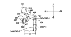
- the horizontal distance in the vehicle front-rear direction X1, X2 of the first engagement arm 143 of the switch lever 141 is La.
- This horizontal distance La is the distance L in the vehicle longitudinal direction X1, X2 between the lever shaft 102 and the second engagement surface 117 that is the side surface (latch back surface) of the both sides of the latch 112 facing the switch lever 141.
- Exceed. Accordingly, the switch lever 141 comes into contact with the first engagement surface 116 of the latch 112 from above at the arm tip 143a of the first engagement arm 143 by the elastic biasing force of the lever spring 141a. Further, the switch lever 141 does not press the engagement convex portion 140b of the door switch 140 from the off position to the on position at the arm tip portion 144a of the second engagement arm 144. For this reason, when the latch 112 is in the full latch position P1, the operation state of the door switch 140 is not turned on.
- the latch 112 rotates from the full latch position P1 to the unlatch position (also referred to as “latch release position” or “latch open position”) P4 (that is, the half latch position P3) around the latch shaft 112a.
- the switch lever 141 is centered on the lever shaft 102 against the elastic biasing force of the lever spring 141a because the arm tip 143a of the first engagement arm 143 is pushed up by the first engagement surface 116 of the latch 112. Is rotated in the direction opposite to the arrow D1 direction in FIG. As shown in FIGS.
- the door switch The switch lever 141 rotates in conjunction with the latch 112 so that the operation state of 140 is switched from the off state to the on state. That is, since the switch lever 141 presses the engagement convex portion 140b of the door switch 140 from the off position to the on position at the arm tip 144a of the second engagement arm 144, the operation state of the door switch 140 is turned on. . As a result, for example, the interior lighting is turned on. In this case, the switching position P2 is set between the full latch position P1 and the half latch position P3.
- the horizontal distance Lb of the switch lever 141 is longer than the interval L although it is shorter than the horizontal distance La. Therefore, the arm tip 143a of the first engagement arm 143 slides on the first engagement surface 116 of the latch 112 toward the vehicle front X1.
- the latch 112 further rotates about the latch shaft 112a from the switching position P2 toward the unlatched position P4 to the half latch position P3, so that the switch lever 141 is moved to the first position.
- the arm tip 143a of the engagement arm 143 is pushed up by the first engagement surface 116 of the latch 112, and is opposite to the arrow D1 direction in FIG. 6 centering on the lever shaft 102 against the elastic biasing force of the lever spring 141a.
- the switch lever 141 is brought into sliding contact with the engagement convex portion 140b of the door switch 140 at the arm front end portion 144a of the second engagement arm 144, whereby the operation state of the door switch 140 is maintained in the on state.
- the horizontal distance Lc of the switch lever 141 slightly exceeds the distance L. Accordingly, the arm tip 143a of the first engagement arm 143 moves from the first engagement surface 116 of the latch 112 to the corner 116a (the boundary between the first engagement surface 116 and the second engagement surface 117). To do.
- the latch 112 further rotates from the half latch position P3 to the unlatch position P4 about the latch shaft 112a, so that the horizontal distance Ld of the switch lever 141 is the horizontal distance Lc. Slightly below and substantially coincides with the interval L.
- the engagement point between the arm tip 143a of the first engagement arm 143 of the switch lever 141 and the latch 112 is switched from the first engagement surface 116 to the second engagement surface 117, and this first engagement arm
- the arm tip 143a of 143 slides on the second engagement surface 117. That is, the rotation position of the switch lever 141 itself hardly changes, and only the relative position of the latch 112 with respect to the switch lever 141 changes.
- the operating state of the door switch 140 is maintained in the on state.
- the switch lever 141 rotates in conjunction with the latch 112 so that the operating state of the door switch 140 is maintained in the ON state when the latch 112 is located in the region from the switching position P2 to the unlatching position P4.
- the arm tip 143a of the first engagement arm 143 shifts to the state where it slides on the second engagement surface 117, it is possible to prevent the elastic biasing force of the lever spring 141a acting on the latch 112 from increasing.
- the first engagement arm of the switch lever 141 is in an intermediate position (switching position P2 or half-latch position P3) while the latch 112 is rotating from the full latch position P1 to the unlatching position P4.
- the region where the arm tip 143 a of 143 engages shifts from the first engagement surface 116 of the latch 112 to the second engagement surface 117. Therefore, the latch 112 rotates in the region from the switching position P2 to the unlatching position P4 as compared with the first rotation state in which the latch 112 rotates in the region from the full latch position P1 to the switching position P2.
- the ratio of the amount of rotation of the switch lever 141 to the amount of rotation of the latch 112 is lower in the second rotation state.
- the first engagement surface 116 and the second engagement surface 117 of the latch 112 constitute a lever rotation amount adjustment mechanism 180 that adjusts the rotation amount of the switch lever 141.
- This lever rotation amount adjustment mechanism 180 corresponds to the “lever rotation amount adjustment mechanism” of the present invention.
- the first engagement surface 116 rotates the latch 112 when the arm tip 143a of the first engagement arm 143 slides against the elastic biasing force of the lever spring 141a in the first rotation state of the latch 112.
- the latch 112 is provided so that the ratio of the amount of rotation of the switch lever 141 to the amount of movement is constant.
- the second engagement surface 117 latches when the arm tip 143a of the first engagement arm 143 slides against the elastic biasing force of the lever spring 141a in the second rotation state of the latch 112.
- the latch 112 is provided so that the ratio of the rotation amount of the switch lever 141 to the rotation amount of 112 is lower than that in the first rotation state.
- the lever rotation amount adjusting mechanism 180 when the latch 112 shifts from the first rotation state to the second rotation state, the rotation amount of the switch lever 141 that rotates in conjunction with the latch 112 is set. It can be lower than before the transition. Therefore, after the latch 112 reaches the switching position P2 from the full latch position P1 and the operation state of the door switch 140 changes from the off state to the on state, the switch lever can be rotated even if the latch 112 further rotates toward the unlatch position P4. It is possible to prevent the 141 from rotating more than necessary. In this case, there is no need to rotate the switch lever 141 by the same amount of rotation as before the door switch 140 is turned on after the operation state of the door switch 140 is turned on. Can be prevented from becoming larger.
- the vehicle door lock device 100 can be reduced in size.
- the switch lever from the switching position P2 to the unlatching position P4 is used. 141 rotates in vain.
- the switch lever 141 is largely rotated from the switching position P2 to the unlatching position P4.
- the lever rotation amount adjustment mechanism 180 is utilized by using the first engagement surface 116 and the second engagement surface 117 provided on the latch 112 which is an existing component without increasing the number of components. And the product cost of the door lock device 100 can be prevented from increasing.
- one of the latch side surfaces used as the second engagement surface 117 in each part of the latch 112 is in a positional relationship facing the arm tip 143a of the first engagement arm 143, and the latch outer peripheral cam surface (first The outer contour of the latch 112 can be prevented from becoming larger than when the outer peripheral surface continuous from the first engagement surface is used as the second engagement surface 117.
- the switch lever 141 In the second rotation state of the latch 112, it is preferable to adopt a configuration in which the switch lever 141 is slightly rotated or a configuration in which the rotation amount of the switch lever 141 is zero (a state in which the switch lever 141 is not rotated at all). In the case of this configuration, it is necessary to regulate the rotation of the switch lever 141 with respect to the latch 112 that rotates toward the unlatch position P4 at the position where the operation state of the door switch 140 is turned on. Since it is not necessary to use a new member such as a stopper as a restricting means for restricting the rotation of 141, an increase in the number of parts can be prevented.
- a member such as a stopper can be used as a restricting means for restricting the rotation of the switch lever 141 as necessary.
- the door lock device 200 of the second embodiment as shown in FIG. 10 may be employed instead of the door lock device 100 described above.
- This door lock device 200 is substantially different from the door lock device 100 only in the structure of the latch interlocking portion 270 and the lever rotation amount adjusting mechanism 280. Therefore, in the following description, only the structure of the latch interlocking portion 270 and the lever rotation amount adjusting mechanism 280 will be described in detail with reference to FIGS. 11 to 18, and description of other components will be omitted.
- the latch interlocking portion 270 functions to operate the door switch 140 and the switch lever 141 configured as described above in conjunction with the latch 112.
- the latch 112 includes a latch extension 118 extending from the latch body toward the vehicle front X1.
- a lower surface 118a of the latch extending portion 118 located on the latch shaft 112a side is configured as an engaging surface with which the arm tip 143a of the first engaging arm 143 of the switch lever 141 is engaged.
- the switch lever 141 is engaged with the latch 112 at the arm tip portion 143a of the first engagement arm 143 while being constantly elastically biased in the direction of the arrow D3 by the lever spring 141a, and the second engagement arm 144.
- the arm tip 144a is configured to be engaged with the engagement convex portion 140b of the door switch 140. That is, the switch lever 141 presses the latch 112 toward the unlatched position P4 by the first engaging arm 143, and the direction in which the first engaging arm 143 presses the latch 112 toward the unlatched position P4 (arrow D3). Direction) is elastically biased by a lever spring 141a.
- the latch 112 reaches a half latch position P3 (described later) during the rotation from the full latch position P1 to the unlatching position P4, the operation of the switch lever 141 in the direction of arrow D3 is formed upright on the actuator housing 101.
- the stopper 103 is configured to be blocked.
- the latch 112 Since the latch 112 is positioned at the full latch position P1 by engagement with a pawl (not shown) when in the full latch position P1 in FIGS. 11 and 12, the latch 112 is rotated in the clockwise direction around the latch shaft 112a (see FIG. Rotation in the direction D4 in 12) is prevented. That is, the rotation of the latch 112 in the unlocking direction (unlatching direction) is prevented at the full latch position P1. As a result, the vehicle door DR is held in a fully closed state.
- the switch lever 141 When the latch 112 is in the full latch position P1, the switch lever 141 is lowered to the lower surface 118a of the latch extension 118 of the latch 112 at the arm tip 143a of the first engagement arm 143 by the elastic biasing force of the lever spring 141a. Abut. Further, the switch lever 141 does not press the engagement convex portion 140b of the door switch 140 from the off position to the on position at the arm tip portion 144a of the second engagement arm 144. For this reason, when the latch 112 is in the full latch position P1, the operation state of the door switch 140 is not turned on.
- the switch lever 141 follows the operation of the latch extending portion 118 while moving the lever. According to the elastic biasing force of the spring 141a, the lever shaft 102 is rotated in the direction of arrow D3 in FIG. As shown in FIGS. 13 and 14, when the latch 112 is rotated to the switching position P2 in the middle of being rotated to the unlatched position P4 (that is, the half latch position P3), the operating state of the door switch 140 is changed. The switch lever 141 rotates in conjunction with the latch 112 so as to switch from the off state to the on state.
- the switching position P2 is set between the full latch position P1 and the half latch position P3. At this time, the arm tip 143a of the first engagement arm 143 slides on the lower surface 118a of the latch extension 118 of the latch 112 toward the vehicle front X1.
- the latch 112 further rotates about the latch shaft 112a from the switching position P2 toward the unlatch position P4 to the half latch position P3, so that the switch lever 141 is moved to the lever spring. It rotates in the direction of arrow D3 in FIG. 15 around the lever shaft 102 in accordance with the elastic biasing force 141a.
- the switch lever 141 is brought into sliding contact with the engagement convex portion 140b of the door switch 140 at the arm front end portion 144a of the second engagement arm 144, whereby the operation state of the door switch 140 is maintained in the on state.
- the movement of the switch lever 141 in the direction of arrow D3 is blocked by the stopper 103 as shown in FIG. 15, and the arm front end 143a of the first engagement arm 143 as shown in FIG.
- the engagement with the lower surface 118a of the latch extension 118 is released.
- the switch lever 141 is moved by the elastic biasing force of the lever spring 141a.
- the state where the first engagement arm 143 is pressed against the stopper 103 is maintained.
- the switch lever 141 is held at the position as it was at the half latch position P3. That is, the rotation position of the switch lever 141 itself does not change at all, and only the relative position of the latch 112 with respect to the switch lever 141 changes.
- the operating state of the door switch 140 is maintained in the on state.
- the switch lever 141 rotates in conjunction with the latch 112 so that the operating state of the door switch 140 is maintained in the ON state when the latch 112 is located in the region from the switching position P2 to the unlatching position P4.
- the arm tip of the first engagement arm 143 of the switch lever 141 is in an intermediate position (half latch position P3) where the latch 112 is rotating from the full latch position P1 to the unlatching position P4.
- the region in which the portion 143 a engages shifts from the lower surface 118 a of the latch extending portion 118 of the latch 112 to the stopper 103. Therefore, the latch 112 rotates in the region from the switching position P2 to the unlatching position P4 as compared with the first rotation state in which the latch 112 rotates in the region from the full latch position P1 to the switching position P2.
- the latch extension 118 and the stopper 103 of the latch 112 constitute a lever rotation amount adjustment mechanism 280 that adjusts the rotation amount of the switch lever 141.
- This lever rotation amount adjustment mechanism 280 corresponds to the “lever rotation amount adjustment mechanism” of the present invention.
- the same operation effects as those obtained when the lever rotation amount adjustment mechanism 180 is used can be obtained.
- the lever rotation amount adjusting mechanism is constructed using only the latch extending portion 118, it is necessary to extend the latch extending portion 118 to the vehicle left side Z1 in FIG.
- the lever rotation amount adjusting mechanism is constructed by combining the stopper 103 with the latch extending portion 118, it is possible to prevent the latch 112 from becoming large.
- a vehicle door 310 shown in FIG. 19 is a side door on the right side of the vehicle, and a front end portion of the vehicle door 310 is supported so as to be rotatable about a vertical rotation axis with respect to a vehicle body (not shown).
- the vehicle door 310 is rotatable in a horizontal direction with respect to the vehicle body between an open position that completely opens an opening formed on a side surface of the vehicle body and a closed position that closes the opening.
- the “front-rear direction” and “left-right direction (inside / outside direction)” relating to the vehicle door 310 in the following description are directions based on the case where the vehicle door 310 is located at the closed position.
- the vehicle door 310 includes a door main body portion 311 constituting the lower half portion thereof, and a door sash 312 provided in the upper half portion thereof.
- the door main body 311 includes an outer panel (not shown) constituting the outer surface of the door main body 311, an inner panel (not shown) fixed to the inner side surface of the outer panel, and an inner panel fixed to the inner side surface of the inner panel. And a resin trim 313 constituting the inner surface of the portion 311.
- An outside handle 317 is rotatably supported on the outer panel, and an inside handle 318 is rotatably supported on the trim 313.
- the outside handle 317 and the inside handle 318 are rotatable between an initial position and a latch release position, and both are urged to rotate toward an initial position by an urging means (not shown).
- a lock knob 319 is provided at the upper end of the trim 313 so as to be slidable in the vertical direction.
- the lock knob 319 is slidable with respect to the trim 313 between an unlock position (position in FIG. 19) and a lock position (not shown) located below the unlock position.
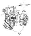
- a door lock device 320 that is located between the outer panel and the inner panel and is partially exposed at the rear end surface of the vehicle door 310. As shown in FIGS. 20 and 21, etc., the door lock device 320 is an integrated latch unit 325 and actuator unit 350.
- the latch unit 325 includes a latch housing 326 (housing) including a first housing 327 and a second housing 335.
- a striker entry groove 328 extending from the left end surface (the vehicle inner end surface) of the first housing 327 to the right side is recessed.
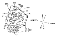
- a mounting recess 329 is provided on the rear surface of the first housing 327 so as to be continuous (communicated) with the striker entry groove 328 in a manner crossing the striker entry groove 328.
- a through hole 330 that penetrates the first housing 327 in the front-rear direction is formed on the bottom surface of the mounting recess 329. As illustrated, the through-hole 330 is a long hole extending in the vertical direction.
- a latch-side waterproof wall 331 protrudes from the bottom surface and the inner peripheral surface of the mounting recess 329.
- a striker entry groove 336 extending in the left-right direction is formed in the rear portion and the left side portion of the second housing 335.
- a latch 340, a pole 345, and a lift lever 348 are rotatably supported by the first housing 327.
- the latch 340 is disposed in the mounting recess 329, and is supported so as to be rotatable around a rotation shaft provided on a support wall 329a which is the bottom surface of the mounting recess 329.
- the latch 340 does not hold a striker (not shown) fixed to the vehicle body (does not hold the closed state of the vehicle door 310), and a full latch position that can hold the striker (holds the closed state of the vehicle door 310). Between the first housing 327 and the first housing 327.
- the latch 340 includes a first locking claw 341 and a second locking claw 342, and a striker receiving groove 343 is formed between the first locking claw 341 and the second locking claw 342.
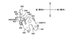
- a first engagement surface 340 a and a second engagement surface 340 b are formed on the outer surface of the latch 340.
- the first engagement surface 340a and the second engagement surface 340b constitute a lever rotation amount adjustment mechanism 340c that adjusts the rotation amount of a switch lever 420 described later.
- the first engagement surface 340 a is formed on a part of the outer peripheral surface of the latch 340.
- the second engagement surface 340 b is formed on a part of the front surface of the latch 340.
- the pole 345 is disposed in the mounting recess 329 below the latch 340.
- the pole 345 passes through the first housing 327 in the front-rear direction and is fixed to a rotation shaft 344 that can rotate relative to the first housing 327. Therefore, the pawl 345 is engaged with the latch 340 located at the full latch position together with the rotation shaft 344 and the engagement position (the position shown in FIG. 26) for holding the latch 340 in the full latch position, and the non-separated position from the latch 340. It can be rotated between engagement positions (positions in FIGS. 22 and 23). Further, the latch 340 is always urged to rotate toward the unlatched position and the pole 345 is always urged to rotate toward the engaging position by the urging force of the urging means.
- a lift lever 348 facing the front surface of the first housing 327 is disposed in front of the first housing 327.
- the lift lever 348 is fixed to the front portion of the rotating shaft 344 protruding forward from the front surface of the first housing 327. That is, the lift lever 348 rotates together with the rotation shaft 344 and the pole 345.
- the pawl 345 When the latch 340 located at the unlatched position rotates to the full latch position against the urging force of the urging means while engaging with the striker, the pawl 345 is located at the engaging position by the urging force of the urging means and is latched 340. Engage with. As a result, the latch mechanism having the latch 340 and the pole 345 enters a “latch state” in which the latch 340 holds the striker. On the other hand, when the pole 345 is rotated to the non-engagement position side against the urging force of the urging means, the latch 340 can be rotated to the unlatch position side. Therefore, the latch mechanism is in an “unlatched state” where the striker can be released.
- the first housing 327 that supports the latch 340, the pole 345, and the lift lever 348 is covered with the second housing 335 from the rear, and the first housing 327 and the second housing 335 are fixed to complete the latch unit 325. (Refer to FIG. 20, FIG. 21, etc.).
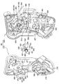
- the actuator unit 350 has an actuator housing 351 (housing) including a first housing 352 and a second housing 375.
- the first housing 352 is an integrally molded product made of resin.
- a latch unit connection portion 353 is formed at the rear portion of the first housing 352.
- the first housing 352 includes a rotation shaft 354 that is positioned below the latch unit connection portion 353 and extends rearward.
- a plurality of rotating shafts 355, 356, 357, 358, 359 each having an axis extending toward the second housing 375 are provided on the surface of the first housing 352 facing the second housing 375.
- the rotation shaft 355 has a cylindrical shape with an open end surface.
- a switch-side waterproof wall 361 projects from the surface of the first housing 352 facing the second housing 375 toward the second housing 375 side.
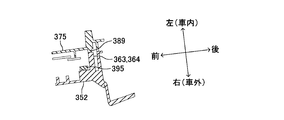
- the switch-side waterproof wall 361 is integrally provided with a rear wall portion 362 extending substantially in the vertical direction and a bottom wall portion 363 extending substantially horizontally from the lower end of the rear wall portion 362 toward the front.
- a cutout portion 365 is formed in the bottom wall portion 363.
- a portion of the bottom wall portion 363 that is located immediately after the notch portion 365 constitutes a rear facing portion 364 that extends in the left-right direction.
- a lever guide projection 368 (inner wall) is provided on the surface of the first housing 352 facing the second housing 375 so as to project toward the second housing 375 side.
- the lever guide protrusion 368 has an arc shape centered on the axis of the rotation shaft 358.
- a lower waterproof wall 370 projects from the surface of the first housing 352 facing the second housing 375 toward the second housing 375 side.
- the lower waterproof wall 370 is located in front of the lever guide protrusion 368.
- the lower waterproof wall 370 has an arc shape centered on the axis of the rotation shaft 358 and substantially the same diameter as the lever guide protrusion 368.
- a spring locking portion 372 located in the vicinity of the rotation shaft 358 is provided projecting toward the second housing 375 side.
- the second housing 375 is an integrally molded product made of resin.
- a latch unit connection portion 376 is formed at the rear portion of the second housing 375.
- a fitting protrusion 378 is provided on the surface of the second housing 375 facing the first housing 352.
- bearing portions 379, 380, 381, and 382 are formed on the surface of the second housing 375 that faces the first housing 352.
- the bearing portion 379 and the bearing portion 382 are concave portions formed in the second housing 375, and the bearing portion 380 and the bearing portion 381 have a cylindrical shape with an open end surface.
- a lever guide projection 383 (inner wall) is provided on the surface of the second housing 375 facing the first housing 352 so as to project toward the first housing 352 side.
- the lever guide protrusion 383 has an arc shape centered on the axis of the bearing portion 381. As shown in FIGS. 29 and 31, the lever guide protrusion 383 is integrally provided with a wide portion 384 that forms the rear portion thereof, and a narrow portion 385 that forms the front portion and is narrower than the wide portion 384. Yes. Further, on the surface of the second housing 375 facing the first housing 352, a switch-side waterproof wall 387 located directly above the lever guide projection 383 is provided so as to project toward the first housing 352 side. The switch-side waterproof wall 387 is integrally provided with a rear wall portion 388 extending substantially vertically and a bottom wall portion 389 extending substantially horizontally from the lower end of the rear wall portion 388 toward the front.
- a door switch 393 (a courtesy switch, a switch), which is an electrical component, is fixed to a surface of the first housing 352 facing the second housing 375.
- the door switch 393 includes a main body portion 394 and a pressed convex portion 395 (an engaging convex portion) that protrudes downward from the lower end surface of the main body portion 394 and can rotate relative to the main body portion 394.
- the pressed convex portion 395 can rotate around a rotation axis in the left-right direction with respect to the main body portion 394. Specifically, it can be rotated between an off position shown in FIGS. 29 to 31, 33, 36, and 37 and an on position shown in FIGS.
- a connector 397 is fixed to a surface of the first housing 352 facing the second housing 375.
- a door switch terminal 398 that connects the door switch 393 and the connector 397 is fixed to a surface of the first housing 352 facing the second housing 375.
- Connector 397 is connected to an ECU (not shown) via a cable (not shown). Further, the ECU is connected to an illumination device (not shown) provided on the inner surface (for example, the ceiling surface) of the vehicle.
- an outside open lever 417 is rotatably supported on the first housing 352 (rotation shaft 354 thereof), and an open link is provided on a support shaft 418 protruding from the outside open lever 417.
- 400 is rotatably supported.
- an urging spring 401 is provided between the support shaft 418 and the open link 400. This urging spring 401 urges the open link 400 to rotate toward the unlock position.
- the active lever 403 is rotatably supported on the rotation shaft 355 of the first housing 352.
- the active lever 403 includes an unlock position (the position shown in FIGS. 32 and 33) that allows the open link 400 to be located at the unlock position, and a lock position (not shown) that positions the open link 400 at the lock position. Between the two.
- the active lever 403 and the lock knob 319 are linked by an operation wire (not shown).
- the lock knob 319 is located at the lock position
- the active lever 403 is located at the lock position, and as a result, the open link 400 is located at the lock position.
- the lock knob 319 moves from the lock position to the unlock position
- the active lever 403 rotates to the unlock position by the moving force of the lock knob 319, and the open link 400 moves to the unlock position.
- a locking control lever 405 is rotatably supported on the rotation shaft 359 of the first housing 352.
- An outside locking lever 409 is linked to a key cylinder (not shown) provided on the outer panel or outside handle 317.
- the key switch lever 411 is linked to the locking control lever 405 and the outside locking lever 409.
- an electric motor 412 is fixed to the surface of the first housing 352 facing the second housing 375.
- a motor terminal 413 that connects the electric motor 412 and the connector 397 is fixed to a surface of the first housing 352 facing the second housing 375.
- the electric motor 412 operates by operating a remote controller that is one of the locking / unlocking operation members.
- a worm gear 414 is fixed to the output shaft of the electric motor 412.
- a disc-shaped wheel gear (not shown) is rotatably supported on the rotation shaft 357 of the first housing 352. The gear teeth formed on the outer peripheral surface of the wheel gear mesh with the worm gear 414. Further, the wheel gear is linked to the active lever 403.
- An inside open lever 416 is rotatably supported on the rotation shaft 356 of the first housing 352.
- the inside open lever 416 and the inside handle 318 are linked by an operation wire.
- the inside handle 318 When the inside handle 318 is located at the initial position, the inside open lever 416 is located at the non-pressing position. At this time, the inside open lever 416 does not exert any force on the open link 400.
- the inside handle 318 moves from the initial position to the latch release position, the inside open lever 416 moves to the pressing position. If the inside open lever 416 moves to the pressing position when the open link 400 is located at the unlock position, the inside open lever 416 presses the open link 400, so that the open link 400 rotates in a predetermined direction.
- an outside open lever 417 is rotatably supported on the rotation shaft 354.
- the outside open lever 417 is connected to the outside handle 317 via a rod.
- the outside handle 317 When the outside handle 317 is located at the initial position, the outside open lever 417 is located at the non-pressing position. At this time, the outside open lever 417 does not exert any force on the open link 400.
- the outside handle 317 moves from the initial position to the latch release position, the outside open lever 417 moves to the pressing position.
- the outside open lever 417 moves to the pressing position when the open link 400 is located at the unlock position, the outside open lever 417 presses the open link 400, so that the open link 400 rotates in the predetermined direction.
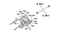
- a switch lever 420 is rotatably supported on a rotation shaft 358 (lever shaft) of the first housing 352.
- the switch lever 420 has a cylindrical boss portion 421 that is rotatably attached to the rotation shaft 358.
- the switch lever 420 has a first engagement arm 422 extending from the boss portion 421 in the radial direction of the boss portion 421.
- the distal end portion of the first engagement arm 422 is configured by an arm distal end portion 423 having a substantially spherical shape.
- a first waterproof wall 424 (hole closed side portion) having an arc shape centering on the axis of the boss portion 421 is projected.
- a spring locking portion 425 is provided so as to be positioned on the boss portion 421 side with respect to the first waterproof wall 424.
- the second engagement arm 427 is counterclockwise (forward) from the first engagement arm 422 from the left side surface of the intermediate portion of the first engagement arm 422.
- the boss portion 421 extends in the radial direction in a positioned manner. That is, the second engagement arm 427 is offset to the left with respect to the first engagement arm 422.
- a second waterproof wall 428 (hole closed side portion) that has an arc shape centered on the axis of the boss portion 421 and is located on the outer peripheral side of the first waterproof wall 424 is provided at the distal end portion of the second engagement arm 427. Projected.
- a lever spring 430 is attached to the rotation shaft 358.
- the lever spring 430 includes a pair of locking pieces 431 and 432. As shown in FIGS. 36 and 39, one locking piece 431 is locked to the spring locking portion 425 of the switch lever 420. The other locking piece 432 is locked to the spring locking portion 372 of the first housing 352.
- the lever spring 430 is locked to the first housing 352 and the switch lever 420 (spring locking portion 425)
- the lever spring 430 is in an elastically deformed state.
- the switch lever 420 is always urged to rotate clockwise in FIGS. 36 and 39 by the urging force generated by the lever spring 430.
- the actuator unit 350 is completed when the first housing 352 and the second housing 375 are fixed to each other with the fixing means in a state where the opposing portions of the outer peripheral edges are in contact with each other.
- the fitting protrusion 378 of the second housing 375 is fitted to the turning shaft 355 of the first housing 352, and the turning shafts 356, 357, 358, 359 of the first housing 352 are further fitted. Is fitted to the bearing portions 379, 380, 381, 382 of the second housing 375. Further, as shown in FIGS.
- the lever guide projection 368 and the lower waterproof wall 370 of the first housing 352 and the wide portion 384 of the lever guide projection 383 of the second housing 375 are connected to the switch lever movement allowance groove 386 (
- the first engagement arm 422 of the switch lever 420 is rotatably positioned in the switch lever movement allowance groove 386 while forming a gap.
- the rear wall portion 362 of the switch-side waterproof wall 361 of the first housing 352 and the rear wall portion 388 of the switch-side waterproof wall 387 of the second housing 375 are in contact with each other, and as shown in FIG.
- the bottom wall portion 363 of the wall 361 and the bottom wall portion 389 of the switch-side waterproof wall 387 are in contact with each other. As shown in FIG.
- the bottom wall portion 363 (rear facing portion 364) is located immediately after the pressed convex portion 395 of the door switch 393.
- the second engagement arm 427 of the switch lever 420 is located on the right side of the narrow width portion 385 of the lever guide projection 383 and immediately before the wide width portion 384.
- the first waterproof wall 424 of the switch lever 420 is located on the inner peripheral side of the lever guide protrusion 368, the lower waterproof wall 370, and the lever guide protrusion 383, and the switch lever.
- the second waterproof wall 428 of 420 is located on the outer peripheral side of the lever guide protrusion 368, the lower waterproof wall 370, and the lever guide protrusion 383. Further, an opening surrounded by the latch unit connection portion 353 of the first housing 352 and the latch unit connection portion 376 of the second housing 375 is formed on the rear surface of the actuator housing 351 (see FIGS. 21 and 27). And the front-end
- the active lever 403, the inside open lever 416, the outside open lever 417, the electric motor 412, the worm gear 122, and the wheel gear of the actuator unit 350 are components of the lock mechanism.
- the door The locking device 320 is completed.
- the tip end portion (upper end) of the open link 400 of the actuator unit 350 is obtained. Part) faces the lift lever 348 of the latch unit 325. Further, as shown in FIGS.
- the latch unit 325 is further provided with a striker entry groove 328 and a striker entry groove 336. Therefore, for example, when the user performs a car wash when the vehicle door 310 is in an open state, a liquid (for example, water, hereinafter referred to as “water”) used during the car wash is a striker entry groove 328 and a striker entry groove 336. May enter the latch unit 325 via the through hole 330, and may further enter the actuator unit 350 via the through hole 330. Inside the actuator unit 350, a door switch 393, which is an electrical component, is provided. If water adheres to the door switch 393, the door switch 393 may malfunction. Therefore, it is necessary to suppress water that has entered the interior of the latch unit 325 from adhering to the door switch 393. However, in the present embodiment, as described below, there is a very low possibility that water will adhere to the door switch 393.
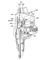
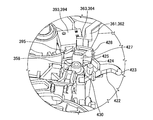
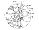
- the latch 340 When the vehicle door 310 is in the open state, the latch 340 is positioned at the unlatched position by the urging force of the urging means. As shown in FIGS. 22, 23, and 24, the latch 340 overlaps almost the entire through-hole 330 when viewed in the thickness direction of the support wall 329 a (the front-rear direction when the vehicle door 310 is closed). . That is, the second locking claw 342 of the latch 340 overlaps with the whole except for the upper end portion of the through hole 330. Further, as apparent from FIGS.
- the two waterproof walls 428 overlap with at least a part of the through hole 330.
- the second waterproof wall 428 of the switch lever 420 contacts the pressed convex portion 395 of the door switch 393 from below.
- the second waterproof wall 428 covers the pressed protrusion 395 from below.
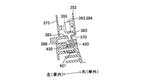
- the first waterproof wall 424 of the switch lever 420 includes the lever guide protrusion 368, the lower waterproof wall 370, and the lever guide protrusion 383.
- the second waterproof wall 428 of the switch lever 420 is positioned on the outer peripheral side of the lever guide protrusion 368, the lower waterproof wall 370, and the lever guide protrusion 383.
- the first waterproof wall 424 and the second waterproof wall 428 form the switch lever movement allowance groove 386. It overlaps with a part.
- the switch lever movement is allowed through the gap between the first waterproof wall 424 and the switch lever movement allowance groove 386. After passing through the groove 386 upward, it is necessary to further pass through the gap between the switch lever movement allowance groove 386 and the second waterproof wall 428 toward the door switch 393 side. Therefore, the actuator unit 350 has a structure in which water does not easily pass through the switch lever movement allowance groove 386 as compared with the case where the switch lever 420 does not include the first waterproof wall 424 and the second waterproof wall 428. Therefore, the latch 340 and the switch lever 420 positioned at the unlatched position can suppress the water that has entered the latch unit 325 from passing through the through hole 330 toward the door switch 393 in the actuator unit 350.
- the lever guide protrusion 368 of the first housing 352 and the wide waterproof portion 384 of the lower waterproof wall 370 and the lever guide protrusion 383 of the second housing 375 are included in the latch unit 325. Between the through hole 330 and the door switch 393. Therefore, even if the water passes through the through hole 330 of the support wall 329a and goes to the door switch 393 side, the lever guide protrusion 368, the lower waterproof wall 370, and the wide portion 384 cause the water to pass through the door switch 393 side. Can be effectively suppressed.
- the bottom wall portion 363 (rear facing portion 364) of the switch side waterproof wall 361 contacts the bottom wall portion 389 of the switch side waterproof wall 387, and the rear facing portion 364 is covered by the door switch 393. It is located immediately after the pressing projection 395. Therefore, even if water passes through the through-hole 330 of the support wall 329a and travels toward the door switch 393 side, the switch-side waterproof wall 361 (bottom wall portion 363) and the switch-side waterproof wall 387 (bottom wall portion 389). ) Can effectively prevent water from adhering to the door switch 393.
- the upper portion of the mounting recess 329 of the first housing 327 position above the striker entry groove 328.
- the most part of the communication hole 329b (opening for communicating the upper part of the mounting recess 329 and the striker entry groove 328), which is the end of the striker entry groove 328 side, is closed by the latch 340.
- the gap 329b1 is formed only at the end of the communication hole 329b. Therefore, when the vehicle is washed, there is a possibility that water may go through the gap 329b1 toward the through hole 330 located above the striker entry grooves 328 and 336.
- the through hole 330 is located above the striker entry grooves 328 and 336 and the gap 329b1. Furthermore, as shown in FIG. 23, the latch-side waterproof wall 331 is located between the gap 329 b 1 and the through hole 330. Therefore, even if water passes through the gap 329b1 and enters the mounting recess 329, the latch-side waterproof wall 331 can effectively suppress the water from moving toward the through hole 330.
- the door switch 393 is located above the through hole 330 of the latch unit 325. Therefore, even if water enters the actuator unit 350 from the through hole 330, there is little possibility that this water will go to the door switch 393 side.
- the present invention is not limited to the above exemplary embodiment, and various applications and modifications are possible.
- each of the following embodiments to which the above embodiment is applied can be implemented.
- the arm tips 143a and 423 of the first engagement arms 143 and 422 of the switch levers 141 and 420 are in the middle of the rotation of the latches 112 and 340 from the full latch position P1 to the unlatching position P4.
- the region where the first and second engagement surfaces 116 and 340a of the latches 112 and 340 shift from the first engagement surfaces 116 and 340a to the second engagement surfaces 117 and 340b has been described.
- the arm tip portions 143a and 423 of the first engagement arms 143 and 422 are always in the first engagement of the latches 112 and 340.
- a configuration that engages with the surfaces 116 and 340a may be employed.
- the door lock devices 100 and 200 may be configured to be switched to each other.
- the door lock device 100, 200, 320 may be provided on the vehicle body side, and the striker may be provided on the vehicle door side.
- the essential structure of the door lock device 100, 200, 320 can be applied to each vehicle door of the vehicle.
- the door lock devices 100, 200, 320 according to the present invention are essentially used for left and right doors for a front seat of a vehicle, left and right doors for a rear seat of a vehicle, and a door (back door) of a rear portion of the vehicle. Structure can be applied.
- the rotation direction with respect to the vehicle body of the door to which the door lock device 100, 200, 320 is applied may be not only the horizontal direction but also the vertical direction.
- the one corresponding to the latch housing 326 and the actuator housing 351 may be integrally formed to constitute one housing.
- the second waterproof wall 428 presses the pressed convex portion 395 of the door switch 393 to turn on the door switch 393, and the latch 340 is switched to the switching position P2 and the unlatched position.
- the door switch 393 may be turned off when the second waterproof wall 428 is separated from the pressed convex portion 395 of the door switch 393 when positioned between P4 and P4.
- the entire through-hole 330 and the latch 340 may overlap in the front-rear direction. Further, the entire through hole 330, the first waterproof wall (hole closed side portion) 124, and the second waterproof wall (hole closed side portion) 128 may overlap in the front-rear direction.
- the door switches (switches) 140 and 393 need not be of the type pushed by the switch levers 141 and 420.
- the door switches 140 and 393 are turned off (or turned on) when the distance from the switch levers 141 and 420 is more than a predetermined distance, and the distance from the door switches 140 and 393 is less than the predetermined distance. It is good also as a non-contact-type switch which switches to an ON state (or OFF state) sometimes.
Landscapes
- Lock And Its Accessories (AREA)
Abstract
車両用ドアロック装置は、ロック機構が組み付けられるアクチュエータハウジングに設けられたドアスイッチと、スイッチレバーと、ラッチがフルラッチ位置から切替え位置までの領域において回動する第1の回動状態のときに比べて、ラッチが切替え位置からアンラッチ位置までの領域において回動する第2の回動状態のときの方が、ラッチの回動量に対するスイッチレバーの回動量の比率が低くなるように、スイッチレバーの回動量を調整するレバー回動量調整機構と、を含む。
Description
本発明は、車両ドアに取付けられる車両用ドアロック装置に関する。
従来、車両用ドアロック装置(以下、単に「ドアロック装置」ともいう)として、ストライカと係合するフルラッチ位置とストライカとの係合が解除されるアンラッチ位置との間で回動可能に構成されたラッチのラッチ位置を検出するためのドアスイッチを備えたものが知られている。この種のドアロック装置の一つが、例えば下記特許文献1に開示されている。このドアロック装置では、ラッチの位置に応じて作動するカーテシスイッチ(ドアスイッチ)がラッチのカム面に摺接するように構成されている。このカーテシスイッチは、ラッチとともにラッチ収容部(ラッチボディ)に収容されている。
(発明が解決しようとする課題)
上記特許文献1に開示のドアロック装置の場合、防水措置がなされていないラッチ収容部(非防水領域)にカーテシスイッチが収容されるため、防水性を確保するためにこのカーテシスイッチとして高価な防水型のドアスイッチを使用する必要がある。そこで、ドアロック装置に要するコストを低減するために、ロック機構が組付けられるアクチュエータハウジングの領域にカーテシスイッチを設けるという対策が考えられる。アクチュエータハウジングは電装部品を収容することからそのアクチュエータハウジングの領域には防水措置がなされているところ、このような対策によれば、カーテシスイッチとして防水型のスイッチよりも安価な非防水型のスイッチを使用することができ、ドアロック装置に要するコストを低減することが可能になる。一方で、アクチュエータハウジングにカーテシスイッチを設ける場合には、更にドアロック装置全体をよりコンパクトに構成する要請が高い。
上記特許文献1に開示のドアロック装置の場合、防水措置がなされていないラッチ収容部(非防水領域)にカーテシスイッチが収容されるため、防水性を確保するためにこのカーテシスイッチとして高価な防水型のドアスイッチを使用する必要がある。そこで、ドアロック装置に要するコストを低減するために、ロック機構が組付けられるアクチュエータハウジングの領域にカーテシスイッチを設けるという対策が考えられる。アクチュエータハウジングは電装部品を収容することからそのアクチュエータハウジングの領域には防水措置がなされているところ、このような対策によれば、カーテシスイッチとして防水型のスイッチよりも安価な非防水型のスイッチを使用することができ、ドアロック装置に要するコストを低減することが可能になる。一方で、アクチュエータハウジングにカーテシスイッチを設ける場合には、更にドアロック装置全体をよりコンパクトに構成する要請が高い。
本発明は、上記の点に鑑みてなされたものであり、その目的の1つは、ロック機構が組付けられるアクチュエータハウジングにラッチ位置を検出するためのドアスイッチを備えた車両用ドアロック装置を小型化するのに有効な技術を提供する。
(課題を解決するための手段)
上記目的を達成するため、本発明に係る車両用ドアロック装置は、車両ドアに取付けられるものであり、ラッチ、ロック機構、ドアスイッチ、スイッチレバー及びレバー回動量調整機構を含む。ラッチは、ストライカと係合するフルラッチ位置とストライカとの係合が解除されるアンラッチ位置との間でラッチ軸を中心に回動可能に構成される。ロック機構は、ラッチをストライカとの係合が解除可能なアンロック状態、或いはストライカとの係合が解除不能なロック状態に設定する。ドアスイッチは、ロック機構が組み付けられるアクチュエータハウジングに設けられ、ラッチの位置に応じて作動する。スイッチレバーは、アクチュエータハウジングからラッチ軸と交差する方向に延出するレバー軸を中心に回動可能に構成され、ラッチがフルラッチ位置からアンラッチ位置(好ましくはハーフラッチ位置)へと回動する途中の切替え位置まで回動したときにドアスイッチの作動状態をオフ状態とオン状態の一方から他方へ切替え、且つラッチが切替え位置からアンラッチ位置までの領域に位置するときにドアスイッチの作動状態をオン状態とオフ状態の一方に維持するようにラッチに連動して回動する。
上記目的を達成するため、本発明に係る車両用ドアロック装置は、車両ドアに取付けられるものであり、ラッチ、ロック機構、ドアスイッチ、スイッチレバー及びレバー回動量調整機構を含む。ラッチは、ストライカと係合するフルラッチ位置とストライカとの係合が解除されるアンラッチ位置との間でラッチ軸を中心に回動可能に構成される。ロック機構は、ラッチをストライカとの係合が解除可能なアンロック状態、或いはストライカとの係合が解除不能なロック状態に設定する。ドアスイッチは、ロック機構が組み付けられるアクチュエータハウジングに設けられ、ラッチの位置に応じて作動する。スイッチレバーは、アクチュエータハウジングからラッチ軸と交差する方向に延出するレバー軸を中心に回動可能に構成され、ラッチがフルラッチ位置からアンラッチ位置(好ましくはハーフラッチ位置)へと回動する途中の切替え位置まで回動したときにドアスイッチの作動状態をオフ状態とオン状態の一方から他方へ切替え、且つラッチが切替え位置からアンラッチ位置までの領域に位置するときにドアスイッチの作動状態をオン状態とオフ状態の一方に維持するようにラッチに連動して回動する。
レバー回動量調整機構は、ラッチがフルラッチ位置から切替え位置までの領域において回動する第1の回動状態のときに比べて、ラッチが切替え位置からアンラッチ位置までの領域において回動する第2の回動状態のときの方が、ラッチの回動量に対するスイッチレバーの回動量の比率が下がるように、スイッチレバーの回動量を調整する。要するに、このレバー回動量調整機構によれば、ラッチが第1の回動状態から第2の回動状態に移行した場合に、このラッチに連動して回動するスイッチレバーの回動量を移行前よりも下げることができる。従って、ラッチがフルラッチ位置から切替え位置に達してドアスイッチの作動状態がオフ状態からオン状態になった後は、ラッチがアンラッチ位置に向けて更に回動してもスイッチレバーが必要以上に回動するのを防止できる。この場合、ドアスイッチの作動状態がオン状態になった後にオン状態になる前と同様の回動量でスイッチレバーを余分に回動させる必要がなく、スイッチレバーを回動させるための構造が大型化するのを防止できる。その結果、車両用ドアロック装置を小型化することができる。また、防水措置がなされたアクチュエータハウジングの領域にドアスイッチを設けることにより、ドアスイッチとして防水型のスイッチよりも安価な非防水型のスイッチを使用できる。
上記構成の車両用ドアロック装置では、スイッチレバーは、ラッチをフルラッチ位置に向けて押圧する係合アームを備えるとともに、係合アームがラッチをフルラッチ位置に向けて押圧する方向にレバースプリングによって弾性付勢されるのが好ましい。この場合、レバー回動量調整機構は、第1係合面及び第2係合面を含むのが好ましい。第1係合面は、ラッチの第1の回動状態においてレバースプリングの弾性付勢力に抗して係合アームのアーム先端部が摺動するときにラッチの回動量に対するスイッチレバーの回動量の比率を一定とするようにラッチに設けられる。第2係合面は、ラッチの第2の回動状態においてレバースプリングの弾性付勢力に抗してアーム先端部が摺動するときにラッチの回動量に対するスイッチレバーの回動量の比率を第1の回動状態のときよりも下げるようにラッチに設けられる。これにより、部品点数を増やすことなく既存の部品であるラッチに設けられた第1係合面及び第2係合面を利用してレバー回動量調整機構を構築することができ、ドアロック装置の製品コストが高くなるのを防止できる。
さらに、スイッチレバーが、レバー軸に取付けられるボス部からラッチに向けて延出してもよい。
さらに、スイッチレバーが、レバー軸に取付けられるボス部からラッチに向けて延出してもよい。
上記構成の車両用ドアロック装置では、レバー回動量調整機構は、第1係合面がラッチのラッチ外周カム面を用いて構成され、第2係合面がラッチの回動面に沿って延在するラッチ両側面のうちレバー軸寄りの一方のラッチ側面を用いて構成されるのが好ましい。この場合、ラッチの各部位のうち第2係合面として利用される一方のラッチ側面は、係合アームのアーム先端部と対向する位置関係にあり、ラッチ外周カム面(第1係合面から連続した外周面)を第2係合面として利用する場合に比べてラッチの外郭が大きくなるのを防止できる。
前記ラッチを回動可能に支持しかつ貫通孔を有する支持壁を備えるラッチハウジングを有し、前記ラッチが前記アンラッチ位置側に移動付勢され、前記スイッチレバーは、前記貫通孔を相対移動可能に貫通し、前記ラッチが前記アンラッチ位置に位置するときに、前記支持壁の厚み方向に見たときに前記ラッチが前記貫通孔の少なくとも一部と重なるようにしてもよい。
前記ラッチを回動可能に支持しかつ貫通孔を有する支持壁を備えるラッチハウジングを有し、前記ラッチが前記アンラッチ位置に付勢され、前記スイッチレバーは、前記貫通孔を相対移動可能に貫通し、前記ラッチが前記アンラッチ位置に位置するときに、前記支持壁の厚み方向に見たときに前記スイッチレバーが前記貫通孔の少なくとも一部と重なるようにしてもよい。
前記支持壁と前記ドアスイッチとの間に位置する前記スイッチレバーが、前記ドアスイッチを押圧してもよい。
前記アクチュエータハウジングが、前記貫通孔と前記ドアスイッチとの間に位置しかつ前記スイッチレバーが相対移動可能に配設されたスイッチレバー移動許容溝を有する内部壁を備え、前記内部壁の厚み方向に見たときに、前記スイッチレバーが前記スイッチレバー移動許容溝の少なくとも一部と重なるようにしてもよい。
前記アクチュエータハウジングが、前記貫通孔と前記ドアスイッチとの間に位置するスイッチ側防水壁を備えてもよい。
前記ラッチハウジングが、前記車両ドアが閉じたときに前記ストライカが進入するストライカ進入溝と、該ストライカ進入溝と前記ハウジングの内部空間とを連通する連通孔と、を有し、前記ラッチが前記アンラッチ位置に位置するときに前記連通孔の一部を開放し、前記ラッチハウジングが、前記連通孔の前記一部と前記貫通孔との間に位置するラッチ側防水壁を備えてもよい。
前記ハウジングが、前記車両ドアが閉じたときに前記ストライカが進入しかつ前記ハウジングの内部空間と連通するストライカ進入溝を有し、前記ハウジングの内部空間の前記ストライカ進入溝より上方に位置する部位に前記ドアスイッチを設けてもよい。
以上のように、本発明によれば、ロック機構が組付けられるアクチュエータハウジングにラッチ位置を検出するためのドアスイッチを備えた車両用ドアロック装置を小型化することが可能になった。
以下、本発明の第1の実施形態を図面を参照しながら説明する。尚、当該図面では、車両前方及び車両後方をそれぞれ矢印X1及び矢印X2で示し、車両上方及び車両下方をそれぞれ矢印Y1及び矢印Y2で示し、車両左方及び車両右方をそれぞれ矢印Z1及び矢印Z2で示している。車両ドアに取付けられる前の状態の車両用ドアロック装置に対して、また車両ドアに取付けられた後の状態の車両用ドアロック装置に対して、これらの方向を適用することができる。また、本明細書では、所定の軸を中心に回る態様を「回動」という文言を用いて表現しているが、この文言に代えて「回転」或いは「揺動」という文言を用いることもできる。
図1に示す本実施の形態の車両用ドアロック装置(以下、単に「ドアロック装置」ともいう)100は、車両ドアDRのドアアウタパネル(車外側パネル)とドアインナパネル(車内側パネル)とによって区画される領域に取付けられる。図1にはこの車両ドアDRの典型例として前席右側の車両ドアが記載されている。
ドアロック装置100は、樹脂製のアクチュエータハウジング101を備えている。このアクチュエータハウジング101は、車両前後方向X1,X2に沿って平板状に延在する平板部を備え、この平板部にロック機構120等の構成要素が組み付けられている。
ラッチ機構110は、周知のように、車両ドアDRを車体BDに対して閉じた状態で保持するためのものである。このラッチ機構110は、アクチュエータハウジング101に固定される樹脂製のラッチボディ111と、車体BDに固定されたストライカSTに対して係合及び離脱が可能なラッチ112と、を備えている。ラッチボディ111は、アクチュエータハウジング101の平板部と交差する方向(車両左右方向)に沿って平板状に延在する。ラッチ112は、ラッチボディ111に立設形成されたラッチ軸112aによって回動可能に支持されており、ストライカSTに対して噛み合い方向及び噛み合い解除方向の双方向に回転することができるように構成されている。この場合、ラッチ112のラッチ軸112aは、車両前後方向X1,X2に沿って延在している。ラッチ112は、ストライカSTと係合するアンラッチ位置と、ストライカSTとの係合が解除されるフルラッチ位置と、アンラッチ位置とフルラッチ位置との間のハーフラッチ位置と、を含む複数の位置に設定される。ラッチ112は、フルラッチ位置とアンラッチ位置との間でラッチ軸112aを中心に回動可能に構成されている。ラッチ112がフルラッチ位置においてストライカSTと係合して、その係合状態が維持されることで、車両ドアDRが閉じた状態(ラッチ状態)に保持される。一方で、ラッチ112とストライカSTとの係合が解除されてストライカSTがアンラッチ位置においてラッチ112から離脱することで、車両ドアDRが閉じた状態から開いた状態(アンラッチ状態)に移行する。このラッチ112が本発明の「ラッチ」に相当する。
ラッチ112には、車両ドアDRの開閉状況に応じて車内照明等を制御するためにそのラッチ位置を検出するドアスイッチ(「カーテシスイッチ」ともいう)140が割り当てられている。このドアスイッチ140が本発明の「ドアスイッチ」に相当する。このドアスイッチ140は、アクチュエータハウジング101に設けられ、金属製の一対のドアスイッチターミナル140a,140aを介して、樹脂製のコネクタ160にて電源供給用の外部端子に接続される。このドアスイッチ140によれば、ラッチ112の回動位置がフルラッチ位置にあるか否かが検出される。
本実施形態では、ドアスイッチターミナル140a,140aがコネクタ160等の電装部品が組み付けられるアクチュエータハウジング101の領域は防水措置がなされた領域として構成されている。このため、アクチュエータハウジング101にドアスイッチ140を設けることにより、このドアスイッチ140として防水型のスイッチよりも安価な非防水型のスイッチを使用できる。また、ドアスイッチ140からの配線はドアスイッチターミナル140a,140aを介してコネクタ160に集約されるため、車両側の結線作業が一回で済み合理的である。
ラッチ112とドアスイッチ140との間には、これらラッチ112及びドアスイッチ140の双方に係合するスイッチレバー141が介装されている。このスイッチレバー141は、アクチュエータハウジング101から延出するレバー軸102を中心に回動可能に構成され、且つレバースプリング141aによって図1中の右周り方向に弾性付勢されている。この場合、スイッチレバー141のレバー軸102は、ラッチ112のラッチ軸112aと直交する車両左右方向に沿ってアクチュエータハウジング101から延出している。スイッチレバー141は、ドアスイッチ140の作動状態をオフ状態とオン状態との間で切替えるための係合凸部140bと係合するように構成されている。
ロック機構120は、ラッチ機構110のラッチ112をストライカSTとの係合が解除可能なアンロック状態、或いはストライカSTとの係合が解除不能なロック状態に設定する機能を果たす。このロック機構120は、アクティブレバー121、インサイドオープンレバー122、アウトサイドオープンレバー123、アクチュエータ130等を備えている。このロック機構120が本発明の「ロック機構」に相当する。
アクティブレバー121は、オープンリンク(図示省略)をアンロック位置(第1位置)に設定するアンロック位置と当該オープンリンクをロック位置(第2位置)に設定するロック位置との間で、アクチュエータハウジング101に設けられたレバー支持軸121aを中心にいずれか一方の方向に回動するように構成されている。また、インサイドオープンレバー122或いはアウトサイドオープンレバー123の操作によって、オープンリンクがアンロック位置とロック位置との間で作動するように構成されている。車両ドアDRの閉鎖状態においてオープンリンクがアンロック位置に設定されると、ドアハンドルのドア開放操作によってラッチ機構110がラッチ状態からアンラッチ状態へと移行して車両ドアDRが解錠される。一方で、車両ドアDRの閉鎖状態においてオープンリンクがロック位置に設定されると、ドアハンドルのドア開放操作がなされてもラッチ機構110がラッチ状態のままで保持されて車両ドアDRが解錠されない。
アクティブレバー121は、施解錠操作部材の操作によって前述のアンロック位置とロック位置との間で回動(「揺動」或いは「回転」ともいう)するように構成されている。施解錠操作部材には、車両ドアDRの内側に設けられたロックノブ(図示省略)、車両ドアDRの外側から操作可能なキーシリンダ(図示省略)、アクチュエータ130を作動させるためのリモコン(図示省略)等が挙げられる。具体的に説明すると、アクティブレバー121の操作部121bは、操作ケーブル(図示省略)を介してロックノブに連結される。アクティブレバー121の係合部121cは、ロッキングコントロールレバー151、キースイッチレバー152、アウトサイドロッキングレバー153等を介してキーシリンダと連係している。
アクチュエータ130は、施解錠操作部材の1つであるリモコンの操作によって作動する電動モータ131と、電動モータ131のモータ軸に設けられたウォームギヤ132と、ウォームギヤ132に係合するギヤ歯133aを有し且つアクティブレバー121に係合する円環状のホイールギヤ133と、によって構成されている。電動モータ131は、金属製の一対のモータターミナル131a,131aを介して、樹脂製のコネクタ160にて電源供給用の外部端子に接続される。このため、電動モータ131の駆動力は、ウォームギヤ132及びギヤ歯133aを介してホイールギヤ133に伝達され、ホイールギヤ133が円中心まわりに回転することによってアクティブレバー121が回動する。
次に、上記構成のドアスイッチ140及びスイッチレバー141をラッチ112に連動して作動させるラッチ連動部170について図2~図9を参照しつつ詳細に説明する。
図2及び図3に示されるように、ラッチ112は、車両上下方向Y1,Y2及び車両左右方向Z1,Z2の二方向によって規定される平面上に平板状に延在し、概ね平行に延在する第1係止爪113及び第2係止爪114を備えている。このラッチ112において、係止爪113,114が互いに対向する領域はストライカSTを受け入れるためのストライカ受容部115として構成される。このラッチ112は、金属素材の表面に樹脂材料が被覆されることによって成形された構成であるのが好ましい。
一方で、スイッチレバー141は、レバー軸102に取付けられる円筒状のボス部142からラッチ112に向けて延出する第1係合アーム143と、ボス部142からドアスイッチ140に向けて延出する第2係合アーム144とを備えている。このスイッチレバー141は、コイルバネ部材であるレバースプリング141aによって矢印D1方向に常時に弾性付勢された状態で、第1係合アーム143のアーム先端部143aにてラッチ112に係合し、且つ第2係合アーム144のアーム先端部144aにてドアスイッチ140の係合凸部140bに係合するように構成されている。即ち、スイッチレバー141は、第1係合アーム143にてラッチ112をフルラッチ位置P1に向けて押圧し、且つ第1係合アーム143がラッチ112をフルラッチ位置P1に向けて押圧する方向(矢印D1方向)にレバースプリング141aによって弾性付勢されている。このスイッチレバー141及び第1係合アーム143がそれぞれ、本発明の「スイッチレバー」及び「係合アーム」に相当する。また、レバースプリング141aが本発明の「レバースプリング」に相当する。
尚、第1係合アーム143のアーム先端部143a及び第2係合アーム144のアーム先端部144aのうちの少なくとも一方は、係合対象に対して円滑に摺動可能となるように、係合対象との係合面が曲面形状をなすように構成されるのが好ましい。
ラッチ112は、いずれもスイッチレバー141の第1係合アーム143との係合のために使用される第1係合面116及び第2係合面117を備えている。第1係合面116は、ラッチ112のラッチ外郭を規定する外周面のうちラッチ軸112aを挟んでストライカ受容部115とは反対側に位置するラッチ外周カム面を用いて構成されている。これに対して、第2係合面117は、ラッチ112の回動面に沿って延在するラッチ両側面のうちレバー軸102寄りの一方のラッチ側面を用いて構成されている。ここでいう第1係合面116及び第2係合面117がそれぞれ本発明の「第1係合面」及び「第2係合面」に相当する。
ラッチ112は、図2及び図3中のフルラッチ位置P1にあるときに、ポール(図示省略)との係合によってフルラッチ位置P1に位置決めされるため、ラッチ軸112aを中心とした時計回り方向(図3中のD2方向)への回転が阻止される。即ち、フルラッチ位置P1においてラッチ112のロック解錠方向(アンラッチ方向)への回転が阻止される。その結果、車両ドアDRは全閉状態に保持される。また、ラッチ112がフルラッチ位置P1にあるとき、スイッチレバー141の第1係合アーム143の車両前後方向X1,X2の水平距離(水平面上におけるレバー軸102からアーム先端部143aまでの投影距離)はLaとなる。この水平距離Laは、レバー軸102とラッチ112の両側面のうちスイッチレバー141に対向する側面(ラッチ背面)である第2係合面117との間の車両前後方向X1,X2の間隔Lを上回る。従って、スイッチレバー141は、レバースプリング141aの弾性付勢力によって第1係合アーム143のアーム先端部143aにおいてラッチ112の第1係合面116に上方から当接する。また、スイッチレバー141は、第2係合アーム144のアーム先端部144aにおいてドアスイッチ140の係合凸部140bをオフ位置からオン位置へと押圧しない。このため、ラッチ112がフルラッチ位置P1にあるときにはドアスイッチ140の作動状態はオン状態にならない。
その後、ラッチ112がラッチ軸112aを中心にフルラッチ位置P1からアンラッチ位置(「ラッチ解除位置」或いは「ラッチオープン位置」ともいう)P4(即ち、ハーフラッチ位置P3)に向けて回動する。このとき、スイッチレバー141は、第1係合アーム143のアーム先端部143aがラッチ112の第1係合面116によって押し上げられるため、レバースプリング141aの弾性付勢力に抗してレバー軸102を中心に図4中の矢印D1方向と反対方向に回動する。図4及び図5が参照されるように、ラッチ112がアンラッチ位置P4(即ち、ハーフラッチ位置P3)へと回動する途中の切替え位置(スイッチオン位置)P2まで回動したときに、ドアスイッチ140の作動状態をオフ状態からオン状態に切替えるようにスイッチレバー141がラッチ112に連動して回動する。即ち、スイッチレバー141が第2係合アーム144のアーム先端部144aにおいてドアスイッチ140の係合凸部140bをオフ位置からオン位置へと押圧するため、ドアスイッチ140の作動状態がオン状態になる。その結果、例えば車内照明が点灯する。この場合、フルラッチ位置P1からハーフラッチ位置P3までの間で切替え位置P2が設定される。また、このとき、スイッチレバー141の水平距離Lbは前記の水平距離Laを下回るものの間隔Lを上回る。従って、第1係合アーム143のアーム先端部143aは、ラッチ112の第1係合面116を車両前方X1へと摺動する。
図6及び図7が参照されるように、ラッチ112が更にラッチ軸112aを中心に切替え位置P2からアンラッチ位置P4に向けてハーフラッチ位置P3まで回動することによって、スイッチレバー141は、第1係合アーム143のアーム先端部143aがラッチ112の第1係合面116によって押し上げられ、レバースプリング141aの弾性付勢力に抗してレバー軸102を中心に図6中の矢印D1方向と反対方向に回動する。その結果、スイッチレバー141が第2係合アーム144のアーム先端部144aにおいてドアスイッチ140の係合凸部140bに摺接することによって、ドアスイッチ140の作動状態がオン状態に維持される。また、このとき、スイッチレバー141の水平距離Lcは間隔Lを僅かに上回る。従って、第1係合アーム143のアーム先端部143aは、ラッチ112の第1係合面116から角部116a(第1係合面116と第2係合面117との境界部)へと移動する。
図8及び図9が参照されるように、ラッチ112が更にラッチ軸112aを中心にハーフラッチ位置P3からアンラッチ位置P4まで回動することによって、スイッチレバー141の水平距離Ldは前記の水平距離Lcを若干下回り、間隔Lに概ね一致する。この場合、スイッチレバー141の第1係合アーム143のアーム先端部143aとラッチ112との係合箇所が第1係合面116から第2係合面117に切替わり、この第1係合アーム143のアーム先端部143aが第2係合面117を摺動する。即ち、スイッチレバー141自体の回動位置は殆ど変化することなく、このスイッチレバー141に対するラッチ112の相対位置のみが変化する。その結果、ドアスイッチ140の作動状態はオン状態に維持される。要するに、スイッチレバー141は、ラッチ112が切替え位置P2からアンラッチ位置P4までの領域に位置するときにドアスイッチ140の作動状態をオン状態に維持するようにラッチ112に連動して回動する。また、第1係合アーム143のアーム先端部143aが第2係合面117を摺動する状態に移行することによって、ラッチ112に作用するレバースプリング141aの弾性付勢力が強まるのを阻止できる。
上記構成のラッチ連動部170によれば、ラッチ112がフルラッチ位置P1からアンラッチ位置P4まで回動する途中の中間位置(切替え位置P2又はハーフラッチ位置P3)で、スイッチレバー141の第1係合アーム143のアーム先端部143aが係合する領域がラッチ112の第1係合面116から第2係合面117へと移行する。このため、ラッチ112がフルラッチ位置P1から切替え位置P2までの領域において回動する第1の回動状態のときに比べて、ラッチ112が切替え位置P2からアンラッチ位置P4までの領域において回動する第2の回動状態のときの方が、ラッチ112の回動量に対するスイッチレバー141の回動量の比率が下がる。この目的のために、ラッチ112の第1係合面116及び第2係合面117は、スイッチレバー141の回動量を調整するレバー回動量調整機構180を構成している。このレバー回動量調整機構180が本発明の「レバー回動量調整機構」に相当する。
第1係合面116は、ラッチ112の第1の回動状態においてレバースプリング141aの弾性付勢力に抗して第1係合アーム143のアーム先端部143aが摺動するときにラッチ112の回動量に対するスイッチレバー141の回動量の比率を一定とするようにラッチ112に設けられている。一方で、第2係合面117は、ラッチ112の第2の回動状態においてレバースプリング141aの弾性付勢力に抗して第1係合アーム143のアーム先端部143aが摺動するときにラッチ112の回動量に対するスイッチレバー141の回動量の比率を第1の回動状態のときよりも下げるようにラッチ112に設けられている。
このレバー回動量調整機構180によれば、ラッチ112が第1の回動状態から第2の回動状態に移行した場合に、このラッチ112に連動して回動するスイッチレバー141の回動量を移行前よりも下げることができる。従って、ラッチ112がフルラッチ位置P1から切替え位置P2に達してドアスイッチ140の作動状態がオフ状態からオン状態になった後は、ラッチ112がアンラッチ位置P4に向けて更に回動してもスイッチレバー141が必要以上に回動するのを防止できる。この場合、ドアスイッチ140の作動状態がオン状態になった後にオン状態になる前と同様の回動量でスイッチレバー141を余分に回動させる必要がなく、スイッチレバー141を回動させるための構造が大型化するのを防止できる。その結果、車両用ドアロック装置100を小型化することができる。要するに、ラッチ112がフルラッチ位置P1からアンラッチ位置P4まで回動する間、ラッチ112の回動量に対するスイッチレバー141の回動量が常に一定となる構造を用いると、切替え位置P2からアンラッチ位置P4までスイッチレバー141が無駄に回動することになる。これに関して、本実施の形態によれば、スイッチレバー141を切替え位置P2からアンラッチ位置P4まで大きく回動させる構造を要しない。
また、本実施の形態によれば、部品点数を増やすことなく既存の部品であるラッチ112に設けられた第1係合面116及び第2係合面117を利用してレバー回動量調整機構180を構築することができ、ドアロック装置100の製品コストが高くなるのを防止できる。特に、ラッチ112の各部位のうち第2係合面117として利用される一方のラッチ側面は、第1係合アーム143のアーム先端部143aと対向する位置関係にあり、ラッチ外周カム面(第1係合面から連続した外周面)を第2係合面117として利用する場合に比べてラッチ112の外郭が大きくなるのを防止できる。
尚、ラッチ112の第2の回動状態では、スイッチレバー141が僅かに回動する構成、或いはスイッチレバー141の回動量がゼロ(全く回動しない状態)になる構成を採用するのが好ましい。本構成の場合、ドアスイッチ140の作動状態がオン状態になった位置でアンラッチ位置P4に向けて回動するラッチ112に対してスイッチレバー141の回動を規制する必要があるが、このスイッチレバー141の回動を規制するための規制手段としてストッパ等の新たな部材を用いる必要がないため部品点数が増えるのを防止できる。
本発明では、必要に応じてスイッチレバー141の回動を規制する規制手段としてストッパ等の部材を用いることもできる。この場合、上記のドアロック装置100に代えて図10に示されるような第2の実施形態のドアロック装置200を採用することもできる。このドアロック装置200は、実質的にラッチ連動部270及びレバー回動量調整機構280の構造のみにおいてドアロック装置100と相違している。従って、以下の説明では、図11~図18を参照しつつラッチ連動部270及びレバー回動量調整機構280の構造のみを詳細に説明し、その他の構成要素についての説明は省略する。
図11及び図12に示されるように、ラッチ連動部270は、上記構成のドアスイッチ140及びスイッチレバー141をラッチ112に連動して作動させる機能を果たす。ラッチ112は、ラッチ本体から車両前方X1に向けて延出するラッチ延出部118を備えている。このラッチ延出部118のうちラッチ軸112a側に位置する下面118aは、スイッチレバー141の第1係合アーム143のアーム先端部143aが係合する係合面として構成されている。
スイッチレバー141は、レバースプリング141aによって矢印D3方向に常時に弾性付勢された状態で、第1係合アーム143のアーム先端部143aにてラッチ112に係合し、且つ第2係合アーム144のアーム先端部144aにてドアスイッチ140の係合凸部140bに係合するように構成されている。即ち、スイッチレバー141は、第1係合アーム143にてラッチ112をアンラッチ位置P4に向けて押圧し、且つ第1係合アーム143がラッチ112をアンラッチ位置P4に向けて押圧する方向(矢印D3方向)にレバースプリング141aによって弾性付勢されている。また、ラッチ112がフルラッチ位置P1からアンラッチ位置P4に向けて回動する途中で後述のハーフラッチ位置P3に達したときに、スイッチレバー141の矢印D3方向の動作は、アクチュエータハウジング101に立設形成されたストッパ103によって阻止されるように構成されている。
ラッチ112は、図11及び図12中のフルラッチ位置P1にあるときに、ポール(図示省略)との係合によってフルラッチ位置P1に位置決めされるため、ラッチ軸112aを中心とした時計回り方向(図12中のD4方向)への回転が阻止される。即ち、フルラッチ位置P1においてラッチ112のロック解錠方向(アンラッチ方向)への回転が阻止される。その結果、車両ドアDRは全閉状態に保持される。また、ラッチ112がフルラッチ位置P1にあるとき、スイッチレバー141は、レバースプリング141aの弾性付勢力によって第1係合アーム143のアーム先端部143aにおいてラッチ112のラッチ延出部118の下面118aに下方から当接する。また、スイッチレバー141は、第2係合アーム144のアーム先端部144aにおいてドアスイッチ140の係合凸部140bをオフ位置からオン位置へと押圧しない。このため、ラッチ112がフルラッチ位置P1にあるときにはドアスイッチ140の作動状態はオン状態にならない。
その後、ラッチ112がラッチ軸112aを中心にフルラッチ位置P1からアンラッチ位置P4(即ち、ハーフラッチ位置P3)に向けて回動すると、スイッチレバー141は、ラッチ延出部118の動作に追従しつつレバースプリング141aの弾性付勢力にしたがってレバー軸102を中心に図13中の矢印D3方向に回動する。図13及び図14が参照されるように、ラッチ112がアンラッチ位置P4(即ち、ハーフラッチ位置P3)へと回動する途中の切替え位置P2まで回動したときに、ドアスイッチ140の作動状態をオフ状態からオン状態に切替えるようにスイッチレバー141がラッチ112に連動して回動する。この場合、フルラッチ位置P1からハーフラッチ位置P3までの間で切替え位置P2が設定される。このとき、第1係合アーム143のアーム先端部143aは、ラッチ112のラッチ延出部118の下面118aを車両前方X1へと摺動する。
図15及び図16が参照されるように、ラッチ112が更にラッチ軸112aを中心に切替え位置P2からアンラッチ位置P4に向けてハーフラッチ位置P3まで回動することによって、スイッチレバー141は、レバースプリング141aの弾性付勢力にしたがってレバー軸102を中心に図15中の矢印D3方向に回動する。その結果、スイッチレバー141が第2係合アーム144のアーム先端部144aにおいてドアスイッチ140の係合凸部140bに摺接することによって、ドアスイッチ140の作動状態がオン状態に維持される。このハーフラッチ位置P3では、図15に示されるようにスイッチレバー141の矢印D3方向の動作がストッパ103によって阻止され、且つ図16に示されるように第1係合アーム143のアーム先端部143aとラッチ延出部118の下面118aとの係合が解除される。
図17及び図18が参照されるように、ラッチ112が更にラッチ軸112aを中心にハーフラッチ位置P3からアンラッチ位置P4まで回動しても、スイッチレバー141は、レバースプリング141aの弾性付勢力によって第1係合アーム143がストッパ103に押し付けられた状態が維持される。その結果、スイッチレバー141は、ハーフラッチ位置P3のときのままの位置に保持される。即ち、スイッチレバー141自体の回動位置は全く変化することなく、このスイッチレバー141に対するラッチ112の相対位置のみが変化する。その結果、ドアスイッチ140の作動状態はオン状態に維持される。要するに、スイッチレバー141は、ラッチ112が切替え位置P2からアンラッチ位置P4までの領域に位置するときにドアスイッチ140の作動状態をオン状態に維持するようにラッチ112に連動して回動する。
上記構成のラッチ連動部270によれば、ラッチ112がフルラッチ位置P1からアンラッチ位置P4まで回動する途中の中間位置(ハーフラッチ位置P3)で、スイッチレバー141の第1係合アーム143のアーム先端部143aが係合する領域がラッチ112のラッチ延出部118の下面118aからストッパ103へと移行する。このため、ラッチ112がフルラッチ位置P1から切替え位置P2までの領域において回動する第1の回動状態のときに比べて、ラッチ112が切替え位置P2からアンラッチ位置P4までの領域において回動する第2の回動状態のときの方が、ラッチ112の回動量に対するスイッチレバー141の回動量の比率が下がる(具体的には、この比率がゼロになる)。この目的のために、ラッチ112のラッチ延出部118及びストッパ103は、スイッチレバー141の回動量を調整するレバー回動量調整機構280を構成している。このレバー回動量調整機構280が本発明の「レバー回動量調整機構」に相当する。このレバー回動量調整機構280を用いる場合も、レバー回動量調整機構180を用いた場合に得られる前述の作用効果と同様の作用効果を得ることができる。例えば、ラッチ延出部118のみを利用してレバー回動量調整機構を構築する場合には、このラッチ延出部118を図12中の車両左方Z1に余分に延ばす必要がありラッチ112が大型化するが、本実施の形態ではラッチ延出部118にストッパ103を組み合わせることによってレバー回動量調整機構を構築するため、ラッチ112が大型化するのを阻止できる。
以下、本発明の第3の実施形態について添付図面を参照しながら説明する。
図19に示す車両ドア310は車両の右側のサイドドアであり、その前端部が車体(図示略)に対して上下方向の回動軸まわりに回動可能として支持されている。車両ドア310は、車体の側面に形成された開口部を完全に開放する開位置と、この開口部を塞ぐ閉位置と、の間を車体に対して水平方向に回動可能である。なお、以下の説明中の車両ドア310に関する「前後方向」及び「左右方向(車内外方向)」は、車両ドア310が閉位置に位置する場合を基準とした方向である。
図19に示す車両ドア310は車両の右側のサイドドアであり、その前端部が車体(図示略)に対して上下方向の回動軸まわりに回動可能として支持されている。車両ドア310は、車体の側面に形成された開口部を完全に開放する開位置と、この開口部を塞ぐ閉位置と、の間を車体に対して水平方向に回動可能である。なお、以下の説明中の車両ドア310に関する「前後方向」及び「左右方向(車内外方向)」は、車両ドア310が閉位置に位置する場合を基準とした方向である。
車両ドア310は、その下半部を構成するドア本体部311と、その上半部に設けられたドアサッシュ312と、を備えている。ドア本体部311は、ドア本体部311の外側面を構成するアウタパネル(図示略)と、アウタパネルの内側面に固定されたインナパネル(図示略)と、インナパネルの内側面に固定されかつドア本体部311の内側面を構成する樹脂製のトリム313と、を備えている。
アウタパネルにはアウトサイドハンドル317が回動可能に支持されており、トリム313にはインサイドハンドル318が回動可能に支持されている。アウトサイドハンドル317及びインサイドハンドル318は初期位置とラッチ解除位置との間を回動可能であり、共に付勢手段(図示略)によって初期位置に向けて回動付勢されている。
さらにトリム313の上端部には、ロックノブ319が上下方向にスライド自在として設けられている。ロックノブ319はアンロック位置(図19の位置)と、アンロック位置よりも下方に位置するロック位置(図示略)と、の間をトリム313に対してスライド可能である。
さらにトリム313の上端部には、ロックノブ319が上下方向にスライド自在として設けられている。ロックノブ319はアンロック位置(図19の位置)と、アンロック位置よりも下方に位置するロック位置(図示略)と、の間をトリム313に対してスライド可能である。
車両ドア310の内部には、アウタパネルとインナパネルの間に位置しかつ一部が車両ドア310の後端面において露出するドアロック装置320が設けられている。
図20及び図21等に示すように、ドアロック装置320はラッチユニット325とアクチュエータユニット350とを一体化したものである。
図20及び図21等に示すように、ドアロック装置320はラッチユニット325とアクチュエータユニット350とを一体化したものである。
ラッチユニット325は、第一ハウジング327及び第二ハウジング335からなるラッチハウジング326(ハウジング)を有している。
第一ハウジング327の後面には、第一ハウジング327の左端面(車内側端面)から右側に延びるストライカ進入溝328が凹設されている。さらに第一ハウジング327の後面には、ストライカ進入溝328を横断する態様でストライカ進入溝328と連続(連通)する取付用凹部329が凹設されている。取付用凹部329の底面には、第一ハウジング327を前後方向に貫通する貫通孔330が形成されている。図示するように貫通孔330は、上下方向に延びる長孔である。さらに取付用凹部329の底面及び内周面にはラッチ側防水壁331が突設されている。
第二ハウジング335の後部及び左側部には、左右方向に延びるストライカ進入溝336が形成されている。
第一ハウジング327の後面には、第一ハウジング327の左端面(車内側端面)から右側に延びるストライカ進入溝328が凹設されている。さらに第一ハウジング327の後面には、ストライカ進入溝328を横断する態様でストライカ進入溝328と連続(連通)する取付用凹部329が凹設されている。取付用凹部329の底面には、第一ハウジング327を前後方向に貫通する貫通孔330が形成されている。図示するように貫通孔330は、上下方向に延びる長孔である。さらに取付用凹部329の底面及び内周面にはラッチ側防水壁331が突設されている。
第二ハウジング335の後部及び左側部には、左右方向に延びるストライカ進入溝336が形成されている。
第一ハウジング327には、ラッチ340、ポール345、及びリフトレバー348が回動可能に支持されている。
ラッチ340は取付用凹部329に配設されており、取付用凹部329の底面である支持壁329aに設けられた回動軸まわりに回動可能に支持されている。ラッチ340は、車体に固定されたストライカ(図示略)を保持しない(車両ドア310の閉状態を保持しない)アンラッチ位置と、ストライカを保持可能な(車両ドア310の閉状態を保持する)フルラッチ位置と、の間を第一ハウジング327に対して回動可能である。ラッチ340は、第一係止爪341と第二係止爪342を備えており、第一係止爪341と第二係止爪342の間にはストライカ受容溝343が形成されている。図42乃至図43に示すように、ラッチ340の外面には第一係合面340aと第二係合面340bが形成されている。この第一係合面340a及び第二係合面340bは、後述するスイッチレバー420の回動量を調整するレバー回動量調整機構340cを構成している。第一係合面340aはラッチ340の外周面の一部に形成されている。一方、第二係合面340bはラッチ340の前面の一部に形成されている。
ポール345は、ラッチ340より下方において取付用凹部329に配設されている。ポール345は、第一ハウジング327を前後方向に貫通しかつ第一ハウジング327に対して相対回動可能な回動軸344に固定されている。従って、ポール345は回動軸344と一緒に、フルラッチ位置に位置するラッチ340と係合してラッチ340をフルラッチ位置に保持する係合位置(図26の位置)と、ラッチ340から離間する非係合位置(図22、図23の位置)との間を回動可能である。
さらに付勢手段の付勢力によって、ラッチ340は常にアンラッチ位置側に回動付勢されかつポール345は常に係合位置側に回動付勢されている。
さらに図24に示すように、第一ハウジング327の前方には、第一ハウジング327の前面と対向するリフトレバー348が配設されている。このリフトレバー348は、第一ハウジング327の前面から前方に突出した回動軸344の前部に固定されている。即ち、リフトレバー348は回動軸344及びポール345と一緒に回動する。
ラッチ340は取付用凹部329に配設されており、取付用凹部329の底面である支持壁329aに設けられた回動軸まわりに回動可能に支持されている。ラッチ340は、車体に固定されたストライカ(図示略)を保持しない(車両ドア310の閉状態を保持しない)アンラッチ位置と、ストライカを保持可能な(車両ドア310の閉状態を保持する)フルラッチ位置と、の間を第一ハウジング327に対して回動可能である。ラッチ340は、第一係止爪341と第二係止爪342を備えており、第一係止爪341と第二係止爪342の間にはストライカ受容溝343が形成されている。図42乃至図43に示すように、ラッチ340の外面には第一係合面340aと第二係合面340bが形成されている。この第一係合面340a及び第二係合面340bは、後述するスイッチレバー420の回動量を調整するレバー回動量調整機構340cを構成している。第一係合面340aはラッチ340の外周面の一部に形成されている。一方、第二係合面340bはラッチ340の前面の一部に形成されている。
ポール345は、ラッチ340より下方において取付用凹部329に配設されている。ポール345は、第一ハウジング327を前後方向に貫通しかつ第一ハウジング327に対して相対回動可能な回動軸344に固定されている。従って、ポール345は回動軸344と一緒に、フルラッチ位置に位置するラッチ340と係合してラッチ340をフルラッチ位置に保持する係合位置(図26の位置)と、ラッチ340から離間する非係合位置(図22、図23の位置)との間を回動可能である。
さらに付勢手段の付勢力によって、ラッチ340は常にアンラッチ位置側に回動付勢されかつポール345は常に係合位置側に回動付勢されている。
さらに図24に示すように、第一ハウジング327の前方には、第一ハウジング327の前面と対向するリフトレバー348が配設されている。このリフトレバー348は、第一ハウジング327の前面から前方に突出した回動軸344の前部に固定されている。即ち、リフトレバー348は回動軸344及びポール345と一緒に回動する。
アンラッチ位置に位置するラッチ340がストライカと係合しながら付勢手段の付勢力に抗してフルラッチ位置まで回動すると、ポール345が付勢手段の付勢力によって係合位置に位置してラッチ340に係合する。その結果、ラッチ340及びポール345を有するラッチ機構は、ラッチ340がストライカを保持する「ラッチ状態」となる。
一方、ポール345を付勢手段の付勢力に抗して非係合位置側に回動させると、ラッチ340がアンラッチ位置側へ回動可能となる。そのためラッチ機構は、ストライカを解放可能な「アンラッチ状態」となる。
一方、ポール345を付勢手段の付勢力に抗して非係合位置側に回動させると、ラッチ340がアンラッチ位置側へ回動可能となる。そのためラッチ機構は、ストライカを解放可能な「アンラッチ状態」となる。
ラッチ340、ポール345、及びリフトレバー348を支持した第一ハウジング327に対して後方から第二ハウジング335を被せて、第一ハウジング327と第二ハウジング335を固定することによりラッチユニット325が完成する(図20、図21等を参照)。
アクチュエータユニット350は、第一ハウジング352及び第二ハウジング375からなるアクチュエータハウジング351(ハウジング)を有している。
第一ハウジング352は樹脂製の一体成形品である。
第一ハウジング352の後部にはラッチユニット接続部353が形成されている。
第一ハウジング352は、ラッチユニット接続部353の下方に位置しかつ後方に向かって延びる回動軸354を備えている。さらに第一ハウジング352の第二ハウジング375との対向面には、各軸線が第二ハウジング375側に向かって延びる複数の回動軸355、356、357、358、359が設けられている。回動軸355は端面が開口する円筒形状である。
第一ハウジング352は樹脂製の一体成形品である。
第一ハウジング352の後部にはラッチユニット接続部353が形成されている。
第一ハウジング352は、ラッチユニット接続部353の下方に位置しかつ後方に向かって延びる回動軸354を備えている。さらに第一ハウジング352の第二ハウジング375との対向面には、各軸線が第二ハウジング375側に向かって延びる複数の回動軸355、356、357、358、359が設けられている。回動軸355は端面が開口する円筒形状である。
さらに第一ハウジング352の第二ハウジング375との対向面にはスイッチ側防水壁361が第二ハウジング375側に向けて突設されている。スイッチ側防水壁361は、略上下方向に延びる後壁部362と、後壁部362の下端から前方に向かって略水平に延びる底壁部363と、を一体的に備えている。図30に示すように、底壁部363には切欠部365が形成されている。底壁部363の切欠部365の直後に位置する部位は、左右方向に向かって延びる後方対向部364を構成している。
また、第一ハウジング352の第二ハウジング375との対向面にはレバー案内突起368(内部壁)が第二ハウジング375側に向けて突設されている。図示するように、レバー案内突起368は回動軸358の軸線を中心とする円弧形状である。
さらに、第一ハウジング352の第二ハウジング375との対向面には下側防水壁370が第二ハウジング375側に向けて突設されている。図示するように、下側防水壁370はレバー案内突起368より前方に位置している。さらに下側防水壁370は、回動軸358の軸線を中心としかつレバー案内突起368と略同径の円弧形状である。
さらに、第一ハウジング352の第二ハウジング375との対向面には、回動軸358の近傍に位置するバネ係止部372が第二ハウジング375側に向けて突設されている。
また、第一ハウジング352の第二ハウジング375との対向面にはレバー案内突起368(内部壁)が第二ハウジング375側に向けて突設されている。図示するように、レバー案内突起368は回動軸358の軸線を中心とする円弧形状である。
さらに、第一ハウジング352の第二ハウジング375との対向面には下側防水壁370が第二ハウジング375側に向けて突設されている。図示するように、下側防水壁370はレバー案内突起368より前方に位置している。さらに下側防水壁370は、回動軸358の軸線を中心としかつレバー案内突起368と略同径の円弧形状である。
さらに、第一ハウジング352の第二ハウジング375との対向面には、回動軸358の近傍に位置するバネ係止部372が第二ハウジング375側に向けて突設されている。
第二ハウジング375は樹脂製の一体成形品である。
第二ハウジング375の後部にはラッチユニット接続部376が形成されている。
第二ハウジング375の第一ハウジング352との対向面には嵌合突起378が突設されている。また第二ハウジング375の第一ハウジング352との対向面には、軸受部379、380、381、382が形成されている。軸受部379及び軸受部382は第二ハウジング375に形成した凹部であり、軸受部380及び軸受部381は端面が開口する円筒形状である。
さらに第二ハウジング375の第一ハウジング352との対向面にはレバー案内突起383(内部壁)が第一ハウジング352側に向けて突設されている。図示するように、レバー案内突起383は軸受部381の軸線を中心とする円弧形状である。図29及び図31等に示すようにレバー案内突起383は、その後部をなす広幅部384と、その前部をなしかつ広幅部384より狭幅の狭幅部385と、を一体的に備えている。
さらに第二ハウジング375の第一ハウジング352との対向面には、レバー案内突起383の直上に位置するスイッチ側防水壁387が第一ハウジング352側に向けて突設されている。スイッチ側防水壁387は、略上下方向に延びる後壁部388と、後壁部388の下端から前方に向かって略水平に延びる底壁部389と、を一体的に備えている。
第二ハウジング375の後部にはラッチユニット接続部376が形成されている。
第二ハウジング375の第一ハウジング352との対向面には嵌合突起378が突設されている。また第二ハウジング375の第一ハウジング352との対向面には、軸受部379、380、381、382が形成されている。軸受部379及び軸受部382は第二ハウジング375に形成した凹部であり、軸受部380及び軸受部381は端面が開口する円筒形状である。
さらに第二ハウジング375の第一ハウジング352との対向面にはレバー案内突起383(内部壁)が第一ハウジング352側に向けて突設されている。図示するように、レバー案内突起383は軸受部381の軸線を中心とする円弧形状である。図29及び図31等に示すようにレバー案内突起383は、その後部をなす広幅部384と、その前部をなしかつ広幅部384より狭幅の狭幅部385と、を一体的に備えている。
さらに第二ハウジング375の第一ハウジング352との対向面には、レバー案内突起383の直上に位置するスイッチ側防水壁387が第一ハウジング352側に向けて突設されている。スイッチ側防水壁387は、略上下方向に延びる後壁部388と、後壁部388の下端から前方に向かって略水平に延びる底壁部389と、を一体的に備えている。
図示するように、第一ハウジング352の第二ハウジング375との対向面には電装部品であるドアスイッチ393(カーテシスイッチ、スイッチ)が固定されている。
ドアスイッチ393は、本体部394と、本体部394の下端面から下方に突出しかつ本体部394に対して相対回動可能な被押圧凸部395(係合凸部)と、を備えている。被押圧凸部395は本体部394に対して左右方向の回動軸まわりに回動可能である。具体的には、図29乃至図31、図33、図36、図37に示すオフ位置と、図32及び図39に示すオン位置と、の間を回動可能である。さらに、本体部394内に設けた付勢手段によって、被押圧凸部395はオフ位置側に移動付勢されている。
図32及び図33に示すように、第一ハウジング352の第二ハウジング375との対向面にはコネクタ397が固定されている。第一ハウジング352の第二ハウジング375との対向面には、ドアスイッチ393とコネクタ397とを接続するドアスイッチターミナル398が固定されている。コネクタ397は、図示を省略したECUに対して、図示を省略したケーブルを介して接続される。さらに、ECUは、車両の内面(例えば天井面)に設けられた照明装置(図示略)に接続される。
ドアスイッチ393は、本体部394と、本体部394の下端面から下方に突出しかつ本体部394に対して相対回動可能な被押圧凸部395(係合凸部)と、を備えている。被押圧凸部395は本体部394に対して左右方向の回動軸まわりに回動可能である。具体的には、図29乃至図31、図33、図36、図37に示すオフ位置と、図32及び図39に示すオン位置と、の間を回動可能である。さらに、本体部394内に設けた付勢手段によって、被押圧凸部395はオフ位置側に移動付勢されている。
図32及び図33に示すように、第一ハウジング352の第二ハウジング375との対向面にはコネクタ397が固定されている。第一ハウジング352の第二ハウジング375との対向面には、ドアスイッチ393とコネクタ397とを接続するドアスイッチターミナル398が固定されている。コネクタ397は、図示を省略したECUに対して、図示を省略したケーブルを介して接続される。さらに、ECUは、車両の内面(例えば天井面)に設けられた照明装置(図示略)に接続される。
図32及び図33に示すオープンリンク400は、ロック位置とアンロック位置との間を回動可能である。後述するように、第一ハウジング352(の回動軸354)にはアウトサイドオープンレバー417が回動可能に支持されており、このアウトサイドオープンレバー417に突設された支持軸418にオープンリンク400が回動可能に支持されている。さらに支持軸418とオープンリンク400との間には付勢バネ401が設けられている。この付勢バネ401は、オープンリンク400をアンロック位置に向けて回動付勢している。
図32及び図33に示すように、第一ハウジング352の回動軸355にはアクティブレバー403が回動可能に支持されている。
アクティブレバー403は、オープンリンク400がアンロック位置に位置するのを許容するアンロック位置(図32、図33の位置)と、オープンリンク400をロック位置に位置させるロック位置(図示略)と、の間を回動可能である。
アクティブレバー403とロックノブ319は、図示を省略した操作ワイヤによって連係されている。ロックノブ319がロック位置に位置するときアクティブレバー403がロック位置に位置し、その結果、オープンリンク400がロック位置に位置する。その一方で、ロックノブ319がロック位置からアンロック位置へ移動すると、ロックノブ319の移動力によってアクティブレバー403がアンロック位置へ回動し、オープンリンク400がアンロック位置へ移動する。
アクティブレバー403は、オープンリンク400がアンロック位置に位置するのを許容するアンロック位置(図32、図33の位置)と、オープンリンク400をロック位置に位置させるロック位置(図示略)と、の間を回動可能である。
アクティブレバー403とロックノブ319は、図示を省略した操作ワイヤによって連係されている。ロックノブ319がロック位置に位置するときアクティブレバー403がロック位置に位置し、その結果、オープンリンク400がロック位置に位置する。その一方で、ロックノブ319がロック位置からアンロック位置へ移動すると、ロックノブ319の移動力によってアクティブレバー403がアンロック位置へ回動し、オープンリンク400がアンロック位置へ移動する。
図32及び図33に示すように、第一ハウジング352の回動軸359にはロッキングコントロールレバー405が回動可能に支持されている。また、アウタパネル又はアウトサイドハンドル317に設けられたキーシリンダ(図示略)にはアウトサイドロッキングレバー409が連係している。さらに、ロッキングコントロールレバー405とアウトサイドロッキングレバー409をキースイッチレバー411が連係している。
また図32及び図33に示すように、第一ハウジング352の第二ハウジング375との対向面には電動モータ412が固定されている。第一ハウジング352の第二ハウジング375との対向面には、電動モータ412とコネクタ397とを接続するモータターミナル413が固定されている。電動モータ412は、施解錠操作部材の1つであるリモコンの操作によって作動する。
電動モータ412の出力軸にはウォームギヤ414が固定されている。
第一ハウジング352の回動軸357には図示を省略した円盤状のホイールギヤが回動可能に支持されている。このホイールギヤの外周面に形成されたギヤ歯はウォームギヤ414と噛合している。さらにホイールギヤはアクティブレバー403と連係している。
ECUからの信号によって電動モータ412が回動すると、電動モータ412の回動力がウォームギヤ414を介してホイールギヤに伝わり、ホイールギヤが回動する。すると、ホイールギヤと連係するアクティブレバー403がロック位置とアンロック位置とに回動する。
電動モータ412の出力軸にはウォームギヤ414が固定されている。
第一ハウジング352の回動軸357には図示を省略した円盤状のホイールギヤが回動可能に支持されている。このホイールギヤの外周面に形成されたギヤ歯はウォームギヤ414と噛合している。さらにホイールギヤはアクティブレバー403と連係している。
ECUからの信号によって電動モータ412が回動すると、電動モータ412の回動力がウォームギヤ414を介してホイールギヤに伝わり、ホイールギヤが回動する。すると、ホイールギヤと連係するアクティブレバー403がロック位置とアンロック位置とに回動する。
第一ハウジング352の回動軸356にはインサイドオープンレバー416が回動可能に支持されている。
インサイドオープンレバー416とインサイドハンドル318は操作ワイヤによって連係されている。
インサイドハンドル318が初期位置に位置するときインサイドオープンレバー416は非押圧位置に位置する。このときインサイドオープンレバー416はオープンリンク400に対して何ら力を及ぼさない。
その一方で、インサイドハンドル318が初期位置からラッチ解除位置へ移動するとインサイドオープンレバー416が押圧位置へ移動する。オープンリンク400がアンロック位置に位置する場合にインサイドオープンレバー416が押圧位置に移動すると、インサイドオープンレバー416がオープンリンク400を押圧するので、オープンリンク400が所定方向に回動する。
インサイドオープンレバー416とインサイドハンドル318は操作ワイヤによって連係されている。
インサイドハンドル318が初期位置に位置するときインサイドオープンレバー416は非押圧位置に位置する。このときインサイドオープンレバー416はオープンリンク400に対して何ら力を及ぼさない。
その一方で、インサイドハンドル318が初期位置からラッチ解除位置へ移動するとインサイドオープンレバー416が押圧位置へ移動する。オープンリンク400がアンロック位置に位置する場合にインサイドオープンレバー416が押圧位置に移動すると、インサイドオープンレバー416がオープンリンク400を押圧するので、オープンリンク400が所定方向に回動する。
さらに回動軸354にはアウトサイドオープンレバー417が回動可能に支持されている。
アウトサイドオープンレバー417はロッドを介してアウトサイドハンドル317に接続されている。
アウトサイドハンドル317が初期位置に位置するときアウトサイドオープンレバー417は非押圧位置に位置する。このときアウトサイドオープンレバー417はオープンリンク400に対して何ら力を及ぼさない。
その一方で、アウトサイドハンドル317が初期位置からラッチ解除位置へ移動するとアウトサイドオープンレバー417が押圧位置へ移動する。オープンリンク400がアンロック位置に位置する場合にアウトサイドオープンレバー417が押圧位置に移動すると、アウトサイドオープンレバー417がオープンリンク400を押圧するので、オープンリンク400が上記所定方向に回動する。
アウトサイドオープンレバー417はロッドを介してアウトサイドハンドル317に接続されている。
アウトサイドハンドル317が初期位置に位置するときアウトサイドオープンレバー417は非押圧位置に位置する。このときアウトサイドオープンレバー417はオープンリンク400に対して何ら力を及ぼさない。
その一方で、アウトサイドハンドル317が初期位置からラッチ解除位置へ移動するとアウトサイドオープンレバー417が押圧位置へ移動する。オープンリンク400がアンロック位置に位置する場合にアウトサイドオープンレバー417が押圧位置に移動すると、アウトサイドオープンレバー417がオープンリンク400を押圧するので、オープンリンク400が上記所定方向に回動する。
第一ハウジング352の回動軸358(レバー軸)にはスイッチレバー420が回動可能に支持されている。
スイッチレバー420は、回動軸358に回動可能に取付けられる円筒状のボス部421を有している。さらにスイッチレバー420は、ボス部421からボス部421の径方向に延びる第一係合アーム422を有している。
第一係合アーム422の先端部は、略球状をなすアーム先端部423によって構成されている。さらに第一係合アーム422の左側面には、ボス部421の軸線を中心とする円弧形状をなす第一防水壁424(孔閉側部)が突設されている。さらに第一係合アーム422の左側面には、第一防水壁424よりもボス部421側に位置するバネ係止部425が突設されている。
図29、図30、図41等に示すように、第二係合アーム427は第一係合アーム422の中間部の左側面から、第一係合アーム422よりも反時計方向(前方)に位置する態様でボス部421の径方向に延びている。即ち、第二係合アーム427は第一係合アーム422に対して左側にオフセットしている。さらに第二係合アーム427の先端部には、ボス部421の軸線を中心とする円弧形状をなしかつ第一防水壁424の外周側に位置する第二防水壁428(孔閉側部)が突設されている。
スイッチレバー420は、回動軸358に回動可能に取付けられる円筒状のボス部421を有している。さらにスイッチレバー420は、ボス部421からボス部421の径方向に延びる第一係合アーム422を有している。
第一係合アーム422の先端部は、略球状をなすアーム先端部423によって構成されている。さらに第一係合アーム422の左側面には、ボス部421の軸線を中心とする円弧形状をなす第一防水壁424(孔閉側部)が突設されている。さらに第一係合アーム422の左側面には、第一防水壁424よりもボス部421側に位置するバネ係止部425が突設されている。
図29、図30、図41等に示すように、第二係合アーム427は第一係合アーム422の中間部の左側面から、第一係合アーム422よりも反時計方向(前方)に位置する態様でボス部421の径方向に延びている。即ち、第二係合アーム427は第一係合アーム422に対して左側にオフセットしている。さらに第二係合アーム427の先端部には、ボス部421の軸線を中心とする円弧形状をなしかつ第一防水壁424の外周側に位置する第二防水壁428(孔閉側部)が突設されている。
スイッチレバー420のボス部421を回動軸358に対して取り付けると、図34に示すように第一係合アーム422はレバー案内突起368及び下側防水壁370よりも左側に位置する。
さらに回動軸358にはレバースプリング430が装着されている。レバースプリング430は一対の係止片431、432を備えている。図36及び図39に示すように、一方の係止片431はスイッチレバー420のバネ係止部425に係止されている。他方の係止片432は第一ハウジング352のバネ係止部372に係止されている。このようにしてレバースプリング430を第一ハウジング352及びスイッチレバー420(バネ係止部425)に係止すると、レバースプリング430は弾性変形状態となる。そしてレバースプリング430が発生する付勢力によって、スイッチレバー420は回動軸358に対して常に図36及び図39の時計方向に回動付勢されている。
さらに回動軸358にはレバースプリング430が装着されている。レバースプリング430は一対の係止片431、432を備えている。図36及び図39に示すように、一方の係止片431はスイッチレバー420のバネ係止部425に係止されている。他方の係止片432は第一ハウジング352のバネ係止部372に係止されている。このようにしてレバースプリング430を第一ハウジング352及びスイッチレバー420(バネ係止部425)に係止すると、レバースプリング430は弾性変形状態となる。そしてレバースプリング430が発生する付勢力によって、スイッチレバー420は回動軸358に対して常に図36及び図39の時計方向に回動付勢されている。
第一ハウジング352と第二ハウジング375の外周縁の対向部どうしを接触させた状態で、両者を固定手段によって固定するとアクチュエータユニット350が完成する。
アクチュエータユニット350を完成させると、第一ハウジング352の回動軸355に対して第二ハウジング375の嵌合突起378が嵌合し、さらに第一ハウジング352の回動軸356、357、358、359が第二ハウジング375の軸受部379、380、381、382に対して嵌合する。
さらに図34及び図41等に示すように、第一ハウジング352のレバー案内突起368及び下側防水壁370と第二ハウジング375のレバー案内突起383の広幅部384とがスイッチレバー移動許容溝386(隙間)を形成しながら対向し、このスイッチレバー移動許容溝386内にスイッチレバー420の第一係合アーム422が回動可能に位置する。
さらに、第一ハウジング352のスイッチ側防水壁361の後壁部362と第二ハウジング375のスイッチ側防水壁387の後壁部388とが接触し、かつ、図35に示すように、スイッチ側防水壁361の底壁部363とスイッチ側防水壁387の底壁部389とが接触する。また図35に示すように、底壁部363(後方対向部364)がドアスイッチ393の被押圧凸部395の直後に位置する。
さらに図36及び図41に示すように、スイッチレバー420の第二係合アーム427はレバー案内突起383の狭幅部385の右側かつ広幅部384の直前に位置する。
さらに、図36、図39、図41に示すように、スイッチレバー420の第一防水壁424がレバー案内突起368、下側防水壁370及びレバー案内突起383の内周側に位置しかつスイッチレバー420の第二防水壁428がレバー案内突起368、下側防水壁370及びレバー案内突起383の外周側に位置する。
さらにアクチュエータハウジング351の後面には、第一ハウジング352のラッチユニット接続部353と第二ハウジング375のラッチユニット接続部376とで囲まれた開口部が形成される(図21、図27参照)。そして、スイッチレバー420の第一係合アーム422の先端部(アーム先端部423)が、この開口部内に位置する。
アクチュエータユニット350を完成させると、第一ハウジング352の回動軸355に対して第二ハウジング375の嵌合突起378が嵌合し、さらに第一ハウジング352の回動軸356、357、358、359が第二ハウジング375の軸受部379、380、381、382に対して嵌合する。
さらに図34及び図41等に示すように、第一ハウジング352のレバー案内突起368及び下側防水壁370と第二ハウジング375のレバー案内突起383の広幅部384とがスイッチレバー移動許容溝386(隙間)を形成しながら対向し、このスイッチレバー移動許容溝386内にスイッチレバー420の第一係合アーム422が回動可能に位置する。
さらに、第一ハウジング352のスイッチ側防水壁361の後壁部362と第二ハウジング375のスイッチ側防水壁387の後壁部388とが接触し、かつ、図35に示すように、スイッチ側防水壁361の底壁部363とスイッチ側防水壁387の底壁部389とが接触する。また図35に示すように、底壁部363(後方対向部364)がドアスイッチ393の被押圧凸部395の直後に位置する。
さらに図36及び図41に示すように、スイッチレバー420の第二係合アーム427はレバー案内突起383の狭幅部385の右側かつ広幅部384の直前に位置する。
さらに、図36、図39、図41に示すように、スイッチレバー420の第一防水壁424がレバー案内突起368、下側防水壁370及びレバー案内突起383の内周側に位置しかつスイッチレバー420の第二防水壁428がレバー案内突起368、下側防水壁370及びレバー案内突起383の外周側に位置する。
さらにアクチュエータハウジング351の後面には、第一ハウジング352のラッチユニット接続部353と第二ハウジング375のラッチユニット接続部376とで囲まれた開口部が形成される(図21、図27参照)。そして、スイッチレバー420の第一係合アーム422の先端部(アーム先端部423)が、この開口部内に位置する。
なお、アクチュエータユニット350のアクティブレバー403、インサイドオープンレバー416、アウトサイドオープンレバー417、電動モータ412、ウォームギヤ122及びホイールギヤはロック機構の構成要素である。
第一ハウジング352のラッチユニット接続部353と第二ハウジング375のラッチユニット接続部376とで囲まれた開口部に対してラッチユニット325を装着し、ラッチユニット325とアクチュエータユニット350を互いに固定するとドアロック装置320が完成する。
ドアロック装置320が完成すると、第一ハウジング352のラッチユニット接続部353と第二ハウジング375のラッチユニット接続部376とで囲まれた開口部内において、アクチュエータユニット350のオープンリンク400の先端部(上端部)がラッチユニット325のリフトレバー348と対向する。
さらに図36、図39、及び図42乃至図43に示すように、スイッチレバー420の第一係合アーム422の第一防水壁424よりも先端側の部位がラッチユニット325の貫通孔330を貫通し、さらにラッチユニット325内においてアーム先端部423がラッチ340に対して接触する。そのため、レバースプリング430によって付勢されたスイッチレバー420の広幅部384側への回動がラッチ340によって規制される。
さらに図32、図33、図36及び図39から明らかなように、電装部品であるドアスイッチ393、コネクタ397、ドアスイッチターミナル398、及びモータターミナル413が、支持壁329aを挟んでラッチ340及びポール345と反対側(前方)に位置し、かつ、ラッチユニット325の貫通孔330よりも上方に位置する。
ドアロック装置320が完成すると、第一ハウジング352のラッチユニット接続部353と第二ハウジング375のラッチユニット接続部376とで囲まれた開口部内において、アクチュエータユニット350のオープンリンク400の先端部(上端部)がラッチユニット325のリフトレバー348と対向する。
さらに図36、図39、及び図42乃至図43に示すように、スイッチレバー420の第一係合アーム422の第一防水壁424よりも先端側の部位がラッチユニット325の貫通孔330を貫通し、さらにラッチユニット325内においてアーム先端部423がラッチ340に対して接触する。そのため、レバースプリング430によって付勢されたスイッチレバー420の広幅部384側への回動がラッチ340によって規制される。
さらに図32、図33、図36及び図39から明らかなように、電装部品であるドアスイッチ393、コネクタ397、ドアスイッチターミナル398、及びモータターミナル413が、支持壁329aを挟んでラッチ340及びポール345と反対側(前方)に位置し、かつ、ラッチユニット325の貫通孔330よりも上方に位置する。
なお、ラッチ340がフルラッチ位置P1とアンラッチ位置P4との間を回動するときのスイッチレバー420及びラッチ340(レバー回動量調整機構40c)の作用効果は第1の実施形態と同様である。
さらにラッチユニット325にはストライカ進入溝328及びストライカ進入溝336が形成してある。そのため、例えば車両ドア310が開状態にあるときにユーザーが車両の洗車を行うと、洗車時に使用する液体(例えば、水。以下、「水」とする)がストライカ進入溝328及びストライカ進入溝336を介してラッチユニット325内に侵入し、さらに貫通孔330を介してアクチュエータユニット350の内部に侵入するおそれがある。アクチュエータユニット350の内部には電装部品であるドアスイッチ393が設けられている。仮にドアスイッチ393に水が付着すると、ドアスイッチ393が作動不良を起こすおそれがある。そのため、ラッチユニット325の内部に侵入した水がドアスイッチ393に付着するのを抑制する必要がある。
しかし、本実施形態では以下に説明するように、水がドアスイッチ393に付着するおそれは極めて低い。
しかし、本実施形態では以下に説明するように、水がドアスイッチ393に付着するおそれは極めて低い。
車両ドア310が開状態にあるときは、付勢手段の付勢力によってラッチ340がアンラッチ位置に位置する。そして、図22、図23、及び図24に示すように、支持壁329aの厚み方向(車両ドア310が閉じたときの前後方向)に見たときにラッチ340が貫通孔330のほぼ全体と重なる。即ち、ラッチ340の第二係止爪342が、貫通孔330の上端部を除く全体と重なる。さらに図36及び図39から明らかなように、ラッチ340及びスイッチレバー420がいずれの位置に位置するときも、支持壁329aの厚み方向に見たときにスイッチレバー420の第一防水壁424及び第二防水壁428が貫通孔330の少なくとも一部と重なる。
しかも、ラッチ340が切替え位置P2とアンラッチ位置P4との間に位置するときは、スイッチレバー420の第二防水壁428が下方からドアスイッチ393の被押圧凸部395に接触する。換言すると、第二防水壁428が下方から被押圧凸部395を覆う。
さらに図27、図28、図34、図36、図39、図41に示すように、スイッチレバー420の第一防水壁424がレバー案内突起368、下側防水壁370及びレバー案内突起383の内周側に位置しかつスイッチレバー420の第二防水壁428がレバー案内突起368、下側防水壁370及びレバー案内突起383の外周側に位置する。換言すると、レバー案内突起368、下側防水壁370及びレバー案内突起383の厚み方向(径方向)に見たときに、第一防水壁424及び第二防水壁428がスイッチレバー移動許容溝386の一部と重なる。即ち、貫通孔330を通り抜けてアクチュエータユニット350内に侵入した水がドアスイッチ393へ向かうためには、第一防水壁424とスイッチレバー移動許容溝386との間の隙間を通ってスイッチレバー移動許容溝386を上方に通り抜けた後に、さらにスイッチレバー移動許容溝386と第二防水壁428との隙間を通り抜けてドアスイッチ393側へ向かう必要がある。そのためアクチュエータユニット350は、スイッチレバー420が第一防水壁424及び第二防水壁428を具備しない場合と比べて、水がスイッチレバー移動許容溝386を通り難い構造となっている。
そのため、アンラッチ位置に位置するラッチ340及びスイッチレバー420によって、ラッチユニット325内に侵入した水が貫通孔330を通り抜けてアクチュエータユニット350内のドアスイッチ393に向かうのを抑制可能である。
しかも、ラッチ340が切替え位置P2とアンラッチ位置P4との間に位置するときは、スイッチレバー420の第二防水壁428が下方からドアスイッチ393の被押圧凸部395に接触する。換言すると、第二防水壁428が下方から被押圧凸部395を覆う。
さらに図27、図28、図34、図36、図39、図41に示すように、スイッチレバー420の第一防水壁424がレバー案内突起368、下側防水壁370及びレバー案内突起383の内周側に位置しかつスイッチレバー420の第二防水壁428がレバー案内突起368、下側防水壁370及びレバー案内突起383の外周側に位置する。換言すると、レバー案内突起368、下側防水壁370及びレバー案内突起383の厚み方向(径方向)に見たときに、第一防水壁424及び第二防水壁428がスイッチレバー移動許容溝386の一部と重なる。即ち、貫通孔330を通り抜けてアクチュエータユニット350内に侵入した水がドアスイッチ393へ向かうためには、第一防水壁424とスイッチレバー移動許容溝386との間の隙間を通ってスイッチレバー移動許容溝386を上方に通り抜けた後に、さらにスイッチレバー移動許容溝386と第二防水壁428との隙間を通り抜けてドアスイッチ393側へ向かう必要がある。そのためアクチュエータユニット350は、スイッチレバー420が第一防水壁424及び第二防水壁428を具備しない場合と比べて、水がスイッチレバー移動許容溝386を通り難い構造となっている。
そのため、アンラッチ位置に位置するラッチ340及びスイッチレバー420によって、ラッチユニット325内に侵入した水が貫通孔330を通り抜けてアクチュエータユニット350内のドアスイッチ393に向かうのを抑制可能である。
さらに、図21、図36及び図39から明らかなように、第一ハウジング352のレバー案内突起368及び下側防水壁370と第二ハウジング375のレバー案内突起383の広幅部384が、ラッチユニット325の貫通孔330とドアスイッチ393との間に位置する。
そのため、仮に水が支持壁329aの貫通孔330を通り抜けてドアスイッチ393側に向かった場合であっても、レバー案内突起368、下側防水壁370、及び広幅部384によって水がドアスイッチ393側に向かうのを効果的に抑制できる。
そのため、仮に水が支持壁329aの貫通孔330を通り抜けてドアスイッチ393側に向かった場合であっても、レバー案内突起368、下側防水壁370、及び広幅部384によって水がドアスイッチ393側に向かうのを効果的に抑制できる。
さらに図35に示すようにスイッチ側防水壁361の底壁部363(後方対向部364)とスイッチ側防水壁387の底壁部389とが接触し、さらに後方対向部364がドアスイッチ393の被押圧凸部395の直後に位置する。
そのため、仮に水が支持壁329aの貫通孔330を通り抜けてドアスイッチ393側に向かった場合であっても、スイッチ側防水壁361(底壁部363)及びスイッチ側防水壁387(底壁部389)によって水がドアスイッチ393に付着することを効果的に抑制できる。
そのため、仮に水が支持壁329aの貫通孔330を通り抜けてドアスイッチ393側に向かった場合であっても、スイッチ側防水壁361(底壁部363)及びスイッチ側防水壁387(底壁部389)によって水がドアスイッチ393に付着することを効果的に抑制できる。
さらに車両ドア310が開状態にあるとき(ラッチ340がアンラッチ位置に位置するとき)は、図25に示すように、第一ハウジング327の取付用凹部329の上部(ストライカ進入溝328より上側に位置する部位)のストライカ進入溝328側の端部である連通孔329b(取付用凹部329の上部とストライカ進入溝328とを連通させるための開口)の大部分はラッチ340によって塞がれる。換言すると、連通孔329bの端部にのみ隙間329b1が形成される。従って、車両を洗車すると、水がこの隙間329b1を通して、ストライカ進入溝328、336より上方に位置する貫通孔330側へ向かうおそれがある。
しかし、貫通孔330はストライカ進入溝328、336及び隙間329b1よりも上方に位置している。さらに図23に示すように、この隙間329b1と貫通孔330との間にラッチ側防水壁331が位置している。
そのため仮に水が隙間329b1を通り抜けて取付用凹部329内に侵入しても、この水が貫通孔330側に向かうことをラッチ側防水壁331によって効果的に抑制できる。
しかし、貫通孔330はストライカ進入溝328、336及び隙間329b1よりも上方に位置している。さらに図23に示すように、この隙間329b1と貫通孔330との間にラッチ側防水壁331が位置している。
そのため仮に水が隙間329b1を通り抜けて取付用凹部329内に侵入しても、この水が貫通孔330側に向かうことをラッチ側防水壁331によって効果的に抑制できる。
さらに図36及び図39から明らかなように、ドアスイッチ393がラッチユニット325の貫通孔330よりも上方に位置する。そのため、仮に水が貫通孔330からアクチュエータユニット350内に侵入しても、この水がドアスイッチ393側へ向かうおそれは小さい。
本発明は、上記の典型的な実施形態のみに限定されるものではなく、種々の応用や変形が考えられる。例えば、上記実施の形態を応用した次の各形態を実施することもできる。
上記のドアロック装置100、320では、ラッチ112、340がフルラッチ位置P1からアンラッチ位置P4まで回動する途中で、スイッチレバー141、420の第1係合アーム143、422のアーム先端部143a、423が係合する領域がラッチ112、340の第1係合面116、340aから第2係合面117、340bへと移行する場合について記載したが、本発明では、ラッチ112、340がフルラッチ位置P1からアンラッチ位置P4まで回動する途中でスイッチレバー141、420の回動量を下げることができれば、第1係合アーム143、422のアーム先端部143a、423が常にラッチ112、340の第1係合面116、340aに係合するような構成を採用することもできる。
ラッチ112がフルラッチ位置P1からアンラッチ位置P4(ハーフラッチ位置P3)へと回動する途中の切替え位置(スイッチオン位置)P2まで回動したときに、ドアスイッチ140の作動状態がオン状態からオフ状態に切替わるようにドアロック装置100、200を構成してもよい。
ドアロック装置100、200、320を車体側に設けて、ストライカを車両ドア側に設けてもよい。
本発明では、上記のドアロック装置100、200、320の本質的な構造を車両の各車両ドアに適用することができる。例えば、車両前席用の左右のドアや、車両後席用の左右のドア、更には車両後部のドア(バックドア)等に、本発明に係るドアロック装置100、200、320の本質的な構造を適用することができる。またドアロック装置100、200、320を適用するドアの車体に対する回動方向は、水平方向のみならず上下方向であってもよい。
ラッチハウジング326とアクチュエータハウジング351に相当するものを一体成形して一つのハウジングを構成してもよい。
ラッチ340がフルラッチ位置に位置するときに、第二防水壁428がドアスイッチ393の被押圧凸部395を押圧することによりドアスイッチ393をオン状態にし、かつ、ラッチ340が切替え位置P2とアンラッチ位置P4との間に位置するときに、第二防水壁428がドアスイッチ393の被押圧凸部395から離間することによりドアスイッチ393をオフ状態にしてもよい。
ECUに照明装置以外の電装部品を接続し、ドアスイッチ140、393のオン/オフに連動させてこの電装部品のオン/オフを切り替えてもよい。
ラッチ340がアンラッチ位置に位置するときに、貫通孔330全体とラッチ340が前後方向に重なるようにしてもよい。
また、貫通孔330全体と第一防水壁(孔閉側部)124及び第二防水壁(孔閉側部)128とが前後方向に重なるようにしてもよい。
また、貫通孔330全体と第一防水壁(孔閉側部)124及び第二防水壁(孔閉側部)128とが前後方向に重なるようにしてもよい。
ドアスイッチ(スイッチ)140、393は、スイッチレバー141、420によって押されるタイプでなくてもよい。例えば、ドアスイッチ140、393を、スイッチレバー141、420との距離が所定距離より離れているときはオフ状態(又はオン状態)となり、ドアスイッチ140、393との距離が所定距離以下となったときにオン状態(又はオフ状態)に切り替わる非接触式スイッチとしてもよい。
Claims (11)
- ストライカと係合するフルラッチ位置と前記ストライカとの係合が解除されるアンラッチ位置との間でラッチ軸を中心に回動可能に構成されたラッチと、
前記ラッチを前記ストライカとの係合が解除可能なアンロック状態、或いは前記ストライカとの係合が解除不能なロック状態に設定するロック機構と、
前記ロック機構が組み付けられるアクチュエータハウジングに設けられ、前記ラッチのラッチ位置を検出するドアスイッチと、
前記アクチュエータハウジングから前記ラッチ軸と交差する方向に延出するレバー軸を中心に回動可能に構成され、前記ラッチが前記フルラッチ位置から前記アンラッチ位置へと回動する途中の切替え位置まで回動したときに前記ドアスイッチの作動状態をオフ状態とオン状態の一方から他方へ切替え、且つ前記ラッチが前記切替え位置から前記アンラッチ位置までの領域に位置するときに前記ドアスイッチの作動状態をオン状態とオフ状態の一方に維持するように前記ラッチに連動して回動するスイッチレバーと、
前記ラッチが前記フルラッチ位置から前記切替え位置までの領域において回動する第1の回動状態のときに比べて、前記ラッチが前記切替え位置から前記アンラッチ位置までの領域において回動する第2の回動状態のときの方が、前記ラッチの回動量に対する前記スイッチレバーの回動量の比率が下がるように、前記スイッチレバーの回動量を調整するレバー回動量調整機構と、
を含む、車両用ドアロック装置。 - 請求項1に記載の車両用ドアロック装置であって、
前記スイッチレバーは、前記ラッチを前記フルラッチ位置に向けて押圧する係合アームを備えるとともに、前記係合アームが前記ラッチを前記フルラッチ位置に向けて押圧する方向にレバースプリングによって弾性付勢され、
前記レバー回動量調整機構は、前記ラッチの前記第1の回動状態において前記レバースプリングの弾性付勢力に抗して前記係合アームのアーム先端部が摺動するときに前記ラッチの回動量に対する前記スイッチレバーの回動量の比率を一定とするように前記ラッチに設けられた第1係合面と、前記ラッチの前記第2の回動状態において前記レバースプリングの弾性付勢力に抗して前記アーム先端部が摺動するときに前記ラッチの回動量に対する前記スイッチレバーの回動量の比率を前記第1の回動状態のときよりも下げるように前記ラッチに設けられた第2係合面と、を含む、車両用ドアロック装置。 - 請求項2に記載の車両用ドアロック装置であって、
前記スイッチレバーは、前記レバー軸に取付けられるボス部から前記ラッチに向けて延出する、車両用ドアロック装置。 - 請求項2又は3に記載の車両用ドアロック装置であって、
前記レバー回動量調整機構は、前記第1係合面が前記ラッチのラッチ外周カム面を用いて構成され、前記第2係合面が前記ラッチの回動面に沿って延在するラッチ両側面のうち前記レバー軸寄りの一方のラッチ側面を用いて構成されている、車両用ドアロック装置。 - 請求項1乃至4の何れか1項に記載の車両用ドアロック装置において、
前記ラッチを回動可能に支持しかつ貫通孔を有する支持壁を備えるラッチハウジングを有し、
前記ラッチが前記アンラッチ位置側に移動付勢され、
前記スイッチレバーは、前記貫通孔を相対移動可能に貫通し、
前記ラッチが前記アンラッチ位置に位置するときに、前記支持壁の厚み方向に見たときに前記ラッチが前記貫通孔の少なくとも一部と重なる、車両用ドアロック装置。 - 請求項1乃至4の何れか1項に記載の車両用ドアロック装置において、
前記ラッチを回動可能に支持しかつ貫通孔を有する支持壁を備えるラッチハウジングを有し、
前記ラッチが前記アンラッチ位置に付勢され、
前記スイッチレバーは、前記貫通孔を相対移動可能に貫通し、
前記ラッチが前記アンラッチ位置に位置するときに、前記支持壁の厚み方向に見たときに前記スイッチレバーが前記貫通孔の少なくとも一部と重なる、車両用ドアロック装置。 - 請求項6に記載の車両用ドアロック装置において、
前記支持壁と前記ドアスイッチとの間に位置する前記スイッチレバーが、前記ドアスイッチを押圧する、車両用ドアロック装置。 - 請求項6又は7に記載の車両用ドアロック装置において、
前記アクチュエータハウジングが、前記貫通孔と前記ドアスイッチとの間に位置しかつ前記スイッチレバーが相対移動可能に配設されたスイッチレバー移動許容溝を有する内部壁を備え、
前記内部壁の厚み方向に見たときに、前記スイッチレバーが前記スイッチレバー移動許容溝の少なくとも一部と重なる、車両用ドアロック装置。 - 請求項5乃至8の何れか1項に記載の車両用ドアロック装置において、
前記アクチュエータハウジングが、前記貫通孔と前記ドアスイッチとの間に位置するスイッチ側防水壁を備える、車両用ドアロック装置。 - 請求項5乃至9の何れか1項に記載の車両用ドアロック装置において、
前記ラッチハウジングが、前記車両ドアが閉じたときに前記ストライカが進入するストライカ進入溝と、該ストライカ進入溝と前記ハウジングの内部空間とを連通する連通孔と、を有し、
前記ラッチが前記アンラッチ位置に位置するときに前記連通孔の一部を開放し、
前記ラッチハウジングが、前記連通孔の前記一部と前記貫通孔との間に位置するラッチ側防水壁を備える、車両用ドアロック装置。 - 請求項5乃至10の何れか1項に記載の車両用ドアロック装置において、
前記ハウジングが、前記車両ドアが閉じたときに前記ストライカが進入しかつ前記ハウジングの内部空間と連通するストライカ進入溝を有し、
前記ハウジングの内部空間の前記ストライカ進入溝より上方に位置する部位に前記ドアスイッチを設けた、車両用ドアロック装置。
Priority Applications (2)
| Application Number | Priority Date | Filing Date | Title |
|---|---|---|---|
| US15/528,955 US10604969B2 (en) | 2014-11-25 | 2015-11-24 | Vehicle door lock device |
| CN201590001125.4U CN207063743U (zh) | 2014-11-25 | 2015-11-24 | 车辆用门锁装置 |
Applications Claiming Priority (4)
| Application Number | Priority Date | Filing Date | Title |
|---|---|---|---|
| JP2014-237366 | 2014-11-25 | ||
| JP2014237366A JP6352779B2 (ja) | 2014-11-25 | 2014-11-25 | 車両用ドアロック装置 |
| JP2015228443A JP6352889B2 (ja) | 2015-11-24 | 2015-11-24 | 車両用ドアロック装置 |
| JP2015-228443 | 2015-11-24 |
Publications (1)
| Publication Number | Publication Date |
|---|---|
| WO2016084786A1 true WO2016084786A1 (ja) | 2016-06-02 |
Family
ID=56074346
Family Applications (1)
| Application Number | Title | Priority Date | Filing Date |
|---|---|---|---|
| PCT/JP2015/082890 Ceased WO2016084786A1 (ja) | 2014-11-25 | 2015-11-24 | 車両用ドアロック装置 |
Country Status (2)
| Country | Link |
|---|---|
| US (1) | US10604969B2 (ja) |
| WO (1) | WO2016084786A1 (ja) |
Cited By (2)
| Publication number | Priority date | Publication date | Assignee | Title |
|---|---|---|---|---|
| US20170314300A1 (en) * | 2014-10-29 | 2017-11-02 | Mitsui Kinzoku Act Corporation | Vehicle door latch device |
| CN108868390A (zh) * | 2017-05-08 | 2018-11-23 | 白木工业株式会社 | 车辆用锁定装置 |
Families Citing this family (4)
| Publication number | Priority date | Publication date | Assignee | Title |
|---|---|---|---|---|
| JP6743608B2 (ja) * | 2016-09-13 | 2020-08-19 | アイシン精機株式会社 | 車両用ドアロック装置 |
| DE102019128462A1 (de) * | 2019-10-22 | 2021-04-22 | Kiekert Aktiengesellschaft | Kraftfahrzeugschloss |
| GB2604642B (en) * | 2021-03-12 | 2024-10-23 | Jaguar Land Rover Ltd | Sealing bead for a vehicle side door latch apparatus |
| DE102021126475A1 (de) * | 2021-10-13 | 2023-04-13 | Kiekert Aktiengesellschaft | Kraftfahrzeug-Schloss insbesondere Kraftfahrzeug-Türschloss |
Citations (2)
| Publication number | Priority date | Publication date | Assignee | Title |
|---|---|---|---|---|
| US20060055178A1 (en) * | 2003-05-08 | 2006-03-16 | Ludger Graute | Motor vehicle door lock |
| FR2995622A1 (fr) * | 2012-09-17 | 2014-03-21 | Inteva Products France Sas | Came de transformation du mouvement d'un pene |
Family Cites Families (9)
| Publication number | Priority date | Publication date | Assignee | Title |
|---|---|---|---|---|
| DE10164829B4 (de) * | 2001-01-02 | 2006-07-13 | Brose Schließsysteme GmbH & Co.KG | Kraftfahrzeug-Türschloss, ausgeführt als Elektroschloss |
| DE10336049A1 (de) * | 2003-08-01 | 2005-02-17 | Kiekert Ag | Kraftfahrzeugtürverschluss |
| GB2412692B (en) | 2004-03-30 | 2006-08-09 | Mitsui Mining & Smelting Co | Door lock system |
| JP4202294B2 (ja) | 2004-03-30 | 2008-12-24 | 三井金属鉱業株式会社 | ドアロック装置 |
| JP5356013B2 (ja) * | 2005-03-23 | 2013-12-04 | マグナ クロージャーズ インコーポレイテッド | グローバルなサイドドアラッチ |
| DE102008035607A1 (de) * | 2008-07-31 | 2010-02-04 | Kiekert Ag | Schlosseinheit mit zwei Sperrklinken und Positionserkennungsmitteln |
| JP5332458B2 (ja) * | 2008-09-29 | 2013-11-06 | アイシン精機株式会社 | ドアロック装置 |
| US8474888B2 (en) * | 2009-03-25 | 2013-07-02 | Magna Closures Inc. | Closure latch for vehicle door |
| JP5725154B2 (ja) * | 2011-03-16 | 2015-05-27 | 株式会社アンセイ | 車両用ドアロック装置 |
-
2015
- 2015-11-24 US US15/528,955 patent/US10604969B2/en active Active
- 2015-11-24 WO PCT/JP2015/082890 patent/WO2016084786A1/ja not_active Ceased
Patent Citations (2)
| Publication number | Priority date | Publication date | Assignee | Title |
|---|---|---|---|---|
| US20060055178A1 (en) * | 2003-05-08 | 2006-03-16 | Ludger Graute | Motor vehicle door lock |
| FR2995622A1 (fr) * | 2012-09-17 | 2014-03-21 | Inteva Products France Sas | Came de transformation du mouvement d'un pene |
Cited By (4)
| Publication number | Priority date | Publication date | Assignee | Title |
|---|---|---|---|---|
| US20170314300A1 (en) * | 2014-10-29 | 2017-11-02 | Mitsui Kinzoku Act Corporation | Vehicle door latch device |
| US10612276B2 (en) * | 2014-10-29 | 2020-04-07 | Mitsui Kinzoku Act Corporation | Vehicle door latch device |
| CN108868390A (zh) * | 2017-05-08 | 2018-11-23 | 白木工业株式会社 | 车辆用锁定装置 |
| CN108868390B (zh) * | 2017-05-08 | 2021-06-15 | 白木工业株式会社 | 车辆用锁定装置 |
Also Published As
| Publication number | Publication date |
|---|---|
| US20170268264A1 (en) | 2017-09-21 |
| US10604969B2 (en) | 2020-03-31 |
Similar Documents
| Publication | Publication Date | Title |
|---|---|---|
| JP6352779B2 (ja) | 車両用ドアロック装置 | |
| US9109382B2 (en) | Door locking device | |
| JP4972803B2 (ja) | 車両用ドアラッチ装置 | |
| JP4755528B2 (ja) | 車両用ドアラッチのリモートコントロール装置 | |
| US10604969B2 (en) | Vehicle door lock device | |
| US9249605B2 (en) | Door lock apparatus | |
| JP5309408B2 (ja) | 車両用ドアラッチ装置 | |
| JP5050275B2 (ja) | ドアラッチアクチュエータ | |
| JP5005047B2 (ja) | 車両用ドアラッチ装置 | |
| WO2016035225A1 (ja) | 車両用ドアラッチ装置及び該ドアラッチ装置を備えているドアシステム | |
| JP4564077B2 (ja) | 自動車用ドアラッチ装置 | |
| JP6352889B2 (ja) | 車両用ドアロック装置 | |
| JP2009074277A (ja) | 自動車用ドアラッチ装置 | |
| JP6162946B2 (ja) | ドアロック装置 | |
| JP4802341B2 (ja) | ドアロック装置 | |
| JP2009203745A (ja) | ドアロック装置 | |
| WO2017179227A1 (ja) | 車両ドアラッチ装置 | |
| JP2011069190A (ja) | 車両ドアラッチ装置用アクチュエータ | |
| WO2016143081A1 (ja) | ドアラッチ装置 | |
| JP2015224456A (ja) | 車両用ドアラッチ装置 | |
| EP3214241B1 (en) | Vehicle door latching device | |
| JP6707062B2 (ja) | 自動車用ドアラッチ装置 | |
| JP2008007990A (ja) | 車両のドア開閉装置 | |
| JP6743608B2 (ja) | 車両用ドアロック装置 | |
| JP4793876B2 (ja) | ドアロック装置 |
Legal Events
| Date | Code | Title | Description |
|---|---|---|---|
| 121 | Ep: the epo has been informed by wipo that ep was designated in this application |
Ref document number: 15863824 Country of ref document: EP Kind code of ref document: A1 |
|
| WWE | Wipo information: entry into national phase |
Ref document number: 15528955 Country of ref document: US |
|
| NENP | Non-entry into the national phase |
Ref country code: DE |
|
| 122 | Ep: pct application non-entry in european phase |
Ref document number: 15863824 Country of ref document: EP Kind code of ref document: A1 |