WO2016080098A1 - Dispositif de traitement d'informations - Google Patents
Dispositif de traitement d'informations Download PDFInfo
- Publication number
- WO2016080098A1 WO2016080098A1 PCT/JP2015/078356 JP2015078356W WO2016080098A1 WO 2016080098 A1 WO2016080098 A1 WO 2016080098A1 JP 2015078356 W JP2015078356 W JP 2015078356W WO 2016080098 A1 WO2016080098 A1 WO 2016080098A1
- Authority
- WO
- WIPO (PCT)
- Prior art keywords
- failure
- automatic transaction
- information
- transaction apparatus
- output
- Prior art date
- Legal status (The legal status is an assumption and is not a legal conclusion. Google has not performed a legal analysis and makes no representation as to the accuracy of the status listed.)
- Ceased
Links
Images



Classifications
-
- G—PHYSICS
- G06—COMPUTING OR CALCULATING; COUNTING
- G06Q—INFORMATION AND COMMUNICATION TECHNOLOGY [ICT] SPECIALLY ADAPTED FOR ADMINISTRATIVE, COMMERCIAL, FINANCIAL, MANAGERIAL OR SUPERVISORY PURPOSES; SYSTEMS OR METHODS SPECIALLY ADAPTED FOR ADMINISTRATIVE, COMMERCIAL, FINANCIAL, MANAGERIAL OR SUPERVISORY PURPOSES, NOT OTHERWISE PROVIDED FOR
- G06Q20/00—Payment architectures, schemes or protocols
- G06Q20/08—Payment architectures
- G06Q20/18—Payment architectures involving self-service terminals [SST], vending machines, kiosks or multimedia terminals
-
- G—PHYSICS
- G06—COMPUTING OR CALCULATING; COUNTING
- G06Q—INFORMATION AND COMMUNICATION TECHNOLOGY [ICT] SPECIALLY ADAPTED FOR ADMINISTRATIVE, COMMERCIAL, FINANCIAL, MANAGERIAL OR SUPERVISORY PURPOSES; SYSTEMS OR METHODS SPECIALLY ADAPTED FOR ADMINISTRATIVE, COMMERCIAL, FINANCIAL, MANAGERIAL OR SUPERVISORY PURPOSES, NOT OTHERWISE PROVIDED FOR
- G06Q40/00—Finance; Insurance; Tax strategies; Processing of corporate or income taxes
- G06Q40/02—Banking, e.g. interest calculation or account maintenance
-
- G—PHYSICS
- G06—COMPUTING OR CALCULATING; COUNTING
- G06Q—INFORMATION AND COMMUNICATION TECHNOLOGY [ICT] SPECIALLY ADAPTED FOR ADMINISTRATIVE, COMMERCIAL, FINANCIAL, MANAGERIAL OR SUPERVISORY PURPOSES; SYSTEMS OR METHODS SPECIALLY ADAPTED FOR ADMINISTRATIVE, COMMERCIAL, FINANCIAL, MANAGERIAL OR SUPERVISORY PURPOSES, NOT OTHERWISE PROVIDED FOR
- G06Q50/00—Information and communication technology [ICT] specially adapted for implementation of business processes of specific business sectors, e.g. utilities or tourism
- G06Q50/10—Services
Definitions
- the present invention relates to an information processing apparatus.
- ATMs automated teller machines
- financial institutions are installed in various places such as banks, station premises, and convenience stores.
- Patent Literature 1 describes a technique in which a monitoring server acquires information about a failure from the automatic transaction device when a failure occurs in the automatic transaction device.
- a receiving unit that receives failure occurrence information indicating occurrence of a failure in an automatic transaction device, a recovery time limit associated with the automatic transaction device indicated by the received failure occurrence information, and the failure
- an information processing apparatus comprising: an output control unit that changes an output mode of information indicating a failure of the automatic transaction device to an output unit based on a difference from an elapsed time from a failure occurrence date and time indicated by the occurrence information Is done.
- the information indicating the failure of the automatic transaction apparatus may include the elapsed time.
- the information indicating the failure of the automatic transaction apparatus may include a difference between the recovery time limit and the elapsed time.
- the receiving unit receives failure occurrence information from a plurality of automatic transaction apparatuses, and the output control unit displays information indicating a failure related to an automatic transaction apparatus having a smaller difference between the recovery time limit and the elapsed time. You may display on the upper side.
- the output control unit changes the display character mode of information indicating a failure of the automatic transaction apparatus to the output unit. May be.
- the output control unit displays a warning display or sound. You may make it further output to the said output part.
- the output control unit may display information indicating a failure of the automatic transaction apparatus in an area corresponding to the recovery time limit on the display screen.
- the output control unit may display information indicating a failure of the automatic transaction apparatus in a different area for each recovery time limit on the display screen.
- the failure occurrence information further indicates a part where a failure has occurred in the automatic transaction apparatus
- the output control unit further includes a failure of the automatic transaction apparatus based on a failure occurrence part in the automatic transaction apparatus.
- the output mode of the information indicating the above may be changed to the output unit.
- the output control unit may further change an output mode of information indicating a failure of the automatic transaction apparatus to the output unit based on an influence degree of the failure in the automatic transaction apparatus.
- the degree of influence of the failure in the automatic transaction device may include a ratio of the number of automatic transaction devices in which a failure occurs among one or more automatic transaction devices installed in a facility where the automatic transaction device is installed. Good.
- the influence degree of the failure in the automatic transaction apparatus may include the number of users of the automatic transaction apparatus in a predetermined period.
- the length of the recovery time limit may be determined according to the area where the automatic transaction apparatus is installed.
- FIG. 6 is a sequence diagram showing an operation according to the same embodiment. It is explanatory drawing which showed the example of a display of the monitoring screen by 2nd Embodiment. It is explanatory drawing which showed the hardware constitutions of the monitoring apparatus 10 common to each embodiment of this invention.
- a plurality of constituent elements having substantially the same functional configuration may be distinguished by adding different alphabets after the same reference numeral.
- a plurality of configurations having substantially the same functional configuration are distinguished as necessary, such as an automatic transaction apparatus 20a and an automatic transaction apparatus 20b.
- only the same reference numerals are given.
- the automatic transaction apparatus 20a and the automatic transaction apparatus 20b they are simply referred to as the automatic transaction apparatus 20.
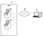
- the information processing system common to the embodiments includes a monitoring device 10, an automatic transaction device 20, and a dedicated network 22.
- the monitoring device 10 is an example of an information processing device in the present invention.
- the monitoring device 10 is a device that manages a failure occurrence state in the automatic transaction apparatus 20 by receiving failure occurrence information indicating the occurrence of a failure from the automatic transaction apparatus 20 described later.
- the monitoring apparatus 10 can communicate with the automatic transaction apparatus 20 via, for example, a dedicated network 22.
- the monitoring device 10 may be, for example, a PC (Personal Computer), a server, or a tablet terminal.
- the automatic transaction apparatus 20 is a customer operation type terminal that executes a cash deposit / withdrawal transaction based on an operation by a customer of a financial institution, for example.
- FIG. 1 shows an example in which the automatic transaction apparatus 20 is installed in a branch 2 of a financial institution, the present invention is not limited to this example.
- the automatic transaction apparatus 20 may be installed in a convenience store, a station, a hotel, a hospital, an amusement park, a restaurant, an office building, or the like.
- the automatic transaction apparatus 20 includes, for example, a control unit 200, a transaction execution unit 202, and a communication unit 204.
- the control unit 200 has a function of generally controlling the operation of the automatic transaction apparatus 20 using hardware such as a CPU (Central Processing Unit) and a RAM (Random Access Memory) built in the automatic transaction apparatus 20.
- the control unit 200 controls the operation of other components such as the communication unit 204.
- control unit 200 detects the occurrence of a failure in each part included in the transaction execution unit 202 described later. Furthermore, the control unit 200 generates failure occurrence information based on the detected content, and causes the communication device 204 to transmit the generated failure occurrence information to the monitoring device 10.
- the failure occurrence information includes, for example, the failure occurrence date and time, information on the part where the failure has occurred, and the content of the failure.
- the transaction execution unit 202 executes various transaction processes such as a deposit transaction and a withdrawal transaction according to the control of the control unit 200.
- the transaction execution unit 202 includes, for example, a cash system unit that performs cash deposit / withdrawal processing, a journal printer that performs print processing of statement slips, or a card mechanism unit that reads and writes data from a customer card. Including site.
- the communication unit 204 transmits / receives information to / from various apparatuses via the dedicated network 22, for example.
- the communication unit 204 transmits the generated failure occurrence information to the monitoring device 10 according to the control of the control unit 200.
- the dedicated network 22 is a network of a financial institution and is configured by, for example, an IP-VPN (Internet Protocol-Virtual Private Network).
- IP-VPN Internet Protocol-Virtual Private Network
- the automatic transaction apparatus 20 can communicate with the monitoring apparatus 10 via the dedicated network 22.
- the time limit until the failure is recovered when a failure occurs in the automatic transaction apparatus 20 is usually between the financial institution and the maintenance company of the automatic transaction apparatus 20.
- Each automatic transaction apparatus 20 is determined and contracted.
- the monitoring device 10 according to each embodiment has been created by focusing on the above circumstances.
- the monitoring device 10 according to each embodiment can output the failure information in an appropriate manner according to the recovery time limit and the elapsed time from the occurrence of the failure.
- each embodiment of the present invention will be described in detail.
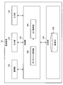
- FIG. 3 is a functional block diagram showing the configuration of the monitoring apparatus 10 according to the first embodiment.
- the monitoring device 10 includes a control unit 100, a communication unit 120, an output unit 122, an input unit 124, and a storage unit 126.
- the control unit 100 generally controls the operation of the monitoring device 10 using hardware such as a CPU 150 and a RAM 154 described later built in the monitoring device 10. As illustrated in FIG. 3, the control unit 100 includes a database management unit 102 and an output control unit 104.
- the database management unit 102 performs operations such as recording, updating, or deleting data with respect to a monitoring DB 128 described later. For example, when failure occurrence information is received from the automatic transaction apparatus 20, the database management unit 102 records the content of the received failure occurrence information in the monitoring DB 128 in association with the identification number of the automatic transaction apparatus 20.
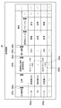
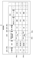
- the monitoring DB 128 is a database in which a failure occurrence state for each automatic transaction apparatus 20 is recorded.
- a configuration example of the monitoring DB 128 will be described with reference to FIG.
- an ATM number 1280, an address 1282, a recovery time limit 1284, a failure occurrence date 1286, and a part 1288 are recorded in association with each other.
- the ATM number 1280 records the identification number of the automatic transaction apparatus 20 installed in the financial institution.
- the address 1282 records the address of the facility where the corresponding automatic transaction apparatus 20 with the ATM number 1280 is installed.
- a recovery time limit predetermined for the corresponding automatic transaction apparatus 20 is recorded.
- the length of the recovery time limit is basically determined according to the area where the automatic transaction apparatus 20 is installed.
- the failure occurrence date / time 1286 the failure occurrence date / time indicated by the failure occurrence information received from the corresponding automatic transaction apparatus 20 is recorded.
- the part 1288 the failure status of each part included in the automatic transaction apparatus 20 is recorded based on the failure occurrence information received from the corresponding automatic transaction apparatus 20.
- the value recorded in the failure occurrence date 1286 is cleared, and each item included in the part 1288 The recorded value is updated (from “failure” to “normal”).
- the output control unit 104 causes the output unit 122 to output the failure information of the corresponding automatic transaction device 20, for example, on a display screen.
- the failure information includes, for example, an elapsed time from the failure occurrence date and time to the present.
- the failure information may include a difference between the recovery time limit recorded in the monitoring DB 128 in association with the corresponding automatic transaction apparatus 20 and the elapsed time from the failure occurrence date and time, that is, the remaining time until the recovery time limit.
- the failure information may further include various types of information recorded in the monitoring DB 128 in association with the corresponding automatic transaction apparatus 20.
- the output control unit 104 basically keeps displaying the failure information of the corresponding automatic transaction apparatus 20 until the failure of the corresponding automatic transaction apparatus 20 is recovered. That is, even if the person in charge has been dispatched to recover the failure of the corresponding automatic transaction apparatus 20, the failure information of the corresponding automatic transaction apparatus 20 continues to be displayed until the failure is recovered. This is because the purpose of displaying the failure information of the automatic transaction apparatus 20 is to enable monitoring on the screen whether or not the failure has been (completely) recovered in principle.
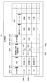
- the monitoring screen 30 is a screen that displays a failure occurrence status of each automatic transaction apparatus 20 recorded in the monitoring DB 128, for example. As shown in FIG. 5, the monitoring screen 30 displays, for each automatic transaction apparatus 20, for example, an ATM number 304a, a failure occurrence date / time 304b, and a remaining time 304c until the recovery time limit.
- the ATM number of the corresponding automatic transaction apparatus 20 is “101”, and the failure occurrence date is “October 1, 2014 13:00”. Elapsed time is “6 minutes”, the remaining time until the recovery time limit is “24 minutes”, and the part where the failure occurs is “cash unit” etc. .
- the output control unit 104 relates to the automatic transaction apparatus 20 in which a failure has occurred, based on the difference between the recovery time limit recorded in the monitoring DB 128 and the elapsed time from the failure occurrence date and time.
- the output mode of the 20 pieces of failure information is changed to the output unit 122.
- the output control unit 104 determines the difference between the recovery time limit recorded in the monitoring DB 128 and the elapsed time from the occurrence of the failure (that is, the recovery limit). It is possible to display the failure information of the automatic transaction apparatus 20 having a smaller remaining time until time on the display screen.
- the above functions will be described in more detail with reference to FIGS.
- the automatic transaction apparatus 20b with the ATM number “201” has a shorter remaining time until the recovery time limit than the automatic transaction apparatus 20a with the ATM number “101”. Therefore, as shown in FIG.
- the output control unit 104 displays the failure information 300b of the automatic transaction apparatus 20b above the failure information 300a of the automatic transaction apparatus 20a. It should be noted that the output control unit 104 displays the failure information of the automatic transaction apparatus 20 with a smaller remaining time until the recovery time limit only when the remaining time sort mode key 306c shown in FIG. 6 is selected by the person in charge. It is also possible to display the monitor screen 30 at a higher position.
- the output control unit 104 also determines that the difference between the recovery time limit recorded in the monitoring DB 128 and the elapsed time from the occurrence of the failure is smaller than a predetermined time, or the elapsed time exceeds the recovery time limit. In addition, it is possible to change the display character mode of the failure information of the automatic transaction apparatus 20 to the output unit 122.
- the predetermined time is “10 minutes”, in the example shown in FIG. 7, the remaining time (“9 minutes”) until the recovery time limit is the predetermined time for the automatic transaction apparatus 20b whose ATM number is “201”. Smaller than.
- the output control part 104 changes and displays the failure information 300b of the automatic transaction apparatus 20b, for example to a bold character.
- the output control unit 104 may change the character color such as changing the failure information 300b of the corresponding automatic transaction apparatus 20 from black to red, for example, or display the character information. May be displayed blinking. According to these display examples, the failure information of the automatic transaction apparatus 20 that is approaching the recovery time limit is displayed more emphasized on the monitoring screen 30, so that the person in charge can be alerted.
- the output control unit 104 determines that the difference between the recovery time limit recorded in the monitoring DB 128 and the elapsed time from the occurrence of the failure is smaller than a predetermined time, or the elapsed time exceeds the recovery time limit. In some cases, a warning pop-up message may be further displayed on the monitoring screen 30, or a warning sound may be further output.
- the communication unit 120 is an example of a receiving unit in the present invention.
- the communication unit 120 transmits and receives information to and from other devices via, for example, the LAN in the branch 2 or the dedicated network 22.
- the communication unit 120 receives failure occurrence information from the automatic transaction apparatus 20.
- the output unit 122 displays, for example, failure information of the automatic transaction apparatus 20 on a display screen or outputs a warning sound under the control of the output control unit 104.
- the input unit 124 receives various input operations on the monitoring device 10 by a person in charge. For example, the input unit 124 receives an operation for the user to select the sort mode key 306 of each item such as the sort mode key 306c for the remaining time on the monitoring screen 30 illustrated in FIG.
- the storage unit 126 can store various data such as the monitoring DB 128, for example.
- the configuration of the monitoring device 10 according to the first embodiment is not limited to the configuration described above.
- the monitoring DB 128 can be stored in another device that can communicate with the monitoring device 10.
- the output unit 122 or the input unit 124 may be included in another device that can communicate with the monitoring device 10 instead of being included in the monitoring device 10.
- the output unit 122 and the input unit 124 may be included together in one device, or each of the two devices. It may be included separately.
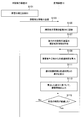
- control unit 200 generates failure occurrence information based on the content of the failure detected in S101. Then, the control unit 200 causes the generated failure occurrence information to be transmitted to the communication unit 204 to the monitoring device 10 (S103).
- the database management unit 102 of the monitoring device 10 records the content of the failure occurrence information received in S103 in the monitoring DB 128 in association with the corresponding automatic transaction device 20 (S105).
- the output control unit 104 acquires the recovery time limit recorded in association with the corresponding automatic transaction apparatus 20 from the monitoring DB 128 (S107).
- the output control unit 104 calculates the elapsed time from the failure occurrence date and time indicated by the failure occurrence information received in S103 to the present (S109).
- the output control unit 104 calculates a difference between the recovery time limit acquired in S107 and the elapsed time calculated in S109 (S111).
- the output control unit 104 converts the failure information including the content of the recovery time limit acquired in S107, the elapsed time calculated in S109, and the failure occurrence information received in S103 into the difference calculated in S111, for example.
- the output unit 122 outputs the data in a corresponding manner (S113).
- the output control unit 104 waits until a predetermined time such as 10 seconds elapses (S115). When the predetermined time has elapsed (S115: Yes), the output control unit 104 performs the operations after S109 again.
- the monitoring device 10 when failure occurrence information is received from the automatic transaction device 20, The failure information of the corresponding automatic transaction apparatus 20 is output to the output unit 122 in a manner corresponding to the difference between the recovery time limit associated with 20 and the elapsed time from the failure occurrence date and time indicated by the failure occurrence information. For this reason, since the failure information of the automatic transaction apparatus 20 is output in an appropriate manner according to the recovery time limit and the elapsed time from the occurrence of the failure, the person in charge can easily grasp the situation of the failure.
- the monitoring device 10 is an automatic transaction device in which the difference between the recovery time limit recorded in the monitoring DB 128 and the elapsed time since the failure occurrence is smaller. Twenty pieces of failure information are displayed on the upper part of the display screen. For this reason, the person in charge of the maintenance company can confirm at a glance the failure information of the automatic transaction apparatus 20 in which the remaining time until the recovery time limit is smaller. As a result, the person in charge can easily determine the automatic transaction apparatus 20 that should perform the recovery work preferentially from the plurality of automatic transaction apparatuses 20 in which the failure has occurred.
- the monitoring device 10 when the remaining time until the time limit for recovery is less than a predetermined time, the monitoring device 10 highlights the failure information of the corresponding automatic transaction device 20 on the display screen, or displays a warning. And output sound. Thereby, it is possible to alert the person in charge that the time limit for recovery is approaching.
- the maintenance company can reduce the risk of occurrence of a situation where the recovery time limit is exceeded before the failure is recovered. If the recovery time limit is exceeded, the maintenance company can quickly report the response status to the financial institution.
- Second Embodiment> The first embodiment has been described above. Next, a second embodiment will be described. As will be described later, according to the second embodiment, failure information of a plurality of automatic transaction apparatuses 20 in which a failure has occurred can be grouped for each recovery time limit and displayed on the display screen. is there.
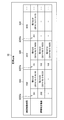
- FIG. 9 is a display example (monitoring screen 32) of failure information of the automatic transaction apparatus 20 according to the second embodiment.
- the output control unit 104 causes the monitoring screen 32 to display the failure information of the plurality of automatic transaction apparatuses 20 in which the failure has occurred for each recovery time limit.
- the output control unit 104 is an automatic transaction apparatus in which the remaining time until the recovery time limit is smaller in the individual recovery time limit display columns.
- the 20 pieces of failure information may be displayed on the upper side.
- the output control unit 104 may display the failure information of each automatic transaction apparatus 20 including the failure occurrence date and time (Note that FIG. 9 shows an example in which the failure occurrence date and time is displayed in parentheses. ing).
- the output control unit 104 displays the failure information of the corresponding automatic transaction apparatus 20 on the display screen in the area corresponding to the recovery time limit acquired in S107, and the difference calculated in S111. Display in a corresponding manner.
- the monitoring device 10 divides the failure information of the plurality of automatic transaction devices 20 in which the failure has occurred into groups for each recovery time limit. To display on the display screen.
- the length of the time limit for recovery is determined according to the area where the automatic transaction apparatus 20 is installed. For this reason, according to the second embodiment, failure information of a plurality of automatic transaction devices 20 in which a failure has occurred is displayed divided into groups of automatic transaction devices 20 that are installed in substantially the same region. Can do.
- the monitoring device 10 displays the failure information of the automatic transaction device 20 with the smaller remaining time until the recovery time limit in the display column of the individual recovery time limit, so that it is displayed higher. For this reason, since the information of the plurality of automatic transaction apparatuses 20 in which the failure has occurred is arranged and displayed by the two indexes of the recovery time limit and the remaining time until the recovery time limit, With reference to the two indexes, it is possible to more easily determine the automatic transaction apparatus 20 that should perform the restoration work with priority. For example, when the remaining time until the recovery time limit is the same, the person in charge can determine that the automatic transaction apparatus 20 having a longer recovery time limit should be prioritized for the recovery work.
- the monitoring device 10 includes a CPU 150, a ROM (Read Only Memory) 152, a RAM 154, an internal bus 156, an input / output interface 158, an input device 160, an output device 162, an HDD (Hard Disk Drive) 164, And a network interface 166.
- the CPU 150 functions as an arithmetic processing device and a control device, and controls the overall operation in the monitoring device 10 according to various programs. Further, the CPU 150 implements the function of the control unit 100 in the monitoring device 10.
- the CPU 150 is configured by a processor such as a microprocessor.
- the ROM 152 stores programs used by the CPU 150, calculation parameters, and the like.
- RAM154 temporarily stores programs used in the execution of the CPU 150, parameters that change as appropriate during the execution, and the like.
- the internal bus 156 is composed of a CPU bus and the like.
- the internal bus 156 connects the CPU 150, the ROM 152, and the RAM 154 to each other.
- the input / output interface 158 connects the input device 160, the output device 162, the HDD 164, and the network interface 166 to the internal bus 156.
- the HDD 164 exchanges data with the RAM 154 or the like via the input / output interface 158 and the internal bus 156.
- the input device 160 is, for example, an input means for a user to input information, such as a keyboard, mouse, touch panel, button, microphone, or switch, and an input control circuit that generates an input signal based on the input by the user and outputs the input signal to the CPU 150 Etc.
- the input device 160 functions as the input unit 124.
- the output device 162 functions as the output unit 122.
- This output device 162 includes, for example, a display device such as a liquid crystal display (LCD) device, an organic light emitting diode (OLED) device, or a lamp. This display device displays an image generated by the CPU 150 and the like.
- LCD liquid crystal display
- OLED organic light emitting diode
- the output device 162 includes an audio output device such as a speaker. This audio output device converts audio data or the like into audio and outputs it.
- the HDD 164 is a data storage device that functions as the storage unit 126.
- the HDD 164 includes, for example, a storage medium, a recording device that records data on the storage medium, a reading device that reads data from the storage medium, and a deletion device that deletes data recorded on the storage medium.
- the HDD 164 stores programs executed by the CPU 150 and various data.
- the network interface 166 is a communication interface composed of a communication device for connecting to a communication network such as the Internet, for example. This network interface 166 functions as the communication unit 120.
- the network interface 166 may be a wireless LAN compatible communication device, an LTE (Long Term Evolution) compatible communication device, or a wire communication device that performs wired communication.
- Modification 1> For example, when the failure occurrence information is received from the automatic transaction apparatus 20, the monitoring apparatus 10 outputs the failure information of the automatic transaction apparatus 20 based on the part where the failure has occurred in the automatic transaction apparatus 20. Can be changed to the output unit 122. As an example, in the example of the monitoring screen 30 shown in FIG. 5, the monitoring device 10 has a failure in the failure information of the automatic transaction apparatus 20a in which the portion where the failure has occurred is a “cash unit”. It may be displayed above the failure information of the automatic transaction apparatus 20b whose part is “journal printer”.
- the person in charge determines the automatic transaction apparatus 20 to be preferentially restored in consideration of the location of the failure occurring with respect to the plurality of automatic transaction apparatuses 20 in which the failure has occurred. can do.
- the monitoring apparatus 10 determines the failure information of the automatic transaction apparatus 20 based on the degree of influence of the failure in the automatic transaction apparatus 20. It is also possible to change the output mode to the output unit 122.
- the influence degree of the failure in the automatic transaction device 20 is, for example, that of the automatic transaction device 20 in which the failure occupies the total number of the automatic transaction devices 20 in the facility where the corresponding automatic transaction device 20 is installed. For example, the ratio of the number of units and the number of users of the automatic transaction apparatus 20 in a predetermined period such as “average number of users per day”.
- the monitoring apparatus 10 displays the display screen.
- failure information of the corresponding automatic transaction apparatus 20 may be displayed further upward.
- the person in charge determines the automatic transaction apparatus 20 to be preferentially restored in consideration of the degree of influence of the failure occurring with respect to the plurality of automatic transaction apparatuses 20 in which the failure has occurred. Judgment can be made.
- the monitoring device 10 when the failure occurrence information is received from the automatic transaction device 20, the monitoring device 10 outputs the failure information of the automatic transaction device 20 based on the degree of failure in the automatic transaction device 20. It is also possible to change the mode of the output to the output unit 122. For example, normally, regarding a jam failure, a different number (jam number) is preset for each type of failure. For this reason, when a jam failure occurs, the monitoring device 10 causes the failure of the corresponding automatic transaction device 20 on the display screen as the degree of failure associated with the jam number indicated by the failure occurrence information increases. Information may be displayed further upward.
Landscapes
- Business, Economics & Management (AREA)
- Engineering & Computer Science (AREA)
- Accounting & Taxation (AREA)
- Finance (AREA)
- Physics & Mathematics (AREA)
- Theoretical Computer Science (AREA)
- General Physics & Mathematics (AREA)
- General Business, Economics & Management (AREA)
- Strategic Management (AREA)
- Economics (AREA)
- Marketing (AREA)
- Tourism & Hospitality (AREA)
- Primary Health Care (AREA)
- General Health & Medical Sciences (AREA)
- Human Resources & Organizations (AREA)
- Health & Medical Sciences (AREA)
- Development Economics (AREA)
- Technology Law (AREA)
- Financial Or Insurance-Related Operations Such As Payment And Settlement (AREA)
- Management, Administration, Business Operations System, And Electronic Commerce (AREA)
Abstract
Le problème décrit par la présente invention est de fournir un dispositif de traitement d'informations grâce auquel, lorsque des informations de défaillance sont sorties, l'état de la défaillance peut être compris plus facilement par un utilisateur. La solution selon l'invention porte sur un dispositif de traitement d'informations qui est pourvu : d'une unité de réception qui reçoit des informations d'occurrence de défaillance indiquant qu'une défaillance s'est produite dans un dispositif de transaction automatisée ; et d'une unité de commande de sortie qui amène une unité de sortie à changer la forme dans laquelle des informations indiquant la défaillance du dispositif de transaction automatisée sont sorties, sur la base de la différence entre une limite de temps de récupération associée au dispositif de transaction automatisée indiquée dans les informations d'occurrence de défaillance reçues, et le temps écoulé depuis la date et l'heure auxquelles la défaillance s'est produite, indiqué dans les informations d'occurrence de défaillance.
Applications Claiming Priority (2)
| Application Number | Priority Date | Filing Date | Title |
|---|---|---|---|
| JP2014232707A JP6447040B2 (ja) | 2014-11-17 | 2014-11-17 | 情報処理装置 |
| JP2014-232707 | 2014-11-17 |
Publications (1)
| Publication Number | Publication Date |
|---|---|
| WO2016080098A1 true WO2016080098A1 (fr) | 2016-05-26 |
Family
ID=56013656
Family Applications (1)
| Application Number | Title | Priority Date | Filing Date |
|---|---|---|---|
| PCT/JP2015/078356 Ceased WO2016080098A1 (fr) | 2014-11-17 | 2015-10-06 | Dispositif de traitement d'informations |
Country Status (2)
| Country | Link |
|---|---|
| JP (1) | JP6447040B2 (fr) |
| WO (1) | WO2016080098A1 (fr) |
Families Citing this family (1)
| Publication number | Priority date | Publication date | Assignee | Title |
|---|---|---|---|---|
| JP2023180051A (ja) * | 2022-06-08 | 2023-12-20 | グローリー株式会社 | 遠隔対応システムおよび処理装置 |
Citations (5)
| Publication number | Priority date | Publication date | Assignee | Title |
|---|---|---|---|---|
| JP2007034353A (ja) * | 2005-07-22 | 2007-02-08 | Mitsubishi Electric Corp | 業務管理装置、業務管理方法および業務管理プログラム |
| JP2009181537A (ja) * | 2008-02-01 | 2009-08-13 | Hitachi Information Systems Ltd | インシデント管理システム及び同管理方法並びに同管理プログラム |
| JP2012155505A (ja) * | 2011-01-26 | 2012-08-16 | Nippon Atm Kk | 自動取引装置 |
| JP2012256143A (ja) * | 2011-06-08 | 2012-12-27 | Hitachi Systems Ltd | 保守管理システム、作業優先順位算出方法およびプログラム |
| JP2014026533A (ja) * | 2012-07-27 | 2014-02-06 | Oki Electric Ind Co Ltd | 取引システム、取引装置及び情報処理プログラム |
Family Cites Families (1)
| Publication number | Priority date | Publication date | Assignee | Title |
|---|---|---|---|---|
| JP5121381B2 (ja) * | 2007-10-11 | 2013-01-16 | 株式会社日立システムズ | 保守・管理サービス支援システムにおける品質評価システム |
-
2014
- 2014-11-17 JP JP2014232707A patent/JP6447040B2/ja active Active
-
2015
- 2015-10-06 WO PCT/JP2015/078356 patent/WO2016080098A1/fr not_active Ceased
Patent Citations (5)
| Publication number | Priority date | Publication date | Assignee | Title |
|---|---|---|---|---|
| JP2007034353A (ja) * | 2005-07-22 | 2007-02-08 | Mitsubishi Electric Corp | 業務管理装置、業務管理方法および業務管理プログラム |
| JP2009181537A (ja) * | 2008-02-01 | 2009-08-13 | Hitachi Information Systems Ltd | インシデント管理システム及び同管理方法並びに同管理プログラム |
| JP2012155505A (ja) * | 2011-01-26 | 2012-08-16 | Nippon Atm Kk | 自動取引装置 |
| JP2012256143A (ja) * | 2011-06-08 | 2012-12-27 | Hitachi Systems Ltd | 保守管理システム、作業優先順位算出方法およびプログラム |
| JP2014026533A (ja) * | 2012-07-27 | 2014-02-06 | Oki Electric Ind Co Ltd | 取引システム、取引装置及び情報処理プログラム |
Also Published As
| Publication number | Publication date |
|---|---|
| JP2016095772A (ja) | 2016-05-26 |
| JP6447040B2 (ja) | 2019-01-09 |
Similar Documents
| Publication | Publication Date | Title |
|---|---|---|
| US11461721B2 (en) | Method and system for managing a technical installation | |
| TW201019104A (en) | System and method for detecting behavior anomaly in information access | |
| JP6291908B2 (ja) | 金銭処理装置用の操作ガイダンス表示システム、プログラムおよび記録媒体 | |
| WO2014117245A1 (fr) | Prévision de défaillances et de problèmes de performances | |
| US20100153597A1 (en) | Generating Furtive Glance Cohorts from Video Data | |
| US20120231427A1 (en) | Job procedure display apparatus, method of controlling job procedure display apparatus and non-transitory, computer readable storage medium | |
| EP3177991A1 (fr) | Réalisation d'une procédure d'utilisation normalisée associée à un système de surveillance d'une installation | |
| JP7463076B2 (ja) | 情報表示システムおよび情報表示方法 | |
| JP5752882B2 (ja) | 監視カメラシステム | |
| US12147451B1 (en) | Aggregated application data store | |
| JP6447040B2 (ja) | 情報処理装置 | |
| JP7517416B2 (ja) | 画像処理装置、画像処理方法、及びプログラム | |
| JP2017156863A (ja) | 監視システム、プログラム | |
| US8572503B2 (en) | Device for analysing variable magnitudes by simultaneous multiple windowing | |
| JP2009116812A (ja) | 不正利用検出装置及びそのプログラム | |
| JP7849476B2 (ja) | 監視装置及び監視装置方法 | |
| JP2019191662A (ja) | 設備遠隔監視システムおよび設備遠隔監視方法 | |
| KR102412873B1 (ko) | 자산의 보안 감시 내역을 시간에 따라 시각적으로 표시하는 자산 운영 장치, 방법 및 프로그램 | |
| JP5551945B2 (ja) | 自動取引装置、不良判定方法及び不良判定プログラム | |
| CN105608788B (zh) | 监视装置及监视系统 | |
| Jie et al. | Apple Versus Samsung patent lawsuit: An issue and crisis management approach | |
| JP6872120B2 (ja) | 情報処理装置及び情報処理プログラム | |
| US9741185B2 (en) | Anti-pass back capacity predictive system and method for access control host processing system | |
| JP6720560B2 (ja) | 情報処理装置 | |
| KR101641651B1 (ko) | 비디오 감시 시스템 및 그 제어 방법 |
Legal Events
| Date | Code | Title | Description |
|---|---|---|---|
| 121 | Ep: the epo has been informed by wipo that ep was designated in this application |
Ref document number: 15860557 Country of ref document: EP Kind code of ref document: A1 |
|
| NENP | Non-entry into the national phase |
Ref country code: DE |
|
| 122 | Ep: pct application non-entry in european phase |
Ref document number: 15860557 Country of ref document: EP Kind code of ref document: A1 |