WO2016075937A1 - Procédé de fabrication et dispositif de fabrication d'un article moulé par compression - Google Patents
Procédé de fabrication et dispositif de fabrication d'un article moulé par compression Download PDFInfo
- Publication number
- WO2016075937A1 WO2016075937A1 PCT/JP2015/005632 JP2015005632W WO2016075937A1 WO 2016075937 A1 WO2016075937 A1 WO 2016075937A1 JP 2015005632 W JP2015005632 W JP 2015005632W WO 2016075937 A1 WO2016075937 A1 WO 2016075937A1
- Authority
- WO
- WIPO (PCT)
- Prior art keywords
- region
- press
- punch
- vertical wall
- ridge line
- Prior art date
Links
Images


Classifications
-
- B—PERFORMING OPERATIONS; TRANSPORTING
- B21—MECHANICAL METAL-WORKING WITHOUT ESSENTIALLY REMOVING MATERIAL; PUNCHING METAL
- B21D—WORKING OR PROCESSING OF SHEET METAL OR METAL TUBES, RODS OR PROFILES WITHOUT ESSENTIALLY REMOVING MATERIAL; PUNCHING METAL
- B21D22/00—Shaping without cutting, by stamping, spinning, or deep-drawing
- B21D22/02—Stamping using rigid devices or tools
- B21D22/06—Stamping using rigid devices or tools having relatively-movable die parts
-
- B—PERFORMING OPERATIONS; TRANSPORTING
- B21—MECHANICAL METAL-WORKING WITHOUT ESSENTIALLY REMOVING MATERIAL; PUNCHING METAL
- B21D—WORKING OR PROCESSING OF SHEET METAL OR METAL TUBES, RODS OR PROFILES WITHOUT ESSENTIALLY REMOVING MATERIAL; PUNCHING METAL
- B21D19/00—Flanging or other edge treatment, e.g. of tubes
-
- B—PERFORMING OPERATIONS; TRANSPORTING
- B21—MECHANICAL METAL-WORKING WITHOUT ESSENTIALLY REMOVING MATERIAL; PUNCHING METAL
- B21D—WORKING OR PROCESSING OF SHEET METAL OR METAL TUBES, RODS OR PROFILES WITHOUT ESSENTIALLY REMOVING MATERIAL; PUNCHING METAL
- B21D22/00—Shaping without cutting, by stamping, spinning, or deep-drawing
- B21D22/20—Deep-drawing
- B21D22/26—Deep-drawing for making peculiarly, e.g. irregularly, shaped articles
-
- B—PERFORMING OPERATIONS; TRANSPORTING
- B21—MECHANICAL METAL-WORKING WITHOUT ESSENTIALLY REMOVING MATERIAL; PUNCHING METAL
- B21D—WORKING OR PROCESSING OF SHEET METAL OR METAL TUBES, RODS OR PROFILES WITHOUT ESSENTIALLY REMOVING MATERIAL; PUNCHING METAL
- B21D24/00—Special deep-drawing arrangements in, or in connection with, presses
- B21D24/04—Blank holders; Mounting means therefor
-
- B—PERFORMING OPERATIONS; TRANSPORTING
- B21—MECHANICAL METAL-WORKING WITHOUT ESSENTIALLY REMOVING MATERIAL; PUNCHING METAL
- B21D—WORKING OR PROCESSING OF SHEET METAL OR METAL TUBES, RODS OR PROFILES WITHOUT ESSENTIALLY REMOVING MATERIAL; PUNCHING METAL
- B21D47/00—Making rigid structural elements or units, e.g. honeycomb structures
-
- B—PERFORMING OPERATIONS; TRANSPORTING
- B21—MECHANICAL METAL-WORKING WITHOUT ESSENTIALLY REMOVING MATERIAL; PUNCHING METAL
- B21D—WORKING OR PROCESSING OF SHEET METAL OR METAL TUBES, RODS OR PROFILES WITHOUT ESSENTIALLY REMOVING MATERIAL; PUNCHING METAL
- B21D5/00—Bending sheet metal along straight lines, e.g. to form simple curves
- B21D5/01—Bending sheet metal along straight lines, e.g. to form simple curves between rams and anvils or abutments
Definitions
- the present invention relates to a method and an apparatus for manufacturing a press-molded product used for automobiles, various vehicles other than automobiles, home appliances, ships, building materials and the like.
- the body of an automobile includes various structural members (eg, floor cross members, side sills, side members, etc.).
- a press-formed product made of a metal plate such as a steel plate is often used.
- a press-formed product is obtained by subjecting a metal plate to press working by bending because of material breakage at the time of press forming, shape freezing property, and superiority in manufacturing cost.
- the press-formed product has, for example, a groove shape or a hat-shaped cross-sectional shape.
- the press-formed product having a groove-shaped cross section includes a top plate portion and a pair of vertical wall portions extending from the top plate portion.
- the press-formed product having a hat-shaped cross section further includes a pair of flange portions extending from each vertical wall portion.
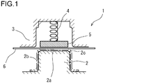
- FIG. 1 is an explanatory view schematically showing a configuration example of a press forming apparatus that performs general bending forming.
- the press molding apparatus 1 is an apparatus for manufacturing a press-formed product having a groove-shaped cross section or a hat-shaped cross section.
- FIG. 1 exemplifies a case of manufacturing a press-formed product having a hat-shaped cross section (refer to a one-dot chain line in the drawing).
- the press molding apparatus 1 includes a punch 2 as a lower mold and a die 3 and a pad 5 that are paired with the punch 2 as an upper mold.
- the pad 5 is supported via the pressing member 4 on the die 3 or an upper mold holder or slide that operates integrally with the die 3.
- the pad 5 can be accommodated in the die 3 and constitutes a part of the die 3 while being accommodated in the die 3.
- Bending molding in which the metal plate 6 is molded into a press-molded product by such a press molding apparatus 1 is performed as follows. Prior to forming, the metal plate 6 is sandwiched between the punch 2 and the pad 5. That is, before the punch 2 starts to push the metal plate 6 into the die 3, the portion of the metal plate 6 that is formed on the top plate portion of the press-formed product is restrained by the punch 2 and the pad 5. In this state, the die 3 is lowered to the bottom dead center. Thereby, the top plate portion of the press-formed product is formed along the upper surface (tip surface) 2 a of the punch 2. The vertical wall portion is formed along the side surface 2 b of the punch 2. A ridge line portion is formed between the top plate portion and the vertical wall portion. A ridge line portion connecting the top plate portion and the vertical wall portion is formed along the punch shoulder portion 2 c of the punch 2.
- pad bending such referred to as pad bending.
- a high-strength steel plate having a tensile strength of 440 MPa or more is used as the metal plate 6 that is a material of the structural member.
- a 590 MPa class high strength steel sheet may be used, and in some cases, a 980 MPa class high strength steel sheet, and further a 1180 MPa class high strength steel sheet are used.
- the shape of the structural member may be relatively complicated. This is due to design restrictions such as prevention of interference between the structural member and other members, joining of the structural member and other members, and securing of a desired space.
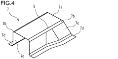
- FIGS. 2 to 8 are perspective views showing an example of a press-formed product having a relatively complicated shape.
- FIG. 2 shows a first example formed from a high-strength steel plate (alloyed hot-dip galvanized steel plate having a thickness of 1.2 mm made of DP (Dual-Phase) steel) having a tensile strength of 590 MPa or more.
- the press-formed product 7 is shown.
- FIGS. 3 to 8 show second to seventh examples formed from high-strength steel sheets having a tensile strength of 440 MPa or more (alloyed hot-dip galvanized steel sheets, non-plated steel sheets and the like having a thickness of about 1.2 mm), respectively.
- the press-formed product 7 is shown.
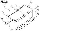
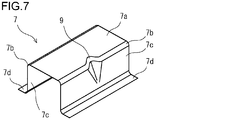
- any press-formed product 7 in the first to seventh examples are all hat-shaped. That is, any press-formed product 7 includes a top plate portion 7a, a vertical wall portion 7c extending from the left and right ends of the top plate portion 7a, and a ridge line portion 7b between the top plate portion 7a and the vertical wall portion 7c. And a flange portion 7d extending from the lower end of each vertical wall portion 7c. Further, the press-formed product 7 has a shape changing portion 9 in a part of the ridge line portion 7b.
- the shape changing portions 9 are provided on both the ridge line portions 7b at both ends of the top plate portion 7a. These shape changing portions 9 are portions in which the height of the ridge line portion 7 b changes at a location approximately in the center in the longitudinal direction of the press-formed product 7. In this case, a stepped portion 8 is formed on the top plate portion 7a in a region connecting the shape changing portions 9 to each other.
- the shape changing portions 9 are provided on both the ridge line portions 7b at both ends of the top plate portion 7a.
- These shape changing portions 9 are those in which the height of the ridge line portion 7 b changes in a wide range substantially at the center in the longitudinal direction of the press-formed product 7. In this case, the height of the top plate portion 7a changes gently corresponding to the position of the shape changing portion 9.
- the shape changing portion 9 is provided on one of the ridge line portions 7b at both ends of the top plate portion 7a.
- the shape changing portion 9 is a portion in which the arc length in the cross section of the ridge line portion 7b changes at a location approximately at the center in the longitudinal direction of the press-formed product 7. In this case, the angle formed by the top plate portion 7a and the vertical wall portion 7c changes corresponding to the position of the shape changing portion 9.
- the shape changing portions 9 are provided on both the ridge line portions 7b at both ends of the top plate portion 7a.
- These shape change parts 9 are those in which the ridge line part 7 b is twisted in a wide range substantially at the center in the longitudinal direction of the press-formed product 7. In this case, the top plate portion 7a and the vertical wall portion 7c are twisted corresponding to the position of the shape changing portion 9.
- the shape changing portions 9 are provided on both the ridge line portions 7b at both ends of the top plate portion 7a. These shape changing portions 9 are a wide area in the center of the press-formed product 7 in the longitudinal direction, and the ridge line portion 7 b is bent in the width direction of the press-formed product 7. In this case, the top plate portion 7 a and the vertical wall portion 7 c are bent in the width direction of the press-formed product 7 in correspondence with the position of the shape changing portion 9.
- the shape changing portion 9 is provided on one of the ridge line portions 7b at both ends of the top plate portion 7a.
- the shape changing portion 9 is a portion approximately in the center in the longitudinal direction of the press-formed product 7, and the ridge line portion 7 b is recessed in the width direction of the press-formed product 7.
- the top plate portion 7 a and the vertical wall portion 7 c are recessed in the width direction of the press-formed product 7, corresponding to the position of the shape changing portion 9.
- the shape changing portion 9 is provided on one of the ridge line portions 7b at both ends of the top plate portion 7a.
- the shape changing portion 9 is a portion in which the radius of curvature in the cross section of the ridge line portion changes in a range from the substantially center in the longitudinal direction of the press-formed product 7 to one end.
- the width of the top plate portion 7a and the height of the vertical wall portion 7c change corresponding to the position of the shape changing portion 9.
- Patent Document 1 Japanese Patent Application Laid-Open No. 2010-115674
- Patent Document 2 Japanese Patent Application Laid-Open No. 2012-024837
- Patent Document 1 discloses a technique for imparting an uneven bead to a vertical wall portion and a flange portion. By providing the bead, the difference in line length generated at the end of the material before and after bending is reduced. Thereby, generation
- Patent Document 2 discloses a technique for suppressing wrinkles generated in a vertical wall portion on the outer side of a bent portion in a press-formed product, which is intended for manufacturing a press-formed product having a hat-shaped cross section and bent in the width direction.
- a surplus portion is provided only on the outside of the bent portion.
- the surplus portion is bent in the direction opposite to the pressing direction by upper and lower molds and is sandwiched between the molds. Thereby, tension is given to the outside of the bent portion, and the generation of wrinkles is suppressed.
- Patent Document 2 The technique disclosed in Patent Document 2 is not applicable to the manufacture of all the press-formed products 7 of the first to seventh examples. Moreover, according to the technique, since there is a surplus part, a decrease in yield is inevitable.
- the object of the present invention is to change the shape even when a high-strength steel sheet is used as a material, for example, when a press-formed product having a groove-shaped cross section or a hat-shaped cross section having a shape change portion at a part of the ridge line portion is used. It is to provide a method of manufacturing a press-molded product and a manufacturing apparatus thereof that can reduce the generation of wrinkles in the region of the portion and the region in the vicinity thereof.
- a manufacturing method is a method for manufacturing a press-formed product from a material.
- the press-molded product includes a top plate portion, a vertical wall portion extending from each end of the top plate portion, and a ridge line portion between the vertical wall portion and the top plate portion, A part has a shape change part.
- the manufacturing method includes: A preparation step of preparing a metal plate as the material; And a pressing process for pressing the material using a punch and a pad and die paired with the punch.
- the pressing process includes By the punch and the pad, at least a region adjacent to the shape change portion in the region of the top plate portion, a region of at least the shape change portion in the region of each ridge line portion, and the vertical wall portion A first step of forming a region at least from the boundary between the vertical wall portion and the ridge line portion to a predetermined height in the region adjacent to at least the shape changing portion; Subsequent to the first step, a second step of forming the remaining region with the punch and the die while the material is sandwiched between the punch and the pad.
- the predetermined height is 2 mm or more from the boundary between the vertical wall portion and the ridge line portion and half or less of the total height of the vertical wall portion.
- the following configuration can be adopted for the manufacturing method (1).
- the first step the vertical wall portion and the ridge line portion among the entire region of the top plate portion, the entire region of each ridge line portion, and the region of each vertical wall portion by the punch and the pad.
- a region from the boundary to the predetermined height is formed.
- an area exceeding the predetermined height is formed in the area of each vertical wall portion by the punch and the die.
- the shape changing portion of the ridge line portion is at least one of the following (a) to (f).
- a manufacturing apparatus is an apparatus for manufacturing a press-formed product from a material.
- the press-molded product includes a top plate portion, a vertical wall portion extending from each end of the top plate portion, and a ridge line portion between the vertical wall portion and the top plate portion, A part has a shape change part.
- the manufacturing apparatus includes a punch and a pad and die that are paired with the punch.
- the punch has a front end surface corresponding to the region of the top plate portion, a side surface corresponding to the region of the vertical wall portions, and a punch shoulder portion corresponding to the region of the ridge line portions.
- the pad has a bottom surface corresponding to at least a region adjacent to the shape changing portion in the region of the top plate portion, a corner corresponding to at least the region of the shape changing portion in the region of each ridge line portion, and It has an inner surface corresponding to a region from the boundary between the vertical wall portion and the ridge line portion to a predetermined height, which is at least a region adjacent to the shape changing portion among the regions of the vertical wall portions.
- An apparatus for manufacturing a press-formed product includes a punch, a pad, and a die.
- the punch includes a front end surface, a side surface, and a punch shoulder provided between the front end surface and the side surface.
- the punch shoulder is provided with a shape changing portion in a part of the punch in the longitudinal direction.
- the pad includes a bottom surface facing the tip surface of the punch, an inner surface facing a part of the side surface of the punch, and a corner facing the punch shoulder provided between the bottom surface and the inner surface.
- the die includes an inner side surface facing a region excluding a region facing the inner side surface of the pad in the side surface region of the punch.
- the predetermined height is 2 mm or more from the boundary between the vertical wall portion and the ridge line portion, and is half or less of the total height of the vertical wall portion.
- the manufacturing apparatus of the above (2) can adopt the following configuration.
- the bottom surface of the pad corresponds to the entire area of the top plate portion.
- Each corner of the pad corresponds to the entire area of each ridge line.
- Each inner side surface of the pad corresponds to a region from a boundary between the vertical wall portion and the ridge line portion to the predetermined height among the regions of the vertical wall portions.
- the die has an inner surface corresponding to a region exceeding the predetermined height among the regions of the vertical wall portions.
- the die is divided corresponding to the vertical wall portions.
- the manufacturing apparatus includes a die moving mechanism that moves the dies toward the side surfaces of the punch after the material has been pushed into the pad by the punch.
- the shape change The generation of wrinkles can be reduced in the region of the portion and the region in the vicinity thereof.
- FIG. 1 is a cross-sectional view schematically showing a configuration example of a press forming apparatus that performs general bending forming.
- FIG. 2 is a perspective view showing an example of a press-formed product having a relatively complicated shape.
- FIG. 3 is a perspective view showing an example of a press-formed product having a relatively complicated shape.
- FIG. 4 is a perspective view showing an example of a press-formed product having a relatively complicated shape.
- FIG. 5 is a perspective view showing an example of a press-formed product having a relatively complicated shape.
- FIG. 6 is a perspective view showing an example of a press-formed product having a relatively complicated shape.
- FIG. 7 is a perspective view showing an example of a press-formed product having a relatively complicated shape.
- FIG. 1 is a cross-sectional view schematically showing a configuration example of a press forming apparatus that performs general bending forming.
- FIG. 2 is a perspective view showing an example of a press-formed product having
- FIG. 8 is a perspective view showing an example of a press-formed product having a relatively complicated shape.
- FIG. 9 is a perspective view showing an example of the configuration of a manufacturing apparatus used for manufacturing a press-formed product according to the first embodiment of the present invention.
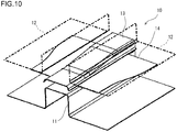
- FIG. 10 is a perspective view showing an example of the configuration of a manufacturing apparatus used for manufacturing a press-formed product according to the first embodiment of the present invention.
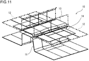
- FIG. 11 is a perspective view showing an example of the configuration of a manufacturing apparatus used for manufacturing a press-formed product according to the first embodiment of the present invention.
- FIG. 12A is a diagram illustrating a state of a press working process performed by the manufacturing apparatus according to the first embodiment, and illustrates a state before the start of molding.
- FIG. 12A is a diagram illustrating a state of a press working process performed by the manufacturing apparatus according to the first embodiment, and illustrates a state before the start of molding.
- FIG. 12B is a diagram illustrating a state of the press working process by the manufacturing apparatus according to the first embodiment, and illustrates a state in the initial stage of molding.
- FIG. 12C is a diagram showing a state of the press working process by the manufacturing apparatus of the first embodiment, and shows a state at the time of completion of molding.
- FIG. 13A is a diagram illustrating a state of a press working process performed by the manufacturing apparatus according to the second embodiment, and illustrates a state before the start of molding.
- FIG. 13B is a diagram illustrating a state of the press working process by the manufacturing apparatus according to the second embodiment, and illustrates a state in the initial stage of molding.
- FIG. 13C is a diagram illustrating a state of the press working process performed by the manufacturing apparatus according to the second embodiment, and illustrates a state when the molding is completed.
- FIG. 14A is a diagram illustrating a state of a press working process performed by the manufacturing apparatus according to the third embodiment, and illustrates a state before the start of molding.
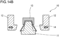
- FIG. 14B is a diagram illustrating a state of the press working process by the manufacturing apparatus according to the third embodiment, and illustrates a state in the initial stage of molding.
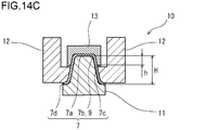
- FIG. 14C is a diagram showing the state of the press working process by the manufacturing apparatus of the third embodiment, and shows a state at the time of completion of molding.
- FIG. 15 is a diagram showing the results of investigation in the example.
- the present inventors obtained the following knowledge as a result of intensive studies to solve the above problems.
- the generation of wrinkles can be reduced by suppressing an excessive surplus in the region of the shape change portion and the region in the vicinity thereof.
- an area restricted from the initial stage of press working by the punch and the pad (hereinafter also referred to as “restrained area”) may be enlarged.
- the restriction region is not only the region of the top plate portion, but also the region of the shape change portion where wrinkles are likely to occur, and a partial region of the vertical wall portion adjacent to the shape change portion.
- FIGS. 9 to 11 are perspective views showing an example of the configuration of a manufacturing apparatus used for manufacturing a press-formed product in the first embodiment of the present invention.
- Each of the manufacturing apparatuses 10 shown in FIGS. 9 to 11 is a press molding apparatus.
- the press molding apparatus 10 shown in FIG. 9 is an apparatus for manufacturing the first example of the press molded product 7 having the hat-shaped cross section shown in FIG.
- a press molding apparatus 10 shown in FIG. 10 is an apparatus for manufacturing the press-formed product 7 of the second example having the hat-shaped cross section shown in FIG.
- a press molding apparatus 10 shown in FIG. 11 is an apparatus for manufacturing the press molded product 7 of the sixth example having the hat-shaped cross section shown in FIG.
- FIG. 12A to 12C are views showing the state of the press working process by the manufacturing apparatus of the first embodiment.
- FIG. 12A shows a state before the start of molding.
- FIG. 12B shows an initial state of molding.
- FIG. 12C shows a state when the molding is completed.
- These drawings show a cross section of the region of the shape changing portion.
- the press molding apparatus 10 includes a punch 11 as a lower mold and a die 12 and a pad 13 as an upper mold. That is, the punch 11, the die 12 and the pad 13 are paired.
- the die 12 is indicated by a one-dot chain line in FIGS.
- the punch 11 includes an upper surface 11a (tip surface), a pair of side surfaces 11b, and a punch shoulder portion 11c provided between the upper surface 11a and the side surface 11b.
- the punch shoulder 11c is a part connecting the upper surface 11a and the side surface 11b.
- the shape of the upper surface 11 a is a shape corresponding to the region of the top plate portion 7 a of the press-formed product 7.
- the shape of the side surface 11 b is a shape corresponding to the region of the vertical wall portion 7 c of the press-formed product 7.
- the shape of the punch shoulder portion 11 c is a shape corresponding to the region of the ridge line portion 7 b (including the shape changing portion 9) of the press-formed product 7.
- the punch shoulder portion 11 c is provided with a shape changing portion in part in the longitudinal direction of the punch 11.
- the shape of the shape changing portion of the punch shoulder portion 11 c is a shape corresponding to the region of the shape changing portion 9 existing in a part of the ridge line portion 7 b of the press-formed product 7. That is, the punch shoulder portion 11c includes a portion where the cross-sectional shape changes in the longitudinal direction of the punch 11 or the extending direction of the punch shoulder portion 11c is bent.
- the pad 13 is disposed to face the upper surface 11a of the punch 11.
- the pad 13 includes a bottom surface 13a, a pair of inner side surfaces 13b, and a corner portion 13c.
- the corner 13c is a part connecting the bottom surface 13a and the inner side surface 13b.
- the shape of the bottom surface 13 a is a shape corresponding to the region of the top plate portion 7 a of the press-formed product 7. That is, the bottom surface 13 a faces the top surface 11 a of the punch 11, and the shape thereof is a shape that matches the shape of the top surface 11 a of the punch 11.
- the shape of the corner portion 13 c is a shape corresponding to the region of the ridge line portion 7 b (including the shape changing portion 9) of the press-formed product 7.
- the corner 13c faces the punch shoulder 11c, and the shape thereof is a shape that matches the shape of the punch shoulder 11c.
- the “combined shape” here means a shape in which the unevenness of the opposite portions across the material metal plate is reversed.
- the inner side surface 13 b faces a part of the side surface 11 b of the punch 11.
- the shape of the inner side surface 13b is a shape corresponding to the region from the boundary between the vertical wall portion 7c and the ridge line portion 7b to the predetermined height h in the region of the vertical wall portion 7c of the press-formed product 7. Yes (see FIG. 12C).
- the pad 13 is supported by an upper mold holder that operates integrally with the slide via a pressure member.
- the pressurizing member is a hydraulic cylinder, a gas cylinder, a spring, rubber or the like, and applies a downward force (force toward the punch 11) to the pad 13.
- the pad 13 may be supported by a slide that operates integrally with the upper mold holder as long as the pad 13 is supported via a pressure member.
- the die 12 is divided into two, and each die 12 is arranged outside the both sides of the pad 13, respectively.
- Each die 12 includes an inner surface 12a.
- the shape of the inner surface 12a is a shape corresponding to the region exceeding the predetermined height h in the region of the vertical wall portion 7c of the press-formed product 7. That is, the inner side surface 12 a faces the region excluding the region facing the inner side surface 13 b of the pad 13 in the region of the side surface 11 b of the punch 11.
- Each die 12 is connected to an upper mold holder or a slide via a die moving mechanism such as a cam.
- each die 12 is slanted toward each side surface 11b of the punch 11. Move downward (see white arrow in FIG. 12B).
- the manufacturing method of the press-formed product 7 using the press forming apparatus 10 of the first embodiment includes the following preparation process and press working process.
- a metal plate 14 is prepared as a material.
- the metal plate 14 for example, a high strength steel plate having a tensile strength of 440 MPa or more can be used.
- the metal plate 14 may be a 590 MPa class high strength steel plate, a 980 MPa class high strength steel plate, or a 1180 MPa class high strength steel plate.
- a stainless steel plate, an aluminum plate, a copper plate, or the like can be used as the metal plate 14.
- the press forming apparatus 10 is used to press the metal plate 14 by bending to produce the press-formed product 7.
- the situation in the press working process will be specifically described below.
- the slide is further lowered, the pressing of the punch 11 into the pad 13 reaches the bottom dead center, and the processing by the punch 11 and the pad 13 is completed.
- the whole region of the top-plate part 7a is shape
- the entire region of the ridge line portion 7b including the shape changing portion 9 is formed.
- region to predetermined height h is shape
- each die 12 is moved obliquely downward toward each side surface 11b of the punch 11 so as to be narrowed by the die moving mechanism (see the white arrow in FIG. 12B).
- the processing by the punch 11 and the die 12 is started, and a region exceeding the predetermined height h is formed among the regions of the vertical wall portions 7c (see FIG. 12C). That is, the remaining area is formed by the punch 11 and the die 12.
- the flange portion 7d connected to the vertical wall portion 7c is also formed by the punch 11 and the die 12. In this way, a press-formed product 7 is obtained.
- the region of the shape changing portion 9 where wrinkles are likely to occur and the portion of the vertical wall portion 7 c adjacent to the shape changing portion 9 are formed in the punch 11. And the pad 13 are restrained from the initial stage of processing. For this reason, there is no room for a surplus in the region of the shape change portion 9 and the region in the vicinity thereof during press working. As a result, even when a high-strength steel plate is used as a raw material, the generation of wrinkles can be reduced in the region of the shape changing portion 9 and the region in the vicinity thereof. Therefore, when producing a press-molded product having a relatively complicated shape, it is possible to promote an increase in strength, and it is possible to increase the degree of freedom in design.
- each vertical wall portion 7c adjacent to the shape changing portion 9 is first formed into a region up to a predetermined height h by the pad 13 and the punch 11, and then the remaining region is formed by the die 12 and the punch 11. Molded.
- the predetermined height h is preferably 2 mm or more from the boundary between the vertical wall portion 7c and the ridge line portion 7b and half or less (H / 2) of the total height H of the vertical wall portion 7c. The reason is as follows. When the predetermined height h is less than 2 mm from the boundary between the vertical wall portion 7c and the ridge line portion 7b, the processing area of the vertical wall portion 7c becomes wide at the time of subsequent processing by the die 12 and the punch 11, and wrinkles are generated. Tend to occur.
- the processing area of the vertical wall portion 7c becomes wide when processing with the pad 13 and the punch 11 in this case. Tend to occur.
- the lower limit of the predetermined height h is preferably 3 mm, more preferably 5 mm.
- the upper limit of the predetermined height h is preferably 40 mm, more preferably 20 mm.
- the press-formed product 7 to be manufactured in the first embodiment is not limited to the press-formed products 7 of the first example, the second example, and the sixth example shown in the hat-shaped cross sections shown in FIGS.
- the press-formed product 7 has the shape changing portion 9 in a part of the ridge portion 7b
- the press-forming of the third to fifth examples and the seventh example shown in FIGS. 4 to 6 and FIG. Product 7 may be used.
- the shape changing portion 9 of the ridge portion 7b of the press-formed product 7 is at least one of the following (a) to (f).
- the pair of ridge lines of the press-formed product may not be parallel.
- a pair of ridge lines may intersect at the ends.
- the cross-sectional shape of the press-formed product may be a groove shape that does not have a flange portion.
- FIG. 13A to FIG. 13C are views showing the state of the press working process by the manufacturing apparatus of the second embodiment.
- FIG. 13A shows a state before the start of molding.
- FIG. 13B shows an initial state of molding.
- FIG. 13C shows a state when the molding is completed.
- These drawings show a cross section of the region of the shape change portion, similarly to FIGS. 12A to 12C.
- the second embodiment is based on the first embodiment described above, and a part thereof is modified.
- the height of the inner side surface 13b of the pad 13 is higher than that of the first embodiment.
- Each die 12 is disposed adjacent to both sides of the pad 13 and is directly fixed to the upper mold holder. That is, no special die moving mechanism is provided.
- the die 12 may be integrated without being divided into two.
- the machining by the punch 11 and the pad 13 is first completed as the upper die holder is lowered (see FIG. 13B). Then, the lowering of the upper mold holder is continued. Then, each die 12 is lowered as it is and reaches the bottom dead center (see the white arrow in FIG. 13B). Thereby, the area
- the generation of wrinkles can be reduced in the region of the shape changing portion 9 and the region in the vicinity thereof, as in the first embodiment.
- FIG. 14A to FIG. 14C are views showing the state of the press working process by the manufacturing apparatus of the third embodiment.
- FIG. 14A shows a state before the start of molding.
- FIG. 14B shows an initial state of molding.
- FIG. 14C shows a state at the completion of molding.
- These drawings show cross sections of the region of the shape change portion, similar to FIGS. 12A to 12C and FIGS. 13A to 13C.
- the third embodiment is based on the second embodiment described above, and a part thereof is modified.
- dye 12 and the punch 11 is the front-end
- the third embodiment improves such inconvenience (increase in process) of the second embodiment.
- the dies 12 of the third embodiment are arranged on the outer sides of both sides of the punch 11, respectively.
- Each die 12 is connected to a lower mold holder or a bolster via a die moving mechanism such as a cam.
- Each die 12 may be connected to an upper mold holder or a slide via a die moving mechanism such as a cam as in the first embodiment.
- the die moving mechanism of the third embodiment after the pressing of the punch 11 into the pad 13 reaches the bottom dead center and the pressing of the metal plate 14 into the pad 13 by the punch 11 is completed, each die 12 is moved to the punch 11. It moves horizontally toward each side surface 11b (see the white arrow in FIG. 14B).
- the machining by the punch 11 and the pad 13 is first completed as the upper die holder is lowered (see FIG. 14B). Then, the lowering of the upper mold holder is continued to the bottom dead center. Then, each die 12 moves horizontally toward each side surface 11b of the punch 11 so as to be narrowed by the die moving mechanism (see the white arrow in FIG. 14B). Thereby, the area
- the generation of wrinkles can be reduced in the region of the shape changing portion 9 and the region in the vicinity thereof, as in the first and second embodiments. Further, in the third embodiment, since the substantial processing region of the vertical wall portion 7c by the die 12 and the punch 11 is wide, it is possible to suppress the addition of the restructuring process that can occur in the second embodiment.
- the press molding apparatus of the above embodiment has a configuration in which a punch is provided as a lower mold and a die and a pad are provided as upper molds.
- the arrangement of upper and lower molds may be reversed up and down. Absent.
- the constraining region of the top plate portion by the punch and the pad may be a region adjacent to at least the shape changing portion in the top plate region.
- the constrained region of the ridge line portion by the punch and the pad may be at least the region of the shape change portion of the ridge line region.
- the restricted region of the vertical wall portion by the punch and the pad may be a region up to a predetermined height h at least adjacent to the shape changing portion among the regions of the vertical wall portions.
- a region of the top plate portion that is not adjacent to the shape changing portion may be formed by a pad or may be formed by a separate pad.
- the region excluding the shape change portion may be formed by a pad or may be formed by a die.
- a region that is not adjacent to the shape changing portion may be formed by a pad or a die.
- the degree of occurrence of wrinkles when the press-formed product 7 of the second example shown in FIG. 3 was manufactured was investigated.
- FEM analysis was performed assuming press working according to the first embodiment shown in FIGS. 12A to 12C.
- FEM analysis was performed on the assumption of pad bending forming shown in FIG.
- DP steel having a plate thickness of 1.2 mm and a tensile strength of 590 MPa class was used as a material.
- the plate thickness increase rate was calculated at the shape change portion where wrinkle generation is a concern. It means that the larger the plate thickness increase rate, the larger the surplus meat and the easier generation of wrinkles.
- the plate thickness increase rate A here is expressed by the following formula (1).
- A (t1 ⁇ t0) / t0 ⁇ 100 [%] (1)
- t0 shows the plate
- t1 shows the plate
- FIG. 15 is a diagram showing the results of the example survey. As shown in FIG. 15, in the comparative example, the plate thickness increase rate at the shape change portion exceeded 15%, and the occurrence of wrinkles was predicted. On the other hand, in the example of the present invention, the plate thickness increase rate at the shape change portion was suppressed to about 4%, and the wrinkle was not generated.
Landscapes
- Engineering & Computer Science (AREA)
- Mechanical Engineering (AREA)
- Shaping Metal By Deep-Drawing, Or The Like (AREA)
- Bending Of Plates, Rods, And Pipes (AREA)
Abstract
Priority Applications (9)
| Application Number | Priority Date | Filing Date | Title |
|---|---|---|---|
| US15/525,303 US20170333972A1 (en) | 2014-11-12 | 2015-11-11 | Producing method and producing apparatus of press formed product |
| CA2966971A CA2966971A1 (fr) | 2014-11-12 | 2015-11-11 | Procede de fabrication et dispositif de fabrication d'un article moule par compression |
| CN201580060999.1A CN107148320A (zh) | 2014-11-12 | 2015-11-11 | 压制成型品的制造方法及制造装置 |
| KR1020177015352A KR20170080681A (ko) | 2014-11-12 | 2015-11-11 | 프레스 성형품의 제조 방법 및 제조 장치 |
| BR112017008611A BR112017008611A2 (pt) | 2014-11-12 | 2015-11-11 | método de fabricação e dispositivo de fabricação para artigo formado por prensa |
| MX2017005944A MX2017005944A (es) | 2014-11-12 | 2015-11-11 | Metodo de produccion y aparato de produccion de producto formado en prensa. |
| JP2016558894A JPWO2016075937A1 (ja) | 2014-11-12 | 2015-11-11 | プレス成形品の製造方法および製造装置 |
| EP15859100.8A EP3219403B1 (fr) | 2014-11-12 | 2015-11-11 | Procédé de fabrication et dispositif de fabrication d'un article moulé par compression |
| RU2017120293A RU2675416C2 (ru) | 2014-11-12 | 2015-11-11 | Способ изготовления и устройство изготовления штампованного изделия |
Applications Claiming Priority (4)
| Application Number | Priority Date | Filing Date | Title |
|---|---|---|---|
| JP2014-229567 | 2014-11-12 | ||
| JP2014229567 | 2014-11-12 | ||
| JP2014-234144 | 2014-11-19 | ||
| JP2014234144 | 2014-11-19 |
Publications (1)
| Publication Number | Publication Date |
|---|---|
| WO2016075937A1 true WO2016075937A1 (fr) | 2016-05-19 |
Family
ID=55954040
Family Applications (1)
| Application Number | Title | Priority Date | Filing Date |
|---|---|---|---|
| PCT/JP2015/005632 WO2016075937A1 (fr) | 2014-11-12 | 2015-11-11 | Procédé de fabrication et dispositif de fabrication d'un article moulé par compression |
Country Status (10)
| Country | Link |
|---|---|
| US (1) | US20170333972A1 (fr) |
| EP (1) | EP3219403B1 (fr) |
| JP (1) | JPWO2016075937A1 (fr) |
| KR (1) | KR20170080681A (fr) |
| CN (1) | CN107148320A (fr) |
| BR (1) | BR112017008611A2 (fr) |
| CA (1) | CA2966971A1 (fr) |
| MX (1) | MX2017005944A (fr) |
| RU (1) | RU2675416C2 (fr) |
| WO (1) | WO2016075937A1 (fr) |
Cited By (7)
| Publication number | Priority date | Publication date | Assignee | Title |
|---|---|---|---|---|
| JP6551637B1 (ja) * | 2018-02-28 | 2019-07-31 | Jfeスチール株式会社 | プレス部品の製造方法、プレス成形装置、及びプレス成形用の金属板 |
| WO2019167792A1 (fr) * | 2018-02-28 | 2019-09-06 | Jfeスチール株式会社 | Procédé de production d'éléments formés à la presse, dispositif de formage à la presse et tôle métallique pour le formage à la presse |
| WO2019167793A1 (fr) * | 2018-02-28 | 2019-09-06 | Jfeスチール株式会社 | Procédé de production d'éléments pressés, dispositif de moulage à la presse et plaque métallique pour moulage à la presse |
| WO2020003767A1 (fr) * | 2018-06-26 | 2020-01-02 | 株式会社神戸製鋼所 | Procédé de fabrication d'un article moulé à la presse |
| WO2021205947A1 (fr) * | 2020-04-10 | 2021-10-14 | 日本製鉄株式会社 | Procédé de fabrication d'un corps moulé à la presse et dispositif de fabrication d'un corps moulé à la presse |
| EP4043117A4 (fr) * | 2019-10-09 | 2022-10-12 | Nippon Steel Corporation | Produit moulé, élément structural l'utilisant, et procédé de fabrication de produit moulé |
| WO2023127695A1 (fr) * | 2021-12-28 | 2023-07-06 | 日本製鉄株式会社 | Appareil de formage à la presse et procédé de production d'un article formé à la presse |
Families Citing this family (6)
| Publication number | Priority date | Publication date | Assignee | Title |
|---|---|---|---|---|
| TWI628013B (zh) * | 2015-05-11 | 2018-07-01 | 新日鐵住金股份有限公司 | 壓製成形裝置及壓製成形方法 |
| CN105013917B (zh) * | 2015-07-29 | 2017-07-25 | 费晓明 | 金属箱壳体圆弧角接筋的拉伸工艺 |
| US10933457B2 (en) * | 2016-01-26 | 2021-03-02 | Nippon Steel Corporation | Pressing machine and a method for manufacturing a press-formed product |
| JP6590129B1 (ja) * | 2018-02-28 | 2019-10-16 | Jfeスチール株式会社 | プレス成形用の金属板、プレス成形装置及びプレス部品の製造方法 |
| CN113874134B (zh) * | 2019-05-20 | 2023-08-29 | 杰富意钢铁株式会社 | 冲压部件的制造方法及形状矫正用模具 |
| JP6753502B1 (ja) * | 2019-09-30 | 2020-09-09 | Jfeスチール株式会社 | 自動車用外板パネルのプレス成形方法及びプレス成形装置 |
Citations (2)
| Publication number | Priority date | Publication date | Assignee | Title |
|---|---|---|---|---|
| US2339032A (en) * | 1941-06-25 | 1944-01-11 | Schlenxig Benhardt | Forming die |
| JPH081243A (ja) * | 1994-06-14 | 1996-01-09 | Daihatsu Motor Co Ltd | プレス金型装置 |
Family Cites Families (24)
| Publication number | Priority date | Publication date | Assignee | Title |
|---|---|---|---|---|
| SU1412867A1 (ru) * | 1986-05-11 | 1988-07-30 | Предприятие П/Я Г-4725 | Способ изготовлени штампованных изделий |
| RU2057606C1 (ru) * | 1992-10-20 | 1996-04-10 | Челябинский государственный технический университет | Способ изготовления профилей |
| JPH0810861A (ja) * | 1994-06-30 | 1996-01-16 | Shigenobu Yoshida | プレス装置および被加工物のプレス加工法 |
| JP3382729B2 (ja) * | 1994-08-25 | 2003-03-04 | 国立環境研究所長 | 自動車のドア構造 |
| JP2002263744A (ja) * | 2001-03-06 | 2002-09-17 | Toyota Motor Corp | 金属成形品の絞り成形方法および絞り成形用プレス金型 |
| JP2003335266A (ja) * | 2002-05-17 | 2003-11-25 | Nissan Motor Co Ltd | 車体骨格フレームの補強構造 |
| RU35608U1 (ru) * | 2003-09-26 | 2004-01-27 | Федеральное государственное унитарное предприятие "Государственный космический научно-производственный центр им. М.В.Хруничева" | Штамп для гибки деталей коробчатого профиля |
| JP2008189126A (ja) * | 2007-02-05 | 2008-08-21 | Kobe Steel Ltd | 構造用部材 |
| US8141938B2 (en) * | 2007-10-17 | 2012-03-27 | Toyota Jidosha Kabushiki Kaisha | Formed article for vehicle body structural member |
| JP5020858B2 (ja) * | 2008-02-27 | 2012-09-05 | 新日本製鐵株式会社 | 部材長手方向の平面内に屈曲部を有する金属製断面ハット型形状部材およびそのプレス成形方法 |
| JP2009248585A (ja) * | 2008-04-01 | 2009-10-29 | Toyota Motor Corp | 車体補強構造 |
| JP5217928B2 (ja) * | 2008-11-12 | 2013-06-19 | 新日鐵住金株式会社 | プレス加工方法及びプレス成形体 |
| JP5416498B2 (ja) * | 2009-07-23 | 2014-02-12 | 本田技研工業株式会社 | テーラードブランク板の成形方法及びその装置 |
| JP5422454B2 (ja) * | 2010-03-23 | 2014-02-19 | 本田技研工業株式会社 | 車体側部構造 |
| JP5610898B2 (ja) * | 2010-07-27 | 2014-10-22 | ユニプレス株式会社 | プレス成形用金型装置並びにプレス成形方法 |
| EP2644293B1 (fr) * | 2010-11-24 | 2016-07-27 | Nippon Steel & Sumitomo Metal Corporation | Procédé pour fabriquer un produit en forme de l |
| BR112013029768A2 (pt) * | 2011-05-20 | 2017-01-17 | Nippon Steel & Sumitomo Metal Corp | método de moldagem por prensa e componente de veículo |
| JP2013000780A (ja) * | 2011-06-17 | 2013-01-07 | Honda Motor Co Ltd | プレス成形装置 |
| US9718113B2 (en) * | 2011-12-22 | 2017-08-01 | Nippon Steel & Sumitomo Metal Corporation | Press-formed product |
| CA2875789C (fr) * | 2012-06-22 | 2017-11-21 | Nippon Steel & Sumitomo Metal Corporation | Procede et equipement pour produire un article presse-moule |
| JP5673636B2 (ja) * | 2012-09-26 | 2015-02-18 | Jfeスチール株式会社 | パネル部品評価方法、パネル部品評価装置および自動車用パネル部品の製造方法 |
| WO2015053036A1 (fr) * | 2013-10-09 | 2015-04-16 | 新日鐵住金株式会社 | Procédé de production pour un corps moulé à la presse et dispositif de moulage à la presse |
| JP3194407U (ja) * | 2014-09-09 | 2014-11-20 | 由彦 上満 | レーザー墨出し器用エレベーターマグネット基台 |
| WO2016051765A1 (fr) * | 2014-10-01 | 2016-04-07 | 新日鐵住金株式会社 | Procédé de production d'article moulé à la presse, appareil de production, et ligne de production |
-
2015
- 2015-11-11 JP JP2016558894A patent/JPWO2016075937A1/ja active Pending
- 2015-11-11 BR BR112017008611A patent/BR112017008611A2/pt not_active Application Discontinuation
- 2015-11-11 MX MX2017005944A patent/MX2017005944A/es unknown
- 2015-11-11 CN CN201580060999.1A patent/CN107148320A/zh active Pending
- 2015-11-11 US US15/525,303 patent/US20170333972A1/en not_active Abandoned
- 2015-11-11 CA CA2966971A patent/CA2966971A1/fr not_active Abandoned
- 2015-11-11 EP EP15859100.8A patent/EP3219403B1/fr active Active
- 2015-11-11 WO PCT/JP2015/005632 patent/WO2016075937A1/fr active Application Filing
- 2015-11-11 KR KR1020177015352A patent/KR20170080681A/ko not_active Application Discontinuation
- 2015-11-11 RU RU2017120293A patent/RU2675416C2/ru not_active IP Right Cessation
Patent Citations (2)
| Publication number | Priority date | Publication date | Assignee | Title |
|---|---|---|---|---|
| US2339032A (en) * | 1941-06-25 | 1944-01-11 | Schlenxig Benhardt | Forming die |
| JPH081243A (ja) * | 1994-06-14 | 1996-01-09 | Daihatsu Motor Co Ltd | プレス金型装置 |
Non-Patent Citations (1)
| Title |
|---|
| See also references of EP3219403A4 * |
Cited By (21)
| Publication number | Priority date | Publication date | Assignee | Title |
|---|---|---|---|---|
| KR102356422B1 (ko) | 2018-02-28 | 2022-02-08 | 제이에프이 스틸 가부시키가이샤 | 프레스 부품의 제조 방법, 프레스 성형 장치 및, 프레스 성형용의 금속판 |
| KR20200106974A (ko) * | 2018-02-28 | 2020-09-15 | 제이에프이 스틸 가부시키가이샤 | 프레스 부품의 제조 방법, 프레스 성형 장치 및 프레스 성형용의 금속판 |
| WO2019167793A1 (fr) * | 2018-02-28 | 2019-09-06 | Jfeスチール株式会社 | Procédé de production d'éléments pressés, dispositif de moulage à la presse et plaque métallique pour moulage à la presse |
| JP6551637B1 (ja) * | 2018-02-28 | 2019-07-31 | Jfeスチール株式会社 | プレス部品の製造方法、プレス成形装置、及びプレス成形用の金属板 |
| CN111727089A (zh) * | 2018-02-28 | 2020-09-29 | 杰富意钢铁株式会社 | 冲压部件的制造方法、冲压成型装置和冲压成型用的金属板 |
| JP6631759B1 (ja) * | 2018-02-28 | 2020-01-15 | Jfeスチール株式会社 | プレス部品の製造方法、プレス成形装置及びプレス成形用の金属板 |
| WO2019167792A1 (fr) * | 2018-02-28 | 2019-09-06 | Jfeスチール株式会社 | Procédé de production d'éléments formés à la presse, dispositif de formage à la presse et tôle métallique pour le formage à la presse |
| KR20200110435A (ko) * | 2018-02-28 | 2020-09-23 | 제이에프이 스틸 가부시키가이샤 | 프레스 부품의 제조 방법, 프레스 성형 장치 및, 프레스 성형용의 금속판 |
| CN111727089B (zh) * | 2018-02-28 | 2022-06-14 | 杰富意钢铁株式会社 | 冲压部件的制造方法、冲压成型装置和冲压成型用的金属板 |
| KR102361285B1 (ko) * | 2018-02-28 | 2022-02-09 | 제이에프이 스틸 가부시키가이샤 | 프레스 부품의 제조 방법, 프레스 성형 장치 및 프레스 성형용의 금속판 |
| US11712729B2 (en) | 2018-02-28 | 2023-08-01 | Jfe Steel Corporation | Production method for pressed components, press forming device, and metal sheet for press forming |
| US11628486B2 (en) | 2018-02-28 | 2023-04-18 | Jfe Steel Corporation | Production method for pressed components, press forming device, and metal sheet for press forming |
| CN112313020B (zh) * | 2018-06-26 | 2023-03-10 | 株式会社神户制钢所 | 冲压成形品的制造方法 |
| CN112313020A (zh) * | 2018-06-26 | 2021-02-02 | 株式会社神户制钢所 | 冲压成形品的制造方法 |
| JP2020001055A (ja) * | 2018-06-26 | 2020-01-09 | 株式会社神戸製鋼所 | プレス成形品の製造方法 |
| WO2020003767A1 (fr) * | 2018-06-26 | 2020-01-02 | 株式会社神戸製鋼所 | Procédé de fabrication d'un article moulé à la presse |
| EP4043117A4 (fr) * | 2019-10-09 | 2022-10-12 | Nippon Steel Corporation | Produit moulé, élément structural l'utilisant, et procédé de fabrication de produit moulé |
| JPWO2021205947A1 (fr) * | 2020-04-10 | 2021-10-14 | ||
| WO2021205947A1 (fr) * | 2020-04-10 | 2021-10-14 | 日本製鉄株式会社 | Procédé de fabrication d'un corps moulé à la presse et dispositif de fabrication d'un corps moulé à la presse |
| JP7421150B2 (ja) | 2020-04-10 | 2024-01-24 | 日本製鉄株式会社 | プレス成形体の製造方法およびプレス成形体の製造装置 |
| WO2023127695A1 (fr) * | 2021-12-28 | 2023-07-06 | 日本製鉄株式会社 | Appareil de formage à la presse et procédé de production d'un article formé à la presse |
Also Published As
| Publication number | Publication date |
|---|---|
| MX2017005944A (es) | 2017-06-30 |
| EP3219403A1 (fr) | 2017-09-20 |
| EP3219403A4 (fr) | 2018-10-31 |
| CN107148320A (zh) | 2017-09-08 |
| RU2017120293A (ru) | 2018-12-14 |
| KR20170080681A (ko) | 2017-07-10 |
| CA2966971A1 (fr) | 2016-05-19 |
| JPWO2016075937A1 (ja) | 2017-07-13 |
| RU2675416C2 (ru) | 2018-12-19 |
| BR112017008611A2 (pt) | 2017-12-26 |
| US20170333972A1 (en) | 2017-11-23 |
| EP3219403B1 (fr) | 2022-05-04 |
| RU2017120293A3 (fr) | 2018-12-14 |
Similar Documents
| Publication | Publication Date | Title |
|---|---|---|
| WO2016075937A1 (fr) | Procédé de fabrication et dispositif de fabrication d'un article moulé par compression | |
| JP6551553B2 (ja) | プレス成形品の製造方法及び製造装置 | |
| JP6146480B2 (ja) | 鋼板素材の製造方法及び製造装置 | |
| EP2896467B1 (fr) | Procédé de fabrication de composant courbé | |
| KR101701082B1 (ko) | 프레스 부품의 제조 방법 및 제조 장치 | |
| KR101472645B1 (ko) | L자 형상을 갖는 부품의 프레스 성형 방법 | |
| JP5569661B2 (ja) | プレス成形体の製造方法および製造装置 | |
| TWI555593B (zh) | 毛坯、成形板、及壓製成形品之製造方法 | |
| JP6032374B2 (ja) | プレス成形体の製造方法及びプレス成形装置 | |
| TWI592292B (zh) | A method of manufacturing a press-formed product and a press-formed product, and a manufacturing apparatus of the press-formed product | |
| JP5863886B2 (ja) | 冷間プレス成形方法 | |
| KR101947938B1 (ko) | 구조 부재 | |
| JP6032373B2 (ja) | 自動車車体用構造部材の製造方法及びプレス成形装置 | |
| KR102018964B1 (ko) | 프레스 성형 방법 및 그 방법을 사용한 부품의 제조 방법 그리고 프레스 성형 장치 | |
| KR102450454B1 (ko) | 프레스 성형 방법 | |
| JP7396415B1 (ja) | プレス成形品の製造方法 | |
| JP5459183B2 (ja) | 金属製車両用クロスメンバー |
Legal Events
| Date | Code | Title | Description |
|---|---|---|---|
| 121 | Ep: the epo has been informed by wipo that ep was designated in this application |
Ref document number: 15859100 Country of ref document: EP Kind code of ref document: A1 |
|
| ENP | Entry into the national phase |
Ref document number: 2016558894 Country of ref document: JP Kind code of ref document: A |
|
| REEP | Request for entry into the european phase |
Ref document number: 2015859100 Country of ref document: EP |
|
| ENP | Entry into the national phase |
Ref document number: 2966971 Country of ref document: CA |
|
| WWE | Wipo information: entry into national phase |
Ref document number: MX/A/2017/005944 Country of ref document: MX |
|
| NENP | Non-entry into the national phase |
Ref country code: DE |
|
| REG | Reference to national code |
Ref country code: BR Ref legal event code: B01A Ref document number: 112017008611 Country of ref document: BR |
|
| ENP | Entry into the national phase |
Ref document number: 20177015352 Country of ref document: KR Kind code of ref document: A |
|
| ENP | Entry into the national phase |
Ref document number: 2017120293 Country of ref document: RU Kind code of ref document: A |
|
| ENP | Entry into the national phase |
Ref document number: 112017008611 Country of ref document: BR Kind code of ref document: A2 Effective date: 20170426 |