WO2016072505A1 - 照明装置 - Google Patents
照明装置 Download PDFInfo
- Publication number
- WO2016072505A1 WO2016072505A1 PCT/JP2015/081373 JP2015081373W WO2016072505A1 WO 2016072505 A1 WO2016072505 A1 WO 2016072505A1 JP 2015081373 W JP2015081373 W JP 2015081373W WO 2016072505 A1 WO2016072505 A1 WO 2016072505A1
- Authority
- WO
- WIPO (PCT)
- Prior art keywords
- coherent light
- illumination
- range
- region
- optical element
- Prior art date
- Legal status (The legal status is an assumption and is not a legal conclusion. Google has not performed a legal analysis and makes no representation as to the accuracy of the status listed.)
- Ceased
Links
Images













Classifications
-
- G—PHYSICS
- G03—PHOTOGRAPHY; CINEMATOGRAPHY; ANALOGOUS TECHNIQUES USING WAVES OTHER THAN OPTICAL WAVES; ELECTROGRAPHY; HOLOGRAPHY
- G03H—HOLOGRAPHIC PROCESSES OR APPARATUS
- G03H1/00—Holographic processes or apparatus using light, infrared or ultraviolet waves for obtaining holograms or for obtaining an image from them; Details peculiar thereto
- G03H1/26—Processes or apparatus specially adapted to produce multiple sub- holograms or to obtain images from them, e.g. multicolour technique
- G03H1/30—Processes or apparatus specially adapted to produce multiple sub- holograms or to obtain images from them, e.g. multicolour technique discrete holograms only
-
- B—PERFORMING OPERATIONS; TRANSPORTING
- B60—VEHICLES IN GENERAL
- B60Q—ARRANGEMENT OF SIGNALLING OR LIGHTING DEVICES, THE MOUNTING OR SUPPORTING THEREOF OR CIRCUITS THEREFOR, FOR VEHICLES IN GENERAL
- B60Q1/00—Arrangement of optical signalling or lighting devices, the mounting or supporting thereof or circuits therefor
- B60Q1/0029—Spatial arrangement
- B60Q1/0035—Spatial arrangement relative to the vehicle
-
- B—PERFORMING OPERATIONS; TRANSPORTING
- B60—VEHICLES IN GENERAL
- B60Q—ARRANGEMENT OF SIGNALLING OR LIGHTING DEVICES, THE MOUNTING OR SUPPORTING THEREOF OR CIRCUITS THEREFOR, FOR VEHICLES IN GENERAL
- B60Q1/00—Arrangement of optical signalling or lighting devices, the mounting or supporting thereof or circuits therefor
- B60Q1/02—Arrangement of optical signalling or lighting devices, the mounting or supporting thereof or circuits therefor the devices being primarily intended to illuminate the way ahead or to illuminate other areas of way or environments
- B60Q1/04—Arrangement of optical signalling or lighting devices, the mounting or supporting thereof or circuits therefor the devices being primarily intended to illuminate the way ahead or to illuminate other areas of way or environments the devices being headlights
- B60Q1/14—Arrangement of optical signalling or lighting devices, the mounting or supporting thereof or circuits therefor the devices being primarily intended to illuminate the way ahead or to illuminate other areas of way or environments the devices being headlights having dimming means
-
- B—PERFORMING OPERATIONS; TRANSPORTING
- B60—VEHICLES IN GENERAL
- B60Q—ARRANGEMENT OF SIGNALLING OR LIGHTING DEVICES, THE MOUNTING OR SUPPORTING THEREOF OR CIRCUITS THEREFOR, FOR VEHICLES IN GENERAL
- B60Q1/00—Arrangement of optical signalling or lighting devices, the mounting or supporting thereof or circuits therefor
- B60Q1/02—Arrangement of optical signalling or lighting devices, the mounting or supporting thereof or circuits therefor the devices being primarily intended to illuminate the way ahead or to illuminate other areas of way or environments
- B60Q1/04—Arrangement of optical signalling or lighting devices, the mounting or supporting thereof or circuits therefor the devices being primarily intended to illuminate the way ahead or to illuminate other areas of way or environments the devices being headlights
- B60Q1/16—Arrangement of optical signalling or lighting devices, the mounting or supporting thereof or circuits therefor the devices being primarily intended to illuminate the way ahead or to illuminate other areas of way or environments the devices being headlights illuminating the way asymmetrically
-
- B—PERFORMING OPERATIONS; TRANSPORTING
- B60—VEHICLES IN GENERAL
- B60Q—ARRANGEMENT OF SIGNALLING OR LIGHTING DEVICES, THE MOUNTING OR SUPPORTING THEREOF OR CIRCUITS THEREFOR, FOR VEHICLES IN GENERAL
- B60Q1/00—Arrangement of optical signalling or lighting devices, the mounting or supporting thereof or circuits therefor
- B60Q1/02—Arrangement of optical signalling or lighting devices, the mounting or supporting thereof or circuits therefor the devices being primarily intended to illuminate the way ahead or to illuminate other areas of way or environments
- B60Q1/24—Arrangement of optical signalling or lighting devices, the mounting or supporting thereof or circuits therefor the devices being primarily intended to illuminate the way ahead or to illuminate other areas of way or environments for lighting other areas than only the way ahead
- B60Q1/247—Arrangement of optical signalling or lighting devices, the mounting or supporting thereof or circuits therefor the devices being primarily intended to illuminate the way ahead or to illuminate other areas of way or environments for lighting other areas than only the way ahead for illuminating the close surroundings of the vehicle, e.g. to facilitate entry or exit
-
- B—PERFORMING OPERATIONS; TRANSPORTING
- B60—VEHICLES IN GENERAL
- B60Q—ARRANGEMENT OF SIGNALLING OR LIGHTING DEVICES, THE MOUNTING OR SUPPORTING THEREOF OR CIRCUITS THEREFOR, FOR VEHICLES IN GENERAL
- B60Q1/00—Arrangement of optical signalling or lighting devices, the mounting or supporting thereof or circuits therefor
- B60Q1/26—Arrangement of optical signalling or lighting devices, the mounting or supporting thereof or circuits therefor the devices being primarily intended to indicate the vehicle, or parts thereof, or to give signals, to other traffic
- B60Q1/50—Arrangement of optical signalling or lighting devices, the mounting or supporting thereof or circuits therefor the devices being primarily intended to indicate the vehicle, or parts thereof, or to give signals, to other traffic for indicating other intentions or conditions, e.g. request for waiting or overtaking
- B60Q1/549—Arrangement of optical signalling or lighting devices, the mounting or supporting thereof or circuits therefor the devices being primarily intended to indicate the vehicle, or parts thereof, or to give signals, to other traffic for indicating other intentions or conditions, e.g. request for waiting or overtaking for expressing greetings, gratitude or emotions
-
- F—MECHANICAL ENGINEERING; LIGHTING; HEATING; WEAPONS; BLASTING
- F21—LIGHTING
- F21S—NON-PORTABLE LIGHTING DEVICES; SYSTEMS THEREOF; VEHICLE LIGHTING DEVICES SPECIALLY ADAPTED FOR VEHICLE EXTERIORS
- F21S41/00—Illuminating devices specially adapted for vehicle exteriors, e.g. headlamps
- F21S41/10—Illuminating devices specially adapted for vehicle exteriors, e.g. headlamps characterised by the light source
- F21S41/14—Illuminating devices specially adapted for vehicle exteriors, e.g. headlamps characterised by the light source characterised by the type of light source
- F21S41/16—Laser light sources
-
- F—MECHANICAL ENGINEERING; LIGHTING; HEATING; WEAPONS; BLASTING
- F21—LIGHTING
- F21S—NON-PORTABLE LIGHTING DEVICES; SYSTEMS THEREOF; VEHICLE LIGHTING DEVICES SPECIALLY ADAPTED FOR VEHICLE EXTERIORS
- F21S41/00—Illuminating devices specially adapted for vehicle exteriors, e.g. headlamps
- F21S41/20—Illuminating devices specially adapted for vehicle exteriors, e.g. headlamps characterised by refractors, transparent cover plates, light guides or filters
- F21S41/285—Refractors, transparent cover plates, light guides or filters not provided in groups F21S41/24 - F21S41/2805
-
- F—MECHANICAL ENGINEERING; LIGHTING; HEATING; WEAPONS; BLASTING
- F21—LIGHTING
- F21S—NON-PORTABLE LIGHTING DEVICES; SYSTEMS THEREOF; VEHICLE LIGHTING DEVICES SPECIALLY ADAPTED FOR VEHICLE EXTERIORS
- F21S41/00—Illuminating devices specially adapted for vehicle exteriors, e.g. headlamps
- F21S41/30—Illuminating devices specially adapted for vehicle exteriors, e.g. headlamps characterised by reflectors
- F21S41/32—Optical layout thereof
- F21S41/36—Combinations of two or more separate reflectors
- F21S41/365—Combinations of two or more separate reflectors successively reflecting the light
-
- F—MECHANICAL ENGINEERING; LIGHTING; HEATING; WEAPONS; BLASTING
- F21—LIGHTING
- F21S—NON-PORTABLE LIGHTING DEVICES; SYSTEMS THEREOF; VEHICLE LIGHTING DEVICES SPECIALLY ADAPTED FOR VEHICLE EXTERIORS
- F21S41/00—Illuminating devices specially adapted for vehicle exteriors, e.g. headlamps
- F21S41/40—Illuminating devices specially adapted for vehicle exteriors, e.g. headlamps characterised by screens, non-reflecting members, light-shielding members or fixed shades
-
- F—MECHANICAL ENGINEERING; LIGHTING; HEATING; WEAPONS; BLASTING
- F21—LIGHTING
- F21S—NON-PORTABLE LIGHTING DEVICES; SYSTEMS THEREOF; VEHICLE LIGHTING DEVICES SPECIALLY ADAPTED FOR VEHICLE EXTERIORS
- F21S41/00—Illuminating devices specially adapted for vehicle exteriors, e.g. headlamps
- F21S41/60—Illuminating devices specially adapted for vehicle exteriors, e.g. headlamps characterised by a variable light distribution
- F21S41/63—Illuminating devices specially adapted for vehicle exteriors, e.g. headlamps characterised by a variable light distribution by acting on refractors, filters or transparent cover plates
- F21S41/635—Illuminating devices specially adapted for vehicle exteriors, e.g. headlamps characterised by a variable light distribution by acting on refractors, filters or transparent cover plates by moving refractors, filters or transparent cover plates
-
- F—MECHANICAL ENGINEERING; LIGHTING; HEATING; WEAPONS; BLASTING
- F21—LIGHTING
- F21S—NON-PORTABLE LIGHTING DEVICES; SYSTEMS THEREOF; VEHICLE LIGHTING DEVICES SPECIALLY ADAPTED FOR VEHICLE EXTERIORS
- F21S41/00—Illuminating devices specially adapted for vehicle exteriors, e.g. headlamps
- F21S41/60—Illuminating devices specially adapted for vehicle exteriors, e.g. headlamps characterised by a variable light distribution
- F21S41/63—Illuminating devices specially adapted for vehicle exteriors, e.g. headlamps characterised by a variable light distribution by acting on refractors, filters or transparent cover plates
- F21S41/64—Illuminating devices specially adapted for vehicle exteriors, e.g. headlamps characterised by a variable light distribution by acting on refractors, filters or transparent cover plates by changing their light transmissivity, e.g. by liquid crystal or electrochromic devices
- F21S41/645—Illuminating devices specially adapted for vehicle exteriors, e.g. headlamps characterised by a variable light distribution by acting on refractors, filters or transparent cover plates by changing their light transmissivity, e.g. by liquid crystal or electrochromic devices by electro-optic means, e.g. liquid crystal or electrochromic devices
-
- F—MECHANICAL ENGINEERING; LIGHTING; HEATING; WEAPONS; BLASTING
- F21—LIGHTING
- F21S—NON-PORTABLE LIGHTING DEVICES; SYSTEMS THEREOF; VEHICLE LIGHTING DEVICES SPECIALLY ADAPTED FOR VEHICLE EXTERIORS
- F21S41/00—Illuminating devices specially adapted for vehicle exteriors, e.g. headlamps
- F21S41/60—Illuminating devices specially adapted for vehicle exteriors, e.g. headlamps characterised by a variable light distribution
- F21S41/67—Illuminating devices specially adapted for vehicle exteriors, e.g. headlamps characterised by a variable light distribution by acting on reflectors
- F21S41/675—Illuminating devices specially adapted for vehicle exteriors, e.g. headlamps characterised by a variable light distribution by acting on reflectors by moving reflectors
-
- G—PHYSICS
- G03—PHOTOGRAPHY; CINEMATOGRAPHY; ANALOGOUS TECHNIQUES USING WAVES OTHER THAN OPTICAL WAVES; ELECTROGRAPHY; HOLOGRAPHY
- G03H—HOLOGRAPHIC PROCESSES OR APPARATUS
- G03H1/00—Holographic processes or apparatus using light, infrared or ultraviolet waves for obtaining holograms or for obtaining an image from them; Details peculiar thereto
- G03H1/22—Processes or apparatus for obtaining an optical image from holograms
- G03H1/2249—Holobject properties
-
- G—PHYSICS
- G03—PHOTOGRAPHY; CINEMATOGRAPHY; ANALOGOUS TECHNIQUES USING WAVES OTHER THAN OPTICAL WAVES; ELECTROGRAPHY; HOLOGRAPHY
- G03H—HOLOGRAPHIC PROCESSES OR APPARATUS
- G03H1/00—Holographic processes or apparatus using light, infrared or ultraviolet waves for obtaining holograms or for obtaining an image from them; Details peculiar thereto
- G03H1/22—Processes or apparatus for obtaining an optical image from holograms
- G03H1/2286—Particular reconstruction light ; Beam properties
-
- G—PHYSICS
- G03—PHOTOGRAPHY; CINEMATOGRAPHY; ANALOGOUS TECHNIQUES USING WAVES OTHER THAN OPTICAL WAVES; ELECTROGRAPHY; HOLOGRAPHY
- G03H—HOLOGRAPHIC PROCESSES OR APPARATUS
- G03H1/00—Holographic processes or apparatus using light, infrared or ultraviolet waves for obtaining holograms or for obtaining an image from them; Details peculiar thereto
- G03H1/32—Systems for obtaining speckle elimination
-
- B—PERFORMING OPERATIONS; TRANSPORTING
- B60—VEHICLES IN GENERAL
- B60Q—ARRANGEMENT OF SIGNALLING OR LIGHTING DEVICES, THE MOUNTING OR SUPPORTING THEREOF OR CIRCUITS THEREFOR, FOR VEHICLES IN GENERAL
- B60Q2400/00—Special features or arrangements of exterior signal lamps for vehicles
- B60Q2400/50—Projected symbol or information, e.g. onto the road or car body
-
- G—PHYSICS
- G03—PHOTOGRAPHY; CINEMATOGRAPHY; ANALOGOUS TECHNIQUES USING WAVES OTHER THAN OPTICAL WAVES; ELECTROGRAPHY; HOLOGRAPHY
- G03B—APPARATUS OR ARRANGEMENTS FOR TAKING PHOTOGRAPHS OR FOR PROJECTING OR VIEWING THEM; APPARATUS OR ARRANGEMENTS EMPLOYING ANALOGOUS TECHNIQUES USING WAVES OTHER THAN OPTICAL WAVES; ACCESSORIES THEREFOR
- G03B21/00—Projectors or projection-type viewers; Accessories therefor
- G03B21/14—Details
- G03B21/20—Lamp housings
- G03B21/2006—Lamp housings characterised by the light source
- G03B21/2033—LED or laser light sources
-
- G—PHYSICS
- G03—PHOTOGRAPHY; CINEMATOGRAPHY; ANALOGOUS TECHNIQUES USING WAVES OTHER THAN OPTICAL WAVES; ELECTROGRAPHY; HOLOGRAPHY
- G03H—HOLOGRAPHIC PROCESSES OR APPARATUS
- G03H1/00—Holographic processes or apparatus using light, infrared or ultraviolet waves for obtaining holograms or for obtaining an image from them; Details peculiar thereto
- G03H1/02—Details of features involved during the holographic process; Replication of holograms without interference recording
- G03H2001/0208—Individual components other than the hologram
- G03H2001/0232—Mechanical components or mechanical aspects not otherwise provided for
-
- G—PHYSICS
- G03—PHOTOGRAPHY; CINEMATOGRAPHY; ANALOGOUS TECHNIQUES USING WAVES OTHER THAN OPTICAL WAVES; ELECTROGRAPHY; HOLOGRAPHY
- G03H—HOLOGRAPHIC PROCESSES OR APPARATUS
- G03H1/00—Holographic processes or apparatus using light, infrared or ultraviolet waves for obtaining holograms or for obtaining an image from them; Details peculiar thereto
- G03H1/22—Processes or apparatus for obtaining an optical image from holograms
- G03H1/2202—Reconstruction geometries or arrangements
- G03H1/2205—Reconstruction geometries or arrangements using downstream optical component
- G03H2001/2213—Diffusing screen revealing the real holobject, e.g. container filed with gel to reveal the 3D holobject
- G03H2001/2215—Plane screen
- G03H2001/2218—Plane screen being perpendicular to optical axis
-
- G—PHYSICS
- G03—PHOTOGRAPHY; CINEMATOGRAPHY; ANALOGOUS TECHNIQUES USING WAVES OTHER THAN OPTICAL WAVES; ELECTROGRAPHY; HOLOGRAPHY
- G03H—HOLOGRAPHIC PROCESSES OR APPARATUS
- G03H1/00—Holographic processes or apparatus using light, infrared or ultraviolet waves for obtaining holograms or for obtaining an image from them; Details peculiar thereto
- G03H1/22—Processes or apparatus for obtaining an optical image from holograms
- G03H1/2202—Reconstruction geometries or arrangements
- G03H2001/2223—Particular relationship between light source, hologram and observer
- G03H2001/2231—Reflection reconstruction
-
- G—PHYSICS
- G03—PHOTOGRAPHY; CINEMATOGRAPHY; ANALOGOUS TECHNIQUES USING WAVES OTHER THAN OPTICAL WAVES; ELECTROGRAPHY; HOLOGRAPHY
- G03H—HOLOGRAPHIC PROCESSES OR APPARATUS
- G03H1/00—Holographic processes or apparatus using light, infrared or ultraviolet waves for obtaining holograms or for obtaining an image from them; Details peculiar thereto
- G03H1/22—Processes or apparatus for obtaining an optical image from holograms
- G03H1/2202—Reconstruction geometries or arrangements
- G03H2001/2223—Particular relationship between light source, hologram and observer
- G03H2001/2234—Transmission reconstruction
-
- G—PHYSICS
- G03—PHOTOGRAPHY; CINEMATOGRAPHY; ANALOGOUS TECHNIQUES USING WAVES OTHER THAN OPTICAL WAVES; ELECTROGRAPHY; HOLOGRAPHY
- G03H—HOLOGRAPHIC PROCESSES OR APPARATUS
- G03H1/00—Holographic processes or apparatus using light, infrared or ultraviolet waves for obtaining holograms or for obtaining an image from them; Details peculiar thereto
- G03H1/22—Processes or apparatus for obtaining an optical image from holograms
- G03H1/2249—Holobject properties
- G03H2001/2263—Multicoloured holobject
- G03H2001/2271—RGB holobject
-
- G—PHYSICS
- G03—PHOTOGRAPHY; CINEMATOGRAPHY; ANALOGOUS TECHNIQUES USING WAVES OTHER THAN OPTICAL WAVES; ELECTROGRAPHY; HOLOGRAPHY
- G03H—HOLOGRAPHIC PROCESSES OR APPARATUS
- G03H1/00—Holographic processes or apparatus using light, infrared or ultraviolet waves for obtaining holograms or for obtaining an image from them; Details peculiar thereto
- G03H1/22—Processes or apparatus for obtaining an optical image from holograms
- G03H1/2249—Holobject properties
- G03H2001/2273—Pseudo-dynamic holobject, e.g. due to angle multiplexing and viewer motion
-
- G—PHYSICS
- G03—PHOTOGRAPHY; CINEMATOGRAPHY; ANALOGOUS TECHNIQUES USING WAVES OTHER THAN OPTICAL WAVES; ELECTROGRAPHY; HOLOGRAPHY
- G03H—HOLOGRAPHIC PROCESSES OR APPARATUS
- G03H1/00—Holographic processes or apparatus using light, infrared or ultraviolet waves for obtaining holograms or for obtaining an image from them; Details peculiar thereto
- G03H1/22—Processes or apparatus for obtaining an optical image from holograms
- G03H1/2249—Holobject properties
- G03H2001/2284—Superimposing the holobject with other visual information
-
- G—PHYSICS
- G03—PHOTOGRAPHY; CINEMATOGRAPHY; ANALOGOUS TECHNIQUES USING WAVES OTHER THAN OPTICAL WAVES; ELECTROGRAPHY; HOLOGRAPHY
- G03H—HOLOGRAPHIC PROCESSES OR APPARATUS
- G03H1/00—Holographic processes or apparatus using light, infrared or ultraviolet waves for obtaining holograms or for obtaining an image from them; Details peculiar thereto
- G03H1/22—Processes or apparatus for obtaining an optical image from holograms
- G03H1/2286—Particular reconstruction light ; Beam properties
- G03H2001/2292—Using scanning means
-
- G—PHYSICS
- G03—PHOTOGRAPHY; CINEMATOGRAPHY; ANALOGOUS TECHNIQUES USING WAVES OTHER THAN OPTICAL WAVES; ELECTROGRAPHY; HOLOGRAPHY
- G03H—HOLOGRAPHIC PROCESSES OR APPARATUS
- G03H1/00—Holographic processes or apparatus using light, infrared or ultraviolet waves for obtaining holograms or for obtaining an image from them; Details peculiar thereto
- G03H1/26—Processes or apparatus specially adapted to produce multiple sub- holograms or to obtain images from them, e.g. multicolour technique
- G03H1/30—Processes or apparatus specially adapted to produce multiple sub- holograms or to obtain images from them, e.g. multicolour technique discrete holograms only
- G03H2001/306—Tiled identical sub-holograms
-
- G—PHYSICS
- G03—PHOTOGRAPHY; CINEMATOGRAPHY; ANALOGOUS TECHNIQUES USING WAVES OTHER THAN OPTICAL WAVES; ELECTROGRAPHY; HOLOGRAPHY
- G03H—HOLOGRAPHIC PROCESSES OR APPARATUS
- G03H2210/00—Object characteristics
- G03H2210/20—2D object
-
- G—PHYSICS
- G03—PHOTOGRAPHY; CINEMATOGRAPHY; ANALOGOUS TECHNIQUES USING WAVES OTHER THAN OPTICAL WAVES; ELECTROGRAPHY; HOLOGRAPHY
- G03H—HOLOGRAPHIC PROCESSES OR APPARATUS
- G03H2222/00—Light sources or light beam properties
- G03H2222/10—Spectral composition
- G03H2222/17—White light
- G03H2222/18—RGB trichrome light
-
- G—PHYSICS
- G03—PHOTOGRAPHY; CINEMATOGRAPHY; ANALOGOUS TECHNIQUES USING WAVES OTHER THAN OPTICAL WAVES; ELECTROGRAPHY; HOLOGRAPHY
- G03H—HOLOGRAPHIC PROCESSES OR APPARATUS
- G03H2222/00—Light sources or light beam properties
- G03H2222/34—Multiple light sources
-
- G—PHYSICS
- G03—PHOTOGRAPHY; CINEMATOGRAPHY; ANALOGOUS TECHNIQUES USING WAVES OTHER THAN OPTICAL WAVES; ELECTROGRAPHY; HOLOGRAPHY
- G03H—HOLOGRAPHIC PROCESSES OR APPARATUS
- G03H2225/00—Active addressable light modulator
- G03H2225/30—Modulation
- G03H2225/31—Amplitude only
-
- G—PHYSICS
- G03—PHOTOGRAPHY; CINEMATOGRAPHY; ANALOGOUS TECHNIQUES USING WAVES OTHER THAN OPTICAL WAVES; ELECTROGRAPHY; HOLOGRAPHY
- G03H—HOLOGRAPHIC PROCESSES OR APPARATUS
- G03H2225/00—Active addressable light modulator
- G03H2225/55—Having optical element registered to each pixel
-
- G—PHYSICS
- G03—PHOTOGRAPHY; CINEMATOGRAPHY; ANALOGOUS TECHNIQUES USING WAVES OTHER THAN OPTICAL WAVES; ELECTROGRAPHY; HOLOGRAPHY
- G03H—HOLOGRAPHIC PROCESSES OR APPARATUS
- G03H2227/00—Mechanical components or mechanical aspects not otherwise provided for
- G03H2227/03—Means for moving one component
-
- G—PHYSICS
- G03—PHOTOGRAPHY; CINEMATOGRAPHY; ANALOGOUS TECHNIQUES USING WAVES OTHER THAN OPTICAL WAVES; ELECTROGRAPHY; HOLOGRAPHY
- G03H—HOLOGRAPHIC PROCESSES OR APPARATUS
- G03H2227/00—Mechanical components or mechanical aspects not otherwise provided for
- G03H2227/05—Support holding the holographic record
-
- G—PHYSICS
- G03—PHOTOGRAPHY; CINEMATOGRAPHY; ANALOGOUS TECHNIQUES USING WAVES OTHER THAN OPTICAL WAVES; ELECTROGRAPHY; HOLOGRAPHY
- G03H—HOLOGRAPHIC PROCESSES OR APPARATUS
- G03H2270/00—Substrate bearing the hologram
- G03H2270/20—Shape
- G03H2270/22—Disc shaped
Definitions
- the present invention relates to an illumination device that illuminates a predetermined range using coherent light.
- This type of conventional technology is intended to spot-light relatively close to the luminaire, and cannot spot-light far away. Conventionally, since only lighting is considered, it is not possible to switch between decorative lighting and a lighting mode at an arbitrary place at an arbitrary timing.
- the problem to be solved by the present invention is to provide an illumination device capable of arbitrarily changing the illumination mode without complicating the configuration of the optical system.
- a coherent light source that emits coherent light
- An optical element for diffusing the coherent light With The optical element is A first diffusion region for diffusing the coherent light to illuminate a first range;
- an illumination device having a second diffusion region that diffuses the coherent light and displays predetermined information in a second range.
- a scanning unit that scans the optical element with the coherent light emitted from the coherent light source;
- the first diffusion region may illuminate the first range by diffusing coherent light from the scanning unit,
- the second diffusion region may display the predetermined information in the second range by diffusing coherent light from the scanning unit.
- the second diffusion region may display the information by changing at least one of hue, brightness, and saturation within the second range.
- the second diffusion region may display the information including at least one of a pattern, a pattern, letters, numbers, and symbols in a single color or a plurality of colors.
- the first range and the second range may be arranged so as not to overlap each other.
- the first range and the second range may be arranged so that at least part of them overlaps each other.
- the scanning unit may scan the coherent light on the first diffusion region and the second diffusion region.
- the first diffusion region may have a plurality of first element diffusion regions, Each of the plurality of first element diffusion regions may diffuse incident coherent light to illuminate a corresponding partial region.
- the second diffusion region may have a plurality of second element diffusion regions, Each of the plurality of second element diffusion regions may diffuse incident coherent light and display corresponding information in a corresponding partial region.
- the scanning unit may include an optical scanning member that periodically changes the traveling direction of the coherent light emitted from the coherent light source.
- a timing control unit may be provided that controls the incident timing of the coherent light to the optical element, or controls the illumination timing of the first range and the display timing of the second range.
- a timing control unit that controls whether or not the coherent light from the scanning unit is scanned in at least one of the first diffusion region and the second diffusion region may be provided.
- An object detection unit for detecting an object within a predetermined range;
- the timing control unit may control the scanning timing of the coherent light in at least one of the first diffusion region and the second diffusion region in accordance with the position of the object detected by the object detection unit. Good.
- the timing control unit may control the scanning timing of the coherent light in the first diffusion region so that the object detected by the object detection unit is illuminated within the first range.
- the timing control unit may control the scanning timing of the coherent light in the first diffusion region so that the first range is located in a region where the target object detected by the target detection unit does not exist. Good.
- An event detection unit that detects that a specific event has occurred, The timing control unit controls scanning timing of the coherent light in at least one of the first diffusion region and the second diffusion region when the event detection unit detects that the specific event has occurred. Also good.
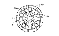
- the coherent light source has a plurality of light emitting units that emit a plurality of coherent lights having different emission wavelength ranges, At least one of the first diffusion region and the second diffusion region may have a plurality of diffusion region portions scanned by the plurality of coherent lights.
- the optical element is a hologram recording medium;
- Each of the first diffusion region and the second diffusion region may have an element hologram region in which different interference fringe patterns are formed.
- the optical element is a lens array group having a plurality of lens arrays, Each of the first diffusion region and the second diffusion region may have the lens array.
- the optical element has a hologram recording medium and a lens array group having a plurality of lens arrays,
- One of the first diffusion region and the second diffusion region may include the hologram recording medium, and the other may include the lens array group.
- the timing control unit controls the timing at which the coherent light from the scanning unit is continuously scanned on the first diffusion region and the coherent light from the scanning unit is scanned on the second diffusion region. Also good.
- the timing control unit may control the timing at which the coherent light from the scanning unit is scanned on the second diffusion region based on the information selected by the information selection unit.
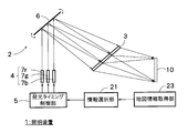
- a route information acquisition unit that acquires route information to be traveled is provided.
- the information selection unit may select the information to be displayed in the second range based on the route information acquired by the route information acquisition unit.
- the information selection unit may select the information capable of identifying at least one of a direction to travel and a direction not to travel based on the route information acquired by the route information acquisition unit.
- the information selection unit may select the information in a display mode in which one candidate route to be traveled among a plurality of candidate routes and another candidate route can be identified.
- the information selection unit may select information for displaying one candidate route to be traveled among a plurality of candidate routes and other candidate routes using colors different from each other.
- the information selection unit may select the information around the current position based on the map information acquired by the map information acquisition unit.
- the optical path length of coherent light from the optical element to the first range may be longer than the optical path length of coherent light from the optical element to the second range.
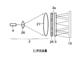
- a beam diameter expanding member for expanding the beam diameter of the coherent light An optical shutter that switches the transmittance of the coherent light incident on the optical element or the coherent light diffused by the optical element,
- the optical element has a plurality of element diffusion regions that each independently diffuse coherent light whose beam diameter is expanded by the beam diameter expanding member,
- the optical shutter has a plurality of element shutter portions corresponding to the plurality of element diffusion regions, Each of the plurality of element shutters may switch the transmittance of coherent light incident on the corresponding element diffusion region or coherent light diffused in the corresponding element diffusion region.
- the optical shutter is disposed closer to the optical element on the optical axis front side than the optical element,
- Each of the plurality of element shutter portions may switch the transmittance of coherent light incident on the corresponding element diffusion region.
- the optical shutter is disposed close to the optical element on the optical axis rear side of the optical element,
- Each of the plurality of element shutter portions may switch the transmittance of the coherent light diffused from the corresponding element diffusion region.
- the optical shutter may switch the illumination mode for each partial area within a predetermined illumination range illuminated by each of the plurality of element diffusion areas by individually switching the plurality of element shutters.
- the illumination mode may be illumination intensity for each partial area or whether or not each partial area is illuminated.
- the coherent light source has a plurality of light source units that emit a plurality of coherent lights having different emission wavelength ranges
- the optical element includes a plurality of diffusion regions including the first diffusion region and the second diffusion region, which are provided corresponding to each of the plurality of coherent lights and into which the corresponding coherent light is incident.
- Each of the plurality of diffusion regions has the plurality of element diffusion regions
- the optical shutter may include the plurality of element shutter portions corresponding to the plurality of element diffusion regions for each of the plurality of diffusion regions.
- the optical shutter may switch the illumination color of the entire illumination range by switching the plurality of element shutter portions provided for each of the plurality of diffusion regions as a set.
- the optical shutter switches each of the plurality of element shutter portions provided for each of the plurality of diffusion areas, thereby individually illuminating each of the plurality of element diffusion areas.
- the lighting mode may be switched.
- the illumination mode may include an illumination color for each partial area.
- the optical shutter can switch the transmittance of the coherent light whose beam diameter is expanded stepwise or continuously,
- Each of the plurality of element shutter portions may individually switch the amount of incident coherent light to the corresponding element diffusion region or the amount of transmitted coherent light diffused in the corresponding element diffusion region.
- the optical shutter may be a mechanical shutter, an electronic shutter, or a multi-cell shutter.
- the imaging element shutter has a plurality of liquid crystal cells corresponding to the plurality of element shutter portions, and changes the alignment direction of liquid crystal molecules for each of the plurality of liquid crystal cells to enter the corresponding element diffusion region. It may be a liquid crystal shutter that switches the transmittance of the coherent light to be transmitted or the coherent light diffused in the corresponding element diffusion region.
- the coherent light diffused in the first diffusion region of the optical element illuminates the first range
- the first diffusion region may include the plurality of element diffusion regions.
- the coherent light diffused in the second diffusion region of the optical element displays predetermined information in the second range
- the second diffusion region may have one or more element diffusion regions.
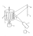
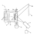
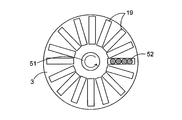
- a drive unit for moving the optical element The optical element holds a plurality of diffusion regions including the first diffusion region and the second diffusion region, The drive unit moves the optical element so that each of the plurality of diffusion regions sequentially reaches an irradiation position of coherent light from the coherent light source, Each of the plurality of diffusion regions illuminates a corresponding partial region within a predetermined illumination range by diffusing the incident coherent light, and at least one of the partial regions illuminated by each of the plurality of diffusion regions. Each part may be different.
- a timing control unit may be provided for controlling the incident timing of the coherent light from the coherent light source to the optical element or the illumination timing of the illumination range.
- the drive unit is configured to continuously rotate the optical element in a rotation direction,
- the plurality of diffusion elements may be arranged along the rotation direction.
- the optical element may have a disk shape.
- the optical element may have a cylindrical shape.
- the optical element has a set of rotating rollers that can rotate around each axis, and a belt-shaped portion that is looped around the set of rotating rollers,
- the plurality of diffusion elements are arranged along the longitudinal direction of the strip-shaped portion,
- the driving unit may be configured to continuously rotate at least one rotating roller around its axis.
- Each of the plurality of diffusion elements has an elongated shape extending in a direction perpendicular to the moving direction of the optical element
- the coherent light source may include a laser array arranged in a direction perpendicular to the moving direction of the optical element.
- An object detection unit for detecting an object existing within a predetermined illumination range illuminated by the optical element;
- the timing controller is configured to detect the optical of the coherent light from the coherent light source so that a region of the object detected by the object detector and another region in the illumination range are different from each other. You may control the incident timing to an element, or the illumination timing of the said illumination range.
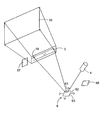
- the object detection unit includes: An imaging device that images within a predetermined illumination range illuminated by the optical element; And an image processing unit that performs image processing on an imaging result of the imaging device and recognizes an object within a predetermined illumination range illuminated by the optical element.
- the object detection unit includes: A position information acquisition unit for acquiring position information of a vehicle in which the lighting device is installed; A storage unit for storing position information of the object; Recognizing an object within a predetermined illumination range illuminated by the optical element based on the vehicle position information acquired by the position information acquisition unit and the position information of the object stored in the storage unit And an information processing unit that performs the processing.
- a steering wheel rotation detector for detecting rotation of a steering wheel of a vehicle in which the lighting device is installed;
- the timing control unit controls the incidence timing of the coherent light from the coherent light source to the optical element or the illumination timing of the illumination range based on the rotation of the handle detected by the handle rotation detection unit. May be.
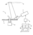
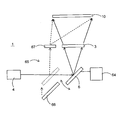
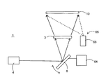
- An operation monitoring unit for monitoring the operation of the scanning unit And an auxiliary illumination unit that illuminates a predetermined illumination range illuminated by the optical element when the operation monitoring unit detects a change in the operation of the scanning unit.
- the auxiliary illumination unit is An auxiliary mirror disposed in an optical path between the coherent light source and the scanning unit when a change in the operation of the scanning unit is detected by the operation monitoring unit; An auxiliary optical element that diffuses the coherent light to illuminate the illumination range; Have The auxiliary mirror may cause the coherent light from the coherent light source to enter the auxiliary optical element.
- the auxiliary optical element may illuminate the entire illumination range by diffusing incident coherent light.
- the auxiliary optical element may be a hologram recording medium.
- the auxiliary illumination unit is An auxiliary mirror disposed in an optical path between the coherent light source and the scanning unit when an abnormality in the operation of the scanning unit is detected by the operation monitoring unit;
- the auxiliary mirror may cause the coherent light from the coherent light source to enter the optical element.
- the auxiliary illumination unit may have a light source different from the coherent light source.
- a coherent light source that emits coherent light
- a beam diameter expanding member for expanding the beam diameter of the coherent light
- An optical element that diffuses coherent light with a wide beam diameter and illuminates a predetermined range
- An optical shutter that switches the transmittance of the coherent light incident on the optical element or the coherent light diffused by the optical element
- the optical element has a plurality of element diffusion regions that each independently diffuse coherent light
- the optical shutter has a plurality of element shutter portions corresponding to the plurality of element diffusion regions, Each of the plurality of element shutter units is provided with an illumination device that switches the transmittance of coherent light incident on the corresponding element diffusion region or coherent light diffused in the corresponding element diffusion region.
- a coherent light source that emits coherent light
- Diffusion means for holding a plurality of diffusion elements for diffusing the coherent light
- Driving means for moving the diffusing means so that each of the plurality of diffusing elements sequentially reaches the irradiation position of the coherent light
- a coherent light source that emits coherent light
- a diffusion element that diffuses the coherent light and illuminates a predetermined range
- Optical scanning means for scanning the coherent light from the coherent light source on the diffusing element
- Operation monitoring means for monitoring the operation of the optical scanning means
- An auxiliary illumination unit that illuminates the predetermined range when a change in the operation of the optical scanning unit is detected by the operation monitoring unit;
- the diffusing element has a plurality of element diffusion regions, and each of the plurality of element diffusion regions illuminates a corresponding partial region within the predetermined range by diffusing incident coherent light, and the plurality of elements At least some of the partial areas illuminated by each of the diffusion areas are provided with different illumination devices.
- an illumination device that can arbitrarily change the illumination mode of an arbitrary region within the illumination range without complicating the configuration of the optical system.
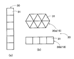
- (A) And (b) is a figure which shows the specific example of a hologram recording medium.
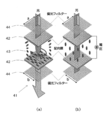
- (A) And (b) is a figure which illuminates one illumination range with multiple colors.
- the figure which shows the illumination range illuminated with the illuminating device of FIG. The figure which shows the example illuminated so that a target object may be avoided.
- (A)-(c) is a figure which shows the specific example of the information of the 2nd range displayed using a headlight.
- each element diffusion area in the second diffusion area performs rectangular illumination.
- the figure which shows schematic structure of the illuminating device which shows the 1st modification of FIG. The figure which shows schematic structure of the illuminating device which shows the 2nd modification of FIG.
- (A) And (b) is a figure which shows the structure of one liquid crystal cell typically.
- the figure which shows the example which performs illumination and information display within an illuminated area The figure which shows schematic structure of the illuminating device which made arrangement
- FIG. 42 is a plan view showing diffusing means in the illumination device of FIG. 41.
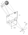
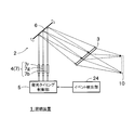
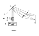
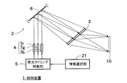
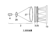
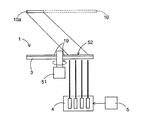
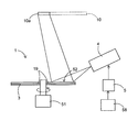
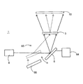
- FIG. 1 is a diagram showing a schematic configuration of a lighting device 1 according to a first embodiment of the present invention.
- the illumination device 1 in FIG. 1 includes an irradiation device 2 and an optical element 3.
- the irradiation device 2 includes a laser light source 4 and a scanning unit 6.
- the laser light source 4 emits coherent light, that is, laser light.
- the laser light source 4 may be provided with a plurality of light source units having different emission wavelength ranges, but may be configured to include one or more light source units that emit laser light in a single wavelength range. In the present embodiment, an example in which one or more light source units that emit laser light in a single wavelength region are provided will be described.
- the scanning unit 6 scans a plurality of laser beams emitted from the laser light source 4 on the optical element 3.
- the scanning unit 6 may move the laser light source 4 to scan each laser beam on the optical element 3, or may move the optical element 3 to scan each laser beam on the optical element 3.
- an optical scanning member that changes the traveling direction of the laser light from the laser light source 4 may be provided, and each laser light may be scanned on the optical element 3.
- the technical features of the scanning unit 6 are common to the following embodiments, but in each of the following embodiments, an example in which the scanning unit 6 includes an optical scanning member will be mainly described. 6 ”.
- the optical scanning member 6 changes the traveling direction of the laser light from the laser light source 4 with time so that the traveling direction of the laser light does not become constant. As a result, the laser light emitted from the optical scanning member 6 scans the incident surface of the optical element 3.
- the optical scanning member 6 includes a reflection device 13 that can rotate around two rotation axes 11 and 12 that extend in directions intersecting each other.
- the laser light from the laser light source 4 incident on the reflection surface 13a of the reflection device 13 is reflected at an angle corresponding to the inclination angle of the reflection surface 13a and travels in the direction of the incident surface 3a of the optical element 3.
- the reflection device 13 repeats the operation of rotating around the two rotation axes 11 and 12 at a constant period.
- the laser light repeatedly two-dimensionally scans the incident surface 3a of the optical element 3 in synchronization with this period.
- the optical element 3 may perform one-dimensional scanning along the longitudinal direction of the optical element 3.
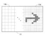
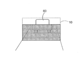
- the optical element 3 has an incident surface 3a on which laser light is incident, and diffuses the laser light incident on the incident surface 3a to illuminate a predetermined range. More specifically, the laser light diffused by the optical element 3 illuminates a predetermined range after passing through the illuminated area 10.
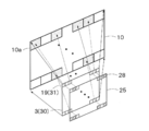
- the illuminated area 10 in FIG. 2 is a near-field illuminated area that is illuminated by the respective diffusion areas 14 in the optical element 3.
- the far field illumination range is often expressed as a diffuse angle distribution in the angle space rather than the actual size of the illuminated area.
- the term “illuminated area” includes a diffusion angle range in an angle space in addition to an actual irradiated area (illumination range). Therefore, the predetermined range illuminated by the illumination device of FIG. 1 can be a much wider area than the illuminated area 10 of the near field shown in FIG.
- the first range 15 and the second range 17 are included in the predetermined range.
- the first range 15 and the second range 17 may be arranged so as not to overlap each other, or may be arranged so that at least a part thereof overlaps. Further, at least one of the first range 15 and the second range 17 may be provided at a plurality of locations.
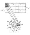
- the optical element 3 includes a first diffusion region 16 that illuminates the first range 15 and a second diffusion region 18 that displays predetermined information in the second range 17.
- the first range 15 and the second range 17 are ranges illuminated by the laser light that has passed through the illuminated area 10 in FIG. 1 and are provided on the ground, for example.
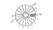
- At least one of the first diffusion region 16 and the second diffusion region 18 in the optical element 3 may be further divided into a plurality of element diffusion regions 19.
- FIG. 2 shows an example in which each of the first diffusion region 16 and the second diffusion region 18 is divided into a plurality of element diffusion regions 19, but this is only an example.
- the simplest configuration is when the optical element 3 has a first diffusion region 16 composed of one element diffusion region 19 and a second diffusion region 18 composed of another element diffusion region 19.
- the laser light from the optical scanning member 6 scans the optical element 3. More specifically, the optical scanning member 6 sequentially scans the element diffusion regions 19 constituting the first diffusion region 16 and the second diffusion region 18.
- Each element diffusion region 19 in the first diffusion region 16 illuminates a partial region in the first range 15. If the first diffusion region 16 has only one element diffusion region 19, this element diffusion region 19 illuminates the entire area of the first range 15. In some cases, each of the two or more element diffusion regions 19 included in the first diffusion region 16 may illuminate the entire first range 15.
- each element diffusion region 19 in the second diffusion region 18 displays information in the second range 17. When the second diffusion region 18 has only one element diffusion region 19, this element diffusion region 19 displays all the information in the second range 17. When a plurality of element diffusion regions 19 are included in the second diffusion region 18, each element diffusion region 19 may share and display one information in the second range 17. 19 may display separate information in the second range 17.
- the illumination in the first range 15 may illuminate the entire area within the first range 15 with uniform illuminance, or may illuminate with non-uniform illuminance that varies depending on the location.
- the central part of the first range 15 may be brightest and darker as it goes away from the central part.
- the information displayed in the second range 17 is information in which at least one of hue, brightness, and saturation is changed in the second range 17. More specifically, the information displayed in the second range 17 is, for example, at least one of a pattern, a pattern, characters, numbers, and symbols, and the specific content of the information is not particularly limited.
- the information display in the second range 17 is performed, for example, for the purpose of giving design or decoration, for the purpose of calling attention, for the purpose of displaying guidance, for the purpose of advertising. Further, the information displayed in the second range 17 may be a single color (monochrome) or a plurality of colors (color), but in this embodiment, an example of displaying information in a single color will be described.
- the optical element 3 is configured using, for example, a hologram recording medium 30.
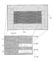
- the hologram recording medium 30 has a plurality of element hologram regions 31 corresponding to the plurality of element diffusion regions 19.
- an interference fringe pattern is formed in each element hologram region 31, an interference fringe pattern is formed.
- the laser light is diffracted by the interference fringe pattern, passes through the illuminated region 10, and illuminates the first range 15 and the second range 17. To do.
- an interference fringe pattern corresponding to the element hologram area 31 is formed in advance so that the laser light diffracted in the element hologram area 31 illuminates the first area 15. Keep it.
- the interference fringe pattern corresponding to the element hologram area 31 is displayed so that the laser light diffracted in the element hologram area 31 displays information in the second range 17. Is formed in advance.
- the position, size and shape of the first range 15 can be arbitrarily set by adjusting the interference fringe pattern formed in the element hologram region 31 for the first diffusion region 16.
- the interference fringe pattern formed in the element hologram region 31 for the second diffusion region 18 can be arbitrarily set. Can be set.
- the laser light incident on each point in each element hologram region 31 illuminates the corresponding first range 15 or second range 17. Further, the optical scanning member 6 changes the incident position and incident angle of the laser light incident on each element hologram region 31 over time.
- the laser beam incident on one element hologram region 31 illuminates the common first range 15 or second range 17 regardless of the position in the element hologram region 31. This means that the incident angle of the laser beam incident on each point of the partial region 10a changes with time.
- the change in the incident angle is a speed that cannot be resolved by the human eye, and as a result, a non-correlated coherent light scattering pattern is multiplexed and observed in the human eye. Therefore, speckles generated corresponding to each scattering pattern are overlapped and averaged and observed by an observer.
- the shape of the element hologram area 31 is rectangular, but the shape of the element hologram area 31 is arbitrary.
- the shapes and sizes of the first range 15 and the second range 17 illuminated by the laser light diffused in the element hologram region 31 depend on the type of interference fringe pattern formed in the element hologram region 31, and the element hologram region 31 It does not depend on the shape or size. Therefore, the shape and size of the element hologram region 31 may be arbitrary. However, the element hologram region 31 needs to have a size and a shape capable of scanning with laser light.
- FIG. 3A shows an example of a hologram recording medium 30 in which a plurality of element hologram regions 31 are arranged adjacent to each other in the vertical direction.
- FIG. 3B shows a hologram recording medium composed of an element hologram area group 30a in which triangular element hologram areas 31 are arranged without gaps and an element hologram area group 30b in which a plurality of element hologram areas 31 are arranged adjacently in the horizontal direction.
- the example which comprises 30 is shown.
- one of the two element hologram region groups 30a and 30b corresponds to the first diffusion region 16, and the other corresponds to the second diffusion region 18.
- 3A and 3B can perform illumination of the first range 15 and information display of the second range 17 in either hologram recording medium 30 shown in FIG. That is, the arrangement and shape of each element hologram area 31 group constituting the hologram recording medium 30 is arbitrary, and by adjusting the interference fringe pattern formed in each element hologram area 31, the illumination in the first range 15 described above can be achieved. Information display of the second range 17 can be performed.
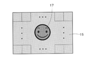
- FIG. 2 shows an example in which the first range 15 and the second range 17 are provided in different places, but the second range 17 may be provided in the first range 15 as shown in FIG.
- information display of the second range 17 is performed inside the illumination area within the first range 15.
- where to set the first range 15 and the second range 17 can be arbitrarily adjusted according to the type of interference fringe pattern formed in each element hologram region 31.
- each element hologram region 31 in the first diffusion region 16 illuminates a partial region in the first range 15 (a rectangle surrounded by a broken line in FIG. 4), and the aggregate of these partial regions
- the example which performs illumination of the 1st range 15 is shown. This is an example, and as described above, each element hologram region 31 may illuminate the entire first range 15, or some of the element hologram regions 31 may illuminate different partial regions and the rest.
- the element hologram area 31 may be illuminated by overlapping the same partial area. When a plurality of element hologram areas 31 are overlapped and illuminated, the illumination illuminance in that area increases, so a pattern or a pattern can be displayed by mixing the overlapping illumination area and the non-overlapping illumination area. can do.
- Each element hologram region 31 for the first diffusion region 16 can be produced using, for example, scattered light from a real scattering plate as object light. More specifically, when the hologram photosensitive material which is the base material of the hologram recording medium 30 is irradiated with reference light and object light made of coherent light having interference with each other, an interference fringe pattern due to interference of these lights is generated in the hologram photosensitive material. In this way, the hologram recording medium 30 is manufactured.
- reference light laser light which is coherent light is used, and as object light, for example, scattered light from an isotropic scattering plate available at low cost is used.
- the hologram recording medium 30 By irradiating the hologram recording medium 30 with laser light from the focal position of the reference light used when producing the hologram recording medium 30, scattering that is the source of the object light used when producing the hologram recording medium 30 A reproduced image of the scattering plate is generated at the position of the plate. If the scattering plate that is the source of the object light used when producing the hologram recording medium 30 has a uniform surface scattering, the reproduced image of the scattering plate obtained by the hologram recording medium 30 also has a uniform surface illumination. The area where the reproduced image of the scattering plate is generated is the illuminated area 10.
- Each element hologram region 31 for the second diffusion region 18 for displaying information in the second range 17 in the hologram recording medium 30 is interfered in the same procedure as described above using a scattering plate on which an information image has been formed in advance.
- a stripe pattern can be formed.
- the hologram recording medium 30 has to perform illumination of the first range 15 and information display of the second range 17, and the interference fringe pattern becomes complicated.
- a complex interference fringe pattern can be obtained by using a computer based on the planned wavelength and incident direction of the reproduction illumination light and the shape and position of the image to be reproduced without using actual object light and reference light. Can be used to design.
- the hologram recording medium 30 obtained in this way is also called a computer generated hologram (CGH).
- a Fourier transform hologram having the same diffusion angle characteristic at each point on each element hologram region 31 may be formed by computer synthesis.
- an optical member such as a lens may be provided on the rear side of the optical axis of the illuminated area 10 to set the size and position of the actual illumination range.
- the hologram recording medium 30 as the optical element 3 is that the light energy density of the laser beam can be reduced by diffusion.
- the hologram recording medium 30 has directivity. Since it can be used as a surface light source, the luminance on the light source surface for achieving the same illuminance distribution can be reduced as compared with a conventional lamp light source (point light source). As a result, the safety of the laser beam can be improved, and even if the laser beam that has passed through the illuminated region 10 is directly viewed by the human eye, the human eye is adversely affected as compared with the case where the single point light source is directly viewed. The fear is reduced.
- FIG. 1 shows an example in which the laser light from the optical scanning member 6 is transmitted through the optical element 3 and diffuses, but the optical element 3 may be one that diffuses and reflects the laser light.
- the hologram recording medium 30 may be a reflection type or a transmission type.
- the reflection type hologram recording medium 30 (hereinafter referred to as reflection type holo) has higher wavelength selectivity than the transmission type hologram recording medium 30 (hereinafter referred to as transmission type holo). That is, the reflection type holo can diffract coherent light having a desired wavelength only by a desired layer even if interference fringe patterns corresponding to different wavelengths are laminated.
- the reflection type holo is also excellent in that it is easy to remove the influence of zero-order light.
- the transmission type holo has a wide diffractable spectrum and a wide tolerance of the laser light source 4.
- interference fringe patterns corresponding to different wavelengths are laminated, coherent light having a desired wavelength can be obtained in layers other than the desired layer. Will be diffracted. Therefore, in general, it is difficult to make the transmission type holo a laminated structure.
- a volume hologram recording medium 30 using a photopolymer may be used, or a volume hologram recording medium 30 of a type for recording using a photosensitive medium containing a silver salt material.
- a relief (embossed) hologram recording medium 30 may be used.
- the specific form of the optical element 3 is not limited to the hologram recording medium 30 and may be various diffusion members that can be finely divided into a plurality of element diffusion regions 19.
- the optical element 3 may be configured using a lens array group in which each element diffusion region 19 is a single lens array.
- a lens array is provided for each element diffusion region 19, and the shape of each lens array is designed so that each lens array illuminates the partial region 10 a in the illuminated region 10.
- the positions of the partial areas 10a are at least partially different. Thereby, illumination of the first range 15 and information display of the second range 17 can be performed as in the case where the optical element 3 is configured using the hologram recording medium 30.
- the outer shape of the lens array may be an arrow shape.
- an arbitrary orientation distribution for information can be formed by each lens array.
- the optical element 3 may be configured by combining the hologram recording medium 30 and a lens array. That is, one of the first diffusion region 16 and the second diffusion region 18 may be configured by the hologram recording medium 30 and the other may be configured by a lens array group.
- the illumination device 1 can be provided that takes into account functions such as design by design of information, decoration, and practicality.
- the optical scanning member 6 scans the laser light in each element diffusion region 19, and the laser light incident on each point in each element diffusion region 19 is one of the corresponding first range 15 or second range 17.
- the incident angle of the laser beam in the first range 15 or the second range 17 changes with time, and speckles in the first range 15 or the second range 17 are less noticeable. .
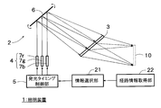
- FIG. 5 is a diagram showing a schematic configuration of the illumination device 1 according to the second embodiment of the present invention.
- the illumination device 1 in FIG. 5 is different from FIG. 1 in that a timing control unit 5 is provided inside the irradiation device 2.
- the laser light source 4 in FIG. 5 includes a plurality of light source units 7 that emit a plurality of coherent lights, that is, laser lights, having different emission wavelength ranges.
- the plurality of light source units 7 may be provided independently, or may be a light source module in which a plurality of light source units 7 are arranged side by side on a common substrate.
- the laser light source 4 of this embodiment should just have the at least 2 light source part 7 from which each light emission wavelength range differs, and the kind of light emission wavelength range should just be 2 or more.
- a plurality of light source units 7 may be provided for each emission wavelength region.
- the laser light source 4 includes a light source unit 7r in the red light emission wavelength region, a light source unit 7g in the green light emission wavelength region, and a light source unit 7b in the blue light emission wavelength region, these light source units 7 By superimposing the three laser beams emitted by, white illumination light can be generated.
- the second embodiment it is not essential to provide a plurality of light source units 7 each having a different emission wavelength range.
- one or more light sources that emit laser light in a single wavelength range.
- the light source unit 7 may be provided. Below, the example which provides the some light source part 7 from which each light emission wavelength range differs is demonstrated.
- the timing control unit 5 individually controls the incident timing of the plurality of coherent lights to the optical element 3 or the illumination timing of the illuminated area (illumination range) 10.
- the timing control unit 5 may control the light emission timing from the laser light source 4, may control the incident timing of the laser light incident on the optical element 3, or is diffused by the optical element 3. You may control the illumination timing which a laser beam illuminates the illumination range.
- the timing controller 5 synchronizes with the scanning timing of the laser beam (coherent light) by the optical scanning member 6 so that the illumination mode of the illuminated area (illumination range) 10 changes periodically or temporarily.
- the light emission timing, the incident timing to the optical element 3, or the illumination timing of the illumination range are individually controlled.
- the above-described technical features of the timing control unit 5 are common to the following embodiments. In each of the following embodiments, an example in which the timing control unit 5 controls the light emission timing from the laser light source 4 will be mainly described. To do.
- the timing control unit 5 controls whether or not the coherent light from the optical scanning member 6 is scanned in at least one of the first diffusion region 16 and the second diffusion region 18.
- the timing control unit 5 may be configured to switch whether or not the first diffusion region 16 is continuously scanned and at least a part of the second diffusion region 18 is scanned.
- the first range 15 can be constantly illuminated, and the second range 17 can display information only when necessary.
- the timing control unit 5 may switch whether or not at least a part of the first diffusion region 16 is scanned, and may continuously scan the second diffusion region 18.
- the timing controller 5 individually controls the timings of a plurality of laser beams having different emission wavelength ranges. That is, when a plurality of light source units 7 are provided corresponding to a plurality of laser beams having different emission wavelength ranges, the timing control unit 5 determines the timing of emitting the laser beams from the plurality of light source units 7. Control is performed for each light source unit 7. As described above, when the laser light source 4 can emit three laser beams of red, blue, and green, the timing of each laser beam is controlled to mix any one or more colors of red, blue, and green. It is possible to generate illumination light of different colors.
- the timing control unit 5 may control whether or not to emit laser light from each light source unit 7, that is, on / off of light emission, and the laser light emitted from each light source unit 7 may be emitted from the optical scanning member 6. Whether or not to guide light to the incident surface may be switched. In the latter case, an optical shutter unit (not shown) may be provided between each light source unit 7 and the optical scanning member 6, and the passage / blocking of the laser light may be switched by this optical shutter unit.
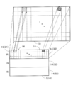
- FIG. 6 is a diagram illustrating a state in which the laser light diffused by the optical element 3 is incident on the illuminated area 10.
- the optical element 3 has a plurality of diffusion region portions 14 corresponding to a plurality of laser beams. Corresponding laser light is incident on each diffusion region portion 14.
- Each diffusion region portion 14 includes a first diffusion region 16 and a second diffusion region 18 as in the first embodiment.
- the arrangement order of the first diffusion region 16 and the second diffusion region 18 in each diffusion region portion 14 is arbitrary, and the ratio of the first diffusion region 16 and the second diffusion region 18 in each diffusion region portion 14 is also arbitrary.
- Each diffusion region portion 14 diffuses the incident laser light to illuminate the entire illuminated region 10.
- Each diffusion region portion 14 has a plurality of element diffusion regions 19.
- Each element diffusion region 19 diffuses incident laser light to illuminate a partial region in the illuminated region 10. At least a part of the partial region is different for each element diffusion region 19.
- the optical element 3 is configured using, for example, a hologram recording medium 30.
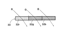
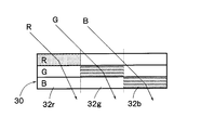
- the hologram recording medium 30 has a plurality of hologram regions 32 as shown in FIG. Each hologram region 32 is provided corresponding to each of a plurality of laser beams having different emission wavelength ranges. Any laser light that has been incident and diffused on the incident surface of each hologram region 32 illuminates the illuminated region 10. For example, when the hologram recording medium 30 has three hologram areas 32, the laser light diffused in each hologram area 32 illuminates the entire illuminated area 10.
- FIG. 6 shows an example in which three hologram regions 32 corresponding to the three diffusion region portions 14 are provided in association with the three laser beams emitting red, blue, or green, but the hologram recording according to the present embodiment.
- the medium 30 only needs to have two or more hologram regions 32 in association with two or more laser beams having different emission wavelength ranges.
- each hologram region 32 illuminates the entire illuminated region 10. Therefore, when three laser beams are emitted, the illuminated area 10 is illuminated in white.
- the size that is, the area of each hologram region 32 in the hologram recording medium 30 is not necessarily the same. Even if the sizes of the hologram regions 32 are different, the hologram regions 32 can be shared by adjusting the interference fringe pattern formed on the incident surface 17a of each hologram region 32 for each hologram region 32. Can be illuminated.
- Each of the plurality of hologram areas 32 has a plurality of element hologram areas 31.
- Each element hologram region 31 is the first diffusion region 16 or the second diffusion region 18.
- Each element hologram region 31 illuminates the partial region 10a in the illuminated region 10 by diffusing the incident laser light. At least a part of the partial area illuminated by each element hologram area 31 is different for each element hologram area 31. That is, the partial areas 10a illuminated by different element hologram areas 31 are at least partially different.
- the partial area illuminated by the element hologram area 31 corresponding to the first diffusion area 16 illuminates the first range 15 after passing through the illuminated area 10.
- the partial area illuminated by the element hologram area 31 corresponding to the second diffusion area 18 displays information in the second range 17 after passing through the illuminated area 10.
- the lighting device 1 since the lighting device 1 according to the present embodiment includes the timing control unit 5, at least one of illumination in the first range 15 and information display in the second range 17 can be performed at an arbitrary timing.
- the scanning timing of the laser beam in an arbitrary hologram region among the hologram regions provided for each color a part of the illumination range illuminated by the laser beam that has passed through the illuminated region 10 It is possible to perform illumination control as necessary, changing the illumination color or not illuminating only a part of the illumination range.
- the example in which the timing for performing at least one of the illumination in the first range 15 and the information display in the second range 17 is switched or the illumination color is changed according to the timing is shown.
- There are other methods for changing the illumination mode of the part For example, when the laser light source 4 has a plurality of light source units 7 that emit light in the same emission wavelength region, the light emission of some of the light source units 7 is stopped, and a part of the illumination in the illuminated area 10 The intensity may be lower than the surrounding illumination intensity. Conversely, a part of the illumination intensity in the illuminated area 10 may be higher than the surrounding illumination intensity. Further, a part of the illuminated area 10 may be blinked. Or you may change the one part color in the to-be-illuminated area
- each element hologram region 31 corresponding to the first diffusion region 16 illuminates within the first range 15 may at least partially overlap.
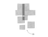
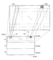
- FIG. 7 shows an example in which a part of each rectangular illumination range in the first range 15 overlaps. If a part of each illumination range illuminated by each element hologram region 31 overlaps, the illuminance of the overlapped part becomes higher, so that even if the illumination color is the same, it becomes easily noticeable. By characterizing the shape and size of the overlapping portions, it is possible to provide design.
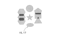
- FIG. 8 is a diagram illustrating an example in which a plurality of types of illumination ranges illuminated by each element hologram region 31 are provided.
- illumination ranges of a plurality of shapes such as a polygon, a circle, and a star
- FIG. 8 by overlapping a part of the illumination range, a part of the illumination range can be made conspicuous similarly to FIG.
- FIG. 8 is applicable to any illumination shape in the first range 15 and the second range 17.
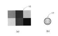
- FIG. 9A shows an example in which illumination in the first range 15 is performed in a plurality of colors
- FIG. 9B shows an example in which information display in the second range 17 is performed in a plurality of colors.
- the timing control unit 5 can arbitrarily control the timing of the laser beam that scans the optical element 3, so that the illumination in the first range 15 and the information display in the second range 17 can be performed. At least one of the above can be performed at an arbitrary timing. In addition, at least one of the illumination mode of the first range 15 and the illumination mode of information display of the second range 17 can be switched at an arbitrary timing.
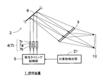
- FIG. 10 is a diagram showing a schematic configuration of the illumination device 1 according to the third embodiment of the present invention
- FIGS. 11 and 12 are diagrams showing an illumination range illuminated by the illumination device 1 of FIG.
- the illumination device 1 in FIG. 10 includes an object detection unit 21 in addition to the configuration of the illumination device 1 in FIG.
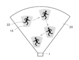
- the object detection unit 21 detects an object 22 existing within a predetermined range 23 that can be illuminated by the optical element 3. That is, the target object detection unit 21 detects the target object 22 present in the illumination range 23 that can be illuminated by the laser light that has passed through the illuminated area 10 of FIG.
- the target 22 is a human, a vehicle, a living thing, etc., and the target may be a moving body or a stationary body.
- the object detection unit 21 may be a sensor that optically detects the object 22.
- the presence or absence of the object 22 and the position and size of the object 22 are detected by irradiating the illuminated area 10 with infrared light from the sensor and whether or not the reflected light is detected within a predetermined time by the sensor. May be.
- an image of the illuminated area 10 may be taken by a camera, and the taken image may be analyzed by image recognition such as pattern matching to detect the presence / absence of the target 22 and the position and size of the target 22.
- the timing control unit 5 controls the timing of the plurality of light source units 7 in accordance with the position and size of the target object 22 when the target object detection unit 21 detects the target object 22. More specifically, the timing control unit 5 controls the scanning timing of the laser light in the first diffusion region 16 so that only the periphery of the object 22 is illuminated.
- FIG. 11 shows an example in which the position of the first range 15 is moved in accordance with the movement of the object 22 to illuminate the periphery of the object 22.
- the arrow line in FIG. 11 indicates the movement path of the object 22.
- the periphery of the target object 22 can be illuminated, always tracking the target object 22.
- FIG. 11 shows an example in which the object 22 is always illuminated with the same color, the object 22 may be illuminated with a different color depending on the position of the object 22. Even when the illumination color is changed, it can be easily realized by the timing control unit 5 individually controlling the timings of the plurality of light source units 7.
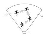
- FIG. 12 shows an example in which illumination is performed so as to avoid the object 22, contrary to FIG. 11.
- FIG. 12 can be used to grasp the movement path of the object 22 by illuminating the path through which the object 22 has passed.
- the timing control unit 5 controls the scanning timing of the laser light that scans the first diffusion region 16 according to the position of the target 22 detected by the target detection unit 21, thereby Illumination that avoids the object 22 can be performed by moving the first range 15 in accordance with the movement of the object 22.
- the method of changing the illumination mode according to the position of the target object 22 detected by the target object detection unit 21 is not limited to the examples shown in FIGS.
- the direction in which the object 22 moves may be predicted, and an area where the object 22 may move may be illuminated.
- the illumination of the first range 15 or the information display of the second range 17 is performed in accordance with the movement of the target object 22, it becomes easy to grasp the movement location of the target object 22, Further, it is possible to always provide desired information to the moving object 22.
- FIG. 13 is a diagram showing a schematic configuration of the illumination device 1 according to the fourth embodiment of the present invention.
- the illuminating device 1 of FIG. 13 provides the event detection part 24 in the illuminating device 1 of FIG.
- the event detection unit 24 detects that a specific event has occurred.
- the specific event is, for example, when the vehicle lighting device 1 is turned on or off, or when a door is opened or closed.
- the timing control unit 5 controls the timing of the plurality of light emitting units 7.
- the illuminating device 1 is a vehicle headlight, for example, while the vehicle is moving, the first range 15 is illuminated and used for normal illumination purposes, and the vehicle is stopped.
- information on the second range 17 can be displayed with a headlight.
- the displayed information is arbitrary, but for example, displaying the vehicle brand name, manufacturer name, car model name, etc. as information can also promote the vehicle and give the vehicle owner a sense of superiority. .
- the lighting device 1 In addition to the headlight, if the lighting device 1 is provided in the vicinity of the vehicle door, when the event that the door is opened occurs, the lighting that draws the eye of the passenger near the place where the passenger gets off the vehicle And information display, and a high-class feel of the vehicle.
- the illumination in the first range 15 and the information display in the second range 17 is performed or the illumination and the information display are switched.
- Lighting can be used for purposes such as advertising, alerting, and improving design.
- the vehicle on which the lighting device 1 according to the first to fourth embodiments described above is mounted is not necessarily limited to a vehicle, and may be a flying object such as an aircraft, various moving objects such as a train, a ship, and a diving object. .
- the illuminating device 1 is not limited to what was mounted in the vehicle, The thing installed in arbitrary places may be sufficient.
- FIG. 14 is a diagram showing a schematic configuration of a lighting apparatus 1 according to the fifth embodiment of the present invention.
- the illuminating device 1 in FIG. 14 includes an irradiation device 2 and an optical element 3.
- the irradiation device 2 includes a laser light source 4, a timing control unit 5, and an optical scanning member 6.
- the laser light source 4 has a light source unit 7 that emits coherent light in a predetermined emission wavelength range, that is, laser light.
- a predetermined emission wavelength range that is, laser light.
- the plurality of light source units 7 may be provided independently, or may be a light source module in which a plurality of light source units 7 are arranged side by side on a common substrate.
- the laser light source 4 of this embodiment should just have the at least 1 light source part 7.
- a plurality of light source units 7 that emit laser light in a common emission wavelength region may be provided.
- the laser light source 4 includes a light source unit 7r having a red light emission wavelength region, a light source unit 7g having a green light emission wavelength region, and a light source unit 7b having a blue light emission wavelength region.
- the timing controller 5 individually controls the timings of a plurality of laser beams having different emission wavelength ranges. That is, when a plurality of light source units 7 are provided corresponding to a plurality of laser beams having different emission wavelength ranges, the timing control unit 5 determines the timing of emitting the laser beams from the plurality of light source units 7. Control is performed for each light source unit 7. As described above, when the laser light source 4 can emit three laser beams of red, blue, and green, the timing of each laser beam is controlled to mix any one or more colors of red, blue, and green. It is possible to generate illumination light of different colors.
- the timing control unit 5 may control whether or not to emit laser light from each light source unit 7, that is, on / off of light emission, and the laser light emitted from each light source unit 7 may be emitted from the optical scanning member 6. Whether or not to guide light to the incident surface may be switched. In the latter case, an optical shutter unit (not shown) may be provided between each light source unit 7 and the optical scanning member 6, and the passage / blocking of the laser light may be switched by this optical shutter unit.
- the optical scanning member 6 changes the traveling direction of the laser light from the laser light source 4 with time so that the traveling direction of the laser light does not become constant. As a result, the laser light emitted from the optical scanning member 6 scans the incident surface of the optical element 3.
- the optical scanning member 6 includes a reflection device 13 that can rotate around two rotation axes 11 and 12 that extend in directions intersecting each other.
- the laser light from the laser light source 4 incident on the reflection surface 13a of the reflection device 13 is reflected at an angle corresponding to the inclination angle of the reflection surface 13a and travels in the direction of the incident surface 3a of the optical element 3.
- the laser light scans the incident surface of the optical element 3 two-dimensionally.
- the reflection device 13 repeats the operation of rotating around the two rotation axes 11 and 12 at a constant period. Therefore, the laser light repeatedly two-dimensionally scans the incident surface 3a of the optical element 3 in synchronization with this period. .
- the optical element 3 has an incident surface 3a on which a plurality of laser beams are incident, and diffuses the plurality of laser beams incident on the incident surface 3a to illuminate a predetermined range. More specifically, the plurality of laser beams diffused by the optical element 3 illuminate a predetermined range that is the actual illumination range 20 after passing through the illuminated region 10.
- the illuminated area 10 is an illuminated area in the near field that is illuminated by the respective diffusion areas 14 in the optical element 3.
- the far field illumination range is often expressed as a diffuse angle distribution in the angle space rather than the actual size of the illuminated area.
- the term “illuminated area” includes a diffusion angle range in an angle space in addition to an actual irradiated area (illumination range). Therefore, the predetermined range illuminated by the illumination device of FIG. 1 can be a much wider area than the illuminated area 10 of the near field shown in FIG.
- the optical element 3 has a first diffusion region 16 that illuminates the first range 15 and a second diffusion region 18 that displays predetermined information in the second range 17.
- the first range 15 and the second range 17 are ranges illuminated by the laser light that has passed through the illuminated area 10 in FIG. 1 and are provided on the ground, for example.
- At least one of the first diffusion region 16 and the second diffusion region 18 in the optical element 3 may be further divided into a plurality of element diffusion regions 19.
- FIG. 15 shows an example in which each of the first diffusion region 16 and the second diffusion region 18 is divided into a plurality of element diffusion regions 19, but this is only an example.
- the simplest configuration is when the optical element 3 has a first diffusion region 16 composed of one element diffusion region 19 and a second diffusion region 18 composed of another element diffusion region 19.
- the laser light from the optical scanning member 6 scans the optical element 3. More specifically, the optical scanning member 6 sequentially scans the element diffusion regions 19 constituting the first diffusion region 16 and the second diffusion region 18.
- Each element diffusion region 19 in the first diffusion region 16 illuminates a partial region in the first range 15. If the first diffusion region 16 has only one element diffusion region 19, this element diffusion region 19 illuminates the entire area of the first range 15. In some cases, each of the two or more element diffusion regions 19 included in the first diffusion region 16 may illuminate the entire first range 15.
- each element diffusion region 19 in the second diffusion region 18 displays information in the second range 17. When the second diffusion region 18 has only one element diffusion region 19, this element diffusion region 19 displays all the information in the second range 17. When a plurality of element diffusion regions 19 are included in the second diffusion region 18, each element diffusion region 19 may share and display one information in the second range 17. 19 may display separate information in the second range 17.
- the illumination in the first range 15 may illuminate the entire area within the first range 15 with uniform illuminance, or may illuminate with non-uniform illuminance that varies depending on the location.
- the central part of the first range 15 may be brightest and darker as it goes away from the central part.
- the information displayed in the second range 17 is information in which at least one of hue, brightness, and saturation is changed in the second range 17. More specifically, the information displayed in the second range 17 is, for example, at least one of a pattern, a pattern, characters, numbers, and symbols, and the specific content of the information is not particularly limited.
- the information display in the second range 17 is performed, for example, for the purpose of giving design or decoration, for the purpose of calling attention, for the purpose of displaying guidance, for the purpose of advertising. Further, the information displayed in the second range 17 may be a single color (monochrome) or a plurality of colors (color), but in this embodiment, an example of displaying information in a single color will be described.
- FIG. 16 is a diagram illustrating a state in which the laser light diffused by the optical element 3 is incident on the illuminated region 10.
- the optical element 3 has a plurality of diffusion region portions 14 corresponding to a plurality of laser beams. Corresponding laser light is incident on each diffusion region portion 14.
- Each diffusion region portion 14 includes a first diffusion region 16 and a second diffusion region 18 as in the fifth embodiment.
- the arrangement order of the first diffusion region 16 and the second diffusion region 18 in each diffusion region portion 14 is arbitrary, and the ratio of the first diffusion region 16 and the second diffusion region 18 in each diffusion region portion 14 is also arbitrary.
- Each diffusion region portion 14 diffuses the incident laser light to illuminate the entire illuminated region 10.
- Each diffusion region portion 14 has a plurality of element diffusion regions 19.
- Each element diffusion region 19 diffuses the incident laser light to illuminate the partial region 10 b in the illuminated region 10. At least a part of the partial region 10 b is different for each element diffusion region 19.
- the optical element 3 is configured using, for example, a hologram recording medium 30.
- the hologram recording medium 30 has a plurality of hologram regions 32 as shown in FIG. 16, for example.
- Each hologram region 32 is provided corresponding to each of a plurality of laser beams having different emission wavelength ranges. Any laser light that has been incident and diffused on the incident surface of each hologram region 32 illuminates the illuminated region 10. For example, when the hologram recording medium 30 has three hologram areas 32, the laser light diffused in each hologram area 32 illuminates the entire illuminated area 10.
- FIG. 16 shows an example in which three hologram regions 32 are provided in association with three laser beams that emit red, blue, or green.
- the hologram recording medium 30 according to the present embodiment is for monochromatic illumination. However, it is sufficient that one or more hologram regions 32 are provided.
- each hologram region 32 covers the entire illuminated region 10. Since illumination is performed, when three types of laser light are emitted, the illuminated region 10 is illuminated in white.
- the size that is, the area of each hologram region 32 in the hologram recording medium 30 is not necessarily the same. Even if the sizes of the hologram regions 32 are different, the hologram regions 32 can be shared by adjusting the interference fringe pattern formed on the incident surface 17a of each hologram region 32 for each hologram region 32. Can be illuminated.
- Each of the plurality of hologram areas 32 has a plurality of element hologram areas 31.
- Each of the plurality of element hologram regions 31 illuminates the partial region 10b in the illuminated region 10 by diffusing the incident laser light. At least a part of the partial area 10 b illuminated by each element hologram area 31 is different for each element hologram area 31. In other words, the partial areas 10b illuminated by different element hologram areas 31 are at least partially different.
- An interference fringe pattern is formed on the incident surface 17a of each element hologram region 31. Therefore, the laser light incident on the incident surface 17 a of each element hologram region 31 is diffracted by the interference fringe pattern on the incident surface 17 a to illuminate the corresponding partial region 10 b on the illuminated region 10.
- the interference fringe pattern By adjusting the interference fringe pattern in various ways, the traveling direction of the laser beam diffracted, that is, diffused in each element hologram region 31 can be changed.
- the laser light incident on each point in each element hologram region 31 illuminates the corresponding partial region 10b.
- the optical scanning member 6 changes the incident position and incident angle of the laser light incident on each element hologram region 31 over time.
- the laser light incident on one element hologram area 31 illuminates the common partial area 10 b regardless of the position in the element hologram area 31.
- the change in the incident angle is a speed that cannot be resolved by the human eye, and as a result, a non-correlated coherent light scattering pattern is multiplexed and observed in the human eye. Therefore, speckles generated corresponding to each scattering pattern are overlapped and averaged and observed by an observer.
- FIG. 16 shows an example in which each element hologram area 31 illuminates a different partial area 10b in the illuminated area 10, but a part of the partial area 10b may overlap with an adjacent partial area 10b. . Further, the size of the partial region 10 b may be different for each element hologram region 31. Further, it is not necessary that the corresponding partial areas 10 b are arranged in the illuminated area 10 in accordance with the arrangement order of the element hologram areas 31. That is, the arrangement order of the element hologram areas 31 in the hologram area 32 and the arrangement order of the corresponding partial areas 10 b in the illuminated area 10 do not necessarily have to coincide with each other.
- the illuminating device 1 can display desired information in the second range 17 as necessary while illuminating the first range 15 with the laser light that has passed through the illuminated region 10.
- FIG. 17 and 18 show an example in which the illumination mode of the central portion 10a in the illuminated area 10 is different from the illumination mode of other parts in the illuminated area 10.
- FIG. 17 and 18 show an example in which the illumination mode of the central portion 10a in the illuminated area 10 is different from the illumination mode of other parts in the illuminated area 10.
- the illumination mode at the center is illuminated differently from the illumination modes other than the center.
- the hologram recording medium 30 has three hologram regions 32 corresponding to three laser beams that emit red, green, and blue.
- the red hologram region 32 the entire region is irradiated with the corresponding laser beams.
- the green and blue hologram regions 32 are scanned with the corresponding laser light except for a part thereof.
- a portion where the corresponding laser beam is not scanned is shown in white. These white portions correspond to the central portion 10 a in the illuminated area 10. Since the red laser light scans the entire area of the corresponding hologram area 32, the entire area of the illuminated area 10 is illuminated.
- the green and blue laser lights illuminate areas other than the central portion 10a in the illuminated area 10 in order to scan areas other than the white areas in the corresponding hologram area 32.
- the central portion 10a in the illuminated region 10 is illuminated in red, and the illuminated regions 10 other than the central portion 10a are illuminated in white by mixing red, green and blue illumination light.
- the central portion 10 a is rectangular, but since the shape of the central portion 10 a can be arbitrarily changed, information can be displayed on the central portion 10 a. Therefore, for example, the information of the second range 17 can be displayed by the central portion 10a of FIG. 17, and the first range 15 can be illuminated by the illuminated region 10 other than the central portion 10a. Actually, the information of the second range 17 is not always displayed using the central portion 10 in the illuminated area 10 as shown in FIG.
- the laser light scans the region other than the region corresponding to the central portion 10 a in the illuminated region 10.
- the central portion 10a in the illuminated area 10 is a non-illuminated area that is not illuminated with any color.
- the timing control unit 5 Since the timing control unit 5 individually controls the timings of the three laser beams, the timing control unit 5 arbitrarily adjusts the timings of the three laser beams to illuminate an arbitrary location in the illuminated area 10 with an arbitrary color. Can do. If the illumination mode inside the illuminated area 10 is arbitrarily adjusted, an arbitrary partial area within the actual illumination range illuminated by the laser light that has passed through the illuminated area 10 is arbitrarily illuminated according to the illumination mode. It becomes possible to illuminate in a manner.
- Each element hologram region 31 for the first diffusion region 16 can be produced using, for example, scattered light from a real scattering plate as object light. More specifically, when the hologram photosensitive material that is the base of the hologram recording medium 30 is irradiated with reference light and object light made of coherent light having coherence with each other, interference fringes due to interference of these lights are generated on the hologram photosensitive material. Thus, the hologram recording medium 30 is manufactured.
- reference light laser light which is coherent light is used, and as object light, for example, scattered light from an isotropic scattering plate available at low cost is used.
- the hologram recording medium 30 By irradiating the hologram recording medium 30 with laser light from the focal position of the reference light used when producing the hologram recording medium 30, scattering that is the source of the object light used when producing the hologram recording medium 30 A reproduced image of the scattering plate is generated at the position of the plate. If the scattering plate that is the source of the object light used when producing the hologram recording medium 30 has a uniform surface scattering, the reproduced image of the scattering plate obtained by the hologram recording medium 30 also has a uniform surface illumination. The area where the reproduced image of the scattering plate is generated is the illuminated area 10.
- Each element hologram region 31 for the second diffusion region 18 for displaying information in the second range 17 in the hologram recording medium 30 is interfered in the same procedure as described above using a scattering plate on which an information image has been formed in advance. Stripes can be formed.
- the hologram recording medium 30 has to perform illumination of the first range 15 and information display of the second range 17, and the interference fringes are complicated.
- a complex interference fringe pattern can be obtained by using a computer based on the planned wavelength and incident direction of the reproduction illumination light and the shape and position of the image to be reproduced without using actual object light and reference light. Can be used to design.
- the hologram recording medium 30 obtained in this way is also called a computer generated hologram (CGH).
- a Fourier transform hologram having the same diffusion angle characteristic at each point on each element hologram region 18 may be formed by computer synthesis.
- an optical member such as a lens may be provided on the rear side of the optical axis of the illuminated area 10 to set the size and position of the actual illumination range.
- the hologram recording medium 30 as the optical element 3 is that the energy density of the laser beam can be reduced by diffusion. Another advantage is that the hologram recording medium 30 has directivity. Since it can be used as a surface light source, the luminance on the light source surface for achieving the same illuminance distribution can be reduced as compared with a conventional lamp light source (point light source). As a result, the safety of the laser beam can be improved, and even if the laser beam that has passed through the illuminated region 10 is directly viewed by the human eye, there is no possibility of adversely affecting the human eye.
- the hologram regions 32 for red, green and blue are arranged adjacent to each other along the incident surface of each hologram region 32 as shown in FIG.
- the hologram area 32 for red is indicated by reference numeral 32r
- the hologram area 32 for green is indicated by reference numeral 32g
- the hologram area 32 for blue is indicated by reference numeral 32b.
- a hologram recording medium 30 in which the hologram regions 32 are arranged in the stacking direction as shown in FIG. 20 may be used.
- the interference fringe pattern of each hologram region 32 is formed on the layer of each hologram region 32.
- the visible light transmittance of each hologram region 32 is set as much as possible so that the laser beam reaches as far as possible from the surface of the hologram recording medium 30 on which the laser beam from the optical scanning member 6 is incident to the hologram region 32 at the back. It is desirable to raise it.
- the interference fringe pattern is formed at a position overlapping in the stacking direction, it becomes difficult for the laser light to reach the layer at the back from the surface.Therefore, as shown in FIG. It is desirable to form.
- the optical element 3 may be one that diffuses and reflects the laser light.
- the hologram recording medium 30 when used as the optical element 3, the hologram recording medium 30 may be a reflection type or a transmission type.
- the reflection type hologram recording medium 30 (hereinafter referred to as reflection type holo) has higher wavelength selectivity than the transmission type hologram recording medium 30 (hereinafter referred to as transmission type holo). That is, the reflection type holo can diffract coherent light having a desired wavelength only by a desired layer even if interference fringe patterns corresponding to different wavelengths are laminated.
- the reflection type holo is also excellent in that it is easy to remove the influence of zero-order light.
- the transmission type holo has a wide diffractable spectrum and a wide tolerance of the laser light source 4.
- interference fringe patterns corresponding to different wavelengths are laminated, coherent light having a desired wavelength can be obtained in layers other than the desired layer. Will be diffracted. Therefore, in general, it is difficult to make the transmission type holo a laminated structure.
- a volume hologram recording medium 30 using a photopolymer may be used, or a volume hologram recording medium 30 of a type for recording using a photosensitive medium containing a silver salt material.
- a relief (embossed) hologram recording medium 30 may be used.
- the specific form of the optical element 3 is not limited to the hologram recording medium 30 and may be various diffusion members that can be finely divided into a plurality of element diffusion regions 19.
- the optical element 3 may be configured using a lens array group in which each element diffusion region 19 is a single lens array.
- a lens array is provided for each element diffusion region 19, and the shape of each lens array is designed so that each lens array illuminates the partial region 10 b in the illuminated region 10. And the position of each partial area
- the optical element 3 is configured using the hologram recording medium 30, it is possible to change the illumination color of only a part of the illuminated area 10 or not to illuminate only a part.
- 17 and 18 show an example in which a part of the illumination in the illuminated area 10 is stopped or a part of the illumination color is changed.
- a method of changing a part of the illumination in the illuminated area 10 is shown. Can be considered other than these.
- the laser light source 4 has a plurality of light source units 7 that emit light in the same emission wavelength region, the light emission of some of the light source units 7 is stopped, and a part of the illumination in the illuminated area 10 The intensity may be lower than the surrounding illumination intensity.
- a part of the illumination intensity in the illuminated area 10 may be higher than the surrounding illumination intensity.
- a part of the illuminated area 10 may be blinked. Or you may change the one part color in the to-be-illuminated area
- FIG. 21 shows an example in which the lighting device 1 according to the present embodiment is applied to a headlight 35 of a vehicle. Since the driver 36 drives while looking at the front of the vehicle through the windshield 37, when the headlight 35 is turned on, the driver 36 visually recognizes the range illuminated by the headlight 35.
- the first range 15 and the second range 17 are provided within the range illuminated by the headlight 35, and the first range 15 performs illumination as a normal headlight 35, and the second range 17 is necessary.
- the first range 15 is a wide range up to several tens of meters on the front side of the vehicle, whereas the second range 17 is provided in a limited range, for example, several meters away from the viewpoint position of the driver 36.
- the sizes and positions of the first range 15 and the second range 17 are arbitrarily variably adjusted according to the interference fringe pattern formed in each element hologram region 31 constituting the first diffusion region 16 and the second diffusion region 18. be able to.
- the information display in the second range 17 can be used in place of the existing head-up display.
- the existing head-up display uses a projector and a magnifying glass provided in the dashboard to form a virtual image several meters away from the windshield 37. According to this embodiment, the projector and the magnifying glass are used.
- Information can be displayed in the second range 17 using only the headlight 35 without using the.
- the size and position of information displayed in the second range 17 can be arbitrarily adjusted by the optical element 3, so that information can be placed in a desired size in a place where the driver 36 is most easily visible. Can be displayed.
- FIG. 22 is a diagram showing a specific example of information in the second range 17 displayed using the headlight 35.
- FIG. 22A shows an example of displaying information of an arrow indicating the traveling direction of the vehicle.
- FIG. 22B shows an example of displaying left turn prohibition information.
- FIG. 22C shows an example of displaying information related to the traveling direction of the vehicle on the three-way road. In FIG. 22 (c), not only the cross mark indicating that the vehicle is not allowed to travel, but also changes the color of the arrow in the direction in which the vehicle should travel and the other direction to alert the driver 36. .
- Each information shown in FIG. 22 is formed in advance in each element hologram area 31 in the second diffusion area 18 in the hologram recording medium 30 by forming an interference fringe pattern corresponding to each information.
- desired information can be displayed in the second range 17 at a desired timing.
- the information displayed in the second range 17 is not limited to that shown in FIG. As described above, arbitrary information can be displayed at an arbitrary size and at an arbitrary position by the interference fringe pattern formed in the element hologram area 31 corresponding to the second diffusion area 18.
- each element diffusion region 19 in the second diffusion region 18 is indicated by an arrow. Illumination having a shape corresponding to the display form of the information may be performed, or, for example, rectangular illumination may be performed similarly to each element diffusion region 19 in the first diffusion region 16. Good.
- FIG. 23 shows an example in which each element diffusion region 19 in the second diffusion region 18 performs rectangular illumination, and the information of arrows is displayed by combining the illumination ranges of these element diffusion regions 19. .
- each of the element diffusion regions 19 in the first diffusion region 16 and the second diffusion region 18 of the optical element 3 may perform illumination of a predetermined shape such as a rectangle.
- each element diffusion region 19 in the first diffusion region 16 forms on the illuminated region 10 and each element diffusion region 19 in the second diffusion region 18 on the illuminated region 10 are shown.
- the sizes of the partial areas 10b are different from each other, but the sizes and positions of the partial areas 10b are arbitrary.
- the illumination device 1 since the desired information can be displayed in the second range 17 at a desired timing while performing illumination of the first range 15 using coherent light, the illumination device 1 is effectively used. can do.
- a projector and a magnifying glass are not required, and the size and display position of information to be displayed can be arbitrarily adjusted by the optical element 3, so that the existing head-up display is more Clear and powerful information display is possible with a simple optical configuration.
- the optical scanning member 6 scans the laser light in each element diffusion region 19, and the laser light incident on each point in each element diffusion region 19 illuminates the entire area of the corresponding partial region 10b.
- the incident angle of the laser beam in each partial region 10b in the illumination region 10 changes with time, and speckles in the illuminated region 10 are less noticeable.
- FIG. 24 is a diagram showing a schematic configuration of the illumination apparatus 1 according to the sixth embodiment of the present invention.
- the illuminating device 1 of FIG. 24 adds the information selection part 21 to FIG.
- the information selection unit 21 selects information to be displayed in the second range 17.
- the information selection unit 21 may receive signals from a control device (not shown), various sensors, and the like, and may select information based on the signals. Information may be selected based on the information. Or you may select information according to the processing algorithm with which the information selection part 21 is provided. As described above, a specific processing procedure for the information selection unit 21 to select information to be displayed in the second range 17 is arbitrary.
- the timing control unit 5 controls the timing of scanning each element hologram region 31 corresponding to the second diffusion region 18 in order to display the information selected by the information selection unit 21 in the second range 17. More specifically, the laser beam is scanned on the element hologram region 31 in which the interference fringe pattern corresponding to the information selected by the information selection unit 21 is formed.
- the information selection unit 21 may switch information to be selected depending on whether the vehicle is traveling or stopped. For example, while the vehicle is traveling, the route guidance information of the vehicle as shown in FIG. 22 is displayed. When the vehicle stops, the headlight 35 is used for advertising purposes or for improving the design and decoration. In addition, various information may be displayed. Specific information in this case includes, for example, a vehicle brand name, manufacturer name, vehicle type name, and the like. As a result, the vehicle can be advertised, and the vehicle owner can be given a sense of superiority.
- an object detection unit (not shown) that detects an object located within the range illuminated by the first range 15 is provided, and the information selection unit 21 selects information according to the position of the detected object. You may do it. In this case, even if the object moves, the information of the second range 17 can be displayed in accordance with the position of the object.
- FIG. 25 is a diagram showing a schematic configuration of the illumination device 1 showing the first modification of FIG.
- the illuminating device 1 of FIG. 25 adds the route information acquisition part 22 to FIG.
- the lighting device 1 in FIG. 25 is assumed to be mounted on a vehicle, and the lighting device 1 in FIG. 25 is, for example, a headlight 35.
- the route information acquisition unit 22 acquires route information on which the vehicle should travel.
- the route information acquired by the route information acquisition unit 22 is generated by performing a route search from the current location or the departure point of the vehicle to the destination inside or outside the lighting device 1.
- the route information is: It is generated by a navigation device (not shown).
- the information selection unit 21 in FIG. 25 selects information to be displayed in the second range 17 based on the route information acquired by the route information acquisition unit 22. For example, as shown in FIG. 22A, when a vehicle is to turn right on a branch road, right turn arrow information is selected. Similarly, the information selection unit 21 in FIG. 25 can also select information as shown in FIG. 22B and FIG. 22C based on the route information.
- FIG. 26 is a diagram showing a schematic configuration of the illumination device 1 showing the second modification of FIG.
- the illuminating device 1 of FIG. 26 adds the map information acquisition part 23 to FIG.
- the lighting device 1 in FIG. 26 is also assumed to be mounted on a vehicle, and the lighting device 1 in FIG. 26 is a headlight 35, for example.
- the map information acquisition unit 23 acquires map information around the current position of the vehicle.
- the map information income unit 23 detects the current position of the vehicle using, for example, a GPS sensor or the like inside or outside the lighting device 1, and acquires map information around the current position, for example, from a map information database.
- the information selected by the information selection unit 21 is displayed in the second range 17 at a desired timing, so that the first range 15 is illuminated and the first range 15 is illuminated as necessary.
- the information displayed in the two ranges 17 can be switched. Therefore, when the lighting device 1 according to the present embodiment is applied to the headlight 35 of a vehicle, for example, information required by the driver 36 is appropriately set in the second range 17 when the vehicle is traveling or when the vehicle stops. Can be displayed.
- FIG. 27 is a diagram showing a schematic configuration of the illumination apparatus 1 according to the seventh embodiment of the present invention.
- 27 includes an irradiation device 2, an optical element 3, and an optical shutter 25.
- the irradiation device 2 includes a laser light source 4, a beam diameter expanding member 26, and a collimating optical system 27.
- the laser light source 4 emits coherent light, that is, laser light.
- the laser light source 4 may be provided with a plurality of light source units having different emission wavelength ranges, but may be provided with one or more light source units that emit laser light in a single wavelength range. In the present embodiment, an example in which one or more light source units that emit laser light in a single wavelength region are provided will be described.
- the beam diameter expanding member 26 expands the beam diameter of the laser light emitted from the laser light source 4, and is composed of, for example, an optical member including a convex lens. That is, the beam diameter expanding member 26 performs an action of diffusing the laser light.
- the collimating optical system 27 collimates the laser beam diffused by the beam diameter expanding member 26 and guides it to the incident surface of the optical shutter 25.
- the optical element 3 has an incident surface 3a on which laser light is incident, and diffuses the laser light incident on the incident surface 3a to illuminate a predetermined range, that is, the illuminated region 10. Since the laser light that illuminates the illuminated area 10 is diffused beyond the illuminated area 10, the laser light is further diffused if there is nothing to block the laser light at the position of the illuminated area 10.
- the illuminated region 10 is a near-field illuminated region 10 that is illuminated by being overlapped by each diffusion region 14 in the optical element 3.
- the far field illumination range is often expressed as a diffuse angle distribution in the angle space rather than the actual size of the illuminated area 10.
- the term “illuminated region 10” includes a diffusion angle range in an angle space in addition to an actual irradiated area (illumination range). Therefore, the illumination area illuminated by the illumination device 1 of FIG. 27 can be a much wider area than the illuminated area 10 of the near field shown in FIG.
- the optical shutter 25 switches the transmittance of the laser light incident on the optical element 3 or the laser light diffused by the optical element 3.
- the optical shutter 25 since the optical shutter 25 is provided in front of the optical element 3 in the optical axis direction, it performs an action of switching the transmittance of the laser light incident on the optical element 3.
- the arrangement of the optical shutter 25 and the optical element 3 can be interchanged.
- FIG. 28 is a diagram showing a detailed configuration of the optical shutter 25 and the optical element 3 in the seventh embodiment.
- the optical element 3 has a plurality of element diffusion regions 19 for diffusing laser light independently.
- the laser light incident and diffused into each element diffusion region 19 illuminates a partial region in the illuminated region 10.
- a corresponding region in the illuminated region 10 illuminated by one element diffusion region 19 is referred to as a partial region 10a.
- the different element diffusion regions 19 illuminate the partial regions 10 a that are at least partially different in the illuminated region 10. Thereby, if the some element diffusion area
- the optical shutter 25 has a plurality of element shutter portions 28 corresponding to the plurality of element diffusion regions 19. That is, each of the plurality of element diffusion regions 19 is associated with a separate element shutter portion 28, and the laser light transmitted through one element shutter portion 28 is incident on the corresponding element diffusion region 19. Each of the plurality of element shutter portions 28 switches the transmittance of the laser light incident on the corresponding element diffusion region 19 or the laser light diffused in the corresponding element diffusion region 19.
- the element shutter portion 28 having a high transmittance is illustrated in white, and the element shutter portion 28 having a low transmittance is illustrated in diagonal lines.
- the optical shutter 25 is desirably arranged as close to the optical element 3 as possible.
- each element shutter unit 28 switches the transmittance of the incident laser light. For example, when the element shutter unit 28 transmits laser light, the laser beam is incident on the element diffusion region 19 corresponding to the element shutter unit 28. In this way, by switching the transmittance for each element shutter portion 28 in the optical shutter 25, whether or not the laser light is incident on the optical element 3 is switched for each element diffusion region 19 in the optical element 3. be able to.
- each element shutter unit 28 The switching of the transmittance performed by each element shutter unit 28 is, in a simple example, two types of switching of transmitting or blocking the laser beam.
- the laser light is incident on the corresponding element diffusion region 19 only when the element shutter unit 28 transmits the laser light.
- the element diffusion region 19 is illuminated by the corresponding partial region 10 a in the illuminated region 10. I do. Therefore, by individually switching the plurality of element shutter portions 28 in the optical shutter 25, it is possible to individually switch whether or not each partial region 10a in the illuminated region 10 is illuminated.
- the illumination mode of the illuminated area 10 can be arbitrarily switched.
- the illumination mode means switching between illumination / non-illumination for each partial region 10 a in the illuminated region 10.
- the illumination mode of the illuminated area 10 By arbitrarily switching the illumination mode of the illuminated area 10, it is possible to display some information in the illuminated area 10 or to have a unique design depending on the illumination mode of the illuminated area 10.
- the information displayed by the illumination of the illuminated area 10 is, for example, at least one of a pattern, a pattern, characters, numbers, and symbols, and the specific content of the information is not particularly limited.
- information since it is assumed that laser light of a single wavelength region is used, information cannot be displayed in color, but even if it is a single color, the purpose of giving designability and decorativeness, and calling attention It is possible to display various information for the purpose of displaying information, the purpose of displaying guidance, and the purpose of advertising.
- the optical shutter 25 can be switched in an arbitrary manner at an arbitrary timing, the illumination mode in the illuminated area 10 can also be variably adjusted. Thereby, the illumination aspect of the to-be-illuminated area
- region 10 can be changed arbitrarily, without incurring cost.
- the optical shutter 25 can be realized by a liquid crystal shutter, for example.
- the liquid crystal shutter has a plurality of liquid crystal cells corresponding to the plurality of element shutter portions 28.
- FIG. 29 is a diagram schematically showing the structure of one liquid crystal cell 41.
- the liquid crystal cell 41 of FIG. 29 includes a liquid crystal material 43 filled between two alignment films 42 and two polarizing filters 44 disposed outside each alignment film 42.
- FIG. 29 shows an example using the TN liquid crystal material 43.
- the structure is not limited to the structure shown in FIG.
- a shutter in which cells whose electrical transmittance can be switched electrically is arranged in a matrix, such as a liquid crystal shutter, is referred to as a multi-cell shutter in this specification.
- the optical shutter 25 is not necessarily limited to a multi-cell shutter such as a liquid crystal shutter.
- a mechanical shutter that mechanically opens and closes such as a MEMS (Micro Electro Mechanical Systems) shutter, or an electronic shutter such as an electromagnetic shutter using a solenoid may be used.
- MEMS Micro Electro Mechanical Systems
- an electronic shutter such as an electromagnetic shutter using a solenoid
- the optical shutter 25 is not limited to the one that switches between transmission and blocking of the laser light, and may be one that changes the transmittance of the laser light intermittently or continuously.
- the transmittance of the laser light can be continuously changed by changing the voltage applied between the alignment films 42.
- the transmittance of the laser light can be changed intermittently or continuously by switching the opening area of the shutter portion stepwise or continuously.
- the illumination intensity can be adjusted for each region 10a.
- the illumination mode in the illuminated region 10 can be variably adjusted more finely.
- the illumination mode is to arbitrarily switch on / off of illumination and intensity of illumination intensity for each partial region 10 a in the illuminated region 10.
- the optical element 3 is configured using, for example, a hologram recording medium 30.
- the hologram recording medium 30 has a plurality of element hologram regions 31 corresponding to the plurality of element diffusion regions 19.
- an interference fringe pattern is formed in each element hologram region 31.
- the laser light is diffracted by the interference fringe pattern and illuminates the corresponding area in the illuminated area 10.
- FIG. 2 demonstrated the example in which each element diffusion area
- a second diffusion region 18 including the diffusion region 19 may be provided.
- the partial area 10a in the illuminated area 10 illuminated by the first diffusion area 16 and the partial area 10a in the illuminated area 10 displayed by the second diffusion area 18 are provided separately. Although an example is shown, these partial regions 10a may overlap.
- the information displayed in the corresponding partial area 10a in the illuminated area 10 by each element diffusion area 19 in the second diffusion area 18 is obtained by changing at least one of hue, brightness, and saturation. More specifically, the information displayed in the corresponding partial area 10a in the illuminated area 10 is, for example, at least one of a pattern, a pattern, a character, a number, and a symbol, and the specific content of the information is not particularly limited. .
- the information displayed in the corresponding partial region 10a in the illuminated region 10 by each element diffusion region 19 in the second diffusion region 18 is, for example, for the purpose of giving design or decoration, the purpose of calling attention, or guidance This is done for the purpose of display or advertising purposes.
- the interference fringe pattern corresponding to each element diffusion region 19 in the first diffusion region 16 in advance so as to illuminate the corresponding partial region 10 a in the illuminated region 10. is formed.
- a corresponding interference fringe pattern is formed in advance so that predetermined information is displayed in the corresponding partial region 10 a in the illuminated region 10.
- each element hologram area 31 in the hologram recording medium 30 in advance, the laser light diffracted in each element hologram area 31 can be used in the illuminated area 10. Illumination or predetermined information display can be performed for each partial region 10a.
- the optical shutter 25 includes the element diffusion regions 19 in the first diffusion region 16 and the second diffusion regions.
- element shutter portions 28 are provided. Therefore, by switching and controlling each element shutter portion 28, each element diffusion area 19 in the first diffusion area 16 can individually control the illumination mode of the corresponding partial area 10a in the illuminated area 10, and the second diffusion.
- Each element diffusion region 19 in the region 18 can individually control the illumination mode of information displayed in the corresponding partial region 10 a in the illuminated region 10.
- the optical shutter 25 and the optical element 3 may be vibrated in a one-dimensional or two-dimensional direction at a predetermined cycle. Thereby, the incident position and incident angle of the laser beam incident on the optical element 3 through the optical shutter 25 can be changed with time.
- the laser light incident on one element diffusion region 19 illuminates the common partial region 10 a in the illuminated region 10 regardless of the position in the element diffusion region 19. This means that the incident angle of the laser beam incident on each point of the partial region 10a changes with time.
- the change in the incident angle can be made so fast that it cannot be resolved by the human eye.
- the human eye has an uncorrelated coherent light scattering pattern. Multiplexed and observed. Therefore, speckles generated corresponding to each scattering pattern are overlapped and averaged and observed by an observer. As a result, speckles are less noticeable in the illuminated area 10.
- the lighting device 1 according to the present embodiment when the lighting device 1 according to the present embodiment is applied to the in-vehicle lighting device 1 such as a headlight, the vehicle constantly vibrates according to the state of the engine and the road surface while traveling. Speckle is not noticeable to a certain extent even without a vibration mechanism for preventing noise.
- the laser light whose beam diameter has been expanded by the beam diameter expanding member 26 is incident on the optical shutter 25 and the light transmitted through the optical shutter 25 is incident on the optical element 3, but the optical shutter 25 and the optical element The arrangement of 3 may be reversed.
- FIG. 31 is a diagram showing a schematic configuration of the illumination device 1 in which the arrangement of the optical shutter 25 and the optical element 3 is reversed from that in FIG.
- the laser beam whose beam diameter has been expanded by the beam diameter expanding member 26 is incident on the optical element 3.
- the optical element 3 has a plurality of element diffusion regions 19, and each element diffusion region 19 diffuses incident laser light.
- the laser light diffused in each element diffusion region 19 is incident on the corresponding element shutter portion 28 in the optical shutter 25.
- the optical shutter 25 is arranged on the optical axis rear side of the optical element 3.
- the distance between the optical element 3 and the optical shutter 25 is increased. If so, laser light leaking from the optical shutter 25 will be emitted. Therefore, in the case of the configuration shown in FIG. 31, it is desirable that the optical shutter 25 be as close to the optical element 3 as possible.
- the plurality of element shutter portions 28 are provided in the optical shutter 25 in association with the plurality of element diffusion regions 19 in the optical element 3, diffusion is performed in the plurality of element diffusion regions 19.
- the illumination mode of the illuminated area 10 that is illuminated by the laser beam thus emitted can be switched for each partial area 10 a in the illuminated area 10. Therefore, although the illumination color of the illuminated area 10 cannot be changed, it is possible to make the illumination mode of the illuminated area 10 excellent in design and display some information by the illuminated area 10.
- the illumination mode of the illuminated area 10 can be switched at an arbitrary timing by the optical shutter 25, and the illumination mode of the illuminated area 10 can be easily switched.
- FIG. 32 is a diagram showing a schematic configuration of the illumination apparatus 1 according to the eighth embodiment of the present invention
- FIG. 33 is a diagram showing detailed configurations of the optical shutter 25 and the optical element 3 in the eighth embodiment.
- the 32 has a plurality of light source units 4r, 4g, and 4b that emit a plurality of coherent lights, that is, laser beams, having different emission wavelength ranges.
- the plurality of light source units 5 may be provided independently, or may be a light source module in which a plurality of light source units 4r, 4g, and 4b are arranged side by side on a common substrate.
- the laser light source 4 of this embodiment should just have the at least 2 light source part from which each light emission wavelength range differs, and the kind of light emission wavelength range should just be 2 or more. In order to increase the emission intensity, a plurality of light source units may be provided for each emission wavelength region.
- the laser light source 4 includes a light source unit 4r in the red light emission wavelength region, a light source unit 4g in the green light emission wavelength region, and a light source unit 4b in the blue light emission wavelength region, these light source units 4r.
- a light source unit 4r in the red light emission wavelength region
- a light source unit 4g in the green light emission wavelength region
- a light source unit 4b in the blue light emission wavelength region
- the optical element 3 has a plurality of diffusion regions 17 corresponding to a plurality of laser beams, as shown in FIG. Corresponding laser light is incident on each diffusion region 17. Each diffusion region 17 diffuses the incident laser light and illuminates the entire illuminated region 10 as a whole. Each diffusion region 17 has a plurality of element diffusion regions 19. Each element diffusion region 19 diffuses the incident laser light to illuminate the partial region 10 a in the illuminated region 10. At least a part of the partial region 10 a is different for each element diffusion region 19.
- the optical shutter 25 has a plurality of element shutter portions 28 corresponding to the plurality of element diffusion regions 19 for each of the plurality of diffusion regions. Therefore, when it is desired to switch the illumination color of the entire illuminated area 10 illuminated with one color by one diffusion area irradiated with laser light in a certain wavelength region, a plurality of colors corresponding to one diffusion area are used. Switching may be performed with the element shutter unit 28 as a set.
- the element shutter unit 28 corresponding to the arbitrary element diffusion area 19 in the arbitrary diffusion area may be switched individually.
- the optical element 3 is configured using, for example, a hologram recording medium 30.
- the hologram recording medium 30 has a plurality of hologram regions 32 corresponding to a plurality of diffusion regions, for example, as shown in FIG.
- Each hologram region 32 is provided corresponding to each of a plurality of laser beams having different emission wavelength ranges.
- Each hologram region 32 has an incident surface on which a corresponding laser beam is incident. Any laser light that has been incident and diffused on the incident surface of each hologram region 32 illuminates the illuminated region 10. For example, when the hologram recording medium 30 has three hologram areas 32, the laser light diffused in each hologram area 32 illuminates the entire illuminated area 10.
- FIG. 33 shows an example in which three hologram regions 32 are provided in association with three laser beams that emit red, blue, or green.
- the hologram recording medium 30 according to the present embodiment has different emission wavelength ranges. It suffices to have two or more hologram regions 32 in association with two or more laser beams.
- FIG. 33 when the hologram recording medium 30 has three hologram regions 32 corresponding to three laser beams that emit red, blue, or green, each hologram region 32 illuminates the entire illuminated region 10. Therefore, when three laser beams are emitted, the illuminated area 10 is illuminated in white.
- each hologram region 32 in the hologram recording medium 30 is not necessarily the same. Even if the size of each hologram area 32 is different, each hologram area 32 illuminates a common illuminated area 10 by adjusting the interference fringes formed on the entrance surface of each hologram area 32 for each hologram area 32. can do.
- Each of the plurality of hologram regions 32 has a plurality of element hologram regions 31 corresponding to the plurality of element diffusion regions 19.
- Each of the plurality of element hologram regions 31 illuminates the partial region 10a in the illuminated region 10 by diffusing the incident laser light. At least a part of the partial area 10 a illuminated by each element hologram area 31 is different for each element hologram area 31. That is, the partial areas 10a illuminated by different element hologram areas 31 are at least partially different.
- An interference fringe pattern is formed on the incident surface of each element hologram region 31. Therefore, the laser light incident on the incident surface of each element hologram region 31 is diffracted by the interference fringe pattern on the incident surface, and illuminates the corresponding partial region 10 a on the illuminated region 10.
- the interference fringe pattern By adjusting the interference fringe pattern in various ways, the traveling direction of the laser beam diffracted, that is, diffused in each element hologram region 31 can be changed.
- the optical shutter 25 has a plurality of element shutter portions 28 corresponding to the plurality of element hologram areas 31 for each of the plurality of hologram areas 32. That is, each element shutter portion 28 of the optical shutter 25 is associated with one element hologram area 31 in the hologram recording medium 30 for each hologram area 21.
- the optical shutter 25 according to the eighth embodiment collectively switches the corresponding plurality of element shutter portions 28 for each laser beam having a different wavelength range, and summarizes the illumination mode of the entire illuminated area 10. Can be switched. Further, the optical shutter 25 can switch the illumination mode including the illumination color for each partial region 10 a in the illuminated region 10 by individually controlling the transmittance for each element shutter unit 28.
- the first diffusion region for illumination is provided in each diffusion region in the optical element 3 for each of a plurality of laser beams having different wavelength regions. 16 and a second diffusion region 18 for displaying information may be provided.
- the optical shutter 25 has an element shutter unit 28 corresponding to each element diffusion area 19 constituting the first diffusion area 16 and each element diffusion area 19 constituting the second diffusion area 18. .
- the illumination mode in each partial area 10a for illumination in the illuminated area 10 and the illumination mode in each partial area 10a for information display can be individually controlled.
- the optical element 3 is provided with a plurality of diffusion regions 17 irradiated with laser beams having different wavelength ranges, and each diffusion region 17 has a plurality of element diffusion regions 19.
- the transmittance is switched for each element shutter portion 28, so that each partial region 10a in the illuminated region 10 is switched.
- the illumination mode including the illumination color can be switched and controlled.
- the hologram recording medium 30 is composed of a plurality of element hologram areas 31, and an interference fringe pattern is formed for each element hologram area 31.
- the pattern of interference fringes should be designed using a computer based on the planned wavelength and incident direction of the reproduction illumination light and the shape and position of the image to be reproduced without using the actual object light and reference light. Is possible.
- the hologram recording medium 30 obtained in this way is also called a computer generated hologram (CGH).
- CGH computer generated hologram
- a Fourier transform hologram having the same diffusion angle characteristic at each point on each element hologram region 3121 may be formed by computer synthesis.
- an optical member such as a lens may be provided on the rear side of the optical axis of the illuminated area 10 to set the size and position of the actual illumination range.
- the hologram recording medium 30 as the optical element 3 is that the light energy density of the laser beam can be reduced by diffusion.
- the hologram recording medium 30 has directivity. Since it can be used as a surface light source, the luminance on the light source surface for achieving the same illuminance distribution can be reduced as compared with a conventional lamp light source (point light source). As a result, the safety of the laser beam can be improved, and even if the laser beam that has passed through the illuminated region 10 is directly viewed by the human eye, the human eye is adversely affected as compared with the case where the single point light source is directly viewed. The fear is reduced.
- the optical element 3 may be one that diffuses and reflects the laser light.
- the hologram recording medium 30 may be a reflection type or a transmission type.
- the reflection type hologram recording medium 30 (hereinafter referred to as reflection type holo) has higher wavelength selectivity than the transmission type hologram recording medium 30 (hereinafter referred to as transmission type holo). That is, the reflection type holo can diffract coherent light having a desired wavelength only by a desired layer even if interference fringe patterns corresponding to different wavelengths are laminated.
- the reflection type holo is also excellent in that it is easy to remove the influence of zero-order light.
- the transmission type holo has a wide diffractable spectrum and a wide tolerance of the laser light source 4.
- interference fringe patterns corresponding to different wavelengths are laminated, coherent light having a desired wavelength can be obtained in layers other than the desired layer. Will be diffracted. Therefore, in general, it is difficult to make the transmission type holo a laminated structure.
- a volume hologram recording medium 30 using a photopolymer may be used, or a volume hologram recording medium 30 of a type for recording using a photosensitive medium containing a silver salt material.
- a relief (embossed) hologram recording medium 30 may be used.
- the specific form of the optical element 3 is not limited to the hologram recording medium 30 and may be various diffusion members that can be finely divided into a plurality of element diffusion regions 19.
- the optical element 3 may be configured using a lens array group in which each element diffusion region 19 is a single lens array.
- a lens array is provided for each element diffusion region 19, and the shape of each lens array is designed so that each lens array illuminates the partial region 10 a in the illuminated region 10.
- the positions of the partial areas 10a are at least partially different.
- illumination can be performed for each partial region 10 a in the illuminated region 10.
- FIG. 34 is a diagram showing a schematic configuration of the lighting apparatus 1 according to the ninth embodiment of the present invention.
- FIG. 35 is a plan view of the optical element 3 in the illumination device 1 of FIG.
- the illumination apparatus 1 includes a coherent light source 4 that emits coherent light, an optical element 3 that holds a plurality of diffusion regions (diffusion elements) 19 that diffuse coherent light, and a plurality of A driving unit 51 that moves the optical element 3 so that each of the diffusion regions 19 sequentially reaches the irradiation position 52 of the coherent light, and a timing control unit 5 that controls the timing of the coherent light are provided.
- the coherent light source 4 for example, a semiconductor laser light source can be used.
- the coherent light source 4 may be configured to emit light toward the irradiation position 52 after condensing the coherent light emitted from the plurality of laser light sources with a fiber.
- the timing control unit 5 controls the timing at which coherent light is emitted from the coherent light source 4.
- the timing control unit 5 controls whether or not coherent light is emitted from the coherent light source 4, that is, on / off of light emission.
- the timing control unit 5 may switch whether or not to guide the coherent light emitted from the coherent light source 4 to the incident surface of the optical element 3.
- an optical shutter unit (not shown) may be provided between the coherent light source 4 and the optical element 3, and the passage / blocking of coherent light may be switched by this optical shutter unit.
- the optical element 3 has an incident surface on which coherent light is incident, and diffuses the coherent light incident on the incident surface to illuminate a predetermined illumination range 10. More specifically, the coherent light diffused by the optical element 3 illuminates the actual illumination range after passing through the predetermined illumination range 10.
- the predetermined illumination range 10 is a near-field illumination range illuminated by the optical element 3.
- the far field illumination range is often expressed as a diffuse angular distribution in angular space rather than the actual illumination range dimensions.
- the term “predetermined range” includes a diffusion angle range in an angle space in addition to an actual irradiated area (illumination range). Therefore, the illumination range illuminated by the illuminating device 1 of FIG. 34 can be an area far wider than the illumination range 21 of the near field shown in FIG.
- a plurality of diffusion regions 19 are arranged on the incident surface of the optical element 3.
- the optical element 3 has a disk shape.
- the optical element 3 is positioned so that the central axis of the optical element 3 is decentered with respect to the irradiation position 52 of the coherent light.
- Each of the plurality of diffusion regions 19 has a substantially trapezoidal shape, and is arranged on the incident surface of the optical element 3 without any gap along the circumference passing through the irradiation position 52 of the coherent light. .
- the driving means 51 is, for example, a rotary motor, and is configured to continuously rotate the optical element 3 around its central axis.
- each of the plurality of diffusion regions 19 held by the optical element 3 sequentially passes through the irradiation position 52 of the coherent light.
- the irradiation position 52 of the coherent light sequentially scans the plurality of diffusion regions 19 held by the optical element 3.
- the beam diameter of the coherent light is galvano mirror depending on the light source.
- the coherent light is squeezed, the energy density becomes high and the mirror may be affected by damage or the like. As a result, the light output may have to be lowered.
- the beam spread at the point of narrowing that is, the point of the galvanometer mirror
- the light capture may be deteriorated.
- coherent light can be scanned on the optical element 3 without using an optical scanning unit composed of a galvano mirror, a MEMS mirror, or the like. Therefore, even when the beam diameter of the coherent light emitted from the coherent light source is relatively large, it is not necessary to reduce the coherent light or increase the size of the entire apparatus. Further, in this embodiment, since a simple structure in which the optical element 3 is rotated by a rotary motor is employed, the operation becomes unstable depending on the situation as compared with an optical scanning unit composed of a galvanometer mirror, a MEMS mirror, or the like. Things are hard to happen.
- the driving means 51 is configured to repeat the operation of rotating the optical element 3 at a constant period, and in synchronization with this period, each of the plurality of diffusion regions 19 held by the optical element 3 is configured to emit coherent light.
- the irradiation positions 52 are repeatedly passed in order.
- 36A and 36B are diagrams showing a state in which the plurality of diffusion regions 19 held by the optical element 3 sequentially reach the irradiation position 52 of the coherent light.
- each of the plurality of diffusion regions 19 held by the optical element 3 diffuses the incident coherent light to illuminate the corresponding partial region 10a in the predetermined illumination range 10. To do. At least a part of the partial region 10 a illuminated by each diffusion region 19 is different for each diffusion region 19. That is, the partial areas 10a illuminated by different diffusion areas 19 are at least partially different.
- each of the plurality of diffusion regions 19 can be configured using a hologram recording medium in which different interference fringe patterns are formed.
- the coherent light incident on each diffusion region 19 is diffracted by the interference fringe pattern formed in the diffusion region 19 to illuminate the corresponding partial region 10 a in the predetermined illumination range 10.
- the interference fringe pattern By adjusting the interference fringe pattern in various ways, the traveling direction of coherent light diffracted, that is, diffused by each diffusion region 19 can be changed.
- the coherent light incident on each point in each diffusion region 19 illuminates the corresponding partial region 10 a in the predetermined illumination range 10.
- the driving device 14 continuously rotates the optical element 3 in the rotation direction, whereby the incident position and the incident angle of the coherent light incident on each diffusion region 19 are changed with time.
- the coherent light incident on one diffusion region 19 illuminates the common partial region 10 a regardless of the position within the diffusion region 19.
- the change in the incident angle is a speed that cannot be resolved by the human eye, and as a result, a non-correlated coherent light scattering pattern is multiplexed and observed in the human eye.
- speckles generated corresponding to each scattering pattern are overlapped and averaged and observed by an observer. Thereby, in the partial area 10a, speckles are less noticeable. Further, since the incident position and the incident angle of the coherent light incident on each diffusion region 19 are changed over time, the coherent light diffracted at each point in each diffusion region 19 has a different wavefront, The diffracted coherent light is superimposed on the partial region 10a independently, so that a uniform illuminance distribution in which speckles are not conspicuous is obtained in the partial region 10a.
- each diffusion region 19 illuminates a different partial region 10a in the predetermined range 10, but a part of the partial region 10a may overlap with an adjacent partial region 10a. Good. Further, the size of the partial region 10 a may be different for each diffusion region 19. Furthermore, it is not necessary that the corresponding partial areas 10 a are arranged within the predetermined illumination range 10 in accordance with the arrangement order of the diffusion areas 19. That is, the arrangement order of the diffusion regions 19 on the optical element 3 and the arrangement order of the corresponding partial regions 10a in the predetermined illumination range 10 do not necessarily need to match.
- the hologram recording medium can be manufactured using, for example, scattered light from a real scattering plate as object light. More specifically, when the hologram photosensitive material that is the base material of the hologram recording medium is irradiated with reference light and object light made of coherent light having coherence with each other, an interference fringe pattern due to interference of these lights is generated in the hologram photosensitive material. To form a hologram recording medium.
- reference light laser light which is coherent light is used, and as object light, for example, scattered light of an isotropic scattering plate that can be incident at low cost is used.
- the scattering plate that is the source of the object light used in producing the hologram recording medium by irradiating the coherent light toward the hologram recording medium from the focal position of the reference light used in producing the hologram recording medium A reproduced image of the scattering plate is generated at the position. If the scattering plate that is the source of the object light used for producing the hologram recording medium has a uniform surface scattering, the reproduced image of the scattering plate obtained by the hologram recording medium will also have a uniform surface illumination. A region where a reproduced image of the scattering plate is generated is a partial region 10a.
- the interference fringe pattern formed in each diffusion region 19 becomes complicated.
- Such a complex interference fringe pattern is based on the expected wavelength and incident direction of the reproduction illumination light, and the shape and position of the image to be reproduced, instead of using the actual object light and the reference light.
- the hologram recording medium obtained in this way is also called a computer generated hologram (CGH).
- CGH computer generated hologram
- a Fourier transform hologram having the same diffusion angle characteristic at each point on each diffusion region 19 may be formed by computer synthesis.
- an optical member such as a lens may be provided on the optical axis rear side of the predetermined illumination range 10 to set the size and position of the actual illumination range.
- a hologram recording medium as each of the plurality of diffusion regions 19 held by the optical element 3 is that the optical energy density of coherent light can be reduced by diffusion.
- the hologram recording medium can be used as a directional surface light source, so that it is a light source required to achieve the same illuminance distribution as compared with a conventional lamp light source (point light source).
- the brightness on the surface can be reduced.
- it is possible to contribute to improving the safety of the coherent light, and even if the coherent light that has passed through the predetermined illumination range 10 is directly viewed by the human eye, the human eye is adversely affected as compared with the case where the single point light source is directly viewed. The fear is reduced.
- the diffusion region 19 may transmit and diffuse the coherent light.
- the hologram recording medium may be a reflection type or a transmission type.
- a reflection-type hologram recording medium (hereinafter referred to as reflection-type holo) has higher wavelength selectivity than a transmission-type hologram recording medium (hereinafter referred to as transmission-type holo). That is, the reflection type holo can diffract coherent light having a desired wavelength only by a desired layer even if interference fringe patterns corresponding to different wavelengths are laminated.
- the reflection type holo is also excellent in that it is easy to remove the influence of zero-order light.
- the transmission type holo has a wide diffractable spectrum and a wide tolerance of the coherent light source 4.
- coherent light having a desired wavelength can be obtained in layers other than the desired layer. Will be diffracted. Therefore, in general, it is difficult to make a transmission type holo a laminated structure.
- a volume hologram recording medium using a photopolymer may be used, or a volume hologram recording medium of a type that records using a photosensitive medium containing a silver salt material may be used.
- a relief (embossed) hologram recording medium may be used.
- the driving device 14 sequentially reaches the plurality of diffusion regions 19 held by the optical element 3 to the irradiation position 52 of the coherent light. Is configured to control the timing of the coherent light in synchronization with the timing of reaching the irradiation position 52.
- the timing control unit 5 By controlling whether or not the coherent light is irradiated to each diffusion region 19 by the timing control unit 5, it is possible to selectively illuminate an arbitrary region within the predetermined illumination range 10. At this time, the partial areas 10a included in the selected area are sequentially illuminated by the coherent light at a speed as if they were illuminated simultaneously by the human eye.
- the operation of the present embodiment will be described by taking as an example the case where the lighting device 1 is used as a headlamp of a vehicle.
- the timing control unit 5 is a region that conforms to the standard of a high beam (also referred to as a driving headlamp) ( In the illustrated example, the timing of the coherent light is controlled so as to illuminate the entire illumination area 10.
- coherent light is emitted from the coherent light source 4 toward the irradiation position 52, and the optical element 3 is continuously rotated by the driving unit 51, and a plurality of diffusions held by the optical element 3 Each of the regions 19 sequentially passes through the irradiation position 52 of the coherent light.
- the timing controller 5 controls the timing of the coherent light so that all the diffusion regions 19 held by the optical element 3 are irradiated with the coherent light.
- the entire area of the predetermined illumination range 10 is illuminated, and a pedestrian 59 walking in front can be visually recognized.
- the timing controller 5 conforms to the standard of a low beam (also called a passing headlamp).
- the timing of the coherent light is controlled so as to illuminate an area (for example, an area below the horizontal plane in the predetermined illumination range 10).
- coherent light is emitted from the coherent light source 4 toward the irradiation position 52, and the optical element 3 is continuously rotated by the driving unit 51, and a plurality of diffusions held by the optical element 3 Each of the regions 19 sequentially passes through the irradiation position 52 of the coherent light.
- the timing control unit 5 identifies a partial region 10a corresponding to a region conforming to the low beam standard among the plurality of partial regions 10a in the predetermined illumination range 10, and corresponds to the identified partial region 10a.
- the coherent light is irradiated to the diffusion region 19, the timing of the coherent light is controlled so that the other diffusion region 19 is not irradiated with the coherent light.
- FIG. 47 an area that conforms to the low beam standard in the predetermined illumination range 10 is illuminated, and other areas in the predetermined illumination range 10 are not illuminated. Thereby, it can prevent that the driver
- the optical element 3 holds the plurality of diffusion regions 19, and each diffusion region 19 illuminates the corresponding partial region 10 a in the predetermined illumination range 10. Yes.
- the driving unit 51 moves the optical element 3 so that each of the plurality of diffusion regions 19 sequentially passes through the irradiation position 52 of the coherent light. Therefore, when the timing of the coherent light is not controlled, the coherent light is diffused in all the diffusion regions 19 held by the optical element 3, and the entire illumination area 10 can be illuminated as a whole.
- a plurality of diffusion regions 19 that prove different partial regions are sequentially irradiated and diffused with coherent light without using an optical scanning means such as a galvano mirror or a MEMS mirror. Therefore, even when the beam diameter of the coherent light emitted from the coherent light source 4 is relatively large, it is not necessary to reduce the coherent light or to enlarge the entire apparatus.
- a structure for scanning the irradiation position 52 of the coherent light on the optical element 3 a simple structure in which the optical element 3 is rotated by a rotary motor can be adopted. Compared to an optical scanning unit composed of a mirror, a MEMS mirror, or the like, the operation is less likely to become unstable depending on the situation.
- the irradiation position 52 of the coherent light is scanned in each diffusion region 19, and the coherent light incident on each point in each diffusion region 19 illuminates the entire corresponding partial region 10 a. Therefore, the incident angle of the coherent light in each partial region 10a within the predetermined illumination range 10 changes with time, and speckles in each partial region 10a can be made inconspicuous.
- an arbitrary region within the predetermined illumination range 10 can be selectively illuminated by controlling whether or not each diffusion region 19 is irradiated with coherent light by the timing control unit 5. Can do.
- illumination is performed by easily switching between a region conforming to the high beam standard and a region conforming to the low beam standard within the predetermined illumination range 10. It is possible that when there is a vehicle 60 or an oncoming vehicle that travels forward in the predetermined illumination range 10, the coherent light may dazzle the driver of the vehicle 60 or the oncoming vehicle traveling forward. Can be prevented.
- the timing control unit 5 is not necessarily essential. When it is sufficient to illuminate the entire area of the predetermined illumination range 10 using coherent light, such as when the lighting device 1 is used as a high beam dedicated headlamp (traveling headlamp), the timing control unit 5 May be omitted.
- FIG. 37 is a diagram showing a schematic configuration of a lighting apparatus according to the tenth embodiment of the present invention.
- the optical element 3 has a cylindrical shape, and the outer peripheral surface of the optical element 3 is an incident surface on which coherent light is incident.
- Each of the plurality of diffusion regions 19 has an elongated shape extending in a direction parallel to the axial direction of the optical element 3, and is arranged along the circumferential direction on the incident surface of the optical element 3, that is, on the outer peripheral surface. Yes.
- the driving means 51 is, for example, a rotary motor, and is configured to continuously rotate the optical element 3 around its central axis.
- the driving unit 51 When the optical element 3 is rotated by the driving unit 51, each of the plurality of diffusion regions 19 held by the optical element 3 sequentially passes through the irradiation position 52 of the coherent light.
- FIG. 38 is a diagram showing a schematic configuration of the illumination apparatus according to the eleventh embodiment of the present invention.
- the optical element 3 is looped around a set of rotating rollers 3a and 3b that can rotate around their respective axes, and a set of rotating rollers 3a and 3b. And a passed belt-like portion 3c.
- the number of the pair of rotating rollers 3a and 3b is two, but may be three or more.
- the pair of rotating rollers 3a and 3b are arranged in parallel to each other.
- the outer peripheral surface of the strip portion 3c is an incident surface on which coherent light is incident.
- Each of the plurality of diffusion regions 19 has an elongated shape extending in a direction parallel to the axial direction of the rotating rollers 3a and 3b, and on the outer surface of the strip portion 3c, the longitudinal direction of the strip portion 3c, that is, the strip portion 3c. Are arranged along the looping direction.
- the driving means 51 is, for example, a rotary motor, and is configured to continuously rotate at least one rotary roller 3a around its axis.
- the driving means 51 is, for example, a rotary motor, and is configured to continuously rotate at least one rotary roller 3a around its axis.
- the strip 3c is moved in the looping direction, and each of the plurality of diffusion regions 19 arranged on the strip 3c is irradiated with coherent light.
- the position 52 is sequentially passed.
- the eleventh embodiment in addition to obtaining the same operational effects as those of the tenth embodiment, the following operational effects are obtained. That is, in the eleventh embodiment, since the optical element 3 is thinner than the tenth embodiment, it can be easily installed in a narrow space such as under a vehicle hood.
- FIG. 39 is a diagram showing a schematic configuration of a lighting apparatus according to a twelfth embodiment of the present invention.
- FIG. 40 is a plan view of the diffusing means in the illumination device of FIG.
- each of the plurality of diffusion regions 19 is oriented at a right angle to the moving direction of the optical element 3, and is perpendicular to the rotating direction in the illustrated example. It has an elongated shape extending in the radial direction.
- the coherent light source 4 has a laser array arranged in a direction perpendicular to the moving direction of the optical element 3, and in the illustrated example, in a radiation direction perpendicular to the rotational direction. Since the laser array is arranged in parallel with the longitudinal direction of the diffusion region 19, a plurality of coherent lights emitted from the laser array are simultaneously incident on the same diffusion region 19.
- the emission intensity of coherent light can be increased.
- FIG. 41 is a diagram showing a schematic configuration of a lighting apparatus according to a thirteenth embodiment of the present invention.
- a plurality of coherent light sources 4r, 4g, and 4b that emit coherent light each having a different emission wavelength range are provided, and the optical element 3 has a different emission wavelength range.
- a plurality of diffusion regions 19r, 19g, and 19b corresponding to each of the coherent lights are provided. And in each partial area
- each partial region 10a in the predetermined illumination range 10 includes these three regions.
- the colors mix and can be illuminated in white.
- the plurality of diffusion regions 19r, 19g, and 19b corresponding to each of the coherent lights having different emission wavelength ranges are held in the common optical element 3, but the present invention is not limited to this.
- a plurality of diffusion regions 19r, 19g, and 19b corresponding to coherent lights having different wavelength ranges are held in separate optical elements 3, respectively, and each optical element 3 is configured to be rotated about its own axis. It may be. In this case, since the energy of the coherent light is dispersed, the temperature rise of each optical element 3 can be suppressed.
- the plurality of diffusion regions 19r, 19g, and 19b corresponding to the coherent lights having different optical wavelength ranges are held in the common optical element 3, the overall size of the apparatus becomes compact.
- FIG. 43 is a diagram showing a schematic configuration of a lighting apparatus according to a fourteenth embodiment of the present invention.
- an object detection unit 21 that detects an object existing in a predetermined illumination range 10 is provided.
- the object detection unit 21 is connected to the timing control unit 5.
- the object detection unit 21 performs an image processing on the imaging device 53 that images the inside of the predetermined illumination range 10 and the imaging result of the imaging device 53 and recognizes an object within the predetermined illumination range 10.
- a processing unit 54 performs an image processing on the imaging device 53 that images the inside of the predetermined illumination range 10 and the imaging result of the imaging device 53 and recognizes an object within the predetermined illumination range 10.
- the imaging device 53 for example, a commercially available imaging device equipped with a CCD that converts light emitted or reflected from an object existing in a predetermined illumination range 10 into an electrical signal can be used.
- the image processing unit 54 performs image processing on the imaging result of the imaging device 53 to determine whether or not an object exists in the predetermined illumination range 10.
- the partial region 10a that overlaps at least a part of the object is identified.
- the timing control unit 5 controls the timing of the coherent light so as to illuminate the object detected by the object detection unit 31.
- the timing control unit 5 irradiates the diffusion region 19 corresponding to the partial region 10 a specified by the image processing unit 31 with the coherent light, but the other diffusion region 19 receives the coherent light.
- the timing of coherent light is controlled so that it is not irradiated.
- the lighting device 1 when the lighting device 1 is used as a headlight of a vehicle, a driver who drives the vehicle does not manually select a region to be illuminated within the predetermined illumination range 10, The object within the predetermined illumination range 10 can be automatically illuminated, and driving safety can be improved.
- FIG. 44 is a diagram showing a schematic configuration of the illumination apparatus according to the fifteenth embodiment of the present invention.
- the object detection unit 21 stores the position information acquisition unit 55 that acquires the position information of the vehicle on which the lighting device 1 is installed, and the position information of the object. Information for recognizing an object in the predetermined illumination range 10 based on the position information of the vehicle acquired by the storage unit 56, the position information acquisition unit 55, and the position information of the object stored in the storage unit 56. And a processing unit 57.
- the position information acquisition unit 55 for example, a commercially available GPS receiver that acquires the position information of the vehicle using the global positioning system (GPS) can be used.
- the storage unit 56 may store wide-area map data in advance, or may read and store only map data around the current position of the vehicle from an external database as appropriate.
- Whether there is an object in the predetermined illumination range 10 based on the vehicle position information acquired by the information processing unit 57 and the position information acquisition unit 55 and the position information of the object stored in the storage unit 56. If it is determined that it is present, a partial region 10a that overlaps at least a part of the object in the predetermined illumination range 10 is specified.
- the imaging device 53 of the fourteenth embodiment cannot clearly capture the inside of the predetermined illumination range 10 due to bad weather or the like, it is stored in the storage unit 56. It is possible to appropriately recognize and illuminate an object that has been used.
- FIG. 45 is a diagram showing a schematic configuration of a lighting apparatus according to a sixteenth embodiment of the present invention.
- a handle rotation detector 58 that detects the rotation of the handle of the vehicle on which the lighting device 1 is installed is provided.
- the handle rotation detection unit 58 is connected to the light emission timing control unit 5.
- the light emission timing control unit 5 controls the light emission timing of the coherent light based on the rotation of the handle detected by the handle rotation detection unit 58.
- FIG. 48 is a diagram showing a schematic configuration of the lighting apparatus 1 according to the seventeenth embodiment of the present invention.
- the illumination apparatus 1 includes a coherent light source 4 that emits coherent light, an optical element 3 that diffuses coherent light to illuminate a predetermined illumination range 10, and the coherent light source 4. And a scanning unit 6 that scans the coherent light on the optical element 3.
- the coherent light source 4 for example, a semiconductor laser light source can be used.
- the coherent light source 4 may be configured to collect and emit the coherent light emitted from the plurality of laser light sources with a fiber.
- the scanning unit 6 changes the traveling direction of the coherent light from the coherent light source 4 with time so that the traveling direction of the coherent light does not become constant. As a result, the coherent light emitted from the scanning unit 6 scans the incident surface of the optical element 3.
- the scanning unit 6 includes a reflection device 63 that can rotate around two rotation axes 61 and 62 that extend in directions intersecting each other.
- the coherent light from the coherent light source 4 incident on the reflection surface of the reflection device 63 is reflected at an angle corresponding to the inclination angle of the reflection surface and travels in the direction of the incident surface of the optical element 3.
- the coherent light scans the incident surface of the optical element 3 two-dimensionally. Since the reflection device 63 repeats, for example, an operation of rotating around the two rotation axes 61 and 62 at a constant cycle, the coherent light repeatedly scans the incident surface of the optical element 3 two-dimensionally in synchronization with this cycle.
- the optical element 3 has an incident surface on which coherent light is incident, and diffuses the coherent light incident on the incident surface to illuminate a predetermined illumination range 10. More specifically, the coherent light diffused by the optical element 3 illuminates the actual illumination range after passing through the predetermined illumination range 10.
- the predetermined illumination range 10 is a near-field illumination range illuminated by the optical element 3.
- the far field illumination range is often expressed as a diffuse angular distribution in angular space rather than the actual illumination range dimensions.
- the term “predetermined range” includes a diffusion angle range in an angle space in addition to an actual irradiated area (illumination range). Therefore, the illumination range illuminated by the illuminating device 1 of FIG. 48 can be an area far wider than the near-field illumination range 10 shown in FIG.
- FIG. 50 is a diagram illustrating a state in which the coherent light diffused by the optical element 3 is incident on the predetermined illumination range 10.
- the optical element 3 diffuses the incident coherent light and illuminates the entire predetermined illumination range 10 as a whole.
- the optical element 3 has a plurality of element diffusion regions 19.
- Each element diffusion region 19 diffuses the incident coherent light to illuminate the corresponding partial region 10 a in the predetermined illumination range 10. At least a part of the partial region 10 a is different for each element diffusion region 19.
- the optical element 3 can be configured using a hologram recording medium.
- the hologram recording medium constituting the optical element 3 may be described with the same reference numerals as those of the optical element 3.
- the coherent light that is incident on the hologram recording medium 13 and diffused illuminates the entire illumination area 10 as a whole.
- the hologram recording medium 13 has a plurality of element hologram areas.
- the element hologram area may be described with the same reference numerals as the element diffusion area 19.
- Each of the plurality of element hologram regions 13a illuminates the corresponding partial region 10a in the predetermined illumination range 10 by diffusing the incident coherent light.
- At least a part of the partial area 10a illuminated by each element hologram area 13a is different for each element hologram area 13a. That is, the partial areas 10a illuminated by the different element hologram areas 13a are at least partially different.
- each element hologram region 13a An interference fringe pattern is formed in each element hologram region 13a. Therefore, the coherent light incident on each element hologram region 13 a is diffracted by the interference fringe pattern and illuminates the corresponding partial region 10 a in the predetermined illumination range 10.
- the interference fringe pattern By adjusting the interference fringe pattern variously, the traveling direction of the coherent light diffracted, that is, diffused by each element hologram region 13a can be changed.
- the coherent light incident on each point in each element hologram region 13 a illuminates the corresponding partial region 10 a in the predetermined illumination range 10.
- the scanning unit 6 changes the incident position and the incident angle of the coherent light incident on each element hologram region 13a with time by scanning each element hologram region 13a with coherent light.
- the coherent light incident on one element hologram region 13a illuminates the common partial region 10a regardless of the position in the element hologram region 13a.
- the change in the incident angle is a speed that cannot be resolved by the human eye, and as a result, a non-correlated coherent light scattering pattern is multiplexed and observed in the human eye.
- speckles generated corresponding to each scattering pattern are overlapped and averaged and observed by an observer. Thereby, in the partial area 10a, speckles are less noticeable. Further, since the incident position and the incident angle of the coherent light incident on each element hologram region 13a are changed with time, the coherent light diffracted at each point in each element hologram region 13a has a different wavefront. The diffracted coherent light is superimposed on the partial region 10a independently, whereby a uniform illuminance distribution in which speckles are not conspicuous is obtained in the partial region 10a.
- FIG. 50 shows an example in which each element hologram area 13a illuminates a different partial area 10a in the predetermined illumination range 10, but a part of the partial area 10a may overlap with an adjacent partial area 10a. Good. Further, the size of the partial region 10a may be different for each element hologram region 13a. Furthermore, it is not necessary that the corresponding partial areas 10a are arranged within the predetermined illumination range 10 in accordance with the arrangement order of the element hologram areas 13a. That is, the arrangement order of the element hologram areas 13a in the hologram recording medium 13 and the arrangement order of the corresponding partial areas 10a in the predetermined illumination range 10 do not necessarily have to match.
- the scanning unit 6 periodically scans the coherent light from the coherent light source 4 on the incident surface of the optical element 3. At this time, each partial region 10a in the predetermined illumination range 10 is sequentially illuminated by the coherent light diffused in the corresponding element diffusion region 19 at a speed as if it were simultaneously illuminated by the human eye.
- the illuminating device 1 has an operation monitoring unit 64 that monitors the operation of the scanning unit 6 and predetermined illumination when the operation monitoring unit 64 detects a change in the operation of the scanning unit 6. And auxiliary illumination means 65 for illuminating the area 10.
- the operation monitoring unit 64 monitors a change in a current value flowing through a motor that rotates the reflection device 63 of the scanning unit 6 around the two rotation shafts 61 and 62, and the current value is determined in advance. When out of the range, it is determined that an abnormality has occurred in the operation of the scanning unit 6 (failed).
- the auxiliary illumination unit 65 is configured such that the auxiliary mirror 66 disposed in the optical path between the coherent light source 4 and the scanning unit 6 when the operation monitoring unit 64 detects a change in the operation of the scanning unit 6. And an auxiliary diffusing element 67 that diffuses coherent light to illuminate a predetermined illumination range 10.
- the auxiliary mirror 66 is normally positioned outside the optical path between the coherent light source 4 and the scanning unit 6.
- the auxiliary mirror 66 is provided with driving means (for example, a motor) (not shown).
- the driving unit for the auxiliary mirror 66 is configured such that the auxiliary mirror 66 is connected to the coherent light source 4, the scanning unit 6, as shown in FIG. It is designed to be inserted into the optical path between the two.
- the reflecting surface of the auxiliary mirror 66 is inclined in such a direction as to reflect the coherent light from the coherent light source 4 toward the incident surface of the auxiliary diffusing element 67.
- the auxiliary diffusing element 67 has an incident surface on which coherent light is incident, and diffuses the coherent light incident on the incident surface to illuminate a predetermined illumination range 10.
- the auxiliary diffusing element 67 diffuses the incident coherent light to illuminate the entire area of the predetermined illumination range 10.
- the present invention is not limited to this. A part of the partial area 10a including at least the front direction in the illumination range 10 may be illuminated.
- the auxiliary diffusion element 67 can be configured using a hologram recording medium on which an interference fringe pattern is formed.
- the coherent light incident on the auxiliary diffusing element 67 is diffracted by the interference fringe pattern and illuminates the predetermined illumination range 10.
- the hologram recording medium can be manufactured using, for example, scattered light from a real scattering plate as object light. More specifically, when the hologram photosensitive material that is the base material of the hologram recording medium is irradiated with reference light and object light made of coherent light having coherence with each other, an interference fringe pattern due to interference of these lights is generated in the hologram photosensitive material. Thus, the hologram recording medium 13 is manufactured.
- reference light laser light which is coherent light is used, and as object light, for example, scattered light of an isotropic scattering plate that can be incident at low cost is used.
- the scattering plate that is the source of the object light used in producing the hologram recording medium by irradiating the coherent light toward the hologram recording medium from the focal position of the reference light used in producing the hologram recording medium A reproduced image of the scattering plate is generated at the position. If the scattering plate that is the source of the object light used for producing the hologram recording medium has a uniform surface scattering, the reproduced image of the scattering plate obtained by the hologram recording medium will also have a uniform surface illumination. A region where a reproduction image of the scattering plate is generated is a predetermined illumination range 10.
- the optical element 3 is used to perform illumination control such that only a part of the virtual illumination area is illuminated.
- the interference fringe pattern formed in each element hologram region 13a becomes complicated.
- Such a complex interference fringe pattern is based on the expected wavelength and incident direction of the reproduction illumination light, and the shape and position of the image to be reproduced, instead of using the actual object light and the reference light. It is possible to design using a computer.
- the hologram recording medium 13 obtained in this way is also called a computer generated hologram (CGH).
- a Fourier transform hologram having the same diffusion angle characteristic at each point on each element hologram region 13a may be formed by computer synthesis.
- the auxiliary diffusing element 67 may be composed of a computer-generated hologram.
- an optical member such as a lens may be provided on the optical axis rear side of the predetermined illumination range 10 to set the size and position of the actual illumination range.
- a hologram recording medium as the optical element 3 and the auxiliary diffusing element 67 is that the optical energy density of coherent light can be reduced by diffusion.
- the hologram recording medium can be used as a directional surface light source, so that it is a light source required to achieve the same illuminance distribution as compared with a conventional lamp light source (point light source). The brightness on the surface can be reduced. As a result, it is possible to contribute to improving the safety of the coherent light, and even if the coherent light that has passed through the predetermined illumination range 10 is directly viewed by the human eye, the human eye is adversely affected as compared with the case where the single point light source is directly viewed. The fear is reduced.
- the hologram recording medium may be a reflection type or a transmission type.
- a reflection type hologram recording medium hereinafter referred to as reflection type holo
- transmission type holo has higher wavelength selectivity than a transmission type hologram recording medium
- the reflection type holo can diffract coherent light having a desired wavelength only by a desired layer even if interference fringe patterns corresponding to different wavelengths are laminated.
- the reflection type holo is also excellent in that it is easy to remove the influence of zero-order light.
- the transmission type holo has a wide diffractable spectrum and a wide tolerance of the coherent light source 4.
- interference fringe patterns corresponding to different wavelengths are laminated, coherent light having a desired wavelength can be obtained in layers other than the desired layer. Will be diffracted. Therefore, in general, it is difficult to make a transmission type holo a laminated structure.
- a volume hologram recording medium using a photopolymer may be used, or a volume hologram recording medium of a type that records using a photosensitive medium containing a silver salt material may be used.
- a relief (embossed) hologram recording medium may be used.
- the moving body means a moving device that can move in a three-dimensional space, particularly a vehicle.
- the moving body may be, for example, a vehicle that travels on the ground, more specifically, an automobile, or may be a ship that travels on the sea, a submarine that travels in the sea, an airplane that travels in the air, or the like.
- coherent light is emitted from the coherent light source 4 toward the scanning unit 6.
- the scanning unit 6 periodically scans the coherent light from the coherent light source 4 on the incident surface of the optical element 3.
- each partial region 10a in the predetermined illumination range 10 is sequentially illuminated by the coherent light diffused in the corresponding element diffusion region 19 at a speed as if it were simultaneously illuminated by the human eye.
- All the element diffusion regions 19 of the optical element 3 are scanned with the coherent light by the scanning unit 6 so that all the partial regions 10a in the predetermined illumination range 10 are illuminated, that is, the entire area of the predetermined illumination range 10 is illuminated. Is done.
- the coherent light emitted from the scanning unit 6 is only in one element diffusion region 19 on the optical element 3.
- the coherent light that is incident and diffused in the element diffusion region 19 illuminates only a partial region 10a of the predetermined illumination range 10 in front of the moving body, which may cause a problem in safety.
- a partial region 10a of the predetermined illumination range 10 in front of the moving body, which may cause a problem in safety.
- the operation monitoring unit 64 monitors a change in the value of the current flowing through the motor that rotates the reflection device 63 of the scanning unit 6, and changes in the operation of the scanning unit 6 based on the change in the current value. Is detected. Then, the auxiliary illumination unit 65 illuminates the predetermined illumination range 10 based on the abnormality detection signal of the scanning unit 6 by the operation monitoring unit 64.
- the driving unit for the auxiliary mirror 66 is connected to the coherent light source 4, the scanning unit 6, and the auxiliary mirror 66 as shown in the broken line in FIG. Insert into the light path between. Thereby, the coherent light from the coherent light source 4 is prevented from entering the failed scanning unit 6.
- the auxiliary mirror 66 inserted in the optical path between the coherent light source 4 and the scanning unit 6 reflects the coherent light from the coherent light source 4 toward the incident surface of the auxiliary diffusing element 67.
- the coherent light incident on the incident surface of the auxiliary diffusing element 67 is diffracted by the interference fringe pattern of the auxiliary diffusing element 67 to illuminate a predetermined illumination range 10.
- the entire area of the predetermined illumination range 10 is illuminated, but only a partial region 10a including the front direction may be illuminated. Thereby, the visibility of the front direction of a mobile body can be ensured.
- the predetermined illumination range 10 is illuminated by the auxiliary illumination unit 65 when the operation monitoring unit 64 detects a change in the operation of the scanning unit 6.
- the auxiliary mirror 66 is disposed in the optical path between the coherent light source 4 and the scanning unit 6 based on the anomaly detection signal of the scanning unit 6 by the operation monitoring unit 64.
- the coherent light from the coherent light source 4 is reflected by the auxiliary mirror 66, enters the auxiliary diffusion element 67, and the coherent light diffused by the auxiliary diffusion element 67 illuminates the predetermined illumination range 10.
- FIG. 52 is a diagram showing a schematic configuration of the illumination apparatus according to the eighteenth embodiment of the present invention.
- FIG. 53 is a diagram illustrating a state in which coherent light is incident on the optical element 3 by the auxiliary mirror 66.
- the auxiliary diffusing element 67 is omitted from the auxiliary illumination device 20, and the auxiliary mirror 66 receives the coherent light from the coherent light source 4 as an optical element. 3 is incident.
- the auxiliary mirror 66 makes the coherent light from the coherent light source 4 incident on the element diffusion region 19 corresponding to the partial region 10 a including the front direction in the predetermined illumination range 10 of the optical element 3. It is supposed to let you.
- the operation monitoring unit 64 monitors the change in the current value flowing through the motor that rotates the reflection device 63 of the scanning unit 6, and the change in the current value is detected. Based on this, a change in the operation of the scanning unit 6 is detected.
- the driving means for the auxiliary mirror 66 Upon receipt of the anomaly detection signal from the operation monitoring means 64, the driving means for the auxiliary mirror 66 causes the auxiliary mirror 66 to pass through the optical path between the coherent light source 4 and the scanning unit 6 as shown in the broken line in FIG. Insert into. Thereby, the coherent light from the coherent light source 4 is prevented from entering the failed scanning unit 6.
- the auxiliary mirror 66 inserted in the optical path between the coherent light source 4 and the scanning unit 6 reflects the coherent light from the coherent light source 4 toward the incident surface of the optical element 3.
- the coherent light incident on the incident surface of the optical element 3 is diffracted by the interference fringe pattern of the optical element 3 to illuminate a predetermined illumination range 10.
- the coherent light from the auxiliary mirror 66 is incident on the element diffusion region 19 corresponding to the partial region 10 a including the front direction within the predetermined illumination range 10 in the optical element 3. Therefore, the partial region 10 a including the front direction in the predetermined illumination range 10 is illuminated by the coherent light diffused in the element diffusion region 19.
- FIG. 54 is a diagram showing a schematic configuration of a lighting apparatus according to a nineteenth embodiment of the present invention.
- the auxiliary illumination device 20 has an auxiliary light source 68 that is different from the coherent light source 4.
- the auxiliary light source 68 for example, another light source provided in advance on a moving body such as a fog light can be used.
- the auxiliary light source 68 is connected to the operation monitoring unit 64 and illuminates the predetermined region 30 as shown by the broken line in FIG. 54 based on the anomaly detection signal of the scanning unit 6 by the operation monitoring unit 64. ing.
- the coherent light source 4 is connected to the operation monitoring unit 64, and the emission of coherent light is stopped based on the anomaly detection signal of the scanning unit 6 by the operation monitoring unit 64. From the viewpoint of suppressing energy consumption, it is preferable.
- the specific form of the optical element 3 is not limited to the hologram recording medium, and may be various diffusion members that can be finely divided into a plurality of element diffusion regions 19.
- the optical element 3 may be configured using a lens array group in which each element diffusion region 19 is a single lens array.
- a lens array is provided for each element diffusion region 19, and the shape of each lens array is designed so that each lens array illuminates a corresponding partial region 10a within a predetermined angular range.
- Each partial region 10a is at least partially different.
- coherent light having a single emission wavelength range is used as coherent light.
- the present invention is not limited to this, and the plurality of laser light sources that emit coherent light having different emission wavelength ranges as the coherent light source 4
- the optical element 3 and the auxiliary diffusing element 67 are provided with a plurality of diffusion regions corresponding to coherent lights having different emission wavelength ranges.
- Coherent light with different emission wavelength ranges diffused in each diffusion region may be superimposed and illuminated. For example, when red coherent light, green coherent light, and blue coherent light are used as the coherent light, each of the partial regions 10a in the predetermined illumination range 10 is mixed with these three colors and illuminated in white. Will be.
- the present invention is applied to a headlight of a moving body.
- the target to which the present invention is applied is not limited to the headlight of a moving body.
- the present invention can be applied to all illumination apparatuses including a coherent light source, an optical scanning unit, and a diffusion element such as a hologram, regardless of whether the object is a moving body or not.
Landscapes
- Engineering & Computer Science (AREA)
- General Engineering & Computer Science (AREA)
- Physics & Mathematics (AREA)
- General Physics & Mathematics (AREA)
- Mechanical Engineering (AREA)
- Chemical & Material Sciences (AREA)
- Crystallography & Structural Chemistry (AREA)
- Optics & Photonics (AREA)
- Lighting Device Outwards From Vehicle And Optical Signal (AREA)
- Non-Portable Lighting Devices Or Systems Thereof (AREA)
- Diffracting Gratings Or Hologram Optical Elements (AREA)
- Mechanical Optical Scanning Systems (AREA)
- Arrangement Of Elements, Cooling, Sealing, Or The Like Of Lighting Devices (AREA)
- Holo Graphy (AREA)
- Optical Elements Other Than Lenses (AREA)
- Illuminated Signs And Luminous Advertising (AREA)
Priority Applications (6)
| Application Number | Priority Date | Filing Date | Title |
|---|---|---|---|
| EP15857080.4A EP3216650A4 (en) | 2014-11-07 | 2015-11-06 | Lighting device |
| CN202110228090.XA CN112984461B (zh) | 2014-11-07 | 2015-11-06 | 照明装置 |
| US15/523,007 US10576874B2 (en) | 2014-11-07 | 2015-11-06 | Timing control unit for controlling an illumination device with coherent light source |
| CN201580060447.0A CN107107807B (zh) | 2014-11-07 | 2015-11-06 | 照明装置 |
| JP2016557830A JP6094920B2 (ja) | 2014-11-07 | 2015-11-06 | 照明装置 |
| US16/774,420 US11447065B2 (en) | 2014-11-07 | 2020-01-28 | Timing control unit for controlling an illumination device with coherent light source |
Applications Claiming Priority (10)
| Application Number | Priority Date | Filing Date | Title |
|---|---|---|---|
| JP2014227407 | 2014-11-07 | ||
| JP2014-227419 | 2014-11-07 | ||
| JP2014-227407 | 2014-11-07 | ||
| JP2014227419 | 2014-11-07 | ||
| JP2014246692 | 2014-12-05 | ||
| JP2014-246700 | 2014-12-05 | ||
| JP2014247022 | 2014-12-05 | ||
| JP2014-247022 | 2014-12-05 | ||
| JP2014246700 | 2014-12-05 | ||
| JP2014-246692 | 2014-12-05 |
Related Child Applications (2)
| Application Number | Title | Priority Date | Filing Date |
|---|---|---|---|
| US15/523,007 A-371-Of-International US10576874B2 (en) | 2014-11-07 | 2015-11-06 | Timing control unit for controlling an illumination device with coherent light source |
| US16/774,420 Continuation US11447065B2 (en) | 2014-11-07 | 2020-01-28 | Timing control unit for controlling an illumination device with coherent light source |
Publications (1)
| Publication Number | Publication Date |
|---|---|
| WO2016072505A1 true WO2016072505A1 (ja) | 2016-05-12 |
Family
ID=55909228
Family Applications (1)
| Application Number | Title | Priority Date | Filing Date |
|---|---|---|---|
| PCT/JP2015/081373 Ceased WO2016072505A1 (ja) | 2014-11-07 | 2015-11-06 | 照明装置 |
Country Status (5)
| Country | Link |
|---|---|
| US (2) | US10576874B2 (enExample) |
| EP (1) | EP3216650A4 (enExample) |
| JP (4) | JP6094920B2 (enExample) |
| CN (2) | CN107107807B (enExample) |
| WO (1) | WO2016072505A1 (enExample) |
Cited By (26)
| Publication number | Priority date | Publication date | Assignee | Title |
|---|---|---|---|---|
| JP2016135629A (ja) * | 2015-01-23 | 2016-07-28 | 株式会社小糸製作所 | 路面描画用灯具ユニット |
| FR3041300A1 (fr) * | 2015-09-23 | 2017-03-24 | Valeo Vision | Dispositif de projection holographique d'elements de signalisation pour un vehicule automobile |
| WO2017211647A1 (de) * | 2016-06-07 | 2017-12-14 | Robert Bosch Gmbh | Vorrichtung und verfahren zum projizieren eines lichtmusters |
| WO2018041688A1 (en) * | 2016-08-31 | 2018-03-08 | Lumileds Holding B.V. | Laser based light source with tailored illumination pattern |
| WO2018092834A1 (ja) * | 2016-11-17 | 2018-05-24 | 大日本印刷株式会社 | 照明装置およびその製造方法 |
| WO2018135396A1 (ja) * | 2017-01-17 | 2018-07-26 | 大日本印刷株式会社 | 照明装置 |
| JP2018156836A (ja) * | 2017-03-17 | 2018-10-04 | 大日本印刷株式会社 | 照明装置 |
| WO2018199163A1 (ja) * | 2017-04-27 | 2018-11-01 | 大日本印刷株式会社 | 照明装置 |
| JP2018181545A (ja) * | 2017-04-10 | 2018-11-15 | 大日本印刷株式会社 | 照明装置 |
| JP2019015819A (ja) * | 2017-07-05 | 2019-01-31 | 大日本印刷株式会社 | 方向表示装置 |
| JP2019029061A (ja) * | 2017-07-25 | 2019-02-21 | 大日本印刷株式会社 | 照明装置 |
| WO2019117042A1 (ja) * | 2017-12-13 | 2019-06-20 | 株式会社小糸製作所 | 車両用灯具 |
| CN110023140A (zh) * | 2016-12-28 | 2019-07-16 | 大日本印刷株式会社 | 照明装置 |
| CN110073140A (zh) * | 2017-03-09 | 2019-07-30 | 宝马股份公司 | 用于机动车的照明装置 |
| JP2019133950A (ja) * | 2017-07-25 | 2019-08-08 | 大日本印刷株式会社 | 移動体用照明装置および移動体 |
| CN110114612A (zh) * | 2017-01-05 | 2019-08-09 | 大日本印刷株式会社 | 照明装置 |
| WO2019159801A1 (ja) * | 2018-02-14 | 2019-08-22 | 株式会社小糸製作所 | 車両用灯具 |
| JP2019200952A (ja) * | 2018-05-18 | 2019-11-21 | トヨタ自動車株式会社 | 車両用前照灯装置 |
| WO2019230664A1 (ja) * | 2018-05-31 | 2019-12-05 | 株式会社小糸製作所 | 車両用灯具 |
| CN110678789A (zh) * | 2017-05-22 | 2020-01-10 | 大日本印刷株式会社 | 照明装置 |
| WO2020013335A1 (ja) * | 2018-07-13 | 2020-01-16 | 大日本印刷株式会社 | 投射装置、投射システム、及び、投射システム付き建造物 |
| WO2020067093A1 (ja) * | 2018-09-26 | 2020-04-02 | 株式会社小糸製作所 | 車両用灯具 |
| JP2021064546A (ja) * | 2019-10-16 | 2021-04-22 | 日亜化学工業株式会社 | 照明装置 |
| CN113568163A (zh) * | 2020-04-28 | 2021-10-29 | 船井电机株式会社 | 投光装置及移动体用投光装置 |
| US11208035B2 (en) | 2017-03-09 | 2021-12-28 | Bayerische Motoren Werke Aktiengesellschaft | Lighting apparatus for a motor vehicle |
| JP2022020973A (ja) * | 2020-07-21 | 2022-02-02 | スタンレー電気株式会社 | 照明装置 |
Families Citing this family (44)
| Publication number | Priority date | Publication date | Assignee | Title |
|---|---|---|---|---|
| EP2615363B1 (en) * | 2010-09-07 | 2016-11-09 | Dai Nippon Printing Co., Ltd. | Illumination device using coherent light source |
| DE102015001693A1 (de) * | 2015-02-10 | 2016-08-11 | Audi Ag | Beleuchtungseinrichtung für ein Kraftfahrzeug |
| US10656409B2 (en) | 2015-06-22 | 2020-05-19 | Dai Nippon Printing Co., Ltd. | Illumination device |
| JP6226107B2 (ja) | 2015-09-07 | 2017-11-08 | 大日本印刷株式会社 | 照明装置 |
| KR101767784B1 (ko) * | 2015-12-24 | 2017-08-14 | 주식회사 포스코 | 핀홀 또는 홀 검출 장치 및 방법 |
| CN109415012B (zh) * | 2016-06-14 | 2022-07-29 | 大日本印刷株式会社 | 照明装置、全息元件和车辆控制方法 |
| US11208030B2 (en) * | 2016-07-20 | 2021-12-28 | Lumileds Llc | Adaptive illumination method for vehicle headlight |
| DE102017203893A1 (de) * | 2017-03-09 | 2018-09-13 | Bayerische Motoren Werke Aktiengesellschaft | Kraftfahrzeug mit einem Beleuchtungsmodul zur Generierung einer Symbolik |
| CN110431482B (zh) * | 2017-03-23 | 2022-01-04 | 夏普Nec显示器解决方案株式会社 | 光源装置、投影仪和散斑减少方法 |
| JP6872167B2 (ja) | 2017-03-27 | 2021-05-19 | 大日本印刷株式会社 | 照明装置 |
| JP6909427B2 (ja) * | 2017-04-13 | 2021-07-28 | 大日本印刷株式会社 | 照明装置 |
| DE102017206881A1 (de) * | 2017-04-25 | 2018-10-25 | Bayerische Motoren Werke Aktiengesellschaft | Beleuchtungsvorrichtung für ein Kraftfahrzeug |
| JP6909429B2 (ja) * | 2017-04-26 | 2021-07-28 | 大日本印刷株式会社 | 照明装置 |
| CA3062501A1 (en) * | 2017-05-11 | 2018-11-15 | Saint-Gobain Glass France | Hud system and method for hud image generation |
| DE102018102575B4 (de) * | 2017-05-25 | 2024-03-07 | Hasco Vision Technology Co., Ltd. | Intelligentes Multifunktions-Kraftfahrzeugscheinwerfermodul |
| JP6939315B2 (ja) * | 2017-09-21 | 2021-09-22 | 大日本印刷株式会社 | 照明装置 |
| AT519863B1 (de) * | 2017-09-27 | 2018-11-15 | Zkw Group Gmbh | Kraftfahrzeubeleuchtungsvorrichtung mit unterteilte Mikro-Eintrittsoptiken aufweisenden Mikrooptik-Systemen |
| TWI639798B (zh) * | 2017-09-28 | 2018-11-01 | 周聰明 | LED light source guiding device |
| JP6946941B2 (ja) * | 2017-10-31 | 2021-10-13 | 大日本印刷株式会社 | 照明装置 |
| DE102017219502A1 (de) * | 2017-11-02 | 2019-05-02 | Bayerische Motoren Werke Aktiengesellschaft | Beleuchtungsvorrichtung für ein Kraftfahrzeug |
| DE102017219504A1 (de) | 2017-11-02 | 2019-05-02 | Bayerische Motoren Werke Aktiengesellschaft | Beleuchtungsvorrichtung für ein Kraftfahrzeug |
| KR20190068355A (ko) * | 2017-12-08 | 2019-06-18 | 현대자동차주식회사 | 차량용 램프 장치 |
| KR102006188B1 (ko) * | 2017-12-29 | 2019-08-01 | 엘지전자 주식회사 | 반도체 발광 소자를 이용한 차량용 램프 및 그 제어방법 |
| CN108253373A (zh) * | 2018-01-05 | 2018-07-06 | 张轹冰 | 一种自适应照明的阵列式激光车灯 |
| WO2019156244A1 (ja) * | 2018-02-09 | 2019-08-15 | 大日本印刷株式会社 | 照明装置、照明装置の設計方法及び設計装置 |
| JP7092516B2 (ja) * | 2018-02-22 | 2022-06-28 | スタンレー電気株式会社 | 車両用前照灯ユニットの出射光色の調整方法 |
| FR3079599A1 (fr) * | 2018-03-29 | 2019-10-04 | Valeo Vision | Dispositif de signalisation lumineuse avec ecran lcd |
| FR3079468B1 (fr) | 2018-04-03 | 2020-03-20 | Valeo Vision | Dispositif lumineux pour un vehicule automobile realisant une fonction d’ecriture au sol |
| JP7025282B2 (ja) * | 2018-05-18 | 2022-02-24 | トヨタ自動車株式会社 | 車両用前照灯装置 |
| WO2019225117A1 (ja) * | 2018-05-22 | 2019-11-28 | ヤマハ発動機株式会社 | オフロードビークル及びマリンビークル |
| JP7171283B2 (ja) * | 2018-07-18 | 2022-11-15 | スタンレー電気株式会社 | 車両用灯具 |
| CN113039389B (zh) * | 2018-11-15 | 2023-10-24 | Zkw集团有限责任公司 | 车辆灯 |
| JP7427935B2 (ja) * | 2018-11-29 | 2024-02-06 | 大日本印刷株式会社 | 携帯型照明装置 |
| JP7320214B2 (ja) * | 2019-02-21 | 2023-08-03 | 国立研究開発法人宇宙航空研究開発機構 | モニタリング装置及びモニタリング方法 |
| DE102019111647A1 (de) | 2019-05-06 | 2020-11-12 | HELLA GmbH & Co. KGaA | Beleuchtungsvorrichtung für ein Fahrzeug sowie Verfahren zur Herstellung einer Beleuchtungsvorrichtung für ein Fahrzeug |
| DE102019207706B4 (de) * | 2019-05-27 | 2023-04-20 | Audi Ag | Fahrzeugscheinwerfer sowie Kraftfahrzeug mit einem Fahrzeugscheinwerfer |
| WO2021085147A1 (ja) * | 2019-10-31 | 2021-05-06 | 株式会社小糸製作所 | 光学ユニット |
| CZ310094B6 (cs) | 2019-12-12 | 2024-08-07 | PO LIGHTING CZECH s.r.o | Osvětlovací zařízení vozidla s laserovým zdrojem záření |
| KR102329632B1 (ko) | 2020-02-17 | 2021-11-22 | 현대모비스 주식회사 | 차량용 라이팅 장치 |
| DE102020108009A1 (de) * | 2020-03-24 | 2021-09-30 | Bayerische Motoren Werke Aktiengesellschaft | Kraftfahrzeug |
| US12118675B1 (en) * | 2020-04-27 | 2024-10-15 | Apple Inc. | Augmented reality system |
| DE102020117013A1 (de) | 2020-06-29 | 2021-12-30 | HELLA GmbH & Co. KGaA | Beleuchtungsvorrichtung und Beleuchtungsverfahren |
| JP7603431B2 (ja) * | 2020-12-08 | 2024-12-20 | 京セラ株式会社 | 電磁波検出装置及び電磁波検出方法 |
| TWI840229B (zh) * | 2023-05-19 | 2024-04-21 | 佳世達科技股份有限公司 | 照明模組 |
Citations (5)
| Publication number | Priority date | Publication date | Assignee | Title |
|---|---|---|---|---|
| JPH06191346A (ja) * | 1992-12-28 | 1994-07-12 | Matsushita Electric Ind Co Ltd | 自動車前照灯システム |
| JP2005161977A (ja) * | 2003-12-02 | 2005-06-23 | Honda Motor Co Ltd | 車両用走行支援装置 |
| JP2011222238A (ja) * | 2010-04-08 | 2011-11-04 | Stanley Electric Co Ltd | 車両用前照灯 |
| WO2012070433A1 (ja) * | 2010-11-22 | 2012-05-31 | エイディシーテクノロジー株式会社 | 物体検出装置および光照射装置 |
| JP2012146621A (ja) * | 2010-12-20 | 2012-08-02 | Stanley Electric Co Ltd | 車両用灯具 |
Family Cites Families (43)
| Publication number | Priority date | Publication date | Assignee | Title |
|---|---|---|---|---|
| JPH02281226A (ja) | 1989-04-21 | 1990-11-16 | Matsushita Electric Ind Co Ltd | 光走査装置 |
| JP3151766B2 (ja) | 1992-07-31 | 2001-04-03 | キヤノン株式会社 | 画像表示装置 |
| GB9411561D0 (en) | 1994-06-07 | 1994-08-03 | Richmond Holographic Res | Stereoscopic display |
| JP3568064B2 (ja) | 1995-11-30 | 2004-09-22 | 大日本印刷株式会社 | ホログラムカラーフィルターを用いた液晶表示装置 |
| JPH10153653A (ja) | 1996-11-25 | 1998-06-09 | Honda Access Corp | 車載用レーザレーダ装置及びこれに応用可能なホログラムスキャナ |
| JP3586213B2 (ja) | 2001-04-26 | 2004-11-10 | キヤノン株式会社 | 照射角可変の照明装置、及びそれを用いた撮影装置 |
| US6632004B2 (en) | 2000-12-27 | 2003-10-14 | Canon Kabushiki Kaisha | Lighting device |
| JP4402425B2 (ja) * | 2003-10-24 | 2010-01-20 | スタンレー電気株式会社 | 車両前照灯 |
| JP4290095B2 (ja) * | 2004-08-16 | 2009-07-01 | キヤノン株式会社 | 表示光学系および画像表示システム |
| CN101203802B (zh) * | 2005-06-20 | 2010-05-19 | 松下电器产业株式会社 | 二维图像显示装置、照明光源及曝光照明装置 |
| JP2007024928A (ja) | 2005-07-12 | 2007-02-01 | Nidec Sankyo Corp | 光ビーム出射装置および画像形成装置 |
| EP2008146B1 (en) * | 2006-04-17 | 2014-05-21 | Third Dimension IP LLC | Systems and methods for angular slice true 3-d display |
| US10078306B2 (en) * | 2007-05-11 | 2018-09-18 | M R Stephenson Group Limited | Security holograms formed using lenticular multichannel image generation device |
| JP4999583B2 (ja) * | 2007-07-18 | 2012-08-15 | キヤノン株式会社 | 光走査装置及び走査型画像表示装置 |
| US7742125B2 (en) | 2007-08-24 | 2010-06-22 | World Properties, Inc. | Light switch having plural shutters |
| JP2009186647A (ja) * | 2008-02-05 | 2009-08-20 | Seiko Epson Corp | 照明装置及びプロジェクタ |
| WO2010026695A1 (ja) * | 2008-09-03 | 2010-03-11 | 三菱電機株式会社 | 車両用撮影システム |
| JP5402393B2 (ja) | 2009-08-20 | 2014-01-29 | 大日本印刷株式会社 | 投射型映像表示装置および映像表示方法 |
| JP5476914B2 (ja) | 2009-10-13 | 2014-04-23 | 株式会社デンソー | 指向性制御照明装置 |
| JP2011158788A (ja) * | 2010-02-02 | 2011-08-18 | Sony Corp | ホログラム付き媒体、ホログラム付き媒体製造装置および情報判定方法 |
| WO2011114442A1 (ja) * | 2010-03-16 | 2011-09-22 | トヨタ自動車株式会社 | 運転支援装置 |
| EP2615363B1 (en) | 2010-09-07 | 2016-11-09 | Dai Nippon Printing Co., Ltd. | Illumination device using coherent light source |
| WO2012033174A1 (ja) * | 2010-09-08 | 2012-03-15 | 大日本印刷株式会社 | 照明装置、投射装置および投写型映像表示装置 |
| JP5678961B2 (ja) * | 2010-09-08 | 2015-03-04 | 大日本印刷株式会社 | 投射装置および投射型映像表示装置 |
| JP5527310B2 (ja) * | 2010-11-16 | 2014-06-18 | 大日本印刷株式会社 | 照明装置、投射装置および投射型映像表示装置 |
| EP2644449B1 (en) | 2010-11-24 | 2018-08-15 | Toyota Jidosha Kabushiki Kaisha | Lighting device for vehicle and control method for headlamp for vehicle |
| JP6062141B2 (ja) * | 2010-11-26 | 2017-01-18 | 大日本印刷株式会社 | 面照明装置およびバックライト装置 |
| CN202075495U (zh) * | 2011-01-29 | 2011-12-14 | 中北大学 | 基于米氏散射及光学器件的散斑消除装置 |
| JP4717964B1 (ja) * | 2011-02-09 | 2011-07-06 | 大日本印刷株式会社 | コヒーレント光源を用いた照明装置 |
| JP5804243B2 (ja) * | 2011-04-22 | 2015-11-04 | 大日本印刷株式会社 | 投射型映像表示装置 |
| JP5812390B2 (ja) * | 2011-04-25 | 2015-11-11 | 大日本印刷株式会社 | 照明装置、投射装置および投射型映像表示装置 |
| JP5737619B2 (ja) * | 2011-04-27 | 2015-06-17 | 大日本印刷株式会社 | 投射装置 |
| JP5541462B2 (ja) * | 2011-05-10 | 2014-07-09 | 大日本印刷株式会社 | 投射型映像表示装置 |
| CN102853378B (zh) * | 2011-06-29 | 2015-09-02 | 夏普株式会社 | 投射装置、及具备该投射装置的车辆用前照灯 |
| JP2013054399A (ja) * | 2011-08-31 | 2013-03-21 | Honda Motor Co Ltd | 車両周辺監視装置 |
| EP2772786B1 (en) | 2011-10-27 | 2016-07-13 | Dai Nippon Printing Co., Ltd. | Projection device |
| JP2013203251A (ja) | 2012-03-28 | 2013-10-07 | Denso Corp | ライト照射制御装置、照射警告システム、ライト制御システム、およびライト照射制御プログラム |
| JP6138420B2 (ja) * | 2012-04-06 | 2017-05-31 | シャープ株式会社 | 発光装置および車両用前照灯 |
| CN104520146B (zh) * | 2012-08-08 | 2017-06-06 | 株式会社小糸制作所 | 车辆用灯具 |
| RU2015108648A (ru) * | 2012-08-13 | 2016-10-10 | Байер Матириальсайенс Аг | Осветительное устройство для жидкокристаллического отображающего устройства |
| WO2014074858A1 (en) * | 2012-11-09 | 2014-05-15 | The Arizona Board Of Regents On Behalf Of The University Of Arizona | Glass implemented display |
| US20150130896A1 (en) * | 2013-11-08 | 2015-05-14 | Qualcomm Mems Technologies, Inc. | Light redirection hologram for reflective displays |
| CN103676398B (zh) | 2013-12-18 | 2016-04-20 | 重庆大学 | 基于衍射器件阵列的二维仿射变换全光实现方法 |
-
2015
- 2015-11-06 EP EP15857080.4A patent/EP3216650A4/en active Pending
- 2015-11-06 US US15/523,007 patent/US10576874B2/en active Active
- 2015-11-06 WO PCT/JP2015/081373 patent/WO2016072505A1/ja not_active Ceased
- 2015-11-06 CN CN201580060447.0A patent/CN107107807B/zh active Active
- 2015-11-06 JP JP2016557830A patent/JP6094920B2/ja active Active
- 2015-11-06 CN CN202110228090.XA patent/CN112984461B/zh active Active
-
2017
- 2017-02-20 JP JP2017028766A patent/JP6156602B1/ja active Active
- 2017-06-06 JP JP2017112007A patent/JP6745068B2/ja active Active
-
2020
- 2020-01-28 US US16/774,420 patent/US11447065B2/en active Active
- 2020-07-31 JP JP2020130463A patent/JP6924426B2/ja active Active
Patent Citations (5)
| Publication number | Priority date | Publication date | Assignee | Title |
|---|---|---|---|---|
| JPH06191346A (ja) * | 1992-12-28 | 1994-07-12 | Matsushita Electric Ind Co Ltd | 自動車前照灯システム |
| JP2005161977A (ja) * | 2003-12-02 | 2005-06-23 | Honda Motor Co Ltd | 車両用走行支援装置 |
| JP2011222238A (ja) * | 2010-04-08 | 2011-11-04 | Stanley Electric Co Ltd | 車両用前照灯 |
| WO2012070433A1 (ja) * | 2010-11-22 | 2012-05-31 | エイディシーテクノロジー株式会社 | 物体検出装置および光照射装置 |
| JP2012146621A (ja) * | 2010-12-20 | 2012-08-02 | Stanley Electric Co Ltd | 車両用灯具 |
Non-Patent Citations (1)
| Title |
|---|
| See also references of EP3216650A4 * |
Cited By (73)
| Publication number | Priority date | Publication date | Assignee | Title |
|---|---|---|---|---|
| JP2016135629A (ja) * | 2015-01-23 | 2016-07-28 | 株式会社小糸製作所 | 路面描画用灯具ユニット |
| FR3041300A1 (fr) * | 2015-09-23 | 2017-03-24 | Valeo Vision | Dispositif de projection holographique d'elements de signalisation pour un vehicule automobile |
| EP3147555A1 (fr) * | 2015-09-23 | 2017-03-29 | Valeo Vision | Dispositif de projection holographique d'elements de signalisation pour un vehicule automobile |
| JP2019517418A (ja) * | 2016-06-07 | 2019-06-24 | ロベルト・ボッシュ・ゲゼルシャフト・ミト・ベシュレンクテル・ハフツングRobert Bosch Gmbh | 光パターンを投影するための装置および方法 |
| WO2017211647A1 (de) * | 2016-06-07 | 2017-12-14 | Robert Bosch Gmbh | Vorrichtung und verfahren zum projizieren eines lichtmusters |
| WO2018041688A1 (en) * | 2016-08-31 | 2018-03-08 | Lumileds Holding B.V. | Laser based light source with tailored illumination pattern |
| US10520157B2 (en) | 2016-08-31 | 2019-12-31 | Lumileds Llc | Laser based light source with tailored illumination pattern |
| CN109964075B (zh) * | 2016-11-17 | 2022-02-11 | 大日本印刷株式会社 | 照明装置及其制造方法 |
| US11530792B2 (en) | 2016-11-17 | 2022-12-20 | Dai Nippon Printing Co., Ltd. | Illumination device and method of manufacturing the same |
| JP2021192110A (ja) * | 2016-11-17 | 2021-12-16 | 大日本印刷株式会社 | 照明装置およびその製造方法 |
| US10845020B2 (en) | 2016-11-17 | 2020-11-24 | Dai Nippon Printing Co., Ltd. | Illumination device and method of manufacturing the same |
| JP7306435B2 (ja) | 2016-11-17 | 2023-07-11 | 大日本印刷株式会社 | 照明装置およびその製造方法 |
| EP3543592A4 (en) * | 2016-11-17 | 2020-06-17 | Dai Nippon Printing Co., Ltd. | LIGHTING DEVICE AND METHOD FOR PRODUCING THE SAME |
| JPWO2018092834A1 (ja) * | 2016-11-17 | 2019-02-28 | 大日本印刷株式会社 | 照明装置 |
| JP2019066885A (ja) * | 2016-11-17 | 2019-04-25 | 大日本印刷株式会社 | 照明装置およびその製造方法 |
| WO2018092834A1 (ja) * | 2016-11-17 | 2018-05-24 | 大日本印刷株式会社 | 照明装置およびその製造方法 |
| CN109964075A (zh) * | 2016-11-17 | 2019-07-02 | 大日本印刷株式会社 | 照明装置及其制造方法 |
| US10837617B2 (en) | 2016-12-28 | 2020-11-17 | Dai Nippon Printing Co., Ltd. | Illumination device |
| EP3564073A4 (en) * | 2016-12-28 | 2020-08-05 | Dai Nippon Printing Co., Ltd. | LIGHTING DEVICE |
| CN110023140A (zh) * | 2016-12-28 | 2019-07-16 | 大日本印刷株式会社 | 照明装置 |
| CN115542498B (zh) * | 2016-12-28 | 2026-02-13 | 大日本印刷株式会社 | 照明装置 |
| CN115542498A (zh) * | 2016-12-28 | 2022-12-30 | 大日本印刷株式会社 | 照明装置 |
| CN110023140B (zh) * | 2016-12-28 | 2023-01-24 | 大日本印刷株式会社 | 照明装置 |
| CN113719802A (zh) * | 2017-01-05 | 2021-11-30 | 大日本印刷株式会社 | 照明装置 |
| CN110114612B (zh) * | 2017-01-05 | 2021-10-12 | 大日本印刷株式会社 | 照明装置 |
| CN110114612A (zh) * | 2017-01-05 | 2019-08-09 | 大日本印刷株式会社 | 照明装置 |
| CN113719802B (zh) * | 2017-01-05 | 2024-03-12 | 大日本印刷株式会社 | 照明装置 |
| JP2019089547A (ja) * | 2017-01-17 | 2019-06-13 | 大日本印刷株式会社 | 照明装置 |
| CN110177711A (zh) * | 2017-01-17 | 2019-08-27 | 大日本印刷株式会社 | 照明装置 |
| WO2018135396A1 (ja) * | 2017-01-17 | 2018-07-26 | 大日本印刷株式会社 | 照明装置 |
| US11131964B2 (en) | 2017-01-17 | 2021-09-28 | Dai Nippon Printing Co., Ltd. | Illumination device |
| CN110177711B (zh) * | 2017-01-17 | 2023-07-07 | 大日本印刷株式会社 | 照明装置 |
| JPWO2018135396A1 (ja) * | 2017-01-17 | 2019-02-21 | 大日本印刷株式会社 | 照明装置 |
| JP7067495B2 (ja) | 2017-01-17 | 2022-05-16 | 大日本印刷株式会社 | 照明装置 |
| EP3593034A1 (de) * | 2017-03-09 | 2020-01-15 | Bayerische Motoren Werke Aktiengesellschaft | Beleuchtungsvorrichtung für ein kraftfahrzeug |
| CN110073140A (zh) * | 2017-03-09 | 2019-07-30 | 宝马股份公司 | 用于机动车的照明装置 |
| US11208035B2 (en) | 2017-03-09 | 2021-12-28 | Bayerische Motoren Werke Aktiengesellschaft | Lighting apparatus for a motor vehicle |
| EP3593036B1 (de) * | 2017-03-09 | 2023-06-07 | Bayerische Motoren Werke Aktiengesellschaft | Beleuchtungsvorrichtung für ein kraftfahrzeug |
| JP7001986B2 (ja) | 2017-03-17 | 2022-02-21 | 大日本印刷株式会社 | 照明装置 |
| JP2018156836A (ja) * | 2017-03-17 | 2018-10-04 | 大日本印刷株式会社 | 照明装置 |
| JP2018181545A (ja) * | 2017-04-10 | 2018-11-15 | 大日本印刷株式会社 | 照明装置 |
| US11732860B2 (en) | 2017-04-27 | 2023-08-22 | Dai Nippon Printing Co., Ltd. | Illumination device |
| WO2018199163A1 (ja) * | 2017-04-27 | 2018-11-01 | 大日本印刷株式会社 | 照明装置 |
| JP7022394B2 (ja) | 2017-04-27 | 2022-02-18 | 大日本印刷株式会社 | 照明装置 |
| JPWO2018199163A1 (ja) * | 2017-04-27 | 2020-03-12 | 大日本印刷株式会社 | 照明装置 |
| US11092305B2 (en) | 2017-05-22 | 2021-08-17 | Dai Nippon Printing Co., Ltd. | Illumination device |
| CN110678789A (zh) * | 2017-05-22 | 2020-01-10 | 大日本印刷株式会社 | 照明装置 |
| EP3633266A4 (en) * | 2017-05-22 | 2021-02-17 | Dai Nippon Printing Co., Ltd. | Illumination device |
| JP2019015819A (ja) * | 2017-07-05 | 2019-01-31 | 大日本印刷株式会社 | 方向表示装置 |
| JP7068639B2 (ja) | 2017-07-05 | 2022-05-17 | 大日本印刷株式会社 | 方向表示装置 |
| JP2019133950A (ja) * | 2017-07-25 | 2019-08-08 | 大日本印刷株式会社 | 移動体用照明装置および移動体 |
| JP2019029061A (ja) * | 2017-07-25 | 2019-02-21 | 大日本印刷株式会社 | 照明装置 |
| JP7092086B2 (ja) | 2017-07-25 | 2022-06-28 | 大日本印刷株式会社 | 移動体用照明装置および移動体 |
| WO2019117042A1 (ja) * | 2017-12-13 | 2019-06-20 | 株式会社小糸製作所 | 車両用灯具 |
| US11022267B2 (en) | 2017-12-13 | 2021-06-01 | Koito Manufacturing Co., Ltd. | Vehicle lamp |
| JP7175919B2 (ja) | 2017-12-13 | 2022-11-21 | 株式会社小糸製作所 | 車両用灯具 |
| JPWO2019117042A1 (ja) * | 2017-12-13 | 2020-12-17 | 株式会社小糸製作所 | 車両用灯具 |
| US11092307B2 (en) | 2018-02-14 | 2021-08-17 | Koito Manufacturing Co., Ltd. | Vehicle lamp |
| WO2019159801A1 (ja) * | 2018-02-14 | 2019-08-22 | 株式会社小糸製作所 | 車両用灯具 |
| JP2019200952A (ja) * | 2018-05-18 | 2019-11-21 | トヨタ自動車株式会社 | 車両用前照灯装置 |
| JP7053370B2 (ja) | 2018-05-18 | 2022-04-12 | トヨタ自動車株式会社 | 車両用前照灯装置 |
| WO2019230664A1 (ja) * | 2018-05-31 | 2019-12-05 | 株式会社小糸製作所 | 車両用灯具 |
| JP7472789B2 (ja) | 2018-07-13 | 2024-04-23 | 大日本印刷株式会社 | 投射装置、投射システム、及び、投射システム付き建造物 |
| JPWO2020013335A1 (ja) * | 2018-07-13 | 2021-08-12 | 大日本印刷株式会社 | 投射装置、投射システム、及び、投射システム付き建造物 |
| WO2020013335A1 (ja) * | 2018-07-13 | 2020-01-16 | 大日本印刷株式会社 | 投射装置、投射システム、及び、投射システム付き建造物 |
| JP2023164961A (ja) * | 2018-09-26 | 2023-11-14 | 株式会社小糸製作所 | 車両用灯具 |
| JPWO2020067093A1 (ja) * | 2018-09-26 | 2021-10-07 | 株式会社小糸製作所 | 車両用灯具 |
| WO2020067093A1 (ja) * | 2018-09-26 | 2020-04-02 | 株式会社小糸製作所 | 車両用灯具 |
| JP7346433B2 (ja) | 2018-09-26 | 2023-09-19 | 株式会社小糸製作所 | 車両用灯具 |
| JP2021064546A (ja) * | 2019-10-16 | 2021-04-22 | 日亜化学工業株式会社 | 照明装置 |
| JP7044979B2 (ja) | 2019-10-16 | 2022-03-31 | 日亜化学工業株式会社 | 照明装置 |
| CN113568163A (zh) * | 2020-04-28 | 2021-10-29 | 船井电机株式会社 | 投光装置及移动体用投光装置 |
| JP2022020973A (ja) * | 2020-07-21 | 2022-02-02 | スタンレー電気株式会社 | 照明装置 |
Also Published As
| Publication number | Publication date |
|---|---|
| CN107107807B (zh) | 2021-03-19 |
| US20170334341A1 (en) | 2017-11-23 |
| JP2017165410A (ja) | 2017-09-21 |
| JP6924426B2 (ja) | 2021-08-25 |
| EP3216650A4 (en) | 2018-06-13 |
| CN112984461B (zh) | 2024-02-02 |
| JPWO2016072505A1 (ja) | 2017-04-27 |
| US11447065B2 (en) | 2022-09-20 |
| CN112984461A (zh) | 2021-06-18 |
| US10576874B2 (en) | 2020-03-03 |
| JP2020172263A (ja) | 2020-10-22 |
| JP2017143064A (ja) | 2017-08-17 |
| EP3216650A1 (en) | 2017-09-13 |
| US20200156531A1 (en) | 2020-05-21 |
| JP6156602B1 (ja) | 2017-07-05 |
| JP6094920B2 (ja) | 2017-03-15 |
| JP6745068B2 (ja) | 2020-08-26 |
| CN107107807A (zh) | 2017-08-29 |
Similar Documents
| Publication | Publication Date | Title |
|---|---|---|
| JP6156602B1 (ja) | 照明装置 | |
| JP6944140B2 (ja) | 光学装置 | |
| JP6849127B2 (ja) | 照明装置 | |
| EP3369616B1 (en) | Vehicle lamp | |
| JP6924425B2 (ja) | 照明装置および車両 | |
| JP6555462B2 (ja) | 光学装置 | |
| WO2017073249A1 (ja) | 車両ウインドウ表示装置 | |
| JP6601411B2 (ja) | 照明装置 | |
| WO2016047686A1 (ja) | 車載用照明装置 | |
| JP2016110808A (ja) | 光学装置 |
Legal Events
| Date | Code | Title | Description |
|---|---|---|---|
| 121 | Ep: the epo has been informed by wipo that ep was designated in this application |
Ref document number: 15857080 Country of ref document: EP Kind code of ref document: A1 |
|
| ENP | Entry into the national phase |
Ref document number: 2016557830 Country of ref document: JP Kind code of ref document: A |
|
| NENP | Non-entry into the national phase |
Ref country code: DE |
|
| REEP | Request for entry into the european phase |
Ref document number: 2015857080 Country of ref document: EP |