WO2016067547A1 - 切削インサート - Google Patents
切削インサート Download PDFInfo
- Publication number
- WO2016067547A1 WO2016067547A1 PCT/JP2015/005241 JP2015005241W WO2016067547A1 WO 2016067547 A1 WO2016067547 A1 WO 2016067547A1 JP 2015005241 W JP2015005241 W JP 2015005241W WO 2016067547 A1 WO2016067547 A1 WO 2016067547A1
- Authority
- WO
- WIPO (PCT)
- Prior art keywords
- cutting edge
- groove
- rake face
- front cutting
- groove width
- Prior art date
Links
Images


Classifications
-
- B—PERFORMING OPERATIONS; TRANSPORTING
- B23—MACHINE TOOLS; METAL-WORKING NOT OTHERWISE PROVIDED FOR
- B23B—TURNING; BORING
- B23B27/00—Tools for turning or boring machines; Tools of a similar kind in general; Accessories therefor
- B23B27/04—Cutting-off tools
- B23B27/045—Cutting-off tools with chip-breaking arrangements
-
- B—PERFORMING OPERATIONS; TRANSPORTING
- B23—MACHINE TOOLS; METAL-WORKING NOT OTHERWISE PROVIDED FOR
- B23B—TURNING; BORING
- B23B27/00—Tools for turning or boring machines; Tools of a similar kind in general; Accessories therefor
- B23B27/14—Cutting tools of which the bits or tips or cutting inserts are of special material
- B23B27/141—Specially shaped plate-like cutting inserts, i.e. length greater or equal to width, width greater than or equal to thickness
-
- B—PERFORMING OPERATIONS; TRANSPORTING
- B23—MACHINE TOOLS; METAL-WORKING NOT OTHERWISE PROVIDED FOR
- B23B—TURNING; BORING
- B23B27/00—Tools for turning or boring machines; Tools of a similar kind in general; Accessories therefor
- B23B27/04—Cutting-off tools
-
- B—PERFORMING OPERATIONS; TRANSPORTING
- B23—MACHINE TOOLS; METAL-WORKING NOT OTHERWISE PROVIDED FOR
- B23B—TURNING; BORING
- B23B27/00—Tools for turning or boring machines; Tools of a similar kind in general; Accessories therefor
- B23B27/14—Cutting tools of which the bits or tips or cutting inserts are of special material
- B23B27/141—Specially shaped plate-like cutting inserts, i.e. length greater or equal to width, width greater than or equal to thickness
- B23B27/143—Specially shaped plate-like cutting inserts, i.e. length greater or equal to width, width greater than or equal to thickness characterised by having chip-breakers
-
- B—PERFORMING OPERATIONS; TRANSPORTING
- B23—MACHINE TOOLS; METAL-WORKING NOT OTHERWISE PROVIDED FOR
- B23B—TURNING; BORING
- B23B27/00—Tools for turning or boring machines; Tools of a similar kind in general; Accessories therefor
- B23B27/22—Cutting tools with chip-breaking equipment
-
- B—PERFORMING OPERATIONS; TRANSPORTING
- B23—MACHINE TOOLS; METAL-WORKING NOT OTHERWISE PROVIDED FOR
- B23B—TURNING; BORING
- B23B2200/00—Details of cutting inserts
- B23B2200/04—Overall shape
- B23B2200/0447—Parallelogram
-
- B—PERFORMING OPERATIONS; TRANSPORTING
- B23—MACHINE TOOLS; METAL-WORKING NOT OTHERWISE PROVIDED FOR
- B23B—TURNING; BORING
- B23B2200/00—Details of cutting inserts
- B23B2200/08—Rake or top surfaces
- B23B2200/085—Rake or top surfaces discontinuous
-
- B—PERFORMING OPERATIONS; TRANSPORTING
- B23—MACHINE TOOLS; METAL-WORKING NOT OTHERWISE PROVIDED FOR
- B23B—TURNING; BORING
- B23B2200/00—Details of cutting inserts
- B23B2200/08—Rake or top surfaces
- B23B2200/086—Rake or top surfaces with one or more grooves
- B23B2200/087—Rake or top surfaces with one or more grooves for chip breaking
-
- B—PERFORMING OPERATIONS; TRANSPORTING
- B23—MACHINE TOOLS; METAL-WORKING NOT OTHERWISE PROVIDED FOR
- B23B—TURNING; BORING
- B23B2200/00—Details of cutting inserts
- B23B2200/24—Cross section of the cutting edge
- B23B2200/247—Cross section of the cutting edge sharp
-
- B—PERFORMING OPERATIONS; TRANSPORTING
- B23—MACHINE TOOLS; METAL-WORKING NOT OTHERWISE PROVIDED FOR
- B23B—TURNING; BORING
- B23B2200/00—Details of cutting inserts
- B23B2200/28—Angles
- B23B2200/286—Positive cutting angles
-
- B—PERFORMING OPERATIONS; TRANSPORTING
- B23—MACHINE TOOLS; METAL-WORKING NOT OTHERWISE PROVIDED FOR
- B23B—TURNING; BORING
- B23B2200/00—Details of cutting inserts
- B23B2200/32—Chip breaking or chip evacuation
-
- B—PERFORMING OPERATIONS; TRANSPORTING
- B23—MACHINE TOOLS; METAL-WORKING NOT OTHERWISE PROVIDED FOR
- B23B—TURNING; BORING
- B23B2200/00—Details of cutting inserts
- B23B2200/36—Other features of cutting inserts not covered by B23B2200/04 - B23B2200/32
- B23B2200/369—Mounted tangentially, i.e. where the rake face is not the face with the largest area
Definitions
- the present invention relates to a cutting insert suitable for grooving or parting-off processing (a cutting edge tip for a throw-away method or the like) in turning of a work material (a workpiece such as a metal round bar or shaft member). About.
- the cutting insert used for such processing has a front cutting edge that forms a straight line when viewed from the rake face side, and a horizontal cutting edge that extends rearward at both ends of the front cutting edge. Is normal.
- a cutting tool cutting tool
- this is fixed to the main spindle (chuck) of the lathe, and a cutting tool (cutting tool) with a cutting insert corresponding to the work fixed to the tip of the holder ) Is attached to the tool post, and the tool post is cut (vertically fed) in the radial direction (perpendicular to the rotation axis) with an appropriate feed amount (mm / rev) for the rotating work material.
- Chips discharged in such grooving or parting-off processes are usually in the rear (distant from the rotation axis) because the front cutting edge is placed in a state parallel to or close to the rotation axis of the work material. Direction).
- this type of cutting insert is usually provided with a wall (breaker wall) that rises in a slanting manner on the rake face so that the chips flowing backward are rounded into a mainspring shape. It is.
- the chips are directed to be rounded into a mainspring shape.
- the chips discharged during grooving and parting are also deformed by shear resistance and heat, so they not only increase in thickness beyond the amount of cut but also form a strip wider than the width of the front cutting edge. Is done.
- both ends (edges) of the chips are formed on the wall surface (groove wall surface) of the groove to be processed and the cut end surface after cutting (cut end surface; hereinafter also referred to as the cut end surface including the groove wall surface).
- the cut end surface hereinafter also referred to as the cut end surface including the groove wall surface.
- the surface is scratched and surface accuracy (processed surface roughness) is reduced.
- the so-called chip processing of how to smoothly process this without contacting the work material, like the chips discharged in other turning operations. Sex is important.
- Patent Documents 1 and 2 Various cutting inserts having improved surface shapes and the like that are easy to cut in front have been proposed (Patent Documents 1 and 2).
- the chips are bent so that the center in the width direction of the cross section follows the groove.
- the portions near both ends in the width direction are lifted by the groove edges (ridges) on both sides of the concave groove, so that they are deformed to be rounded in the width direction, and the width is reduced.
- the width of the chip itself seems to be small, but the work material is a high-strength material such as stainless steel or carbon steel.
- the feed rate (mm / rev) is small, the chips are thin and long and extend in a coil shape. Or entangled with the work material.
- this type of cutting insert is used.
- the work material is SUS304, a ⁇ 8 mm round bar, the cutting speed is 80 m / min, and the feed amount is 0.02 to 0.03 mm / rev.
- the chips when the test cutting is performed under such a small processing condition, the chips extend long and sway and flow, so that they are not rounded into a mainspring shape but extend into a coil shape.
- the extension of the coil shape is somewhat improved, but the mainspring shifted in a cone shape or a lateral direction It tends to be discharged in the form of a coil, and the desired chip disposal cannot be obtained.
- the mainspring-shaped chips without lateral displacement generally means chips in a spiral-shaped winding state that does not cause a scratch that causes a problem on the cut end surface because there is no lateral displacement. .
- the problem of entanglement is small when it does not extend in the shape of a coil, but when it is discharged in the form of a cone or a spring that is displaced laterally, the surface roughness decreases due to contact with the cut end face.
- the challenge still exists.
- in the processing such as grooving by the conventional cutting insert there is still a problem to be solved in the chip disposability, particularly when the chip becomes thin because the feed amount is small. .
- the present invention has been made on the basis of such knowledge.
- the width of the chip can be reduced regardless of the thickness of the chip, and it can be guided with a high degree of guide action to the back without causing a lateral movement, and the mainspring can be prevented from slipping. It is an object of the present invention to provide a cutting insert having a rake face shape that is rounded into a shape and can be discharged stably and has excellent chip disposal.
- the invention according to claim 1 is a cutting insert having a front cutting edge and a lateral cutting edge extending rearward at both ends of the front cutting edge,
- the rake face has a positive rake face that inclines so as to form a lower position rearward from the front cutting edge so that a positive rake angle is obtained, and the rear edge or the rear edge of the positive rake face. It has a breaker wall that rises in an inclined shape behind the end, Of the rake face, a portion along the front-rear direction of each horizontal cutting blade including the front cutting edge has an inclined surface that is inclined so as to form a lower position from each horizontal cutting blade toward a central portion sandwiched between both horizontal cutting blades.
- a groove formed at a lower position than both the inclined surfaces extends in the front-rear direction including the front cutting edge and beyond the upper end of the breaker wall. It is formed in the form of cutting back, And, the groove width as viewed from the rake face side is between the front and rear edges of the front cutting edge and the upper end of the breaker wall.
- the positive rake face that is gradually increased from the position of the front cutting edge to the rear and then gradually decreased, is ahead of the upper end position of the breaker wall and is the rear end position of the positive rake angle.
- the groove width dimension at the position of the front cutting edge is W1
- the groove width dimension at the position of the narrowest portion is W2
- the groove width dimension at the upper end position of the breaker wall is W3, the groove at each position
- the width dimensions, W1, W2, and W3 are It is formed to have a dimensional relationship of W1 ⁇ W2 ⁇ W3.
- the first inclined surface wherein the inclined surface is inclined from each lateral cutting edge toward the central portion and relatively low at a small angle ⁇ 1, the first inclined surface, 2.
- the cutting insert according to claim 1 further comprising a second inclined surface that is inclined to form a lower position at an angle ⁇ ⁇ b> 2 larger than the inclined surface.
- the W1 and Wa when the length when viewed from the rake face side of the front cutting edge is Wa, the W1 and Wa have a dimensional relationship of W1 ⁇ Wa / 2. It is a cutting insert of any one of Claim 1 or 2 characterized by the above-mentioned.
- the invention according to claim 4 is characterized in that a radius is imparted to each corner formed by the front cutting edge and the side cutting edge when viewed from the rake face side. It is a cutting insert given in any 1 paragraph.
- the invention according to claim 5 is the cutting insert according to any one of claims 1 to 4, wherein the cutting insert is a cutting insert for grooving or parting off.
- the strip-shaped chips generated when grooving or parting-off is performed on the rake face by having a breaker wall that rises in a rearward inclination on the rake face. It is directed to flow backward on the surface and be wound (rolled) into a mainspring shape.
- the rake face is provided with an inclined surface which is formed at a low level from the left and right lateral cutting edges toward the central portion along both sides thereof as in the above configuration.
- a concave groove extending rearward, including the front cutting edge is provided at the center portion in the width (mutual distance between the left and right horizontal cutting edges) in the changed state of the groove width dimension between the front and rear.
- the chips generated when grooving or parting off with the cutting insert according to the present invention have a cross-sectional shape corresponding to both the inclined surfaces of the front cutting edge and the concave grooves sandwiched between them. That is, it is generated as a downward convex shape. Then, since the generated chips are pressed against the rake face and flow backwardly along the concave grooves whose dimensions in the width direction change as described above, the thickness of the chips due to the amount of feeding is small. Regardless of the difference, the mainspring is wound and discharged without lateral displacement. Thereby, it is prevented that a work material is damaged and the surface roughness of the cut end face is improved.
- the chips are deformed downward (to the rake face) by the concave groove shape of the front cutting edge.
- the inventor considers the mechanism such as the flow of chips until such an effect is obtained after being generated as described above.
- the positive rake face that inclines so as to be rearward from the front cutting edge, and the breaker wall that rises in an inclined manner at the rear end of the positive rake face or rearward from the rear end.
- the portion connecting the positive rake face and the breaker wall may be a straight line, a concave curve, or a combination of these when viewed from the side of the side cutting edge.
- an inclined flat surface, a curved surface, or a combination thereof may be used.
- chips generated when being cut with the front cutting edge have the inclined surfaces on both sides forming the shape of the front cutting edge, and the groove width dimension W1 sandwiched between them.
- the cross section is generated so that the center in the width direction is a downward convex.
- the chips generated in this way start to flow backward in the groove, the groove is gradually increased toward the rear, so the chips are directed toward the groove bottom of the groove. It flows backward while being pressed to sink.
- the downward convexity is connected to the chip flowing backward as a ridge (core), the chip flows stably backward in the concave groove together with the sinking.
- tip receives the deformation
- the narrowest portion (constricted portion) which is the portion of the groove width dimension W2 is the rear end of the positive rake face which is the rear end position of the positive rake angle (hereinafter, the rear end of the positive rake angle).
- Position behind that is, the position at which the slope of the rake face switches from positive to negative (position of the tip where the rake angle of the negative (0 degree) should be, or position where the breaker wall rises) ) Behind). For this reason, a very strong pressing force acts on both sides or both sides of the chips passing through the narrowest portion at both edges (ridges) of the groove.
- the groove width dimension W2 is set to be larger than the groove width dimension W1 of the front cutting edge, the downward convexity (and the protruding stripes) of the chips generated at the start of cutting is the narrowest portion (constricted part). ), The guide action in the backward flow is not lost.
- the chips that have passed through the narrowest portion of the groove width dimension W2 then flow backward through the concave groove whose rear groove width gradually increases toward the upper end of the breaker wall.
- the chips flow backward while being pressed so as to sink toward the groove bottom of the groove, so that the chips flow without being laterally shifted to the upper end of the breaker wall. be able to.
- the chips that flow backward on the rake face in this way are wound in a mainspring shape without lateral displacement, and are divided at an appropriate length.
- the flow of such a chip is not influenced by the thickness, even if the amount of feed is small and the thickness of the chip is thin, it is treated as a chip wound in a mainspring shape without lateral displacement.
- the chips generated and discharged in the grooving or parting-off process are narrowed in width and wound in a mainspring shape without lateral displacement. It is possible to prevent the groove wall surface and cut end surface of the material from being scratched or entangled with the work material. And in this invention, the said effect is acquired irrespective of the magnitude of the thickness of a chip. Moreover, the thinner it is, the easier it is to deform downward in the width direction, and it is easier to sink deeply into the groove after the deformation. Therefore, the effect is remarkable in processing under a processing condition that is a high-strength material having viscosity such as stainless steel or carbon steel and the chip is thin because the feed amount is small.
- the groove width of the portion located between the front and rear of the groove width dimension W1 at the front cutting edge (tip) and the groove width dimension W2 at the narrowest portion is the front cutting edge. Since it is gradually increased from the position of the blade toward the rear and then gradually decreased, it is intermediate between the front and rear (the front and rear of the groove width dimension W1 position and the groove width dimension W2 position (the narrowest narrow portion)).
- the groove width dimension Wm is larger than the groove width dimensions W1 and W2, but is preferably smaller than W3. That is, they should have a dimensional relationship of W1 ⁇ W2 ⁇ Wm ⁇ W3.
- the cutting edge of the cutting insert of the present invention is symmetrical (or substantially symmetrical) with respect to a straight line drawn rearward perpendicularly to the front cutting edge at the center of the front cutting edge when viewed from the rake face side.
- the rake face shape in the cross section perpendicular to the straight line is also symmetric (or substantially symmetrical) with respect to the straight line drawn perpendicularly to the front cutting edge at the center of the front cutting edge when viewed from the front flank side.
- the concave groove may have a cross section of an arc shape (arc shape of a semicircle or less), a V shape, or even a square shape (rectangular shape), but the groove depth from the side cutting edge (arc shape or V shape)
- the maximum depth of the center increases gradually as it goes backward from the position of the front cutting edge at the tip, and is maximum at the intermediate portion between the position of the groove width dimension W1 and the position of the groove width dimension W2. It is preferable that the depth becomes (the deepest), then becomes gradually shallower and becomes the smallest in the narrowest portion or the vicinity thereof, and then gradually becomes deeper at least to a position corresponding to the upper end of the breaker wall as it goes backward.
- the above-mentioned inclined surface contributes to the liftability or bendability of the part near both ends in the cross section of the chip as the inclination angle is larger.
- the inclination angle may be set so as to be low at an appropriate angle (for example, 1 ° to 15 degrees) from each lateral cutting edge toward the central portion while taking these into consideration.
- such an inclined surface does not have to be a single inclined surface, and may be formed in plural (a plurality of stages) on each side.
- each side is formed by two (two steps) inclined surfaces, that is, a first inclined surface and a second inclined surface following the first inclined surface.
- the dimensional relationship between the groove width dimension W1 of the front cutting edge and the length (dimension) Wa when viewed from the rake face side of the front cutting edge is the groove width dimension as in the invention according to claim 3.
- W1 is preferably set to 1 ⁇ 2 or less of Wa.
- the size of the radius may be set to an appropriate size according to the length of the front cutting edge or the like, or processing conditions.
- the cutting insert according to the present invention can be widely applied to cutting inserts for grooving or parting off, the number of cutting edges or the shape of the cutting insert body, that is, the shape (structure) of a part other than the cutting edge, It can be realized regardless of the fixing method to the holder.
- a ridge line (ridge portion) formed by the inclined surface and the groove wall surface of the concave groove is formed so as to gradually increase or decrease so as to be continuous with a curved line in a plan view (when viewed from the rake face side). It should be.
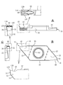
- A is the figure seen from the rake face side of the cutting edge
- B is the figure seen from the side flank face side
- C is the front flank face
- A is the figure seen from the side and the principal part enlarged view in each figure.
- FIG. A is an enlarged plan view of the cutting edge portion as viewed from the rake face side, and B is cut along a straight line that passes through the center of the front cutting edge in A and is pulled backward substantially perpendicular to the front cutting edge.
- FIG. A is a partially enlarged view of the front cutting edge as seen from the front flank side, and a further enlarged view of the recessed groove portion of the front cutting edge, B is a sectional view taken along line S1-S1 in FIG. 4, and C is S2-S2 in FIG. Sectional drawing, D is a sectional view taken along line S3-S3 in FIG. FIG.
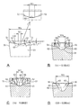
- FIG 5 is a diagram schematically illustrating a state in which the generated chips flow through the rake face and the cross section thereof changes, where A is the amount of chips generated immediately after being cut by the front cutting edge of FIG.
- FIGS. BD are cut end views for explaining the state of deformation of chips at each of the cross-sectional positions of FIGS.
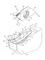
- the cutting insert 100 of this example is used for grooving with a predetermined width, or for cutting off (cutting) a predetermined small-diameter round bar.
- the entire cutting insert 100 has a substantially parallelogram-like plate shape.
- a cutting edge 10 is provided at two acute corners facing each other across a clamp screw hole 105 provided in the center.
- Each of the cutting edges 10 is formed such that one surface of a parallelogram (plate) is thinly cut into a substantially triangular shape including its acute corners (see FIG. 1A and the like). That is, the triangular thin plate portion 22 constitutes the cutting edge 10 that is responsible for grooving or parting off.
- the material of the cutting insert of the present invention is “Cemented carbide”, specifically, “Coated cemented carbide”. However, the material is not limited to this. As other materials, known materials such as “cermet” and “ceramic” can be used.
- the cutting insert 100 of this example is arranged so that a portion near the corner of the sharp corner of the surface 30 along the long side of the parallelogram plate forms a rake surface 40. Details of the shape and structure of the rake face 40 will be described later. And it cut
- a ridge line part where the tip of the rake face 40 (a part near the sharp corner) and the front flank 33 forms the front cutting edge 110.
- the front cutting edge 110 forms a straight line before the formation of a groove to be described later, and when viewed from the rake face 40 side (see FIG. 4 and the like), the side cutting edges 120 extending rearward at both ends of the front cutting edge 110, respectively. have.
- the horizontal cutting edge 120 is spaced from the two horizontal cutting edges 120 when viewed from the rake face 40 side so that the part from the both ends of the front cutting edge 110 to the rear side does not rub the processing surface at the time of machining such as parting off. Has been made smaller.
- the side cutting edge 120 on each side is a workpiece (not shown) as viewed from the rake face 40 side at both ends of the front cutting edge 110 (straight line). It is provided so that it may be located inside two straight lines (not shown) drawn substantially perpendicularly toward the rear with respect to the rotation axis. Further, the side cutting edge 120 is composed of a ridge line intersecting the rake face 40 and the side flank face (the face of the triangular thin wall near the sharp corner of the parallelogram). It is formed so that an appropriate lateral clearance angle is sometimes given.
- a corner (corner) 112 formed by the front cutting edge 110 and the side cutting edge 120 in the rake face 40 is provided with a minute radius to prevent chipping.
- a part (rectangular part) surrounded by the front cutting edge 110 and the lateral cutting edges 120 on both sides is an intermediate part between the lateral cutting edges 120 on both sides from the center of the front cutting edge 110 to the rear.
- the shape of the rake face 40 in a cross section perpendicular to the straight line is substantially symmetric with respect to a straight line (not shown) drawn through the part. When viewed from the side of the flank 33, it is substantially bilaterally symmetrical with respect to a straight line (not shown) drawn perpendicularly to the front cutting edge 110 at the center of the front cutting edge 110.
- the rake face 40 extends rearward from the front cutting edge 110 so as to have a positive rake angle (for example, 15 degrees with respect to the long side of the parallelogram), and the rear (front-rear direction) thereof. It extends rearward through an arcuate curved surface that is concave so that the rake angle is negative (0 degree or negative rake angle) at an appropriate place (position P1 in FIG. 4).
- the rake face 40 is provided with a breaker wall 43 that continues to the curved surface and is inclined behind the curved face, for example, rising at 45 degrees.
- the rake face 40 has a positive rake face that is inclined so as to form a lower position from the front cutting edge 110 toward the rear so that a positive rake angle can be obtained.
- a breaker wall 43 that rises in an inclined manner behind the rear end of the surface (position P1 in FIG. 4) is provided.
- the front-rear range from the front cutting edge 110 toward the rear to the position P1 in FIG. 4 forms a positive rake face.
- the positive rake face has an arcuate curved surface that is recessed from the front cutting edge 110 toward the rear, and in the vicinity of the rear end position (position P1 in FIG. 4).
- a part of the curved surface is formed so as to form a leading end side of the breaker wall 43, that is, a rising base. Further, the upper end 45 of the breaker wall 43 is set to be slightly higher than the height of the front cutting edge 110, and is slightly lower than the long side of the parallelogram forming the cutting insert 100 with respect to the surface 30 along the long side. A surface extending backward with an inclination of about 3 degrees is formed, and this surface is a substantially flat surface 37.
- each horizontal cutting edge 120 including the front cutting edge 110 is lowered from the horizontal cutting edge 120 toward the central part sandwiched between both horizontal cutting edges 120.
- An inclined surface that is inclined in this manner is formed.
- the inclined surface on each side may be composed of one inclination, but in this example, each of the lateral cutting edges 120 faces a central portion sandwiched between the lateral cutting edges 120 and has a relatively small angle ⁇ 1 (for example, A first inclined surface 51 that inclines so as to form a lower position at 5 degrees with respect to the straight front cutting edge 110, and an angle ⁇ 2 (for example, a straight front cutting edge that is larger than this) following the first inclined surface.
- ⁇ 1 for example, A first inclined surface 51 that inclines so as to form a lower position at 5 degrees with respect to the straight front cutting edge 110, and an angle ⁇ 2 (for example, a straight front cutting edge that is larger than this) following the first inclined surface.
- the second inclined surface 52 is inclined so as to form a lower position at 12 degrees with respect to 110 (see FIG. 5).
- the inclined surface formed by the two first inclined surfaces 51 and the second inclined surface 52 is formed between the front and rear from the tip of the horizontal cutting edge 120 including the front cutting edge 110 to the upper end 45 of the breaker wall 43.
- the first inclined surface 51 extends in a strip shape along each horizontal cutting edge 120, and the width thereof is set to be substantially constant afterwards when the horizontal cutting edge 120 has no back rake.
- the width of the first inclined surface 51 on each side cutting edge 120 side is set to 1/10 to 1/5 of the cutting edge length of the front cutting edge 110 (the dimension between the tips of the side cutting edges 120).
- a concave groove 60 which is lower than both inclined faces is formed in a central portion sandwiched between both inclined faces (the first inclined face 51 and the second inclined face 52 on each side). , Extending in the front-rear direction including the front cutting edge 110, and formed in a shape that cuts behind the upper end 45 of the breaker wall 43, that is, into a flat surface 37 provided behind the upper end 45 of the breaker wall 43. Yes.
- the groove 60 has a semicircular arc shape in which the groove bottom side is concave or a V groove shape in which a portion near the groove bottom forms a semicircular arc shape (see FIG. 5 and the like).
- the width is provided so as to change in the front-rear direction.
- the front cutting edge 110 is provided with a front clearance angle, so that the inclined surface as described above is formed on the rake face 40 including the front cutting edge 110. Strictly speaking, the front cutting edge 110 when viewed from the surface 40 side is not a straight line, but the groove 60 is provided so as to be cut into the front cutting edge 110 as described above. The center of the front cutting edge 110 forms a slight but concave rearward when viewed from the rake face 40 side. However, since the depth of the groove formed by being cut between the inclined surfaces at the central portion of the front cutting edge 110 is very small as shown in FIG. There are also a few. The depth of the groove will be described later.
- the groove width is the width dimension between the groove edges on each side of the groove 60, that is, the groove wall (groove wall surface) 63 on each side and the inclined surface on each side (in this example, It is the width at the ridge line portion 65 where the second inclined surface 52) intersects.
- a minute (about 0.1 mm) radius (thread chamfering) is given to the intersecting ridge lines 65. That is, the groove 60 extending forward and backward is cut so as to continue to the center of the front cutting edge 110, and the groove width dimension W1 of the groove 60 in the front cutting edge 110 is shown in FIG. As shown, the groove width is gradually increased toward the rear, and then gradually decreased, and approximately the intermediate portion P2 between the front cutting edge 110 and the upper end 45 of the breaker wall 43 in the front-rear direction of the rake face 40 ( The narrowest part in the gradual reduction is shown at the line S2-S2 in FIG.
- the position P2 of the groove width dimension W2 which is the narrowest portion is formed so as to be gradually increased from the position P2 of the groove width dimension W2 which is the narrowest portion to the position P3 (the portion of the line S3-S3 in FIG. 4) of the upper end 45 of the breaker wall 43 facing backward.
- the change such as gradual increase is formed by a gentle curve as viewed from the rake face 40 side.
- the position P2 of the narrowest portion is set ahead of the position P3 of the upper end 45 of the breaker wall 43 in the front-rear direction of the rake face 40 and behind the rear end position P1 of the positive rake angle. ing. For this reason, the flow direction of the chips flowing backward from the front cutting edge 110 along the positive rake angle on the rake face 40 is changed from the downward direction to the horizontal or upward direction at the position P2 of the narrowest portion. It has come to be.
- the groove width dimension in the position of the front cutting edge 110 among the recessed grooves 60 is set to W1
- the groove width dimension in the position P2 of the narrowest part in the front-rear direction is set to W2
- the position of the upper end 45 of the breaker wall 43 When the groove width dimension at P3 is W3, the groove width dimensions at the respective positions, W1, W2, and W3, are formed so as to have a dimensional relationship of W1 ⁇ W2 ⁇ W3.
- W1 has a dimensional relationship of W1 ⁇ Wa / 2 when the length when viewed from the rake face 40 side of the front cutting edge 110 is Wa, but in this example, W1 is 1 of Wa. It is set to about / 5.
- W1 is about half of W2.
- W2 is set to about 1/3 of Wa.
- W3 is set to about 1 ⁇ 2 of Wa.
- the recessed groove 60 extending rearward is formed so as to cut behind the flat surface 37 provided behind the upper end 45 of the breaker wall 43, and the groove of the recessed groove 60 in the flat surface 37 is formed. The width gradually decreases toward the rear end 67 and ends.
- the groove width Wm at the maximum groove width portion in the middle which is the switching position where the groove width is gradually increased from the recessed groove 60 to the rear in the front cutting edge 110 and then gradually decreased. Is larger than the groove width dimensions W1 and W2, but smaller than W3.
- the portion having the groove width Wm is an intermediate portion between the position of the ridge groove width dimension W1 and the position P2 of the groove width dimension W2 (the position of the SS line in FIG. 4).
- the depth of the concave groove 60 may be constant until the breaker wall 43, but in this example, it is assumed that the depth changes as follows. That is, as shown in FIGS. 4 and 5, the depth of the concave groove 60 in this example is the rear from the position of the front cutting edge 110 at the tip as the groove depth from the lateral cutting edge 120. As it goes, it becomes deeper and becomes maximum (deepest) at the intermediate portion between the position of the groove width dimension W1 and the position P2 of the groove width dimension W2, and then gradually becomes shallower (position of the groove width dimension W2). Therefore, it is set to be gradually deeper to the vicinity of the position P3 corresponding to the upper end 45 of the breaker wall 43.
- the position where the maximum (deepest) depth is reached that is, the intermediate portion between the position of the groove width dimension W1 and the position of the groove width dimension W2 is rearward.
- the position corresponding to the position P3 of the upper end 45 of the breaker wall 43 is set to be slightly deeper and corresponds to the position P3 of the upper end 45 of the breaker wall 43 as shown in the drawing (see the sectional view in FIG. 4). It is made to become gradually shallower from the position where it goes to the rear.
- the groove depth at the deepest portion and the portion of the groove width dimension W2 is a dimension within a range of 1/5 to 2/3 with respect to the groove width dimension at each portion.
- Chips generated in the case of grooving or parting-off by turning using such a cutting insert 100 of this example are pressed toward the rake face 40 and the groove bottom side of the groove 60, and the groove width dimension is as described above. Since the flow is guided rearwardly along the concave groove 60 that changes as described above, it is wound and discharged in a mainspring shape without lateral deviation regardless of the difference in the thickness of the chips depending on the amount of feed. Thereby, it is prevented that a work material is damaged and the surface roughness of the cut end face is improved.
- the actual machining conditions are as follows.
- the work material is SUS304, a ⁇ 8 mm round bar, the cutting speed is 80 m / min, and the feed amount is in the range of 0.02 to 0.08 mm / rev. .
- the cutting insert 100 of this example When the cutting insert 100 of this example is cut into a work material with a predetermined feed amount, as shown in FIG. 6-A, it is generated as a chip K1 having a cross section along the shape of the front cutting edge 110, which is a rake face. It flows backward while being pressed onto 40. Based on the shape of the front cutting edge 110, the chip K1 generated at the start of cutting is generated such that the middle (center) portion in the width direction has a downward convex shape, and is directed rearward along the concave groove 60. It is guided and flows.
- production is considered to be substantially the same as the width Wa of the front cutting edge 110.
- groove 60 is designed so that the groove
- the portions near both sides of the chip or both sides are the ridge line portions 65 on both edges of the concave groove 60. And so on.
- the chips are subjected to a deforming action such that the portions near both ends in the cross section are pushed upward (folded).
- the chips are deformed into a cross section having a larger convex portion with the central portion in the width direction facing downward, and the width is further reduced.
- the groove width dimension W2 is set to be larger than the groove width dimension W1 of the front cutting edge 110, the ridge that continues from the downward convexity in the chips generated at the start of cutting is the narrowest portion (constricted part). , The guide action in the backward flow is also maintained.
- the chips that have passed through the narrowest portion flow backward through the concave groove 60 in which the groove width gradually increases toward the upper end 45 of the rear breaker wall 43.
- the chips K4 flow backward while being pressed against the ridges 65 on both edges of the groove 60 in a state where the chips K4 can sink toward the groove bottom of the groove 60, and therefore the upper end of the breaker wall 43 It flows without being laterally displaced up to 45, being guided by the concave groove 60 (see FIG. 6-D).
- the chips K4 that have flowed rearward through the rake face 40 in this way are wound in a mainspring shape without lateral displacement, and are divided at an appropriate length.
- the change in the groove width is embodied as a gentle curve when viewed from the rake face side.
- the groove width is gradually increased and decreased. You may let them.
- the groove width dimensions, W1, W2, and W3 can be set to appropriate sizes according to the leading and trailing lengths of the rake face, the length of the front cutting edge, and the like as long as the dimensional relationship of W1 ⁇ W2 ⁇ W3 is satisfied.
- the position P2 of the narrowest narrow part (groove width dimension, W2) after the gradual increase is the size of the rake angle on the rake face, the rising state of the breaker wall, the front and rear length from the front cutting edge to the upper end of the breaker wall, May be set as appropriate according to processing conditions such as the amount of feed.
- the depth of the concave groove affects the deformation in the width direction of the chip together with the inclination angle of the inclined surface. This is the length of the front cutting edge, that is, in the width of the chip and turning.
- the cutting insert has a parallelogram shape, and is embodied in one having two cutting edges each having a cutting edge at the opposing acute angle corner.
- the shape of the cutting insert (main body) itself such as a cutting insert that is triangular and has cutting edges at three corners, or a so-called dogbone type that has a rectangular (rectangular) plate shape with cutting edges at both ends. It can be embodied in cutting inserts of various shapes.
- the groove width as viewed from the rake face side, and the groove width dimension W3 at the position of the narrowest part The groove width as viewed from the rake face side of the concave groove, and the groove width dimension Wa at the position of the upper end of the breaker wall Length when viewed from the rake face side of the blade
Landscapes
- Engineering & Computer Science (AREA)
- Mechanical Engineering (AREA)
- Cutting Tools, Boring Holders, And Turrets (AREA)
- Milling Processes (AREA)
Abstract
Description
すくい面は、ポジ状のすくい角が得られるように、前記前切れ刃から後方に向かって低位をなすように傾斜するポジ状すくい面を有すると共に、このポジ状すくい面の後端又は該後端より後方において傾斜状に立ち上がるブレーカ壁を備え、
前記すくい面のうち、前記前切れ刃を含む各横切れ刃の先後方向に沿う部位には、各横切れ刃から、両横切れ刃に挟まれる中央部位に向かって低位をなすように傾斜する傾斜面が形成されていると共に、前記両傾斜面に挟まれる中央部位には、該両傾斜面より低位をなす凹溝が、前記前切れ刃を含めて先後方向に延び、かつブレーカ壁の上端を越えて後方に切り込む形で形成されており、
かつ、該凹溝は、前記すくい面側から見た溝幅が、前記前切れ刃と前記ブレーカ壁の上端との先後間において、
該前切れ刃の位置から後方に向けて漸増させられた後で漸減させられ、前記ブレーカ壁の上端の位置より先方であって前記ポジ状のすくい角の後端位置である前記ポジ状すくい面の後端より後方においてその漸減における最狭小部をなし、この最狭小部の位置から後方に向かうブレーカ壁の上端の位置まで漸増させられるように形成され、
前記前切れ刃の位置における溝幅寸法をW1とし、前記最狭小部の位置における溝幅寸法をW2とし、前記ブレーカ壁の上端の位置における溝幅寸法をW3としたとき、この各位置における溝幅寸法、W1、W2、W3が、
W1<W2<W3の寸法関係となるように形成されていることを特徴とする。
請求項3に記載の発明は、前記前切れ刃のすくい面側から見たときの長さを、Waとしたとき、上記W1とWaとが、W1≦Wa/2の寸法関係にあることを特徴とする請求項1又は2のいずれか1項に記載の切削インサートである。
請求項5に記載の発明は、前記切削インサートが、溝入れ用又は突っ切り用の切削インサートであることを特徴とする請求項1~4のいずれか1項に記載の切削インサートである。
43 ブレーカ壁
45 ブレーカ壁の上端
51,52 傾斜面(第1傾斜面、第2傾斜面)
60 凹溝
100 切削インサート
112 前切れ刃と横切れ刃とのなすコーナ
110 前切れ刃
120 横切れ刃
P1 ポジ状のすくい角の後端位置(ポジ状のすくい面の後端)
P2 ポジ状のすくい角の後端位置より後方位置の漸減における最狭小部の位置
W1 凹溝のすくい面側から見た溝幅であって、前切れ刃の位置における溝幅寸法
W2 凹溝のすくい面側から見た溝幅であって、最狭小部の位置における溝幅寸法
W3 凹溝のすくい面側から見た溝幅であって、ブレーカ壁の上端の位置における溝幅寸法
Wa 前切れ刃のすくい面側から見たときの長さ
Claims (5)
- 前切れ刃と、前記前切れ刃の両端においてそれぞれ後方に延びる横切れ刃を有する切削インサートであって、
すくい面は、ポジ状のすくい角が得られるように、前記前切れ刃から後方に向かって低位をなすように傾斜するポジ状すくい面を有すると共に、このポジ状すくい面の後端又は該後端より後方において傾斜状に立ち上がるブレーカ壁を備え、
前記すくい面のうち、前記前切れ刃を含む各横切れ刃の先後方向に沿う部位には、各横切れ刃から、両横切れ刃に挟まれる中央部位に向かって低位をなすように傾斜する傾斜面が形成されていると共に、前記両傾斜面に挟まれる中央部位には、該両傾斜面より低位をなす凹溝が、前記前切れ刃を含めて先後方向に延び、かつブレーカ壁の上端を越えて後方に切り込む形で形成されており、
かつ、該凹溝は、前記すくい面側から見た溝幅が、前記前切れ刃と前記ブレーカ壁の上端との先後間において、
該前切れ刃の位置から後方に向けて漸増させられた後で漸減させられ、前記ブレーカ壁の上端の位置より先方であって前記ポジ状のすくい角の後端位置である前記ポジ状すくい面の後端より後方においてその漸減における最狭小部をなし、この最狭小部の位置から後方に向かうブレーカ壁の上端の位置まで漸増させられるように形成され、
前記前切れ刃の位置における溝幅寸法をW1とし、前記最狭小部の位置における溝幅寸法をW2とし、前記ブレーカ壁の上端の位置における溝幅寸法をW3としたとき、この各位置における溝幅寸法、W1、W2、W3が、
W1<W2<W3の寸法関係となるように形成されていることを特徴とする切削インサート。 - 前記傾斜面が、それぞれ、各横切れ刃から前記中央部位に向かい、相対的に、小さい角度α1で低位をなすように傾斜する第1傾斜面と、該第1傾斜面に続き、これより大きい角度α2で低位をなすように傾斜する第2傾斜面とを有していることを特徴とする請求項1に記載の切削インサート。
- 前記前切れ刃のすくい面側から見たときの長さを、Waとしたとき、上記W1とWaとが、W1≦Wa/2の寸法関係にあることを特徴とする請求項1又は2のいずれか1項に記載の切削インサート。
- 前記すくい面側から見たときにおける前記前切れ刃と前記横切れ刃とのなす各コーナに、アールが付与されていることを特徴とする請求項1~3のいずれか1項に記載の切削インサート。
- 前記切削インサートが、溝入れ用又は突っ切り用の切削インサートであることを特徴とする請求項1~4のいずれか1項に記載の切削インサート。
Priority Applications (4)
| Application Number | Priority Date | Filing Date | Title |
|---|---|---|---|
| KR1020177004927A KR102003617B1 (ko) | 2014-10-28 | 2015-10-16 | 절삭 인서트 |
| US15/505,146 US10195672B2 (en) | 2014-10-28 | 2015-10-16 | Cutting insert |
| EP15855707.4A EP3213843B1 (en) | 2014-10-28 | 2015-10-16 | Cutting insert |
| CN201580038523.8A CN106536103B (zh) | 2014-10-28 | 2015-10-16 | 切削镶刀 |
Applications Claiming Priority (2)
| Application Number | Priority Date | Filing Date | Title |
|---|---|---|---|
| JP2014-219067 | 2014-10-28 | ||
| JP2014219067A JP6186335B2 (ja) | 2014-10-28 | 2014-10-28 | 切削インサート |
Publications (1)
| Publication Number | Publication Date |
|---|---|
| WO2016067547A1 true WO2016067547A1 (ja) | 2016-05-06 |
Family
ID=55856914
Family Applications (1)
| Application Number | Title | Priority Date | Filing Date |
|---|---|---|---|
| PCT/JP2015/005241 WO2016067547A1 (ja) | 2014-10-28 | 2015-10-16 | 切削インサート |
Country Status (6)
| Country | Link |
|---|---|
| US (1) | US10195672B2 (ja) |
| EP (1) | EP3213843B1 (ja) |
| JP (1) | JP6186335B2 (ja) |
| KR (1) | KR102003617B1 (ja) |
| CN (1) | CN106536103B (ja) |
| WO (1) | WO2016067547A1 (ja) |
Cited By (1)
| Publication number | Priority date | Publication date | Assignee | Title |
|---|---|---|---|---|
| JP6976522B1 (ja) * | 2021-02-18 | 2021-12-08 | 株式会社タンガロイ | 切削工具及び切削インサート |
Families Citing this family (9)
| Publication number | Priority date | Publication date | Assignee | Title |
|---|---|---|---|---|
| JP6776199B2 (ja) * | 2017-07-18 | 2020-10-28 | 日本特殊陶業株式会社 | 切削インサート |
| JP6315867B1 (ja) * | 2017-10-16 | 2018-04-25 | 株式会社谷テック | 金属切断用丸鋸 |
| DE102018130788A1 (de) * | 2018-12-04 | 2020-06-04 | Hartmetall-Werkzeugfabrik Paul Horn Gmbh | Schneidplatte und Werkzeug zur spanenden Bearbeitung eines Werkstücks |
| JP6936975B2 (ja) * | 2018-12-28 | 2021-09-22 | 株式会社タンガロイ | 切削インサート及び切削工具 |
| CN113518679B (zh) * | 2019-03-13 | 2023-12-22 | 京瓷株式会社 | 切削刀片、切削刀具以及切削加工物的制造方法 |
| KR102191172B1 (ko) * | 2019-05-21 | 2020-12-15 | 한국야금 주식회사 | 절삭인서트 및 절삭공구 어셈블리 |
| JP6733784B1 (ja) * | 2019-06-28 | 2020-08-05 | 株式会社タンガロイ | 切削インサート及び切削工具 |
| CN111001835A (zh) * | 2019-12-25 | 2020-04-14 | 厦门金鹭特种合金有限公司 | 一种带断屑槽的超硬切槽刀具 |
| JP6979179B1 (ja) * | 2021-06-25 | 2021-12-08 | 株式会社タンガロイ | 切削インサート |
Citations (5)
| Publication number | Priority date | Publication date | Assignee | Title |
|---|---|---|---|---|
| JP2008272924A (ja) * | 2007-03-30 | 2008-11-13 | Mitsubishi Materials Corp | 切削インサート |
| JP2010099815A (ja) * | 2008-10-27 | 2010-05-06 | Mitsubishi Materials Corp | 切削インサート |
| WO2011093333A1 (ja) * | 2010-01-29 | 2011-08-04 | 京セラ株式会社 | 切削インサートおよび切削工具、ならびにそれらを用いた被削材の切削方法 |
| WO2011149091A1 (ja) * | 2010-05-27 | 2011-12-01 | 京セラ株式会社 | 切削インサートおよび切削工具、ならびにそれらを用いた切削加工物の製造方法 |
| WO2012043629A1 (ja) * | 2010-09-29 | 2012-04-05 | 京セラ株式会社 | 切削インサートおよび切削工具、並びにそれらを用いた切削加工物の製造方法 |
Family Cites Families (15)
| Publication number | Priority date | Publication date | Assignee | Title |
|---|---|---|---|---|
| SE454060B (sv) * | 1986-08-15 | 1988-03-28 | Sandvik Ab | Spanavskiljande verktyg |
| SE504314C2 (sv) * | 1992-04-28 | 1997-01-13 | Sandvik Ab | Skärförsett verktyg för avstickning eller liknande svarvningsoperationer samt underläggselement för skär till dylika verktyg |
| SE505488C2 (sv) * | 1992-04-28 | 1997-09-08 | Sandvik Ab | Verktyg för avstickning eller liknande operationer |
| SE512094C2 (sv) * | 1998-05-22 | 2000-01-24 | Sandvik Ab | Skär för spårstickning |
| AU2003301264A1 (en) * | 2002-10-18 | 2004-05-04 | Manchester Tool Company | Tool holder and metal cutting insert with chip breaking surfaces |
| US20080240874A1 (en) | 2007-03-30 | 2008-10-02 | Mitsubishi Materials Corporation | Cutting insert |
| EP1980348B1 (en) * | 2007-03-30 | 2012-03-07 | Mitsubishi Materials Corporation | Cutting insert |
| CN101274371A (zh) * | 2007-03-30 | 2008-10-01 | 三菱麻铁里亚尔株式会社 | 切削刀片 |
| JP5092865B2 (ja) * | 2008-04-17 | 2012-12-05 | 株式会社タンガロイ | スローアウェイチップ |
| JP5332504B2 (ja) | 2008-10-27 | 2013-11-06 | 三菱マテリアル株式会社 | 切削インサート |
| CN102596459B (zh) * | 2009-10-29 | 2015-07-15 | 京瓷株式会社 | 切削镶刀及切削工具、以及使用该切削工具的切削加工物的制造方法 |
| JP5459598B2 (ja) | 2009-11-09 | 2014-04-02 | 三菱マテリアル株式会社 | 切削インサート |
| IL208826A (en) * | 2010-10-20 | 2016-02-29 | Iscar Ltd | Cutting tools and cutting tool for him |
| DE102012111576B4 (de) * | 2012-11-29 | 2022-05-25 | Kennametal Inc. | Schneideinsatz mit Kühlmittelkanal und Schneidwerkzeug mit einem Werkzeughalter und einem solchen Schneideinsatz |
| US9314851B2 (en) * | 2013-05-21 | 2016-04-19 | Iscar, Ltd. | Cutting insert having a rearwardly offset cutting edge and cutting tool |
-
2014
- 2014-10-28 JP JP2014219067A patent/JP6186335B2/ja active Active
-
2015
- 2015-10-16 KR KR1020177004927A patent/KR102003617B1/ko active IP Right Grant
- 2015-10-16 WO PCT/JP2015/005241 patent/WO2016067547A1/ja active Application Filing
- 2015-10-16 US US15/505,146 patent/US10195672B2/en active Active
- 2015-10-16 CN CN201580038523.8A patent/CN106536103B/zh active Active
- 2015-10-16 EP EP15855707.4A patent/EP3213843B1/en active Active
Patent Citations (5)
| Publication number | Priority date | Publication date | Assignee | Title |
|---|---|---|---|---|
| JP2008272924A (ja) * | 2007-03-30 | 2008-11-13 | Mitsubishi Materials Corp | 切削インサート |
| JP2010099815A (ja) * | 2008-10-27 | 2010-05-06 | Mitsubishi Materials Corp | 切削インサート |
| WO2011093333A1 (ja) * | 2010-01-29 | 2011-08-04 | 京セラ株式会社 | 切削インサートおよび切削工具、ならびにそれらを用いた被削材の切削方法 |
| WO2011149091A1 (ja) * | 2010-05-27 | 2011-12-01 | 京セラ株式会社 | 切削インサートおよび切削工具、ならびにそれらを用いた切削加工物の製造方法 |
| WO2012043629A1 (ja) * | 2010-09-29 | 2012-04-05 | 京セラ株式会社 | 切削インサートおよび切削工具、並びにそれらを用いた切削加工物の製造方法 |
Non-Patent Citations (1)
| Title |
|---|
| See also references of EP3213843A4 * |
Cited By (5)
| Publication number | Priority date | Publication date | Assignee | Title |
|---|---|---|---|---|
| JP6976522B1 (ja) * | 2021-02-18 | 2021-12-08 | 株式会社タンガロイ | 切削工具及び切削インサート |
| JP2022126040A (ja) * | 2021-02-18 | 2022-08-30 | 株式会社タンガロイ | 切削工具及び切削インサート |
| CN114951721A (zh) * | 2021-02-18 | 2022-08-30 | 株式会社泰珂洛 | 切削工具以及切削刀片 |
| US11642726B2 (en) | 2021-02-18 | 2023-05-09 | Tungaloy Corporation | Cutting tool and cutting insert |
| CN114951721B (zh) * | 2021-02-18 | 2023-10-31 | 株式会社泰珂洛 | 切削工具以及切削刀片 |
Also Published As
| Publication number | Publication date |
|---|---|
| EP3213843A1 (en) | 2017-09-06 |
| KR20170033887A (ko) | 2017-03-27 |
| US20170266732A1 (en) | 2017-09-21 |
| EP3213843A4 (en) | 2018-07-18 |
| JP2016083733A (ja) | 2016-05-19 |
| CN106536103B (zh) | 2018-10-23 |
| EP3213843B1 (en) | 2022-11-30 |
| KR102003617B1 (ko) | 2019-07-24 |
| US10195672B2 (en) | 2019-02-05 |
| CN106536103A (zh) | 2017-03-22 |
| JP6186335B2 (ja) | 2017-08-23 |
Similar Documents
| Publication | Publication Date | Title |
|---|---|---|
| WO2016067547A1 (ja) | 切削インサート | |
| JP2016083733A5 (ja) | ||
| JP5438771B2 (ja) | 切削インサートおよび切削工具、並びにそれを用いた切削加工物の製造方法 | |
| US8137035B2 (en) | Cutting insert | |
| JP6611260B2 (ja) | ドリル | |
| JP6122487B2 (ja) | ドリルおよびそれを用いた切削加工物の製造方法 | |
| JP5895456B2 (ja) | 切削インサート | |
| EP1980348A2 (en) | Cutting insert | |
| JP6470307B2 (ja) | ドリル及びそれを用いた切削加工物の製造方法 | |
| WO2015064559A1 (ja) | 切削インサート及び切削工具、並びにそれらを用いた切削加工物の製造方法 | |
| JP6412022B2 (ja) | エンドミルおよび切削加工物の製造方法 | |
| US10220451B2 (en) | End mill and method for manufacturing machined product | |
| JP2007260901A (ja) | ばり取りツール用のばり取りカッタ | |
| JP5956705B1 (ja) | エンドミル | |
| JP2017202541A (ja) | ドリルリーマ | |
| JP2012030306A (ja) | ドリル及びそれを用いた穴加工方法 | |
| JP6499610B2 (ja) | 穴明け工具 | |
| JP5589425B2 (ja) | 溝入れ・突っ切り加工用切削インサート | |
| JP2005288613A (ja) | スローアウェイチップ | |
| JP2019018288A (ja) | 切削インサート | |
| KR101115657B1 (ko) | 홈 가공용 인서트 | |
| JP2008307621A (ja) | 荒切削用クリスマスカッタ | |
| JP2007245278A (ja) | エンドミル | |
| CN215587886U (zh) | 切削刀片及切削工具 | |
| JP2015051475A (ja) | 切削インサート及び切削工具 |
Legal Events
| Date | Code | Title | Description |
|---|---|---|---|
| 121 | Ep: the epo has been informed by wipo that ep was designated in this application |
Ref document number: 15855707 Country of ref document: EP Kind code of ref document: A1 |
|
| WWE | Wipo information: entry into national phase |
Ref document number: 15505146 Country of ref document: US |
|
| ENP | Entry into the national phase |
Ref document number: 20177004927 Country of ref document: KR Kind code of ref document: A |
|
| REEP | Request for entry into the european phase |
Ref document number: 2015855707 Country of ref document: EP |
|
| NENP | Non-entry into the national phase |
Ref country code: DE |