WO2016052539A1 - 家庭用薄葉紙収納容器 - Google Patents
家庭用薄葉紙収納容器 Download PDFInfo
- Publication number
- WO2016052539A1 WO2016052539A1 PCT/JP2015/077579 JP2015077579W WO2016052539A1 WO 2016052539 A1 WO2016052539 A1 WO 2016052539A1 JP 2015077579 W JP2015077579 W JP 2015077579W WO 2016052539 A1 WO2016052539 A1 WO 2016052539A1
- Authority
- WO
- WIPO (PCT)
- Prior art keywords
- thin paper
- household thin
- upper lid
- storage container
- frame member
- Prior art date
Links
- 229920001971 elastomer Polymers 0.000 claims description 15
- 239000000806 elastomer Substances 0.000 claims description 13
- 230000005484 gravity Effects 0.000 claims description 13
- 230000002093 peripheral effect Effects 0.000 claims description 13
- 229920005989 resin Polymers 0.000 claims description 11
- 239000011347 resin Substances 0.000 claims description 11
- 230000010363 phase shift Effects 0.000 claims description 3
- 239000000123 paper Substances 0.000 description 144
- 238000012856 packing Methods 0.000 description 73
- 210000000078 claw Anatomy 0.000 description 18
- 239000011101 paper laminate Substances 0.000 description 16
- 230000000052 comparative effect Effects 0.000 description 15
- 239000000463 material Substances 0.000 description 14
- 239000004698 Polyethylene Substances 0.000 description 8
- 238000012360 testing method Methods 0.000 description 6
- 238000004519 manufacturing process Methods 0.000 description 5
- -1 polypropylene Polymers 0.000 description 5
- 230000035939 shock Effects 0.000 description 5
- 239000007779 soft material Substances 0.000 description 5
- 239000000126 substance Substances 0.000 description 5
- 239000004743 Polypropylene Substances 0.000 description 4
- PPBRXRYQALVLMV-UHFFFAOYSA-N Styrene Chemical compound C=CC1=CC=CC=C1 PPBRXRYQALVLMV-UHFFFAOYSA-N 0.000 description 4
- 238000011156 evaluation Methods 0.000 description 4
- 238000000605 extraction Methods 0.000 description 4
- 238000000034 method Methods 0.000 description 4
- 238000012986 modification Methods 0.000 description 4
- 230000004048 modification Effects 0.000 description 4
- 239000002861 polymer material Substances 0.000 description 4
- 238000010998 test method Methods 0.000 description 4
- 230000000630 rising effect Effects 0.000 description 3
- 239000004677 Nylon Substances 0.000 description 2
- BZHJMEDXRYGGRV-UHFFFAOYSA-N Vinyl chloride Chemical compound ClC=C BZHJMEDXRYGGRV-UHFFFAOYSA-N 0.000 description 2
- XECAHXYUAAWDEL-UHFFFAOYSA-N acrylonitrile butadiene styrene Chemical compound C=CC=C.C=CC#N.C=CC1=CC=CC=C1 XECAHXYUAAWDEL-UHFFFAOYSA-N 0.000 description 2
- 239000004676 acrylonitrile butadiene styrene Substances 0.000 description 2
- 229920000122 acrylonitrile butadiene styrene Polymers 0.000 description 2
- 150000001336 alkenes Chemical class 0.000 description 2
- 238000005452 bending Methods 0.000 description 2
- 238000001704 evaporation Methods 0.000 description 2
- 230000008020 evaporation Effects 0.000 description 2
- 230000002401 inhibitory effect Effects 0.000 description 2
- 238000002347 injection Methods 0.000 description 2
- 239000007924 injection Substances 0.000 description 2
- 239000007788 liquid Substances 0.000 description 2
- 229920001684 low density polyethylene Polymers 0.000 description 2
- 239000004702 low-density polyethylene Substances 0.000 description 2
- 239000002184 metal Substances 0.000 description 2
- 229920001778 nylon Polymers 0.000 description 2
- JRZJOMJEPLMPRA-UHFFFAOYSA-N olefin Natural products CCCCCCCC=C JRZJOMJEPLMPRA-UHFFFAOYSA-N 0.000 description 2
- 238000004806 packaging method and process Methods 0.000 description 2
- 229920000728 polyester Polymers 0.000 description 2
- 229920000573 polyethylene Polymers 0.000 description 2
- 229920000139 polyethylene terephthalate Polymers 0.000 description 2
- 239000005020 polyethylene terephthalate Substances 0.000 description 2
- 229920001155 polypropylene Polymers 0.000 description 2
- 229920002635 polyurethane Polymers 0.000 description 2
- 239000004814 polyurethane Substances 0.000 description 2
- 239000004800 polyvinyl chloride Substances 0.000 description 2
- 229920000915 polyvinyl chloride Polymers 0.000 description 2
- 229920002379 silicone rubber Polymers 0.000 description 2
- 239000004945 silicone rubber Substances 0.000 description 2
- 239000012748 slip agent Substances 0.000 description 2
- 229920002725 thermoplastic elastomer Polymers 0.000 description 2
- 230000007704 transition Effects 0.000 description 2
- LFQSCWFLJHTTHZ-UHFFFAOYSA-N Ethanol Chemical compound CCO LFQSCWFLJHTTHZ-UHFFFAOYSA-N 0.000 description 1
- 238000013459 approach Methods 0.000 description 1
- 230000003796 beauty Effects 0.000 description 1
- 238000000071 blow moulding Methods 0.000 description 1
- 230000008859 change Effects 0.000 description 1
- 230000006835 compression Effects 0.000 description 1
- 238000007906 compression Methods 0.000 description 1
- 230000000994 depressogenic effect Effects 0.000 description 1
- 230000002349 favourable effect Effects 0.000 description 1
- 238000003780 insertion Methods 0.000 description 1
- 230000037431 insertion Effects 0.000 description 1
- 230000009191 jumping Effects 0.000 description 1
- 230000007246 mechanism Effects 0.000 description 1
- 239000008155 medical solution Substances 0.000 description 1
- 239000007769 metal material Substances 0.000 description 1
- 239000000203 mixture Substances 0.000 description 1
- 229920003023 plastic Polymers 0.000 description 1
- 239000004033 plastic Substances 0.000 description 1
- 238000007789 sealing Methods 0.000 description 1
- 239000000243 solution Substances 0.000 description 1
- 230000001629 suppression Effects 0.000 description 1
- 229920005992 thermoplastic resin Polymers 0.000 description 1
Images

Classifications
-
- B—PERFORMING OPERATIONS; TRANSPORTING
- B65—CONVEYING; PACKING; STORING; HANDLING THIN OR FILAMENTARY MATERIAL
- B65D—CONTAINERS FOR STORAGE OR TRANSPORT OF ARTICLES OR MATERIALS, e.g. BAGS, BARRELS, BOTTLES, BOXES, CANS, CARTONS, CRATES, DRUMS, JARS, TANKS, HOPPERS, FORWARDING CONTAINERS; ACCESSORIES, CLOSURES, OR FITTINGS THEREFOR; PACKAGING ELEMENTS; PACKAGES
- B65D83/00—Containers or packages with special means for dispensing contents
- B65D83/08—Containers or packages with special means for dispensing contents for dispensing thin flat articles in succession
- B65D83/0805—Containers or packages with special means for dispensing contents for dispensing thin flat articles in succession through an aperture in a wall
- B65D83/0811—Containers or packages with special means for dispensing contents for dispensing thin flat articles in succession through an aperture in a wall with means for assisting dispensing
- B65D83/0835—Containers or packages with special means for dispensing contents for dispensing thin flat articles in succession through an aperture in a wall with means for assisting dispensing the articles being pulled out of the container
-
- A—HUMAN NECESSITIES
- A47—FURNITURE; DOMESTIC ARTICLES OR APPLIANCES; COFFEE MILLS; SPICE MILLS; SUCTION CLEANERS IN GENERAL
- A47K—SANITARY EQUIPMENT NOT OTHERWISE PROVIDED FOR; TOILET ACCESSORIES
- A47K10/00—Body-drying implements; Toilet paper; Holders therefor
- A47K10/24—Towel dispensers, e.g. for piled-up or folded textile towels; Toilet paper dispensers; Dispensers for piled-up or folded textile towels provided or not with devices for taking-up soiled towels as far as not mechanically driven
- A47K10/32—Dispensers for paper towels or toilet paper
- A47K10/42—Dispensers for paper towels or toilet paper dispensing from a store of single sheets, e.g. stacked
- A47K10/421—Dispensers for paper towels or toilet paper dispensing from a store of single sheets, e.g. stacked dispensing from the top of the dispenser
-
- A—HUMAN NECESSITIES
- A47—FURNITURE; DOMESTIC ARTICLES OR APPLIANCES; COFFEE MILLS; SPICE MILLS; SUCTION CLEANERS IN GENERAL
- A47K—SANITARY EQUIPMENT NOT OTHERWISE PROVIDED FOR; TOILET ACCESSORIES
- A47K10/00—Body-drying implements; Toilet paper; Holders therefor
- A47K10/16—Paper towels; Toilet paper; Holders therefor
- A47K10/18—Holders; Receptacles
- A47K10/20—Holders; Receptacles for piled sheets
-
- A—HUMAN NECESSITIES
- A47—FURNITURE; DOMESTIC ARTICLES OR APPLIANCES; COFFEE MILLS; SPICE MILLS; SUCTION CLEANERS IN GENERAL
- A47K—SANITARY EQUIPMENT NOT OTHERWISE PROVIDED FOR; TOILET ACCESSORIES
- A47K10/00—Body-drying implements; Toilet paper; Holders therefor
- A47K10/24—Towel dispensers, e.g. for piled-up or folded textile towels; Toilet paper dispensers; Dispensers for piled-up or folded textile towels provided or not with devices for taking-up soiled towels as far as not mechanically driven
- A47K10/32—Dispensers for paper towels or toilet paper
- A47K10/42—Dispensers for paper towels or toilet paper dispensing from a store of single sheets, e.g. stacked
-
- B—PERFORMING OPERATIONS; TRANSPORTING
- B65—CONVEYING; PACKING; STORING; HANDLING THIN OR FILAMENTARY MATERIAL
- B65D—CONTAINERS FOR STORAGE OR TRANSPORT OF ARTICLES OR MATERIALS, e.g. BAGS, BARRELS, BOTTLES, BOXES, CANS, CARTONS, CRATES, DRUMS, JARS, TANKS, HOPPERS, FORWARDING CONTAINERS; ACCESSORIES, CLOSURES, OR FITTINGS THEREFOR; PACKAGING ELEMENTS; PACKAGES
- B65D83/00—Containers or packages with special means for dispensing contents
- B65D83/08—Containers or packages with special means for dispensing contents for dispensing thin flat articles in succession
- B65D83/0894—Containers or packages with special means for dispensing contents for dispensing thin flat articles in succession the articles being positioned relative to one another or to the container in a special way, e.g. for facilitating dispensing, without additional support
-
- A—HUMAN NECESSITIES
- A47—FURNITURE; DOMESTIC ARTICLES OR APPLIANCES; COFFEE MILLS; SPICE MILLS; SUCTION CLEANERS IN GENERAL
- A47K—SANITARY EQUIPMENT NOT OTHERWISE PROVIDED FOR; TOILET ACCESSORIES
- A47K10/00—Body-drying implements; Toilet paper; Holders therefor
- A47K10/24—Towel dispensers, e.g. for piled-up or folded textile towels; Toilet paper dispensers; Dispensers for piled-up or folded textile towels provided or not with devices for taking-up soiled towels as far as not mechanically driven
- A47K10/32—Dispensers for paper towels or toilet paper
- A47K2010/3266—Wet wipes
Definitions
- the present invention relates to a household thin paper storage container for storing household thin paper.
- An object of the present invention is to provide a household thin paper storage container that can suppress the amount of household thin paper popping out without inhibiting the removal of the household thin paper that has fallen below the frame member.
- a case body having an outlet on the top surface and storing household thin paper on the inside;
- a household thin paper storage container comprising a lid that opens and closes the outlet,
- a frame member mounted on the peripheral edge of the outlet;
- the frame member is formed of an elastic member,
- Each end portion of the frame member in the short side direction of the case body in the plan view is provided with a holding portion that extends in a direction to close the outlet,
- Each of the holding portions is arranged with a phase shift in a longitudinal direction of the case body at the tip thereof so as not to overlap with each other, and a Z-shaped cut is formed in the frame member.
- the invention according to claim 2 is the household thin paper storage container according to claim 1,
- the outlet is provided at a position deviated from the center of gravity of the household thin paper storage container itself when the lid is opened in plan view.
- An extension portion that extends in a direction to close the outlet is provided on the gravity center side of the frame member so as not to overlap the holding portion.
- the invention according to claim 3 is the thin paper storage container for home use according to claim 1 or 2,
- the household thin paper is folded and stored in the case body,
- the folding direction of the household thin paper is parallel to the longitudinal direction of the case body in plan view.
- the invention according to claim 4 is the household thin paper storage container according to any one of claims 1 to 3,
- the frame member is formed of an elastomer resin.
- the invention according to claim 5 is the household thin paper storage container according to any one of claims 1 to 4,
- the lid body is configured to open and close the outlet by sliding movement with respect to the case body.
- the present invention it is possible to suppress the pop-out amount of the household thin paper without inhibiting the removal of the household thin paper that has fallen below the frame member.
- FIG. 4 is a cross-sectional view taken along line IV-IV of the household thin paper storage container of FIG. 2.
- FIG. 5 is a cross-sectional view taken along the line VV of the household thin paper storage container of FIG. 3. It is a top view which shows case side packing.
- FIG. 6 is a plan view showing a case side packing of Comparative Example 2.
- FIG. 10 is a perspective view showing a case side packing of Comparative Example 2.
- FIG. 9 is a plan view showing a case side packing of Modification 1; It is a perspective view which shows the case side packing of the modification 1.
- FIG. 10 is a plan view showing a case side packing of Comparative Example 2.
- the structure of the household thin paper storage container of this embodiment is demonstrated.
- the longitudinal direction of the household thin paper storage container is the left-right direction
- the short side direction of the planar view is the front-rear direction
- the height direction is the vertical direction.
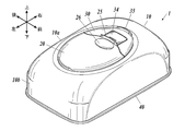
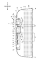
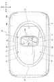
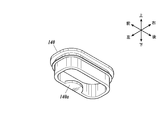
- the household thin paper storage container 1 is formed in a substantially rectangular shape with a rounded upper corner when viewed from the side in the front-rear direction with the upper lid 20 closed. It is configured so that wet type household thin paper P such as a wet sheet or wet tissue can be accommodated therein.
- the household thin paper storage container 1 may store dry type household thin paper P such as tissue paper, kitchen paper, and paper towel.
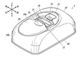
- the household thin paper storage container 1 has an outlet 11 for taking out the household thin paper P on the upper surface, and the household thin paper P is laminated on the lower surface.
- a container body 10 that has a bottom opening 12 for refilling the thin paper laminate Q and that houses the thin paper laminate Q in the inner storage space S, and is slidably provided on the upper surface of the container main body 10.
- an upper lid 20 as a lid body for opening and closing 11
- a chassis 30 for attaching the upper lid 20 to the container main body 10
- a bottom lid 40 for closing the bottom opening 12 of the container main body 10
- An urging member 50 that urges, and the like are configured.
- the container main body 10 and the chassis 30 have the outlet 11 on the upper surface, and function as a case body that houses the household thin paper P inside. That is, the case body includes a container body 10 and a chassis 30 that is fixed to the upper surface of the container body 10, and the upper lid 20 is attached to the chassis 30 of the case body.
- the container body 10, the upper lid 20, the chassis 30 and the bottom lid 40 are made of, for example, PP (polypropylene), PE (polyethylene), PVC (polyvinyl chloride), PET (polyethylene terephthalate), ABS (Acrylonitrile Butadiene Styrene), etc. It is formed from a thermoplastic resin.
- a tension coil spring (pull spring) is used as the urging member 50.
- the urging member 50 is not limited to this, and can be arbitrarily changed as long as the urging member 50 is an elastic member.
- a torsion spring or a compression coil spring may be used.
- the biasing member 50 may be an elastic member made of a metal material or an elastic member made of a polymer material. Examples of elastic members made of polymer materials include plastic elastic members, rubber such as silicone rubber, and thermoplastic elastomers such as styrene, olefin, vinyl chloride, polyester, polyurethane, and nylon elastomers.
- Examples include elastic members (soft materials) such as elastic members, and the shape thereof may be spring-like, plate-like, tube-like, or string-like, and can be arbitrarily changed as appropriate. is there.
- the urging member 50 is made of a polymer material, unlike the metal urging member, the urging member 50 is not rusted and can be used stably over a long period of time.
- the household thin paper P stored in the household thin paper storage container 1 is a wet type household thin paper P
- the metal biasing member 50 is used, the biasing member is caused by the chemical solution evaporated from the household thin paper P. Therefore, it is preferable to use a biasing member 50 made of a polymer material.
- the upper lid 20 opens and closes by sliding in the left-right direction (the longitudinal direction of the container body 10 in plan view). That is, the upper lid 20 is opened by sliding from the position in the closed state to one of the left and right directions (left direction in this embodiment), and the other in the left and right direction (this embodiment). In this case, it is closed by sliding to the right). Then, the left and right sides of the household thin paper storage container 1 (on the left side in the present embodiment) are moved to the left and right sides of the household thin paper storage container 1 by moving the upper lid 20 in the opening direction (left direction). It is configured to be heavier than the side (in the present embodiment, the right side).
- the outlet 11 is provided at a position shifted from the center of gravity of the household thin paper storage container 1 itself when the upper lid 20 is opened in a plan view (a position shifted to the right in the present embodiment).
- the center of gravity of the household thin paper storage container 1 itself when the upper lid 20 is open is referred to as “open center of gravity”.
- the thin paper laminate Q is, for example, a refill thin paper laminate in which a plurality of household thin papers P are laminated, and is formed on the case body (the container body 10 in this embodiment).
- the household thin paper P is stacked in an alternately folded state so that it can be continuously taken out from the outlet 11. That is, when the household thin paper P is pulled out from the outlet 11 to the outside of the case body, a so-called pop-up method in which the upper end of the next household thin paper P is pulled out from the storage space S to a position protruding from the outlet 11. It has become.
- the thin paper laminate Q may be included in the package T provided with an opening T1 for taking out the household thin paper P as in the present embodiment, or may not be included in the package T. good.
- the thin paper laminate Q is enclosed by a moisture-proof packaging T. Is preferred.
- the container body 10 includes an upper surface portion 10a that constitutes the upper surface of the container body 10, and a circumferential surface portion 10b that constitutes the front, rear, left and right circumferential surfaces of the container body 10.
- the lower surface of the container body 10 is a bottom opening 12 that has a substantially rectangular shape with a square shape in plan view.
- a space surrounded by the bottom lid 40 attached so as to close the bottom surface opening 12 and the upper surface portion 10a and the peripheral surface portion 10b of the container main body 10 is a storage space portion for storing the thin paper laminate Q. S.
- the container body 10 having an open bottom surface is used and the thin paper laminate Q is refilled from the bottom surface side of the container body 10.
- the present invention is not limited to this.
- the bottom surface is closed. It is also possible to use a container main body 10 having an open front / rear / right / left side and to refill the thin paper laminate Q from either the front / rear / right / left side of the container main body 10.
- the upper surface portion 10 a of the container body 10 is provided with a concave portion 13 that is depressed downward, and an outlet 11 is formed on the bottom surface portion 13 a of the concave portion 13.
- the take-out port 11 is an opening formed in a substantially rectangular shape with a corner in plan view for taking out the household thin paper P stored in the storage space S inside the container body 10.
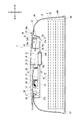
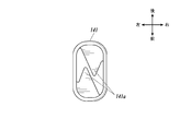
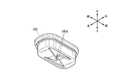
- the take-out port 11 is opened when the upper lid 20 is in an open state (see FIGS. 1B, 3, and 5).
- the household thin paper P is removed from the storage space S through the take-out port 11 one by one. It can be pulled out to the outside.
- the outlet 11 is closed when the upper lid 20 is in a closed state (see FIGS. 1A, 2 and 4).
- a case-side packing 14 is attached to the periphery of the outlet 11. That is, the case side packing 14 functions as a frame member attached to the peripheral edge of the outlet 11.
- a lid side packing 21 is also attached to the lower surface of the upper lid 20.
- the lid-side packing 21 is provided at a position corresponding to the case-side packing 14 in the closed state of the upper lid 20 on the lower surface of the upper lid 20.
- the case-side packing 14 and the lid-side packing 21 are such that the upper lid 20 is in the closed state. In such a case, they are in close contact with each other (see FIG. 4), so that the airtightness in the storage space S is maintained.
- the case side packing 14 and the lid side packing 21 function as an airtight means for sealing the gap between the peripheral edge of the outlet 11 and the upper lid 20.
- the case side packing 14 and the lid side packing 21 are made of thermoplastic elastomer such as rubber such as silicone rubber, styrene, olefin, vinyl chloride, polyester, polyurethane, nylon, and the like. It is made of a soft material (elastic member).
- the material for forming the lid side packing 21 is not limited to this.
- the lid side packing 21 may be formed of, for example, LDPE (Low Density Polyethylene) or a hard material such as PE (Polyethylene) or PP (Polypropylene). Further, the lid side packing 21 may be formed of the same material as the case side packing 14 or may be formed of a different material.
- the case-side packing 14 and the lid-side packing 21 are preferably formed of a chemical-resistant material, particularly when the household thin paper P stored in the household thin paper storage container 1 is a wet type.
- the case body packing 14 is provided on the container body 10 and the lid side packing 21 is provided on the upper lid 20, that is, the airtight means is provided on both the container body 10 and the upper lid 20.
- the airtight means may be provided only in the container body 10 as long as the gap between the peripheral edge of the outlet 11 and the upper lid 20 can be sealed by the airtight means.
- an airtight means may be provided in the chassis 30.
- the folding direction of the household thin paper P stored in the storage space S is parallel to the left-right direction (the longitudinal direction of the container body 10 in plan view). It has become.
- the longitudinal direction of the outlet 11 is orthogonal to the left-right direction (the longitudinal direction of the container body 10 in plan view). Accordingly, when the household thin paper P is pulled out from the outlet 11, the short portion of the case-side packing 14 attached to the outlet 11 (the household-use paper housed in the storage space portion S of the case-side packing 14 is used. (The portion parallel to the folding direction of the thin paper P) is in contact with the longitudinal portion of the case side packing 14 (the portion of the case side packing 14 perpendicular to the folding direction of the household thin paper P stored in the storage space S). To do.
- the lower end portion of the case side packing 14 protrudes toward the lower side (the thin paper laminate Q side stored in the storage space S) than the outlet 11. . Therefore, when the uppermost household thin paper P is taken out, the lower end portion of the case side packing 14 comes into contact with the uppermost household thin paper P or the next upper household thin paper P, and the uppermost household thin paper P or the like. Since resistance is given to the household thin paper P of the next layer, the protruding length of the household thin paper P of the next layer (the length of the portion protruding from the outlet 11) becomes longer than necessary, or a plurality of household It can suppress that the thin paper P is pulled out continuously. That is, the household thin paper P can be pressed by the case side packing 14 so that the household thin paper P does not jump out unnecessarily.
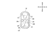
- the left side portion (the portion on the open center of gravity side) of the lower end portion of the case side packing 14 is directed inward (that is, in the direction of closing the outlet 11) as shown in FIGS. 6A and 6B, for example.
- An extension portion 14a extending in an arc shape is provided.
- a holding portion 14 b extending in the direction (front-rear direction) for closing the outlet 11 is provided at each end portion in the front-rear direction of the lower end portion of the case-side packing 14. Each is provided.
- incisions C1 to C4 are formed in the lower end portion of the case side packing 14, and the pair of holding portions 14b, 14b are in a state of being generally separated from the respective end portions in the left-right direction.
- each of the holding portions 14b and 14b is arranged by shifting the phase in the left-right direction at the tip thereof so as not to overlap each other.
- a Z-shaped cut is formed in the case side packing 14 by providing the pair of holding portions 14b and 14b.
- the Z-shape includes an inverted Z-shape obtained by inverting the letter “Z” left and right.
- a slip agent is added to at least one of the case side packing 14 and the lid side packing 21.
- the outlet 11 is shifted from the opening T1 of the package T in a plan view, and the center of the outlet 11 is packaged in a plan view. It is shifted to the right side (opposite to the open center of gravity) from the center of the opening T1 of the body T. That is, for example, as shown in FIG. 4, the distance L1 from the left end of the opening T1 (the left end on the longest axis of the opening T1) to the left end of the outlet 11 is the right end of the opening T1 (of the opening T1). The distance from the right end of the longest axis) to the right end of the outlet 11 is longer than the distance L2.
- the chassis 30 is fixed to the upper surface portion 10 a of the container main body 10 while being accommodated in the recess 13 of the container main body 10, and the upper lid 20 is attached to the container main body 10 via the chassis 30.
- the chassis 30 is placed on the bottom surface portion 13 a of the recess 13, and the frame portion 31 so as to be substantially flush with the frame portion 31 surrounding the outlet 11 and the closed upper lid 20.
- an upper wall portion 32 supported by.
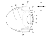
- a substantially elliptical plate-like member is configured in plan view.
- the upper lid 20 and the upper wall portion 32 have a curved shape so as to protrude downward in the front-rear direction (minor axis direction).
- the household thin paper storage container 1 includes two tension coil springs that are urging members 50.
- the frame portion 31 of the chassis 30 includes two fixed side engaging portions 33.
- the two fixed-side engaging portions 33 are a predetermined straight line (specifically, a straight line that passes through the movable-side engaging portion 22 in parallel with the left-right direction (major diameter direction)) in a state where the upper lid 20 and the chassis 30 are combined. ), And the distance between the upper lid 20 and the movable side engaging portion 22 in the closed state is larger than the distance between the upper lid 20 and the movable side engaging portion 22 in the opened state. It is provided in the frame part 31 so that it may become long.
- One end of the two urging members 50 is hooked on one of the two fixed-side engaging portions 33, and the other end of the two urging members 50 is 2
- the other fixed side engaging portion 33 is hooked on the other, and the other ends of the two biasing members 50 are hooked on the movable side engaging portion 22 provided on the upper lid 20.
- the urging member 50 urges the upper lid 20 in the open state when the upper lid 20 is closed.
- the force against the urging force of the urging member 50 is released, the upper lid 20 is pulled to the left side (that is, the side opposite to the upper wall portion 32) by the urging force of the urging member 50, and the take-out port 11 is opened.
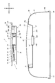
- the movable side engaging portion 22 is disposed above the fixed side engaging portion 33. Therefore, the urging member 50 is installed obliquely with respect to the height direction of the case body (the container main body 10 or the chassis 30). Specifically, the other end engaged with the movable side engaging portion 22 is fixed side. It is installed in a state of being arranged above one end engaged with the engaging portion 33. Therefore, the urging member 50 not only urges the upper lid 20 in the open state in the closed state of the upper lid 20, but also lowers the upper lid 20 downward (that is, the upper lid 20 as a case body (this embodiment).
- the pressure is also applied to the container body 10), so that the clearance between the peripheral edge of the outlet 11 and the upper lid 20 by the airtight means (in the case of the present embodiment, the case side packing 14 and the lid side packing 21). Is tightly sealed, and the airtightness of the storage space S is improved.
- a household thin paper storage container provided with a lid that opens and closes by rotating the open end up and down on the upper surface of a case body for storing household thin paper, the lid is opened.
- a biasing member such as a hinge formed by an elastomer or a torsion coil spring
- the urging member urges the lid in the open direction, i.e., urges the lid in the direction opposite to the closed state, and therefore has airtightness. It was difficult to make.
- a lid body (upper lid 20) that opens and closes by sliding in the left-right direction is provided, and the movable side engaging portion 22 is disposed above the fixed side engaging portion 33.
- the lid body (upper lid 20) is configured to be urged not only in the opening state but also in the direction in which the lid body is pressed. Therefore, the airtightness of the storage space S is improved.
- the household thin paper P stored in the household thin paper storage container 1 is a wet type household thin paper P as in the present embodiment, the evaporation of the chemical liquid impregnated in the household thin paper P is surely prevented. It can be done.
- the urging member 50 is composed of an elastic member
- the fixed side engaging portion 33 of the chassis 30 is provided on the case body (the chassis 30 in this embodiment) and engages with one end of the urging member 50.
- the movable side engaging portion 22 of the upper lid 20 functions as a movable point that is provided on the upper lid 20 and engages with the other end of the urging member 50.
- the biasing member 50, the fixed side engaging portion 33 of the chassis 30, and the movable side engaging portion 22 of the upper lid 20 function as a movable mechanism that slides and moves the upper lid 20 in the open state.
- the fixed side engaging portion 33 (fixed point) is provided in the chassis 30, but the present invention is not limited to this, and the fixed side engaging portion 33 (fixed point) is provided in the container body 10. Also good.
- the biasing member 50, the fixed side engaging portion 33 of the chassis 30, and the movable side engaging portion 22 of the upper lid 20 may be either in an open state or in a closed state.
- the upper lid 20 is covered with the upper lid 20 in the state of being placed in the recessed portion 13 even when it is in the middle of the transition from the open state to the closed state or in the middle of the transition from the closed state to the open state. Therefore, it cannot be visually recognized from the outside of the household thin paper storage container 1. That is, regardless of the state of the upper lid 20, the upper lid 20 shields the urging member 50, the fixed-side engaging portion 33 of the chassis 30, and the movable-side engaging portion 22 of the upper lid 20 from the outside. As a result, the beauty of the household thin paper storage container 1 is improved, and it is possible to prevent the biasing member 50, the fixed side engaging portion 33 of the chassis 30, and the movable side engaging portion 22 of the upper lid 20 from being touched. ing.
- the bottom surface portion 13a of the recess 13 is movable from the inside of the container body 10 (the storage space portion S side) so that the biasing member 50, the fixed-side engaging portion 33 of the chassis 30 and the upper lid 20 are not visible. Since the side engaging portion 22 is shielded, the biasing member 50, the fixed side engaging portion 33 of the chassis 30, and the movable side engaging portion 22 of the upper lid 20 can be prevented from being touched from the inside of the container body 10. It is like that.
- a claw portion 23 that protrudes downward is provided at the right end portion of the upper lid 20 (that is, the end portion on the upper wall portion 32 side).
- the chassis 30 is provided with a switch portion 34 having a part of the upper wall portion 32 as an operation surface 34a.
- the switch portion 34 is configured to be rotatable about a shaft portion 34b extending in the front-rear direction, and the claw portion 23 enters from the upper side to the left end side (that is, the upper lid 20 side). It has a claw receiving portion 34c to be engaged.
- the switch part 34 is urged
- the upper lid 20 When the upper lid 20 is in the open state, when a force against the urging force of the urging member 50 is applied to slide the upper lid 20 to the right side (that is, the upper wall portion 32 side), first, the upper lid 20 The claw portion 23 comes into contact with the claw receiving portion 34 c of the switch portion 34. When the upper lid 20 is further slid rightward, the claw receiving portion 34c is pushed by the claw portion 23, and a force against the urging force of the urging means of the switch portion 34 acts, and the claw receiving portion 34c moves downward. The switch portion 34 is rotated so as to move.
- the claw receiving portion 34c is returned to the original position by the urging force of the urging means of the switch portion 34.
- the switch portion 34 is rotated so that the operation surface 34a is substantially flush with the surface of the upper wall portion 32 so that the claw portion 23 and the claw receiving portion 34c are engaged. Thereby, the closed state of the upper lid 20 can be maintained.
- the claw portion 23 and the claw receiving portion 34c function as a locking means that locks the upper lid 20 against the biasing force of the biasing member 50 so that the upper lid 20 is in a closed state and can release the locking.
- the switch portion 34 that is pressed when releasing the locking by the locking means is provided in the chassis 30, but the present invention is not limited to this, and the switch portion 34 is provided in the container body 10. Also good.
- a part of the frame portion 31 of the chassis 30 is a rail portion 31a that guides the upper lid 20 to slide linearly.
- the frame portion 31 of the chassis 30 is extended along the left-right direction, and is aligned in the front-rear direction, and the right end portion of the rail portions 31 a, 31 a. (That is, the end portion on the direction side where the upper lid 20 is closed) and the support portion 31b that supports the upper wall portion 32 and the left end portions of the rail portions 31a and 31a (that is, the opened state of the upper lid 20) End portion on the direction side) connecting portion 31c for connecting each other.
- the upper lid 20 is provided with a slide portion 24 that is slidably engaged with the rail portion 31a.
- the sliding portion 24 is a hanging wall that hangs down from the lower surface of the upper lid 20 so that the lower surface of the sliding portion 24 contacts the upper surface of the corresponding rail portion 31a in a state where the upper lid 20 and the chassis 30 are combined. It is connected to the lower end of the part (not shown). Thereby, the upper cover 20 can be opened and closed smoothly and reliably.
- the rail portion 31 a for guiding the sliding movement of the upper lid 20 is provided in the chassis 30.
- the present invention is not limited to this, and the rail portion 31 a may be provided in the container body 10.
- the left end portion of the slide portion 24 absorbs an impact when the upper lid 20 is opened.
- a damper 24a is provided.
- the upper lid 20 is located at a position corresponding to the left end side (including the damper 24 a) of the slide portion 24 in the closed state of the upper lid 20 in the peripheral edge of the concave portion 13 of the container body 10.
- a horizontal hole portion 15 into which the slide portion 24 enters when shifting from the closed state to the open state is formed, and the damper 24a of the slide portion 24 contacts the container body 10 in the horizontal hole portion 15 when the upper lid 20 is open. It is configured as follows.
- the damper 24a is formed in an arcuate shape that curves from the inside to the outside so as to be convex to the left so that the shock can be absorbed by bending.
- the present invention is not limited to this. The shape of 24a can be arbitrarily changed as long as it can absorb an impact when the upper lid 20 is opened.
- the upper lid 20 is provided with a movable-side finger hooking portion 25 for hooking a finger when the upper lid 20 is closed.
- the upper lid 20 is formed by raising the right end portion of the upper lid 20 (that is, the end portion on the direction side where the upper lid 20 is closed) upward as the movable-side finger hook portion 25. Protruding portions are provided.
- the upper lid 20 has a concave portion formed by recessing the upper surface of the upper lid 20 downward as a finger placement portion 26 for placing a finger hung on the movable side finger hanging portion 25. Is provided.
- a non-moving side finger hook portion 35 is provided for hooking a finger when the upper lid 20 is closed.
- the chassis 30 is formed by raising the end portion of the chassis 30 (the right end portion of the upper wall portion 32 in the case of the present embodiment) upward as the immovable side finger hook portion 35. A protrusion is provided.
- the upper lid 20 when the upper lid 20 is closed by placing a finger on the left side of the movable side finger hooking portion 25 (that is, the side opposite to the non-moving side finger hooking portion 35), the right side (that is, the movable side finger hooking portion 35). Place the finger on the opposite side of the hook 25 and apply a leftward force (a force opposite to the force acting on the upper lid 20) to the container body 10 so that the container body 10 does not slip. Is configured to be fixed. Thereby, the upper cover 20 can be closed with one hand.
- the immovable side finger hook portion 35 is provided on the case body (in the case of this embodiment, the chassis 30) apart from the switch portion 34.
- the immovable side finger hook portion 35 is provided in the chassis 30, but the present invention is not limited to this, and the immovable side finger hook portion 35 may be provided in the container body 10.
- the lower surface of the upper lid 20 protrudes in a substantially inverted L shape when viewed from the side in the front-rear direction so that the front end faces the left side (that is, the direction side where the upper lid 20 is opened).
- a projecting piece 27 is provided. Further, for example, as shown in FIG. 7, in the peripheral edge of the concave portion 13 of the container body 10, the position corresponding to the tip end side (including a damper 27 a (described later)) of the protruding piece portion 27 in the closed state of the upper lid 20.
- the lateral hole portion 16 into which the protruding piece portion 27 enters is formed, and when the upper lid 20 is opened, the distal end side of the protruding piece portion 27 of the upper lid 20 is the container body. It is configured so that the vertical movement of the projecting piece 27 is restricted by entering the ten horizontal holes 16. Thereby, in the open state of the upper lid 20, it is possible to prevent the left end side of the upper lid 20 from moving upward and the upper lid 20 from rising up.
- a damper 27 a that absorbs an impact when the upper lid 20 is in an open state is provided at the tip of the projecting piece 27, and the upper lid 20 is opened.
- the damper 27 a of the projecting piece 27 is configured to come into contact with the container body 10 in the side hole 16. That is, the sliding movement of the upper lid 20 due to the urging force of the urging member 50 is also stopped when the projecting piece 27 collides with the container body 10, and the shock at the time of the collision is applied to the damper 27 a. Can be absorbed by.
- the damper 27a is formed in a bow shape curved from the upper side to the lower side so as to be convex to the left so that the impact can be absorbed by bending, but the present invention is not limited to this.
- the shape of the damper 27a can be arbitrarily changed as long as it can absorb an impact when the upper lid 20 is opened.
- the damper 27a is provided on the projecting piece 27 and the damper 24a is provided on the slide part 24. That is, the damper is provided on both the projecting piece 27 and the slide part 24.
- the present invention is not limited to this.
- the damper can absorb the shock when the upper lid 20 is opened (relax the shock), for example, the damper may be provided only on the projecting piece 27 or the slide part.
- a damper may be provided only at 24, or a damper may be provided at a portion other than the protruding piece portion 27 and the slide portion 24.
- the damper may be provided not on the upper lid 20 side but on the case body (container body 10 or chassis 30) side, or on both the upper lid 20 side and the case body side.
- the projecting piece portion 27 does not contact the container body 10 in the lateral hole portion 16 when the upper lid 20 is open.
- the slide portion 24 does not contact the container body 10 in the lateral hole portion 15 when the upper lid 20 is opened.
- the upper portion of the horizontal hole portion 15 into which the left end side of the slide portion 24 enters is configured to be blocked by the upper surface portion 10a.
- the present invention is not limited to this, and the horizontal hole portion 15 opens upward. Also good.
- the protruding piece 27 is provided to prevent the upper lid 20 from rising up, but the upper side of the horizontal hole portion 15 into which the left end side of the slide portion 24 enters is formed by the upper surface portion 10a as in the present embodiment. When it is blocked, the upper lid 20 can be prevented from rising by the slide portion 24.
- the left end side of the slide portion 24 of the upper lid 20 enters the horizontal hole portion 15 of the container body 10, and the vertical movement of the slide portion 24 is restricted. Since it is possible to prevent the upper lid 20 from getting up, the protruding piece 27 does not have to be provided.
- each part is produced by a manufacturing method such as blow molding, injection, blow injection, or the like.
- the urging member 50 and the upper lid 20 are assembled to the chassis 30 to form the assembly A.
- the assembly A is attached to the container body 10. Specifically, a plurality (five in the case of this embodiment) of fitting protrusions 36 provided on the lower surface of the chassis 30 and the fitting protrusions 36 on the bottom surface portion 13a of the recess 13 of the container body 10 correspond to the fitting protrusions 36.
- the assembly body A is attached to the container main body 10 by fitting the assembly A into the concave portion 13 of the container main body 10 from above the concave portion 13 so that the fitting hole portion 17 thus provided is fitted. That is, the urging member 50 and the upper lid 20 are attached to the container body 10 in a state of an assembly A that is assembled to the chassis 30 and integrally formed. Thereby, the effort which attaches the top cover 20, the biasing member 50, and the chassis 30 to the container main body 10 separately can be saved.
- the assembly A is fixed to the container body 10 by fitting the fitting projection 36 provided on the chassis 30 and the fitting hole 17 provided on the container body 10.
- the present invention is not limited to this.
- the assembly A may be fixed to the container body 10 with screws or the like.
- Example 1 The case side packing 14 (see FIG. 6 and the like) was used as a frame member attached to the peripheral edge of the outlet 11.
- a material for the case side packing 14 of Example 1 an elastomer resin having a hardness of 70 ° was used.
- Table 1 the mouse shape of the case side packing 14 is referred to as “A”.
- Case-side packing 14 (see FIG. 6 and the like) was used as the frame member.
- an elastomer resin having a hardness of 80 ° was used.
- Other conditions and test methods are the same as in Example 1.
- Case-side packing 14 (see FIG. 6 and the like) was used as the frame member.
- Other conditions and test methods are the same as in Example 1.
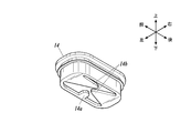
- As the frame member a case-shaped packing 140 (see FIG. 11) having a mouse shape different from the case-side packing 14 (see FIG. 6 and the like) was used.
- the case-side packing 140 is provided with an extending portion 140a that extends in an arc shape inward on the left side portion (the portion on the open center of gravity side) of the lower end portion. ing.
- the material of the case side packing 140 of Comparative Example 2 was PE, which is a hard material.
- the mouse shape of the case side packing 140 is referred to as “C”.
- Other conditions and test methods are the same as in Example 1.
- Example 1 In Comparative Example 2 (using the case side packing 140 with a large clearance at the extraction portion), the clearance at the extraction portion was large, and thus the result was that the amount of protrusion was large.
- Example 2 In Example 1 (uses the case side packing 14 with a hardness of 80 °) and Example 2 (uses the case side packing 14 with a hardness of 70 °), the gap at the take-out portion is small, so the pop-out amount is small. Results were obtained.
- Example 3 uses case side packing 14 having a hardness of 90 °
- Comparative Example 1 uses case side packing formed of PE, which is a hard material
- the gap at the take-out portion is small and the frame member is Since it was hard, the result was that the amount of popping out was very small.
- Example 3 good results were obtained for all items. Moreover, in Example 1 and Example 2, although it was inferior to Example 3 in the item of "the amount of popping out of household thin paper P", the favorable result was obtained. On the other hand, in Comparative Example 1, there was a problem in the item “easy to put out and put in fingers”. Further, in Comparative Example 2, there was a problem in both items of “amount of popping out household thin paper P” and “easy to put out and put in fingers”.
- case side packing 14 formed of an elastomer resin which is a soft material, for the frame member, and in particular, use a case side packing 14 formed of an elastomer resin having a hardness of 90 °. was found to be most preferred.
- the household thin paper storage container 1 of the present embodiment described above includes a frame member (case side packing 14) mounted on the peripheral edge of the outlet 11, and the frame member is formed of an elastic member, and the case of the frame member At each end of the body (container body 10) in the short side direction in plan view, a holding portion 14b extending in the direction of closing the outlet 11 is provided, and the holding portions 14b and 14b do not overlap each other.
- the case body at the front end is arranged with a phase shift in the longitudinal direction in plan view, and a Z-shaped cut is formed in the frame member.
- the household thin paper storage container 1 of the present embodiment since the holding portions 14b and 14b are provided on the frame member formed of the elastic member, the household thin paper that has fallen below the frame member can be taken out. The pop-out amount of household thin paper can be suppressed without hindering.
- the extraction port 11 is from the gravity center of the said household thin paper storage container 1 itself in the open state of a cover body (upper cover 20) by planar view.
- An extension part 14a is provided at a position shifted from the center of gravity of the frame member and extends in a direction to close the outlet 11 so as not to overlap the holding parts 14b and 14b. Therefore, according to the household thin paper storage container 1 of the present embodiment, the resistance applied to the open center of gravity of the household thin paper P taken out from the outlet 11 can be increased. The lifting of the household thin paper storage container 1 when taking out the household thin paper P can be suppressed by the weight on the side.
- the household thin paper P is folded and stored in the case body, and the folding direction of the household thin paper P is the longitudinal direction of the case body in a plan view. Therefore, when the household thin paper P is taken out, it becomes easy to be caught with the extending portion 14a and the holding portion 14b, and the amount of the household thin paper P popping out can be further suppressed.
- suppressing parts 14b and 14b are soft and easy to bend, and there is no problem in the inside of the frame member. You can put your finger in and out.
- the frame member is formed of an elastomer resin having a hardness of 90 °, it is possible to impart appropriate hardness to the holding portions 14b and 14b, and to prevent the insertion and removal of the fingers. The amount of popping out can be greatly suppressed.
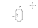
- the example shown in FIG. 12 is different from the case-side packing 14 of the embodiment in that an extending portion 14a extending in an arc shape is not provided.
- the case side packing 141 according to Modification 1 is formed of a soft material such as an elastomer resin, as in the embodiment.
- each of the lower ends of the case side packing 141 is provided with a holding portion 141 a that extends in a direction (front-rear direction) that closes the outlet 11. It has been.
- each of the holding portions 141a and 141a is arranged by shifting the phase in the left-right direction at the tip thereof so as not to overlap each other.
- the case-side packing 141 is formed with a Z-shaped cut by providing the pair of holding portions 141a and 141a. According to the household thin paper storage container 1 of the modified example 1 described above, similarly to the household thin paper storage container 1 of the embodiment, the household thin paper is not hindered from taking out the household thin paper that has fallen below the frame member. Can be suppressed.
- the bottom lid 40 or the like may be provided with a member that pushes up the thin paper laminate Q in the storage space S from below.
- the thin paper laminate Q can be sandwiched between the member and the case side packing 14 and the protrusion Y so that the thin paper laminate Q does not move in the storage space S. While being able to take out more smoothly from the taking-out port 11, it can suppress more effectively that the part which protruded from the taking-out port 11 of the household thin paper P falls in the storage space part S.
- the household thin paper storage container 1 is configured to store the household thin paper P stacked in a folding manner in which the side that is close to the upper surface has a low pop-up height and the height that pops up as it approaches the lower surface. It is also possible to do.
- the “pop-up height” means the vertical length of the upright portion of the uppermost household thin paper P, that is, the outlet 11 of the uppermost household thin paper P from the upper surface of the thin paper laminate Q. It is the length from the top to the upper end of the protruding part.
- the protruding length of the household thin paper P (the length of the portion protruding from the outlet 11) is long at the beginning of use and becomes shorter as the end of use is approached.
- the height of the pop-up is determined by the folding width. Therefore, the pop-up height is short at the beginning of use, and it is possible to fold so that it becomes longer as the end of use is approached.
- the thin paper laminate Q having such a folding method is used, the protruding length of the household thin paper P can be made almost constant from the beginning to the end of use, so that the portion protruding from the outlet 11 is the storage space portion.
- production which the part which fell in S and protruded from the extraction port 11 is bitten by the upper cover 20 at the time of opening and closing of the upper cover 20 can be suppressed.
- the present invention can also be applied to a configuration in which a cover body that opens and closes by rotating the open end in the vertical direction is provided on the upper surface of a case body for storing household thin paper.
- the detailed configuration of the household thin paper storage container can be changed as appropriate without departing from the gist of the present invention.
- the present invention can be used for household thin paper storage containers.
Landscapes
- Health & Medical Sciences (AREA)
- Public Health (AREA)
- Engineering & Computer Science (AREA)
- Mechanical Engineering (AREA)
- Containers And Packaging Bodies Having A Special Means To Remove Contents (AREA)
- Closures For Containers (AREA)
Priority Applications (4)
| Application Number | Priority Date | Filing Date | Title |
|---|---|---|---|
| KR1020177006590A KR102454283B1 (ko) | 2014-09-30 | 2015-09-29 | 가정용 박엽지 수납 용기 |
| US15/509,931 US10123667B2 (en) | 2014-09-30 | 2015-09-29 | Household tissue case |
| CN201580048286.3A CN106687391B (zh) | 2014-09-30 | 2015-09-29 | 家庭用薄纸收纳容器 |
| EP15847118.5A EP3202688B1 (en) | 2014-09-30 | 2015-09-29 | Household tissue storage container |
Applications Claiming Priority (2)
| Application Number | Priority Date | Filing Date | Title |
|---|---|---|---|
| JP2014-201106 | 2014-09-30 | ||
| JP2014201106A JP6210960B2 (ja) | 2014-09-30 | 2014-09-30 | 家庭用薄葉紙収納容器 |
Publications (1)
| Publication Number | Publication Date |
|---|---|
| WO2016052539A1 true WO2016052539A1 (ja) | 2016-04-07 |
Family
ID=55630565
Family Applications (1)
| Application Number | Title | Priority Date | Filing Date |
|---|---|---|---|
| PCT/JP2015/077579 WO2016052539A1 (ja) | 2014-09-30 | 2015-09-29 | 家庭用薄葉紙収納容器 |
Country Status (6)
Families Citing this family (7)
| Publication number | Priority date | Publication date | Assignee | Title |
|---|---|---|---|---|
| JP6280586B2 (ja) * | 2016-03-30 | 2018-02-14 | 大王製紙株式会社 | 衛生用薄葉紙収納容器 |
| JP6510696B1 (ja) * | 2018-03-05 | 2019-05-08 | 大王製紙株式会社 | 家庭用薄葉紙収納容器 |
| JP6975670B2 (ja) * | 2018-03-29 | 2021-12-01 | 大王製紙株式会社 | 家庭用薄葉紙収納容器 |
| CN108652503A (zh) * | 2018-05-24 | 2018-10-16 | 合肥智慧龙图腾知识产权股份有限公司 | 一种基于错位结构的自锁纸巾盒 |
| CN108852119A (zh) * | 2018-06-20 | 2018-11-23 | 南宁学院 | 一种可防污染的自锁抽纸盒 |
| JP7157705B2 (ja) * | 2019-06-03 | 2022-10-20 | 大王製紙株式会社 | 家庭用薄葉紙収納容器 |
| JP2021054494A (ja) * | 2019-09-30 | 2021-04-08 | 大王製紙株式会社 | 衛生用薄葉紙収納容器、衛生用薄葉紙収納容器の取出部材及び衛生用薄葉紙収納容器における取出部材の製造方法 |
Citations (3)
| Publication number | Priority date | Publication date | Assignee | Title |
|---|---|---|---|---|
| US20070215632A1 (en) * | 2006-03-16 | 2007-09-20 | The Procter & Gamble Company | Aperture for dispensing wipes |
| JP2013241190A (ja) * | 2012-05-18 | 2013-12-05 | Daio Paper Corp | 家庭用薄葉紙収納容器 |
| JP2013256322A (ja) * | 2012-06-13 | 2013-12-26 | Daio Paper Corp | 家庭用薄葉紙収納容器 |
Family Cites Families (9)
| Publication number | Priority date | Publication date | Assignee | Title |
|---|---|---|---|---|
| US4848575A (en) * | 1988-03-02 | 1989-07-18 | Eluci Company Inc. | Resealable dispenser-container for wet tissues |
| JP3410021B2 (ja) * | 1998-04-29 | 2003-05-26 | 株式会社タイキ | ウェットティッシュ包装体およびその製造方法 |
| JP3986247B2 (ja) | 1999-10-29 | 2007-10-03 | ピジョン株式会社 | 容器 |
| US6592004B2 (en) * | 2001-05-31 | 2003-07-15 | Kimberly-Clark Worldwide, Inc. | Flexible orifice for wet wipes dispenser |
| JP4606662B2 (ja) | 2001-08-03 | 2011-01-05 | 大王製紙株式会社 | ウェットティッシュ収容容器の取出口構造 |
| JP4522114B2 (ja) * | 2004-03-12 | 2010-08-11 | ユニ・チャーム株式会社 | ウェットティッシュ容器 |
| JP5486355B2 (ja) * | 2010-03-08 | 2014-05-07 | 日本製紙クレシア株式会社 | ウエットティシュ収納容器 |
| US8944279B2 (en) * | 2010-12-22 | 2015-02-03 | Kimberly-Clark Worldwide, Inc. | Wet wipe dispenser with improved arc-shaped dispensing partition |
| CN203211681U (zh) * | 2013-03-14 | 2013-09-25 | 花之町(厦门)日用品有限公司 | 一种湿巾包装袋 |
-
2014
- 2014-09-30 JP JP2014201106A patent/JP6210960B2/ja not_active Expired - Fee Related
-
2015
- 2015-09-29 KR KR1020177006590A patent/KR102454283B1/ko active Active
- 2015-09-29 CN CN201580048286.3A patent/CN106687391B/zh not_active Expired - Fee Related
- 2015-09-29 WO PCT/JP2015/077579 patent/WO2016052539A1/ja active Application Filing
- 2015-09-29 EP EP15847118.5A patent/EP3202688B1/en active Active
- 2015-09-29 US US15/509,931 patent/US10123667B2/en active Active
Patent Citations (3)
| Publication number | Priority date | Publication date | Assignee | Title |
|---|---|---|---|---|
| US20070215632A1 (en) * | 2006-03-16 | 2007-09-20 | The Procter & Gamble Company | Aperture for dispensing wipes |
| JP2013241190A (ja) * | 2012-05-18 | 2013-12-05 | Daio Paper Corp | 家庭用薄葉紙収納容器 |
| JP2013256322A (ja) * | 2012-06-13 | 2013-12-26 | Daio Paper Corp | 家庭用薄葉紙収納容器 |
Non-Patent Citations (1)
| Title |
|---|
| See also references of EP3202688A4 * |
Also Published As
| Publication number | Publication date |
|---|---|
| EP3202688A1 (en) | 2017-08-09 |
| CN106687391B (zh) | 2019-08-27 |
| JP6210960B2 (ja) | 2017-10-11 |
| CN106687391A (zh) | 2017-05-17 |
| JP2016069028A (ja) | 2016-05-09 |
| KR102454283B1 (ko) | 2022-10-12 |
| KR20170062447A (ko) | 2017-06-07 |
| EP3202688B1 (en) | 2021-07-28 |
| US10123667B2 (en) | 2018-11-13 |
| US20170303749A1 (en) | 2017-10-26 |
| EP3202688A4 (en) | 2017-08-09 |
Similar Documents
| Publication | Publication Date | Title |
|---|---|---|
| JP6210960B2 (ja) | 家庭用薄葉紙収納容器 | |
| RU2603563C2 (ru) | Пачка для курительных изделий с вытянутым проемом доступа | |
| JP6313472B2 (ja) | 包装組立体 | |
| JP2011168341A (ja) | 蓋付き容器 | |
| JP2010228766A (ja) | 家庭用薄葉紙収納容器 | |
| KR101088435B1 (ko) | 포장용 상자 | |
| JP6001918B2 (ja) | 家庭用薄葉紙収納容器 | |
| JP5990413B2 (ja) | 家庭用薄葉紙収納容器 | |
| JP2010228765A (ja) | 家庭用薄葉紙収納容器 | |
| JP6574094B2 (ja) | 家庭用薄葉紙収納容器 | |
| JP6174441B2 (ja) | 薄葉紙収納容器 | |
| JP6090969B2 (ja) | 家庭用薄葉紙収納容器 | |
| JP6147635B2 (ja) | 家庭用薄葉紙収納容器 | |
| JP6124647B2 (ja) | 薄葉紙収納容器 | |
| JP6066726B2 (ja) | 薄葉紙収納容器 | |
| JP6298510B2 (ja) | 薄葉紙収納容器 | |
| JP6128930B2 (ja) | 家庭用薄葉紙収納容器 | |
| JP6078281B2 (ja) | 薄葉紙収納容器 | |
| JP6072485B2 (ja) | 家庭用薄葉紙収納容器 | |
| JP6066576B2 (ja) | 家庭用薄葉紙収納容器及び家庭用薄葉紙収納容器の製造方法 | |
| JP6090968B2 (ja) | 家庭用薄葉紙収納容器 | |
| JP6220139B2 (ja) | 家庭用薄葉紙収納容器 | |
| JP6084360B2 (ja) | 家庭用薄葉紙収納容器 | |
| JP2012091835A (ja) | スライド式開閉蓋を有する収納容器 | |
| JP6043496B2 (ja) | ウェットティシュー収納容器 |
Legal Events
| Date | Code | Title | Description |
|---|---|---|---|
| 121 | Ep: the epo has been informed by wipo that ep was designated in this application |
Ref document number: 15847118 Country of ref document: EP Kind code of ref document: A1 |
|
| REEP | Request for entry into the european phase |
Ref document number: 2015847118 Country of ref document: EP |
|
| WWE | Wipo information: entry into national phase |
Ref document number: 2015847118 Country of ref document: EP |
|
| ENP | Entry into the national phase |
Ref document number: 20177006590 Country of ref document: KR Kind code of ref document: A |
|
| WWE | Wipo information: entry into national phase |
Ref document number: 15509931 Country of ref document: US |
|
| NENP | Non-entry into the national phase |
Ref country code: DE |