WO2016051807A1 - 判定方法、レーザ装置、及びセンサの製造方法 - Google Patents
判定方法、レーザ装置、及びセンサの製造方法 Download PDFInfo
- Publication number
- WO2016051807A1 WO2016051807A1 PCT/JP2015/005011 JP2015005011W WO2016051807A1 WO 2016051807 A1 WO2016051807 A1 WO 2016051807A1 JP 2015005011 W JP2015005011 W JP 2015005011W WO 2016051807 A1 WO2016051807 A1 WO 2016051807A1
- Authority
- WO
- WIPO (PCT)
- Prior art keywords
- metal body
- cylindrical metal
- contour
- determination method
- measurement
- Prior art date
- Legal status (The legal status is an assumption and is not a legal conclusion. Google has not performed a legal analysis and makes no representation as to the accuracy of the status listed.)
- Ceased
Links
Images

Classifications
-
- G—PHYSICS
- G06—COMPUTING OR CALCULATING; COUNTING
- G06T—IMAGE DATA PROCESSING OR GENERATION, IN GENERAL
- G06T7/00—Image analysis
- G06T7/0002—Inspection of images, e.g. flaw detection
- G06T7/0004—Industrial image inspection
- G06T7/001—Industrial image inspection using an image reference approach
-
- B—PERFORMING OPERATIONS; TRANSPORTING
- B23—MACHINE TOOLS; METAL-WORKING NOT OTHERWISE PROVIDED FOR
- B23K—SOLDERING OR UNSOLDERING; WELDING; CLADDING OR PLATING BY SOLDERING OR WELDING; CUTTING BY APPLYING HEAT LOCALLY, e.g. FLAME CUTTING; WORKING BY LASER BEAM
- B23K26/00—Working by laser beam, e.g. welding, cutting or boring
- B23K26/02—Positioning or observing the workpiece, e.g. with respect to the point of impact; Aligning, aiming or focusing the laser beam
- B23K26/03—Observing, e.g. monitoring, the workpiece
- B23K26/032—Observing, e.g. monitoring, the workpiece using optical means
-
- G—PHYSICS
- G01—MEASURING; TESTING
- G01N—INVESTIGATING OR ANALYSING MATERIALS BY DETERMINING THEIR CHEMICAL OR PHYSICAL PROPERTIES
- G01N21/00—Investigating or analysing materials by the use of optical means, i.e. using sub-millimetre waves, infrared, visible or ultraviolet light
- G01N21/84—Systems specially adapted for particular applications
- G01N21/88—Investigating the presence of flaws or contamination
-
- B—PERFORMING OPERATIONS; TRANSPORTING
- B23—MACHINE TOOLS; METAL-WORKING NOT OTHERWISE PROVIDED FOR
- B23K—SOLDERING OR UNSOLDERING; WELDING; CLADDING OR PLATING BY SOLDERING OR WELDING; CUTTING BY APPLYING HEAT LOCALLY, e.g. FLAME CUTTING; WORKING BY LASER BEAM
- B23K26/00—Working by laser beam, e.g. welding, cutting or boring
- B23K26/20—Bonding
- B23K26/21—Bonding by welding
- B23K26/24—Seam welding
- B23K26/244—Overlap seam welding
-
- B—PERFORMING OPERATIONS; TRANSPORTING
- B23—MACHINE TOOLS; METAL-WORKING NOT OTHERWISE PROVIDED FOR
- B23K—SOLDERING OR UNSOLDERING; WELDING; CLADDING OR PLATING BY SOLDERING OR WELDING; CUTTING BY APPLYING HEAT LOCALLY, e.g. FLAME CUTTING; WORKING BY LASER BEAM
- B23K26/00—Working by laser beam, e.g. welding, cutting or boring
- B23K26/20—Bonding
- B23K26/21—Bonding by welding
- B23K26/24—Seam welding
- B23K26/28—Seam welding of curved planar seams
- B23K26/282—Seam welding of curved planar seams of tube sections
-
- B—PERFORMING OPERATIONS; TRANSPORTING
- B23—MACHINE TOOLS; METAL-WORKING NOT OTHERWISE PROVIDED FOR
- B23K—SOLDERING OR UNSOLDERING; WELDING; CLADDING OR PLATING BY SOLDERING OR WELDING; CUTTING BY APPLYING HEAT LOCALLY, e.g. FLAME CUTTING; WORKING BY LASER BEAM
- B23K31/00—Processes relevant to this subclass, specially adapted for particular articles or purposes, but not covered by any single one of main groups B23K1/00 - B23K28/00
- B23K31/12—Processes relevant to this subclass, specially adapted for particular articles or purposes, but not covered by any single one of main groups B23K1/00 - B23K28/00 relating to investigating the properties, e.g. the weldability, of materials
- B23K31/125—Weld quality monitoring
-
- G—PHYSICS
- G01—MEASURING; TESTING
- G01B—MEASURING LENGTH, THICKNESS OR SIMILAR LINEAR DIMENSIONS; MEASURING ANGLES; MEASURING AREAS; MEASURING IRREGULARITIES OF SURFACES OR CONTOURS
- G01B11/00—Measuring arrangements characterised by the use of optical techniques
- G01B11/14—Measuring arrangements characterised by the use of optical techniques for measuring distance or clearance between spaced objects or spaced apertures
-
- G—PHYSICS
- G01—MEASURING; TESTING
- G01B—MEASURING LENGTH, THICKNESS OR SIMILAR LINEAR DIMENSIONS; MEASURING ANGLES; MEASURING AREAS; MEASURING IRREGULARITIES OF SURFACES OR CONTOURS
- G01B11/00—Measuring arrangements characterised by the use of optical techniques
- G01B11/24—Measuring arrangements characterised by the use of optical techniques for measuring contours or curvatures
-
- G—PHYSICS
- G01—MEASURING; TESTING
- G01N—INVESTIGATING OR ANALYSING MATERIALS BY DETERMINING THEIR CHEMICAL OR PHYSICAL PROPERTIES
- G01N21/00—Investigating or analysing materials by the use of optical means, i.e. using sub-millimetre waves, infrared, visible or ultraviolet light
- G01N21/84—Systems specially adapted for particular applications
- G01N21/88—Investigating the presence of flaws or contamination
- G01N21/8806—Specially adapted optical and illumination features
-
- G—PHYSICS
- G01—MEASURING; TESTING
- G01N—INVESTIGATING OR ANALYSING MATERIALS BY DETERMINING THEIR CHEMICAL OR PHYSICAL PROPERTIES
- G01N21/00—Investigating or analysing materials by the use of optical means, i.e. using sub-millimetre waves, infrared, visible or ultraviolet light
- G01N21/84—Systems specially adapted for particular applications
- G01N21/88—Investigating the presence of flaws or contamination
- G01N21/95—Investigating the presence of flaws or contamination characterised by the material or shape of the object to be examined
-
- G—PHYSICS
- G01—MEASURING; TESTING
- G01N—INVESTIGATING OR ANALYSING MATERIALS BY DETERMINING THEIR CHEMICAL OR PHYSICAL PROPERTIES
- G01N27/00—Investigating or analysing materials by the use of electric, electrochemical, or magnetic means
- G01N27/26—Investigating or analysing materials by the use of electric, electrochemical, or magnetic means by investigating electrochemical variables; by using electrolysis or electrophoresis
- G01N27/403—Cells and electrode assemblies
- G01N27/406—Cells and probes with solid electrolytes
- G01N27/407—Cells and probes with solid electrolytes for investigating or analysing gases
- G01N27/409—Oxygen concentration cells
-
- G—PHYSICS
- G06—COMPUTING OR CALCULATING; COUNTING
- G06T—IMAGE DATA PROCESSING OR GENERATION, IN GENERAL
- G06T7/00—Image analysis
- G06T7/70—Determining position or orientation of objects or cameras
-
- G—PHYSICS
- G01—MEASURING; TESTING
- G01N—INVESTIGATING OR ANALYSING MATERIALS BY DETERMINING THEIR CHEMICAL OR PHYSICAL PROPERTIES
- G01N2201/00—Features of devices classified in G01N21/00
- G01N2201/06—Illumination; Optics
- G01N2201/062—LED's
Definitions
- the present invention relates to a laser welding determination method, a laser device, and a sensor manufacturing method.
- Patent Document 1 discloses a method of determining welding failure by performing non-contact monitoring of reflected laser light or plasma light emitted from a welded part during laser welding.
- the present invention has been made to solve the above problems, and can be realized as the following modes.
- a determination method for performing determination regarding laser welding includes a step of measuring a position of at least one contour of the first cylindrical metal body and the second cylindrical metal body during the laser welding, and the first cylinder by the measurement. And determining whether or not at least one of the cylindrical metal body and the second cylindrical metal body is misaligned. According to the determination method of this embodiment, it is possible to determine whether or not there is a displacement in at least one of the first cylindrical metal body and the second cylindrical metal body during laser welding.
- the determination that there is no displacement means that the laser irradiation was performed at an appropriate position. For this reason, according to the determination method of this embodiment, it is possible to determine the presence / absence of a welding misalignment. Also, if laser irradiation is performed at an appropriate position, welding is performed well. For this reason, according to the determination method of this form, the quality of welding can be determined as a result by determining the presence or absence of position shift.
- the position of at least one of the first cylindrical metal body and the second cylindrical metal body is measured, and the measurement is performed. It may include a step of determining whether or not there is a displacement of at least one of the first cylindrical metal body and the second cylindrical metal body. According to the determination method of this aspect, it is possible to determine the position shift before welding, and thus it is possible to prevent the occurrence of welding failure. If it is determined that the position is shifted before welding, the position can be corrected before welding.
- the determination method of the above aspect further includes a position confirmation step of capturing an image of a reference object using a camera that captures the contour, and determining whether the camera is misaligned using the image. May be a feature. According to the determination method of this aspect, it is possible to determine a more accurate positional shift by determining the presence or absence of the positional shift of the camera itself.
- the measurement may be performed while rotating the first cylindrical metal body and the second cylindrical metal body around the axis during the laser welding. . According to this type of determination method, measurement can be performed from various angles. As a result, the welding misalignment can be determined more accurately.
- a laser device including an irradiation unit that irradiates a laser beam and a control unit that controls the irradiation unit.
- the laser apparatus includes a measuring unit that measures the position of at least one of the contours of the first cylindrical metal body and the second cylindrical metal body.
- the irradiation unit and the measurement unit are arranged such that the direction in which the irradiation unit irradiates the laser light and the direction in which the measurement unit measures are non-parallel.
- the control unit causes the measurement unit to measure the position at the time of irradiation by the irradiation unit, and the measurement causes a displacement of at least one of the first cylindrical metal body and the second cylindrical metal body. Determine presence or absence.
- the laser device of this aspect it is possible to determine whether or not the first cylindrical metal body and the second cylindrical metal body are misaligned during welding.
- the determination that there is no displacement means that the laser irradiation was performed at an appropriate position. For this reason, according to the laser apparatus of this embodiment, it is possible to determine the displacement of welding more accurately.
- a sensor manufacturing method including a step of laser welding a first cylindrical metal body and a second cylindrical metal body constituting the sensor.
- an image of a reference object is captured using a camera that captures an outline of at least one of the first cylindrical metal body and the second cylindrical metal body, and the camera is configured using the image.
- a position confirmation step for determining misalignment and a step of measuring the position of at least one of the contours of the first cylindrical metal body and the second cylindrical metal body using the camera during the laser welding. And determining whether or not there is a positional shift of at least one of the first cylindrical metal body and the second cylindrical metal body by the measurement.
- the sensor manufacturing method of this aspect it is possible to more accurately determine the welding displacement between the first cylindrical metal body and the second cylindrical metal body. Moreover, since welding is performed satisfactorily when the laser irradiation is performed at an appropriate position, according to this manufacturing method, the quality of the welding can be determined as a result.
- a determination method for performing determination regarding laser welding includes a step of measuring a contour of a predetermined portion of the first cylindrical metal body and a contour of the predetermined portion of the second cylindrical metal body, and the first cylindrical metal by the measurement. And a step of determining the presence / absence of displacement between the body and the second cylindrical metal body. According to the determination method of this embodiment, since it is possible to determine whether or not the first cylindrical metal body and the second cylindrical metal body are misaligned, it is possible to determine whether or not there is misalignment due to welding. Moreover, the quality of welding can be determined as a result by determining the presence or absence of position shift.
- the present invention can be realized in various forms, for example, in the form of a molded body obtained as a result of this determination method.
- FIG. 3 is a schematic diagram showing a laser device 600 from the side surface side of the gas sensor 10.
- Process drawing which shows the determination method which determines the presence or absence of position shift. An example of an image obtained by the measurement unit 630.
- the schematic diagram which shows a mode that the axis line CA of the main metal fitting 200 and the protector 300 and the rotating shaft of the fixing tool 610 shifted
- FIG. 1 is an explanatory diagram illustrating a cross-sectional configuration of a gas sensor 10 that is an example of a determination target.
- FIG. 1 illustrates a cross section of the gas sensor 10 cut along the axis CA, which is the central axis of the gas sensor 10.
- the lower side of the paper surface of the gas sensor 10 is referred to as “front end side”
- the upper side of the gas sensor 10 is referred to as “rear end side”.
- the gas sensor 10 is an oxygen sensor that is attached to an exhaust system of an internal combustion engine and detects oxygen (O 2 ) contained in the exhaust gas.
- the gas sensor 10 is a zirconia oxygen sensor using zirconium dioxide (ZrO 2 ).
- the gas sensor 10 includes a sensor element 100, a heating element 150, a metal shell 200, a protector 300, an outer cylinder 410, a first output terminal 520, a second output terminal 530, One lead wire 570, a second lead wire 580, and a third lead wire 590 are provided.
- the sensor element 100 of the gas sensor 10 constitutes an oxygen concentration cell that outputs an electromotive force according to the oxygen partial pressure.
- the sensor element 100 includes a solid electrolyte body 110, an inner electrode 120, and an outer electrode 130.
- the solid electrolyte body 110 of the sensor element 100 is made of a material having oxide ion conductivity (oxygen ion conductivity), and is formed in a bottomed cylindrical shape that extends along the axis CA and closes the tip side.
- the material of the solid electrolyte body 110 is zirconium oxide (ZrO 2 ) to which yttrium oxide (Y 2 O 3 ) is added, that is, yttria partially stabilized zirconia.
- the material of the solid electrolyte body 110 is an oxide selected from calcium oxide (CaO), magnesium oxide (MgO), cerium oxide (CeO 2 ), aluminum oxide (Al 2 O 3 ), and the like. Added partially stabilized zirconia may also be used.
- the inner electrode 120 of the sensor element 100 is formed so as to cover the inner side of the solid electrolyte body 110.
- the outer electrode 130 of the sensor element 100 is formed so as to cover the outer side of the solid electrolyte body 110.
- the material of the inner electrode 120 and the outer electrode 130 is platinum (Pt). In other embodiments, it may be a platinum alloy, other noble metals, or other noble metal alloys. In the present embodiment, the inner electrode 120 and the outer electrode 130 are formed by electroless plating.
- the heating element 150 of the gas sensor 10 is provided inside the sensor element 100 and generates heat based on electric power via the third lead wire 590 to heat the sensor element 100.
- the temperature of the sensor element 100 is kept constant by adjusting the electric power supplied from the third lead wire 590 to the heating element 150.
- the metal shell 200 of the gas sensor 10 is a cylindrical metal member.
- the sensor element 100 is held inside the metal shell 200.
- a screw part 210 is formed on the outer periphery of the metal shell 200, and the gas sensor 10 is attached to the exhaust pipe via the screw part 210.
- the protector 300 of the gas sensor 10 is a bottomed cylindrical metal member.
- the protector 300 is fixed to the distal end side of the metallic shell 200 so as to cover the sensor element 100 protruding from the distal end side of the metallic shell 200 and protects the sensor element 100.
- the protector 300 is formed with through holes 311 and 312 so that exhaust gas can be introduced into the sensor element 100.
- the metal shell 200 and the protector 300 are arranged such that the rotation axis coincides with the axis CA.
- the metal shell 200 and the protector 300 are overlapped at the overlap portion 170.
- the protector 300 is fixed to the metal shell 200 by forming the welded portion 180 by laser welding along the circumferential direction to the overlapping portion 170. The method for determining the presence or absence of misalignment in laser welding to the overlapping portion 170 will be described in detail later.
- the outer cylinder 410 of the gas sensor 10 is a cylindrical metal member.
- the outer cylinder 410 is fixed to the rear end side of the metal shell 200 so as to cover the sensor element 100, the heating element 150, the first output terminal 520, and the second output terminal 530 protruding from the rear end side of the metal shell 200.
- the sensor element 100, the heating element 150, the first output terminal 520, and the second output terminal 530 are protected.
- the sensor element 100 is configured to be able to introduce outside air inside the sensor element 100.
- the outside air introduced inside the sensor element 100 is used as a reference gas that serves as a reference for the gas sensor 10 to detect oxygen from the exhaust gas.
- the first output terminal 520 of the gas sensor 10 is a conductor that electrically connects the inner electrode 120 formed in the sensor element 100 and the first lead wire 570.
- the second output terminal 530 of the gas sensor 10 is a conductor that electrically connects the outer electrode 130 formed on the sensor element 100 and the second lead wire 580.
- the first lead wire 570 and the second lead wire 580 of the gas sensor 10 are electrically connected to a processing circuit (not shown) that processes the sensor output from the gas sensor 10.
- the inner electrode 120 functions as a reference electrode that is exposed to the outside air that is the reference gas
- the outer electrode 130 functions as a detection electrode that is exposed to the exhaust gas.
- an electromotive force is generated in the sensor element 100 according to the oxygen concentration difference between the reference gas and the exhaust gas.
- the electromotive force of the sensor element 100 is output as a sensor output to the outside of the gas sensor 10 via the first lead wire 570 and the second lead wire 580.
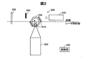
- FIG. 2 is a schematic diagram showing the laser device 600 from the rear end side of the gas sensor 10.
- the laser device 600 is used when forming the welded portion 180 between the metal shell 200 and the protector 300.
- the laser apparatus 600 includes a fixture 610, an irradiation unit 620, a measurement unit 630, a confirmation plate 640, an illumination 650, and a control unit 660.
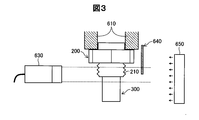
- FIG. 3 is a schematic diagram showing the laser device 600 from the side surface side of the gas sensor 10.
- the fixture 610 is a device that fixes the metallic shell 200.
- the fixture 610 can be rotated around the axis of the metal shell 200 and the protector 300 in a state where the metal shell 200 is fixed.
- the irradiation unit 620 is a device that irradiates a laser (see FIG. 2).
- the irradiation unit 620 can irradiate the overlapping portion 170 where the metal shell 200 and the protector 300 overlap with each other along the circumferential direction.
- the measuring unit 630 is a device that measures the position of at least one contour of the metal shell 200 and the protector 300.
- the measurement unit 630 uses a camera, but an infrared sensor may be used.
- the measurement by the measurement unit 630 is preferably performed with respect to the contour of the predetermined portion of the metal shell 200 and the contour of the predetermined portion of the protector 300.
- the confirmation plate 640 is provided between the measurement unit 630 and the illumination 650, and is formed of a metal plate.
- the confirmation plate 640 is a reference object used to confirm that the measurement unit 630 is formed at a correct position.
- the illumination 650 is provided in order to raise the outline of at least one of the metal shell 200 and the protector 300.
- the illumination 650 is provided so that the confirmation plate 640 and the illumination 650 overlap when viewed from the measurement unit 630.
- the illumination 650 uses LEDs.
- the control unit 660 is a control unit that controls each unit of the laser device.
- the control unit 660 includes a CPU, a RAM, and a ROM used for those controls.
- the irradiation unit 620 and the measurement unit 630 are configured such that the direction in which the irradiation unit 620 irradiates laser light and the direction in which the measurement unit 630 measures are non-parallel, that is, these two directions. Are arranged so as to cross each other.
- the “position shift” indicates at least one of a position shift of at least one of the metal shell 200 and the protector 300 with respect to the jig (fixing tool 610) and a position shift between the metal shell 200 and the protector 300.
- the measuring unit 630 measures the position of the contour on the side not irradiated with the laser light that does not include the contour on the side irradiated with the laser light among the contours of at least one of the metal shell 200 and the protector 300. . That is, as shown in FIG. 2, when the metal shell 200 and the protector 300 are divided into two parts on the irradiation unit 620 side (laser irradiation side in the drawing) and the opposite side (reverse side in the drawing), the measuring unit 630 is positioned on the opposite side. To do. Then, the measurement unit 630 measures the position of at least one of the metal shell 200 and the protector 300 on the side opposite to the side irradiated with the laser.
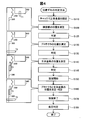
- FIG. 4 is a process diagram showing a determination method for determining whether or not there is a positional deviation.
- the “first cylindrical metal body” and the “second cylindrical metal body” in the “means for solving the problems” correspond to the “metal shell 200” and the “protector 300”.
- step S110 the control unit 660 controls the fixture 610, and the metal shell 200 into which the protector 300 is press-fitted is lifted and fixed by the fixture 610.
- step S120 the control unit 660 causes the measurement unit 630 to measure the position of the confirmation plate 640.
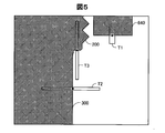
- FIG. 5 shows an example of an image obtained by the measurement unit 630.
- the region T1 is a region used when measuring the contour of the confirmation plate 640 as a reference object
- the region T2 is a region used when measuring the contour of the protector 300
- the region T3 is the contour of the metal shell 200. This is the area used when measuring In the subsequent steps, the measurement unit 630 measures the position of at least one contour of the metal shell 200, the protector 300, and the confirmation plate 640.
- the region T1, the region T2, and the region T3 are arranged so as to be able to determine the respective positional deviations without overlapping.
- step S120 the measurement unit 630 measures the position of the contour of the confirmation plate 640 in the region T1.
- step S125 the control unit 660 determines whether or not the measurement unit 630 is misaligned by measurement. Specifically, when the position of the contour of the confirmation plate 640 is within a predetermined allowable range with respect to the reference position stored in the control unit 660 in advance, the process proceeds to the next step. On the other hand, when the position of the contour of the confirmation plate 640 exceeds a predetermined allowable range with respect to the reference position stored in advance in the control unit 660, the control unit 660 is abnormal without moving to the next step.
- step S125 is a step of determining the positional deviation of the measurement unit 630 using the measurement unit 630 that captures at least one contour of the metal shell 200 and the protector 300. By this step, it is possible to determine whether or not the measurement unit 630 is displaced in the vertical direction.
- the region T1 is used for checking the reference position in the vertical direction.
- the reference position in the horizontal direction in addition to the vertical direction may be confirmed.
- various other objects other than the confirmation plate 640 can be used as a reference object used for determining whether or not the measurement unit 630 is misaligned.
- an object having a reference mark for example, a cross mark
- the presence or absence of misalignment of the measuring unit 630 is determined according to the position of the reference mark in the image, instead of determining the presence or absence of misalignment using the contour of the reference object.
- step S130 the control unit 660 causes the measurement unit 630 to measure the position of the protector 300.
- measurement unit 630 measures the position of the contour of protector 300 in region T2.
- the contour position is the position of the contour in the horizontal direction. This measurement may be performed with the metal shell 200 and the protector 300 stopped without rotating, or may be performed while rotating both.
- step S135 the control unit 660 determines whether or not the protector 300 is misaligned by measurement.
- the process proceeds to the next step.
- the control unit 660 does not move to the next step and the control unit 660 is abnormal. To the practitioner by sound or light, and waits until a signal indicating that the practitioner has confirmed is received. By this step, it is possible to determine whether or not the protector 300 is displaced in the horizontal direction.
- step S140 the control unit 660 causes the measuring unit 630 to measure the position of the metal shell 200.
- measurement unit 630 measures the position of the contour of metal shell 200 in region T3.
- the position of the contour is the position of the contour in the vertical direction. This measurement may be performed with the metal shell 200 and the protector 300 stopped without rotating, or may be performed while rotating both.
- step S145 the control unit 660 determines whether or not the metallic shell 200 is displaced by measurement.
- the process proceeds to the next step.
- the control unit 660 is abnormal without moving to the next step. The effect is notified to the practitioner by sound or light and waits until a signal indicating that the practitioner has confirmed is received. By this step, it is possible to determine whether or not the metal shell 200 is displaced in the vertical direction.
- a predetermined allowable range is exceeded with respect to the reference position stored in the control unit 660 in advance, the manufacture of defective products can be prevented beforehand by not proceeding to the next step.
- step S150 the control unit 660 starts welding. Specifically, in a state where the metal shell 200 and the protector 300 are rotated by the fixture 610, laser irradiation along the circumferential direction to the overlapping portion 170 is started by the irradiation unit 620.
- step S160 the control unit 660 measures the positions of the metal shell 200 and the protector 300 at the time of irradiation by the irradiation unit 620, and determines the presence or absence of misalignment using the measurement result.
- measurement unit 630 measures the position of the contour of protector 300 in region T2 and the position of the contour of metal shell 200 in region T3, and determines the presence or absence of misalignment. This measurement is preferably performed while rotating the metal shell 200 and the protector 300. The determination of the presence or absence of misalignment may be performed while rotating the metal shell 200 and the protector 300, or may be performed in a state where both are stopped (for example, after welding).
- the object to be measured is the contour of the object as in this embodiment, compared to the case where the light source is to be measured, compared to the case where the light source such as reflected light of laser light or plasma light is to be measured. It is possible to suppress a decrease in measurement accuracy due to objects other than the measurement target.
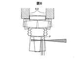
- FIG. 6 is a schematic diagram showing a state in which the axis CA of the metal shell 200 and the protector 300 and the rotation axis of the fixture 610 are deviated.
- the positions of the metal shell 200 and the protector 300 with respect to the focal point P of the laser change, so that the penetration at the laser welding position is not uniform.
- the positional deviation can be detected during welding even when the positional deviation is not detected before welding. That is, even when there is a position shift in a direction that is difficult to measure by the measurement unit 630 (measurement direction of the measurement unit 630 before rotation) in the state before welding, the position shift can be detected during welding.
- the position is measured three times or more while the metal shell 200 and the protector 300 are rotated once around the axis CA during the laser welding. By doing so, the position can be measured from various angles. For this reason, the presence or absence of the position shift of the metal shell 200 and the protector 300 can be determined more accurately, and as a result, the position shift of welding can be determined more accurately. For example, when three measurements are performed at equal intervals during one rotation, measurements at 120 ° intervals can be performed. In the present embodiment, the position is measured 10 to 15 times.
- control unit 660 does not determine that there is a position shift even when a position shift greater than one time less than a predetermined number is detected during laser welding, and the control unit 660 does not determine that there is a position shift. It is preferable to determine that there is a position shift when the position shift is detected. By doing in this way, noise can be removed and the presence or absence of welding position shift can be determined more accurately.
- the predetermined number of times is three.
- step S170 the control unit 660 ends the welding by the irradiation unit 620. Thereafter, in step S180, control unit 660 determines whether or not there is a welding failure due to misalignment. Specifically, if it is determined in step S160 that the metallic shell 200 or the protector 300 is not misaligned, it is determined that there is no welding failure due to misalignment. That is, when it is determined that there is no position shift during welding, it is determined that laser irradiation has been performed at an appropriate position.
- step S160 if it is determined in step S160 that at least one of the metal shell 200 or the protector 300 is misaligned, it is determined that there is a welding failure because the laser irradiation is not performed at an appropriate position. For this reason, the metal shell 200 and the protector 300 that have been welded are handled as defective products.
- step S135 of the above-described embodiment when the position of the protector 300 is within a predetermined allowable range with respect to the reference position stored in advance in the control unit 660, the process proceeds to the next step.
- step S135 the position of the region T2 or the reference position in the region T2 may be corrected.
- the position of the metal shell 200 when the position of the metal shell 200 is within a predetermined allowable range with respect to the reference position in step S145, the position of the region T3 or the reference position in the region T3 may be corrected. That is, when the positional deviation before welding is within an allowable range, the positions of the regions T2 and T3 and their reference positions are corrected based on the amount of positional deviation, and the corrected regions T2 and T3 are used in step S160.
- the positions of the contours of the protector 300 and the metal shell 200 may be measured. By doing in this way, position shift can be determined flexibly.
- the region where the position of the metal shell 200 in the vertical direction can be measured is a horizontal surface on the tip side of the screw portion 210, and this surface is narrow. For this reason, if the above correction
- the displacement in the vertical direction is determined (step S145).
- the horizontal displacement may be determined, or only one of the horizontal displacement and the vertical displacement may be determined. good.
- only the horizontal position shift with respect to the protector 300 is determined.
- only the vertical position shift with respect to the protector 300 may be determined, or the horizontal direction and the vertical direction may be determined. You may make it determine both of position shift.
- only the vertical position shift with respect to the metal shell 200 is determined.
- only the horizontal position shift with respect to the metal shell 200 may be determined, or may be determined to be perpendicular to the horizontal direction. You may make it determine both of the position shift of a direction.
- the present invention can also be applied to welding of cylindrical metal bodies constituting other types of sensors other than gas sensors. That is, according to the present invention, in the manufacturing process of the sensor, the first cylindrical metal body and the second cylindrical metal body are installed so that the axes coincide with each other to form an overlapping portion of the two. This is widely applicable when laser welding is performed on the part.
Landscapes
- Physics & Mathematics (AREA)
- Engineering & Computer Science (AREA)
- Optics & Photonics (AREA)
- General Physics & Mathematics (AREA)
- Health & Medical Sciences (AREA)
- Life Sciences & Earth Sciences (AREA)
- Chemical & Material Sciences (AREA)
- Mechanical Engineering (AREA)
- Immunology (AREA)
- Biochemistry (AREA)
- General Health & Medical Sciences (AREA)
- Analytical Chemistry (AREA)
- Pathology (AREA)
- Plasma & Fusion (AREA)
- Quality & Reliability (AREA)
- Computer Vision & Pattern Recognition (AREA)
- Theoretical Computer Science (AREA)
- Molecular Biology (AREA)
- Chemical Kinetics & Catalysis (AREA)
- Electrochemistry (AREA)
- Laser Beam Processing (AREA)
- Length Measuring Devices By Optical Means (AREA)
- Measuring Oxygen Concentration In Cells (AREA)
- Investigating Materials By The Use Of Optical Means Adapted For Particular Applications (AREA)
Abstract
Description
この形態の判定方法によれば、レーザ溶接の途中において、前記第1の筒状金属体及び前記第2の筒状金属体の少なくとも一方の位置ずれの有無を判定できる。ここで、位置ずれが無いという判定は、レーザ照射は適切な位置に行なわれたことを意味する。このため、この形態の判定方法によれば、溶接の位置ずれの有無を判定できる。また、レーザ照射が適切な位置に行なわれれば、溶接が良好に行なわれる。このため、この形態の判定方法によれば、位置ずれの有無を判定する事で、結果的に溶接の良否を判定できる。
この形態の判定方法によれば、溶接前に位置ずれを判定することができるため、溶接不良の発生を未然に防ぐことができる。また、溶接前に位置ずれと判定された場合には、位置を補正してから溶接することもできる。
この形態の判定方法によれば、カメラ自身の位置ずれの有無を判断することで、さらに正確な位置ずれを判定できる。
この形態の判定方法によれば、様々な角度から測定ができる。この結果、より正確に溶接の位置ずれを判定できる。
この形態の判定方法によれば、所定回数以上の位置ずれが検出されなければ、位置ずれとは判定されない。この結果、ノイズが除去でき、より正確に溶接の位置ずれを判定できる。
この形態の判定方法によれば、レーザ光の測定への影響を低減できる。この結果、より正確に溶接の位置ずれを判定できる。
この形態のレーザ装置によれば、溶接時において、前記第1の筒状金属体及び前記第2の筒状金属体の位置ずれの有無を判定できる。ここで、位置ずれが無いという判定は、レーザ照射は適切な位置に行なわれたことを意味する。このため、この形態のレーザ装置によれば、より正確に溶接の位置ずれを判定できる。
この形態のセンサの製造方法によれば、より正確に第1の筒状金属体と第2の筒状金属体の溶接の位置ずれを判定できる。また、レーザ照射が適切な位置に行なわれれば、溶接が良好に行なわれるため、この製造方法によれば、結果的に溶接の良否を判定できる。
この形態の判定方法によれば、前記第1の筒状金属体及び前記第2の筒状金属体の位置ずれの有無を判定できるので、溶接による位置ずれの有無を判定できる。また、位置ずれの有無を判定する事で、結果的に溶接の良否を判定できる。
A-1.ガスセンサの構成
図1は、判定対象の一例であるガスセンサ10の断面構成を示す説明図である。図1には、ガスセンサ10の中心軸である軸線CAに沿って切断したガスセンサ10の断面を図示した。本実施形態の説明において、ガスセンサ10の紙面下方側を「先端側」といい、ガスセンサ10の紙面上方側を「後端側」という。
図2は、ガスセンサ10の後端側からレーザ装置600を示す模式図である。本実施形態において、レーザ装置600は、主体金具200とプロテクタ300との溶接部180を形成する際に用いられる。レーザ装置600は、固定具610と、照射部620と、測定部630と、確認板640と、照明650と、制御部660を備える。
図4は、位置ずれの有無を判定する判定方法を示す工程図である。「課題を解決するための手段」における「第1の筒状金属体」と「第2の筒状金属体」とは、「主体金具200」と、「プロテクタ300」とに相当する。
本発明は、上述の実施形態や実施例、変形例に限られるものではなく、その趣旨を逸脱しない範囲において種々の構成で実現することができる。例えば、発明の概要の欄に記載した各形態中の技術的特徴に対応する実施形態、実施例、変形例中の技術的特徴は、上述の課題の一部または全部を解決するために、あるいは、上述の効果の一部または全部を達成するために、適宜、差し替えや、組み合わせを行うことが可能である。また、その技術的特徴が本明細書中に必須なものとして説明されていなければ、適宜、削除することが可能である。
100…センサ素子
110…固体電解質体
120…内側電極
130…外側電極
150…発熱体
170…重ね合せ部
180…溶接部
200…主体金具
210…ネジ部
300…プロテクタ
410…外筒
520…第1出力端子
530…第2出力端子
570…第1リード線
580…第2リード線
590…第3リード線
600…レーザ装置
610…固定具
620…照射部
630…測定部
640…確認板(基準物体)
650…照明
660…制御部
P…焦点
T1…領域
T2…領域
T3…領域
CA…軸線
Claims (17)
- 軸が一致するように配された第1の筒状金属体と第2の筒状金属体とが重なる重ね合せ部への、周方向に沿ったレーザ溶接に関する判定を行う判定方法であって、
前記レーザ溶接の途中において、前記第1の筒状金属体及び前記第2の筒状金属体の少なくとも一方の輪郭の位置を測定する工程と、
前記測定により前記第1の筒状金属体及び前記第2の筒状金属体の少なくとも一方の位置ずれの有無を判定する工程と、
を含むことを特徴とする、判定方法。 - 請求項1に記載の判定方法であって、更に、
前記レーザ溶接の前において、前記第1の筒状金属体及び前記第2の筒状金属体の少なくとも一方の輪郭の位置を測定し、前記測定により前記第1の筒状金属体及び前記第2の筒状金属体の少なくとも一方の位置ずれの有無を判定する工程を含む、
判定方法。 - 請求項1に記載の判定方法であって、更に、
前記輪郭を撮影するカメラを用いて基準物体の画像を撮影し、前記画像を用いて前記カメラの位置ずれの有無を判定する位置確認工程を有する、判定方法。 - 請求項1~3のいずれか一項に記載の判定方法であって、
前記レーザ溶接の途中において、前記軸を中心として前記第1の筒状金属体及び前記第2の筒状金属体を回転させながら前記測定を行なう、判定方法。 - 請求項4に記載の判定方法であって、
前記レーザ溶接の途中において、
前記位置ずれが1回よりも多い所定回数未満検出された場合においても前記位置ずれが有るものと判定せず、前記位置ずれが前記所定回数以上検出された場合に前記位置ずれが有るものと判定する、
判定方法。 - 請求項1に記載の判定方法であって、
前記測定する工程において、前記第1の筒状金属体及び前記第2の筒状金属体の少なくとも一方の輪郭のうち、レーザ光が照射される側の輪郭を含まず、前記レーザ光が照射されない側の輪郭を含む輪郭の位置を測定する、判定方法。 - 軸が一致するように配された第1の筒状金属体と第2の筒状金属体とが重なる重ね合せ部へ、周方向に沿ってレーザ光を照射する照射部と、前記照射部を制御する制御部と、を備えるレーザ装置であって、
前記第1の筒状金属体及び前記第2の筒状金属体の少なくとも一方の輪郭の位置を測定する測定部、
を備え、
前記照射部と前記測定部とは、前記照射部が前記レーザ光を照射する方向と、前記測定部が測定する方向とが非平行となるように配置されており、
前記制御部は、
前記照射部による照射時において、前記測定部に前記位置を測定させ、
前記測定により前記第1の筒状金属体及び前記第2の筒状金属体の少なくとも一方の位置ずれの有無を判定することを特徴とする、レーザ装置。 - 請求項7に記載のレーザ装置であって、
前記測定部はカメラであり、
前記制御部は、前記カメラに基準物体の画像を撮影させ、前記画像を用いて前記カメラの位置ずれの有無を判定する、レーザ装置。 - 請求項7または請求項8に記載のレーザ装置であって、
前記制御部は、レーザ溶接の途中において、前記軸を中心として前記第1の筒状金属体及び前記第2の筒状金属体を回転させながら前記測定部に測定を行なわせる、レーザ装置。 - 請求項7に記載のレーザ装置であって、
前記制御部は、前記第1の筒状金属体及び前記第2の筒状金属体の少なくとも一方の輪郭のうち、前記レーザ光が照射される側の輪郭を含まず、前記レーザ光が照射されない側の輪郭を含む輪郭の位置を、前記測定部に測定させる、レーザ装置。 - センサを構成する第1の筒状金属体と第2の筒状金属体とをレーザ溶接する工程を含む、センサの製造方法であって、
前記第1の筒状金属体及び前記第2の筒状金属体の少なくとも一方の輪郭を撮影するカメラを用いて基準物体の画像を撮影し、前記画像を用いて前記カメラの位置ずれを判定する位置確認工程と、
前記レーザ溶接の途中において、前記カメラを用いて前記第1の筒状金属体及び前記第2の筒状金属体の少なくとも一方の輪郭の位置を測定する工程と、
前記測定により前記第1の筒状金属体及び前記第2の筒状金属体の少なくとも一方の位置ずれの有無を判定する工程と、
を含むことを特徴とする、センサの製造方法。 - 請求項11に記載のセンサの製造方法であって、
前記レーザ溶接の途中において、軸を中心として前記第1の筒状金属体及び前記第2の筒状金属体を回転させながら前記測定を行なう、センサの製造方法。 - 請求項11に記載のセンサの製造方法であって、
前記測定する工程において、前記第1の筒状金属体及び前記第2の筒状金属体の少なくとも一方の輪郭のうち、レーザ光が照射される側の輪郭を含まず、前記レーザ光が照射されない側の輪郭を含む輪郭の位置を測定する、センサの製造方法。 - 軸が一致するように配された第1の筒状金属体と第2の筒状金属体とが重なる重ね合せ部への、周方向に沿ったレーザ溶接に関する判定を行う判定方法であって、
前記第1の筒状金属体の所定箇所の輪郭と、前記第2の筒状金属体の所定箇所の輪郭を、測定する工程と、
前記測定により前記第1の筒状金属体と前記第2の筒状金属体の位置ずれの有無を判定する工程と、
を含むことを特徴とする、判定方法。 - 請求項14に記載の判定方法であって、更に、
前記輪郭を撮影するカメラを用いて基準物体の画像を撮影し、前記画像を用いて前記カメラの位置ずれの有無を判定する位置確認工程を有する、判定方法。 - 請求項14または請求項15に記載の判定方法であって、
前記軸を中心として前記第1の筒状金属体及び前記第2の筒状金属体を回転させながら前記測定を行なう、判定方法。 - 請求項14に記載の判定方法であって、
前記測定する工程において、前記第1の筒状金属体及び前記第2の筒状金属体の少なくとも一方の輪郭のうち、レーザ光が照射される側の輪郭を含まず、前記レーザ光が照射されない側の輪郭を含む輪郭の位置を測定する、判定方法。
Priority Applications (5)
| Application Number | Priority Date | Filing Date | Title |
|---|---|---|---|
| KR1020177011281A KR101981410B1 (ko) | 2014-10-02 | 2015-10-01 | 판정방법, 레이저 장치 및 센서의 제조방법 |
| DE112015004532.5T DE112015004532B4 (de) | 2014-10-02 | 2015-10-01 | Bewertungsverfahren, Laservorrichtung und Verfahren zur Herstellung eines Sensors |
| JP2016551558A JP6254713B2 (ja) | 2014-10-02 | 2015-10-01 | 判定方法、レーザ装置、及びセンサの製造方法 |
| CN201580053046.2A CN107076678B (zh) | 2014-10-02 | 2015-10-01 | 判定方法、激光装置、及传感器的制造方法 |
| US15/511,282 US10713774B2 (en) | 2014-10-02 | 2015-10-01 | Assessment method, laser device, and sensor production method |
Applications Claiming Priority (2)
| Application Number | Priority Date | Filing Date | Title |
|---|---|---|---|
| JP2014203612 | 2014-10-02 | ||
| JP2014-203612 | 2014-10-02 |
Publications (1)
| Publication Number | Publication Date |
|---|---|
| WO2016051807A1 true WO2016051807A1 (ja) | 2016-04-07 |
Family
ID=55629869
Family Applications (1)
| Application Number | Title | Priority Date | Filing Date |
|---|---|---|---|
| PCT/JP2015/005011 Ceased WO2016051807A1 (ja) | 2014-10-02 | 2015-10-01 | 判定方法、レーザ装置、及びセンサの製造方法 |
Country Status (6)
| Country | Link |
|---|---|
| US (1) | US10713774B2 (ja) |
| JP (1) | JP6254713B2 (ja) |
| KR (1) | KR101981410B1 (ja) |
| CN (1) | CN107076678B (ja) |
| DE (1) | DE112015004532B4 (ja) |
| WO (1) | WO2016051807A1 (ja) |
Families Citing this family (1)
| Publication number | Priority date | Publication date | Assignee | Title |
|---|---|---|---|---|
| JP7357463B2 (ja) * | 2019-05-08 | 2023-10-06 | 株式会社東芝 | 判定装置、判定システム、溶接システム、判定方法、プログラム、及び記憶媒体 |
Citations (7)
| Publication number | Priority date | Publication date | Assignee | Title |
|---|---|---|---|---|
| JPH06106371A (ja) * | 1991-02-01 | 1994-04-19 | Toyo Seikan Kaisha Ltd | レーザビーム溶接方法 |
| JPH08136473A (ja) * | 1994-11-04 | 1996-05-31 | Toshiba Eng Co Ltd | 欠陥検出装置の調整方法、調整装置およびその基準板 |
| JPH1133760A (ja) * | 1997-07-18 | 1999-02-09 | Nissan Motor Co Ltd | ブランク材の突き合わせ溶接装置 |
| JP2001174414A (ja) * | 1999-12-20 | 2001-06-29 | Nkk Corp | 基準板,表面検査装置の調整方法及び表面検査装置用調整装置 |
| JP2004219154A (ja) * | 2003-01-10 | 2004-08-05 | Hitachi Ltd | 物体の表面形状計測方法及び自動溶接装置 |
| JP2010197247A (ja) * | 2009-02-25 | 2010-09-09 | Ngk Spark Plug Co Ltd | ガスセンサの製造方法 |
| WO2012147199A1 (ja) * | 2011-04-28 | 2012-11-01 | トヨタ自動車株式会社 | 溶接継手の突合せ位置検出方法、溶接継手の突合せ位置検出装置、溶接継手の製造方法 |
Family Cites Families (19)
| Publication number | Priority date | Publication date | Assignee | Title |
|---|---|---|---|---|
| JPH05146885A (ja) * | 1991-11-27 | 1993-06-15 | Toshiba Corp | レーザ加工装置 |
| DE19639667C1 (de) * | 1996-09-27 | 1998-03-12 | Daimler Benz Aerospace Airbus | Verfahren zum Schweißen von Profilen auf großformatigen Aluminium-Strukturbauteilen mittels Laserstrahlen |
| FR2778590B1 (fr) * | 1998-05-18 | 2000-08-04 | Alsthom Gec | Installation de soudage laser de pieces en chevauchement |
| US8110152B2 (en) * | 2001-07-12 | 2012-02-07 | Katcon Global S.A. | Gas sensor mounting boss and method of making |
| US6596961B2 (en) * | 2001-09-12 | 2003-07-22 | Fraunhofer Usa, Inc. | Method and apparatus for monitoring and adjusting a laser welding process |
| DE10234242B4 (de) * | 2002-07-09 | 2005-10-27 | Airbus Deutschland Gmbh | Anordnung und Verfahren zur Regelung der Nahtlage eines laserstrahlgefügten Profils |
| US6670574B1 (en) * | 2002-07-31 | 2003-12-30 | Unitek Miyachi Corporation | Laser weld monitor |
| JP4145719B2 (ja) * | 2003-05-30 | 2008-09-03 | 日本特殊陶業株式会社 | ガスセンサ及びガスセンサの製造方法 |
| DE102004016669B3 (de) * | 2004-01-07 | 2005-10-13 | Daimlerchrysler Ag | Verfahren zur Prüfung einer Laserschweissnaht |
| FR2866708B1 (fr) * | 2004-02-23 | 2006-03-24 | Commissariat Energie Atomique | Procede et dispositif de controle par ombroscopie |
| JP4518835B2 (ja) * | 2004-05-13 | 2010-08-04 | 大日本スクリーン製造株式会社 | 欠陥検出装置、配線領域抽出装置、欠陥検出方法および配線領域抽出方法 |
| DE102006004919A1 (de) * | 2006-02-01 | 2007-08-16 | Thyssenkrupp Steel Ag | Laserstrahlschweißkopf |
| US20090038150A1 (en) * | 2006-03-07 | 2009-02-12 | Daikin Industries, Ltd. | Method for producing compressor, and compressor |
| JP3962782B1 (ja) * | 2006-08-11 | 2007-08-22 | 国立大学法人 岡山大学 | 半田付けの検査方法、半田接合方法、及び半田接合装置 |
| KR100926550B1 (ko) * | 2007-11-30 | 2009-11-12 | 현대자동차주식회사 | 용접 품질 검사 시스템 및 그 검사 방법 |
| JP5142775B2 (ja) * | 2008-03-17 | 2013-02-13 | 川崎重工業株式会社 | 溶接品質検査方法および装置 |
| US8716627B2 (en) * | 2010-09-10 | 2014-05-06 | Honeywell International Inc. | Welding systems and methods |
| SE535767C2 (sv) * | 2011-04-28 | 2012-12-11 | Westinghouse Electric Sweden | Förfarande för svetsning av kärnbränslestav |
| JP5779152B2 (ja) | 2012-08-02 | 2015-09-16 | 株式会社神戸製鋼所 | 溶接開先部の位置及び形状計測方法 |
-
2015
- 2015-10-01 WO PCT/JP2015/005011 patent/WO2016051807A1/ja not_active Ceased
- 2015-10-01 DE DE112015004532.5T patent/DE112015004532B4/de active Active
- 2015-10-01 JP JP2016551558A patent/JP6254713B2/ja active Active
- 2015-10-01 KR KR1020177011281A patent/KR101981410B1/ko active Active
- 2015-10-01 CN CN201580053046.2A patent/CN107076678B/zh active Active
- 2015-10-01 US US15/511,282 patent/US10713774B2/en active Active
Patent Citations (7)
| Publication number | Priority date | Publication date | Assignee | Title |
|---|---|---|---|---|
| JPH06106371A (ja) * | 1991-02-01 | 1994-04-19 | Toyo Seikan Kaisha Ltd | レーザビーム溶接方法 |
| JPH08136473A (ja) * | 1994-11-04 | 1996-05-31 | Toshiba Eng Co Ltd | 欠陥検出装置の調整方法、調整装置およびその基準板 |
| JPH1133760A (ja) * | 1997-07-18 | 1999-02-09 | Nissan Motor Co Ltd | ブランク材の突き合わせ溶接装置 |
| JP2001174414A (ja) * | 1999-12-20 | 2001-06-29 | Nkk Corp | 基準板,表面検査装置の調整方法及び表面検査装置用調整装置 |
| JP2004219154A (ja) * | 2003-01-10 | 2004-08-05 | Hitachi Ltd | 物体の表面形状計測方法及び自動溶接装置 |
| JP2010197247A (ja) * | 2009-02-25 | 2010-09-09 | Ngk Spark Plug Co Ltd | ガスセンサの製造方法 |
| WO2012147199A1 (ja) * | 2011-04-28 | 2012-11-01 | トヨタ自動車株式会社 | 溶接継手の突合せ位置検出方法、溶接継手の突合せ位置検出装置、溶接継手の製造方法 |
Also Published As
| Publication number | Publication date |
|---|---|
| US20170301076A1 (en) | 2017-10-19 |
| KR101981410B1 (ko) | 2019-05-22 |
| DE112015004532T5 (de) | 2017-06-14 |
| JP6254713B2 (ja) | 2017-12-27 |
| CN107076678B (zh) | 2020-09-29 |
| KR20170060135A (ko) | 2017-05-31 |
| CN107076678A (zh) | 2017-08-18 |
| JPWO2016051807A1 (ja) | 2017-04-27 |
| DE112015004532B4 (de) | 2024-02-01 |
| US10713774B2 (en) | 2020-07-14 |
Similar Documents
| Publication | Publication Date | Title |
|---|---|---|
| EP3492214B1 (en) | Automatic car body welding spot inspection and control method | |
| US20120061357A1 (en) | Welding method including welding as a function of an ascertained welding distortion; welding device including a detection unit for detecting a misalignment of the workpieces; joined part | |
| JP5445718B2 (ja) | 溶接継手の突合せ位置検出方法、溶接継手の突合せ位置検出装置、溶接継手の製造方法 | |
| JP2004351434A (ja) | 溶接装置および方法 | |
| KR101754732B1 (ko) | 실시간 모니터링이 가능한 전극팁 검사장치 및 이를 구비한 용접장치 | |
| US20080237197A1 (en) | System and method for welding and real time monitoring of seam welded parts | |
| JP6254713B2 (ja) | 判定方法、レーザ装置、及びセンサの製造方法 | |
| JP2002331383A (ja) | 切断監視装置 | |
| JP4056934B2 (ja) | スパークプラグの製造方法及びスパークプラグの製造装置 | |
| JP6270931B2 (ja) | 点火プラグ用絶縁体の検査方法および検査装置 | |
| JP6875216B2 (ja) | ガスセンサ、および、ガスセンサの製造方法 | |
| US9205507B2 (en) | Nuclear power plant construction preparation unit, nuclear power plant construction system, and nuclear power plant construction method | |
| JP2015036653A (ja) | ガスセンサの製造方法、ガスセンサ及びガスセンサの取付け構造 | |
| KR20260012708A (ko) | 광 간섭 단층 촬영을 사용한 용접 경로의 식별 및 보정 | |
| JP5027172B2 (ja) | ガスセンサの製造方法 | |
| CN119124010A (zh) | 异种金属接合接头的检查方法、异种金属接合接头的检查装置、焊接方法以及焊接系统 | |
| WO2020261472A1 (ja) | レーザビームの異常検出方法及びレーザ加工装置 | |
| JP5878843B2 (ja) | スパークプラグの製造方法 | |
| EP3182535A1 (en) | Apparatus and method for manufacturing spark plug | |
| JP6708709B2 (ja) | スパークプラグの検査方法及びスパークプラグの製造方法 | |
| KR20010029268A (ko) | 자동차용 박판의 맞대기 레이저 용접 모니터링 방법 | |
| JP6392807B2 (ja) | スパークプラグの製造方法 | |
| JP2008014772A (ja) | 温度センサワークの検査装置および検査方法 | |
| KR101953888B1 (ko) | 결함 분석을 위한 3차원 검사 장비 및 이의 위치 보정 방법 | |
| JP2021041426A (ja) | 溶接線検出装置及び溶接線検出方法 |
Legal Events
| Date | Code | Title | Description |
|---|---|---|---|
| 121 | Ep: the epo has been informed by wipo that ep was designated in this application |
Ref document number: 15845844 Country of ref document: EP Kind code of ref document: A1 |
|
| ENP | Entry into the national phase |
Ref document number: 2016551558 Country of ref document: JP Kind code of ref document: A |
|
| WWE | Wipo information: entry into national phase |
Ref document number: 15511282 Country of ref document: US |
|
| WWE | Wipo information: entry into national phase |
Ref document number: 112015004532 Country of ref document: DE |
|
| ENP | Entry into the national phase |
Ref document number: 20177011281 Country of ref document: KR Kind code of ref document: A |
|
| 122 | Ep: pct application non-entry in european phase |
Ref document number: 15845844 Country of ref document: EP Kind code of ref document: A1 |