WO2016047360A1 - 金属二次電池用セパレータ - Google Patents
金属二次電池用セパレータ Download PDFInfo
- Publication number
- WO2016047360A1 WO2016047360A1 PCT/JP2015/074261 JP2015074261W WO2016047360A1 WO 2016047360 A1 WO2016047360 A1 WO 2016047360A1 JP 2015074261 W JP2015074261 W JP 2015074261W WO 2016047360 A1 WO2016047360 A1 WO 2016047360A1
- Authority
- WO
- WIPO (PCT)
- Prior art keywords
- polymer electrolyte
- negative electrode
- metal
- separator
- lithium
- Prior art date
- Legal status (The legal status is an assumption and is not a legal conclusion. Google has not performed a legal analysis and makes no representation as to the accuracy of the status listed.)
- Ceased
Links
Images





Classifications
-
- H—ELECTRICITY
- H01—ELECTRIC ELEMENTS
- H01M—PROCESSES OR MEANS, e.g. BATTERIES, FOR THE DIRECT CONVERSION OF CHEMICAL ENERGY INTO ELECTRICAL ENERGY
- H01M12/00—Hybrid cells; Manufacture thereof
- H01M12/08—Hybrid cells; Manufacture thereof composed of a half-cell of a fuel-cell type and a half-cell of the secondary-cell type
-
- H—ELECTRICITY
- H01—ELECTRIC ELEMENTS
- H01M—PROCESSES OR MEANS, e.g. BATTERIES, FOR THE DIRECT CONVERSION OF CHEMICAL ENERGY INTO ELECTRICAL ENERGY
- H01M10/00—Secondary cells; Manufacture thereof
- H01M10/05—Accumulators with non-aqueous electrolyte
- H01M10/058—Construction or manufacture
-
- H—ELECTRICITY
- H01—ELECTRIC ELEMENTS
- H01M—PROCESSES OR MEANS, e.g. BATTERIES, FOR THE DIRECT CONVERSION OF CHEMICAL ENERGY INTO ELECTRICAL ENERGY
- H01M10/00—Secondary cells; Manufacture thereof
- H01M10/05—Accumulators with non-aqueous electrolyte
- H01M10/052—Li-accumulators
-
- H—ELECTRICITY
- H01—ELECTRIC ELEMENTS
- H01M—PROCESSES OR MEANS, e.g. BATTERIES, FOR THE DIRECT CONVERSION OF CHEMICAL ENERGY INTO ELECTRICAL ENERGY
- H01M10/00—Secondary cells; Manufacture thereof
- H01M10/05—Accumulators with non-aqueous electrolyte
- H01M10/052—Li-accumulators
- H01M10/0525—Rocking-chair batteries, i.e. batteries with lithium insertion or intercalation in both electrodes; Lithium-ion batteries
-
- H—ELECTRICITY
- H01—ELECTRIC ELEMENTS
- H01M—PROCESSES OR MEANS, e.g. BATTERIES, FOR THE DIRECT CONVERSION OF CHEMICAL ENERGY INTO ELECTRICAL ENERGY
- H01M10/00—Secondary cells; Manufacture thereof
- H01M10/05—Accumulators with non-aqueous electrolyte
- H01M10/056—Accumulators with non-aqueous electrolyte characterised by the materials used as electrolytes, e.g. mixed inorganic/organic electrolytes
- H01M10/0564—Accumulators with non-aqueous electrolyte characterised by the materials used as electrolytes, e.g. mixed inorganic/organic electrolytes the electrolyte being constituted of organic materials only
- H01M10/0565—Polymeric materials, e.g. gel-type or solid-type
-
- H—ELECTRICITY
- H01—ELECTRIC ELEMENTS
- H01M—PROCESSES OR MEANS, e.g. BATTERIES, FOR THE DIRECT CONVERSION OF CHEMICAL ENERGY INTO ELECTRICAL ENERGY
- H01M50/00—Constructional details or processes of manufacture of the non-active parts of electrochemical cells other than fuel cells, e.g. hybrid cells
- H01M50/40—Separators; Membranes; Diaphragms; Spacing elements inside cells
- H01M50/409—Separators, membranes or diaphragms characterised by the material
- H01M50/411—Organic material
- H01M50/414—Synthetic resins, e.g. thermoplastics or thermosetting resins
-
- H—ELECTRICITY
- H01—ELECTRIC ELEMENTS
- H01M—PROCESSES OR MEANS, e.g. BATTERIES, FOR THE DIRECT CONVERSION OF CHEMICAL ENERGY INTO ELECTRICAL ENERGY
- H01M50/00—Constructional details or processes of manufacture of the non-active parts of electrochemical cells other than fuel cells, e.g. hybrid cells
- H01M50/40—Separators; Membranes; Diaphragms; Spacing elements inside cells
- H01M50/409—Separators, membranes or diaphragms characterised by the material
- H01M50/446—Composite material consisting of a mixture of organic and inorganic materials
-
- H—ELECTRICITY
- H01—ELECTRIC ELEMENTS
- H01M—PROCESSES OR MEANS, e.g. BATTERIES, FOR THE DIRECT CONVERSION OF CHEMICAL ENERGY INTO ELECTRICAL ENERGY
- H01M50/00—Constructional details or processes of manufacture of the non-active parts of electrochemical cells other than fuel cells, e.g. hybrid cells
- H01M50/40—Separators; Membranes; Diaphragms; Spacing elements inside cells
- H01M50/409—Separators, membranes or diaphragms characterised by the material
- H01M50/449—Separators, membranes or diaphragms characterised by the material having a layered structure
-
- H—ELECTRICITY
- H01—ELECTRIC ELEMENTS
- H01M—PROCESSES OR MEANS, e.g. BATTERIES, FOR THE DIRECT CONVERSION OF CHEMICAL ENERGY INTO ELECTRICAL ENERGY
- H01M50/00—Constructional details or processes of manufacture of the non-active parts of electrochemical cells other than fuel cells, e.g. hybrid cells
- H01M50/40—Separators; Membranes; Diaphragms; Spacing elements inside cells
- H01M50/409—Separators, membranes or diaphragms characterised by the material
- H01M50/449—Separators, membranes or diaphragms characterised by the material having a layered structure
- H01M50/451—Separators, membranes or diaphragms characterised by the material having a layered structure comprising layers of only organic material and layers containing inorganic material
-
- H—ELECTRICITY
- H01—ELECTRIC ELEMENTS
- H01M—PROCESSES OR MEANS, e.g. BATTERIES, FOR THE DIRECT CONVERSION OF CHEMICAL ENERGY INTO ELECTRICAL ENERGY
- H01M50/00—Constructional details or processes of manufacture of the non-active parts of electrochemical cells other than fuel cells, e.g. hybrid cells
- H01M50/40—Separators; Membranes; Diaphragms; Spacing elements inside cells
- H01M50/409—Separators, membranes or diaphragms characterised by the material
- H01M50/449—Separators, membranes or diaphragms characterised by the material having a layered structure
- H01M50/457—Separators, membranes or diaphragms characterised by the material having a layered structure comprising three or more layers
-
- H—ELECTRICITY
- H01—ELECTRIC ELEMENTS
- H01M—PROCESSES OR MEANS, e.g. BATTERIES, FOR THE DIRECT CONVERSION OF CHEMICAL ENERGY INTO ELECTRICAL ENERGY
- H01M50/00—Constructional details or processes of manufacture of the non-active parts of electrochemical cells other than fuel cells, e.g. hybrid cells
- H01M50/40—Separators; Membranes; Diaphragms; Spacing elements inside cells
- H01M50/46—Separators, membranes or diaphragms characterised by their combination with electrodes
-
- H—ELECTRICITY
- H01—ELECTRIC ELEMENTS
- H01M—PROCESSES OR MEANS, e.g. BATTERIES, FOR THE DIRECT CONVERSION OF CHEMICAL ENERGY INTO ELECTRICAL ENERGY
- H01M50/00—Constructional details or processes of manufacture of the non-active parts of electrochemical cells other than fuel cells, e.g. hybrid cells
- H01M50/40—Separators; Membranes; Diaphragms; Spacing elements inside cells
- H01M50/489—Separators, membranes, diaphragms or spacing elements inside the cells, characterised by their physical properties, e.g. swelling degree, hydrophilicity or shut down properties
- H01M50/491—Porosity
-
- H—ELECTRICITY
- H01—ELECTRIC ELEMENTS
- H01M—PROCESSES OR MEANS, e.g. BATTERIES, FOR THE DIRECT CONVERSION OF CHEMICAL ENERGY INTO ELECTRICAL ENERGY
- H01M2300/00—Electrolytes
- H01M2300/0017—Non-aqueous electrolytes
- H01M2300/0065—Solid electrolytes
- H01M2300/0082—Organic polymers
-
- H—ELECTRICITY
- H01—ELECTRIC ELEMENTS
- H01M—PROCESSES OR MEANS, e.g. BATTERIES, FOR THE DIRECT CONVERSION OF CHEMICAL ENERGY INTO ELECTRICAL ENERGY
- H01M4/00—Electrodes
- H01M4/02—Electrodes composed of, or comprising, active material
- H01M4/36—Selection of substances as active materials, active masses, active liquids
- H01M4/38—Selection of substances as active materials, active masses, active liquids of elements or alloys
-
- Y—GENERAL TAGGING OF NEW TECHNOLOGICAL DEVELOPMENTS; GENERAL TAGGING OF CROSS-SECTIONAL TECHNOLOGIES SPANNING OVER SEVERAL SECTIONS OF THE IPC; TECHNICAL SUBJECTS COVERED BY FORMER USPC CROSS-REFERENCE ART COLLECTIONS [XRACs] AND DIGESTS
- Y02—TECHNOLOGIES OR APPLICATIONS FOR MITIGATION OR ADAPTATION AGAINST CLIMATE CHANGE
- Y02E—REDUCTION OF GREENHOUSE GAS [GHG] EMISSIONS, RELATED TO ENERGY GENERATION, TRANSMISSION OR DISTRIBUTION
- Y02E60/00—Enabling technologies; Technologies with a potential or indirect contribution to GHG emissions mitigation
- Y02E60/10—Energy storage using batteries
-
- Y—GENERAL TAGGING OF NEW TECHNOLOGICAL DEVELOPMENTS; GENERAL TAGGING OF CROSS-SECTIONAL TECHNOLOGIES SPANNING OVER SEVERAL SECTIONS OF THE IPC; TECHNICAL SUBJECTS COVERED BY FORMER USPC CROSS-REFERENCE ART COLLECTIONS [XRACs] AND DIGESTS
- Y02—TECHNOLOGIES OR APPLICATIONS FOR MITIGATION OR ADAPTATION AGAINST CLIMATE CHANGE
- Y02E—REDUCTION OF GREENHOUSE GAS [GHG] EMISSIONS, RELATED TO ENERGY GENERATION, TRANSMISSION OR DISTRIBUTION
- Y02E60/00—Enabling technologies; Technologies with a potential or indirect contribution to GHG emissions mitigation
- Y02E60/30—Hydrogen technology
- Y02E60/50—Fuel cells
Definitions
- the present invention relates to a separator for a metal secondary battery.
- lithium, sodium, magnesium, zinc, and the like are used as negative electrodes for metal secondary batteries.
- lithium secondary batteries using lithium as an electrode are typical, such as mobile phones and laptop computers. It has already been put into practical use as a small power source.
- metal is melted from the negative electrode during discharging, and conversely, during charging, ions dissolved in the electrolytic solution are deposited as metal on the negative electrode.
- the electric field at that portion becomes locally strong, and metal ions are easily attracted.
- a sharp electric field tends to generate a stronger electric field, so that reduction of metal ions proceeds particularly at that position, and a tree-like elongated crystal grows. .
- Patent Literature 2 and Patent Literature 3 Conventional methods for suppressing the generation of dendrites include a method of modifying the electrode surface with an additive that acts on the negative electrode metal surface (for example, Patent Document 1), and formation of a ceramic composite layer or a solid electrolyte membrane on a separator (for example, Patent Literature 2 and Patent Literature 3) have been studied but have not been linked to effective performance improvement.
- the present invention has been made in view of the above circumstances, and an object thereof is to provide a separator that can suppress the generation of dendrite by making the electric field on the negative electrode surface of a metal secondary battery uniform.
- the present inventors have found that by forming a polymer electrolyte layer on at least one main surface layer of a separator made of polyimide, it is possible to suppress the generation of dendrites associated with charging and discharging of a metal secondary battery, and the present invention has been completed. It came to do.
- the first aspect of the present invention is a porous separator for a metal secondary battery in which a polymer electrolyte layer is formed on the surface layer of at least one main surface of a porous polyimide film.
- a second aspect of the present invention is a metal secondary battery in which an electrolyte and a porous separator for a metal secondary battery according to the first aspect of the present invention are disposed between a metal negative electrode and a positive electrode, A metal secondary battery in which a main surface on which a polymer electrolyte layer of the porous separator for a metal secondary battery is formed is disposed on the metal negative electrode side.
- the present invention it is possible to provide a separator that makes the electric field on the negative electrode surface of a metal secondary battery uniform and suppresses the generation of dendrites.
- the porous separator for a metal secondary battery according to the first aspect of the present invention is characterized in that a polymer electrolyte layer is formed on the surface layer of at least one main surface of the porous polyimide film.
- porous polyimide film used in the present invention is a film mainly composed of polyimide, which has pores opened on both main surfaces, and those in which individual pores communicate with each other inside the film are particularly limited. Can be used without
- the continuous micropores in the porous polyimide film are three-dimensionally ordered.
- the three-dimensional regular arrangement means a structure in which pores that are three-dimensionally adjacent to each other are connected to the entire porous polyimide film. Therefore, it is preferable to use a porous polyimide film having a 3 DOM (3-dimensional ordered macroporous) structure in which spherical holes are regularly adjacent to each other.
- the porous polyimide film having the 3DOM structure can be produced, for example, by a method using monodispersed spherical inorganic fine particles as a template.
- the 3DOM structure having a hexagonal close-packed structure can be formed.
- the pore size of the porous polyimide film can be easily controlled from the micro order to the nano order by selecting the particle size of the monodispersed spherical inorganic fine particles serving as a template.
- the size of the communication hole can be easily controlled, and a porous polyimide film for a separator having desired characteristics can be easily produced. Can do.
- porous polyimide film having 3DOM structure The porous polyimide film having the above-mentioned 3DOM structure can be produced, for example, by the following method.
- monodispersed spherical inorganic fine particles are dispersed in a solvent, and the dispersion is filtered through a filter to deposit the monodispersed spherical inorganic fine particles on the filter.
- An array is produced.
- any solvent may be used as long as it does not dissolve the inorganic fine particles and the filter.
- use of distilled water is simple and preferable.
- grains to deposit ie, the film thickness of a porous polyimide film
- grains to deposit can be controlled by changing the filtration amount per filter unit area of the inorganic fine particle to filter.
- the pore diameter of the separator can be finally controlled by changing the size of the inorganic fine particles.
- the pore diameter after elution of inorganic fine particles as a template is somewhat smaller than the particle diameter of the inorganic fine particles due to resin shrinkage or the like. Therefore, the diameter of the inorganic fine particles to be used may be selected in consideration of the finally required membrane porosity, resin shrinkage, and required pore diameter.
- the deposited body obtained above is fired to form a sintered body (finely packed regular array) of inorganic fine particles.
- the deposit may be peeled off from the filter, and fired and sintered.
- This firing treatment is performed to increase the strength of the inorganic fine particle sintered body. That is, the firing process sinters the inorganic fine particles, melts the inorganic fine particles, and increases the strength of the inorganic fine particle sintered body. This also ensures the formation of the communication hole.
- the degree of sintering of the inorganic fine particles can be controlled, and thereby the communication hole size of the porous polyimide film having a 3DOM structure can be controlled.
- the firing temperature may be a temperature that is equal to or higher than the temperature at which the inorganic fine particles used can be sintered, and the firing time may be an appropriate time according to the required communication hole size.
- the firing time may be an appropriate time according to the required communication hole size.
- silica fine particles when employed as the inorganic fine particles, it is preferable to perform a heat treatment at 1000 to 1100 ° C. for 30 minutes to 12 hours.
- the gap between the sintered bodies of the inorganic fine particles is filled with a varnish containing polyamic acid or polyimide, dried to remove the solvent, and further baked to obtain a composite of polyimide and sintered body.
- the impregnation of the varnish into the sintered body is not particularly limited and may be performed by any method, but is preferably impregnated by a vacuum impregnation filling method.
- the amount of the varnish to be impregnated is an amount such that the film thickness of the polyimide after drying is equal to or less than the film thickness of the sintered body.
- the baking conditions for polyimide are not particularly limited. For example, after raising the temperature from room temperature to 375 ° C. in 3 hours, the temperature is kept at 375 ° C. for 20 minutes, or the temperature is raised from room temperature to 375 ° C. in steps of 50 ° C. (each step is held for 20 minutes). In particular, a stepwise drying-thermal imidization method such as holding at 375 ° C. for 20 minutes can be used.
- the polyimide film containing the inorganic fine particle sintered body is immersed in a solution in which the inorganic fine particles are dissolved but the resin is not dissolved, and the inorganic fine particle sintered body is dissolved from the polyimide film containing the inorganic fine particle sintered body.
- a porous polyimide film having a 3DOM structure is finally formed. Then, you may wash
- inorganic fine particles for example, when silica is used as the inorganic fine particles, a polyimide containing the above-mentioned sintered inorganic fine particles with a low concentration of hydrogen fluoride water or the like with hydrochloric acid in the case of calcium carbonate It is possible to process and remove the inorganic fine particles by treating the film.
- the polyamic acid or polyimide is uniformly dissolved in advance in an organic solvent, varnished, and impregnated into the sintered body of inorganic fine particles.
- Manufacture of a varnish can be performed as follows, for example.
- a varnish containing polyamic acid or polyimide and an organic solvent is prepared.
- the varnish is prepared by mixing an organic solvent and polyamic acid or polyimide at an arbitrary ratio, or polymerizing polyamic acid in an organic solvent.
- polyamic acid to be used those obtained by polymerizing an arbitrary tetracarboxylic dianhydride and diamine can be used without any particular limitation.
- the amount of tetracarboxylic dianhydride and diamine used is not particularly limited, but 0.50 to 1.50 mol of diamine is preferably used relative to 1 mol of tetracarboxylic dianhydride, and 0.60 to 1. It is more preferable to use 30 mol, and it is particularly preferable to use 0.70 to 1.20 mol.
- the tetracarboxylic dianhydride can be appropriately selected from tetracarboxylic dianhydrides conventionally used as raw materials for polyamic acid synthesis.
- the tetracarboxylic dianhydride may be an aromatic tetracarboxylic dianhydride or an aliphatic tetracarboxylic dianhydride. From the viewpoint of the heat resistance of the resulting polyimide resin, the aromatic tetracarboxylic dianhydride may be used. Preference is given to using carboxylic dianhydrides. Tetracarboxylic dianhydride may be used in combination of two or more.
- the diamine can be appropriately selected from diamines conventionally used as a raw material for synthesizing polyamic acid.
- the diamine may be an aromatic diamine or an aliphatic diamine, but an aromatic diamine is preferred from the viewpoint of the heat resistance of the resulting polyimide resin. These diamines may be used in combination of two or more.
- aromatic diamines include diamino compounds in which one or about 2 to 10 phenyl groups are bonded. Specifically, phenylenediamine and derivatives thereof, diaminobiphenyl compounds and derivatives thereof, diaminodiphenyl compounds and derivatives thereof, diaminotriphenyl compounds and derivatives thereof, diaminonaphthalene and derivatives thereof, aminophenylaminoindane and derivatives thereof, diaminotetraphenyl Compounds and derivatives thereof, diaminohexaphenyl compounds and derivatives thereof, and cardo-type fluorenediamine derivatives.
- the means for producing the polyamic acid used in the present invention is not particularly limited, and for example, a known method such as a method of reacting an acid and a diamine component in an organic solvent can be used.
- the reaction between tetracarboxylic dianhydride and diamine is usually carried out in an organic solvent.
- the organic solvent used for the reaction of the tetracarboxylic dianhydride and the diamine may be any one that can dissolve the tetracarboxylic dianhydride and the diamine and does not react with the tetracarboxylic dianhydride and the diamine. It is not limited.
- An organic solvent can be used individually or in mixture of 2 or more types.
- organic solvents used in the reaction of tetracarboxylic dianhydride with diamine include N-methyl-2-pyrrolidone, N, N-dimethylacetamide, N, N-diethylacetamide, N, N-dimethylformamide, N Nitrogen-containing polar solvents such as N, diethylformamide, N-methylcaprolactam, N, N, N ′, N′-tetramethylurea; ⁇ -propiolactone, ⁇ -butyrolactone, ⁇ -valerolactone, ⁇ -valerolactone Lactone polar solvents such as ⁇ -caprolactone and ⁇ -caprolactone; dimethyl sulfoxide; acetonitrile; fatty acid esters such as ethyl lactate and butyl lactate; diethylene glycol dimethyl ether, diethylene glycol diethyl ether, dioxane, tetrahydrofuran, methyl cellosolve acetate,
- N-methyl-2-pyrrolidone N, N-dimethylacetamide, N, N-diethylacetamide, N, N-dimethylformamide, N, N- Nitrogen-containing polar solvents such as diethylformamide, N-methylcaprolactam, N, N, N ′, N′-tetramethylurea are preferred.
- the polymerization temperature is generally ⁇ 10 to 120 ° C., preferably 5 to 30 ° C.
- the polymerization time varies depending on the raw material composition used, but is usually 3 to 24 Hr (hour).
- the intrinsic viscosity of the polyamic acid organic solvent solution obtained under such conditions is preferably in the range of 1000 to 100,000 cP (centipoise), and more preferably in the range of 5,000 to 70,000 cP.
- the polyimide used in the present invention is not limited to its structure and molecular weight as long as it is a soluble polyimide that can be dissolved in the organic solvent used in the varnish of the present invention.
- a polyimide you may have a functional group which accelerates
- a monomer to introduce a flexible bending structure into the main chain in order to obtain a polyimide soluble in an organic solvent for example, ethylenediamine, hexamethylenediamine, 1,4-diaminocyclohexane, 1,3-diaminocyclohexane, Aliphatic diamines such as 4,4'-diaminodicyclohexylmethane; 2-methyl-1,4-phenylenediamine, o-tolidine, m-tolidine, 3,3'-dimethoxybenzidine, 4,4'-diaminobenzanilide, etc.
- an organic solvent for example, ethylenediamine, hexamethylenediamine, 1,4-diaminocyclohexane, 1,3-diaminocyclohexane, Aliphatic diamines such as 4,4'-diaminodicyclohexylmethane; 2-methyl-1,4-phenylenediamine
- Aromatic diamines such as polyoxyethylene diamine, polyoxypropylene diamine and polyoxybutylene diamine; polysiloxane diamines; 2,3,3 ′, 4′-oxydiphthalic anhydride, 3,4,3 ′ , 4'-oxydiphthalic anhydride, 2,2-bis (4- Hydroxyphenyl) propane dibenzoate-3,3 ', use of such 4,4'-tetracarboxylic dianhydride is valid.
- a monomer having a functional group that improves the solubility in an organic solvent for example, 2,2′-bis (trifluoromethyl) -4,4′-diaminobiphenyl, 2-trifluoromethyl-1,4 It is also effective to use a fluorinated diamine such as phenylenediamine.
- a monomer having a functional group that improves the solubility in an organic solvent for example, 2,2′-bis (trifluoromethyl) -4,4′-diaminobiphenyl, 2-trifluoromethyl-1,4
- a fluorinated diamine such as phenylenediamine.
- the same monomers as those described in the column for the polyamic acid can be used in combination as long as the solubility is not inhibited.
- the porous polyimide film of the present invention was obtained by preparing a varnish containing polyamic acid or polyimide and inorganic fine particles in addition to the porous polyimide film having the 3DOM structure, and forming the film once, followed by firing. It may be produced by removing an inorganic fine particle from a polyimide-inorganic fine particle composite film by selecting an appropriate method. At that time, at least part of the polyimide portion on the surface of the polyimide-inorganic fine particle composite film is removed before the step of removing the fine particles, or at least part of the surface of the porous polyimide film is removed after the step of removing the fine particles. You may provide the process to do.
- the baking conditions for polyimide are not particularly limited. For example, after raising the temperature from room temperature to 375 ° C. in 3 hours, the temperature is kept at 375 ° C. for 20 minutes, or the temperature is raised from room temperature to 375 ° C. in steps of 50 ° C. (each step is held for 20 minutes). Alternatively, a stepwise drying-thermal imidization method such as holding at 375 ° C. for 20 minutes can be used.
- the porous polyimide film of the present invention can be produced with good reproducibility by selecting an appropriate method from the polyimide-inorganic fine particle composite film obtained above and removing the inorganic fine particles.
- the method described in the description of the porous polyimide film having the 3DOM structure can be used without any particular limitation.
- the above varnish is prepared by mixing an organic solvent in which fine particles are dispersed in advance with polyamic acid or polyimide in an arbitrary ratio, or by polymerizing tetracarboxylic dianhydride and diamine in an organic solvent in which inorganic fine particles are dispersed in advance. It can be produced by using polyamic acid or further imidized to form polyimide, and finally the viscosity is preferably 300 to 1500 cP, more preferably 400 to 700 cP. If the viscosity of the varnish is within this range, it is possible to form a film uniformly.
- polyamic acid, polyimide, and inorganic fine particles to be used those described in the description of the porous polyimide film having the 3DOM structure can be used without particular limitation.
- the inorganic fine particles can be used without particular limitation as long as they are insoluble in the organic solvent used for the varnish and can be selectively removed after film formation.
- inorganic fine particles and polyamic acid or polyimide can be mixed so that the ratio of inorganic fine particles / polyimide is 2 to 6 (mass ratio) when the fine particles are baked into a polyimide-inorganic fine particle composite film. It is preferably 3 to 5 (mass ratio). Fine particles and polyamic acid or polyimide may be mixed so that the volume ratio of fine particles / polyimide is 1.5 to 4.5 when a polyimide-inorganic fine particle composite film is formed. More preferably, it is 1.8 to 3 (volume ratio).
- the polyimide / inorganic fine particle composite film has a fine particle / polyimide mass ratio of 2 or more, pores having an appropriate density as a separator can be obtained, and if it is 6 or less, viscosity increases and cracks in the film occur. Thus, it is possible to form a film stably without causing such problems.
- the fine particles used in the present invention preferably have a high sphericity and a small particle size distribution index.
- the fine particles having these conditions are excellent in dispersibility in the varnish and can be used in a state where they do not aggregate with each other.
- As the particle diameter (average diameter) of the fine particles used for example, those having a particle diameter of 100 to 2000 nm can be used. By satisfying these conditions, the pore diameter of the porous film obtained by removing the fine particles can be made uniform, so that the applied electric field can be made uniform, which is preferable.
- a dispersant is further added to the polyamic acid or a mixture of polyimide and a solvent together with the inorganic fine particles for the purpose of uniformly dispersing the inorganic fine particles. May be.
- the dispersant By adding the dispersant, the polyamic acid or polyimide and the inorganic fine particles can be mixed more uniformly, and furthermore, the inorganic fine particles in the film formed can be uniformly distributed.
- the above-mentioned dispersant is not particularly limited, and known ones can be used.
- palm fatty acid salt castor sulfate oil salt, lauryl sulfate salt, polyoxyalkylene allyl phenyl ether sulfate salt, alkylbenzene sulfonic acid, alkylbenzene sulfonate, alkyl diphenyl ether disulfonate, alkylnaphthalene sulfonate, dialkyl sulfosuccinate
- Anionic surfactants such as nate salt, isopropyl phosphate, polyoxyethylene alkyl ether phosphate salt, polyoxyethylene allyl phenyl ether phosphate salt; oleylamine acetate, lauryl pyridinium chloride, cetyl pyridinium chloride, lauryl trimethyl ammonium chloride, stearyl trimethyl ammonium chloride , Behenyltrimethylammoni
- the polymer electrolyte used for forming the polymer electrolyte layer of the present invention may be an intrinsic polymer electrolyte or a mixture of an organic polymer and a liquid electrolyte.
- the intrinsic polymer electrolyte is not particularly limited as long as it is an electrolyte that can interact with metal ions in the electrolytic solution.
- polyether PEO
- PEO polyether
- PEO fluoropolymer having perfluoroalkylene as a main skeleton and having an ion exchange group such as a sulfonic acid group or a carboxylic acid group at the end of a perfluorovinyl ether side chain
- PAA polyacrylic acid
- PSS polystyrene sulfonic acid
- PSS poly (allylamine hydrochloride)
- fluorine-based electrolyte polymers represented by perfluorosulfonic acid polymers are preferable because they are very high in chemical stability and are suitable as electrolyte membranes.
- a fluorine-based electrolyte polymer Nafion membrane (registered trademark, Du Pont), Dow membrane (Dow Chemical), Aciplex membrane (registered trademark, Asahi Kasei Kogyo Co., Ltd.), Flemion membrane (registered trademark, Asahi Glass ( Ltd.) etc. are known.
- One of the polymer electrolytes is a mixture of an organic polymer and a liquid electrolyte.
- a mixture obtained by mixing an organic polymer and a liquid electrolytic solution is generally called a gel electrolyte.
- PEO polyoxyethylene
- PAN polyacrylonitrile
- VdF vinylidene fluoride
- tetrafluoropropylene are used.
- a metal salt dissolved in an organic solvent can be used without particular limitation.
- the organic solvent include known hydrocarbon solvents such as propylene carbonate, ethylene carbonate, butylene carbonate, ⁇ -butyrolactone, 1,2-dimethoxyethane, 1,2-diethoxyethane, dimethyl carbonate, and diethyl carbonate;
- fluorine-based solvents such as fluoroethylene carbonate, fluoroether, and fluorinated carbonate can be used.
- the metal salt include metal salts such as LiClO 4 , LiAsF 6 , LiBF 4 , LiPF 6 , LiN (SO 2 CF 3 ) 2 , and LiN (SO 2 C 2 F 5 ) 2. However, it is not limited to these. Among these, LiPF 6 , LiBF 4 , LiN (SO 2 CF 3 ) 2 , LiN (SO 2 C 2 F 5 ) 2 , or a combination thereof is particularly preferable from the viewpoint of cycle characteristics.
- additives such as fillers, other polymers, and plasticizers may be further added to the above electrolyte polymer.
- the filler that can be added to the polymer electrolyte may be organic particles or inorganic particles. From the viewpoint of heat resistance, it is preferable to use inorganic fine particles. Specific examples of inorganic particles include, but are not limited to, silicon or metal oxides and ceramics.
- the oxide examples include SiO 2 , Al 2 O 3 , TiO 2 , CeO 2 , ZnO, and ZrO 2 .
- the ceramics may be either non-ionic conductive or ionic conductive, but it does not interfere with the ionic conductivity of the electrolyte polymer in the pores of the porous polyimide film. It is preferable to use sex ceramics.
- the diameter of the filler is not particularly limited. However, when the polymer electrolyte layer is formed by filling the pores of the porous polyimide film with the polymer electrolyte, the pores of the porous polyimide film are included. It is preferable to select a material sufficiently smaller than the pore diameter.
- the plasticizer is not particularly limited.
- an organic solvent for dissolving a metal salt such as polyethylene glycol dimethyl ester or high dielectric constant propylene carbonate can be used.
- the polymer electrolyte layer may be disposed so as to be interposed between the negative electrode metal and the porous polyimide film. For this reason, it is also possible to provide a polymer electrolyte layer directly on the negative electrode metal. However, in terms of ease of forming the polymer electrolyte layer and charge / discharge characteristics of the battery, a polymer electrolyte layer is provided on the surface of the porous polyimide film. It is more preferable.
- the polymer electrolyte layer is supported in contact with the main surface of the porous polyimide film and mainly includes only the polymer electrolyte, and a layer in which the polymer electrolyte is supported in the pores of the polyimide.
- the polymer electrolyte layer is preferably constituted by the polymer electrolyte material supported on the main surface of the porous polyimide film and the polymer electrolyte material supported in the pores in the layered region continuous from the main surface.
- the thickness of the electrolyte layer of the present invention is not limited, but the thinner the thickness, the lower the resistance, which is preferable for increasing the capacity retention rate of the battery.
- it is preferably 15 ⁇ m or less, more preferably 10 ⁇ m or less, further preferably 6 ⁇ m or less, and particularly preferably 5 ⁇ m or less.
- the thickness is preferably 5 ⁇ m or less. In this case, it is necessary to control the film thickness of the polymer electrolyte layer more strictly.
- a method for forming the layer made of the polymer electrolyte on the surface layer of at least one main surface of the porous polyimide film for example, a solution in which the polymer electrolyte is dissolved in an organic solvent is manufactured, and the polymer electrolyte solution is formed on the porous polyimide film.
- the method of filling a polymer electrolyte solution can be mentioned, it is not limited to these.
- a second aspect of the present invention is a metal secondary battery in which an electrolyte and a porous separator for a metal secondary battery according to the first aspect of the present invention are disposed between a metal negative electrode and a positive electrode.
- the main surface on which the polymer electrolyte layer of the porous separator for a metal secondary battery of the present invention is formed is used by being disposed on the metal negative electrode side.
- the type and configuration of the metal secondary battery of the present invention are not limited at all.
- a known metal secondary battery is particularly limited as long as it has a structure in which an electrolyte is impregnated into a battery element in which a positive electrode, a separator, and a negative electrode are sequentially laminated so that the above conditions are satisfied, and this is sealed in an exterior. It can be used without
- the metal secondary battery of the present invention may be a metal-air battery that utilizes atmospheric oxygen as the positive electrode active material.
- lithium (Li), magnesium (Mg), sodium (Na) and alloys of these with other metals can be used.
- the negative electrode when the secondary battery is a lithium metal secondary battery, the negative electrode includes lithium (metal lithium), lithium-aluminum, lithium-lead, lithium-bismuth, lithium-indium, lithium-gallium, lithium-indium- You may use what was comprised with lithium alloys, such as gallium. Specifically, these lithium or lithium alloys can be pressure-bonded to a current collector to form a negative electrode. In the case of a lithium alloy, the lithium content is preferably about 90% by mass or more.
- the thickness of the negative electrode is not particularly limited and can be set and used within a known range.
- the surface of the negative electrode becomes stable, so that the negative electrode can be thinned, and the capacity utilization of the negative electrode metal with respect to the positive electrode can be easily increased.
- the thickness excluding the current collector is preferably 15 to 700 ⁇ m. Preferably, it is 600 micrometers or less, More preferably, it is 100 micrometers or less.
- the positive electrode can have a structure in which a positive electrode mixture composed of a positive electrode active material, a conductive additive and a binder is formed on a current collector.
- a positive electrode using manganese dioxide as an active material can be used.
- a positive electrode having a structure in which a positive electrode mixture layer containing manganese dioxide, which is an active material, a conductive additive, and a binder, is formed on one side or both sides of a positive electrode current collector can be used.
- conductive assistants include carbon black, scaly graphite, ketjen black, acetylene black, and fibrous carbon.
- binders include polytetrafluoroethylene, polyvinylidene fluoride, carboxymethyl cellulose, and styrene butadiene. Rubber or the like is used.
- lithium oxide, lithium phosphorus oxide, lithium sulfide, lithium-containing transition metal oxide, or the like may be used as the positive electrode active material.
- LiCoO 2 , LiNiO 2 , LiMn 0.5 Ni 0.5 O 2 , LiCo 1/3 Ni 1/3 Mn 1/3 O 2 , LiMn 2 O 4 , LiFePO 4 , LiCo 0.5 Ni Examples include 0.5 O 2 and LiAl 0.25 Ni 0.75 O 2 .
- lithium salt examples include LiPF 6 , LiBF 4 , LiClO 4 and the like.
- non-aqueous solvent examples include propylene carbonate, ethylene carbonate, dimethyl carbonate, diethyl carbonate, ethyl methyl carbonate, ⁇ -butyrolactone, and vinylene carbonate. These may be used alone or in combination.
- the positive electrode used is composed of a catalyst layer that serves to absorb oxygen from the air and convert it into hydroxide ions and a current collector.
- the catalyst layer contains a current collector therein.
- the current collector may be in the center of the catalyst layer, or may be present in a layer form on one side of the catalyst layer.
- the current collector for the positive electrode materials in a form conventionally used as a current collector, such as a porous structure such as carbon paper and metal mesh, a network structure, fibers, and a nonwoven fabric, can be used without particular limitation.
- a metal mesh formed from SUS, nickel, aluminum, iron, titanium, or the like can be used.
- a metal foil having an oxygen supply hole can also be used.
- the catalyst layer contains an air electrode catalyst material.
- the air electrode catalyst material any of various catalysts can be used as long as it is a substance that receives electrons generated at the negative electrode and reduces oxygen.
- Mn 3 O 4 Mn 3 O 4
- carbon-based materials such as activated carbon, carbon, and carbon nanotubes
- Examples of exterior materials include metal cans or aluminum laminate packs.
- the shape of the battery includes a square shape, a cylindrical shape, a coin shape, and the like, but the porous separator of the present invention can be suitably applied to any shape.
- the battery case may be an open air type or a sealed type.
- the battery case that is open to the atmosphere has a structure in which at least the air electrode can sufficiently come into contact with the atmosphere.
- a sealed type it is preferable to provide an introduction pipe and an exhaust pipe for oxygen (air) which is a positive electrode active material.
- 3DOM polyimide separator A porous polyimide film having a 3DOM structure (hereinafter referred to as “3DOM polyimide separator”) was produced in the following manner, and then a polymer electrolyte layer was provided to obtain separators A to C.
- spherical silica (Seahoster (registered trademark) KE-P30 manufactured by Nippon Shokubai Co., Ltd., median average particle size 280 nm) was uniformly dispersed in 5 g of dimethylacetamide (DMAc) solvent.
- DMAc dimethylacetamide
- a polyamic acid solution (PMDA (pyromellitic acid dihydrate) / ODA (diaminodiphenyl ether), JFE Chemical) (5.5 g) was added to 10 g of this dispersion as a polyimide precursor. ] (Made by Shinkey Co., Ltd.) to obtain a silica / polyimide precursor slurry.
- the slurry was formed at a thickness of about 25 ⁇ m on a glass plate spin-coated with a phosphate ester release agent.
- Film formation was carried out using a doctor blade with an automatic film forming apparatus in an area of 10 cm ⁇ 10 cm. This is allowed to stand at room temperature for 5 hours, wait until the film naturally peels off from the glass plate, and after removing the release agent with methanol, it is fixed to a SUS mold, and 100 ° C. ⁇ 200 ° C. ⁇ 300 ° C. ⁇ Heat treatment was performed stepwise at 400 ° C. to complete imidization, and a silica-polyimide composite film was obtained.
- the silica-polyimide composite film was immersed in 10% by mass hydrogen fluoride water, and the silica was dissolved and removed over 6 hours. After removal, it was carefully washed with water to obtain a 3DOM polyimide separator.
- the above polymer electrolyte solution was dropped on a glass substrate and coated to a thickness of 5 ⁇ m.
- the polymer electrolyte solution was filled into the pores of the 3DOM polyimide separator by allowing the 3DOM polyimide separator to stand from above. Thereafter, the solvent was removed by vacuum drying, and the separator was peeled off from the glass substrate to produce a separator in which a polymer electrolyte layer was formed only on one side of the 3DOM polyimide separator.
- the cross section of the separator was observed with an SEM, it was confirmed that the polymer electrolyte filled the pores from the surface to approximately 8 ⁇ m.
- the thickness of the polymer electrolyte layer on the 3DOM polyimide separator was approximately 3 ⁇ m.
- ⁇ Reference Example 2> In an argon atmosphere dry box, a metal lithium having a thickness of 20 ⁇ m with a copper foil having a thickness of about 6 ⁇ m was placed on the glass substrate and the copper foil was left facing the glass substrate surface. The polymer electrolyte solution was applied to the metallic lithium using a doctor blade method. Thereafter, the DME solvent was removed by vacuum drying, and the negative electrode provided with the polymer electrolyte layer was peeled off from the glass substrate. The thickness of the polymer electrolyte layer formed on the metal lithium of the negative electrode was about 5 to 6 ⁇ m.
- the thickness of the polymer electrolyte layer can be controlled by the gap (coating thickness) of the blade when the polymer electrolyte solution is coated on the metallic lithium as the negative electrode.
- the gap (coating thickness) of the blade For example, when a 20 ⁇ m thick lithium metal and a 6 ⁇ m thick copper foil are allowed to stand on a glass substrate and a polymer electrolyte solution is applied with a gap of 50 ⁇ m thereon, the thickness of the polymer electrolyte solution is 24 (50-20-6) ⁇ m. Thereafter, it is dried and peeled off from the glass substrate, thereby producing a negative electrode having a polymer electrolyte layer having a thickness of 8 to 10 ⁇ m formed on the surface.
- a negative electrode provided with a polymer electrolyte layer was prepared in the same manner as in Reference Example 2 except that the concentration of the S-MES polymer in 1,2-dimethoxyethane (DME) was adjusted to 10% by weight as the polymer electrolyte solution. Produced.
- a negative electrode provided with a polymer electrolyte layer was produced in the same manner as in Reference Example 3 except that the thickness of the polymer electrolyte layer formed on the metallic lithium of the negative electrode was adjusted to 4 to 5 ⁇ m.
- the polymer electrolyte solution was applied with a gap of 40 ⁇ m.
- a negative electrode provided with a polymer electrolyte layer was produced in the same manner as in Reference Example 3 except that the thickness of the polymer electrolyte layer formed on the metallic lithium of the negative electrode was adjusted to 3 to 4 ⁇ m.
- the polymer electrolyte solution was applied with a gap of 30 ⁇ m.
- a slurry prepared by mixing active material LiCoO 2 (LCO) in 1-methyl-2-pyrrolidone (NMP) as a positive electrode active material, acetylene black as a conductive additive, and PVDF as a binder in a weight ratio of 92: 4: 4. was prepared.
- This slurry was applied onto a current collector Al foil and dried to prepare a coated electrode.
- the coated electrode was punched into a circle with a diameter of 14 mm to obtain a positive electrode.
- a negative electrode in which a metal lithium having a thickness of 20 ⁇ m with a copper foil having a thickness of 10 ⁇ m was punched out into a circle was used.
- the electrolyte used was a solution in which 1.0 moldm -3 LiPF 6 was dissolved in ethylene carbonate as a supporting salt.
- the above positive electrode, negative electrode, electrolyte and separator were incorporated into a 2032 type coin cell to produce the following evaluation cell.
- the separators A to B were used, respectively, and arranged so that the polymer electrolyte layer faced the negative electrode side.
- the untreated 3DOM separator was used as it was as the coin cell separator of Comparative Examples 1 and 3.
- the negative electrode was replaced with the negative electrode for reference evaluation, and an untreated 3DOM separator was used as it was.
- a battery charge / discharge device HJ1001SM8A (made by Hokuto Denko Co., Ltd.) and a charge / discharge test device TOSCAT-3000U (made by Toyo System Co., Ltd.) were used.
- a charge / discharge test was performed in a thermostatic chamber at 30 ° C. at 0 to 4.2V. Charging was performed up to 4.2V under the conditions of CC and 0.2C, and then up to 0.02C under the conditions of CV.
- the conditions for the cycle characteristic test after the initial cycle test were a charge / discharge test in a thermostatic chamber at 30 ° C. with a cut-off voltage of 3.0 to 4.2 V.
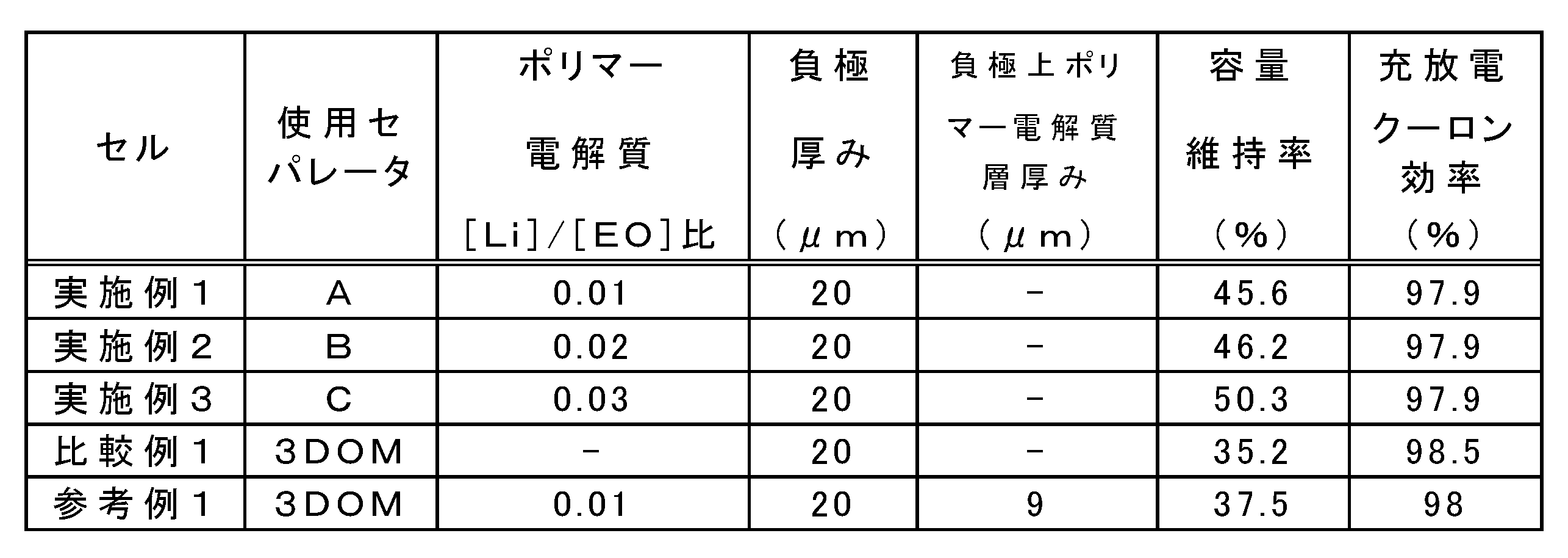
- Comparative Example 1 As can be seen from the results in Table 1, the capacity retention rate of Comparative Example 1 was 35.2%, while the capacity retention rates of Examples 1 to 3 using the separator of the present invention were 45.6 to This was 50.3%, which was a significant improvement over the value of Comparative Example 1. This result is considered due to the fact that the performance of the negative electrode was maintained even after 100 cycles by the polymer electrolyte layer in contact with the negative electrode surface.
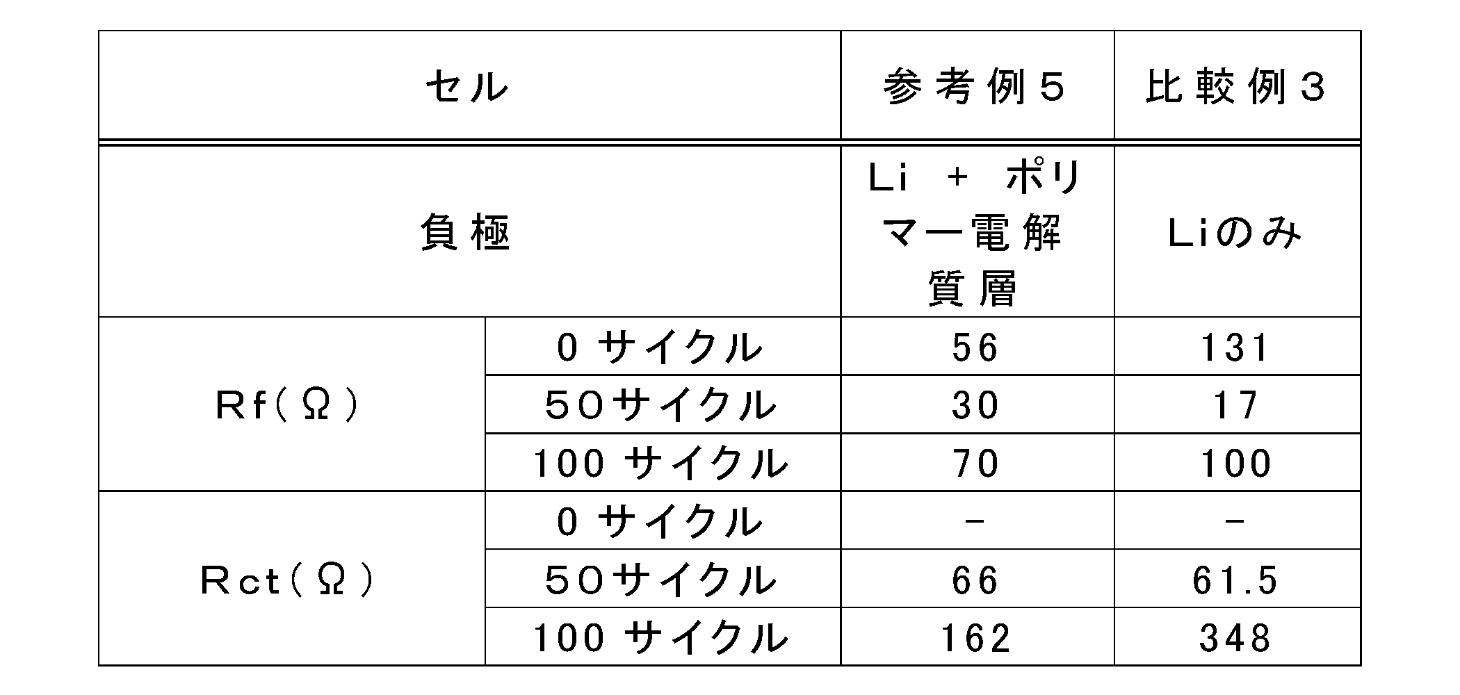
- the AC impedance is derived from the resistance (Rf) due to formation and growth of the solid electrolyte interface (SEI) on the electrode surface in the high frequency region, and to the charge transfer resistance (Rct) in the electrode, SEI, and electrolyte layer in the low frequency region. Derived from. After one cycle, the Rf of the coin cell of Example 3 decreases, suggesting that some ion conduction path is formed between the lithium metal negative electrode and the polymer electrolyte layer. Moreover, in Example 3, compared with the comparative example 1, the increase in Rct by a charging / discharging cycle test is suppressed, and stabilization of the lithium metal negative electrode surface by a polymer electrolyte layer is suggested.
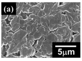
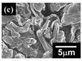
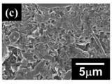
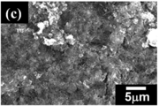
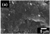
- FIGS. 1 to 3 show the surface of the lithium metal negative electrode after charging the amount corresponding to 100% of the LCO electrode capacity
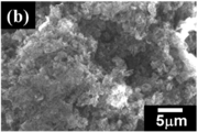
- FIGS. 4 to 11 show the surface of the lithium metal negative electrode after 100 cycles.
- 1 and 4 are based on a lithium metal negative electrode taken out from the corresponding coin cell of Comparative Example 1.
- FIG. 2 and 5 are based on the lithium metal negative electrode taken out from the corresponding coin cell of Example 3
- FIGS. 3 and 6 are based on the lithium metal negative electrode taken out from the coin cell corresponding to Comparative Example 2. is there.
- FIGS. 7 to 10 are based on lithium metal negative electrodes taken out from coin cells corresponding to Reference Examples 2 to 5.
- FIGS. FIG. 11 shows a lithium metal negative electrode taken out from the coin cell corresponding to Comparative Example 3.
- lithium dendrite was observed on the surface of the lithium metal negative electrode obtained from the coin cell using the polypropylene separator of Comparative Example 2.
- lithium precipitates are observed on the surface of the lithium metal negative electrode of Example 3 and Comparative Example 1 using the DOM separators of Examples 3 and 3 which are the separators of the present invention shown in FIGS. It is particulate and not acicular.
- the lithium metal negative electrode surface of Example 3 maintained a relatively smooth surface even after 100 cycles. This indicates that the use of the porous separator for a metal secondary battery in which the polymer electrolyte layer of the present invention is formed causes lithium to be smoothly deposited on the surface of the lithium metal negative electrode.
Landscapes
- Chemical & Material Sciences (AREA)
- Chemical Kinetics & Catalysis (AREA)
- Electrochemistry (AREA)
- General Chemical & Material Sciences (AREA)
- Engineering & Computer Science (AREA)
- Manufacturing & Machinery (AREA)
- Inorganic Chemistry (AREA)
- Materials Engineering (AREA)
- Composite Materials (AREA)
- Condensed Matter Physics & Semiconductors (AREA)
- General Physics & Mathematics (AREA)
- Physics & Mathematics (AREA)
- Dispersion Chemistry (AREA)
- Secondary Cells (AREA)
- Cell Separators (AREA)
- Hybrid Cells (AREA)
- Manufacture Of Porous Articles, And Recovery And Treatment Of Waste Products (AREA)
Abstract
Description
本発明において用いられる多孔質ポリイミドフィルムは、ポリイミドを主成分とするフィルムであって、両主表面に開口した孔を有し、フィルム内部で個々の細孔が連通したものが特に限定されることなく使用できる。
上記の3DOM構造を有する多孔質ポリイミドフィルムは、例えば、次のような方法によって製造することができる。
上記のとおり、多孔質ポリイミドフィルムを形成するに際し、予めポリアミド酸またはポリイミドを有機溶媒中に均一に溶解し、ワニス化して無機微粒子の焼結体への含浸を行う。ワニスの製造は、例えば、下記のとおりに行うことができる。
ワニスの調製は、有機溶剤とポリアミド酸またはポリイミドを任意の比率で混合するか、有機溶剤中でポリアミド酸を重合して行われる。
本発明の多孔質ポリイミドフィルムは、上記3DOM構造を有する多孔質ポリイミドフィルム以外にも、ポリアミド酸またはポリイミドと無機微粒子とを含有するワニスを準備し、一旦成膜したのち焼成して、得られたポリイミド-無機微粒子複合フィルムから、無機微粒子を適切な方法を選択して除去することにより製造してもかまわない。その際、上記微粒子を除去する工程の前に、ポリイミド-無機微粒子複合フィルム表面のポリイミド部分の少なくとも一部を除去するか、または、微粒子除去工程後に、多孔質ポリイミドフィルム表面の少なくとも一部を除去する工程を設けてもよい。
上記のワニスは、予め微粒子が分散した有機溶剤とポリアミド酸またはポリイミドを任意の比率で混合するか、無機微粒子を予め分散した有機溶剤中でテトラカルボン酸二無水物およびジアミンを重合してポリアミド酸とするか、さらにイミド化してポリイミドとすることで製造でき、最終的に、その粘度を300~1500cPとすることが好ましく、400~700cPの範囲がより好ましい。ワニスの粘度がこの範囲内であれば、均一に成膜をすることが可能である。
本発明のポリマー電解質層の形成に用いられるポリマー電解質は、真性のポリマー電解質であってもよく、あるいは有機ポリマーと液体電解質との混合物であってもよい。
本発明の第二の態様は、金属負極と正極との間に、電解液および本発明の第一の態様である金属二次電池用多孔質セパレータが配置された金属二次電池である。上記本発明の金属二次電池用多孔質セパレータのポリマー電解質層が形成された主表面を、上記金属負極側に配置して使用する。
<3DOMポリイミドセパレータの製造>
下記要領にて3DOM構造を有する多孔質ポリイミドフィルム(以下、「3DOMポリイミドセパレータ」という。)を製造した後、ポリマー電解質層を設けセパレータA~Cを得た。
ポリマー電解質のポリマー成分として、メタクリル酸のPEOエステル(PEGMA)とポリステレン(PSt)とのプロック共重合体が中心から放射状に伸びたスター構造ポリマー(S-MESポリマー)(日本曹達株式会社)を使用した。1,2-ジメトキシエタン(DME)に30重量%のS-MESポリマーを溶解した溶液に、リチウム塩(LiPF6)中のリチウム([Li])とS-MESポリマー中のエチレンオキシド([EO])の化学量論比が[Li]/[EO]=0.01となるよう、リチウム塩を添加しポリマー電解質溶液とした。
ポリマー電解質のリチウム塩を、化学量論比が[Li]/[EO]=0.02となるよう調節したほかは、セパレータAと同様にしてセパレータを作製した。
ポリマー電解質のリチウム塩を、化学量論比が[Li]/[EO]=0.03となるよう調節したほかは、セパレータAと同様にしてセパレータを作製した。
<参考例1>
アルゴン雰囲気ドライボックス内において、厚さ約10μmの銅箔の付いた厚さ20μmの金属リチウムをガラス基板上に、銅箔をガラス基板面に向けて静置した。前記金属リチウムに対し、上記のポリマー電解質溶液を、ドクターブレード法を用いて塗布した。その後、真空乾燥によりDME溶媒を除去し、ポリマー電解質層を設けた負極をガラス基板から剥離した。負極の金属リチウム上に形成されたポリマー電解質層の厚みは、およそ9μmであった。
アルゴン雰囲気ドライボックス内において、厚さ約6μmの銅箔の付いた厚さ20μmの金属リチウムをガラス基板上に、銅箔をガラス基板面に向けて静置した。前記金属リチウムに対し、上記のポリマー電解質溶液を、ドクターブレード法を用いて塗布した。その後、真空乾燥によりDME溶媒を除去し、ポリマー電解質層を設けた負極をガラス基板から剥離した。負極の金属リチウム上に形成されたポリマー電解質層の厚みは、およそ5~6μmであった。なお、ポリマー電解質層の厚みは、ポリマー電解質溶液を負極である金属リチウム上に塗工する際のブレードのギャップ(塗工厚み)によって制御できることが確認されている。例えば、ガラス基板上に厚さ20μmのリチウム金属と厚さ6μmの銅箔とを静置し、その上からギャップ50μmでポリマー電解質液を塗工した際には、ポリマー電解質溶液の厚みは、24(50-20-6)μmとなる。その後、乾燥させガラス基板から剥離することにより、表面に厚み8~10μmのポリマー電解質層が形成される負極が作製される。
ポリマー電解質溶液として、1,2-ジメトキシエタン(DME)中のS-MESポリマーの濃度を10重量%となるよう調節した以外は、参考例2と同様にして、ポリマー電解質層を設けた負極を作製した。
負極の金属リチウム上に形成されたポリマー電解質層の厚みを4~5μmとなるように調節した以外は、参考例3と同様にして、ポリマー電解質層を設けた負極を作製した。なお、本参考例では、ギャップ40μmでポリマー電解質溶液を塗工したものである。
負極の金属リチウム上に形成されたポリマー電解質層の厚みを3~4μmとなるように調節した以外は、参考例3と同様にして、ポリマー電解質層を設けた負極を作製した。なお、本参考例では、ギャップ30μmでポリマー電解質溶液を塗工したものである。
厚さ約10μmの銅箔の付いた厚さ20μmのリチウム金属のみを負極とした。
<比較例3>
厚さ約6μmの銅箔の付いた厚さ20μmのリチウム金属のみを負極とした。
正極活物質として、1-メチル-2-ピロリドン(NMP)中に、活物質LiCoO2(LCO)、導電助剤としてアセチレンブラック、バインダーとしてPVDFを92:4:4の重量比で混合してスラリーを調製した。このスラリーを、集電体Al箔上に塗布し、乾燥させて塗布電極を作製した。この塗布電極を、直径14mmの円形に打ち抜き、正極とした。また、負極には、厚さ10μmの銅箔の付いた厚さ20μmの金属リチウムを、円形に打ち抜いたものを使用した。
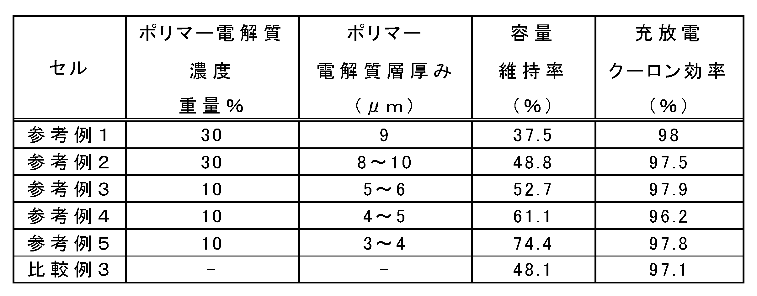
電池充放電装置HJ1001SM8A(北斗電工株式会社製)および充放電試験装置TOSCAT-3000U(東洋システム株式会社製)を用い、上記した試作コインセルを使用して、初期サイクル試験は、カットオフ電圧を3.0~4.2Vとして30℃の恒温槽内で充放電試験を行った。充電は、CC、0.2Cの条件で4.2Vまで行い、その後、CVの条件で0.02Cまで行った。初期サイクル試験後のサイクル特性試験の条件は、カットオフ電圧を3.0~4.2Vとして30℃の恒温槽内で充放電試験を行った。充電は、CC、1.0Cの条件で4.2Vまで行い、その後、CVの条件で0.1Cまで行った。放電は、CC、1.0Cの条件で3.0Vまで行った。各試作コインセルの充放電クーロン効率と容量維持率の評価結果を、表1及び表2に示す。
Solartron 1287型ポテンショ/ガルバノスタットおよび1255B型高周波応答アナライザを用い、30℃の恒温槽内で、実施例3および比較例1と参考例5および比較例3とのコインセルのサイクル特性試験前と、サイクル特性試験による、1サイクル、50サイクルおよび100サイクル後の電池の内部抵抗の測定を行った。測定条件は、入力交流振幅5mV、周波数範囲10mHz~1.0MHzである。サイクル特性試験前(0サイクル)、50サイクルおよび100サイクル後の各試作コインセルのRfおよびRcの評価結果を、表3および表4に示す。

実施例3と比較例1のコインセルにLCO電極容量の100%に相当する充電量を充電した後、および、上記充放電試験100サイクル後の実施例3と比較例1のコインセルから、それぞれリチウム負極を取出し、走査型電子顕微鏡JSM-5310、SEM(日本電子(株)製)を用いてその表面を観察した。また、市販のポリプロピレンセパレータを使用したコインセル(比較例2)において、同条件に供したリチウム負極を取出し同様の観察を行った。さらに、参考例2~5および比較例3のコインセルにおいて、同条件に供したリチウム負極を取出し同様の観察を行った。
Claims (4)
- 多孔質ポリイミドフィルムの少なくとも一方の主表面の表層にポリマー電解質層が形成された金属二次電池用多孔質セパレータ。
- 前記多孔質ポリイミドフィルムの少なくとも一方の主表面に担持されたポリマー電解質材料、および該主表面から連続する層状領域中の空孔内に担持されたポリマー電解質材料によって、前記ポリマー電解質層が構成される請求項1に記載の金属二次電池用多孔質セパレータ。
- 前記ポリマー電解質層が金属塩および/またはフィラーを含有する請求項1または2に記載の金属二次電池用多孔質セパレータ。
- 金属負極と正極との間に、電解液および1から3いずれか1項に記載の金属二次電池用多孔質セパレータが配置された金属二次電池であって、前記金属二次電池用多孔質セパレータのポリマー電解質層が形成された主表面が前記金属負極側に配置される金属二次電池。
Priority Applications (4)
| Application Number | Priority Date | Filing Date | Title |
|---|---|---|---|
| CN201580050383.6A CN107078256A (zh) | 2014-09-22 | 2015-08-27 | 金属二次电池用隔膜 |
| US15/510,768 US10930911B2 (en) | 2014-09-22 | 2015-08-27 | Separator for metal secondary batteries |
| KR1020177010553A KR102432559B1 (ko) | 2014-09-22 | 2015-08-27 | 금속 2차 전지용 세퍼레이터 |
| JP2016550059A JP6989263B2 (ja) | 2014-09-22 | 2015-08-27 | 金属二次電池用セパレータ |
Applications Claiming Priority (2)
| Application Number | Priority Date | Filing Date | Title |
|---|---|---|---|
| JP2014192995 | 2014-09-22 | ||
| JP2014-192995 | 2014-09-22 |
Publications (1)
| Publication Number | Publication Date |
|---|---|
| WO2016047360A1 true WO2016047360A1 (ja) | 2016-03-31 |
Family
ID=55580889
Family Applications (1)
| Application Number | Title | Priority Date | Filing Date |
|---|---|---|---|
| PCT/JP2015/074261 Ceased WO2016047360A1 (ja) | 2014-09-22 | 2015-08-27 | 金属二次電池用セパレータ |
Country Status (5)
| Country | Link |
|---|---|
| US (1) | US10930911B2 (ja) |
| JP (1) | JP6989263B2 (ja) |
| KR (1) | KR102432559B1 (ja) |
| CN (1) | CN107078256A (ja) |
| WO (1) | WO2016047360A1 (ja) |
Cited By (3)
| Publication number | Priority date | Publication date | Assignee | Title |
|---|---|---|---|---|
| JP2019133922A (ja) * | 2018-02-01 | 2019-08-08 | 東京応化工業株式会社 | 二次電池、及び二次電池用多孔質セパレータ |
| JP2020136187A (ja) * | 2019-02-22 | 2020-08-31 | 富士ゼロックス株式会社 | 全固体電池 |
| US12247103B2 (en) | 2021-09-07 | 2025-03-11 | Fujifilm Business Innovation Corp. | Polyimide precursor solution, porous polyimide film, separator for secondary battery, and secondary battery |
Families Citing this family (16)
| Publication number | Priority date | Publication date | Assignee | Title |
|---|---|---|---|---|
| CN110112354B (zh) * | 2018-02-01 | 2023-04-28 | 东京应化工业株式会社 | 二次电池及二次电池用多孔质隔膜 |
| CN108539263B (zh) * | 2018-04-18 | 2020-01-31 | 中国矿业大学(北京) | 一种三明治结构固态电解质的制备方法 |
| KR20200067434A (ko) * | 2018-12-04 | 2020-06-12 | 주식회사 엘지화학 | 리튬 이차전지용 음극의 제조방법 |
| JP7204885B2 (ja) * | 2019-01-10 | 2023-01-16 | エルジー エナジー ソリューション リミテッド | 固体電解質膜及びそれを含む全固体電池 |
| US11978851B2 (en) | 2019-03-05 | 2024-05-07 | Sk On Co., Ltd. | Coated separator for energy storage device |
| KR102834352B1 (ko) * | 2019-05-23 | 2025-07-15 | 주식회사 엘지에너지솔루션 | 리튬 이차 전지용 분리막, 이의 제조 방법, 및 이를 포함하는 리튬 이차 전지 |
| US11414166B2 (en) * | 2019-05-31 | 2022-08-16 | Ockerman Automation Consulting, Inc. | Marine vessel with hull-integrated electrical energy storage for vessel propulsion |
| KR102387069B1 (ko) * | 2019-08-06 | 2022-04-18 | 주식회사 비티엘첨단소재 | 이차전지용 알루미늄 파우치 필름 및 이의 제조방법 |
| US11652240B1 (en) * | 2019-12-03 | 2023-05-16 | GRU Energy Lab Inc. | Solid-state electrochemical cells comprising coated negative electrodes and methods of fabricating thereof |
| CN111463480B (zh) * | 2020-03-20 | 2022-10-14 | 东华大学 | 一种滤膜基高性能复合固态电解质薄膜及其制备方法和应用 |
| US12355102B2 (en) * | 2020-10-08 | 2025-07-08 | Ut-Battelle, Llc | Method of manufacturing a thin film composite solid electrolyte |
| CN115775915A (zh) * | 2021-09-08 | 2023-03-10 | 通用汽车环球科技运作有限责任公司 | 用于高功率固态电池组的聚合物凝胶电解质体系 |
| CN114388885A (zh) * | 2021-12-21 | 2022-04-22 | 浙江大学 | 一种不对称复合固态电解质膜及其制备方法和应用 |
| JP2025515770A (ja) * | 2022-05-25 | 2025-05-20 | 香港時代新能源科技有限公司 | セパレータ及びその製造方法、二次電池、電池モジュール、電池パック及び電力消費装置 |
| CN114976269A (zh) * | 2022-06-28 | 2022-08-30 | 肇庆市华师大光电产业研究院 | 一种无塑化剂嵌段共聚物固态电解质及其制备方法和应用 |
| CN117686497A (zh) * | 2024-02-01 | 2024-03-12 | 杭州百子尖科技股份有限公司 | 基于机器视觉隔膜喷涂检测方法、装置、电子设备及介质 |
Citations (3)
| Publication number | Priority date | Publication date | Assignee | Title |
|---|---|---|---|---|
| JP2003242954A (ja) * | 2002-02-19 | 2003-08-29 | Tdk Corp | 固体状電解質電池 |
| JP2005310795A (ja) * | 2004-04-24 | 2005-11-04 | Korea Electronics Telecommun | リチウム単イオン伝導無機添加剤を含むリチウム2次電池用複合高分子電解質及びその製造方法 |
| JP2008270160A (ja) * | 2007-03-28 | 2008-11-06 | Sanyo Electric Co Ltd | 非水電解質電池 |
Family Cites Families (17)
| Publication number | Priority date | Publication date | Assignee | Title |
|---|---|---|---|---|
| US5830603A (en) * | 1993-09-03 | 1998-11-03 | Sumitomo Electric Industries, Ltd. | Separator film for a storage battery |
| US6432586B1 (en) | 2000-04-10 | 2002-08-13 | Celgard Inc. | Separator for a high energy rechargeable lithium battery |
| KR100477751B1 (ko) | 2002-11-16 | 2005-03-21 | 삼성에스디아이 주식회사 | 비수계 전해액 및 이를 채용한 리튬 전지 |
| JP4329357B2 (ja) | 2003-02-24 | 2009-09-09 | 住友電気工業株式会社 | リチウム二次電池負極部材、及びその製造方法 |
| KR100496642B1 (ko) | 2003-04-25 | 2005-06-20 | 한국전자통신연구원 | 단이온 전도체를 포함하는 리튬 이차전지용 복합 고분자전해질 및 그 제조 방법 |
| EP1784876B1 (en) * | 2004-09-02 | 2018-01-24 | LG Chem, Ltd. | Organic/inorganic composite porous film and electrochemical device prepared thereby |
| KR101220677B1 (ko) * | 2005-04-28 | 2013-01-09 | 닛산 지도우샤 가부시키가이샤 | 비수 전해질 리튬 이온 전지용 정극 재료 및 이를 이용한 전지 |
| US20080241697A1 (en) | 2007-03-28 | 2008-10-02 | Sanyo Electric Co., Ltd. | Non-aqueous electrolyte battery |
| JP5331627B2 (ja) * | 2009-09-09 | 2013-10-30 | 公立大学法人首都大学東京 | リチウム二次電池用セパレーターおよびこれを用いたリチウム二次電池 |
| JP5900868B2 (ja) | 2009-11-24 | 2016-04-06 | 公立大学法人首都大学東京 | 多孔質ポリイミドおよびその製造方法 |
| WO2011096564A1 (ja) * | 2010-02-05 | 2011-08-11 | ダイキン工業株式会社 | 二次電池用ゲル電解質複合フィルム、及び、二次電池 |
| JP5632906B2 (ja) * | 2010-03-12 | 2014-11-26 | 株式会社日本触媒 | 吸水性樹脂の製造方法 |
| JP5605566B2 (ja) | 2010-11-18 | 2014-10-15 | 公立大学法人首都大学東京 | 多孔質ポリイミド膜の製造方法 |
| US11139534B2 (en) | 2011-12-09 | 2021-10-05 | Tokyo Metropolitan University | Lithium secondary battery separator and method of manufacturing same |
| US9397341B2 (en) * | 2012-10-10 | 2016-07-19 | Nthdegree Technologies Worldwide Inc. | Printed energy storage device |
| US9577289B2 (en) * | 2012-12-17 | 2017-02-21 | Sion Power Corporation | Lithium-ion electrochemical cell, components thereof, and methods of making and using same |
| JP6186783B2 (ja) * | 2013-03-19 | 2017-08-30 | ソニー株式会社 | セパレータ、電池、電池パック、電子機器、電動車両、蓄電装置および電力システム |
-
2015
- 2015-08-27 CN CN201580050383.6A patent/CN107078256A/zh active Pending
- 2015-08-27 KR KR1020177010553A patent/KR102432559B1/ko active Active
- 2015-08-27 WO PCT/JP2015/074261 patent/WO2016047360A1/ja not_active Ceased
- 2015-08-27 US US15/510,768 patent/US10930911B2/en not_active Expired - Fee Related
- 2015-08-27 JP JP2016550059A patent/JP6989263B2/ja not_active Expired - Fee Related
Patent Citations (3)
| Publication number | Priority date | Publication date | Assignee | Title |
|---|---|---|---|---|
| JP2003242954A (ja) * | 2002-02-19 | 2003-08-29 | Tdk Corp | 固体状電解質電池 |
| JP2005310795A (ja) * | 2004-04-24 | 2005-11-04 | Korea Electronics Telecommun | リチウム単イオン伝導無機添加剤を含むリチウム2次電池用複合高分子電解質及びその製造方法 |
| JP2008270160A (ja) * | 2007-03-28 | 2008-11-06 | Sanyo Electric Co Ltd | 非水電解質電池 |
Cited By (5)
| Publication number | Priority date | Publication date | Assignee | Title |
|---|---|---|---|---|
| JP2019133922A (ja) * | 2018-02-01 | 2019-08-08 | 東京応化工業株式会社 | 二次電池、及び二次電池用多孔質セパレータ |
| JP7246182B2 (ja) | 2018-02-01 | 2023-03-27 | 東京応化工業株式会社 | 二次電池、及び二次電池用多孔質セパレータ |
| JP2020136187A (ja) * | 2019-02-22 | 2020-08-31 | 富士ゼロックス株式会社 | 全固体電池 |
| JP7358745B2 (ja) | 2019-02-22 | 2023-10-11 | 富士フイルムビジネスイノベーション株式会社 | 全固体電池 |
| US12247103B2 (en) | 2021-09-07 | 2025-03-11 | Fujifilm Business Innovation Corp. | Polyimide precursor solution, porous polyimide film, separator for secondary battery, and secondary battery |
Also Published As
| Publication number | Publication date |
|---|---|
| CN107078256A (zh) | 2017-08-18 |
| US20170279101A1 (en) | 2017-09-28 |
| KR20170056693A (ko) | 2017-05-23 |
| JP6989263B2 (ja) | 2022-01-05 |
| KR102432559B1 (ko) | 2022-08-17 |
| US10930911B2 (en) | 2021-02-23 |
| JPWO2016047360A1 (ja) | 2017-09-14 |
Similar Documents
| Publication | Publication Date | Title |
|---|---|---|
| JP6989263B2 (ja) | 金属二次電池用セパレータ | |
| TWI603522B (zh) | Lithium battery separator and its manufacturing method | |
| JP5482173B2 (ja) | 電極合剤、電極および非水電解質二次電池 | |
| US9577256B2 (en) | Electrode mix, electrode mix paste, electrode, and non-aqueous electrolyte secondary battery | |
| JP6404426B2 (ja) | 二次電池用多孔質セパレータおよびそれを用いた二次電池 | |
| CN102763245A (zh) | 电极合剂、电极及锂二次电池 | |
| JP2019530128A (ja) | 電気化学発電装置用のイオン伝導性材料及び製造方法 | |
| JP2016040784A (ja) | セパレータ及びその製造方法 | |
| Zhang et al. | Advanced poly (vinyl alcohol) porous separator with overcharge protection function for lithium-ion batteries | |
| CN103299471A (zh) | 二次电池用非水电解质以及非水电解质二次电池 | |
| JP6520497B2 (ja) | リチウムイオン二次電池用負極活物質、リチウムイオン二次電池用負極およびリチウムイオン二次電池 | |
| EP4481926A1 (en) | Composite oil-based separator and preparation method therefor, and secondary battery | |
| WO2023182083A1 (ja) | 二次電池用組成物 | |
| US20250202057A1 (en) | Separator for electrochemical device, material and electrochemical device | |
| US20250202049A1 (en) | Separator for electrochemical device, material and electrochemical device | |
| CN121216063A (zh) | 隔膜及包含其的电化学装置和电子装置 | |
| WO2024204284A1 (ja) | 電極および電極の製造方法ならびに電気化学デバイス | |
| JP2026023172A (ja) | 非水電解液二次電池用積層セパレータ | |
| JP2025187410A (ja) | 多孔質膜、電気化学素子用セパレータ、電気化学素子用部材および電気化学素子 | |
| JP2025187412A (ja) | 多孔質膜、電気化学素子用セパレータ、電気化学素子用部材および電気化学素子 | |
| CN121282565A (zh) | 隔膜及包含其的电化学装置和电子装置 | |
| JP2025094881A (ja) | 電気化学素子用セパレータ、電気化学素子用部材および電気化学素子 | |
| US20190123381A1 (en) | Nonaqueous electrolyte secondary battery porous layer |
Legal Events
| Date | Code | Title | Description |
|---|---|---|---|
| 121 | Ep: the epo has been informed by wipo that ep was designated in this application |
Ref document number: 15843235 Country of ref document: EP Kind code of ref document: A1 |
|
| ENP | Entry into the national phase |
Ref document number: 2016550059 Country of ref document: JP Kind code of ref document: A |
|
| WWE | Wipo information: entry into national phase |
Ref document number: 15510768 Country of ref document: US |
|
| NENP | Non-entry into the national phase |
Ref country code: DE |
|
| ENP | Entry into the national phase |
Ref document number: 20177010553 Country of ref document: KR Kind code of ref document: A |
|
| 122 | Ep: pct application non-entry in european phase |
Ref document number: 15843235 Country of ref document: EP Kind code of ref document: A1 |