WO2016043293A1 - Mécanisme de palier pour turbocompresseur - Google Patents
Mécanisme de palier pour turbocompresseur Download PDFInfo
- Publication number
- WO2016043293A1 WO2016043293A1 PCT/JP2015/076575 JP2015076575W WO2016043293A1 WO 2016043293 A1 WO2016043293 A1 WO 2016043293A1 JP 2015076575 W JP2015076575 W JP 2015076575W WO 2016043293 A1 WO2016043293 A1 WO 2016043293A1
- Authority
- WO
- WIPO (PCT)
- Prior art keywords
- oil
- rotor shaft
- inner ring
- film damper
- bearing mechanism
- Prior art date
Links
Images


Classifications
-
- F—MECHANICAL ENGINEERING; LIGHTING; HEATING; WEAPONS; BLASTING
- F01—MACHINES OR ENGINES IN GENERAL; ENGINE PLANTS IN GENERAL; STEAM ENGINES
- F01D—NON-POSITIVE DISPLACEMENT MACHINES OR ENGINES, e.g. STEAM TURBINES
- F01D25/00—Component parts, details, or accessories, not provided for in, or of interest apart from, other groups
- F01D25/16—Arrangement of bearings; Supporting or mounting bearings in casings
- F01D25/162—Bearing supports
- F01D25/164—Flexible supports; Vibration damping means associated with the bearing
-
- F—MECHANICAL ENGINEERING; LIGHTING; HEATING; WEAPONS; BLASTING
- F16—ENGINEERING ELEMENTS AND UNITS; GENERAL MEASURES FOR PRODUCING AND MAINTAINING EFFECTIVE FUNCTIONING OF MACHINES OR INSTALLATIONS; THERMAL INSULATION IN GENERAL
- F16C—SHAFTS; FLEXIBLE SHAFTS; ELEMENTS OR CRANKSHAFT MECHANISMS; ROTARY BODIES OTHER THAN GEARING ELEMENTS; BEARINGS
- F16C19/00—Bearings with rolling contact, for exclusively rotary movement
- F16C19/02—Bearings with rolling contact, for exclusively rotary movement with bearing balls essentially of the same size in one or more circular rows
- F16C19/14—Bearings with rolling contact, for exclusively rotary movement with bearing balls essentially of the same size in one or more circular rows for both radial and axial load
- F16C19/18—Bearings with rolling contact, for exclusively rotary movement with bearing balls essentially of the same size in one or more circular rows for both radial and axial load with two or more rows of balls
- F16C19/181—Bearings with rolling contact, for exclusively rotary movement with bearing balls essentially of the same size in one or more circular rows for both radial and axial load with two or more rows of balls with angular contact
- F16C19/183—Bearings with rolling contact, for exclusively rotary movement with bearing balls essentially of the same size in one or more circular rows for both radial and axial load with two or more rows of balls with angular contact with two rows at opposite angles
-
- F—MECHANICAL ENGINEERING; LIGHTING; HEATING; WEAPONS; BLASTING
- F01—MACHINES OR ENGINES IN GENERAL; ENGINE PLANTS IN GENERAL; STEAM ENGINES
- F01D—NON-POSITIVE DISPLACEMENT MACHINES OR ENGINES, e.g. STEAM TURBINES
- F01D25/00—Component parts, details, or accessories, not provided for in, or of interest apart from, other groups
- F01D25/16—Arrangement of bearings; Supporting or mounting bearings in casings
-
- F—MECHANICAL ENGINEERING; LIGHTING; HEATING; WEAPONS; BLASTING
- F02—COMBUSTION ENGINES; HOT-GAS OR COMBUSTION-PRODUCT ENGINE PLANTS
- F02B—INTERNAL-COMBUSTION PISTON ENGINES; COMBUSTION ENGINES IN GENERAL
- F02B39/00—Component parts, details, or accessories relating to, driven charging or scavenging pumps, not provided for in groups F02B33/00 - F02B37/00
-
- F—MECHANICAL ENGINEERING; LIGHTING; HEATING; WEAPONS; BLASTING
- F04—POSITIVE - DISPLACEMENT MACHINES FOR LIQUIDS; PUMPS FOR LIQUIDS OR ELASTIC FLUIDS
- F04D—NON-POSITIVE-DISPLACEMENT PUMPS
- F04D29/00—Details, component parts, or accessories
- F04D29/05—Shafts or bearings, or assemblies thereof, specially adapted for elastic fluid pumps
- F04D29/053—Shafts
-
- F—MECHANICAL ENGINEERING; LIGHTING; HEATING; WEAPONS; BLASTING
- F04—POSITIVE - DISPLACEMENT MACHINES FOR LIQUIDS; PUMPS FOR LIQUIDS OR ELASTIC FLUIDS
- F04D—NON-POSITIVE-DISPLACEMENT PUMPS
- F04D29/00—Details, component parts, or accessories
- F04D29/05—Shafts or bearings, or assemblies thereof, specially adapted for elastic fluid pumps
- F04D29/056—Bearings
- F04D29/059—Roller bearings
-
- F—MECHANICAL ENGINEERING; LIGHTING; HEATING; WEAPONS; BLASTING
- F16—ENGINEERING ELEMENTS AND UNITS; GENERAL MEASURES FOR PRODUCING AND MAINTAINING EFFECTIVE FUNCTIONING OF MACHINES OR INSTALLATIONS; THERMAL INSULATION IN GENERAL
- F16C—SHAFTS; FLEXIBLE SHAFTS; ELEMENTS OR CRANKSHAFT MECHANISMS; ROTARY BODIES OTHER THAN GEARING ELEMENTS; BEARINGS
- F16C27/00—Elastic or yielding bearings or bearing supports, for exclusively rotary movement
- F16C27/04—Ball or roller bearings, e.g. with resilient rolling bodies
- F16C27/045—Ball or roller bearings, e.g. with resilient rolling bodies with a fluid film, e.g. squeeze film damping
-
- F—MECHANICAL ENGINEERING; LIGHTING; HEATING; WEAPONS; BLASTING
- F16—ENGINEERING ELEMENTS AND UNITS; GENERAL MEASURES FOR PRODUCING AND MAINTAINING EFFECTIVE FUNCTIONING OF MACHINES OR INSTALLATIONS; THERMAL INSULATION IN GENERAL
- F16C—SHAFTS; FLEXIBLE SHAFTS; ELEMENTS OR CRANKSHAFT MECHANISMS; ROTARY BODIES OTHER THAN GEARING ELEMENTS; BEARINGS
- F16C33/00—Parts of bearings; Special methods for making bearings or parts thereof
- F16C33/30—Parts of ball or roller bearings
- F16C33/58—Raceways; Race rings
- F16C33/583—Details of specific parts of races
- F16C33/586—Details of specific parts of races outside the space between the races, e.g. end faces or bore of inner ring
-
- F—MECHANICAL ENGINEERING; LIGHTING; HEATING; WEAPONS; BLASTING
- F16—ENGINEERING ELEMENTS AND UNITS; GENERAL MEASURES FOR PRODUCING AND MAINTAINING EFFECTIVE FUNCTIONING OF MACHINES OR INSTALLATIONS; THERMAL INSULATION IN GENERAL
- F16C—SHAFTS; FLEXIBLE SHAFTS; ELEMENTS OR CRANKSHAFT MECHANISMS; ROTARY BODIES OTHER THAN GEARING ELEMENTS; BEARINGS
- F16C35/00—Rigid support of bearing units; Housings, e.g. caps, covers
- F16C35/04—Rigid support of bearing units; Housings, e.g. caps, covers in the case of ball or roller bearings
- F16C35/06—Mounting or dismounting of ball or roller bearings; Fixing them onto shaft or in housing
- F16C35/07—Fixing them on the shaft or housing with interposition of an element
- F16C35/077—Fixing them on the shaft or housing with interposition of an element between housing and outer race ring
-
- F—MECHANICAL ENGINEERING; LIGHTING; HEATING; WEAPONS; BLASTING
- F01—MACHINES OR ENGINES IN GENERAL; ENGINE PLANTS IN GENERAL; STEAM ENGINES
- F01D—NON-POSITIVE DISPLACEMENT MACHINES OR ENGINES, e.g. STEAM TURBINES
- F01D5/00—Blades; Blade-carrying members; Heating, heat-insulating, cooling or antivibration means on the blades or the members
- F01D5/02—Blade-carrying members, e.g. rotors
- F01D5/04—Blade-carrying members, e.g. rotors for radial-flow machines or engines
-
- F—MECHANICAL ENGINEERING; LIGHTING; HEATING; WEAPONS; BLASTING
- F02—COMBUSTION ENGINES; HOT-GAS OR COMBUSTION-PRODUCT ENGINE PLANTS
- F02B—INTERNAL-COMBUSTION PISTON ENGINES; COMBUSTION ENGINES IN GENERAL
- F02B39/00—Component parts, details, or accessories relating to, driven charging or scavenging pumps, not provided for in groups F02B33/00 - F02B37/00
- F02B39/14—Lubrication of pumps; Safety measures therefor
-
- F—MECHANICAL ENGINEERING; LIGHTING; HEATING; WEAPONS; BLASTING
- F04—POSITIVE - DISPLACEMENT MACHINES FOR LIQUIDS; PUMPS FOR LIQUIDS OR ELASTIC FLUIDS
- F04D—NON-POSITIVE-DISPLACEMENT PUMPS
- F04D29/00—Details, component parts, or accessories
- F04D29/26—Rotors specially for elastic fluids
- F04D29/28—Rotors specially for elastic fluids for centrifugal or helico-centrifugal pumps for radial-flow or helico-centrifugal pumps
- F04D29/284—Rotors specially for elastic fluids for centrifugal or helico-centrifugal pumps for radial-flow or helico-centrifugal pumps for compressors
-
- F—MECHANICAL ENGINEERING; LIGHTING; HEATING; WEAPONS; BLASTING
- F05—INDEXING SCHEMES RELATING TO ENGINES OR PUMPS IN VARIOUS SUBCLASSES OF CLASSES F01-F04
- F05D—INDEXING SCHEME FOR ASPECTS RELATING TO NON-POSITIVE-DISPLACEMENT MACHINES OR ENGINES, GAS-TURBINES OR JET-PROPULSION PLANTS
- F05D2220/00—Application
- F05D2220/40—Application in turbochargers
-
- F—MECHANICAL ENGINEERING; LIGHTING; HEATING; WEAPONS; BLASTING
- F05—INDEXING SCHEMES RELATING TO ENGINES OR PUMPS IN VARIOUS SUBCLASSES OF CLASSES F01-F04
- F05D—INDEXING SCHEME FOR ASPECTS RELATING TO NON-POSITIVE-DISPLACEMENT MACHINES OR ENGINES, GAS-TURBINES OR JET-PROPULSION PLANTS
- F05D2240/00—Components
- F05D2240/50—Bearings
- F05D2240/54—Radial bearings
-
- F—MECHANICAL ENGINEERING; LIGHTING; HEATING; WEAPONS; BLASTING
- F05—INDEXING SCHEMES RELATING TO ENGINES OR PUMPS IN VARIOUS SUBCLASSES OF CLASSES F01-F04
- F05D—INDEXING SCHEME FOR ASPECTS RELATING TO NON-POSITIVE-DISPLACEMENT MACHINES OR ENGINES, GAS-TURBINES OR JET-PROPULSION PLANTS
- F05D2240/00—Components
- F05D2240/60—Shafts
-
- F—MECHANICAL ENGINEERING; LIGHTING; HEATING; WEAPONS; BLASTING
- F16—ENGINEERING ELEMENTS AND UNITS; GENERAL MEASURES FOR PRODUCING AND MAINTAINING EFFECTIVE FUNCTIONING OF MACHINES OR INSTALLATIONS; THERMAL INSULATION IN GENERAL
- F16C—SHAFTS; FLEXIBLE SHAFTS; ELEMENTS OR CRANKSHAFT MECHANISMS; ROTARY BODIES OTHER THAN GEARING ELEMENTS; BEARINGS
- F16C19/00—Bearings with rolling contact, for exclusively rotary movement
- F16C19/54—Systems consisting of a plurality of bearings with rolling friction
- F16C19/546—Systems with spaced apart rolling bearings including at least one angular contact bearing
- F16C19/547—Systems with spaced apart rolling bearings including at least one angular contact bearing with two angular contact rolling bearings
-
- F—MECHANICAL ENGINEERING; LIGHTING; HEATING; WEAPONS; BLASTING
- F16—ENGINEERING ELEMENTS AND UNITS; GENERAL MEASURES FOR PRODUCING AND MAINTAINING EFFECTIVE FUNCTIONING OF MACHINES OR INSTALLATIONS; THERMAL INSULATION IN GENERAL
- F16C—SHAFTS; FLEXIBLE SHAFTS; ELEMENTS OR CRANKSHAFT MECHANISMS; ROTARY BODIES OTHER THAN GEARING ELEMENTS; BEARINGS
- F16C2360/00—Engines or pumps
- F16C2360/23—Gas turbine engines
- F16C2360/24—Turbochargers
Definitions
- the present invention relates to a bearing mechanism for a turbocharger.
- turbocharger that compresses intake air using a gas flow of exhaust gas discharged from the internal combustion engine.
- the turbocharger includes a rotor shaft, a turbine impeller provided at one end of the rotor shaft, and a compressor impeller provided at the other end of the rotor shaft, and the rotor shaft is supported by a bearing mechanism.
- the bearing mechanism is housed in a bearing housing.
- Patent Document 1 includes, as such a bearing mechanism, a bearing mechanism having a ball bearing attached to the rotor shaft and an oil film damper filled with lubricating oil between the ball bearing and the bearing housing.
- a turbocharger is disclosed.
- the ball bearing includes an annular inner ring and an outer ring, and a ball interposed between the two so that both rotate with each other, and a rotor shaft is fitted inside the inner ring.
- the rotor assembly is formed so that the rotor shaft, both impellers provided at the end portions thereof, and the inner ring of the ball bearing rotate integrally.
- An oil film damper filled with oil is formed between the outer ring of the ball bearing and the bearing housing, and is configured to exhibit a damping effect for suppressing vibration of the rotating body assembly.
- the oil film damper is formed between the outer ring of the ball bearing and the bearing housing. Therefore, since the whole component located inside the oil film damper includes a ball bearing in addition to the rotor shaft and both impellers, the mass of the entire component inside the oil film damper is relatively large. Further, since the outer diameter of the outer ring of the ball bearing is sufficiently larger than the inner diameter of the inner ring, the contact area between the oil film damper and the outer ring of the ball bearing becomes relatively large. Therefore, the viscous force generated between the oil film damper and the outer ring is likely to increase, and the increase in the viscosity is particularly remarkable at low temperatures.
- both the impellers provided at both ends of the rotor shaft are in a cantilever state, in such a case, both the impellers greatly swing around as the rotor shaft rotates. As a result, there is a risk that abnormal noise may be generated at the beginning of rotation or the two impellers may come into contact with the housing and be damaged, which becomes more noticeable at low temperatures.
- the present invention has been made in view of such a background, and an object of the present invention is to provide a turbocharger bearing mechanism that can prevent generation of abnormal noise and decrease in operating efficiency and can reduce manufacturing costs. .
- One aspect of the present invention is a rotor shaft having a turbine impeller attached to one end and a compressor impeller attached to the other end;
- a ball bearing comprising an inner ring and an outer ring that are rotatably supported with respect to each other;
- a housing for housing the rotor shaft, the ball bearing and the retainer;
- an oil film damper is formed with oil interposed between the inner ring and the outer peripheral surface of the rotor shaft.
- the parts inside the oil film damper include parts other than the inner ring and the retainer in the ball bearing. Is not included, and the (inertia) mass of the parts inside the oil film damper is relatively small. Further, since the inner diameter of the inner ring of the ball bearing is sufficiently smaller than the outer diameter of the outer ring, the contact area between the oil film damper and the outer peripheral surface of the rotor shaft is relatively small. Accordingly, the viscous force generated between the oil film damper and the outer peripheral surface of the rotor shaft can be made relatively small.
- the oil damping effect on the rotating body assembly can be sufficiently exerted by reducing the viscous force.
- turbocharger bearing mechanism that can prevent the generation of abnormal noise and the decrease in operating efficiency and can reduce the manufacturing cost.
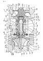
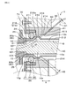
- FIG. 1 is a schematic cross-sectional view of a turbocharger bearing mechanism in Embodiment 1.
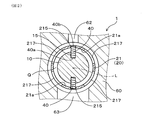
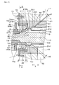
- FIG. FIG. 2 is a partially enlarged cross-sectional view taken along the line II-II in FIG. 1.
- FIG. 2 is an enlarged view of the vicinity of an oil film damper in a state where a rotating body assembly is rotated by 45 ° from the state of FIG. 1.
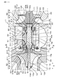
- FIG. 4 is a schematic cross-sectional view of a turbocharger bearing mechanism according to a second embodiment.
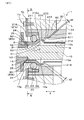
- FIG. 5 is a partially enlarged cross-sectional view taken along the line III-III in FIG. 4.
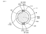
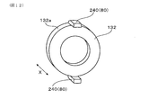
- FIG. 6 is a partially enlarged view of the cross section at the position of the IV-IV line in FIG. 5.
- FIG. 6 is an enlarged view of the vicinity of an oil film damper in Example 3.
- FIG. FIG. 6 is a schematic cross-sectional view of a turbocharger bearing mechanism according to a fourth embodiment.
- FIG. FIG. 6 is a partially enlarged view of the cross section corresponding to the position of the IV-IV line in FIG.
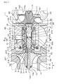
- FIG. FIG. 6 is a schematic cross-sectional view of a turbocharger bearing mechanism according to a fifth embodiment.
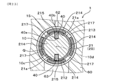
- FIG. 16 is a partially enlarged cross-sectional view taken along the line III-III in FIG. 15.
- FIG. The enlarged view of the cross-sectional schematic diagram of the oil film damper vicinity in the modification 1.
- FIG. The enlarged view of the cross-sectional schematic diagram of the oil film damper vicinity in the modification 2.
- FIG. 10 is a schematic cross-sectional view of a turbocharger bearing mechanism in Embodiment 6.
- FIG. 22 is a partially enlarged cross-sectional view taken along the line III-III in FIG. 21.
- the rotor shaft can be engaged with the inner ring via an engaging member.
- the inner ring can be reliably rotated with the rotor shaft via the engaging member.
- the inner ring may have an oil supply hole including a through hole, and at least a part of the oil may be supplied to the oil film damper through the oil supply hole.
- oil can be easily supplied to the oil film damper with a simple configuration.
- the inner ring is formed in a cylindrical shape extending along the axial direction of the rotor shaft, and the rotor shaft is provided with an end facing portion that faces the axial end of the inner ring in the axial direction, One of the axial end portion and the end facing portion is formed with a protruding portion protruding toward the other, and the other end of the axial end portion and the end facing portion is associated with the protruding portion.
- a mating engagement portion may be formed.
- the end of the inner ring in the axial direction and the end facing portion provided on the rotor shaft are engaged via the protrusion and the engaging portion, so that the inner ring is rotated along with the rotation of the rotor shaft. Goes around.
- edge part opposing part and the axial direction edge part are facing the axial direction, the protrusion part and the engaging part will be engaged in an axial direction.
- wheel can be engaged with a rotor shaft, without attaching a screw etc. to a rotor shaft in the direction which cross
- the end facing portion includes a turbine side end facing portion facing the axial end portion on the turbine impeller side, and a compressor side end facing portion facing the axial end portion on the compressor impeller side.
- the end facing portion may be formed at a joint portion of the rotor shaft with the turbine impeller, and the compressor side end facing portion may be formed on a collar on the compressor impeller side. In this case, since a separate member is not required for providing the end facing portion, the manufacturing cost can be reduced.
- At least one of the joint between the rotor shaft and the turbine impeller and the collar is provided with a plurality of oil slinger formed in a concave shape so as to scatter the oil flowing out from the oil film damper radially outward,
- the protrusion may be engaged with a part of the plurality of oil slinger, and a part of the oil slinger may constitute the engagement part.
- the oil slinger can be used as the engaging portion, it is not necessary to perform a separate member or processing, and the manufacturing cost can be reduced.
- the rotor shaft has a large diameter portion formed on the turbine shaft side, a small diameter portion formed on the compressor impeller side and having a diameter smaller than the diameter of the large diameter portion, the large diameter portion, and the above
- An annular member through which the small diameter portion is inserted is sandwiched between the step portion and the collar on the compressor impeller side.
- the end facing portion positioned on the compressor side may be formed.
- the inner ring may be configured to rotate with the rotation of the rotor shaft via the oil film damper.
- the friction in the oil film damper that is, the friction between the inner ring of the ball bearing and the rotor shaft
- the friction in the ball bearing that is, the friction between the inner ring and the outer ring. Therefore, when the rotor shaft rotates, a relative rotation occurs between the inner ring and the outer ring in the ball bearing, and the relative rotation between the inner ring and the rotor shaft in the oil film damper is suppressed. Relative rotation with the rotor shaft) occurs, but the inner ring can be rotated with the rotation of the rotor shaft only through the oil film damper.
- the fatigue strength of the rotor shaft can be improved as compared with the case where the screw hole machining is performed. And since the fatigue strength is improved, it is not necessary to increase the diameter of the rotor shaft. Therefore, the ball bearing can be reduced in size, and the contact area between the oil film damper and the ball bearing can be reduced. As a result, the viscous force generated between the two can be reduced, and the operation efficiency of the turbocharger can be improved. Moreover, it is not necessary to consider the loosening of the screw due to the high speed rotation of the rotor shaft.
- the inner ring is formed in a cylindrical shape extending along the axial direction of the rotor shaft, and the rotor shaft is provided with an end facing portion facing the axial end of the inner ring in the axial direction. It is preferable that at least one of the end portion and the end facing portion is formed with an oil discharge groove that is cut out so as to discharge the oil discharged from the oil film damper.
- the oil supplied to the oil film damper can be easily discharged from the oil film damper by the oil discharge groove, and the circulation of the oil in the housing is promoted. Thereby, the oil drainage property from an oil film damper can be improved, and the oil supply property to an oil film damper can be improved. As a result, it is possible to prevent the oil from filling the housing and leaking out of the housing.
- the turbocharger bearing mechanism it is effective to suppress the vibration of the rotating body assembly by the damping effect of the oil film damper in order to prevent the generation of abnormal noise and the decrease in operating efficiency.
- the oil lubricity is sufficiently high so that the oil is distributed throughout the oil film damper.
- the retainer circulates the oil and has an oil supply path that is inclined so as to approach the oil film damper as it approaches the rotor shaft, and the oil supply path passes the oil flowing through the oil supply path.
- An oil discharge port that discharges toward the inner ring is provided at an end on the inner ring side, and the inner ring is formed in a cylindrical shape and faces a discharge direction of oil discharged from the oil discharge port.
- a plurality of oil circulation holes are formed in the discharge port facing portion to distribute oil discharged from the oil discharge port to the inside of the inner ring and supply the oil film damper. can do.
- the oil supply path is inclined so as to approach the oil film damper as it approaches the rotor shaft, and the inner ring is opposed to the discharge port facing the oil discharge direction in the oil discharge port of the oil supply path.
- a plurality of oil circulation holes are formed in the part.
- the oil supply path may penetrate the retainer linearly, and the center line of the oil supply path may be orthogonal to the discharge port facing portion.
- the oil circulation hole opens in a surface perpendicular to the traveling direction of the oil discharged from the oil discharge port, the oil discharged from the oil discharge port easily flows into the oil circulation hole.
- the center line of the oil supply path means a virtual line passing through the center of the oil supply path and parallel to the penetration direction of the oil supply path in the retainer.
- the angle formed by the center line of the oil supply path and the axis of the rotor shaft is preferably 45 ° or less, and more preferably 30 ° or less.
- the oil lubricity of the oil film damper can be further improved, a sufficient damping effect can be obtained, and the generation of abnormal noise and the improvement of operating efficiency can be further achieved.
- the inner ring includes a damper forming portion that forms the oil film damper, and an oil storage portion that stores oil between the damper forming portion and the discharge port facing portion and the outer peripheral surface of the rotor shaft.
- the damper forming portion side wall surface of the reservoir forming portion is formed in a cross section including the axis of the rotor shaft and the center line of the oil supply passage. It may be formed in parallel with.
- the oil supplied to the oil reservoir through the oil circulation hole can be stored, and the oil flowing into the oil reservoir from the oil circulation hole can be stored in the damper forming part side.
- the oil film damper can be supplied along the wall surface. As a result, the lubricity is improved and the wedge effect is exhibited, so that a sufficient damping effect can be obtained in the oil film damper, and it is possible to further prevent the generation of abnormal noise and improve the operation efficiency. it can.
- the inner ring has a discharge portion forming portion that forms an oil discharge portion that discharges oil supplied to the oil film damper on the opposite side of the oil storage portion in the damper forming portion. It is preferable that an oil slinger that disperses the oil discharged from the oil discharge portion to the outside in the radial direction of the rotor shaft is provided at a position facing the portion.
- the oil supplied to the oil film damper is easily discharged from the oil film damper by the oil discharge portion and the oil slinger, and the circulation of the oil in the bearing housing is promoted. Thereby, the oil drainage property from an oil film damper can be improved, and the oil supply property to an oil film damper can be improved. As a result, it is possible to prevent oil from filling the bearing housing and leaking out of the bearing housing.
- the turbocharger bearing mechanism 1 of this example includes a rotor shaft 10, a ball bearing 20, and a housing 30.
- the rotor shaft 10 has a turbine impeller 11 attached to one end 10a and a compressor impeller 12 attached to the other end 10b.
- the ball bearing 20 includes an inner ring 21 and an outer ring 22 that are rotatably supported by each other.
- the rotor shaft 10 is engaged with the inner ring 21 via an engagement member 40.
- the housing 30 houses the rotor shaft 10, the ball bearing 20, and the engaging member 40 to constitute a bearing housing.
- the outer ring 22 is fixed to the housing 30 via a retainer 60, and an oil film damper 50 filled with oil is provided between the inner ring 21 and the outer peripheral surface 10c of the rotor shaft 10.
- a turbine impeller 11 is integrally provided at one end 10 a of the rotor shaft 10.
- the turbine impeller 11 is housed in the turbine housing 33, while the other end 10 b of the rotor shaft 10 is inserted through the collar 13 and the compressor impeller 12, and these are prevented from coming off by a shaft end nut 14.
- the compressor impeller 12 is accommodated in the compressor housing 34.
- a ball bearing 20 is provided between the turbine impeller 11 and the compressor impeller 12 in the rotor shaft 10.
- the ball bearing 20 has an inner ring 21 and an outer ring 22 as shown in FIG.
- the inner ring 21 has a substantially cylindrical shape.
- the inner diameter of the inner ring 21 is slightly larger than the outer diameter of the rotor shaft 10.
- the inner diameters of both end vicinity regions S in the axial direction X of the inner ring 21 are about 0.05 to 0.1 mm larger than the outer diameter of the rotor shaft 10, and both end vicinity regions S
- the inner diameter of the intermediate region T is larger than the inner diameter of the end vicinity region S.
- the rotor shaft 10 is inserted inside the inner ring 21.
- a gap P is formed in the region S near both ends between the inner ring 21 and the rotor shaft 10, and a gap Q wider than the gap P is formed in the intermediate region T.
- Both the gaps P and Q have a constant size in the circumferential direction in a stationary state where the center of the inner ring 21 and the center of the rotor shaft 10 are combined.
- a plurality of engaging member insertion holes 215 and oil supply holes 217 are formed in the central region 212 in the axial direction X of the inner ring 21 and arranged in the circumferential direction.
- the engagement member insertion holes 215 are provided at two positions symmetrical to the axis L of the rotor shaft 10, and the oil supply hole 217 is between the pair of engagement member insertion holes 215, and the rotor shaft A total of four places are provided at positions symmetrical to the ten axes.
- the engagement member insertion hole 215 and the oil supply hole 217 are both through holes, and the opening diameter of the oil supply hole 217 is larger than the opening diameter of the engagement member insertion hole 215. .
- an engagement member 40 made of a rod-like member having a diameter slightly smaller than the diameter of the engagement member insertion hole 215 is inserted into the engagement member insertion hole 215.
- a thread groove is formed at least on the side surface of the engagement member 40 on the one end 40 a side, and the engagement member 40 is screwed into a screw hole 15 formed in the rotor shaft 10 and attached to the rotor shaft 10.
- the protruding end portion 40 b on the other end side of the engaging member 40 protrudes outward in the radial direction of the rotor shaft 10, and is positioned radially outward from the inner side surface 21 a of the inner ring 21.
- the outer ring 22 of the ball bearing 20 has an annular shape. As shown in FIG. 1, two outer rings 22 are provided and face the outer peripheral surface (surface opposite to the surface facing the rotor shaft 10) in the region S in the vicinity of both ends in the axial direction X of the inner ring 21. Are arranged as shown. A ball-shaped rotor 23 is interposed between the inner ring 21 and the outer ring 22 via a cage (not shown). Thus, the inner ring 21 and the outer ring 22 are configured to be rotatable with respect to each other via the rotor 23 to form the ball bearing 20.
- the outer ring 22 is fixed to the housing 30 via the retainer 60, and the rotor shaft 10 is supported by the housing 30 via the ball bearing 20.
- the retainer 60 is formed with an oil supply path 62 for supplying oil around the ball bearing 20 and an oil discharge path 63 for discharging oil from around the ball bearing 20.
- the oil supply path 62 is formed in the retainer 60 on the upper side in the vertical direction of the housing 30, and the oil supply path 62 is provided with an oil discharge port 62 a that discharges oil around the ball bearing 20.
- the oil discharge port 62a is formed at a position overlapping with an oil supply hole 217 (see FIG. 3) formed in the inner ring 21 in the axial direction X.
- the oil discharge path 63 is formed on the lower side in the vertical direction of the housing 30, and an oil discharge port 63 b that opens to the outside of the housing 30 is formed below the oil discharge path 63.
- Oil film dampers 50 are respectively formed in gaps P formed between the inner ring 21 and the rotor shaft 10 in the region S in the vicinity of both ends of the inner ring 21.
- the oil film damper 50 in the state where the oil supply hole 217 is located immediately below the oil discharge port 62 a, the oil film damper 50 is configured such that a part of the oil supplied from the oil supply path 62 formed in the retainer 60 is an arrow.
- the gap is formed by entering between the inner ring 21 and the rotor shaft 10 via the oil supply hole 217 and reaching the gap P through the gap Q. Note that oil is sequentially supplied to the oil film damper 50 from the oil supply path 62, and the supplied oil is discharged from both end portions in the axial direction X of the inner ring 21.
- the rotor shaft 10 is assembled to the housing 30 as follows. First, the inner ring 21 of the ball bearing 20 is inserted into the retainer 60. And the rotor 23 and the outer ring
- one engaging member 40 is inserted from the oil supply passage 62 of the retainer 60 through the upper hole 31 of the housing 30 and is fastened and fixed to the screw hole 15 of the rotor shaft 10. Then, the other engagement member 40 is inserted from the oil discharge passage 63 of the retainer 60 through the lower hole 32 of the housing 30 and is fastened and fixed to the screw hole 15 of the rotor shaft 10. Finally, a stopper 64 is attached to the upper hole 31 of the housing 30 and the upper hole 31 is closed.
- the rotor shaft 10 (rotary body assembly 100) is rotated by 180 ° to be opposite to the screw hole 15 to which the one engagement member 40 is attached.
- the other engagement member 40 may be fastened and fixed to the screw hole 15 through the upper hole 31 so that the screw hole 15 located on the side is located immediately below the upper hole 31.
- the rotor shaft 10 is engaged with the inner ring 21 via the engagement member 40.
- the inner ring 21 can be reliably rotated with the rotor shaft 10 via the engaging member 40.
- the oil film damper 50 is formed between the inner ring 21 of the ball bearing 20 and the rotor shaft 10 (gap P)
- the rotor assembly 100 is connected to the rotor shaft 10 and the turbine impeller 11 attached to the rotor shaft 10.
- the compressor impeller 12 and an inner ring 21 that rotates with the rotor shaft 10 does not include a portion other than the inner ring 21 in the ball bearing 20 (outer ring 22, rotor 23, cage, etc.).
- the mass of the rotating body assembly 100 is relatively small. Further, since the outer diameter of the rotor shaft 10 is sufficiently smaller than the outer diameter of the outer ring 22 of the ball bearing 20, the contact area between the oil film damper 50 and the rotating body assembly 100 (the outer peripheral surface 10c of the rotor shaft 10) is compared. Is getting smaller. By these, the viscous force produced between the oil film damper 50 and the rotary body assembly 100 can be made comparatively small.
- the viscous force can be reduced, the force that hinders the rotating body assembly 100 from attempting to rotate the eccentric center of gravity is reduced, so that the rotating body assembly 100 can easily rotate even with a small amount of energy.
- the rotor shaft 10 rotates, it is possible to prevent the two impellers 11 and 12 provided at both ends of the rotor shaft 10 from swinging greatly. As a result, the generation of abnormal noise is prevented, and it is not necessary to increase the tip clearance between the impellers 11 and 12 and the respective housings 33 and 34, so that a reduction in operating efficiency can be prevented.
- the compressor housing 34 is provided with an abradable seal, the compressor impeller 12 is prevented from excessively contacting the abradable seal. Excessive wear is prevented.
- the oil damping effect on the rotating body assembly 100 can be effectively achieved by reducing the viscous force.
- the inner ring 21 has an oil supply hole 217 formed of a through hole, and at least a part of the oil is supplied between the inner ring 21 and the rotor shaft 10 (gap P) via the oil supply hole 217. It is configured. Therefore, the oil film damper 50 can be formed by supplying oil to the gap P with a simple configuration.
- the oil supply hole 217 is formed in the central region 212 of the inner ring 21 in the axial direction X.
- the oil supply hole 217 is not limited to this.
- a supply hole 217 may be formed.
- the turbocharger bearing mechanism 1 of this example includes a rotor shaft 10, a ball bearing 20, a retainer 60, and a housing 30.
- the rotor shaft 10 has a turbine impeller 11 attached to one end 10a and a compressor impeller 12 attached to the other end 10b.
- the ball bearing 20 includes an inner ring 21 and an outer ring 22 that are rotatably supported by each other.
- the retainer 60 holds the outer ring 22.
- the housing 30 houses the rotor shaft 10, the ball bearing 20, and the retainer 60, and constitutes a bearing housing.
- An oil film damper 50 is formed between the inner ring 21 and the outer peripheral surface 10c of the rotor shaft 10 with oil interposed in a film shape.
- the inner ring 21 is formed in a cylindrical shape extending along the axial direction X of the rotor shaft 10.
- the rotor shaft 10 is provided with end facing portions 80 that face the axial ends 21 b and 21 c of the inner ring 21 in the axial direction X.
- One of the axial end portions 21b and 21c and the end facing portion 80 is formed with a protruding portion 24 protruding toward the other, and the other is an engaging portion 25 with which the protruding portion 24 engages. Is formed.
- a turbine impeller 11 is integrally provided at one end 10 a of the rotor shaft 10.
- the turbine impeller 11 is accommodated in the turbine housing 33.
- the other end 10 b of the rotor shaft 10 is inserted through the collar 13 and the compressor impeller 12, and these are removed and stopped by a shaft end nut 14.
- the compressor impeller 12 is accommodated in the compressor housing 34.
- a housing 30 as a bearing housing for the rotor shaft 10 is provided between the turbine housing 33 and the compressor housing 34.
- a ball bearing 20 that supports the rotor shaft 10 is held in the housing 30 via a retainer 60.
- the retainer 60 is formed with an oil supply path 61 for supplying oil around the ball bearing 20 and an oil discharge path 63 for discharging oil from around the ball bearing 20.
- the oil supply path 61 is formed to be inclined so as to approach the oil film damper 50 as it approaches the rotor shaft 10.
- the oil supply path 61 passes through the retainer 60 linearly. Therefore, the center line L, which is an imaginary line passing through the center of the oil supply path 61 and parallel to the penetration direction of the oil supply path 61 in the retainer 60, is linear.
- the outlet of the oil supply path 61 (the end on the inner ring 21 side in the oil supply path 61) forms an oil discharge port 611 that is open so as to discharge the oil flowing through the oil supply path 61 toward the inner ring 21. .
- two oil supply paths 61 are provided so as to supply oil to each of the oil film dampers 50 formed at both ends in the axial direction X.
- the oil discharge path 63 is formed on the lower side in the vertical direction of the housing 30, and an oil discharge port 63 b that opens to the outside of the housing 30 is formed below the oil discharge path 63.
- An auxiliary oil supply path extending perpendicularly to the axial direction X may be formed between the two oil supply paths 61.
- the center line L of the oil supply path 61 is inclined with respect to the axis 10 d of the rotor shaft 10.
- the angle ⁇ formed by the center line L and the axis 10d is preferably 45 ° or less, more preferably 30 ° or less. In this example, ⁇ is 30 °.
- the ball bearing 20 has an inner ring 21 and an outer ring 22 as shown in FIG.
- the inner ring 21 has a substantially cylindrical shape.
- damper forming portions 211 that form the oil film damper 50 are formed between the outer peripheral surface 10 c of the rotor shaft 10.
- the inner diameter of the damper forming portion 211 is about 0.05 to 0.1 mm larger than the outer diameter of the rotor shaft 10.
- the central region 212 of the inner ring 21 in the axial direction X has an inner diameter larger than the inner diameter of the damper forming portion 211.
- the inner diameter of the central region 212 is larger than the outer diameter of the rotor shaft 10 by about 0.2 mm or more. Therefore, the clearance Q between the inner ring 21 and the outer peripheral surface 10c of the rotor shaft 10 in the central region 212 is the clearance P between the damper forming portion 211 and the outer peripheral surface 10c of the rotor shaft 10 (that is, the oil film damper 50). More than twice the thickness).
- Both the gaps P and Q have a constant size in the circumferential direction in a stationary state where the center of the inner ring 21 and the center of the rotor shaft 10 are combined.
- the discharge port facing portion 213 is formed at a position facing the discharge direction of the oil discharged from the oil discharge port 611 and is located between the damper forming portion 211 and the central region 212. ing. In this example, the discharge port facing portion 213 is orthogonal to the center line L.
- An oil circulation hole 214 is formed in the discharge port facing portion 213. As shown in FIG. 5, the oil circulation hole 214 is formed in parallel to the center line L of the oil supply path 61 in a cross section including the axis 10 d of the rotor shaft 10 and the center line L of the oil supply path 61. In this example, the opening width d2 of the oil circulation hole 214 is larger than the diameter d1 of the oil discharge port 611.
- a plurality of oil circulation holes 214 are formed and arranged at equal intervals in the circumferential direction. In this example, four oil circulation holes 214 are arranged at equal intervals in the circumferential direction.
- an oil storage portion that stores oil between the damper forming portion 211 and the discharge port facing portion 213 and the outer peripheral surface 10 c of the rotor shaft 10 in the axial direction X.
- a reservoir forming part 216 that forms 51 is formed.
- the reservoir forming part 216 has a diameter larger than that of the damper forming part 211, and the wall surface 216 a on the damper forming part 211 side is parallel to the center line L in the cross section including the axis 10 d and the center line L of the rotor shaft 10. Is formed.
- the oil supplied through the oil circulation hole 214 is supplied to the oil film damper 50 through the oil reservoir 51.
- a protruding portion 24 that protrudes in the axial direction X is formed at the axial end portion 21 b on the compressor impeller 12 side of the inner ring 21.
- a pair of protrusions 24 are provided in the diameter direction.
- the circumferential width of the protruding portion 24 is slightly narrower than the circumferential width of the engaging portion 25 described later.
- a protruding portion 24 that protrudes in the axial direction X is formed on the axial end portion 21 c of the inner ring 21 on the turbine impeller 11 side as well as on the compressor impeller 12 side.
- the rotor shaft 10 has a large diameter portion 10e on one end 10a side and a small diameter portion 10f on the other end 10b side.
- the small diameter portion 10f has a diameter smaller than the diameter of the large diameter portion 10e, and a step portion 10g is formed between the large diameter portion 10e and the small diameter portion 10f.
- the compressor impeller 12 is provided in the small-diameter portion 10f, and a collar 13 as an annular member is provided between the compressor impeller 12 and the stepped portion 10g.
- the collar 13 has an annular shape and is fixed to the small diameter portion 10 f by a shaft end nut 14. As shown in FIG.
- the collar 13 includes an end facing portion 80 (compressor side end facing portion 80b) facing the axial end portion 21b.
- a plurality of oil slinger 8 formed by notching the end facing portion 80 in a bay shape is formed in the end facing portion 80 at equal intervals in the circumferential direction.
- a pair of protrusion part 24 is engaging with a pair of oil slinger 8 mutually located in a diametrical direction among the some oil slinger 8, respectively. That is, the oil slinger 8 with which the protruding portion 24 engages forms the engaging portion 25.
- the rotor shaft 10 and the turbine impeller 11 are joined via an enlarged diameter portion 111 provided at one end 10 a of the rotor shaft 10.
- the enlarged diameter portion 111 is welded and fixed to one end 10 a of the rotor shaft 10.
- the enlarged diameter portion 111 is formed with an end facing portion 80 (a turbine side end facing portion 80 a) that faces the axial end portion 21 c of the inner ring 21.
- an oil slinger 8 is annularly formed in the entire circumferential direction at the turbine side end facing portion 80a.
- the oil slinger 8 is provided with a standing wall portion 81 erected outward in the radial direction.
- a pair of standing wall portions 81 are formed in the diameter direction.
- the standing wall portion 81 includes a first standing wall 81a and a second standing wall 81b.
- the first standing wall 81a and the second standing wall 81b are parallel to the axial direction X (see FIG. 4), and are separated in the circumferential direction by a distance substantially the same as the circumferential width of the protrusion 24.
- the projecting portion 24 is fitted between the first standing wall 81 a and the second standing wall 81 b, and the standing wall portion 81 forms the engaging portion 25.
- the protrusions 24 formed on the axial ends 21 b and 21 c of the inner ring 21 are engaged with the engaging portions 25 formed on the collar 13 and the enlarged diameter portion 111, respectively. It rotates with the rotation of the rotor shaft 10.
- the outer ring 22 of the ball bearing 20 has an annular shape. As shown in FIG. 4, two outer rings 22 are provided so as to face the outer peripheral surface (surface opposite to the surface facing the rotor shaft 10) in a region in the vicinity of both ends in the axial direction X of the inner ring 21. Respectively.
- a ball-shaped rotor 23 is interposed between the inner ring 21 and the outer ring 22 via a cage (not shown).
- the inner ring 21 and the outer ring 22 are configured to be rotatable with respect to each other via the rotor 23 to form the ball bearing 20.
- the outer ring 22 is fixed to the housing 30 via the retainer 60, and the rotor shaft 10 is supported by the housing 30 via the ball bearing 20.
- Oil film dampers 50 are respectively formed in the gaps P formed between the inner ring 21 and the rotor shaft 10 in the region in the vicinity of both ends of the inner ring 21 with oil interposed in the form of a film. As shown in FIG. 5, in a state where the oil circulation hole 214 of the inner ring 21 faces the oil discharge port 611, the oil film damper 50 receives the oil supplied from the oil supply path 61 formed in the retainer 60. It is formed by entering between the inner ring 21 and the rotor shaft 10 via the oil circulation hole 214 and reaching the gap P through the oil reservoir 51.
- the inner ring 21 has a discharge portion forming portion that forms an oil discharge portion 52 that discharges the oil supplied to the oil film damper 50 on the side opposite to the storage portion forming portion 216 in the damper forming portion 211. 218 is formed.
- the discharge portion forming portion 218 is separated from the outer peripheral surface 10c of the rotor shaft 10 at both end portions in the axial direction X of the inner ring 21, thereby allowing oil to pass between the discharge portion forming portion 218 and the outer peripheral surface 10c.
- An oil discharge portion 52 for discharging oil from the film damper 50 is formed.
- an oil slinger 8 formed in a concave shape is provided at a position facing the oil discharge portion 52 so that the oil discharged from the oil discharge portion 52 is scattered radially outward of the rotor shaft 10.
- the oil slinger 8 is formed in the collar 13 provided on the compressor impeller 12 side and the diameter-enlarged portion 111 of the turbine impeller 14, respectively.
- a plurality of oil slinger 8 is formed at equal intervals in the circumferential direction by notching the end 13 a of the collar 13 on the ball bearing 20 side in a bay shape.
- a plurality of oil slinger 8 is formed also in the enlarged diameter portion 111.
- the rotor shaft 10 is assembled to the housing 30 as follows. First, the inner ring 21 of the ball bearing 20 is inserted into the retainer 60. And the rotor 23 and the outer ring
- the components inside the oil film damper 50 are The rotor shaft 10, the turbine impeller 11 and the compressor impeller 12 attached to the rotor shaft 10, and an inner ring 21 that rotates with the rotor shaft 10, and parts other than the inner ring 21 in the ball bearing 20 on the parts inside the oil film damper 50 (Outer ring 22, rotor 23, cage, etc.) are not included. Therefore, the mass of the parts inside the oil film damper 50 is relatively small.
- the contact area between the oil film damper 50 and the outer peripheral surface 10c of the rotor shaft 10 is relatively small. Accordingly, the viscous force generated between the oil film damper 50 and the components inside the oil film damper 50 can be made relatively small.
- the viscous force can be reduced, the force that prevents the rotating assembly 100 constituted by the components inside the oil film damper 50 from rotating about the center of mass is reduced. 100 becomes easy to rotate eccentric gravity center.
- the rotor shaft 10 rotates, it is possible to prevent the two impellers 11 and 12 provided at both ends of the rotor shaft 10 from swinging greatly. As a result, the generation of abnormal noise is prevented and it is not necessary to increase the tip clearance between the impellers 11 and 12 and the respective housings 33 and 34, so that the operation efficiency can be improved.
- the compressor housing 34 is provided with an abradable seal, the compressor impeller 12 is prevented from excessively contacting the abradable seal. Excessive wear is prevented.
- the rotating body assembly 100 is easy to rotate with an eccentric center of gravity, the adjustment of the mass balance of the rotating body assembly 100 does not require a very high accuracy, so that the adjustment of the mass balance is facilitated and the manufacturing is performed. Cost can be reduced.
- the oil damping effect on the rotating body assembly 100 can be effectively achieved by reducing the viscous force.
- the axial ends 21 b and 21 c of the inner ring 21 and the end facing portion 80 provided on the rotor shaft 10 are engaged via the protruding portion 24 and the engaging portion 25, so that the rotor shaft 10.
- the inner ring 21 is reliably rotated.
- the edge part opposing part 80 and the axial direction edge parts 21b and 21c are facing the axial direction X, the protrusion part 24 and the engaging part 25 will be engaged in the axial direction X.
- FIG. Therefore, the inner ring 21 can be engaged with the rotor shaft 10 without attaching a screw or the like to the rotor shaft 10 in a direction crossing the axial direction X. For this reason, since it is not necessary to perform screw hole processing or the like on the rotor shaft 10, it is easy to adjust the mass balance of the rotating body assembly 100, and the manufacturing cost can be reduced.
- the fatigue strength of the rotor shaft 10 can be improved as compared with the case where the screw hole machining is performed. Since the fatigue strength is improved, the diameter of the rotor shaft 10 does not need to be increased, so that the ball bearing 20 can be reduced in size, and the contact area between the oil film damper 50 and the ball bearing 20 can be reduced. As a result, the viscous force generated between the two can be reduced, and the operation efficiency of the turbocharger 1 can be improved. Further, it is not necessary to consider the loosening of the screw due to the high speed rotation of the rotor shaft 10.
- the end facing portion 80 includes a turbine side end facing portion 80a facing the axial end 21c on the turbine impeller 11 side and a compressor side facing the axial end 21b on the compressor impeller 12 side. It consists of an end facing part 80b.
- the turbine-side end facing portion 80 a is formed in the diameter-expanded portion 111 that is a joint portion between the rotor shaft 10 and the turbine impeller 11.
- the compressor side end facing portion 80b is formed in the collar 13 on the compressor impeller 12 side.
- the enlarged diameter portion 111 and the collar 13 are provided with a plurality of oil slinger 8 formed in a concave shape so as to scatter oil flowing out from the oil film damper 50 outward in the radial direction.
- the part 24 is engaged with a part of the plurality of oil slinger 8, and a part of the oil slinger 8 constitutes the engaging part 25.
- a plurality of oil slinger 8 formed in a concave shape is formed in the end facing portion 80, and the protruding portion 24 engages with a part of the plurality of oil slinger 8, and the oil slinger 8 A part of the portion constitutes the engaging portion 25.
- the projecting portion 24 and the engaging portion 25 are provided on both the compressor impeller 12 side and the turbine impeller 11 side.
- the present invention is not limited thereto, and is provided on one of the compressor impeller 12 side and the turbine impeller 11 side. It is good as well. In this case, the manufacturing cost can be reduced as compared with the case where both are provided.
- the protrusion part 24 and the engaging part 25 are good also as providing in one place, it is preferable to provide in a diametrical direction a pair, ie, two places, like this example. This is because it is easy to adjust the mass balance of the rotating body assembly 100. Therefore, it is most preferable to provide a pair of the projecting portion 24 and the engaging portion 25 in the diametrical direction on one side of the compressor impeller 12 and the turbine impeller 11 side.
- the turbocharger bearing mechanism 1 that can prevent the generation of abnormal noise, improve the operation efficiency, and reduce the manufacturing cost.
- the turbocharger bearing mechanism 1 of this example employs an annular member 131 as shown in FIGS. 9 and 10 instead of the collar 13 (see FIG. 4) in the second embodiment as the annular member.
- the rotor shaft 10 is formed on the large-diameter portion 10e formed on the turbine shaft 11 side and the compressor impeller 12 side, and on the large-diameter portion 10e. It has a small diameter portion 10f having a diameter smaller than the diameter, and a step portion 10g formed between the large diameter portion 10e and the small diameter portion 10f.
- the small-diameter portion 10f is inserted into the annular member 131 and is sandwiched between the collar 13 and the step portion 10g that are shrink-fitted into the small-diameter portion 10f.
- the annular member 131 is formed with a pair of concave engaging portions 25 in the diametrical direction from the outer edge 131 a toward the inside, as shown in FIG. 10.
- symbol is attached
- the turbocharger bearing mechanism 1 of the present example by providing the annular member 131 separately from the collar 13, processing for forming the engaging portion 25 is facilitated and the engaging portion 25 is configured with a simple configuration. Since it can be formed, the manufacturing cost can be reduced. In the case of this example, the same operational effects as in the case of the second embodiment are obtained except for the operational effects of forming the engaging portion 25 in the collar 13.
- Example 4 In the turbocharger bearing mechanism 1 of this example, instead of the projecting portion 24 and the engaging portion 25 (see FIGS. 4 to 7) in the second embodiment, the projecting portion 240 and the engaging portion 250 shown in FIGS. 11 to 13 are used. Is provided. As shown in FIG. 11, the protrusion 240 provided on the compressor impeller 12 side is formed on the annular member 132. Similar to the annular member 131 (see FIG. 9) in the third embodiment, the annular member 132 is sandwiched between the collar 13 and the step portion 10f. As shown in FIG. 12, the annular member 132 has a pair of protruding portions 240 formed in the diameter direction. The protruding portion 240 protrudes radially outward from the outer edge 132a of the annular member 132, and is bent toward the inner ring 21 as shown in FIG.
- the enlarged diameter portion 111 is formed with a protruding portion 240 provided on the turbine impeller 11 side.
- a pair of the projecting portions 240 are formed in the diameter direction so as to extend in a rib shape toward the inner ring 21.
- an engagement portion 250 formed in a concave shape is formed at the axial end portion 21 b of the inner ring 21.
- a pair of engaging portions 250 are formed in the diameter direction.
- a pair of engaging portions 250 is formed in the diametrical direction at the axial end portion 21 c of the inner ring 21.
- the engaging portions 250 are provided on both the axial ends 21b and 21c of the inner ring 21, but the engaging portions are provided on either of the axial ends 21b and 21c. 250 (see FIG. 14) may be formed, and the protrusion 24 (see FIG. 8) in the second embodiment may be formed on the other side.
- the annular member 132 see FIG. 12
- the enlarged-diameter portion 111 in which the projecting portion 240 that engages with the engaging portion 250 (see FIG. 14) is formed, and the projecting portion 24 are engaged.
- Engaging engagement portions 25 are formed. Even in these cases, the above-described effects can be obtained.
- the turbocharger bearing mechanism 1 of this example includes a rotor shaft 10, a ball bearing 20, a retainer 60, and a housing 30.
- the rotor shaft 10 has a turbine impeller 11 attached to one end 10a and a compressor impeller 12 attached to the other end 10b.
- the ball bearing 20 includes an inner ring 21 and an outer ring 22 that are rotatably supported relative to each other.
- the retainer 60 holds the outer ring 22.
- the housing 30 houses the rotor shaft 10, the ball bearing 20, and the retainer 60, and constitutes a bearing housing.
- An oil film damper 50 is formed between the inner ring 21 and the outer peripheral surface 10c of the rotor shaft 10 with oil interposed in the form of a film.
- the inner ring 21 is configured to rotate with the rotation of the rotor shaft 10 via the oil film damper 50.
- a turbine impeller 11 is integrally provided at one end 10 a of the rotor shaft 10.
- the turbine impeller 11 is accommodated in the turbine housing 33.
- the other end 10 b of the rotor shaft 10 is inserted through the collar 13 and the compressor impeller 12, and these are removed and stopped by a shaft end nut 14.
- the compressor impeller 12 is accommodated in the compressor housing 34.
- a housing 30 as a bearing housing for the rotor shaft 10 is provided between the turbine housing 33 and the compressor housing 34.
- a ball bearing 20 that supports the rotor shaft 10 is held in the housing 30 via a retainer 60.
- the retainer 60 is formed with an oil supply path 61 for supplying oil around the ball bearing 20 and an oil discharge path 63 for discharging oil from around the ball bearing 20.
- the oil supply path 61 is formed to be inclined so as to approach the oil film damper 50 as it approaches the rotor shaft 10.
- the oil supply path 61 passes through the retainer 60 linearly. Therefore, the center line L, which is an imaginary line passing through the center of the oil supply path 61 and parallel to the penetration direction of the oil supply path 61 in the retainer 60, is linear.
- the outlet of the oil supply path 61 (the end on the inner ring 21 side in the oil supply path 61) forms an oil discharge port 611 that is open so as to discharge the oil flowing through the oil supply path 61 toward the inner ring 21. .
- two oil supply paths 61 are provided so as to supply oil to each of the oil film dampers 50 formed at both ends in the axial direction X.
- the oil discharge path 63 is formed on the lower side in the vertical direction of the housing 30, and an oil discharge port 63 b that opens to the outside of the housing 30 is formed below the oil discharge path 63.
- An auxiliary oil supply path extending perpendicularly to the axial direction X may be formed between the two oil supply paths 61.
- the center line L of the oil supply path 61 is inclined with respect to the axial center 10d of the rotor shaft 10.
- the angle ⁇ formed by the center line L and the axis 10d is preferably 45 ° or less, more preferably 30 ° or less. In this example, ⁇ is 30 °.
- the ball bearing 20 has an inner ring 21 and an outer ring 22 as shown in FIG.
- the inner ring 21 has a substantially cylindrical shape.
- damper forming portions 211 that form the oil film damper 50 are formed between the outer peripheral surface 10 c of the rotor shaft 10.
- the inner diameter of the damper forming portion 211 is about 0.05 to 0.1 mm larger than the outer diameter of the rotor shaft 10.
- the central region 212 of the inner ring 21 in the axial direction X has an inner diameter larger than the inner diameter of the damper forming portion 211.
- the inner diameter of the central region 212 is larger than the outer diameter of the rotor shaft 10 by about 0.2 mm or more. Therefore, the clearance Q between the inner ring 21 and the outer peripheral surface 10c of the rotor shaft 10 in the central region 212 is the clearance P between the damper forming portion 211 and the outer peripheral surface 10c of the rotor shaft 10 (that is, the oil film damper 50). More than twice the thickness).
- Both the gaps P and Q have a constant size in the circumferential direction in a stationary state where the center of the inner ring 21 and the center of the rotor shaft 10 are combined.
- the discharge port facing portion 213 is formed at a position facing the discharge direction of the oil discharged from the oil discharge port 611 and is positioned between the damper forming portion 211 and the central region 212. ing. In this example, the discharge port facing portion 213 is orthogonal to the center line L.
- An oil circulation hole 214 is formed in the discharge port facing portion 213. As shown in FIG. 16, the oil circulation hole 214 is formed on the center line L of the oil supply path 61 in a cross section including the axis 10 d of the rotor shaft 10 and the center line L of the oil supply path 61. In this example, the opening width d2 of the oil circulation hole 214 is larger than the diameter d1 of the oil discharge port 611. A plurality of oil circulation holes 214 are formed and arranged at equal intervals in the circumferential direction. In this example, four oil circulation holes 214 are arranged at equal intervals in the circumferential direction.
- an oil storage portion that stores oil between the damper forming portion 211 and the discharge port facing portion 213 and the outer peripheral surface 10 c of the rotor shaft 10.
- a reservoir forming part 216 that forms 51 is formed.
- the reservoir forming part 216 has a diameter larger than that of the damper forming part 211, and the wall surface 216 a on the damper forming part 211 side is parallel to the center line L in the cross section including the axis 10 d and the center line L of the rotor shaft 10. Is formed.
- the oil supplied through the oil circulation hole 214 is supplied to the oil film damper 50 through the oil reservoir 51.
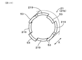
- an oil discharge groove 219 that is notched and formed in a concave shape is formed in the axial end portion 21b of the inner ring 21 on the compressor impeller 12 side.
- two pairs of oil discharge portions 219 are provided in the diameter direction of the inner ring 21.
- the oil discharge groove 219 forms an oil discharge portion 52 together with a discharge portion forming portion 218 described later.
- an oil discharge groove 219 that is notched and formed in a concave shape in the axial end portion 21 c on the turbine impeller 11 side of the inner ring 21 is formed in the same manner as the compressor impeller 12 side.
- an end facing portion 80 (compressor side end facing portion) of the collar 13 described later is provided at the axial end 21b of the inner ring 21 on the compressor impeller 12 side, between the adjacent oil discharge grooves 219.
- a facing surface 53 is formed opposite to 80b).
- the axial end 21c on the turbine impeller 11 side of the inner ring 21 also faces an end facing portion 80 (a turbine side end facing portion 80a) in the enlarged diameter portion 111 described later between adjacent oil discharge grooves 219.
- a facing surface 53 is formed.
- the thrust shaft 10 is positioned in the thrust direction (that is, the axial direction X).
- the rotor shaft 10 has a large diameter portion 10e on one end 10a side and a small diameter portion 10f on the other end 10b side.
- the small diameter portion 10f has a diameter smaller than the diameter of the large diameter portion 10e, and a step portion 10g is formed between the large diameter portion 10e and the small diameter portion 10f.
- the compressor impeller 12 is provided in the small-diameter portion 10f, and a collar 13 as an annular member is provided between the compressor impeller 12 and the stepped portion 10g.
- the collar 13 has an annular shape and is fixed to the small diameter portion 10 f by a shaft end nut 14. As shown in FIG.
- the collar 13 includes an end facing portion 80 (compressor side end facing portion 80b) facing the facing surface 53 of the axial end portion 21b.
- a plurality of oil slinger 8 formed by notching the end facing portion 80 in a bay shape is formed in the end facing portion 80 at equal intervals in the circumferential direction. Yes.
- the rotor shaft 10 and the turbine impeller 11 are joined via an enlarged diameter portion 111 provided at one end 10 a of the rotor shaft 10.
- the enlarged diameter portion 111 is welded and fixed to one end 10 a of the rotor shaft 10.
- the enlarged diameter portion 111 is formed with an end facing portion 80 (turbine side end facing portion 80 a) that faces the facing surface 53 of the axial end portion 21 c of the inner ring 21.
- the outer ring 22 of the ball bearing 20 has an annular shape. As shown in FIG. 15, two outer rings 22 are provided so as to face the outer peripheral surface (surface opposite to the surface facing the rotor shaft 10) in a region near both ends in the axial direction X of the inner ring 21. Respectively.
- a ball-shaped rotor 23 is interposed between the inner ring 21 and the outer ring 22 via a cage (not shown).
- the inner ring 21 and the outer ring 22 are configured to be relatively rotatable via the rotor 23 to form the ball bearing 20.
- the outer ring 22 is fixed to the housing 30 via a retainer 60, and the rotor shaft 10 is disposed on the housing 30 via a ball bearing 20.
- Oil film dampers 50 are respectively formed in the gaps P formed between the inner ring 21 and the rotor shaft 10 in the region in the vicinity of both ends of the inner ring 21 with oil interposed in the form of a film. As shown in FIG. 16, in a state where the oil circulation hole 214 of the inner ring 21 faces the oil discharge port 611, the oil film damper 50 receives the oil supplied from the oil supply path 61 formed in the retainer 60. It is formed by entering between the inner ring 21 and the rotor shaft 10 via the oil circulation hole 214 and reaching the gap P through the oil reservoir 51.
- the inner ring 21 has a discharge portion forming portion 218 that forms the oil discharge portion 52 together with the oil discharge groove 219 on the opposite side of the damper forming portion 211 from the storage portion forming portion 216. ing.
- the discharge portion forming portion 218 is separated from the outer peripheral surface 10c of the rotor shaft 10 at both end portions in the axial direction X of the inner ring 21, thereby allowing oil to pass between the discharge portion forming portion 218 and the outer peripheral surface 10c.
- An oil discharge portion 52 for discharging oil from the film damper 50 is formed.
- an oil slinger 8 formed in a concave shape is provided at a position facing the oil discharge portion 52 so that the oil discharged from the oil discharge portion 52 is scattered radially outward of the rotor shaft 10.
- the oil slinger 8 is formed in a collar 13 provided on the compressor impeller 12 side and a diameter-expanded portion 111 of the turbine impeller 11, respectively.
- the end portions 13a of the collar 13 on the ball bearing 20 side of the collar 13 are cut out in a bay shape, and a plurality of oil slinger 8 are formed at equal intervals in the circumferential direction as shown in FIG.
- a plurality of oil slinger 8 is formed also in the enlarged diameter portion 111.
- the rotor shaft 10 is assembled to the housing 30 as follows. First, the inner ring 21 of the ball bearing 20 is inserted into the retainer 60. And the rotor 23 and the outer ring
- the components inside the oil film damper 50 are The rotor shaft 10, the turbine impeller 11 and the compressor impeller 12 attached to the rotor shaft 10, and an inner ring 21 that rotates with the rotor shaft 10, and parts other than the inner ring 21 in the ball bearing 20 on the parts inside the oil film damper 50 (Outer ring 22, rotor 23, cage, etc.) are not included. Therefore, the (inertia) mass of the components inside the oil film damper 50 is relatively small.
- the contact area between the oil film damper 50 and the outer peripheral surface 10c of the rotor shaft 10 is relatively small. Accordingly, the viscous force generated between the oil film damper 50 and the components inside the oil film damper 50 can be made relatively small.
- the viscous force can be reduced, the force that prevents the rotating body assembly 100 constituted by the components inside the oil film damper 50 from rotating about the center of mass is reduced. Since the (inertia) mass of the inner part is relatively small, the rotating body assembly 100 can easily rotate eccentrically with a small amount of energy. As a result, when the rotor shaft 10 rotates, it is possible to prevent the two impellers 11 and 12 provided at both ends of the rotor shaft 10 from swinging greatly. As a result, the generation of abnormal noise is prevented and it is not necessary to increase the tip clearance between the impellers 11 and 12 and the respective housings 33 and 34, so that the operation efficiency can be improved.
- the compressor impeller 12 When the compressor housing 34 is provided with an abradable seal, the compressor impeller 12 is prevented from excessively contacting the abradable seal. Excessive wear is prevented. Further, as described above, since the rotating body assembly 100 is easy to rotate with an eccentric center of gravity, the adjustment of the mass balance of the rotating body assembly 100 does not require a very high accuracy, so that the adjustment of the mass balance is facilitated and the manufacturing is performed. Cost can be reduced.
- the oil damping effect on the rotating body assembly 100 can be effectively achieved by reducing the viscous force.
- the inner ring 21 is configured to rotate with the rotation of the rotor shaft 10 via the oil film damper 50.
- the friction in the oil film damper 50 that is, the friction between the inner ring 21 and the rotor shaft 10
- the friction in the ball bearing 20 that is, the friction between the inner ring 21 and the outer ring 22.
- the fatigue strength of the rotor shaft 10 can be improved as compared with the case where the screw hole machining is performed. Since the fatigue strength is improved, the diameter of the rotor shaft 10 does not need to be increased, so that the ball bearing 20 can be reduced in size, and the contact area between the oil film damper 50 and the ball bearing 20 can be reduced. As a result, the viscous force generated between the two can be reduced, and the operation efficiency of the turbocharger 1 can be improved. Further, it is not necessary to consider the loosening of the screw due to the high speed rotation of the rotor shaft 10.
- the inner ring 21 is formed in a cylindrical shape extending along the axial direction X of the rotor shaft 10, and the rotor shaft 10 faces the axial ends 21 b and 21 c of the inner ring 21 in the axial direction X.
- An end facing portion 80 is provided.
- the oil discharge groove 219 is cut out at least one of the axial end portions 21b and 21c and the end facing portion 80 (both in this example) so as to discharge the oil discharged from the oil film damper 50. Is formed. Accordingly, the oil supplied to the oil film damper 50 can be easily discharged from the oil film damper 50 by the oil discharge groove 219, and the circulation of the oil in the housing 30 is promoted. And the oil drainage property from the oil film damper 50 improves, and the oil supply property to the oil film damper 50 improves. As a result, it is possible to prevent the oil from filling the housing 30 and leaking out of the housing 30.
- the oil discharge grooves 219 may be provided in one place, but a pair in the diametrical direction such as a pair in the diametrical direction or two pairs in the diametrical direction of the inner ring 21 as in this example. It is preferable to provide a plurality of them. This is because it is easy to adjust the weight balance of the rotating body assembly 100.
- the oil drain from the oil film damper 50 is not necessarily limited to the formation of both the oil drain groove 219 and the oil slinger 8 as long as the required oil drainability is ensured. It is sufficient that at least one of the two is formed.
- the oil discharge groove 219 may not be formed, and the oil slinger 8 may be formed.
- the oil supplied to the oil film damper 50 is discharged toward the oil slinger 8 through the discharge portion forming portion 218 formed at the axial end portion 21 b of the inner ring 21, and the oil slinger 8
- the rotor shaft 10 is scattered outside in the radial direction. Thereby, the required oil draining property is securable.
- the oil supplied to the oil film damper 50 is radially outside of the rotor shaft 10 via the discharge portion forming portion 218 and the oil discharge groove 219 formed at the axial end portion 21 b of the inner ring 21. Is scattered. Thereby, the required oil draining property is securable.
- the turbocharger bearing mechanism 1 that can prevent the generation of abnormal noise, improve the operation efficiency, and reduce the manufacturing cost.
- Example 6 A turbocharger bearing mechanism 1 according to a sixth embodiment will be described with reference to FIGS.
- members equivalent to those in the above-described embodiment are denoted by the same reference numerals and description thereof is omitted unless otherwise described.
- the retainer 60 is formed with both an oil supply path 61 for supplying oil around the ball bearing 20 and an auxiliary oil supply path 62.
- the oil supply paths 61 are provided at two locations so as to supply oil to each of the oil film dampers 50 formed at both ends in the axial direction X.
- the auxiliary oil supply path 62 is formed between the two oil supply paths 61. 21 and 23, the auxiliary oil supply path 62 is formed in the same manner as the oil supply path 62 (see FIGS. 1 and 2) in the first embodiment.
- the same effects as those of the first embodiment can be obtained. Further, in the first embodiment, as shown in FIGS. 1 and 3, the oil supply passage 62 and the engagement member insertion hole 215 and the oil supply hole 217 formed in the central region 212 in the axial direction X of the inner ring 21 are interposed. In this example, in addition to this, oil is supplied to the inside of the inner ring 21 mainly through the oil supply path 61 and the oil circulation hole 214. Are configured to supply.
- the oil supply path 61 is formed so as to be closer to the oil film damper 50 as it approaches the rotor shaft 10, and the oil discharge direction (see FIG.
- the oil supply path 61 passes through the retainer 60 in a straight line, and the center line L of the oil supply path 61 is orthogonal to the discharge port facing portion 213.
- the oil circulation hole 214 opens in a plane perpendicular to the traveling direction of the oil discharged from the oil discharge port 611, and therefore, the oil discharged from the oil discharge port 611 easily flows into the oil circulation hole 214.
- the supply of oil to the oil film damper 50 is promoted, the oil lubricity of the oil film damper 50 is further improved, and a more sufficient damping effect can be obtained. Can be further improved.
- the oil circulation hole 214 is formed in parallel to the center line L in the cross section including the axis 10 d of the rotor shaft 10 and the center line L of the oil supply path 61.
- the traveling direction of the oil discharged from the oil discharge port 611 coincides with the formation direction of the oil circulation hole 214, so that the oil flowing into the oil circulation hole 214 reaches the oil film damper 50 inside the inner ring 21. It has become easier.
- the angle ⁇ formed by the center line L of the oil supply passage 61 and the axis 10d of the rotor shaft 10 is preferably 45 ° or less, more preferably 30 ° or less, and in this example, 30 °. Yes.
- the oil discharged from the oil discharge port 611 through the oil supply passage 61 advances toward the oil film damper 50 inside the inner ring 21 and is actively injected into the oil film damper 50. Therefore, the lubricity of oil in the oil film damper 50 is improved, a sufficient damping effect can be obtained, and the generation of abnormal noise can be prevented and the operation efficiency can be further improved.
- oil is applied to the inner ring 21 between the damper forming portion 211 that forms the oil film damper 50, between the damper forming portion 211 and the discharge port facing portion 213, and the outer peripheral surface 10 c of the rotor shaft 50.
- a storage portion forming portion 216 that forms the oil storage portion 51 to be stored is provided, and a wall surface 216a on the damper forming portion 211 side in the storage portion forming portion 216 is connected to the axis 10d of the rotor shaft 10 and the oil supply path 61.
- the cross section including the center line L is formed in parallel to the center line L.
- the oil supplied to the oil storage part 51 through the oil circulation hole 214 can be stored, and the oil stored in the oil storage part 51 by the oil flowing into the oil storage part 51 from the oil circulation hole 24.
- Oil can be supplied to the oil film damper 50 along the wall surface 216a on the damper forming portion 211 side.
- the oil stored in the oil storage section 51 is positively supplied to the oil film damper 50 due to the wedge effect, so that a sufficient damping effect can be obtained in the oil film damper 50, and noise is generated. Prevention and improvement of driving efficiency can be further achieved.
- the inner ring 21 has a discharge portion forming portion 218 that forms an oil discharge portion 52 that discharges oil supplied to the oil film damper 50 on the opposite side of the oil storage portion 61 in the damper forming portion 211.
- An oil slinger 8 that is formed and that disperses the oil discharged from the oil discharge portion 52 outward in the radial direction of the rotor shaft 10 is provided at a position facing the oil discharge portion 52.
- the auxiliary oil supply path 62 is provided in the retainer 60, the auxiliary oil supply hole 217 is provided in the inner ring 21, and oil is supplied from the central region 212 to the inner side of the inner ring 21, but the oil supply path 61 and When sufficient oil can be supplied to the oil film damper 50 through the oil circulation hole 214, the auxiliary oil supply path 62 and the auxiliary oil supply hole 217 may not be provided.
- turbocharger bearing mechanism 1 that can prevent the generation of abnormal noise, improve the operation efficiency, and reduce the manufacturing cost.
Landscapes
- Engineering & Computer Science (AREA)
- General Engineering & Computer Science (AREA)
- Mechanical Engineering (AREA)
- Chemical & Material Sciences (AREA)
- Combustion & Propulsion (AREA)
- Supercharger (AREA)
- Support Of The Bearing (AREA)
Abstract
La présente invention vise à procurer un mécanisme de palier (1) pour un turbocompresseur, avec lequel des sons anormaux et des réductions du rendement de fonctionnement sont empêchés, et des coûts de fabrication peuvent être réduits. A cet effet, l'invention porte sur un mécanisme de palier (1) pour un turbocompresseur, lequel mécanisme comporte un arbre de rotor (10), des roulements à billes (20), un dispositif de maintien (60) et un boîtier (30). L'arbre de rotor (10) comprend une hélice de turbine (10) fixée à une extrémité (10a), et une hélice de compresseur (12) fixée à l'autre extrémité (10b). Les roulements à billes (20) comportent une bague interne (21) et une bague externe (22) supportées de façon à être aptes à tourner l'une par rapport à l'autre. Le dispositif de maintien (60) supporte la bague externe (22). De l'huile sous forme de film est interposée entre la bague interne (21) et la surface périphérique externe (10c) de l'arbre de rotor (10), ce qui forme un amortisseur à film d'huile (50).
Priority Applications (3)
| Application Number | Priority Date | Filing Date | Title |
|---|---|---|---|
| EP15841544.8A EP3176404A4 (fr) | 2014-09-18 | 2015-09-17 | Mécanisme de palier pour turbocompresseur |
| US15/511,991 US20170298769A1 (en) | 2014-09-18 | 2015-09-17 | Bearing structure of turbocharger |
| CN201580039298.XA CN106536892A (zh) | 2014-09-18 | 2015-09-17 | 涡轮增压器用轴承机构 |
Applications Claiming Priority (8)
| Application Number | Priority Date | Filing Date | Title |
|---|---|---|---|
| JP2014190131A JP2016061381A (ja) | 2014-09-18 | 2014-09-18 | ターボチャージャ用軸受機構 |
| JP2014-190131 | 2014-09-18 | ||
| JP2014252155A JP2016113934A (ja) | 2014-12-12 | 2014-12-12 | ターボチャージャ用軸受機構 |
| JP2014252158A JP2016113937A (ja) | 2014-12-12 | 2014-12-12 | ターボチャージャ用軸受機構 |
| JP2014-252155 | 2014-12-12 | ||
| JP2014-252158 | 2014-12-12 | ||
| JP2015-162246 | 2015-08-19 | ||
| JP2015162246A JP2017040203A (ja) | 2015-08-19 | 2015-08-19 | ターボチャージャ用軸受機構 |
Publications (1)
| Publication Number | Publication Date |
|---|---|
| WO2016043293A1 true WO2016043293A1 (fr) | 2016-03-24 |
Family
ID=55533329
Family Applications (1)
| Application Number | Title | Priority Date | Filing Date |
|---|---|---|---|
| PCT/JP2015/076575 WO2016043293A1 (fr) | 2014-09-18 | 2015-09-17 | Mécanisme de palier pour turbocompresseur |
Country Status (4)
| Country | Link |
|---|---|
| US (1) | US20170298769A1 (fr) |
| EP (1) | EP3176404A4 (fr) |
| CN (1) | CN106536892A (fr) |
| WO (1) | WO2016043293A1 (fr) |
Cited By (3)
| Publication number | Priority date | Publication date | Assignee | Title |
|---|---|---|---|---|
| EP3258126A1 (fr) * | 2016-04-06 | 2017-12-20 | OTICS Corporation | Ensemble de roulement de turbocompresseur à gaz d'échappement avec amortisseur à film d'huile comprimée |
| EP3260717A1 (fr) * | 2016-05-20 | 2017-12-27 | OTICS Corporation | Ensemble de roulement de turbocompresseur à gaz d'échappement avec amortisseur à film d'huile comprimée |
| CN112229612A (zh) * | 2020-09-29 | 2021-01-15 | 南京航空航天大学 | 一种挤压油膜阻尼器-转子试验系统油膜静偏心加载装置及加载方法 |
Families Citing this family (10)
| Publication number | Priority date | Publication date | Assignee | Title |
|---|---|---|---|---|
| ITUA20162733A1 (it) * | 2016-04-20 | 2017-10-20 | Ge Avio Srl | Unita' di trasferimento d'olio per trasferire olio tra una parte statica ed una parte rotante |
| US10677253B2 (en) * | 2016-12-12 | 2020-06-09 | Garrett Transportation I Inc. | Turbocharger assembly |
| CN107269397B (zh) * | 2017-08-18 | 2019-05-21 | 中国科学院工程热物理研究所 | 一种轻质轴承座结构 |
| DE102017216282A1 (de) * | 2017-09-14 | 2019-03-14 | Continental Automotive Gmbh | Turboladereinrichtung mit offenem Federring zum Halten einer Lagerhülse |
| US10753281B2 (en) * | 2017-11-21 | 2020-08-25 | Raytheon Technologies Corporation | Ablatable shaft feature in a gas turbine engine |
| JP6510096B1 (ja) | 2018-02-08 | 2019-05-08 | 三菱重工業株式会社 | 過給機 |
| US10495144B1 (en) * | 2018-05-25 | 2019-12-03 | Borgwarner Inc. | Single-row ball bearing with integrated squeeze-film damper |
| CN109707467B (zh) * | 2018-11-30 | 2022-02-11 | 江苏理工学院 | 一种防积碳涡轮增压器 |
| JP7146353B2 (ja) * | 2018-12-25 | 2022-10-04 | 東芝三菱電機産業システム株式会社 | 軸受装置 |
| CN114233609A (zh) * | 2021-12-08 | 2022-03-25 | 珠海格力电器股份有限公司 | 轴承冷却结构及轴承及压缩机及制冷设备 |
Citations (3)
| Publication number | Priority date | Publication date | Assignee | Title |
|---|---|---|---|---|
| JP2002129967A (ja) * | 2000-10-24 | 2002-05-09 | Nsk Ltd | ターボチャージャ用回転支持装置 |
| JP4424874B2 (ja) * | 2001-05-02 | 2010-03-03 | 株式会社日本自動車部品総合研究所 | ターボチャージャの潤滑装置 |
| JP2013245663A (ja) * | 2012-05-29 | 2013-12-09 | Ihi Corp | 過給機 |
Family Cites Families (5)
| Publication number | Priority date | Publication date | Assignee | Title |
|---|---|---|---|---|
| JP2007303617A (ja) * | 2006-05-15 | 2007-11-22 | Ntn Corp | ころ軸受 |
| JP6145959B2 (ja) * | 2011-07-12 | 2017-06-14 | 株式会社Ihi | ターボチャージャ |
| JP6168739B2 (ja) * | 2012-07-18 | 2017-07-26 | 株式会社ジェイテクト | ターボチャージャ用軸受装置 |
| CN102852627A (zh) * | 2012-08-28 | 2013-01-02 | 常州市索特动力工程有限公司 | 一种低阻尼可变截面涡轮增压器 |
| CN203730078U (zh) * | 2014-01-28 | 2014-07-23 | 日本精工株式会社 | 涡轮增压器 |
-
2015
- 2015-09-17 US US15/511,991 patent/US20170298769A1/en not_active Abandoned
- 2015-09-17 WO PCT/JP2015/076575 patent/WO2016043293A1/fr active Application Filing
- 2015-09-17 CN CN201580039298.XA patent/CN106536892A/zh active Pending
- 2015-09-17 EP EP15841544.8A patent/EP3176404A4/fr not_active Withdrawn
Patent Citations (3)
| Publication number | Priority date | Publication date | Assignee | Title |
|---|---|---|---|---|
| JP2002129967A (ja) * | 2000-10-24 | 2002-05-09 | Nsk Ltd | ターボチャージャ用回転支持装置 |
| JP4424874B2 (ja) * | 2001-05-02 | 2010-03-03 | 株式会社日本自動車部品総合研究所 | ターボチャージャの潤滑装置 |
| JP2013245663A (ja) * | 2012-05-29 | 2013-12-09 | Ihi Corp | 過給機 |
Non-Patent Citations (1)
| Title |
|---|
| See also references of EP3176404A4 * |
Cited By (4)
| Publication number | Priority date | Publication date | Assignee | Title |
|---|---|---|---|---|
| EP3258126A1 (fr) * | 2016-04-06 | 2017-12-20 | OTICS Corporation | Ensemble de roulement de turbocompresseur à gaz d'échappement avec amortisseur à film d'huile comprimée |
| EP3260717A1 (fr) * | 2016-05-20 | 2017-12-27 | OTICS Corporation | Ensemble de roulement de turbocompresseur à gaz d'échappement avec amortisseur à film d'huile comprimée |
| CN112229612A (zh) * | 2020-09-29 | 2021-01-15 | 南京航空航天大学 | 一种挤压油膜阻尼器-转子试验系统油膜静偏心加载装置及加载方法 |
| CN112229612B (zh) * | 2020-09-29 | 2022-01-18 | 南京航空航天大学 | 一种挤压油膜阻尼器-转子试验系统油膜静偏心加载装置及加载方法 |
Also Published As
| Publication number | Publication date |
|---|---|
| CN106536892A (zh) | 2017-03-22 |
| EP3176404A4 (fr) | 2017-12-27 |
| US20170298769A1 (en) | 2017-10-19 |
| EP3176404A1 (fr) | 2017-06-07 |
Similar Documents
| Publication | Publication Date | Title |
|---|---|---|
| WO2016043293A1 (fr) | Mécanisme de palier pour turbocompresseur | |
| US7461979B2 (en) | Retention of ball bearing cartridge for turbomachinery | |
| JP2017207044A (ja) | ターボチャージャ用軸受機構 | |
| EP2728137B1 (fr) | Dispositif de palier pour turbocompresseur | |
| US9140185B2 (en) | Locating mechanism for turbocharger bearing | |
| JP2017186964A (ja) | ターボチャージャ用軸受機構 | |
| US10520026B2 (en) | Bearing structure and turbocharger | |
| JP2012193709A (ja) | ターボチャージャの軸受構造 | |
| JP6660293B2 (ja) | 過給機、および、過給機給油システム | |
| US10480575B2 (en) | Bearing structure and turbocharger | |
| US20190032515A1 (en) | Turbocharger | |
| US10151344B2 (en) | Turbocharger | |
| KR20210031862A (ko) | 베어링 장치 및 터보 과급기 | |
| JP2015530537A (ja) | 軸受装置及び排気ガスターボチャージャー | |
| JP2016113937A (ja) | ターボチャージャ用軸受機構 | |
| JP2017223317A (ja) | ターボチャージャ用軸受機構 | |
| JP2010133530A (ja) | 軸受構造及び該軸受構造を備えた過給機 | |
| JPWO2017026293A1 (ja) | 軸受構造、および、過給機 | |
| JP2019178756A (ja) | 軸受構造および過給機 | |
| JP2002138846A (ja) | ターボチャージャの軸受装置 | |
| JP2017040203A (ja) | ターボチャージャ用軸受機構 | |
| JP6510096B1 (ja) | 過給機 | |
| JP2016113934A (ja) | ターボチャージャ用軸受機構 | |
| US20180128318A1 (en) | Bearing structure and turbocharger | |
| CN112469910B (zh) | 轴承结构 |
Legal Events
| Date | Code | Title | Description |
|---|---|---|---|
| 121 | Ep: the epo has been informed by wipo that ep was designated in this application |
Ref document number: 15841544 Country of ref document: EP Kind code of ref document: A1 |
|
| REEP | Request for entry into the european phase |
Ref document number: 2015841544 Country of ref document: EP |
|
| WWE | Wipo information: entry into national phase |
Ref document number: 2015841544 Country of ref document: EP |
|
| WWE | Wipo information: entry into national phase |
Ref document number: 15511991 Country of ref document: US |
|
| NENP | Non-entry into the national phase |
Ref country code: DE |