WO2016042880A1 - 抵抗変化メモリ - Google Patents
抵抗変化メモリ Download PDFInfo
- Publication number
- WO2016042880A1 WO2016042880A1 PCT/JP2015/068824 JP2015068824W WO2016042880A1 WO 2016042880 A1 WO2016042880 A1 WO 2016042880A1 JP 2015068824 W JP2015068824 W JP 2015068824W WO 2016042880 A1 WO2016042880 A1 WO 2016042880A1
- Authority
- WO
- WIPO (PCT)
- Prior art keywords
- semiconductor layer
- conductive line
- fin
- layer
- resistance change
- Prior art date
- Legal status (The legal status is an assumption and is not a legal conclusion. Google has not performed a legal analysis and makes no representation as to the accuracy of the status listed.)
- Ceased
Links
Images


Classifications
-
- H—ELECTRICITY
- H10—SEMICONDUCTOR DEVICES; ELECTRIC SOLID-STATE DEVICES NOT OTHERWISE PROVIDED FOR
- H10B—ELECTRONIC MEMORY DEVICES
- H10B61/00—Magnetic memory devices, e.g. magnetoresistive RAM [MRAM] devices
- H10B61/20—Magnetic memory devices, e.g. magnetoresistive RAM [MRAM] devices comprising components having three or more electrodes, e.g. transistors
- H10B61/22—Magnetic memory devices, e.g. magnetoresistive RAM [MRAM] devices comprising components having three or more electrodes, e.g. transistors of the field-effect transistor [FET] type
Definitions
- Embodiment relates to a resistance change memory.
- a resistance change memory such as STT (Spin Transfer Torque) -MRAM (Magnetic Random Access Memory) includes a memory cell including a resistance change element and a selection transistor, for example.
- a selection transistor for example, a planar type (planar type) or fin type (three-dimensional type) FET is used.
- the Fin-FET Field Effect Transistor
- the Fin-FET can use the top and side surfaces of the fin-type active area as the channel region, ensuring a relatively large driving force (channel width) even if the transistor is miniaturized. it can. For this reason, Fin-FETs are considered advantageous for integration.
- the embodiment proposes a layout of memory cells and word lines, bit lines, and source lines connected to the memory cells, which is advantageous for miniaturization.
- the resistance change memory has a first surface in a first direction, has a second surface in a second direction intersecting the first direction, and the first and first A first semiconductor layer extending in a third direction intersecting the two directions and having first and second portions, and the first semiconductor layer between the first and second portions of the first semiconductor layer. And a first gate electrode covering the second surface, a first conductive line connected to the first portion of the first semiconductor layer and extending in a direction intersecting the first and third directions A first variable resistance element having first and second terminals, wherein the first terminal is connected to the second portion of the first semiconductor layer, and a second of the first variable resistance element.
- a second conductive line extending in a direction intersecting the first and third directions, and connected to the first gate electrode,
- a third conductive line extending in a direction intersecting with the first and second directions, and the first and second conductive lines are disposed between the first semiconductor layer and the third conductive line. Is done.
- the block diagram which shows the principal part of resistance change memory The perspective view which shows the structural example of a memory cell.
- 1 is a circuit diagram showing a memory cell array according to a first embodiment.
- FIG. 7 is a plan view showing a layout of the memory cell array of FIG. 6.
- FIG. 9 is a plan view showing a layout of the memory cell array of FIG. 8.
- Resistance change memory (1) Main part FIG. 1 shows an outline of a resistance change memory.
- the memory cell array 11 includes memory cells MC.
- the memory cell MC includes a selection transistor (for example, FET) ST and a resistance change element MTJ connected in series.
- the resistance change element MTJ is, for example, a magnetoresistive effect element.
- the first driver 12 drives the word line WLi.
- the word line WLi is connected to the gate of the selection transistor ST.
- the first driver / sinker 13A drives the source line SLj.
- Source line SLj is connected to one end of memory cell MC.
- the second driver / sinker 13B drives the bit line BLj.
- Bit line BLj is connected to the other end of memory cell MC.
- the control circuit 14 controls the operations of the first driver 12, the first driver / sinker 13A, and the second driver / sinker 13B when reading / writing data from / to the memory cell MC.
- the control circuit 14 sets the word line WLi to “H” by the first driver 12.
- “H” is a potential at which the selection transistor ST is turned on.
- the control circuit 14 sets, for example, one potential of the source line SLj and the bit line BLj higher than the other potential by the first and second drivers / sinkers 13A and 13B. That is, for example, by flowing a current from the source line SLj to the bit line BLj, “1” is written to the variable resistance element MTJ, and by flowing a current from the bit line BLj to the source line SLj, the variable resistance element MTJ is flowed. Write “0”.
- control circuit 14 sets, for example, the source line SLj to the ground potential and connects the bit line BLj to the sense amplifier by the first and second drivers / sinkers 13A and 13B.
- the positions of the selection transistor ST and the resistance change element MTJ in the memory cell MC may be interchanged. Further, the position of the source line SLj and the position of the bit line BLj may be interchanged.
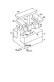
- Memory cell structure example 2 and 3 show examples of the structure of the memory cell.
- FIG. 2 is an example in which a Fin-FET is used as the selection transistor ST
- the example in FIG. 3 is an example in which a Planer-FET is used as the selection transistor ST.
- the semiconductor substrate 21 is, for example, a single crystal silicon substrate.
- the fin-type active area AA1 is disposed on the semiconductor substrate 21.
- the element isolation insulating layer 22 includes an insulating layer (for example, a silicon oxide layer) filled in the trench in the semiconductor substrate 21 and sandwiches the fin-type active area AA1. That is, the element isolation insulating layer 22 has an STI (Shallow Trench Isolation) structure.
- the fin-type active area AA1 has an upper surface in a first direction (a vertical direction perpendicular to the upper surface of the semiconductor substrate 21), and a second direction (a surface parallel to the upper surface of the semiconductor substrate 21) intersecting the first direction. It has a side surface in the inward direction and extends in a third direction (in-plane direction parallel to the upper surface of the semiconductor substrate 21) intersecting the first and second directions.
- the contact portion 24 is connected to the first end of the fin-type active area AA1 in the third direction, and the contact portion 25 is connected to the second end of the fin-type active area AA1 in the third direction.
- the contact portions 24 and 25 and a part of the fin-type active area AA1 include source / drain regions whose resistance is reduced by impurities.
- Contact plugs P1 and P2 are in contact with contact portions 24 and 25, respectively.
- the width of the contact portions 24 and 25 in the second direction is wider than the width of the fin-type active area AA1 in the second direction. This is to prevent the collapse of the fin-type active area AA1 when the memory cell is miniaturized, and to prevent contact failure due to misalignment between the contact plugs P1, P2 and the contact portions 24, 25. There is significance in.
- the selection transistor ST includes a fin-type active area AA1 as a channel, and a gate insulating layer 26 and a gate electrode 27 that cover the upper surface and side surfaces of the fin-type active area AA1.
- the driving force (channel width) of the selection transistor ST is defined by the sum of the width of the upper surface of the fin-type active area AA1 in the second direction and the width of the side surface of the fin-type active area AA1 in the first direction. Is done.
- the Fin-FET of this example is advantageous for miniaturization because it can secure a larger driving force than the Planer-FET.
- the source line (first conductive line) SLj is connected to the contact portion 24 by a contact plug P1.
- the resistance change element MTJ is connected to the contact portion 25 by a contact plug P2.
- the bit line (second conductive line) BLj is connected to the resistance change element MTJ by a contact plug P3.
- Both the source line SLj and the bit line BLj extend in the second direction.
- both the source line SLj and the bit line BLj extend in the second direction intersecting the third direction in which the fin-type active area AA1 extends.
- a conductive layer as an intermediate layer between the source line SLj and the contact portion 24 and between the bit line BLj and the contact portion 25. The size can be reduced.
- the word line (third conductive line) WLi is connected to the gate electrode 27 by a contact plug P4. Word line WLi extends in the third direction.
- the word line WLi extends in the third direction in which the fin-type active area AA1 extends, and the word line WLi is above the source line SLj and the bit line BLj. There is to be. Thereby, for example, the fin type active area AA1 and the word line WLi can be overlapped with each other in the first direction, so that the size of the memory cell can be reduced.
- the active area AA is sandwiched between element isolation insulating layers 22 having an STI structure.
- the active area AA has an upper surface in the first direction, a constant width in the second direction, and extends in the third direction.
- the selection transistor ST includes an active area AA as a channel, and a gate insulating layer 26 and a gate electrode 27 that cover the upper surface of the active area AA.
- the source line (first conductive line) SLj is connected to the first end of the active area AA in the third direction by the contact plug P1.
- the resistance change element MTJ is connected to the second end of the active area AA in the third direction by the contact plug P2.
- Each of the first and second end portions of the active area AA includes source / drain regions whose resistance is reduced by impurities.
- the bit line (second conductive line) BLj is connected to the resistance change element MTJ by a contact plug P3.
- the word line (third conductive line) WLi is connected to the gate electrode 27 by a contact plug P4. Both the source line SLj and the bit line BLj extend in the second direction, and the word line WLi extends in the third direction.
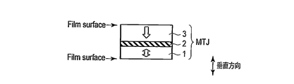
- FIG. 4 shows a basic structure of a magnetoresistive effect element as a resistance change element.
- the magnetoresistive effect element MTJ includes a storage layer (ferromagnetic layer) 1 having a perpendicular and variable magnetization, a tunnel barrier layer (insulating layer) 2 in a direction (vertical direction) perpendicular to the film surface (Film surface), and It has a laminated structure in which reference layers (ferromagnetic layers) 3 having perpendicular and invariant magnetization are arranged in this order.
- variable magnetization means that the magnetization direction does not change before and after writing
- variable magnetization means that the magnetization direction can change in the opposite direction before and after writing
- writing means spin transfer writing that applies spin torque to the magnetization of the memory layer 1 by flowing a spin injection current (spin-polarized electrons) through the magnetoresistive element MTJ.
- the magnetization direction of the storage layer 1 is the same as the magnetization direction of the reference layer 3 (parallel state).
- the resistance value of the magnetoresistive element MTJ changes depending on the relative magnetization directions of the reference layer 3 and the storage layer 1 due to the magnetoresistive effect. That is, the resistance value of the magnetoresistive element MTJ is low in the parallel state and high in the antiparallel state.
- the resistance value in the parallel state is R0
- the resistance value in the anti-parallel state is R1
- the value defined by (R1-R0) / R0 is called the MR (magnetoresistance) ratio.
- the magnetization of the reference layer 3 is fixed while facing the storage layer 1 side, but may be fixed while facing the opposite side to the storage layer 1. Further, when the magnetoresistive element MTJ is disposed on the semiconductor substrate, the vertical relationship between the reference layer 3 and the storage layer 1 is not limited.
- the magnetoresistive element MTJ when the reference layer 3 is above the storage layer 1, the magnetoresistive element MTJ is called a top pin type, and when the reference layer 3 is below the storage layer 1, the magnetoresistive element The MTJ is called a bottom pin type.
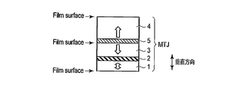
- FIG. 5 shows an example of a magnetoresistive effect element having a shift cancel layer.
- the magnetoresistive effect element MTJ includes a storage layer (ferromagnetic layer) 1 having a perpendicular and variable magnetization, a tunnel barrier layer (insulating layer) 2 and a reference layer having a perpendicular and invariable magnetization (ferromagnetism). Layer) having a laminated structure arranged in the order of 3.
- the magnetoresistive effect element MTJ includes a shift cancel layer (ferromagnetic layer) 4 having perpendicular and invariable magnetization on the reference layer 3 side.
- a nonmagnetic layer (for example, a metal layer) 5 is disposed between the reference layer 3 and the shift cancel layer 4.
- the reference layer 3 and the storage layer 1 have perpendicular magnetization.
- the leakage magnetic field (stray magnetic3field) from the reference layer 3 is oriented in the magnetization direction (vertical direction) of the storage layer 1, so that a leakage magnetic field having a large vertical component is applied to the storage layer 1.
- This leakage magnetic field acts in a direction that makes the magnetization direction of the storage layer 1 the same (parallel state) as the magnetization direction of the reference layer 3.
- the anti-parallel state becomes unstable due to the leakage magnetic field from the reference layer 3.
- the storage layer 1 cannot maintain the antiparallel state. Even when the leakage magnetic field is smaller than the coercive force of the storage layer 1, the magnetization of the storage layer 1 is reversed from the antiparallel state to the parallel state by the leakage magnetic field in consideration of the fluctuation of magnetization due to thermal disturbance. Sometimes.
- the shift cancel layer 4 is provided in order to solve such a problem.
- the reference layer 3 and the shift cancel layer 4 are stacked on each other.
- the magnetization direction of the shift cancel layer 4 is set to be opposite to the magnetization direction of the reference layer 3.
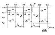
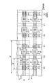
- FIG. 6 shows a memory cell array according to the first embodiment.
- FIG. 7 shows a layout of the memory cell array of FIG.
- the first embodiment relates to a so-called two-transistor-two-element type memory cell array in which one memory cell includes two selection transistors and two resistance change elements. That is, in FIGS. 6 and 7, the area X1 corresponds to a memory cell storing 1 bit.
- the fin-type active area AA1 corresponds to, for example, the fin-type active area AA1 in FIG.
- the fin-type active area AA2 has the same structure as the fin-type active area AA1.
- the fin type active area AA3 connects the two fin type active areas AA1 and AA2.
- the fin-type active areas AA1, AA2, and AA3 are laid out in a straight line and integrally extend in the third direction.
- Fin-type active areas AA1 and AA2 are each covered with a gate electrode 27.
- the width L of the gate electrode 27 in the third direction corresponds to the channel length of the selection transistor ST.
- W is the width of the fin-type active area AA1, AA2 in the second direction.
- the word line WL0 extends in the third direction while overlapping the fin-type active areas AA1, AA2, and AA3.
- the word line WL0 is commonly connected to the gate electrode 27 that covers the fin-type active area AA1 and the gate electrode 27 that covers the fin-type active area AA2.
- the source lines SL0 and SL1 are respectively connected to the first ends of the fin-type active areas AA1 and AA2 in the third direction via contact plugs.
- the bit lines BL0 and BL1 are connected to the second ends of the fin-type active areas AA1 and AA2 in the third direction via the magnetoresistive effect element MTJ, respectively.
- the size of one memory cell is 2F (second direction) ⁇ It is defined by 8F (third direction).
- F is a feature size, for example, and is a minimum processing dimension in each generation of the resistance change memory.
- FIG. 8 shows a memory cell array according to the second embodiment.
- FIG. 9 shows a layout of the memory cell array of FIG.
- the second embodiment also relates to a so-called two-transistor-two-element type memory cell array in which one memory cell includes two selection transistors and two resistance change elements. That is, in FIGS. 8 and 9, the area X2 corresponds to a memory cell storing 1 bit.
- the second embodiment is different from the first embodiment in that one source line SL0 is commonly connected to two select transistors ST in one memory cell.
- the fin-type active area AA1 corresponds to, for example, the fin-type active area AA1 in FIG.
- the fin-type active area AA2 has the same structure as the fin-type active area AA1.
- the fin-type active areas AA1 and AA2 are laid out in a straight line and integrally extend in the third direction.
- Fin-type active areas AA1 and AA2 are each covered with a gate electrode 27.
- the width L of the gate electrode 27 in the third direction corresponds to the channel length of the selection transistor ST.
- W is the width of the fin-type active area AA1, AA2 in the second direction.
- the word line WL0 extends in the third direction while overlapping the fin-type active areas AA1 and AA2.
- the word line WL0 is commonly connected to the gate electrode 27 that covers the fin-type active area AA1 and the gate electrode 27 that covers the fin-type active area AA2.
- the source line SL0 is connected to the first ends of the fin-type active areas AA1, AA2 in the third direction via contact plugs.
- the bit lines BL0 and BL1 are connected to the second ends of the fin-type active areas AA1 and AA2 in the third direction via the magnetoresistive effect element MTJ, respectively.
- the size of one memory cell is 2F (second direction) ⁇ It is defined by 5F (third direction). That is, the second embodiment can reduce the size of one memory cell in the third direction as compared with the first embodiment.
- the number of conductive lines (bit lines BL0 and BL1 and source line SL0) arranged in the third direction is three in one memory cell. This means that 1.5 conductive lines are connected to one transistor ST and one magnetoresistive element MTJ.
- the number of conductive lines (bit lines BL0 and BL1 and source lines SL0 and SL1) arranged in the third direction is four. is there. This means that two conductive lines are connected to one transistor ST and one magnetoresistive element MTJ.
- effect FIG. 10 shows the effect of the MRAM according to the first and second embodiments.
- the miniaturization of the selection transistor can be effectively linked to the miniaturization of the memory cell.
- the cell size of the MRAM according to these embodiments can be made smaller than the cell size of the embedded SRAM (Embedded SRAM) or the embedded DRAM (Embedded DRAM).
- 11 memory cell array
- 12 first driver
- 13A first driver / sinker
- 13B second driver / sinker
- 14 control circuit
- 21 semiconductor substrate
- 22 element isolation insulating layer
- 23 fin Type semiconductor layer (channel)
- 24 first part (source / drain)
- 25 second part (source / drain)
- AA active area
- WLi word line
- BLj bit line
- SLj source line .
Landscapes
- Mram Or Spin Memory Techniques (AREA)
- Hall/Mr Elements (AREA)
- Semiconductor Memories (AREA)
Priority Applications (1)
| Application Number | Priority Date | Filing Date | Title |
|---|---|---|---|
| US15/054,706 US9954029B2 (en) | 2014-09-17 | 2016-02-26 | Resistance change memory |
Applications Claiming Priority (2)
| Application Number | Priority Date | Filing Date | Title |
|---|---|---|---|
| JP2014-188737 | 2014-09-17 | ||
| JP2014188737A JP6121961B2 (ja) | 2014-09-17 | 2014-09-17 | 抵抗変化メモリ |
Related Child Applications (1)
| Application Number | Title | Priority Date | Filing Date |
|---|---|---|---|
| US15/054,706 Continuation US9954029B2 (en) | 2014-09-17 | 2016-02-26 | Resistance change memory |
Publications (1)
| Publication Number | Publication Date |
|---|---|
| WO2016042880A1 true WO2016042880A1 (ja) | 2016-03-24 |
Family
ID=55532925
Family Applications (1)
| Application Number | Title | Priority Date | Filing Date |
|---|---|---|---|
| PCT/JP2015/068824 Ceased WO2016042880A1 (ja) | 2014-09-17 | 2015-06-30 | 抵抗変化メモリ |
Country Status (3)
| Country | Link |
|---|---|
| US (1) | US9954029B2 (https=) |
| JP (1) | JP6121961B2 (https=) |
| WO (1) | WO2016042880A1 (https=) |
Cited By (2)
| Publication number | Priority date | Publication date | Assignee | Title |
|---|---|---|---|---|
| TWI715809B (zh) * | 2016-12-07 | 2021-01-11 | 南韓商三星電子股份有限公司 | 積體電路及其裝置 |
| KR20220039655A (ko) * | 2019-07-24 | 2022-03-29 | 소니 세미컨덕터 솔루션즈 가부시키가이샤 | 불휘발성 메모리 셀, 불휘발성 메모리 셀 어레이 및 불휘발성 메모리 셀 어레이의 정보 기입 방법 |
Families Citing this family (9)
| Publication number | Priority date | Publication date | Assignee | Title |
|---|---|---|---|---|
| US10043971B2 (en) * | 2014-11-18 | 2018-08-07 | Intel Corporation | Non-volatile register file including memory cells having conductive oxide memory element |
| KR20160122912A (ko) * | 2015-04-14 | 2016-10-25 | 에스케이하이닉스 주식회사 | 전자 장치 |
| US9679643B1 (en) | 2016-03-09 | 2017-06-13 | Taiwan Semiconductor Manufacturing Co., Ltd. | Resistive memory device having a trimmable resistance of at least on of a driver and a sinker is trimmed based on a row location |
| US10797223B2 (en) * | 2018-01-29 | 2020-10-06 | Globalfoundries Singapore Pte. Ltd. | Integrated circuits with magnetic random access memory (MRAM) devices and methods for fabricating such devices |
| JP2020155585A (ja) * | 2019-03-20 | 2020-09-24 | キオクシア株式会社 | 不揮発性記憶装置 |
| US10910435B2 (en) * | 2019-03-27 | 2021-02-02 | International Business Machines Corporation | Stackable symmetrical operation memory bit cell structure with bidirectional selectors |
| US11121174B2 (en) * | 2019-11-21 | 2021-09-14 | International Business Machines Corporation | MRAM integration into the MOL for fast 1T1M cells |
| US12073165B2 (en) * | 2021-06-17 | 2024-08-27 | Taiwan Semiconductor Manufacturing Company, Ltd. | Standard cell design |
| KR102929838B1 (ko) * | 2021-10-29 | 2026-02-24 | 에스케이하이닉스 주식회사 | 반도체 메모리를 포함하는 전자 장치 |
Citations (3)
| Publication number | Priority date | Publication date | Assignee | Title |
|---|---|---|---|---|
| JP2005277189A (ja) * | 2004-03-25 | 2005-10-06 | Renesas Technology Corp | 磁気記憶装置 |
| JP2009164319A (ja) * | 2008-01-04 | 2009-07-23 | Renesas Technology Corp | 不揮発性半導体記憶装置 |
| JP2012019105A (ja) * | 2010-07-08 | 2012-01-26 | Toshiba Corp | 抵抗変化メモリ |
Family Cites Families (16)
| Publication number | Priority date | Publication date | Assignee | Title |
|---|---|---|---|---|
| TWI295506B (en) * | 2005-02-03 | 2008-04-01 | Samsung Electronics Co Ltd | Semiconductor device having transistor with vertical gate electrode and method of fabricating the same |
| JP2008130995A (ja) | 2006-11-24 | 2008-06-05 | Toshiba Corp | 半導体記憶装置 |
| JP5518777B2 (ja) | 2011-03-25 | 2014-06-11 | 株式会社東芝 | 半導体記憶装置 |
| JP2013033881A (ja) * | 2011-08-03 | 2013-02-14 | Sony Corp | 記憶素子及び記憶装置 |
| US9419217B2 (en) * | 2011-08-15 | 2016-08-16 | Unity Semiconductor Corporation | Vertical cross-point memory arrays |
| JP2013115272A (ja) | 2011-11-29 | 2013-06-10 | Toshiba Corp | 半導体装置とその製造方法 |
| JP2013162076A (ja) | 2012-02-08 | 2013-08-19 | Toshiba Corp | 半導体装置およびその製造方法 |
| JP2013175570A (ja) * | 2012-02-24 | 2013-09-05 | National Institute Of Advanced Industrial & Technology | 半導体記憶装置およびその製造方法 |
| US9424903B2 (en) * | 2012-05-16 | 2016-08-23 | Sony Corporation | Memory apparatus and memory device |
| KR101929983B1 (ko) * | 2012-07-18 | 2018-12-17 | 삼성전자주식회사 | 저항성 메모리 셀을 갖는 반도체 메모리 장치 및 그 테스트 방법 |
| US9093148B2 (en) * | 2013-03-22 | 2015-07-28 | Kabushiki Kaisha Toshiba | Resistance change type memory |
| KR102335104B1 (ko) * | 2014-05-23 | 2021-12-03 | 삼성전자 주식회사 | 자기 소자 |
| KR102235043B1 (ko) * | 2014-06-09 | 2021-04-05 | 삼성전자주식회사 | 반도체 메모리 장치 |
| KR102222799B1 (ko) * | 2014-07-18 | 2021-03-04 | 삼성전자주식회사 | 자기 저항 메모리 소자 및 그 제조 방법 |
| US9443571B2 (en) * | 2014-09-02 | 2016-09-13 | Kabushiki Kaisha Toshiba | Semiconductor memory, memory system and method of controlling semiconductor memory |
| US20160071566A1 (en) * | 2014-09-04 | 2016-03-10 | Hiromi Noro | Semiconductor device |
-
2014
- 2014-09-17 JP JP2014188737A patent/JP6121961B2/ja active Active
-
2015
- 2015-06-30 WO PCT/JP2015/068824 patent/WO2016042880A1/ja not_active Ceased
-
2016
- 2016-02-26 US US15/054,706 patent/US9954029B2/en active Active
Patent Citations (3)
| Publication number | Priority date | Publication date | Assignee | Title |
|---|---|---|---|---|
| JP2005277189A (ja) * | 2004-03-25 | 2005-10-06 | Renesas Technology Corp | 磁気記憶装置 |
| JP2009164319A (ja) * | 2008-01-04 | 2009-07-23 | Renesas Technology Corp | 不揮発性半導体記憶装置 |
| JP2012019105A (ja) * | 2010-07-08 | 2012-01-26 | Toshiba Corp | 抵抗変化メモリ |
Cited By (5)
| Publication number | Priority date | Publication date | Assignee | Title |
|---|---|---|---|---|
| TWI715809B (zh) * | 2016-12-07 | 2021-01-11 | 南韓商三星電子股份有限公司 | 積體電路及其裝置 |
| KR20220039655A (ko) * | 2019-07-24 | 2022-03-29 | 소니 세미컨덕터 솔루션즈 가부시키가이샤 | 불휘발성 메모리 셀, 불휘발성 메모리 셀 어레이 및 불휘발성 메모리 셀 어레이의 정보 기입 방법 |
| US20220262420A1 (en) * | 2019-07-24 | 2022-08-18 | Sony Semiconductor Solutions Corporation | Nonvolatile memory cell, nonvolatile memory cell array, and information writing method of nonvolatile memory cell array |
| US11996130B2 (en) * | 2019-07-24 | 2024-05-28 | Sony Semiconductor Solutions Corporation | Nonvolatile memory cell, nonvolatile memory cell array, and information writing method of nonvolatile memory cell array |
| KR102845218B1 (ko) | 2019-07-24 | 2025-08-12 | 소니 세미컨덕터 솔루션즈 가부시키가이샤 | 불휘발성 메모리 셀, 불휘발성 메모리 셀 어레이 및 불휘발성 메모리 셀 어레이의 정보 기입 방법 |
Also Published As
| Publication number | Publication date |
|---|---|
| US9954029B2 (en) | 2018-04-24 |
| JP6121961B2 (ja) | 2017-04-26 |
| JP2016063023A (ja) | 2016-04-25 |
| US20160181319A1 (en) | 2016-06-23 |
Similar Documents
| Publication | Publication Date | Title |
|---|---|---|
| JP6121961B2 (ja) | 抵抗変化メモリ | |
| US9385160B2 (en) | Semiconductor storage device | |
| JP5677186B2 (ja) | 半導体記憶装置 | |
| CN102629659B (zh) | 半导体器件 | |
| US9799383B2 (en) | Magnetic memory device | |
| KR20040038420A (ko) | 자기 메모리 및 그 제조 방법 | |
| TWI627772B (zh) | 電阻變化記憶體 | |
| US9305576B2 (en) | Magnetoresistive element | |
| US20100238718A1 (en) | Semiconductor memory device | |
| US20150069555A1 (en) | Magnetic memory | |
| JP2010212661A (ja) | 磁気ランダムアクセスメモリ | |
| US8861251B2 (en) | Semiconductor storage device | |
| US20110180861A1 (en) | Magnetic random access memory having magnetoresistive effect element | |
| US7046546B1 (en) | Semiconductor memory device | |
| JP2014049547A (ja) | 半導体記憶装置 | |
| JP2005191523A (ja) | マグネチックラム | |
| JP5076387B2 (ja) | 磁気記憶装置 | |
| US7649766B2 (en) | Magnetic storage device | |
| JP2008010511A (ja) | 磁気記憶装置 |
Legal Events
| Date | Code | Title | Description |
|---|---|---|---|
| 121 | Ep: the epo has been informed by wipo that ep was designated in this application |
Ref document number: 15841519 Country of ref document: EP Kind code of ref document: A1 |
|
| NENP | Non-entry into the national phase |
Ref country code: DE |
|
| 122 | Ep: pct application non-entry in european phase |
Ref document number: 15841519 Country of ref document: EP Kind code of ref document: A1 |