WO2016024516A1 - エラストマーの熱伝導性改質剤、熱伝導性改質液晶性エラストマー、液晶性高分子およびその前駆体の使用方法、エラストマーの熱伝導性改質方法、ならびに発熱体および被加熱体 - Google Patents
エラストマーの熱伝導性改質剤、熱伝導性改質液晶性エラストマー、液晶性高分子およびその前駆体の使用方法、エラストマーの熱伝導性改質方法、ならびに発熱体および被加熱体 Download PDFInfo
- Publication number
- WO2016024516A1 WO2016024516A1 PCT/JP2015/072323 JP2015072323W WO2016024516A1 WO 2016024516 A1 WO2016024516 A1 WO 2016024516A1 JP 2015072323 W JP2015072323 W JP 2015072323W WO 2016024516 A1 WO2016024516 A1 WO 2016024516A1
- Authority
- WO
- WIPO (PCT)
- Prior art keywords
- elastomer
- liquid crystalline
- pent
- enoxybenzoate
- thermal conductivity
- Prior art date
Links
- SCIKTJAHTKCLHE-UHFFFAOYSA-N C=CCCCOc(cc1)ccc1C(Oc(cc1)ccc1C#N)=O Chemical compound C=CCCCOc(cc1)ccc1C(Oc(cc1)ccc1C#N)=O SCIKTJAHTKCLHE-UHFFFAOYSA-N 0.000 description 1
Images


Classifications
-
- F—MECHANICAL ENGINEERING; LIGHTING; HEATING; WEAPONS; BLASTING
- F28—HEAT EXCHANGE IN GENERAL
- F28F—DETAILS OF HEAT-EXCHANGE AND HEAT-TRANSFER APPARATUS, OF GENERAL APPLICATION
- F28F13/00—Arrangements for modifying heat-transfer, e.g. increasing, decreasing
- F28F13/18—Arrangements for modifying heat-transfer, e.g. increasing, decreasing by applying coatings, e.g. radiation-absorbing, radiation-reflecting; by surface treatment, e.g. polishing
-
- G—PHYSICS
- G03—PHOTOGRAPHY; CINEMATOGRAPHY; ANALOGOUS TECHNIQUES USING WAVES OTHER THAN OPTICAL WAVES; ELECTROGRAPHY; HOLOGRAPHY
- G03G—ELECTROGRAPHY; ELECTROPHOTOGRAPHY; MAGNETOGRAPHY
- G03G15/00—Apparatus for electrographic processes using a charge pattern
- G03G15/20—Apparatus for electrographic processes using a charge pattern for fixing, e.g. by using heat
-
- C—CHEMISTRY; METALLURGY
- C08—ORGANIC MACROMOLECULAR COMPOUNDS; THEIR PREPARATION OR CHEMICAL WORKING-UP; COMPOSITIONS BASED THEREON
- C08G—MACROMOLECULAR COMPOUNDS OBTAINED OTHERWISE THAN BY REACTIONS ONLY INVOLVING UNSATURATED CARBON-TO-CARBON BONDS
- C08G77/00—Macromolecular compounds obtained by reactions forming a linkage containing silicon with or without sulfur, nitrogen, oxygen or carbon in the main chain of the macromolecule
- C08G77/04—Polysiloxanes
- C08G77/38—Polysiloxanes modified by chemical after-treatment
-
- C—CHEMISTRY; METALLURGY
- C08—ORGANIC MACROMOLECULAR COMPOUNDS; THEIR PREPARATION OR CHEMICAL WORKING-UP; COMPOSITIONS BASED THEREON
- C08L—COMPOSITIONS OF MACROMOLECULAR COMPOUNDS
- C08L101/00—Compositions of unspecified macromolecular compounds
-
- C—CHEMISTRY; METALLURGY
- C08—ORGANIC MACROMOLECULAR COMPOUNDS; THEIR PREPARATION OR CHEMICAL WORKING-UP; COMPOSITIONS BASED THEREON
- C08L—COMPOSITIONS OF MACROMOLECULAR COMPOUNDS
- C08L83/00—Compositions of macromolecular compounds obtained by reactions forming in the main chain of the macromolecule a linkage containing silicon with or without sulfur, nitrogen, oxygen or carbon only; Compositions of derivatives of such polymers
- C08L83/04—Polysiloxanes
- C08L83/06—Polysiloxanes containing silicon bound to oxygen-containing groups
-
- C—CHEMISTRY; METALLURGY
- C09—DYES; PAINTS; POLISHES; NATURAL RESINS; ADHESIVES; COMPOSITIONS NOT OTHERWISE PROVIDED FOR; APPLICATIONS OF MATERIALS NOT OTHERWISE PROVIDED FOR
- C09K—MATERIALS FOR MISCELLANEOUS APPLICATIONS, NOT PROVIDED FOR ELSEWHERE
- C09K5/00—Heat-transfer, heat-exchange or heat-storage materials, e.g. refrigerants; Materials for the production of heat or cold by chemical reactions other than by combustion
- C09K5/08—Materials not undergoing a change of physical state when used
- C09K5/14—Solid materials, e.g. powdery or granular
-
- F—MECHANICAL ENGINEERING; LIGHTING; HEATING; WEAPONS; BLASTING
- F28—HEAT EXCHANGE IN GENERAL
- F28F—DETAILS OF HEAT-EXCHANGE AND HEAT-TRANSFER APPARATUS, OF GENERAL APPLICATION
- F28F1/00—Tubular elements; Assemblies of tubular elements
-
- F—MECHANICAL ENGINEERING; LIGHTING; HEATING; WEAPONS; BLASTING
- F28—HEAT EXCHANGE IN GENERAL
- F28F—DETAILS OF HEAT-EXCHANGE AND HEAT-TRANSFER APPARATUS, OF GENERAL APPLICATION
- F28F21/00—Constructions of heat-exchange apparatus characterised by the selection of particular materials
- F28F21/06—Constructions of heat-exchange apparatus characterised by the selection of particular materials of plastics material
- F28F21/062—Constructions of heat-exchange apparatus characterised by the selection of particular materials of plastics material the heat-exchange apparatus employing tubular conduits
-
- G—PHYSICS
- G03—PHOTOGRAPHY; CINEMATOGRAPHY; ANALOGOUS TECHNIQUES USING WAVES OTHER THAN OPTICAL WAVES; ELECTROGRAPHY; HOLOGRAPHY
- G03G—ELECTROGRAPHY; ELECTROPHOTOGRAPHY; MAGNETOGRAPHY
- G03G15/00—Apparatus for electrographic processes using a charge pattern
- G03G15/20—Apparatus for electrographic processes using a charge pattern for fixing, e.g. by using heat
- G03G15/2003—Apparatus for electrographic processes using a charge pattern for fixing, e.g. by using heat using heat
- G03G15/2014—Apparatus for electrographic processes using a charge pattern for fixing, e.g. by using heat using heat using contact heat
- G03G15/2053—Structural details of heat elements, e.g. structure of roller or belt, eddy current, induction heating
- G03G15/2057—Structural details of heat elements, e.g. structure of roller or belt, eddy current, induction heating relating to the chemical composition of the heat element and layers thereof
-
- C—CHEMISTRY; METALLURGY
- C08—ORGANIC MACROMOLECULAR COMPOUNDS; THEIR PREPARATION OR CHEMICAL WORKING-UP; COMPOSITIONS BASED THEREON
- C08G—MACROMOLECULAR COMPOUNDS OBTAINED OTHERWISE THAN BY REACTIONS ONLY INVOLVING UNSATURATED CARBON-TO-CARBON BONDS
- C08G77/00—Macromolecular compounds obtained by reactions forming a linkage containing silicon with or without sulfur, nitrogen, oxygen or carbon in the main chain of the macromolecule
- C08G77/04—Polysiloxanes
- C08G77/12—Polysiloxanes containing silicon bound to hydrogen
-
- C—CHEMISTRY; METALLURGY
- C08—ORGANIC MACROMOLECULAR COMPOUNDS; THEIR PREPARATION OR CHEMICAL WORKING-UP; COMPOSITIONS BASED THEREON
- C08G—MACROMOLECULAR COMPOUNDS OBTAINED OTHERWISE THAN BY REACTIONS ONLY INVOLVING UNSATURATED CARBON-TO-CARBON BONDS
- C08G77/00—Macromolecular compounds obtained by reactions forming a linkage containing silicon with or without sulfur, nitrogen, oxygen or carbon in the main chain of the macromolecule
- C08G77/04—Polysiloxanes
- C08G77/20—Polysiloxanes containing silicon bound to unsaturated aliphatic groups
-
- G—PHYSICS
- G03—PHOTOGRAPHY; CINEMATOGRAPHY; ANALOGOUS TECHNIQUES USING WAVES OTHER THAN OPTICAL WAVES; ELECTROGRAPHY; HOLOGRAPHY
- G03G—ELECTROGRAPHY; ELECTROPHOTOGRAPHY; MAGNETOGRAPHY
- G03G2215/00—Apparatus for electrophotographic processes
- G03G2215/20—Details of the fixing device or porcess
- G03G2215/2003—Structural features of the fixing device
- G03G2215/2016—Heating belt
- G03G2215/2025—Heating belt the fixing nip having a rotating belt support member opposing a pressure member
-
- G—PHYSICS
- G03—PHOTOGRAPHY; CINEMATOGRAPHY; ANALOGOUS TECHNIQUES USING WAVES OTHER THAN OPTICAL WAVES; ELECTROGRAPHY; HOLOGRAPHY
- G03G—ELECTROGRAPHY; ELECTROPHOTOGRAPHY; MAGNETOGRAPHY
- G03G2215/00—Apparatus for electrophotographic processes
- G03G2215/20—Details of the fixing device or porcess
- G03G2215/2003—Structural features of the fixing device
- G03G2215/2016—Heating belt
- G03G2215/2035—Heating belt the fixing nip having a stationary belt support member opposing a pressure member
-
- Y—GENERAL TAGGING OF NEW TECHNOLOGICAL DEVELOPMENTS; GENERAL TAGGING OF CROSS-SECTIONAL TECHNOLOGIES SPANNING OVER SEVERAL SECTIONS OF THE IPC; TECHNICAL SUBJECTS COVERED BY FORMER USPC CROSS-REFERENCE ART COLLECTIONS [XRACs] AND DIGESTS
- Y10—TECHNICAL SUBJECTS COVERED BY FORMER USPC
- Y10T—TECHNICAL SUBJECTS COVERED BY FORMER US CLASSIFICATION
- Y10T428/00—Stock material or miscellaneous articles
- Y10T428/13—Hollow or container type article [e.g., tube, vase, etc.]
- Y10T428/1352—Polymer or resin containing [i.e., natural or synthetic]
- Y10T428/1386—Natural or synthetic rubber or rubber-like compound containing
-
- Y—GENERAL TAGGING OF NEW TECHNOLOGICAL DEVELOPMENTS; GENERAL TAGGING OF CROSS-SECTIONAL TECHNOLOGIES SPANNING OVER SEVERAL SECTIONS OF THE IPC; TECHNICAL SUBJECTS COVERED BY FORMER USPC CROSS-REFERENCE ART COLLECTIONS [XRACs] AND DIGESTS
- Y10—TECHNICAL SUBJECTS COVERED BY FORMER USPC
- Y10T—TECHNICAL SUBJECTS COVERED BY FORMER US CLASSIFICATION
- Y10T428/00—Stock material or miscellaneous articles
- Y10T428/13—Hollow or container type article [e.g., tube, vase, etc.]
- Y10T428/1352—Polymer or resin containing [i.e., natural or synthetic]
- Y10T428/139—Open-ended, self-supporting conduit, cylinder, or tube-type article
- Y10T428/1393—Multilayer [continuous layer]
Definitions
- the present invention relates to a thermal conductivity modifier for elastomer, a thermal conductivity modified liquid crystalline elastomer, a method for using a liquid crystalline polymer and its precursor, and a method for modifying the thermal conductivity of an elastomer.
- the present invention also relates to a heat conductive modifier for an elastomer, a heating element using a heat conductive modified liquid crystalline elastomer, and an object to be heated.
- a method of adding a heat conductive filler to an elastomer is widely known as an example of a method for obtaining a highly heat conductive elastomer molded body.
- a method for forming an elastic layer of an endless belt for fixing color toner see, for example, JP-A-2013-130712.
- the thermal conductivity of the elastomer molded body is improved as the amount of the heat-conductive filler added to the elastomer is increased.
- the amount added is excessive, the elasticity of the elastomer molded body is lost.
- the amount of thermally conductive filler added is inevitably limited. For this reason, it is extremely difficult to improve the thermal conductivity of the elastomer molded body more than before by simply adding a thermally conductive filler to the elastomer.
- the method according to the first aspect of the present invention is a method in which at least one of a liquid crystalline polymer and a precursor thereof is used as a thermal conductivity modifier for an elastomer. That is, the elastomer thermal conductivity modifier according to the first aspect of the present invention contains at least one of a liquid crystalline polymer and a precursor thereof.
- the “elastomer” here is a rubber or a thermoplastic elastomer, and is preferably a silicone rubber.
- the liquid crystalline polymer may be a main chain type, a side chain type, or a composite type, but is preferably a side chain type.
- the liquid crystalline polymer is preferably a polysiloxane polymer having a mesogenic group.
- the main chain of the liquid crystalline polymer is a polysiloxane polymer.
- the “precursor thereof” is, for example, a mixture of a polysiloxane polymer and a mesogenic compound that can react with the polysiloxane polymer.
- the liquid crystalline polymer preferably exhibits a smectic phase or a nematic phase.
- the mesogenic group constituting such a liquid crystalline polymer includes (4-methoxyphenyl) -4-pent-4-enoxybenzoate, (4-cyanophenyl) -4-pent-4-enoxybenzoate, 4-cyano-4 ′-(4-pent-4-enoxy) -1,1′-biphenyl, (4-nitrophenyl) -4-pent-4-enoxybenzoate, 4-biphenyl [4 ′-( 4-pent-4-enoxy)] benzoate and 4′-cyano-4-biphenyl-4-pent-4-enoxybenzoate, and is preferably at least one selected from the group consisting of (4-methoxy Phenyl) -4-pent-4-enoxybenzoate, (4-cyanophenyl) -4-pent-4-enoxybenzoate and 4-cyano-4 ′-(4-pent-4- Phenoxy) more preferably at least one selected from the group consisting of 1,1'-bipheny
- the introduction rate of the mesogenic group is preferably in the range of 20% by mass or more and 70% by mass or less.
- the thermal conductivity modifier is preferably mainly composed of at least one of the liquid crystalline polymer and its precursor, and more preferably comprises only one of the liquid crystalline polymer and its precursor. preferable.
- this resin thermal conductivity modifier may be used by being added to the elastomer or its raw material, or may be used as a raw material for the elastomer.
- the thermal conductivity of the elastomer molded body can be improved more than before. It became clear that we could do it.
- the method and thermal conductivity modifier according to the first aspect of the present invention can improve the thermal conductivity of the elastomer molded body more than before.
- the method according to the second aspect of the present invention is a method for modifying the thermal conductivity of an elastomer by introducing a mesogenic group into the elastomer raw material.
- the detailed supplement of this method is the same as the supplement of the method according to the first aspect.
- the method according to the third aspect of the present invention is a method of modifying the thermal conductivity of an elastomer by adding at least one of a liquid crystalline polymer and its precursor to an elastomer raw material.
- the detailed supplement of this method is the same as the supplement of the method according to the first aspect.
- the liquid crystalline elastomer according to the fourth aspect of the present invention (that is, the elastomer molded product) preferably has a thermal conductivity of 0.21 W / m ⁇ K or more.
- the liquid crystalline elastomer preferably has a JIS-A hardness in the range of 3 ° to 50 °.
- the heating element according to the fifth aspect of the present invention includes a heating part and an elastic part.
- the “heating element” referred to here is, for example, a resistance heating composite tubular material (resistance heating fixing tube or the like), an induction heating composite tubular material (induction heating fixing tube or the like), or the like.
- the elastic part is formed from an elastomer exhibiting liquid crystallinity.
- the elastomer exhibiting liquid crystallinity preferably exhibits a smectic phase or a nematic phase.
- the elastic portion is provided on at least a part of the heat generating portion.
- the elastic part is preferably filled with a heat conductive filler.
- the said heat generating body is a heat_generation
- a heat generating part turns into a heat generating layer and an elastic part turns into an elastic layer.
- the exothermic seamless composite tubular body is an induction exothermic seamless composite tubular body
- the exothermic layer becomes an induction heat generating layer.
- the elastic layer preferably has a JIS-A hardness within a range of 3 degrees to 50 degrees.
- the “elastomer exhibiting liquid crystallinity” in the above-described heating element preferably has the same characteristics as the above-mentioned liquid crystalline polymer and liquid crystalline elastomer.
- the object to be heated according to the fifth aspect of the present invention includes a base portion and an elastic portion.
- the “heated body” mentioned here is, for example, a fixing tube, a cushion sheet of a flexible printed circuit board, a heat conductive composite sheet installed between a heat generating component and a heat radiating component in an electronic device, and used for heat dissipation.
- Thermal conductive composite sheet provided between pressure / heating metal tool and flexible printed circuit board, heat conductive material for heat dissipation of heat-generating electronic / electric parts such as power transistors, MOS transistors, FETs, thyristors, rectifiers, transformers, Such as an electromagnetic wave absorber.
- the elastic part is formed from an elastomer exhibiting liquid crystallinity.
- the elastomer exhibiting liquid crystallinity preferably exhibits a smectic phase or a nematic phase.
- this elastic part is provided on at least one part of a base
- the elastic part is preferably filled with a heat conductive filler.
- the said to-be-heated body is a seamless composite tubular thing
- substrate part turns into a base layer
- an elastic part turns into an elastic layer.
- the elastic layer preferably has a JIS-A hardness within a range of 3 degrees to 50 degrees.
- the “elastomer exhibiting liquid crystallinity” in the above-mentioned heated body preferably has the same characteristics as the above-mentioned liquid crystalline polymer and liquid crystalline elastomer.
- FIG. 3 is a cross-sectional view taken along line AA in FIG. 2.
- 1 is a simplified configuration diagram of an image fixing device incorporating a seamless fixing tubular material according to a first application example of a thermal conductivity modifier for elastomer according to an embodiment of the present invention.
- FIG. 6 is a sectional view taken along line BB in FIG. 5. It is a simplified block diagram of the image fixing device incorporating the resistance heating seamless fixing tubular material according to the second application example of the thermal conductivity modifier for elastomer according to the embodiment of the present invention. It is CC sectional drawing of FIG.
- the method according to an embodiment of the present invention is a method in which at least one of a liquid crystalline polymer and a precursor thereof is used as an elastomer thermal conductivity modifier (hereinafter referred to as “thermal conductivity modifier for elastomer”).
- the thermal conductivity modifier for elastomers according to the embodiment of the present invention is a liquid crystalline polymer itself, a precursor of a liquid crystalline polymer itself, a mixture of a liquid crystalline polymer and its precursor, or a liquid crystalline polymer.
- the thermal conductivity modifier for the elastomer may be used as a raw material for the elastomer.
- the thermal conductivity modifier for elastomer and the method of using the same will be described in detail.
- the “elastomer or its raw material” to which the thermal conductivity modifier for elastomer is added is rubber or a thermoplastic elastomer or their raw material.
- the rubber and the thermoplastic elastomer will be described in detail.
- silicone rubber examples include silicone rubber, isoprene rubber, butadiene rubber, butyl rubber, chloroprene rubber (neoprene rubber), ethylene propylene rubber, chlorinated polyethylene rubber, styrene-butadiene copolymer rubber, and methyl methacrylate-butadiene.
- Rubber chloroprene rubber, acrylonitrile-butadiene copolymer rubber, ⁇ , ⁇ -unsaturated nitrile-acrylic ester-conjugated diene copolymer rubber, ethylene-vinyl acetate copolymer rubber, chlorosulfonated polyethylene rubber, brominated butyl rubber Acrylic rubber, acrylate polymer rubber, fluorine rubber, epichlorohydrin rubber, nitrile rubber, Titan rubber, urethane rubber, polysulfide rubber, hydrogenated diene rubber, rubber-modified epoxy resin, and other structural units Examples thereof include block copolymer and graft copolymer.
- rubbers may be used alone or in combination of two or more (that is, “rubber” is at least one rubber selected from the group consisting of the above-mentioned plural types of rubbers). including). Of the above-mentioned rubbers, silicone rubber is particularly preferable.
- thermoplastic elastomer examples include styrene thermoplastic elastomer, olefin thermoplastic elastomer, ester thermoplastic elastomer, urethane thermoplastic elastomer, polyamide thermoplastic elastomer, and the like. These thermoplastic elastomers may be used alone or in combination of two or more (that is, the “thermoplastic elastomer” is selected from the group consisting of the above-mentioned plural types of thermoplastic elastomers. At least one thermoplastic elastomer).
- styrene thermoplastic elastomer examples include styrene-butadiene-styrene (SBS) copolymer, styrene-isoprene-styrene (SIS) copolymer, styrene-ethylene / propylene-styrene (SEPS) copolymer, styrene- Examples thereof include an ethylene / butylene-styrene (SEBS) copolymer, a styrene-isoprene / butadiene-styrene copolymer, and a styrene-ethylene / butylene-styrene copolymer grafted with a maleic anhydride thermoplastic elastomer.
- SBS styrene-butadiene-styrene
- SIS styrene-isoprene-styrene
- SEPS propylene
- styrenic thermoplastic elastomers may be used alone or in combination of two or more (that is, the “styrenic thermoplastic elastomer” refers to the above-mentioned plural types of styrenic thermoplastics. Including at least one styrenic thermoplastic elastomer selected from the group consisting of elastomers).
- thermoplastic elastomers examples include ethylene-propylene copolymer, ethylene-propylene-diene terpolymer, ethylene-1-butene copolymer, ethylene-butene-diene terpolymer rubber, propylene- Examples thereof include 1-butene copolymer, ethylene-1-hexene copolymer, propylene-1-hexene copolymer, ethylene-1-octene copolymer, and propylene-1-octene copolymer.
- olefinic thermoplastic elastomers may be used alone or in combination of two or more (that is, the “olefinic thermoplastic elastomer” refers to the above-mentioned plural types of olefinic thermoplastics. Including at least one olefinic thermoplastic elastomer selected from the group consisting of elastomers).
- polyester-based thermoplastic elastomers examples include polyether ester copolymers and polyester ester copolymers. These ester-based thermoplastic elastomers may be used alone or in combination of two or more (that is, the “ester-based thermoplastic elastomer” refers to the above-described plurality of types of ester-based thermoplastic elastomers. Including at least one ester-based thermoplastic elastomer selected from the group consisting of elastomers).
- urethane-based thermoplastic elastomers examples include polyester-type polyurethane elastomers, polyether-type polyurethane elastomers, and polycarbonate-type polyurethane elastomers. These urethane-based thermoplastic elastomers may be used alone or in combination of two or more (that is, the “urethane-based thermoplastic elastomer” refers to the above-mentioned plurality of types of urethane-based thermoplastic elastomers. Including at least one urethane-based thermoplastic elastomer selected from the group consisting of elastomers).
- polyamide-based thermoplastic elastomer examples include polyether block amide copolymers, polyether amide copolymers, and polyester amide copolymers. These polyamide-based thermoplastic elastomers may be used alone or in combination of two or more (that is, the “polyamide-based thermoplastic elastomer” refers to the above-mentioned plurality of types of polyamide-based thermoplastic elastomers. Including at least one polyamide-based thermoplastic elastomer selected from the group consisting of elastomers).
- the thermal conductive modifier for elastomer may be a liquid crystalline polymer itself, a precursor of a liquid crystalline polymer itself, or a liquid crystal. It may be a mixture of a functional polymer and its precursor, or a composition containing at least one of a liquid crystalline polymer and its precursor.
- the thermal conductivity modifier for elastomer is a composition containing a liquid crystalline polymer or the like, the composition preferably contains a liquid crystalline polymer or the like as a main component.
- the “main component” as used herein means one having the highest mass ratio in the composition, and the mass ratio is preferably 50% by mass or more, more preferably 60% by mass or more. 70% by mass or more, more preferably 80% by mass or more, and most preferably 90% by mass or more.
- liquid crystalline polymer is literally a polymer exhibiting liquid crystallinity and may be a main chain type, a side chain type, or a composite. Although it may be a type, it is preferably a side chain type.
- the liquid crystalline polymer preferably exhibits a smectic phase or a nematic phase.
- the liquid crystalline polymer preferably has an elastomeric property. Examples of such a liquid crystalline polymer include a polysiloxane polymer having a mesogenic group (hereinafter referred to as “liquid crystalline polysiloxane polymer”).
- liquid crystalline polysiloxane polymer examples include those in which a mesogen group is introduced at the terminal of the polysiloxane polymer (see, for example, JP-A-1-160986) and the side chain of the polysiloxane polymer.
- examples include those into which a mesogenic group has been introduced (for example, see JP-A-2007-45759), but the latter is preferable from the viewpoint of increasing the density of the mesogenic group.
- the latter liquid crystalline polysiloxane polymer (hereinafter referred to as “side-chain liquid crystalline polysiloxane polymer”) will be described in detail below.
- the introduction rate of the mesogen group with respect to a polysiloxane type polymer exists in the range of 20 mass% or more and 70 mass% or less. This is because when the introduction rate of the mesogenic group to the polysiloxane polymer is set within these ranges, the thermal conductivity can be effectively improved without losing the flexibility of the polysiloxane polymer.
- the introduction rate is more preferably in the range of 30% by mass to 70% by mass, further preferably in the range of 40% by mass to 70% by mass, and more preferably in the range of 50% by mass to 70% by mass. It is particularly preferable that the value falls within the range.
- the side chain type liquid crystalline polysiloxane polymer can be obtained, for example, by subjecting polymethylhydrosiloxane (methyl hydrogen polysiloxane) and a vinyl group-containing mesogenic compound to a hydrosilylation reaction.
- the repeating unit of polymethylhydrosiloxane is preferably about 26 to 51, and its weight average molecular weight is preferably about 1700 to 3200.
- Examples of the vinyl group-containing mesogenic compound that can be used in the embodiment of the present invention include compounds represented by the following chemical formulas (1) to (6).
- the compound represented by the chemical formula (1) is (4-methoxyphenyl) -4-pent-4-enoxybenzoate, and the compound represented by the chemical formula (2) is (4-cyanophenyl) -4-pento.
- the compound represented by the chemical formula (3) is 4-cyano-4 ′-(4-pent-4-enoxy) -1,1′-biphenyl, and is represented by the chemical formula (4)
- the compound shown is (4-nitrophenyl) -4-pent-4-enoxybenzoate
- the compound shown by the chemical formula (5) is 4-biphenyl [4 ′-(4-pent-4-enoxy)]
- the compound represented by the chemical formula (6) is benzoate and is 4′-cyano-4-biphenyl-4-pent-4-enoxybenzoate.
- the precursor of the liquid crystalline polymer is, for example, a mixture of a polymer having a reactive functional group and a mesogenic compound capable of reacting with the reactive functional group.
- a mixture include a mixture of polymethylhydrosiloxane and a vinyl group-containing mesogenic compound capable of hydrosilylation reaction with the polymethylhydrosiloxane.
- additives for example, a compatibilizing agent that improves the compatibility with the elastomer to be added, a thermal conductive filler for adjusting thermal conductivity, a cross-linking agent for liquid crystalline polymers, dilution Agents (dilution polymer, etc.), reaction inhibitors, curing aids and the like.
- a compatibilizing agent that improves the compatibility with the elastomer to be added
- a thermal conductive filler for adjusting thermal conductivity
- a cross-linking agent for liquid crystalline polymers for liquid crystalline polymers
- dilution Agents dilution polymer, etc.
- reaction inhibitors curing aids and the like.
- curing aids curing aids and the like.
- the addition amount of these additives can be determined as appropriate based on the final physical properties of the elastomer.
- the side chain liquid crystalline polysiloxane elastomer obtained by crosslinking the above side chain liquid crystalline polysiloxane polymer preferably has a thermal conductivity of 0.21 W / m ⁇ K or more, and is 0.25 W / More preferably, it has a thermal conductivity of m ⁇ K or higher, more preferably 0.30 W / m ⁇ K or higher, and more preferably 0.35 W / m ⁇ K or higher.
- a polysiloxane elastomer having no liquid crystallinity generally has a thermal conductivity of about 0.20 W / m ⁇ K.
- the side chain liquid crystalline polysiloxane elastomer preferably exhibits a smectic phase or a nematic phase like the side chain liquid crystalline polysiloxane polymer.
- the elastomer thermal conductivity modifier according to the embodiment of the present invention can be applied to a member or the like that requires both elasticity and thermal conductivity.
- the specific application examples are shown below for reference.
- the elastomer thermal conductivity modifier according to the embodiment of the present invention is a seamless fixing belt used in an image fixing device of a color image forming apparatus such as a color copying machine or a color laser beam printer. It can be applied as a raw material for forming an elastic layer of a seamless fixing tube (hereinafter collectively referred to as “seamless fixing tubular product”).
- the seamless fixing tubular material will be described in detail.
- the seamless fixing tubular object is a target to be heated by a heater such as a ceramic heater installed in the image fixing apparatus, that is, an object to be heated.
- a seamless fixing tubular object 100 according to this application example is a flexible tubular body, and mainly includes a base layer 111, an elastic layer 112, and a release layer 113, as shown in FIGS. Has been.
- these layers 111, 112, and 113 will be described in detail.
- the description is abbreviate
- the base layer 111 is a seamless tubular layer, and is preferably formed from a heat-resistant insulating material that can withstand the temperature during use of the seamless fixing tubular object 100.
- a heat-resistant insulating material include special stainless steel and heat-resistant resin.
- the heat resistant resin is preferably a resin mainly composed of a polyimide resin, a polyamideimide resin, or the like, and more preferably a polyimide resin itself.
- the base layer 111 preferably has mechanical characteristics that can withstand the operation of the image fixing apparatus.
- the film thickness of the base layer 111 may be 30 ⁇ m or more.
- the elastic layer 112 is formed from “an elastomer containing a thermal conductivity modifier for elastomer” or “the thermal conductivity modifier for elastomer itself”.
- the elastic layer 112 is preferably composed mainly of silicone rubber or fluororubber.
- the elastic layer 112 preferably has a low hardness and is soft. Specifically, for example, the hardness is preferably in the range of 3 degrees to 50 degrees in terms of JIS-A hardness.
- the thickness of the elastic layer 112 is preferably in the range of 100 ⁇ m to 500 ⁇ m.
- the release layer 113 is formed of at least one selected from the group consisting of fluororesin, silicone rubber and fluororubber.
- fluororesin include polytetrafluoroethylene (PTFE), tetrafluoroethylene-perfluoroalkyl vinyl ether copolymer (PFA), and tetrafluoroethylene-hexafluoropropylene copolymer (FEP). It may be used in a mixture or may be used as a mixture.
- the release layer 113 preferably has a thickness in the range of 5 ⁇ m to 30 ⁇ m, and more preferably in the range of 10 ⁇ m to 20 ⁇ m.
- the release layer 113 is preferably bonded to the elastic layer 112 through a primer.
- the primer thickness is preferably in the range of 2 ⁇ m to 5 ⁇ m.
- the image fixing apparatus 400 mainly includes the above-described seamless fixing tubular body 100, belt guide 210, ceramic heater 220, thermistor 230, and pressure roll 300.
- the seamless fixing tubular object 100 is as described above.
- the belt guide 210 is made of a heat-resistant insulating resin such as polyphenylene sulfide, polyamideimide, polyetheretherketone, or liquid crystal polymer.
- the ceramic heater 220 generates resistance by being energized, and heats the seamless fixing tubular object 100.
- the heat generation temperature of the ceramic heater 220 is controlled based on the measured value of the thermistor 230.
- the pressure roll 300 includes a roll body 301 and a shaft 302.
- the shaft 302 extends to both sides along the rotation axis of the roll body 301 and is connected to a drive motor (not shown). As shown in FIG.
- the roll body 301 is pressed against the seamless fixing tubular object 100, and as a result, a nip portion N is formed between the roll body 301 and the seamless fixing tubular object 100. That is, when the drive motor is driven, the roll body 301 rotates about the rotation axis, and the seamless fixing tubular object 100 that is in pressure contact with the pressure roll 300 is driven. Then, as shown in FIG. 4, the copy paper PP on which the unfixed toner image Tn is formed is sequentially fed into the nip portion N, and the unfixed toner image Tn is sequentially heat-fixed on the copy paper PP. (The toner image after fixing is indicated by symbol Th).
- the thermal conductivity modifier for elastomer according to the embodiment of the present invention is a resistance heat generation seamless fixing used in an image fixing device of a color image forming apparatus such as a color copying machine or a color laser beam printer. It can be applied as a raw material for forming an elastic layer of a belt or a resistance heating seamless fixing tube (hereinafter collectively referred to as a “resistance heating seamless fixing tube”).
- a resistance heating seamless fixing tube hereinafter collectively referred to as a “resistance heating seamless fixing tube”.
- resistance heat generation seamless fixing tubular body is a heating element that generates heat when energized.
- the resistance heat generating seamless fixing tubular object 100A according to this application example is a flexible tubular body similar to the seamless fixing tubular object 100 according to the first application example, and as shown in FIG. A main body 120 and a pair of electrodes 130 are included. Hereinafter, these components 120 and 130 will be described in detail. In addition, since the manufacturing method of such resistance exothermic seamless fixing tubular object 100A is already well-known, the description is abbreviate
- the main body 110 is mainly composed of a heat generating resin layer 121, an elastic layer 122, and a release layer 123, as shown in FIGS.
- these layers 121, 122, and 123 will be described in detail.
- the exothermic resin layer 121 is a seamless tubular layer as shown in FIGS. 5 to 7 and mainly withstands the temperature during use of the resistance exothermic seamless fixing tubular body 100. It is preferably formed from a heat resistant insulating material obtained. Examples of such a heat resistant insulating material include a heat resistant resin.
- the heat resistant resin is preferably a resin mainly composed of a polyimide resin, and more preferably a polyimide resin itself.
- the heat-resistant resin is a resin mainly composed of a polyimide resin
- other heat-resistant resins such as polyamide imide and polyether sulfone are added to the heat-resistant resin within the range that does not impair the essence of the present invention. May be.
- the heat resistant resin includes a conductive filler such as a carbon nanomaterial or metal fine particles. The volume fraction of the conductive filler with respect to the heat generating resin layer 121 can be adjusted depending on the target resistance value.
- the heat generating resin layer 121 has an electrically insulating particle such as alumina, boron nitride, aluminum nitride, silicon carbide, titanium oxide, silica, potassium titanate, alumina, silicon nitride, etc. for the purpose of improving thermal conductivity.
- an electrically insulating particle such as alumina, boron nitride, aluminum nitride, silicon carbide, titanium oxide, silica, potassium titanate, alumina, silicon nitride, etc.
- potassium titanate fiber, acicular titanium oxide, aluminum borate whisker, tetrapotted zinc oxide whisker, sepiolite, fiber particles such as glass fiber, viscosity minerals such as montmorillonite and talc May be added.
- the elastic layer 122 is formed of “an elastomer containing a thermal conductivity modifier for elastomer” or “the thermal conductivity modifier for elastomer itself”.
- the elastic layer 122 is preferably composed mainly of silicone rubber or fluorine rubber.
- the elastic layer 122 preferably has a low hardness and is soft. Specifically, for example, the hardness is preferably in the range of 3 degrees to 50 degrees in terms of JIS-A hardness.
- the thickness of the elastic layer 122 is preferably in the range of 100 ⁇ m to 500 ⁇ m.
- the release layer 123 is preferably formed from at least one selected from the group consisting of fluororesin, silicone rubber and fluororubber.
- fluororesin include polytetrafluoroethylene (PTFE), tetrafluoroethylene-perfluoroalkyl vinyl ether copolymer (PFA), and tetrafluoroethylene-hexafluoropropylene copolymer (FEP). It may be used in a mixture or may be used as a mixture.
- the release layer 123 preferably has a thickness in the range of 5 ⁇ m to 30 ⁇ m, and more preferably in the range of 10 ⁇ m to 20 ⁇ m.
- the release layer 123 is preferably bonded to the heat generating resin layer 112 through a primer.
- the primer thickness is preferably in the range of 2 ⁇ m to 5 ⁇ m.
- the electrode 130 is arrange
- the electrode 130 can be formed from, for example, silver paste.
- As the silver paste for example, those disclosed in International Publication No. 08/016148 can be used.
- the power supply member 510 contacts the electrode 130 as shown in FIG. Accordingly, power is supplied to the heat generating resin layer 121 disposed in contact with the electrode 130, and the heat generating resin layer 121 generates resistance heat.
- Examples of the power supply member 510 include a power supply brush, a power supply roll, and a power supply bar.
- the image fixing device 600 mainly includes the above-described resistance heating seamless fixing tubular body 100 ⁇ / b> A, a belt support body 250, a pressure roll 310, and a power supply roll 510.
- the resistance exothermic seamless fixing tubular body 100A is as described above.
- the belt support 250 is made of a heat-resistant insulating resin such as polyphenylene sulfide, polyamideimide, polyetheretherketone, or liquid crystal polymer, and mainly includes a cylindrical portion 251 and a belt guide portion 252. As shown in FIG. 8, the cylindrical portion 251 is rotatably disposed inside the resistance heat generation seamless fixing tubular body 100 ⁇ / b> A.
- the belt guide portion 252 functions as a stopper when the resistance heat generating seamless fixing tubular body 100A meanders in the width direction.
- the pressure roll 310 includes a roll body 311 and a shaft 312.
- the shaft 312 extends on both sides along the rotation axis of the roll body 311 and is connected to a drive motor (not shown). As shown in FIGS. 8 and 9, the roll body 311 is pressed against the resistance heating seamless fixing tubular body 100A, and as a result, a nip portion N is formed between the roll body 311 and the resistance heating seamless fixing tubular body 100A. The That is, when the drive motor is driven, the roll body 311 rotates around the rotation axis, and the resistance heating seamless fixing tubular body 100A pressed against the pressure roll 310 is driven. Then, as shown in FIG.
- the copy paper PP on which the unfixed toner image is formed is sequentially fed into the nip portion N, and the unfixed toner image is sequentially heat-fixed on the copy paper PP (
- the toner image after fixing is displayed with the symbol Th).
- the power supply roll 510 is connected to the AC power source 530 via the lead wire 520 and is in contact with the electrode 130 of the resistance heating seamless fixing tubular body 100A. For this reason, electricity is supplied from the AC power supply 530 via the power supply roll 510 to the resistance heat generation seamless fixing tubular object 100A.
- the resistance heat generating seamless fixing tubular object 100A When the resistance heat generating seamless fixing tubular object 100A is energized, the heat generating resin layer 121 generates resistance heat as described above.
- the thermal conductivity modifier for elastomer according to the embodiment of the present invention is an induction heat generation seamless fixing used in an image fixing device of a color image forming apparatus such as a color copying machine or a color laser beam printer. It can be applied as a raw material for forming an elastic layer of a belt or an induction heat generation seamless fixing tube (hereinafter collectively referred to as “induction heat generation seamless fixing tube”).
- induction heat generation seamless fixing tube hereinafter, the induction heat generation seamless fixing tubular material will be described in detail.
- the induction heat generation seamless fixing tubular body is a heating element that generates heat by electromagnetic induction.
- the induction heat generation seamless fixing tubular body 100 ⁇ / b> B mainly includes a base layer 141, a nonmagnetic conductive metal layer 142, an elastic layer 143, and a release layer 144.
- these layers 141, 142, 143, and 144 will be described in detail.
- the base layer 141 is mainly formed from resin.
- the “resin” mentioned here is preferably a heat-resistant resin that can withstand the temperature during use of the induction heat generation seamless fixing tubular body 100B.
- a heat resistant resin is preferably a resin mainly composed of a polyimide resin, and more preferably a polyimide resin itself.
- the heat resistant resin is a resin having a polyimide resin as a main component, another heat resistant resin such as polyamide imide or polyether sulfone may be added to the heat resistant resin.
- Non-magnetic conductive metal layer The non-magnetic conductive metal layer 142 is mainly formed of a non-magnetic conductive metal such as silver, aluminum, iron, copper, stainless steel, and the base layer on the outer peripheral side of the base layer 141. 141 so as to be in contact with 141.
- the elastic layer 143 is formed from “an elastomer containing a thermal conductivity modifier for elastomer” or “the thermal conductivity modifier for elastomer itself”.
- the elastic layer 143 preferably contains silicone rubber or fluorine rubber as a main component.
- the elastic layer 143 preferably has a low hardness and is soft. Specifically, for example, the hardness is preferably in the range of 3 degrees to 50 degrees in terms of JIS-A hardness.
- the thickness of the elastic layer 143 is preferably in the range of 100 ⁇ m to 500 ⁇ m.
- the release layer 144 is formed of at least one selected from the group consisting of fluororesin, silicone rubber, and fluororubber, and is disposed in contact with the outer periphery of the elastic layer 143.
- fluororesin include polytetrafluoroethylene (PTFE), tetrafluoroethylene-perfluoroalkyl vinyl ether copolymer (PFA), and tetrafluoroethylene-hexafluoropropylene copolymer (FEP). It may be used in a mixture or may be used as a mixture. In such a case, the release layer 144 preferably has a thickness in the range of 5 ⁇ m to 30 ⁇ m, and more preferably in the range of 10 ⁇ m to 20 ⁇ m.
- the release layer 144 is preferably bonded to the elastic layer 143 through a primer.
- the primer thickness is preferably in the range of 2 ⁇ m to 5 ⁇ m.
- the image fixing device 800 mainly includes the above-described induction heat generation seamless fixing tubular body 100B, the upper belt support 260, the lower belt support 270, the pressure roll 320, and the induction heating coil 710. It is composed of
- the induction heat generation seamless fixing tubular body 100B is as described above.
- the upper belt support 260 is formed of a heat-resistant insulating resin such as polyphenylene sulfide, polyamide imide, polyether ether ketone, or liquid crystal polymer, and supports the upper side of the induction heating seamless fixing tubular body 100B as shown in FIG. is doing.
- the lower belt support 270 supports the lower side of the induction heat generation seamless fixing tubular body 100B as shown in FIG.
- the pressure roll 320 includes a roll body 321 and a shaft 322.
- the shaft 322 extends on both sides along the rotation axis of the roll body 321 and is connected to a drive motor (not shown). As shown in FIG.
- the roll main body 321 is pressed against the induction heat generation seamless fixing tubular body 100B, and as a result, a nip portion N is formed between the roll main body 321 and the induction heat generation seamless fixing tubular body 100B. That is, when the drive motor is driven, the roll body 321 rotates about the rotation axis, and the induction heat generation seamless fixing tubular body 100B pressed against the pressure roll 320 is driven. Then, as shown in FIG. 11, the copy paper PP on which the unfixed toner image is formed is sequentially fed into the nip portion N, and the unfixed toner image is sequentially heat-fixed on the copy paper PP ( The toner image after fixing is displayed with the symbol Th). As shown in FIG.
- the induction heating coil 710 is disposed so as to cover the upper half of the induction heating seamless fixing tubular body 100B, and generates a magnetic flux when energized. Then, by the generation of the magnetic flux, the nonmagnetic conductive metal layer 142 of the induction heating seamless fixing tubular body 100B generates induction heat.
- the temperature of the liquid mixture was adjusted to 110 degreeC. Thereafter, the mixed solution was stirred for 24 hours while being kept at 110 ° C. After completion of the stirring, the solvent was distilled off from the mixture using a rotary evaporator to obtain a crude compound. The crude compound was then dissolved in acetone. Subsequently, ethanol, which is a poor solvent for the crude compound, was added to the acetone solution of the crude compound to reprecipitate the crude compound. Furthermore, after performing the reprecipitation operation three times, the precipitate was collected to obtain a liquid crystalline silicone polymer. The introduction rate of mesogenic groups with respect to polymethylhydrosiloxane was about 43%.
- a polyamic acid solution composition: 3,3 ′, 4,4′-biphenyltetracarboxylic dianhydride (hereinafter abbreviated as “BPDA”) / paraphenylene is applied to the surface of the cylindrical mold whose surface has been subjected to mold release treatment.
- BPDA 4,4′-biphenyltetracarboxylic dianhydride
- PPD diamine
- solid content 17.0% by mass
- the coating film was 10 minutes at 100 ° C., 20 minutes at 150 ° C., 30 minutes at 250 ° C. Heating was sequentially performed at 400 ° C. for 15 minutes to obtain a polyimide tubular product A having a thickness of 60 ⁇ m.
- a primer solution was applied to the surface of the polyimide tubular product A, and the coating film was heated at 150 ° C. for 10 minutes. And after apply
- a primer solution was applied to the outer surface of the elastic layer, and the coating film was heated at 150 ° C. for 10 minutes. And after apply
- Example 2 A liquid crystalline silicone elastomer was obtained in the same manner as in Example 1 except that the heating time at 200 ° C. was changed to 0.75 hour (45 minutes) in (Synthesis of liquid crystalline silicone elastomer). The characteristics of the liquid crystalline silicone elastomer were evaluated.
- This liquid crystalline silicone elastomer exhibited a smectic phase.
- the thermal conductivity of the liquid crystalline silicone elastomer was 0.475 W / m ⁇ K. Further, the hardness of the liquid crystalline silicone elastomer was 45.
- a seamless fixing tubular product was obtained in the same manner as in Example 1 except that the above liquid crystalline silicone elastomer was used.
- this seamless fixing tubular article was mounted on a fixing device of a color laser printer and color printing was performed, the toner was in a good fixing state and a good quality image was obtained.
- Example 3 A liquid crystalline silicone elastomer was obtained in the same manner as in Example 1 except that the heating time at 200 ° C. was changed to 1 hour in (Synthesis of liquid crystalline silicone elastomer), and the liquid crystalline silicone elastomer was obtained in the same manner as in Example 1. The characteristics were evaluated.
- This liquid crystalline silicone elastomer exhibited a smectic phase.
- the thermal conductivity of the liquid crystalline silicone elastomer was 0.290 W / m ⁇ K. Furthermore, the hardness of this liquid crystalline silicone elastomer was 47.
- a seamless fixing tubular product was obtained in the same manner as in Example 1 except that the above liquid crystalline silicone elastomer was used.
- this seamless fixing tubular article was mounted on a fixing device of a color laser printer and color printing was performed, the toner was in a good fixing state and a good quality image was obtained.
- Example 4 A liquid crystalline silicone elastomer was obtained in the same manner as in Example 1 except that the heating time at 200 ° C. was changed to 3 hours in (Synthesis of liquid crystalline silicone elastomer), and the liquid crystalline silicone elastomer was obtained in the same manner as in Example 1. The characteristics were evaluated.
- This liquid crystalline silicone elastomer exhibited a smectic phase.
- the thermal conductivity of the liquid crystalline silicone elastomer was 0.284 W / m ⁇ K. Further, this liquid crystalline silicone elastomer had a hardness of 64.
- a seamless fixing tubular product was obtained in the same manner as in Example 1 except that the above liquid crystalline silicone elastomer was used.
- this seamless fixing tubular article was mounted on a fixing device of a color laser printer and color printing was performed, the toner was in a good fixing state and a good quality image was obtained.
- Example 5 A liquid crystalline silicone elastomer was obtained in the same manner as in Example 1 except that the heating time at 200 ° C. was changed to 5 hours in (Synthesis of liquid crystalline silicone elastomer), and the liquid crystalline silicone elastomer was obtained in the same manner as in Example 1. The characteristics were evaluated.
- This liquid crystalline silicone elastomer exhibited a smectic phase.
- the thermal conductivity of the liquid crystalline silicone elastomer was 0.212 W / m ⁇ K.
- the hardness of this liquid crystalline silicone elastomer was 71.
- a seamless fixing tubular product was obtained in the same manner as in Example 1 except that the above liquid crystalline silicone elastomer was used.
- this seamless fixing tubular article was mounted on a fixing device of a color laser printer and color printing was performed, the toner was in a good fixing state and a good quality image was obtained.
- Example 6 In (Synthesis of liquid crystalline silicone elastomer), the addition amount of the reaction inhibitor was changed to 400 ⁇ L, and the heating time at 200 ° C. was changed to 1 hour to obtain a liquid crystalline silicone elastomer in the same manner as in Example 1. The properties of the liquid crystalline silicone elastomer were evaluated in the same manner as in Example 1.
- This liquid crystalline silicone elastomer exhibited a smectic phase.
- the thermal conductivity of the liquid crystalline silicone elastomer was 0.275 W / m ⁇ K. Further, this liquid crystalline silicone elastomer had a hardness of 58.
- a seamless fixing tubular product was obtained in the same manner as in Example 1 except that the above liquid crystalline silicone elastomer was used.
- this seamless fixing tubular article was mounted on a fixing device of a color laser printer and color printing was performed, the toner was in a good fixing state and a good quality image was obtained.
- Example 7 In (Synthesis of liquid crystalline silicone elastomer), the addition amount of the reaction inhibitor was changed to 200 ⁇ L, and the heating time at 200 ° C. was changed to 1 hour to obtain a liquid crystalline silicone elastomer in the same manner as in Example 1. The properties of the liquid crystalline silicone elastomer were evaluated in the same manner as in Example 1.
- This liquid crystalline silicone elastomer exhibited a smectic phase.
- the thermal conductivity of this liquid crystalline silicone elastomer was 0.345 W / m ⁇ K. Further, the hardness of the liquid crystalline silicone elastomer was 48.
- a seamless fixing tubular product was obtained in the same manner as in Example 1 except that the above liquid crystalline silicone elastomer was used.
- this seamless fixing tubular article was mounted on a fixing device of a color laser printer and color printing was performed, the toner was in a good fixing state and a good quality image was obtained.
- Example 8 In (Synthesis of liquid crystalline silicone elastomer), the amount of platinum catalyst Pt (dvs) was changed to 0.5 g, and the heating time at 200 ° C. was changed to 1 hour. An elastomer was obtained, and the characteristics of the liquid crystalline silicone elastomer were evaluated in the same manner as in Example 1.
- This liquid crystalline silicone elastomer exhibited a smectic phase.
- the thermal conductivity of the liquid crystalline silicone elastomer was 0.234 W / m ⁇ K. Furthermore, the hardness of this liquid crystalline silicone elastomer was 82.
- a seamless fixing tubular product was obtained in the same manner as in Example 1 except that the above liquid crystalline silicone elastomer was used.
- this seamless fixing tubular article was mounted on a fixing device of a color laser printer and color printing was performed, the toner was in a good fixing state and a good quality image was obtained.
- Example 9 In the same manner as in Example 1, except that the amount of platinum catalyst Pt (dvs) added was changed to 0.01 g and the heating time at 200 ° C. was changed to 1 hour in (Synthesis of liquid crystalline silicone elastomer). An elastomer was obtained, and the characteristics of the liquid crystalline silicone elastomer were evaluated in the same manner as in Example 1.
- This liquid crystalline silicone elastomer exhibited a smectic phase. Further, this liquid crystalline silicone elastomer had a thermal conductivity of 0.854 W / m ⁇ K. Further, the hardness of the liquid crystalline silicone elastomer was 15.
- a seamless fixing tubular product was obtained in the same manner as in Example 1 except that the above liquid crystalline silicone elastomer was used.
- this seamless fixing tubular article was mounted on a fixing device of a color laser printer and color printing was performed, the toner was in a good fixing state and a good quality image was obtained.
- Example 10 In (Synthesis of Liquid Crystalline Silicone Polymer), the amount of 4-cyano-4 ′-(4-pent-4-enoxy) -1,1′-biphenyl was changed to 12.9 g (49.0 mmol), and polymethylhydro Except that the amount of siloxane added was changed to 5 g to obtain a liquid crystalline silicone polymer (mesogenic group introduction rate of about 50%), and the heating time at 200 ° C. was changed to 1 hour in (Synthesis of liquid crystalline silicone elastomer). A liquid crystalline silicone elastomer was obtained in the same manner as in Example 1, and the characteristics of the liquid crystalline silicone elastomer were evaluated in the same manner as in Example 1.
- This liquid crystalline silicone elastomer exhibited a smectic phase. Further, the thermal conductivity of the liquid crystalline silicone elastomer was 0.351 W / m ⁇ K. Further, the hardness of the liquid crystalline silicone elastomer was 70.
- a seamless fixing tubular product was obtained in the same manner as in Example 1 except that the above liquid crystalline silicone elastomer was used.
- this seamless fixing tubular article was mounted on a fixing device of a color laser printer and color printing was performed, the toner was in a good fixing state and a good quality image was obtained.
- Example 11 In (Synthesis of Liquid Crystalline Silicone Polymer), the amount of 4-cyano-4 ′-(4-pent-4-enoxy) -1,1′-biphenyl was changed to 7.75 g (29.4 mmol), and polymethylhydro Except that the amount of siloxane added was changed to 5 g to obtain a liquid crystalline silicone polymer (mesogenic group introduction rate of about 37%), and the heating time at 200 ° C. was changed to 1 hour in (Synthesis of liquid crystalline silicone elastomer). A liquid crystalline silicone elastomer was obtained in the same manner as in Example 1, and the characteristics of the liquid crystalline silicone elastomer were evaluated in the same manner as in Example 1.
- This liquid crystalline silicone elastomer exhibited a smectic phase. Further, this liquid crystalline silicone elastomer had a thermal conductivity of 0.289 W / m ⁇ K. Further, this liquid crystalline silicone elastomer had a hardness of 60.
- a seamless fixing tubular product was obtained in the same manner as in Example 1 except that the above liquid crystalline silicone elastomer was used.
- this seamless fixing tubular article was mounted on a fixing device of a color laser printer and color printing was performed, the toner was in a good fixing state and a good quality image was obtained.
- Example 12 In (Synthesis of Liquid Crystalline Silicone Polymer), the amount of 4-cyano-4 ′-(4-pent-4-enoxy) -1,1′-biphenyl was changed to 12.9 g (49.0 mmol), and polymethylhydro The amount of siloxane added was changed to 5 g to obtain a liquid crystalline silicone polymer (mesogen group introduction rate of about 50%), and the amount of platinum catalyst Pt (dvs) added in 0.01 g of (liquid crystalline silicone elastomer synthesis) was changed to 0.01 g, A liquid crystalline silicone elastomer was obtained in the same manner as in Example 1 except that 0.086 g of 1-dodecene was further added as a curing aid and the heating time at 200 ° C. was changed to 3 hours. The properties of the liquid crystalline silicone elastomer were evaluated.
- This liquid crystalline silicone elastomer exhibited a smectic phase. Further, the thermal conductivity of the liquid crystalline silicone elastomer was 1.07 W / m ⁇ K.
- a seamless fixing tubular product was obtained in the same manner as in Example 1 except that the above liquid crystalline silicone elastomer was used.
- this seamless fixing tubular article was mounted on a fixing device of a color laser printer and color printing was performed, the toner was in a good fixing state and a good quality image was obtained.
- Example 13 A liquid crystalline silicone elastomer was obtained in the same manner as in Example 12 except that the heating time at 200 ° C. was changed to 5 hours, and the characteristics of the liquid crystalline silicone elastomer were evaluated in the same manner as in Example 1.
- This liquid crystalline silicone elastomer exhibited a smectic phase. Further, the thermal conductivity of the liquid crystalline silicone elastomer was 0.505 W / m ⁇ K.
- a seamless fixing tubular product was obtained in the same manner as in Example 1 except that the above liquid crystalline silicone elastomer was used.
- this seamless fixing tubular article was mounted on a fixing device of a color laser printer and color printing was performed, the toner was in a good fixing state and a good quality image was obtained.
- This liquid crystalline silicone elastomer exhibited a smectic phase. Further, the thermal conductivity of the liquid crystalline silicone elastomer was 0.366 W / m ⁇ K.
- a seamless fixing tubular product was obtained in the same manner as in Example 1 except that the above liquid crystalline silicone elastomer was used.
- this seamless fixing tubular article was mounted on a fixing device of a color laser printer and color printing was performed, the toner was in a good fixing state and a good quality image was obtained.
- Example 15 A liquid crystalline silicone elastomer was obtained in the same manner as in Example 14 except that the amount of methylbutinol added was changed to 30 ⁇ L, and the characteristics of the liquid crystalline silicone elastomer were evaluated in the same manner as in Example 1.
- This liquid crystalline silicone elastomer exhibited a smectic phase.
- the thermal conductivity of this liquid crystalline silicone elastomer was 0.455 W / m ⁇ K.
- a seamless fixing tubular product was obtained in the same manner as in Example 1 except that the above liquid crystalline silicone elastomer was used.
- this seamless fixing tubular article was mounted on a fixing device of a color laser printer and color printing was performed, the toner was in a good fixing state and a good quality image was obtained.
- Example 16 A liquid crystalline silicone elastomer was obtained in the same manner as in Example 12 except that the reaction inhibitor of the chemical formula (C) was replaced with methylbutynol of the following chemical formula (E) in (Synthesis of liquid crystalline silicone elastomer). In the same manner, the characteristics of the liquid crystalline silicone elastomer were evaluated.
- This liquid crystalline silicone elastomer exhibited a smectic phase.
- the thermal conductivity of this liquid crystalline silicone elastomer was 0.449 W / m ⁇ K.
- a seamless fixing tubular product was obtained in the same manner as in Example 1 except that the above liquid crystalline silicone elastomer was used.
- this seamless fixing tubular article was mounted on a fixing device of a color laser printer and color printing was performed, the toner was in a good fixing state and a good quality image was obtained.
- Example 17 In (Synthesis of Liquid Crystalline Silicone Polymer), the amount of 4-cyano-4 ′-(4-pent-4-enoxy) -1,1′-biphenyl was changed to 7.7 g (29.3 mmol), and polymethylhydro The amount of siloxane added was changed to 5.0 g to obtain a liquid crystalline silicone polymer (mesogenic group introduction rate of about 30%), and the heating time at 200 ° C. was changed to 5 hours in (Synthesis of liquid crystalline silicone elastomer). The liquid crystalline silicone elastomer was obtained in the same manner as in Example 1, and the characteristics of the liquid crystalline silicone elastomer were evaluated in the same manner as in Example 1.
- This liquid crystalline silicone elastomer exhibited a smectic phase.
- the thermal conductivity of the liquid crystalline silicone elastomer was 0.443 W / m ⁇ K.
- a seamless fixing tubular product was obtained in the same manner as in Example 1 except that the above liquid crystalline silicone elastomer was used.
- this seamless fixing tubular article was mounted on a fixing device of a color laser printer and color printing was performed, the toner was in a good fixing state and a good quality image was obtained.
- Example 18 In (Synthesis of Liquid Crystalline Silicone Polymer), the amount of 4-cyano-4 ′-(4-pent-4-enoxy) -1,1′-biphenyl was changed to 10.2 g (38.8 mmol), and polymethylhydro The amount of siloxane added was changed to 5.0 g to obtain a liquid crystalline silicone polymer (mesogenic group introduction rate of about 40%), except that the heating time at 200 ° C. was changed to 5 hours in (Synthesis of liquid crystalline silicone elastomer). The liquid crystalline silicone elastomer was obtained in the same manner as in Example 1, and the characteristics of the liquid crystalline silicone elastomer were evaluated in the same manner as in Example 1.
- This liquid crystalline silicone elastomer exhibited a smectic phase.
- the thermal conductivity of the liquid crystalline silicone elastomer was 0.447 W / m ⁇ K.
- a seamless fixing tubular product was obtained in the same manner as in Example 1 except that the above liquid crystalline silicone elastomer was used.
- this seamless fixing tubular article was mounted on a fixing device of a color laser printer and color printing was performed, the toner was in a good fixing state and a good quality image was obtained.
- Example 19 In (Synthesis of Liquid Crystalline Silicone Polymer), the amount of 4-cyano-4 ′-(4-pent-4-enoxy) -1,1′-biphenyl was changed to 62.3 g (2.35 mmol), and polymethylhydro The amount of siloxane added was changed to 24.1 g to obtain a liquid crystalline silicone polymer (mesogenic group introduction rate of about 60%), except that the heating time at 200 ° C. was changed to 5 hours in (Synthesis of liquid crystalline silicone elastomer). The liquid crystalline silicone elastomer was obtained in the same manner as in Example 1, and the characteristics of the liquid crystalline silicone elastomer were evaluated in the same manner as in Example 1.
- This liquid crystalline silicone elastomer exhibited a smectic phase. Further, the thermal conductivity of the liquid crystalline silicone elastomer was 0.467 W / m ⁇ K.
- a seamless fixing tubular product was obtained in the same manner as in Example 1 except that the above liquid crystalline silicone elastomer was used.
- this seamless fixing tubular article was mounted on a fixing device of a color laser printer and color printing was performed, the toner was in a good fixing state and a good quality image was obtained.
- This liquid crystalline silicone elastomer exhibited a smectic phase.
- the thermal conductivity of the liquid crystalline silicone elastomer was 0.315 W / m ⁇ K.
- a seamless fixing tubular product was obtained in the same manner as in Example 1 except that the above liquid crystalline silicone elastomer was used.
- this seamless fixing tubular article was mounted on a fixing device of a color laser printer and color printing was performed, the toner was in a good fixing state and a good quality image was obtained.
- Example 21 In (Synthesis of Liquid Crystalline Silicone Polymer), the addition amount of (4-cyanophenyl) -4-pent-4-enoxybenzoate was changed to 1.04 g (3.39 mmol), and the liquid crystalline silicone polymer (mesogen group introduction rate) A liquid crystalline silicone elastomer was obtained in the same manner as in Example 20 except that about 30%) was obtained, and the characteristics of the liquid crystalline silicone elastomer were evaluated in the same manner as in Example 1.
- This liquid crystalline silicone elastomer exhibited a smectic phase.
- the liquid silicone elastomer had a thermal conductivity of 0.378 W / m ⁇ K.
- a seamless fixing tubular product was obtained in the same manner as in Example 1 except that the above liquid crystalline silicone elastomer was used.
- this seamless fixing tubular article was mounted on a fixing device of a color laser printer and color printing was performed, the toner was in a good fixing state and a good quality image was obtained.
- Example 22 In (Synthesis of Liquid Crystalline Silicone Polymer), the amount of (4-cyanophenyl) -4-pent-4-enoxybenzoate added was changed to 1.38 g (4.50 mmol), and the liquid crystalline silicone polymer (mesogen group introduction rate) A liquid crystalline silicone elastomer was obtained in the same manner as in Example 20 except that about 40%) was obtained, and the characteristics of the liquid crystalline silicone elastomer were evaluated in the same manner as in Example 1.
- This liquid crystalline silicone elastomer exhibited a smectic phase.
- the liquid silicone elastomer had a thermal conductivity of 1.134 W / m ⁇ K.
- a seamless fixing tubular product was obtained in the same manner as in Example 1 except that the above liquid crystalline silicone elastomer was used.
- this seamless fixing tubular article was mounted on a fixing device of a color laser printer and color printing was performed, the toner was in a good fixing state and a good quality image was obtained.
- Example 23 In (Synthesis of Liquid Crystalline Silicone Polymer), the addition amount of (4-cyanophenyl) -4-pent-4-enoxybenzoate was changed to 1.73 g (5.64 mmol), and the liquid crystalline silicone polymer (mesogen group introduction rate) A liquid crystalline silicone elastomer was obtained in the same manner as in Example 20 except that about 50%) was obtained, and the characteristics of the liquid crystalline silicone elastomer were evaluated in the same manner as in Example 1.
- This liquid crystalline silicone elastomer exhibited a smectic phase.
- the thermal conductivity of this liquid crystalline silicone elastomer was 0.989 W / m ⁇ K.
- a seamless fixing tubular product was obtained in the same manner as in Example 1 except that the above liquid crystalline silicone elastomer was used.
- this seamless fixing tubular article was mounted on a fixing device of a color laser printer and color printing was performed, the toner was in a good fixing state and a good quality image was obtained.
- This liquid crystalline silicone elastomer exhibited a nematic phase (however, the liquid crystalline silicone polymer exhibited a smectic phase).
- the thermal conductivity of the liquid crystalline silicone elastomer was 0.517 W / m ⁇ K.
- a seamless fixing tubular product was obtained in the same manner as in Example 1 except that the above liquid crystalline silicone elastomer was used.
- this seamless fixing tubular article was mounted on a fixing device of a color laser printer and color printing was performed, the toner was in a good fixing state and a good quality image was obtained.
- PMHS indicates a polymethylhydrosiloxane of chemical formula (A) (polymerization degree: 26 to 51, weight average molecular weight (Mw): 1700 to 3200), and “MSGN” is a vinyl group-containing mesogenic compound.
- Pt / C represents a platinum catalyst
- LCDT represents a liquid crystalline silicone polymer
- CR represents a crosslinking agent of formula (B)
- CT represents a platinum catalyst of formula (D)
- DDC represents 1-dodecene
- RI represents a reaction inhibitor
- DMHO represents 3,5-dimethyl-1-hexyn-3-ol of the formula (C)
- MB represents methylbutynol of formula (E)
- t @ 200 ° C represents the heating time at 200 ° C
- Sm represents the smectic phase
- N represents the nematic phase.
- Example 25 (Synthesis of liquid crystalline silicone polymer) 62.3 g (2.35 mmol) of 4-cyano-4 ′-(4-pent-4-enoxy) -1,1′-biphenyl in Example 1 and polymethylhydrosiloxane of formula (A) in Example 1 (Degree of polymerization: 26 to 51, weight average molecular weight (Mw): 1700 to 3200) 24.1 g was dissolved in 200 mL of toluene (hereinafter, this solution is referred to as “solution A”). Further, a catalytic amount of platinum catalyst Pt / C was dispersed in 2-propanol (hereinafter, this dispersion is referred to as “dispersion B”).
- the temperature of the liquid mixture was adjusted to 110 degreeC. Thereafter, the mixed solution was stirred for 24 hours while being kept at 110 ° C. After completion of the stirring, the solvent was distilled off from the mixture using a rotary evaporator to obtain a crude compound. The crude compound was then dissolved in acetone. Subsequently, ethanol, which is a poor solvent for the crude compound, was added to the acetone solution of the crude compound to reprecipitate the crude compound. Furthermore, after performing the reprecipitation operation three times, the precipitate was collected to obtain a liquid crystalline silicone polymer. The introduction rate of mesogenic groups with respect to polymethylhydrosiloxane was about 60%.
- the mixture was further kneaded by passing three times through a three-roll mill. Thereafter, the mixture was heated at 150 ° C. for 0.5 hour (30 minutes), and further heated at 200 ° C. for 5 hours to obtain a filler-containing liquid crystalline silicone elastomer.
- metal silicon content in this liquid crystalline silicone elastomer with a filler was 20% by mass (10% by volume).
- Example 26 A filler-containing liquid crystalline silicone elastomer was prepared in the same manner as in Example 24 except that the amount of metal silicon added was changed to 0.356 g. In addition, metal silicon content in this liquid crystalline silicone elastomer with a filler was 30% by mass (15% by volume). Moreover, when the thermal conductivity of this liquid crystal silicone elastomer with a filler was measured in the same manner as in Example 1, the thermal conductivity was 0.771 W / m ⁇ K.
- a seamless fixing tubular product was obtained in the same manner as in Example 1 except that the above liquid crystalline silicone elastomer was used.
- this seamless fixing tubular article was mounted on a fixing device of a color laser printer and color printing was performed, the toner was in a good fixing state and a good quality image was obtained.
- Example 27 A filler-containing liquid crystalline silicone elastomer was prepared in the same manner as in Example 24 except that the amount of metal silicon added was changed to 0.830 g. In addition, metal silicon content in this liquid crystalline silicone elastomer with a filler was 50% by mass (30% by volume). Further, when the thermal conductivity of the liquid crystalline silicone elastomer with filler was measured in the same manner as in Example 1, the thermal conductivity was 1.421 W / m ⁇ K.
- a seamless fixing tubular product was obtained in the same manner as in Example 1 except that the above liquid crystalline silicone elastomer was used.
- this seamless fixing tubular article was mounted on a fixing device of a color laser printer and color printing was performed, the toner was in a good fixing state and a good quality image was obtained.
- Example 28 A filler-containing liquid crystalline silicone elastomer was prepared in the same manner as in Example 24 except that the amount of metal silicon added was changed to 1.02 g. In addition, metal silicon content in this liquid crystalline silicone elastomer with a filler was 55% by mass (35% by volume). Further, the thermal conductivity of this filler-filled liquid crystalline silicone elastomer was measured in the same manner as in Example 1, and the thermal conductivity was 2.16 W / m ⁇ K. The increase in the thermal conductivity was higher than that in the above example.
- a seamless fixing tubular product was obtained in the same manner as in Example 1 except that the above liquid crystalline silicone elastomer was used.
- this seamless fixing tubular article was mounted on a fixing device of a color laser printer and color printing was performed, the toner was in a good fixing state and a good quality image was obtained.
- Example 29> (Synthesis of liquid crystalline silicone polymer) The addition amount of 4-cyano-4 ′-(4-pent-4-enoxy) -1,1′-biphenyl was changed to 32.6 g (0.124 mmol), and the addition amount of polymethylhydrosiloxane was changed to 10.0 g. A liquid crystalline silicone polymer (mesogenic group introduction rate of about 75%) was obtained in the same manner as in Example 1 except that the substitution was made.
- a cross-linking agent, a reaction inhibitor and a platinum catalyst were mixed into the mixture in the same manner as in Example 1 except that the mixture was replaced with a liquid crystalline silicone polymer.
- the mixture was heated at 80 ° C. for 5 minutes, then heated at 140 ° C. for 30 minutes, further heated at 150 ° C. for 30 minutes, further heated at 170 ° C. for 30 minutes, and finally heated at 200 ° C. for 60 minutes.
- a functional silicone elastomer (white. Silicone rubber (raw rubber, KE-1950-10 (manufactured by Shin-Etsu Chemical Co., Ltd.) processed in the same manner as above was colorless and transparent).
- the temperature increase between each heating pattern was performed at a rate of 5 ° C./min.
- the elastomer thermal conductivity modifier according to the present invention has a feature that the thermal conductivity of an elastomer molded body can be improved more than before, and is used, for example, in an image fixing device of a color image forming apparatus.
- Self-heating seamless tubular material seamless fixing tubular material used in image fixing devices of color image forming apparatuses, other cushion sheets for flexible printed circuit boards, and installed between heat-generating components and heat-dissipating components in electronic devices for heat dissipation
Landscapes
- Chemical & Material Sciences (AREA)
- Engineering & Computer Science (AREA)
- Physics & Mathematics (AREA)
- Chemical Kinetics & Catalysis (AREA)
- Organic Chemistry (AREA)
- Health & Medical Sciences (AREA)
- Medicinal Chemistry (AREA)
- Polymers & Plastics (AREA)
- Thermal Sciences (AREA)
- General Physics & Mathematics (AREA)
- Mechanical Engineering (AREA)
- General Engineering & Computer Science (AREA)
- General Chemical & Material Sciences (AREA)
- Combustion & Propulsion (AREA)
- Materials Engineering (AREA)
- Compositions Of Macromolecular Compounds (AREA)
- Fixing For Electrophotography (AREA)
Abstract
本発明の課題は、エラストマー成形体の熱伝導率を従前よりも向上させることにある。本発明に係る方法は、液晶性高分子およびその前駆体の少なくとも一方をエラストマーの熱伝導性改質剤として使用する方法である。すなわち、本発明に係るエラストマーの熱伝導性改質剤には、液晶性高分子およびその前駆体の少なくとも一方が含有される。なお、熱伝導性改質剤には、液晶性高分子およびその前駆体の少なくとも一方のみが含有されていてもよいし、液晶性高分子およびその前駆体の少なくとも一方とそれ以外の成分が含有されていてもよい。本発明に係る方法および熱伝導性改質剤は、エラストマー成形体の熱伝導率を従前よりも向上させることができる。
Description
本発明は、エラストマーの熱伝導性改質剤、熱伝導性改質液晶性エラストマー、液晶性高分子およびその前駆体の使用方法、エラストマーの熱伝導性改質方法に関する。また、本発明は、エラストマーの熱伝導性改質剤、熱伝導性改質液晶性エラストマーを利用した発熱体および被加熱体に関する。
従前から、高熱伝導性エラストマー成形体を得る手法の一例として、エラストマーに熱伝導性フィラーを添加する方法が広く知られている。具体的には、過去に、カラートナー定着用のエンドレスベルトの弾性層を形成する手法として、そのような方法が採用されている(例えば、特開2013-130712号公報等参照)。
ところで、高熱伝導性エラストマー成形体を調製する際、エラストマーに対する熱伝導性フィラーの添加量を多くすればするほど、エラストマー成形体の熱伝導性が向上する。しかし、その添加量が過多になると、エラストマー成形体の弾性が失われる。したがって、エラストマー成形体に一定レベル以上の弾性を求める場合、必然的に熱伝導性フィラーの添加量が制限されることになる。このため、単純にエラストマーに熱伝導性フィラーを添加する方法だけでは、エラストマー成形体の熱伝導率を従前よりも向上させることは極めて難しい。ところが、このような状況の中、省エネルギー等の観点から、エラストマー成形体の熱伝導率の更なる向上が期待されている。このような現状に鑑み、エラストマー成形体の熱伝導率を従前よりも向上させることを本発明の課題とする。
本発明の第1局面に係る方法は、液晶性高分子およびその前駆体の少なくとも一方をエラストマーの熱伝導性改質剤として使用する方法である。すなわち、本発明の第1局面に係るエラストマーの熱伝導性改質剤には、液晶性高分子およびその前駆体の少なくとも一方が含有される。なお、ここにいう「エラストマー」とは、ゴムまたは熱可塑性エラストマーであって、シリコーンゴムであることが好ましい。また、液晶性高分子は、主鎖型であってもよいし、側鎖型であってもよいし、複合型であってもよいが、側鎖型であることが好ましい。また、液晶性高分子は、メソゲン基を有するポリシロキサン系ポリマーであることが好ましい。液晶性高分子が側鎖型である場合、その液晶性高分子の主鎖がポリシロキサン系ポリマーとなる。なお、かかる場合、「その前駆体」とは、例えば、ポリシロキサン系ポリマーと、そのポリシロキサン系ポリマーと反応可能なメソゲン化合物との混合物である。さらに、この液晶性高分子は、スメクチック相またはネマチック相を示すのが好ましい。このような液晶性高分子を構成するメソゲン基は、(4-メトキシフェニル)-4-ペント-4-エノキシベンゾアート、(4-シアノフェニル)-4-ペント-4-エノキシベンゾアート、4-シアノ-4’-(4-ペント-4-エノキシ)-1,1’-ビフェニル、(4-ニトロフェニル)-4-ペント-4-エノキシベンゾアート、4-ビフェニル[4’-(4-ペント-4-エノキシ)]ベンゾアートおよび4’-シアノ-4-ビフェニル-4-ペント-4-エノキシベンゾアートより成る群から選択される少なくとも一種であることが好ましく、(4-メトキシフェニル)-4-ペント-4-エノキシベンゾアート、(4-シアノフェニル)-4-ペント-4-エノキシベンゾアートおよび4-シアノ-4’-(4-ペント-4-エノキシ)-1,1’-ビフェニルより成る群から選択される少なくとも一種であることがより好ましい。また、メソゲン基の導入率は20質量%以上70質量%以下の範囲内であることが好ましい。そして、熱伝導性改質剤は、液晶性高分子およびその前駆体の少なくとも一方を主成分とすることが好ましく、液晶性高分子およびその前駆体のいずれか一方のみから構成されることがより好ましい。また、この樹脂熱伝導性改質剤は、エラストマーまたはその原材料に添加して使用されてもよいし、エラストマーの原材料として使用されてもよい。
本願発明者らが鋭意検討した結果、液晶性高分子およびその前駆体の少なくとも一方をエラストマーの熱伝導性改質剤として使用すれば、エラストマー成形体の熱伝導率を従前よりも向上させることができることが明らかとなった。このため、本発明の第1局面に係る方法および熱伝導性改質剤は、エラストマー成形体の熱伝導率を従前よりも向上させることができる。
本発明の第2局面に係る方法は、エラストマー原料にメソゲン基を導入して、エラストマーの熱伝導性を改質する方法である。なお、本方法の詳細補足は第1局面に係る方法の詳細補足の通りである。
本発明の第3局面に係る方法は、エラストマー原料に液晶性高分子およびその前駆体の少なくとも一方を添加して、エラストマーの熱伝導性を改質する方法である。なお、本方法の詳細補足は第1局面に係る方法の詳細補足の通りである。
本発明の第4局面に係る液晶性エラストマー(すなわちエラストマー成形体)は、0.21W/m・K以上の熱伝導率を有するのが好ましい。また、この液晶性エラストマーは、3度以上50度以下の範囲内のJIS-A硬度を有するのが好ましい。
本発明の第5局面に係る発熱体は、発熱部および弾性部を備える。なお、ここにいう「発熱体」とは、例えば、抵抗発熱複合管状物(抵抗発熱定着チューブ等)や誘導発熱複合管状物(誘導発熱定着チューブ等)等である。弾性部は、液晶性を示すエラストマーから形成される。液晶性を示すエラストマーは、スメクチック相またはネマチック相を示すのが好ましい。そして、この弾性部は、発熱部の少なくとも一部の上に設けられる。なお、弾性部には、熱伝導性フィラーが充填されるのが好ましい。
本願発明者らが鋭意検討した結果、液晶性を示すエラストマーから形成される弾性部は、液晶性を示さないエラストマーから形成される従前の弾性部よりも熱伝導性が高いことが明らかとなった。このため、この発熱体は、従前の発熱体よりも効率的に熱を外部に発することができる。
なお、上記発熱体が発熱シームレス複合管状物である場合、発熱部は発熱層となり、弾性部は、弾性層となる。また、かかる場合において発熱シームレス複合管状物が誘導発熱シームレス複合管状物である場合、発熱層は誘導発熱層となる。また、かかる場合、弾性層は、3度以上50度以下の範囲内のJIS-A硬度を有するのが好ましい。さらに、上述の発熱体において「液晶性を示すエラストマー」は、上述の液晶性高分子および液晶性エラストマーと同様の特徴を有するのが好ましい。
本発明の第5局面に係る被加熱体は、基体部および弾性部を備える。なお、ここにいう「被加熱体」とは、例えば、定着チューブ、フレキシブルプリント基板のクッションシート、電子機器内の発熱部品と放熱部品の間に設置され放熱に用いられる熱伝導性複合シート、加圧・加熱金属ツールとフレキシブルプリント基板との間に設ける熱伝導性複合シート、パワートランジスタ・MOSトランジスター・FET・サイリスタ・整流器・トランス等の発熱性電子・電気部品の放熱用の熱伝導性材料、電磁波吸収体等である。弾性部は、液晶性を示すエラストマーから形成される。液晶性を示すエラストマーは、スメクチック相またはネマチック相を示すのが好ましい。そして、この弾性部は、基体部の少なくとも一部の上に設けられる。なお、弾性部には、熱伝導性フィラーが充填されるのが好ましい。
本願発明者らが鋭意検討した結果、液晶性を示すエラストマーから形成される弾性部は、液晶性を示さないエラストマーから形成される従前の弾性部よりも熱伝導性が高いことが明らかとなった。このため、この被加熱体は、従前の被加熱体よりも効率的に熱を吸収または通過させることができる。
なお、上記被加熱体がシームレス複合管状物である場合、基体部は基層となり、弾性部は、弾性層となる。また、かかる場合、弾性層は、3度以上50度以下の範囲内のJIS-A硬度を有するのが好ましい。さらに、上述の被加熱体において「液晶性を示すエラストマー」は、上述の液晶性高分子および液晶性エラストマーと同様の特徴を有するのが好ましい。
本発明の実施の形態に係る方法は、液晶性高分子およびその前駆体の少なくとも一方をエラストマーの熱伝導性改質剤(以下「エラストマー用熱伝導性改質剤」という)として使用する方法である。すなわち、本発明の実施の形態に係るエラストマー用熱伝導性改質剤は、液晶性高分子そのもの、液晶性高分子の前駆体そのもの若しくは液晶性高分子とその前駆体の混合物、または液晶性高分子およびその前駆体の少なくとも一方を含有する組成物である。つまり、このエラストマー用熱伝導性改質剤は、エラストマーまたはその原材料に添加されて使用され得る。また、液晶性高分子(前駆体から変換されたものを含む)がエラストマー性を有する場合、エラストマー用熱伝導性改質剤は、エラストマーの原材料として使用されてもよい。以下、このエラストマー用熱伝導性改質剤およびその使用方法について詳述する。
なお、エラストマー用熱伝導性改質剤の添加対象となる「エラストマーまたはその原材料」は、ゴムもしくは熱可塑性エラストマーまたはそれらの原材料である。以下、ゴムおよび熱可塑性エラストマーについて詳述する。
ここにいう「ゴム」としては、例えば、シリコーンゴム、イソプレンゴム、ブタジエンゴム、ブチルゴム、クロロプレンゴム(ネオプレンゴム)、エチレンプロピレンゴム、塩素化ポリエチレンゴム、スチレン-ブタジエン系共重合ゴム、メチルメタクリレート-ブタジエンゴム、クロロプレン系ゴム、アクリロニトリル-ブタジエン系共重合ゴム、α、β-不飽和ニトリル-アクリル酸エステル-共役ジエン共重合ゴム、エチレン-酢酸ビニル共重合体ゴム、クロロスルホン化ポリエチレンゴム、臭素化ブチルゴム、アクリルゴム、アクリル酸エステル重合体ゴム、フッ素ゴム、エピクロルヒドリンゴム、ニトリルゴム、タイタンゴム、ウレタンゴム、多硫化ゴム、水添ジエン系ゴム、ゴム変性型エポキシ樹脂、その他これらの構成単位を有するブロック共重合およびグラフト共重合体等が挙げられる。なお、これらのゴムは、単独で用いられてもよいし、2種類以上組み合わせて用いられてもよい(すなわち、「ゴム」は、上記複数種類のゴムより成る群から選択される少なくとも一種のゴムを含む)。また、上述のゴムの中でも特にシリコーンゴムが好ましい。
また、ここにいう「熱可塑性エラストマー」としては、例えば、スチレン系熱可塑性エラストマー、オレフィン系熱可塑性エラストマー、エステル系熱可塑性エラストマー、ウレタン系熱可塑性エラストマー、ポリアミド系熱可塑性エラストマー等が挙げられる。なお、これらの熱可塑性エラストマーは、単独で用いられてもよいし、2種類以上組み合わせて用いられてもよい(すなわち、「熱可塑性エラストマー」は、上記複数種類の熱可塑性エラストマーより成る群から選択される少なくとも一種の熱可塑性エラストマーを含む)。
スチレン系熱可塑性エラストマーとしては、例えば、スチレン-ブタジエン-スチレン(SBS)共重合体、スチレン-イソプレン-スチレン(SIS)共重合体、スチレン-エチレン/プロピレン-スチレン(SEPS)共重合体、スチレン-エチレン/ブチレン-スチレン(SEBS)共重合体、スチレン-イソプレン/ブタジエン-スチレン共重合体、無水マレイン酸熱可塑性エラストマーでグラフトされたスチレン-エチレン/ブチレン-スチレン共重合体等が挙げられる。なお、これらのスチレン系熱可塑性エラストマーは、単独で用いられてもよいし、2種類以上組み合わせて用いられてもよい(すなわち、「スチレン系熱可塑性エラストマー」は、上記複数種類のスチレン系熱可塑性エラストマーより成る群から選択される少なくとも一種のスチレン系熱可塑性エラストマーを含む)。
オレフィン系熱可塑性エラストマーとしては、例えば、エチレン-プロピレン共重合体、エチレン-プロピレン-ジエン三元共重合体、エチレン-1-ブテン共重合体、エチレン-ブテン-ジエン三元共重合ゴム、プロピレン-1-ブテン共重合体、エチレン-1-ヘキセン共重合体、プロピレン-1-ヘキセン共重合体、エチレン-1-オクテン共重合体、プロピレン-1-オクテン共重合体等が挙げられる。なお、これらのオレフィン系熱可塑性エラストマーは、単独で用いられてもよいし、2種類以上組み合わせて用いられてもよい(すなわち、「オレフィン系熱可塑性エラストマー」は、上記複数種類のオレフィン系熱可塑性エラストマーより成る群から選択される少なくとも一種のオレフィン系熱可塑性エラストマーを含む)。
ポリエステル系熱可塑性エラストマーとしては、例えば、ポリエーテルエステル共重合体、ポリエステルエステル共重合体等が挙げられる。なお、これらのエステル系熱可塑性エラストマーは、単独で用いられてもよいし、2種類以上組み合わせて用いられてもよい(すなわち、「エステル系熱可塑性エラストマー」は、上記複数種類のエステル系熱可塑性エラストマーより成る群から選択される少なくとも一種のエステル系熱可塑性エラストマーを含む)。
ウレタン系熱可塑性エラストマーとしては、例えば、ポリエステル型ポリウレタンエラストマー、ポリエーテル型ポリウレタンエラストマー、ポリカーボネート型ポリウレタンエラストマー等が挙げられる。なお、これらのウレタン系熱可塑性エラストマーは、単独で用いられてもよいし、2種類以上組み合わせて用いられてもよい(すなわち、「ウレタン系熱可塑性エラストマー」は、上記複数種類のウレタン系熱可塑性エラストマーより成る群から選択される少なくとも一種のウレタン系熱可塑性エラストマーを含む)。
ポリアミド系熱可塑性エラストマーとしては、例えば、ポリエーテルブロックアミド共重合体、ポリエーテルアミド共重合体、ポリエステルアミド共重合体等が挙げられる。なお、これらのポリアミド系熱可塑性エラストマーは、単独で用いられてもよいし、2種類以上組み合わせて用いられてもよい(すなわち、「ポリアミド系熱可塑性エラストマー」は、上記複数種類のポリアミド系熱可塑性エラストマーより成る群から選択される少なくとも一種のポリアミド系熱可塑性エラストマーを含む)。
<エラストマー用熱伝導性改質剤の詳細>
本発明の実施の形態に係るエラストマー用熱伝導性改質剤は、上述の通り、液晶性高分子そのものであってもよいし、液晶性高分子の前駆体そのものであってもよいし、液晶性高分子とその前駆体の混合物であってもよいし、液晶性高分子およびその前駆体の少なくとも一方を含有する組成物であってもよい。エラストマー用熱伝導性改質剤が液晶性高分子等を含有する組成物である場合、その組成物は、液晶性高分子等を主成分とすることが好ましい。なお、ここにいう「主成分」とはその組成物中で最も質量割合が高いものを意味し、その質量割合は50質量%以上であることが好ましく、60質量%以上であることがより好ましく、70質量%以上であることがさらに好ましく、80質量%以上であることが特に好ましく、90質量%以上であることが最も好ましい。先ず、本発明の実施の形態において利用可能な液晶性高分子およびその前駆体について詳述し、その後、その液晶性高分子等と共に組成物を構成し得る添加物等について詳述する。
本発明の実施の形態に係るエラストマー用熱伝導性改質剤は、上述の通り、液晶性高分子そのものであってもよいし、液晶性高分子の前駆体そのものであってもよいし、液晶性高分子とその前駆体の混合物であってもよいし、液晶性高分子およびその前駆体の少なくとも一方を含有する組成物であってもよい。エラストマー用熱伝導性改質剤が液晶性高分子等を含有する組成物である場合、その組成物は、液晶性高分子等を主成分とすることが好ましい。なお、ここにいう「主成分」とはその組成物中で最も質量割合が高いものを意味し、その質量割合は50質量%以上であることが好ましく、60質量%以上であることがより好ましく、70質量%以上であることがさらに好ましく、80質量%以上であることが特に好ましく、90質量%以上であることが最も好ましい。先ず、本発明の実施の形態において利用可能な液晶性高分子およびその前駆体について詳述し、その後、その液晶性高分子等と共に組成物を構成し得る添加物等について詳述する。
(1)液晶性高分子およびその前駆体
液晶性高分子は、文字通り、液晶性を示す高分子であって、主鎖型であってもよいし、側鎖型であってもよいし、複合型であってもよいが、側鎖型であることが好ましい。本発明の実施の形態において、この液晶性高分子は、スメクチック相またはネマチック相を示すのが好ましい。また、この液晶性高分子は、エラストマー性を有するのが好ましい。このような液晶性高分子としては、例えば、メソゲン基を有するポリシロキサン系ポリマー(以下「液晶性ポリシロキサン系ポリマー」という)を挙げることができる。
液晶性高分子は、文字通り、液晶性を示す高分子であって、主鎖型であってもよいし、側鎖型であってもよいし、複合型であってもよいが、側鎖型であることが好ましい。本発明の実施の形態において、この液晶性高分子は、スメクチック相またはネマチック相を示すのが好ましい。また、この液晶性高分子は、エラストマー性を有するのが好ましい。このような液晶性高分子としては、例えば、メソゲン基を有するポリシロキサン系ポリマー(以下「液晶性ポリシロキサン系ポリマー」という)を挙げることができる。
このような液晶性ポリシロキサン系ポリマーとしては、例えば、ポリシロキサン系ポリマーの末端にメソゲン基が導入されたもの(例えば、特開平1-160986号公報等参照)およびポリシロキサン系ポリマーの側鎖としてメソゲン基が導入されたもの(例えば、特開2007-45759号公報等参照)が挙げられるが、メソゲン基の密度を高めることができる等の観点から後者のものが好ましい。以下、後者の液晶性ポリシロキサン系ポリマー(以下「側鎖型液晶性ポリシロキサン系ポリマー」という)について詳述する。なお、ポリシロキサン系ポリマーに対するメソゲン基の導入率は20質量%以上70質量%以下の範囲内であることが好ましい。ポリシロキサン系ポリマーに対するメソゲン基の導入率がこれらの範囲内に設定されると、ポリシロキサン系ポリマーの柔軟性を失うことなく、有効にその熱伝導率を向上させることができるからである。なお、同導入率は30質量%以上70質量%以下の範囲内であることがより好ましく、40質量%以上70質量%以下の範囲内であることがさらに好ましく、50質量%以上70質量%以下の範囲内であることが特に好ましい。
側鎖型液晶性ポリシロキサン系ポリマーは、例えば、ポリメチルヒドロシロキサン(メチルハイドロジェンポリシロキサン)と、ビニル基含有メソゲン化合物とをヒドロシリル化反応させることによって得ることできる。なお、ポリメチルヒドロシロキサンの繰り返し単位は26~51程度であり、その重量平均分子量は1700~3200程度であることが好ましい。
本発明の実施の形態で利用可能なビニル基含有メソゲン化合物としては、例えば、以下の化学式(1)~(6)で示される化合物が挙げられる。なお、化学式(1)で示される化合物は(4-メトキシフェニル)-4-ペント-4-エノキシベンゾアートであり、化学式(2)で示される化合物は(4-シアノフェニル)-4-ペント-4-エノキシベンゾアートであり、化学式(3)で示される化合物は4-シアノ-4’-(4-ペント-4-エノキシ)-1,1’-ビフェニルであり、化学式(4)で示される化合物は(4-ニトロフェニル)-4-ペント-4-エノキシベンゾアートであり、化学式(5)で示される化合物は4-ビフェニル[4’-(4-ペント-4-エノキシ)]ベンゾアートであり、化学式(6)で示される化合物は4’-シアノ-4-ビフェニル-4-ペント-4-エノキシベンゾアートである。


液晶性高分子の前駆体とは、例えば、反応性官能基を有する高分子と、その反応性官能基と反応可能なメソゲン化合物との混合物等である。このような混合物としては、例えば、ポリメチルヒドロシロキサンと、そのポリメチルヒドロシロキサンとヒドロシリル化反応可能なビニル基含有メソゲン化合物との混合物等である。
(2)添加物
添加物としては、例えば、添加対象となるエラストマーとの相溶性を良好なものとする相溶化剤、熱伝導率調整用の熱伝導性フィラー、液晶性ポリマーの架橋剤、希釈剤(希釈用ポリマー等)、反応抑制剤、硬化助剤等が挙げられる。なお、これらの添加物の添加量は、最終的なエラストマーの物性等に基づいて適宜決定され得る。
添加物としては、例えば、添加対象となるエラストマーとの相溶性を良好なものとする相溶化剤、熱伝導率調整用の熱伝導性フィラー、液晶性ポリマーの架橋剤、希釈剤(希釈用ポリマー等)、反応抑制剤、硬化助剤等が挙げられる。なお、これらの添加物の添加量は、最終的なエラストマーの物性等に基づいて適宜決定され得る。
<側鎖型液晶性ポリシロキサン系エラストマーの物性>
上述の側鎖型液晶性ポリシロキサン系ポリマーを架橋して得られる側鎖型液晶性ポリシロキサン系エラストマーは、0.21W/m・K以上の熱伝導率を有することが好ましく、0.25W/m・K以上の熱伝導率を有することがより好ましく、0.30W/m・K以上の熱伝導率を有することがさらに好ましく、0.35W/m・K以上の熱伝導率を有することがさらに好ましく、0.40W/m・K以上の熱伝導率を有することがさらに好ましく、0.45W/m・K以上の熱伝導率を有することが特に好ましい。なお、液晶性を有さないポリシロキサン系エラストマーは、一般的に、0.20W/m・K程度の熱伝導率を有する。
上述の側鎖型液晶性ポリシロキサン系ポリマーを架橋して得られる側鎖型液晶性ポリシロキサン系エラストマーは、0.21W/m・K以上の熱伝導率を有することが好ましく、0.25W/m・K以上の熱伝導率を有することがより好ましく、0.30W/m・K以上の熱伝導率を有することがさらに好ましく、0.35W/m・K以上の熱伝導率を有することがさらに好ましく、0.40W/m・K以上の熱伝導率を有することがさらに好ましく、0.45W/m・K以上の熱伝導率を有することが特に好ましい。なお、液晶性を有さないポリシロキサン系エラストマーは、一般的に、0.20W/m・K程度の熱伝導率を有する。
また、この側鎖型液晶性ポリシロキサン系エラストマーは、側鎖型液晶性ポリシロキサン系ポリマーと同様にスメクチック相またはネマチック相を示すのが好ましい。
<エラストマー用熱伝導性改質剤の応用>
本発明の実施の形態に係るエラストマー用熱伝導性改質剤は、弾性および熱伝導性の両方が必要される部材等に応用することができる。以下、参考までにその具体的な応用例を示す。
本発明の実施の形態に係るエラストマー用熱伝導性改質剤は、弾性および熱伝導性の両方が必要される部材等に応用することができる。以下、参考までにその具体的な応用例を示す。
(1)第1応用例
本発明の実施の形態に係るエラストマー用熱伝導性改質剤は、カラー複写機、カラーレーザービームプリンター等のカラー画像形成装置の画像定着装置に用いられるシームレス定着ベルトやシームレス定着チューブ(以下、まとめて「シームレス定着管状物」と称する)の弾性層を形成する原材料として応用することができる。以下、このシームレス定着管状物について詳述する。なお、このシームレス定着管状物は、画像定着装置に設置されるセラミックヒーター等のヒーターによって加熱される対象すなわち被加熱体となる。
本発明の実施の形態に係るエラストマー用熱伝導性改質剤は、カラー複写機、カラーレーザービームプリンター等のカラー画像形成装置の画像定着装置に用いられるシームレス定着ベルトやシームレス定着チューブ(以下、まとめて「シームレス定着管状物」と称する)の弾性層を形成する原材料として応用することができる。以下、このシームレス定着管状物について詳述する。なお、このシームレス定着管状物は、画像定着装置に設置されるセラミックヒーター等のヒーターによって加熱される対象すなわち被加熱体となる。
<シームレス定着管状物の構成>
本応用例に係るシームレス定着管状物100は、可撓性を有する管状体であって、図1~図3に示されるように、主に、基層111、弾性層112および離型層113から構成されている。以下、これらの層111,112,113について詳述する。なお、このようなシームレス定着管状物100の製造方法は既に公知であるため、その説明を省略する。
本応用例に係るシームレス定着管状物100は、可撓性を有する管状体であって、図1~図3に示されるように、主に、基層111、弾性層112および離型層113から構成されている。以下、これらの層111,112,113について詳述する。なお、このようなシームレス定着管状物100の製造方法は既に公知であるため、その説明を省略する。
(1)基層
基層111は、シームレスの管状層であって、シームレス定着管状物100の使用時温度に耐え得る耐熱絶縁材料から形成されるのが好ましい。このような耐熱絶縁材料としては、例えば、特殊ステンレス鋼や、耐熱性樹脂等が挙げられる。耐熱性樹脂は、ポリイミド樹脂やポリアミドイミド樹脂等を主成分とする樹脂であることが好ましく、ポリイミド樹脂そのものであることがより好ましい。そして、この基層111は、画像定着装置の動作に耐え得る機械的特性を有しているのが好ましい。基層111の膜厚は30μm以上であればよい。
基層111は、シームレスの管状層であって、シームレス定着管状物100の使用時温度に耐え得る耐熱絶縁材料から形成されるのが好ましい。このような耐熱絶縁材料としては、例えば、特殊ステンレス鋼や、耐熱性樹脂等が挙げられる。耐熱性樹脂は、ポリイミド樹脂やポリアミドイミド樹脂等を主成分とする樹脂であることが好ましく、ポリイミド樹脂そのものであることがより好ましい。そして、この基層111は、画像定着装置の動作に耐え得る機械的特性を有しているのが好ましい。基層111の膜厚は30μm以上であればよい。
(2)弾性層
弾性層112は、上述の通り、「エラストマー用熱伝導性改質剤を含むエラストマー」または「エラストマー用熱伝導性改質剤そのもの」から形成される。なお、この弾性層112は、シリコーンゴムまたはフッ素ゴムを主成分とするのが好ましい。この弾性層112は、硬度が低く柔らかいものが好ましい。具体的には、例えばJIS-A硬度で3度以上50度以下の範囲内の硬度であることが好ましい。また、この弾性層112の厚さは100μm以上500μm以下の範囲内であることが好ましい。
弾性層112は、上述の通り、「エラストマー用熱伝導性改質剤を含むエラストマー」または「エラストマー用熱伝導性改質剤そのもの」から形成される。なお、この弾性層112は、シリコーンゴムまたはフッ素ゴムを主成分とするのが好ましい。この弾性層112は、硬度が低く柔らかいものが好ましい。具体的には、例えばJIS-A硬度で3度以上50度以下の範囲内の硬度であることが好ましい。また、この弾性層112の厚さは100μm以上500μm以下の範囲内であることが好ましい。
(3)離型層
離型層113は、フッ素樹脂、シリコーンゴム及びフッ素ゴムより成る群から選択される少なくとも1つから形成されるのが好ましい。フッ素樹脂としては、例えば、ポリテトラフルオロエチレン(PTFE)、テトラフルオロエチレン-パーフルオロアルキルビニルエーテル共重合体(PFA)、テトラフルオロエチレン-ヘキサフルオロプロピレン共重合体(FEP)が挙げられ、これらは単体で利用されてもよいし、混合して利用されてもよい。また、かかる場合、離型層113は、5μm以上30μm以下の範囲内の厚みであることが好ましく、10μm以上20μm以下の範囲内の厚みであることがより好ましい。
離型層113は、フッ素樹脂、シリコーンゴム及びフッ素ゴムより成る群から選択される少なくとも1つから形成されるのが好ましい。フッ素樹脂としては、例えば、ポリテトラフルオロエチレン(PTFE)、テトラフルオロエチレン-パーフルオロアルキルビニルエーテル共重合体(PFA)、テトラフルオロエチレン-ヘキサフルオロプロピレン共重合体(FEP)が挙げられ、これらは単体で利用されてもよいし、混合して利用されてもよい。また、かかる場合、離型層113は、5μm以上30μm以下の範囲内の厚みであることが好ましく、10μm以上20μm以下の範囲内の厚みであることがより好ましい。
そして、この離型層113は、プライマーを介して弾性層112に接着されるのが好ましい。かかる場合、プライマーの厚みは2μm以上5μm以下の範囲内であることが好ましい。
<カラー画像形成装置の画像定着装置>
ここでは、本応用例に係るシームレス定着管状物100が組み込まれた画像定着装置の一実施形態を説明する。画像定着装置400は、図4に示されるように、主に、上述のシームレス定着管状物100、ベルトガイド210、セラミックヒーター220、サーミスタ230および加圧ロール300から構成されている。
ここでは、本応用例に係るシームレス定着管状物100が組み込まれた画像定着装置の一実施形態を説明する。画像定着装置400は、図4に示されるように、主に、上述のシームレス定着管状物100、ベルトガイド210、セラミックヒーター220、サーミスタ230および加圧ロール300から構成されている。
シームレス定着管状物100は、上述の通りである。ベルトガイド210は、ポリフェニレンサルファイド、ポリアミドイミド、ポリエーテルエーテルケトン、液晶ポリマー等の耐熱絶縁性樹脂から形成されている。セラミックヒーター220は、通電されることによって抵抗発熱するものであって、シームレス定着管状物100を加熱する。なお、このセラミックヒーター220の発熱温度は、サーミスタ230の計測値に基づいて制御される。加圧ロール300は、ロール本体301およびシャフト302から構成されている。シャフト302は、ロール本体301の回転軸に沿って両側に延びており、駆動モータ(図示せず)に連結されている。図4に示されるように、ロール本体301はシームレス定着管状物100に圧接され、その結果、ロール本体301とシームレス定着管状物100との間にニップ部Nが形成される。すなわち、駆動モータが駆動されると、ロール本体301が回転軸を中心として回転し、加圧ロール300と圧接されたシームレス定着管状物100が従動する。そして、図4に示されるようにそのニップ部Nに対して、未定着トナー像Tnが形成された複写紙PPが順次送り込まれて、未定着トナー像Tnが順次、複写紙PPに熱定着される(定着後のトナー像は符号Thで表示されている)。
(2)第2応用例
本発明の実施の形態に係るエラストマー用熱伝導性改質剤は、カラー複写機、カラーレーザービームプリンター等のカラー画像形成装置の画像定着装置に用いられる抵抗発熱シームレス定着ベルトや抵抗発熱シームレス定着チューブ(以下、まとめて「抵抗発熱シームレス定着管状物」と称する)の弾性層を形成する原材料として応用することができる。以下、この抵抗発熱シームレス定着管状物について詳述する。なお、この抵抗発熱シームレス定着管状物は、通電されることにより自己が発熱する発熱体である。
本発明の実施の形態に係るエラストマー用熱伝導性改質剤は、カラー複写機、カラーレーザービームプリンター等のカラー画像形成装置の画像定着装置に用いられる抵抗発熱シームレス定着ベルトや抵抗発熱シームレス定着チューブ(以下、まとめて「抵抗発熱シームレス定着管状物」と称する)の弾性層を形成する原材料として応用することができる。以下、この抵抗発熱シームレス定着管状物について詳述する。なお、この抵抗発熱シームレス定着管状物は、通電されることにより自己が発熱する発熱体である。
<抵抗発熱シームレス定着管状物の構成>
本応用例に係る抵抗発熱シームレス定着管状物100Aは、第1応用例に係るシームレス定着管状物100と同様に可撓性を有する管状体であって、図5に示されるように、主に、本体120および一対の電極130から構成される。以下、これらの構成要素120,130について詳述する。なお、このような抵抗発熱シームレス定着管状物100Aの製造方法は既に公知であるため、その説明を省略する。
本応用例に係る抵抗発熱シームレス定着管状物100Aは、第1応用例に係るシームレス定着管状物100と同様に可撓性を有する管状体であって、図5に示されるように、主に、本体120および一対の電極130から構成される。以下、これらの構成要素120,130について詳述する。なお、このような抵抗発熱シームレス定着管状物100Aの製造方法は既に公知であるため、その説明を省略する。
(1)本体
本体110は、図4および図5に示されるように、主に、発熱樹脂層121、弾性層122および離型層123から構成されている。以下、これらの層121,122,123について詳述する。
本体110は、図4および図5に示されるように、主に、発熱樹脂層121、弾性層122および離型層123から構成されている。以下、これらの層121,122,123について詳述する。
(1-1)発熱樹脂層
発熱樹脂層121は、図5から図7に示されているように、シームレスの管状層であって、主として、抵抗発熱シームレス定着管状物100の使用時温度に耐え得る耐熱絶縁材料から形成されるのが好ましい。このような耐熱絶縁材料としては、例えば、耐熱性樹脂等が挙げられる。なお、本実施の形態に係る抵抗発熱シームレス定着管状物100において、耐熱性樹脂は、ポリイミド樹脂を主成分とする樹脂であることが好ましく、ポリイミド樹脂そのものであることがより好ましい。なお、耐熱性樹脂がポリイミド樹脂を主成分とする樹脂である場合、耐熱性樹脂には、本発明の本質を損なわない範囲内で、ポリアミドイミドやポリエーテルスルホンなどの他の耐熱性樹脂が添加されてもよい。そして、この発熱樹脂層121において、その耐熱性樹脂中に、カーボンナノ材料や金属微粒子等の導電性充填材が包含されている。なお、この発熱樹脂層121に対する導電性充填材の体積分率は、目標とする抵抗値に依存して調整され得る。
発熱樹脂層121は、図5から図7に示されているように、シームレスの管状層であって、主として、抵抗発熱シームレス定着管状物100の使用時温度に耐え得る耐熱絶縁材料から形成されるのが好ましい。このような耐熱絶縁材料としては、例えば、耐熱性樹脂等が挙げられる。なお、本実施の形態に係る抵抗発熱シームレス定着管状物100において、耐熱性樹脂は、ポリイミド樹脂を主成分とする樹脂であることが好ましく、ポリイミド樹脂そのものであることがより好ましい。なお、耐熱性樹脂がポリイミド樹脂を主成分とする樹脂である場合、耐熱性樹脂には、本発明の本質を損なわない範囲内で、ポリアミドイミドやポリエーテルスルホンなどの他の耐熱性樹脂が添加されてもよい。そして、この発熱樹脂層121において、その耐熱性樹脂中に、カーボンナノ材料や金属微粒子等の導電性充填材が包含されている。なお、この発熱樹脂層121に対する導電性充填材の体積分率は、目標とする抵抗値に依存して調整され得る。
また、この発熱樹脂層121には、熱伝導性等の向上を目的として、アルミナ、窒化硼素、窒化アルミニウム、炭化珪素、酸化チタン、シリカ、チタン酸カリウム、アルミナ、窒化珪素等の電気絶縁性粒子を、機械的特性等の向上を目的としてチタン酸カリウム繊維、針状酸化チタン、ホウ酸アルミニウムウィスカ、テトラポット状酸化亜鉛ウィスカ、セピオライト、ガラス繊維等の繊維状粒子、モンモリロナイト、タルク等の粘度鉱物を加えてもよい。
(1-2)弾性層
弾性層122は、上述の通り、「エラストマー用熱伝導性改質剤を含むエラストマー」または「エラストマー用熱伝導性改質剤そのもの」から形成される。なお、この弾性層122は、シリコーンゴムまたはフッ素ゴムを主成分とするのが好ましい。この弾性層122は、硬度が低く柔らかいものが好ましい。具体的には、例えばJIS-A硬度で3度以上50度以下の範囲内の硬度であることが好ましい。また、この弾性層122の厚さは100μm以上500μm以下の範囲内であることが好ましい。
弾性層122は、上述の通り、「エラストマー用熱伝導性改質剤を含むエラストマー」または「エラストマー用熱伝導性改質剤そのもの」から形成される。なお、この弾性層122は、シリコーンゴムまたはフッ素ゴムを主成分とするのが好ましい。この弾性層122は、硬度が低く柔らかいものが好ましい。具体的には、例えばJIS-A硬度で3度以上50度以下の範囲内の硬度であることが好ましい。また、この弾性層122の厚さは100μm以上500μm以下の範囲内であることが好ましい。
(1-3)離型層
離型層123は、フッ素樹脂、シリコーンゴム及びフッ素ゴムより成る群から選択される少なくとも1つから形成されるのが好ましい。フッ素樹脂としては、例えば、ポリテトラフルオロエチレン(PTFE)、テトラフルオロエチレン-パーフルオロアルキルビニルエーテル共重合体(PFA)、テトラフルオロエチレン-ヘキサフルオロプロピレン共重合体(FEP)が挙げられ、これらは単体で利用されてもよいし、混合して利用されてもよい。また、かかる場合、離型層123は、5μm以上30μm以下の範囲内の厚みであることが好ましく、10μm以上20μm以下の範囲内の厚みであることがより好ましい。
離型層123は、フッ素樹脂、シリコーンゴム及びフッ素ゴムより成る群から選択される少なくとも1つから形成されるのが好ましい。フッ素樹脂としては、例えば、ポリテトラフルオロエチレン(PTFE)、テトラフルオロエチレン-パーフルオロアルキルビニルエーテル共重合体(PFA)、テトラフルオロエチレン-ヘキサフルオロプロピレン共重合体(FEP)が挙げられ、これらは単体で利用されてもよいし、混合して利用されてもよい。また、かかる場合、離型層123は、5μm以上30μm以下の範囲内の厚みであることが好ましく、10μm以上20μm以下の範囲内の厚みであることがより好ましい。
そして、この離型層123は、プライマーを介して発熱樹脂層112に接着されるのが好ましい。かかる場合、プライマーの厚みは2μm以上5μm以下の範囲内であることが好ましい。
(2)電極
電極130は、図5および図7に示されるように、本体120の両端部分において外表面に露出するように配設されている。この電極130は、例えば、銀ペースト等から形成され得る。なお、銀ペーストとしては、例えば、国際公開第08/016148号に開示されているものが利用可能である。そして、抵抗発熱シームレス定着管状物100Aが使用される際、この電極130には、図8に示されるように、給電部材510が接触する。これにより、電極130に接して配設されている発熱樹脂層121に給電が行われ、発熱樹脂層121が抵抗発熱する。なお、給電部材510としては、例えば、給電ブラシ、給電ロール、給電バー等が挙げられる。
電極130は、図5および図7に示されるように、本体120の両端部分において外表面に露出するように配設されている。この電極130は、例えば、銀ペースト等から形成され得る。なお、銀ペーストとしては、例えば、国際公開第08/016148号に開示されているものが利用可能である。そして、抵抗発熱シームレス定着管状物100Aが使用される際、この電極130には、図8に示されるように、給電部材510が接触する。これにより、電極130に接して配設されている発熱樹脂層121に給電が行われ、発熱樹脂層121が抵抗発熱する。なお、給電部材510としては、例えば、給電ブラシ、給電ロール、給電バー等が挙げられる。
<カラー画像形成装置の画像定着装置>
ここでは、本応用例に係る抵抗発熱シームレス定着管状物100Aが組み込まれた画像定着装置の一実施形態を説明する。この画像定着装置600は、図8および図9に示されるように、主に、上述の抵抗発熱シームレス定着管状物100A、ベルト支持体250、加圧ロール310および給電ロール510から構成されている。
ここでは、本応用例に係る抵抗発熱シームレス定着管状物100Aが組み込まれた画像定着装置の一実施形態を説明する。この画像定着装置600は、図8および図9に示されるように、主に、上述の抵抗発熱シームレス定着管状物100A、ベルト支持体250、加圧ロール310および給電ロール510から構成されている。
抵抗発熱シームレス定着管状物100Aは、上述の通りである。ベルト支持体250は、ポリフェニレンサルファイド、ポリアミドイミド、ポリエーテルエーテルケトン、液晶ポリマー等の耐熱絶縁性樹脂から形成されており、主に、円筒部251およびベルトガイド部252から構成されている。円筒部251は、図8に示されるように、抵抗発熱シームレス定着管状物100Aの内側に回転自在に配置されている。ベルトガイド部252は、抵抗発熱シームレス定着管状物100Aが幅方向に蛇行した場合にストッパーとして機能する。加圧ロール310は、ロール本体311およびシャフト312から構成されている。シャフト312は、ロール本体311の回転軸に沿って両側に延びており、駆動モータ(図示せず)に連結されている。図8および図9に示されるように、ロール本体311は抵抗発熱シームレス定着管状物100Aに圧接され、その結果、ロール本体311と抵抗発熱シームレス定着管状物100Aとの間にニップ部Nが形成される。すなわち、駆動モータが駆動されると、ロール本体311が回転軸を中心として回転し、加圧ロール310と圧接された抵抗発熱シームレス定着管状物100Aが従動する。そして、図9に示されるようにそのニップ部Nに対して、未定着トナー像が形成された複写紙PPが順次送り込まれて、未定着トナー像が順次、複写紙PPに熱定着される(定着後のトナー像が符号Thで表示されている)。給電ロール510は、リード線520を介して交流電源530に接続されていると共に、抵抗発熱シームレス定着管状物100Aの電極130と接触している。このため、抵抗発熱シームレス定着管状物100Aには、交流電源530から給電ロール510を介して電気が供給される。抵抗発熱シームレス定着管状物100Aに通電がなされると、上述の通り、発熱樹脂層121が抵抗発熱する。
(3)第3応用例
本発明の実施の形態に係るエラストマー用熱伝導性改質剤は、カラー複写機、カラーレーザービームプリンター等のカラー画像形成装置の画像定着装置に用いられる誘導発熱シームレス定着ベルトや誘導発熱シームレス定着チューブ(以下、まとめて「誘導発熱シームレス定着管状物」と称する)の弾性層を形成する原材料として応用することができる。以下、この誘導発熱シームレス定着管状物について詳述する。なお、この誘導発熱シームレス定着管状物は、電磁誘導により自己が発熱する発熱体である。
本発明の実施の形態に係るエラストマー用熱伝導性改質剤は、カラー複写機、カラーレーザービームプリンター等のカラー画像形成装置の画像定着装置に用いられる誘導発熱シームレス定着ベルトや誘導発熱シームレス定着チューブ(以下、まとめて「誘導発熱シームレス定着管状物」と称する)の弾性層を形成する原材料として応用することができる。以下、この誘導発熱シームレス定着管状物について詳述する。なお、この誘導発熱シームレス定着管状物は、電磁誘導により自己が発熱する発熱体である。
<誘導発熱シームレス定着管状物の構成>
本応用例に係る誘導発熱シームレス定着管状物100Bは、図10に示されるように、主に、基層141、非磁性伝導性金属層142、弾性層143および離型層144から構成されている。以下、これらの層141,142,143,144について詳述する。
本応用例に係る誘導発熱シームレス定着管状物100Bは、図10に示されるように、主に、基層141、非磁性伝導性金属層142、弾性層143および離型層144から構成されている。以下、これらの層141,142,143,144について詳述する。
(1)基層
基層141は、主として樹脂から形成されている。ここにいう「樹脂」は、誘導発熱シームレス定着管状物100Bの使用時温度に耐え得る耐熱性樹脂であることが好ましい。本実施の形態において、そのような耐熱性樹脂は、ポリイミド樹脂を主成分とする樹脂であることが好ましく、ポリイミド樹脂そのものであることがより好ましい。なお、耐熱性樹脂がポリイミド樹脂を主成分とする樹脂である場合、耐熱性樹脂には、ポリアミドイミドやポリエーテルスルホンなどの他の耐熱性樹脂が添加されてもよい。
基層141は、主として樹脂から形成されている。ここにいう「樹脂」は、誘導発熱シームレス定着管状物100Bの使用時温度に耐え得る耐熱性樹脂であることが好ましい。本実施の形態において、そのような耐熱性樹脂は、ポリイミド樹脂を主成分とする樹脂であることが好ましく、ポリイミド樹脂そのものであることがより好ましい。なお、耐熱性樹脂がポリイミド樹脂を主成分とする樹脂である場合、耐熱性樹脂には、ポリアミドイミドやポリエーテルスルホンなどの他の耐熱性樹脂が添加されてもよい。
(2)非磁性伝導性金属層
非磁性伝導性金属層142は、主として、銀、アルミニウム、鉄、銅、ステンレス鋼等の非磁性伝導性金属から形成されており、基層141の外周側において基層141と接するように配設されている。
非磁性伝導性金属層142は、主として、銀、アルミニウム、鉄、銅、ステンレス鋼等の非磁性伝導性金属から形成されており、基層141の外周側において基層141と接するように配設されている。
(3)弾性層
弾性層143は、上述の通り、「エラストマー用熱伝導性改質剤を含むエラストマー」または「エラストマー用熱伝導性改質剤そのもの」から形成される。なお、この弾性層143は、シリコーンゴムまたはフッ素ゴムを主成分とするのが好ましい。この弾性層143は、硬度が低く柔らかいものが好ましい。具体的には、例えばJIS-A硬度で3度以上50度以下の範囲内の硬度であることが好ましい。また、この弾性層143の厚さは100μm以上500μm以下の範囲内であることが好ましい。
弾性層143は、上述の通り、「エラストマー用熱伝導性改質剤を含むエラストマー」または「エラストマー用熱伝導性改質剤そのもの」から形成される。なお、この弾性層143は、シリコーンゴムまたはフッ素ゴムを主成分とするのが好ましい。この弾性層143は、硬度が低く柔らかいものが好ましい。具体的には、例えばJIS-A硬度で3度以上50度以下の範囲内の硬度であることが好ましい。また、この弾性層143の厚さは100μm以上500μm以下の範囲内であることが好ましい。
(4)離型層
離型層144は、フッ素樹脂、シリコーンゴム及びフッ素ゴムより成る群から選択される少なくとも1つから形成されており、弾性層143の外周に接するように配設されている。フッ素樹脂としては、例えば、ポリテトラフルオロエチレン(PTFE)、テトラフルオロエチレン-パーフルオロアルキルビニルエーテル共重合体(PFA)、テトラフルオロエチレン-ヘキサフルオロプロピレン共重合体(FEP)が挙げられ、これらは単体で利用されてもよいし、混合して利用されてもよい。また、かかる場合、離型層144は、5μm以上30μm以下の範囲内の厚みであることが好ましく、10μm以上20μm以下の範囲内の厚みであることがより好ましい。
離型層144は、フッ素樹脂、シリコーンゴム及びフッ素ゴムより成る群から選択される少なくとも1つから形成されており、弾性層143の外周に接するように配設されている。フッ素樹脂としては、例えば、ポリテトラフルオロエチレン(PTFE)、テトラフルオロエチレン-パーフルオロアルキルビニルエーテル共重合体(PFA)、テトラフルオロエチレン-ヘキサフルオロプロピレン共重合体(FEP)が挙げられ、これらは単体で利用されてもよいし、混合して利用されてもよい。また、かかる場合、離型層144は、5μm以上30μm以下の範囲内の厚みであることが好ましく、10μm以上20μm以下の範囲内の厚みであることがより好ましい。
そして、この離型層144は、プライマーを介して弾性層143に接着されるのが好ましい。かかる場合、プライマーの厚みは2μm以上5μm以下の範囲内であることが好ましい。
<カラー画像形成装置の画像定着装置>
ここでは、本応用例に係る誘導発熱シームレス定着管状物100Bが組み込まれた画像定着装置の一実施形態を説明する。この画像定着装置800は、図11に示されるように、主に、上述の誘導発熱シームレス定着管状物100B、上側ベルト支持体260、下側ベルト支持体270、加圧ロール320および誘導加熱コイル710から構成されている。
ここでは、本応用例に係る誘導発熱シームレス定着管状物100Bが組み込まれた画像定着装置の一実施形態を説明する。この画像定着装置800は、図11に示されるように、主に、上述の誘導発熱シームレス定着管状物100B、上側ベルト支持体260、下側ベルト支持体270、加圧ロール320および誘導加熱コイル710から構成されている。
誘導発熱シームレス定着管状物100Bは、上述の通りである。上側ベルト支持体260は、ポリフェニレンサルファイド、ポリアミドイミド、ポリエーテルエーテルケトン、液晶ポリマー等の耐熱絶縁性樹脂から形成されており、図11に示されるように誘導発熱シームレス定着管状物100Bの上側を支持している。下側ベルト支持体270は、図11に示されるように誘導発熱シームレス定着管状物100Bの下側を支持している。加圧ロール320は、ロール本体321およびシャフト322から構成されている。シャフト322は、ロール本体321の回転軸に沿って両側に延びており、駆動モータ(図示せず)に連結されている。図11に示されるように、ロール本体321は誘導発熱シームレス定着管状物100Bに圧接され、その結果、ロール本体321と誘導発熱シームレス定着管状物100Bとの間にニップ部Nが形成される。すなわち、駆動モータが駆動されると、ロール本体321が回転軸を中心として回転し、加圧ロール320と圧接された誘導発熱シームレス定着管状物100Bが従動する。そして、図11に示されるようにそのニップ部Nに対して、未定着トナー像が形成された複写紙PPが順次送り込まれて、未定着トナー像が順次、複写紙PPに熱定着される(定着後のトナー像が符号Thで表示されている)。誘導加熱コイル710は、図11に示されるように誘導発熱シームレス定着管状物100Bの上半分を覆うように配設されており、通電されることによって磁束を発生させる。そして、この磁束の発生によって誘導発熱シームレス定着管状物100Bの非磁性伝導性金属層142が誘導発熱する。
以下、実施例を示して本発明をより詳細に説明する。ただし、本発明は、以下に示す実施例に限定されない。
<実施例1>
(液晶性シリコーンポリマーの合成)
下記化学式(3)の4-シアノ-4’-(4-ペント-4-エノキシ)-1,1’-ビフェニル16.1g(61.2mmol)と、下記化学式(A)のポリメチルヒドロシロキサン(重合度:26~51,重量平均分子量(Mw):1700~3200)6.25gとを200mLのトルエンに溶解させた(以下、この溶液を「溶液A」という)。また、触媒量の白金触媒Pt/Cを2-プロパノール中に分散させた(以下、この分散液を「分散液B」という)。そして、溶液Aに分散液Bを添加した後、その混合液の温度を110℃に調節した。その後、その混合液を110℃に保ったまま24時間撹拌した。撹拌完了後、ロータリーエバポレーターを用いて混合液から溶媒を留去し、粗化合物を得た。次に、その粗化合物をアセトンに溶解した。続いて、粗化合物のアセトン溶液に、粗化合物の貧溶媒であるエタノールを加えて、粗化合物を再沈殿させた。さらに、その再沈殿操作を3回行った後、沈殿物を回収して液晶性シリコーンポリマーを得た。なお、ポリメチルヒドロシロキサンに対するメソゲン基の導入率は約43%であった。


(液晶性シリコーンエラストマーの合成)
上記の通りにして得られた液晶性シリコーンポリマー1.0gに対して、下記化学式(B)の架橋剤0.1g、下記化学式(C)の反応抑制剤300μLおよび下記化学式(D)の白金触媒Pt(dvs)0.1mLを添加した後、それらをよく混合した。そして、その混合物を150℃で0.5時間(30分間)加熱し、さらに200℃で0.5時間(30分間)加熱し、液晶性シリコーンエラストマーを得た。
上記の通りにして得られた液晶性シリコーンポリマー1.0gに対して、下記化学式(B)の架橋剤0.1g、下記化学式(C)の反応抑制剤300μLおよび下記化学式(D)の白金触媒Pt(dvs)0.1mLを添加した後、それらをよく混合した。そして、その混合物を150℃で0.5時間(30分間)加熱し、さらに200℃で0.5時間(30分間)加熱し、液晶性シリコーンエラストマーを得た。


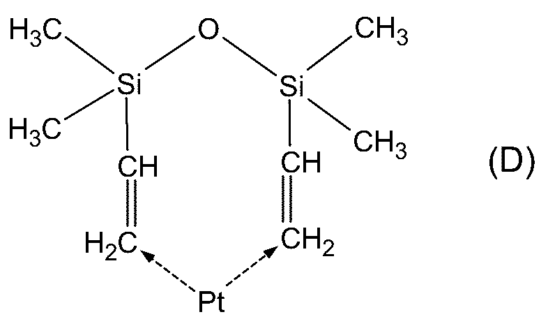
(液晶性シリコーンエラストマーの特性)
(1)液晶構造の確認
偏光顕微鏡を用いて得られた液晶性シリコーンエラストマーの液晶構造を確認したところ、この液晶性シリコーンエラストマーはスメクチック相を示すことが明らかとなった。
(1)液晶構造の確認
偏光顕微鏡を用いて得られた液晶性シリコーンエラストマーの液晶構造を確認したところ、この液晶性シリコーンエラストマーはスメクチック相を示すことが明らかとなった。
(2)熱伝導率の測定
ASTM C518およびJIS A 1412-2に準拠する熱流計法(HFM法)によって上記液晶性シリコーンエラストマーの熱伝導率を測定したところ、その熱伝導率は0.737W/m・Kであった。
ASTM C518およびJIS A 1412-2に準拠する熱流計法(HFM法)によって上記液晶性シリコーンエラストマーの熱伝導率を測定したところ、その熱伝導率は0.737W/m・Kであった。
(3)硬度測定
JIS K6253に記載の硬度測定方法に則って上記液晶性シリコーンエラストマーのデュロメータ硬さタイプAを測定したところ、その硬度は30であった。
JIS K6253に記載の硬度測定方法に則って上記液晶性シリコーンエラストマーのデュロメータ硬さタイプAを測定したところ、その硬度は30であった。
(シームレス定着管状物の作製)
表面が離型処理された円筒金型の表面に、ポリアミック酸溶液(組成:3,3’,4,4’-ビフェニルテトラカルボン酸二無水物(以下「BPDA」と略する。)/パラフェニレンジアミン(以下「PPD」と略する。),固形分:17.0質量%)を均一に塗布した後、その塗膜を100℃で10分間、150℃で20分間、250℃で30分間、400℃で15分間の条件で順に加熱して、厚み60μmのポリイミド管状物Aを得た。
表面が離型処理された円筒金型の表面に、ポリアミック酸溶液(組成:3,3’,4,4’-ビフェニルテトラカルボン酸二無水物(以下「BPDA」と略する。)/パラフェニレンジアミン(以下「PPD」と略する。),固形分:17.0質量%)を均一に塗布した後、その塗膜を100℃で10分間、150℃で20分間、250℃で30分間、400℃で15分間の条件で順に加熱して、厚み60μmのポリイミド管状物Aを得た。
次に、ポリイミド管状物Aの表面に、プライマー液を塗布し、その塗膜を150℃で10分間加熱した。そして、プライマー液塗布部分に上記液晶性シリコーンエラストマーを均一に塗布した後、150℃で30分間、200℃で30分間の条件で順に加熱して液晶性シリコーンゴムの加硫を行って厚み300μmの弾性層を形成した。
次いで、弾性層の外表面にプライマー液を塗布し、その塗膜を150℃で10分間加熱した。そして、プライマー塗布部分にフッ素樹脂分散液を均一に塗布した後、その塗膜を60℃で10分間乾燥し、さらに340℃で10分間焼成して厚み20μmの離型層を形成した。その結果、厚み382μm、内径18.00mm、長さ390mmのシームレス定着管状物を得た。
このシームレス定着管状物をカラーレーザープリンターの定着装置に装着し、カラー印刷を行ったところ、トナーの定着状態も良好で、良質な画像が得られた。
<実施例2>
(液晶性シリコーンエラストマーの合成)において200℃での加熱時間を0.75時間(45分間)に代えた以外は、実施例1と同様にして液晶性シリコーンエラストマーを得、実施例1と同様にしてその液晶性シリコーンエラストマーの特性を評価した。
(液晶性シリコーンエラストマーの合成)において200℃での加熱時間を0.75時間(45分間)に代えた以外は、実施例1と同様にして液晶性シリコーンエラストマーを得、実施例1と同様にしてその液晶性シリコーンエラストマーの特性を評価した。
この液晶性シリコーンエラストマーはスメクチック相を示した。また、この液晶性シリコーンエラストマーの熱伝導率は0.475W/m・Kであった。さらに、この液晶性シリコーンエラストマーの硬度は45であった。
また、上記液晶性シリコーンエラストマーを用いた以外は、実施例1と同様にしてシームレス定着管状物を得た。そして、このシームレス定着管状物をカラーレーザープリンターの定着装置に装着し、カラー印刷を行ったところ、トナーの定着状態も良好で、良質な画像が得られた。
<実施例3>
(液晶性シリコーンエラストマーの合成)において200℃での加熱時間を1時間に代えた以外は、実施例1と同様にして液晶性シリコーンエラストマーを得、実施例1と同様にしてその液晶性シリコーンエラストマーの特性を評価した。
(液晶性シリコーンエラストマーの合成)において200℃での加熱時間を1時間に代えた以外は、実施例1と同様にして液晶性シリコーンエラストマーを得、実施例1と同様にしてその液晶性シリコーンエラストマーの特性を評価した。
この液晶性シリコーンエラストマーはスメクチック相を示した。また、この液晶性シリコーンエラストマーの熱伝導率は0.290W/m・Kであった。さらに、この液晶性シリコーンエラストマーの硬度は47であった。
また、上記液晶性シリコーンエラストマーを用いた以外は、実施例1と同様にしてシームレス定着管状物を得た。そして、このシームレス定着管状物をカラーレーザープリンターの定着装置に装着し、カラー印刷を行ったところ、トナーの定着状態も良好で、良質な画像が得られた。
<実施例4>
(液晶性シリコーンエラストマーの合成)において200℃での加熱時間を3時間に代えた以外は、実施例1と同様にして液晶性シリコーンエラストマーを得、実施例1と同様にしてその液晶性シリコーンエラストマーの特性を評価した。
(液晶性シリコーンエラストマーの合成)において200℃での加熱時間を3時間に代えた以外は、実施例1と同様にして液晶性シリコーンエラストマーを得、実施例1と同様にしてその液晶性シリコーンエラストマーの特性を評価した。
この液晶性シリコーンエラストマーはスメクチック相を示した。また、この液晶性シリコーンエラストマーの熱伝導率は0.284W/m・Kであった。さらに、この液晶性シリコーンエラストマーの硬度は64であった。
また、上記液晶性シリコーンエラストマーを用いた以外は、実施例1と同様にしてシームレス定着管状物を得た。そして、このシームレス定着管状物をカラーレーザープリンターの定着装置に装着し、カラー印刷を行ったところ、トナーの定着状態も良好で、良質な画像が得られた。
<実施例5>
(液晶性シリコーンエラストマーの合成)において200℃での加熱時間を5時間に代えた以外は、実施例1と同様にして液晶性シリコーンエラストマーを得、実施例1と同様にしてその液晶性シリコーンエラストマーの特性を評価した。
(液晶性シリコーンエラストマーの合成)において200℃での加熱時間を5時間に代えた以外は、実施例1と同様にして液晶性シリコーンエラストマーを得、実施例1と同様にしてその液晶性シリコーンエラストマーの特性を評価した。
この液晶性シリコーンエラストマーはスメクチック相を示した。また、この液晶性シリコーンエラストマーの熱伝導率は0.212W/m・Kであった。さらに、この液晶性シリコーンエラストマーの硬度は71であった。
また、上記液晶性シリコーンエラストマーを用いた以外は、実施例1と同様にしてシームレス定着管状物を得た。そして、このシームレス定着管状物をカラーレーザープリンターの定着装置に装着し、カラー印刷を行ったところ、トナーの定着状態も良好で、良質な画像が得られた。
<実施例6>
(液晶性シリコーンエラストマーの合成)において反応抑制剤の添加量を400μLに代え、200℃での加熱時間を1時間に代えた以外は、実施例1と同様にして液晶性シリコーンエラストマーを得、実施例1と同様にしてその液晶性シリコーンエラストマーの特性を評価した。
(液晶性シリコーンエラストマーの合成)において反応抑制剤の添加量を400μLに代え、200℃での加熱時間を1時間に代えた以外は、実施例1と同様にして液晶性シリコーンエラストマーを得、実施例1と同様にしてその液晶性シリコーンエラストマーの特性を評価した。
この液晶性シリコーンエラストマーはスメクチック相を示した。また、この液晶性シリコーンエラストマーの熱伝導率は0.275W/m・Kであった。さらに、この液晶性シリコーンエラストマーの硬度は58であった。
また、上記液晶性シリコーンエラストマーを用いた以外は、実施例1と同様にしてシームレス定着管状物を得た。そして、このシームレス定着管状物をカラーレーザープリンターの定着装置に装着し、カラー印刷を行ったところ、トナーの定着状態も良好で、良質な画像が得られた。
<実施例7>
(液晶性シリコーンエラストマーの合成)において反応抑制剤の添加量を200μLに代え、200℃での加熱時間を1時間に代えた以外は、実施例1と同様にして液晶性シリコーンエラストマーを得、実施例1と同様にしてその液晶性シリコーンエラストマーの特性を評価した。
(液晶性シリコーンエラストマーの合成)において反応抑制剤の添加量を200μLに代え、200℃での加熱時間を1時間に代えた以外は、実施例1と同様にして液晶性シリコーンエラストマーを得、実施例1と同様にしてその液晶性シリコーンエラストマーの特性を評価した。
この液晶性シリコーンエラストマーはスメクチック相を示した。また、この液晶性シリコーンエラストマーの熱伝導率は0.345W/m・Kであった。さらに、この液晶性シリコーンエラストマーの硬度は48であった。
また、上記液晶性シリコーンエラストマーを用いた以外は、実施例1と同様にしてシームレス定着管状物を得た。そして、このシームレス定着管状物をカラーレーザープリンターの定着装置に装着し、カラー印刷を行ったところ、トナーの定着状態も良好で、良質な画像が得られた。
<実施例8>
(液晶性シリコーンエラストマーの合成)において白金触媒Pt(dvs)の添加量を0.5gに代え、200℃での加熱時間を1時間に代えた以外は、実施例1と同様にして液晶性シリコーンエラストマーを得、実施例1と同様にしてその液晶性シリコーンエラストマーの特性を評価した。
(液晶性シリコーンエラストマーの合成)において白金触媒Pt(dvs)の添加量を0.5gに代え、200℃での加熱時間を1時間に代えた以外は、実施例1と同様にして液晶性シリコーンエラストマーを得、実施例1と同様にしてその液晶性シリコーンエラストマーの特性を評価した。
この液晶性シリコーンエラストマーはスメクチック相を示した。また、この液晶性シリコーンエラストマーの熱伝導率は0.234W/m・Kであった。さらに、この液晶性シリコーンエラストマーの硬度は82であった。
また、上記液晶性シリコーンエラストマーを用いた以外は、実施例1と同様にしてシームレス定着管状物を得た。そして、このシームレス定着管状物をカラーレーザープリンターの定着装置に装着し、カラー印刷を行ったところ、トナーの定着状態も良好で、良質な画像が得られた。
<実施例9>
(液晶性シリコーンエラストマーの合成)において白金触媒Pt(dvs)の添加量を0.01gに代え、200℃での加熱時間を1時間に代えた以外は、実施例1と同様にして液晶性シリコーンエラストマーを得、実施例1と同様にしてその液晶性シリコーンエラストマーの特性を評価した。
(液晶性シリコーンエラストマーの合成)において白金触媒Pt(dvs)の添加量を0.01gに代え、200℃での加熱時間を1時間に代えた以外は、実施例1と同様にして液晶性シリコーンエラストマーを得、実施例1と同様にしてその液晶性シリコーンエラストマーの特性を評価した。
この液晶性シリコーンエラストマーはスメクチック相を示した。また、この液晶性シリコーンエラストマーの熱伝導率は0.854W/m・Kであった。さらに、この液晶性シリコーンエラストマーの硬度は15であった。
また、上記液晶性シリコーンエラストマーを用いた以外は、実施例1と同様にしてシームレス定着管状物を得た。そして、このシームレス定着管状物をカラーレーザープリンターの定着装置に装着し、カラー印刷を行ったところ、トナーの定着状態も良好で、良質な画像が得られた。
<実施例10>
(液晶性シリコーンポリマーの合成)において4-シアノ-4’-(4-ペント-4-エノキシ)-1,1’-ビフェニルの添加量を12.9g(49.0mmol)に代え、ポリメチルヒドロシロキサンの添加量を5gに代えて液晶性シリコーンポリマー(メソゲン基導入率約50%)を得、(液晶性シリコーンエラストマーの合成)において200℃での加熱時間を1時間に代えた以外は、実施例1と同様にして液晶性シリコーンエラストマーを得、実施例1と同様にしてその液晶性シリコーンエラストマーの特性を評価した。
(液晶性シリコーンポリマーの合成)において4-シアノ-4’-(4-ペント-4-エノキシ)-1,1’-ビフェニルの添加量を12.9g(49.0mmol)に代え、ポリメチルヒドロシロキサンの添加量を5gに代えて液晶性シリコーンポリマー(メソゲン基導入率約50%)を得、(液晶性シリコーンエラストマーの合成)において200℃での加熱時間を1時間に代えた以外は、実施例1と同様にして液晶性シリコーンエラストマーを得、実施例1と同様にしてその液晶性シリコーンエラストマーの特性を評価した。
この液晶性シリコーンエラストマーはスメクチック相を示した。また、この液晶性シリコーンエラストマーの熱伝導率は0.351W/m・Kであった。さらに、この液晶性シリコーンエラストマーの硬度は70であった。
また、上記液晶性シリコーンエラストマーを用いた以外は、実施例1と同様にしてシームレス定着管状物を得た。そして、このシームレス定着管状物をカラーレーザープリンターの定着装置に装着し、カラー印刷を行ったところ、トナーの定着状態も良好で、良質な画像が得られた。
<実施例11>
(液晶性シリコーンポリマーの合成)において4-シアノ-4’-(4-ペント-4-エノキシ)-1,1’-ビフェニルの添加量を7.75g(29.4mmol)に代え、ポリメチルヒドロシロキサンの添加量を5gに代えて液晶性シリコーンポリマー(メソゲン基導入率約37%)を得、(液晶性シリコーンエラストマーの合成)において200℃での加熱時間を1時間に代えた以外は、実施例1と同様にして液晶性シリコーンエラストマーを得、実施例1と同様にしてその液晶性シリコーンエラストマーの特性を評価した。
(液晶性シリコーンポリマーの合成)において4-シアノ-4’-(4-ペント-4-エノキシ)-1,1’-ビフェニルの添加量を7.75g(29.4mmol)に代え、ポリメチルヒドロシロキサンの添加量を5gに代えて液晶性シリコーンポリマー(メソゲン基導入率約37%)を得、(液晶性シリコーンエラストマーの合成)において200℃での加熱時間を1時間に代えた以外は、実施例1と同様にして液晶性シリコーンエラストマーを得、実施例1と同様にしてその液晶性シリコーンエラストマーの特性を評価した。
この液晶性シリコーンエラストマーはスメクチック相を示した。また、この液晶性シリコーンエラストマーの熱伝導率は0.289W/m・Kであった。さらに、この液晶性シリコーンエラストマーの硬度は60であった。
また、上記液晶性シリコーンエラストマーを用いた以外は、実施例1と同様にしてシームレス定着管状物を得た。そして、このシームレス定着管状物をカラーレーザープリンターの定着装置に装着し、カラー印刷を行ったところ、トナーの定着状態も良好で、良質な画像が得られた。
<実施例12>
(液晶性シリコーンポリマーの合成)において4-シアノ-4’-(4-ペント-4-エノキシ)-1,1’-ビフェニルの添加量を12.9g(49.0mmol)に代え、ポリメチルヒドロシロキサンの添加量を5gに代えて液晶性シリコーンポリマー(メソゲン基導入率約50%)を得、(液晶性シリコーンエラストマーの合成)において白金触媒Pt(dvs)の添加量を0.01gに代え、硬化助剤として1-ドデセン0.086gをさらに加え、200℃での加熱時間を3時間に代えた以外は、実施例1と同様にして液晶性シリコーンエラストマーを得、実施例1と同様にしてその液晶性シリコーンエラストマーの特性を評価した。
(液晶性シリコーンポリマーの合成)において4-シアノ-4’-(4-ペント-4-エノキシ)-1,1’-ビフェニルの添加量を12.9g(49.0mmol)に代え、ポリメチルヒドロシロキサンの添加量を5gに代えて液晶性シリコーンポリマー(メソゲン基導入率約50%)を得、(液晶性シリコーンエラストマーの合成)において白金触媒Pt(dvs)の添加量を0.01gに代え、硬化助剤として1-ドデセン0.086gをさらに加え、200℃での加熱時間を3時間に代えた以外は、実施例1と同様にして液晶性シリコーンエラストマーを得、実施例1と同様にしてその液晶性シリコーンエラストマーの特性を評価した。
この液晶性シリコーンエラストマーはスメクチック相を示した。また、この液晶性シリコーンエラストマーの熱伝導率は1.07W/m・Kであった。
また、上記液晶性シリコーンエラストマーを用いた以外は、実施例1と同様にしてシームレス定着管状物を得た。そして、このシームレス定着管状物をカラーレーザープリンターの定着装置に装着し、カラー印刷を行ったところ、トナーの定着状態も良好で、良質な画像が得られた。
<実施例13>
200℃での加熱時間を5時間に代えた以外は、実施例12と同様にして液晶性シリコーンエラストマーを得、実施例1と同様にしてその液晶性シリコーンエラストマーの特性を評価した。
200℃での加熱時間を5時間に代えた以外は、実施例12と同様にして液晶性シリコーンエラストマーを得、実施例1と同様にしてその液晶性シリコーンエラストマーの特性を評価した。
この液晶性シリコーンエラストマーはスメクチック相を示した。また、この液晶性シリコーンエラストマーの熱伝導率は0.505W/m・Kであった。
また、上記液晶性シリコーンエラストマーを用いた以外は、実施例1と同様にしてシームレス定着管状物を得た。そして、このシームレス定着管状物をカラーレーザープリンターの定着装置に装着し、カラー印刷を行ったところ、トナーの定着状態も良好で、良質な画像が得られた。
<実施例14>
(液晶性シリコーンポリマーの合成)において4-シアノ-4’-(4-ペント-4-エノキシ)-1,1’-ビフェニルの添加量を12.9g(49.0mmol)に代え、ポリメチルヒドロシロキサンの添加量を5gに代えて液晶性シリコーンポリマー(メソゲン基導入率約50%)を得、(液晶性シリコーンエラストマーの合成)において化学式(C)の反応抑制剤を下記化学式(E)のメチルブチノールに代え、白金触媒Pt(dvs)の添加量を0.01gに代え、200℃での加熱時間を3時間に代えた以外は、実施例1と同様にして液晶性シリコーンエラストマーを得、実施例1と同様にしてその液晶性シリコーンエラストマーの特性を評価した。
(液晶性シリコーンポリマーの合成)において4-シアノ-4’-(4-ペント-4-エノキシ)-1,1’-ビフェニルの添加量を12.9g(49.0mmol)に代え、ポリメチルヒドロシロキサンの添加量を5gに代えて液晶性シリコーンポリマー(メソゲン基導入率約50%)を得、(液晶性シリコーンエラストマーの合成)において化学式(C)の反応抑制剤を下記化学式(E)のメチルブチノールに代え、白金触媒Pt(dvs)の添加量を0.01gに代え、200℃での加熱時間を3時間に代えた以外は、実施例1と同様にして液晶性シリコーンエラストマーを得、実施例1と同様にしてその液晶性シリコーンエラストマーの特性を評価した。

この液晶性シリコーンエラストマーはスメクチック相を示した。また、この液晶性シリコーンエラストマーの熱伝導率は0.366W/m・Kであった。
また、上記液晶性シリコーンエラストマーを用いた以外は、実施例1と同様にしてシームレス定着管状物を得た。そして、このシームレス定着管状物をカラーレーザープリンターの定着装置に装着し、カラー印刷を行ったところ、トナーの定着状態も良好で、良質な画像が得られた。
<実施例15>
メチルブチノールの添加量を30μLに代えた以外は、実施例14と同様にして液晶性シリコーンエラストマーを得、実施例1と同様にしてその液晶性シリコーンエラストマーの特性を評価した。
メチルブチノールの添加量を30μLに代えた以外は、実施例14と同様にして液晶性シリコーンエラストマーを得、実施例1と同様にしてその液晶性シリコーンエラストマーの特性を評価した。
この液晶性シリコーンエラストマーはスメクチック相を示した。また、この液晶性シリコーンエラストマーの熱伝導率は0.455W/m・Kであった。
また、上記液晶性シリコーンエラストマーを用いた以外は、実施例1と同様にしてシームレス定着管状物を得た。そして、このシームレス定着管状物をカラーレーザープリンターの定着装置に装着し、カラー印刷を行ったところ、トナーの定着状態も良好で、良質な画像が得られた。
<実施例16>
(液晶性シリコーンエラストマーの合成)において化学式(C)の反応抑制剤を下記化学式(E)のメチルブチノールに代えた以外は、実施例12と同様にして液晶性シリコーンエラストマーを得、実施例1と同様にしてその液晶性シリコーンエラストマーの特性を評価した。
(液晶性シリコーンエラストマーの合成)において化学式(C)の反応抑制剤を下記化学式(E)のメチルブチノールに代えた以外は、実施例12と同様にして液晶性シリコーンエラストマーを得、実施例1と同様にしてその液晶性シリコーンエラストマーの特性を評価した。
この液晶性シリコーンエラストマーはスメクチック相を示した。また、この液晶性シリコーンエラストマーの熱伝導率は0.449W/m・Kであった。
また、上記液晶性シリコーンエラストマーを用いた以外は、実施例1と同様にしてシームレス定着管状物を得た。そして、このシームレス定着管状物をカラーレーザープリンターの定着装置に装着し、カラー印刷を行ったところ、トナーの定着状態も良好で、良質な画像が得られた。
<実施例17>
(液晶性シリコーンポリマーの合成)において4-シアノ-4’-(4-ペント-4-エノキシ)-1,1’-ビフェニルの添加量を7.7g(29.3mmol)に代え、ポリメチルヒドロシロキサンの添加量を5.0gに代えて液晶性シリコーンポリマー(メソゲン基導入率約30%)を得、(液晶性シリコーンエラストマーの合成)において200℃での加熱時間を5時間に代えた以外は、実施例1と同様にして液晶性シリコーンエラストマーを得、実施例1と同様にしてその液晶性シリコーンエラストマーの特性を評価した。
(液晶性シリコーンポリマーの合成)において4-シアノ-4’-(4-ペント-4-エノキシ)-1,1’-ビフェニルの添加量を7.7g(29.3mmol)に代え、ポリメチルヒドロシロキサンの添加量を5.0gに代えて液晶性シリコーンポリマー(メソゲン基導入率約30%)を得、(液晶性シリコーンエラストマーの合成)において200℃での加熱時間を5時間に代えた以外は、実施例1と同様にして液晶性シリコーンエラストマーを得、実施例1と同様にしてその液晶性シリコーンエラストマーの特性を評価した。
この液晶性シリコーンエラストマーはスメクチック相を示した。また、この液晶性シリコーンエラストマーの熱伝導率は0.443W/m・Kであった。
また、上記液晶性シリコーンエラストマーを用いた以外は、実施例1と同様にしてシームレス定着管状物を得た。そして、このシームレス定着管状物をカラーレーザープリンターの定着装置に装着し、カラー印刷を行ったところ、トナーの定着状態も良好で、良質な画像が得られた。
<実施例18>
(液晶性シリコーンポリマーの合成)において4-シアノ-4’-(4-ペント-4-エノキシ)-1,1’-ビフェニルの添加量を10.2g(38.8mmol)に代え、ポリメチルヒドロシロキサンの添加量を5.0gに代えて液晶性シリコーンポリマー(メソゲン基導入率約40%)を得、(液晶性シリコーンエラストマーの合成)において200℃での加熱時間を5時間に代えた以外は、実施例1と同様にして液晶性シリコーンエラストマーを得、実施例1と同様にしてその液晶性シリコーンエラストマーの特性を評価した。
(液晶性シリコーンポリマーの合成)において4-シアノ-4’-(4-ペント-4-エノキシ)-1,1’-ビフェニルの添加量を10.2g(38.8mmol)に代え、ポリメチルヒドロシロキサンの添加量を5.0gに代えて液晶性シリコーンポリマー(メソゲン基導入率約40%)を得、(液晶性シリコーンエラストマーの合成)において200℃での加熱時間を5時間に代えた以外は、実施例1と同様にして液晶性シリコーンエラストマーを得、実施例1と同様にしてその液晶性シリコーンエラストマーの特性を評価した。
この液晶性シリコーンエラストマーはスメクチック相を示した。また、この液晶性シリコーンエラストマーの熱伝導率は0.447W/m・Kであった。
また、上記液晶性シリコーンエラストマーを用いた以外は、実施例1と同様にしてシームレス定着管状物を得た。そして、このシームレス定着管状物をカラーレーザープリンターの定着装置に装着し、カラー印刷を行ったところ、トナーの定着状態も良好で、良質な画像が得られた。
<実施例19>
(液晶性シリコーンポリマーの合成)において4-シアノ-4’-(4-ペント-4-エノキシ)-1,1’-ビフェニルの添加量を62.3g(2.35mmol)に代え、ポリメチルヒドロシロキサンの添加量を24.1gに代えて液晶性シリコーンポリマー(メソゲン基導入率約60%)を得、(液晶性シリコーンエラストマーの合成)において200℃での加熱時間を5時間に代えた以外は、実施例1と同様にして液晶性シリコーンエラストマーを得、実施例1と同様にしてその液晶性シリコーンエラストマーの特性を評価した。
(液晶性シリコーンポリマーの合成)において4-シアノ-4’-(4-ペント-4-エノキシ)-1,1’-ビフェニルの添加量を62.3g(2.35mmol)に代え、ポリメチルヒドロシロキサンの添加量を24.1gに代えて液晶性シリコーンポリマー(メソゲン基導入率約60%)を得、(液晶性シリコーンエラストマーの合成)において200℃での加熱時間を5時間に代えた以外は、実施例1と同様にして液晶性シリコーンエラストマーを得、実施例1と同様にしてその液晶性シリコーンエラストマーの特性を評価した。
この液晶性シリコーンエラストマーはスメクチック相を示した。また、この液晶性シリコーンエラストマーの熱伝導率は0.467W/m・Kであった。
また、上記液晶性シリコーンエラストマーを用いた以外は、実施例1と同様にしてシームレス定着管状物を得た。そして、このシームレス定着管状物をカラーレーザープリンターの定着装置に装着し、カラー印刷を行ったところ、トナーの定着状態も良好で、良質な画像が得られた。
<実施例20>
(液晶性シリコーンポリマーの合成)において4-シアノ-4’-(4-ペント-4-エノキシ)-1,1’-ビフェニル16.1g(61.2mmol)を下記化学式(2)の(4-シアノフェニル)-4-ペント-4-エノキシベンゾアート0.689g(2.25mmol)に代え、ポリメチルヒドロシロキサンの添加量を0.5gに代えて液晶性シリコーンポリマー(メソゲン基導入率約20%)を得、(液晶性シリコーンエラストマーの合成)において200℃での加熱時間を1時間に代えた以外は、実施例1と同様にして液晶性シリコーンエラストマーを得、実施例1と同様にしてその液晶性シリコーンエラストマーの特性を評価した。
(液晶性シリコーンポリマーの合成)において4-シアノ-4’-(4-ペント-4-エノキシ)-1,1’-ビフェニル16.1g(61.2mmol)を下記化学式(2)の(4-シアノフェニル)-4-ペント-4-エノキシベンゾアート0.689g(2.25mmol)に代え、ポリメチルヒドロシロキサンの添加量を0.5gに代えて液晶性シリコーンポリマー(メソゲン基導入率約20%)を得、(液晶性シリコーンエラストマーの合成)において200℃での加熱時間を1時間に代えた以外は、実施例1と同様にして液晶性シリコーンエラストマーを得、実施例1と同様にしてその液晶性シリコーンエラストマーの特性を評価した。

この液晶性シリコーンエラストマーはスメクチック相を示した。また、この液晶性シリコーンエラストマーの熱伝導率は0.315W/m・Kであった。
また、上記液晶性シリコーンエラストマーを用いた以外は、実施例1と同様にしてシームレス定着管状物を得た。そして、このシームレス定着管状物をカラーレーザープリンターの定着装置に装着し、カラー印刷を行ったところ、トナーの定着状態も良好で、良質な画像が得られた。
<実施例21>
(液晶性シリコーンポリマーの合成)において(4-シアノフェニル)-4-ペント-4-エノキシベンゾアートの添加量を1.04g(3.39mmol)に代えて液晶性シリコーンポリマー(メソゲン基導入率約30%)を得た以外は、実施例20と同様にして液晶性シリコーンエラストマーを得、実施例1と同様にしてその液晶性シリコーンエラストマーの特性を評価した。
(液晶性シリコーンポリマーの合成)において(4-シアノフェニル)-4-ペント-4-エノキシベンゾアートの添加量を1.04g(3.39mmol)に代えて液晶性シリコーンポリマー(メソゲン基導入率約30%)を得た以外は、実施例20と同様にして液晶性シリコーンエラストマーを得、実施例1と同様にしてその液晶性シリコーンエラストマーの特性を評価した。
この液晶性シリコーンエラストマーはスメクチック相を示した。また、この液晶性シリコーンエラストマーの熱伝導率は0.378W/m・Kであった。
また、上記液晶性シリコーンエラストマーを用いた以外は、実施例1と同様にしてシームレス定着管状物を得た。そして、このシームレス定着管状物をカラーレーザープリンターの定着装置に装着し、カラー印刷を行ったところ、トナーの定着状態も良好で、良質な画像が得られた。
<実施例22>
(液晶性シリコーンポリマーの合成)において(4-シアノフェニル)-4-ペント-4-エノキシベンゾアートの添加量を1.38g(4.50mmol)に代えて液晶性シリコーンポリマー(メソゲン基導入率約40%)を得た以外は、実施例20と同様にして液晶性シリコーンエラストマーを得、実施例1と同様にしてその液晶性シリコーンエラストマーの特性を評価した。
(液晶性シリコーンポリマーの合成)において(4-シアノフェニル)-4-ペント-4-エノキシベンゾアートの添加量を1.38g(4.50mmol)に代えて液晶性シリコーンポリマー(メソゲン基導入率約40%)を得た以外は、実施例20と同様にして液晶性シリコーンエラストマーを得、実施例1と同様にしてその液晶性シリコーンエラストマーの特性を評価した。
この液晶性シリコーンエラストマーはスメクチック相を示した。また、この液晶性シリコーンエラストマーの熱伝導率は1.134W/m・Kであった。
また、上記液晶性シリコーンエラストマーを用いた以外は、実施例1と同様にしてシームレス定着管状物を得た。そして、このシームレス定着管状物をカラーレーザープリンターの定着装置に装着し、カラー印刷を行ったところ、トナーの定着状態も良好で、良質な画像が得られた。
<実施例23>
(液晶性シリコーンポリマーの合成)において(4-シアノフェニル)-4-ペント-4-エノキシベンゾアートの添加量を1.73g(5.64mmol)に代えて液晶性シリコーンポリマー(メソゲン基導入率約50%)を得た以外は、実施例20と同様にして液晶性シリコーンエラストマーを得、実施例1と同様にしてその液晶性シリコーンエラストマーの特性を評価した。
(液晶性シリコーンポリマーの合成)において(4-シアノフェニル)-4-ペント-4-エノキシベンゾアートの添加量を1.73g(5.64mmol)に代えて液晶性シリコーンポリマー(メソゲン基導入率約50%)を得た以外は、実施例20と同様にして液晶性シリコーンエラストマーを得、実施例1と同様にしてその液晶性シリコーンエラストマーの特性を評価した。
この液晶性シリコーンエラストマーはスメクチック相を示した。また、この液晶性シリコーンエラストマーの熱伝導率は0.989W/m・Kであった。
また、上記液晶性シリコーンエラストマーを用いた以外は、実施例1と同様にしてシームレス定着管状物を得た。そして、このシームレス定着管状物をカラーレーザープリンターの定着装置に装着し、カラー印刷を行ったところ、トナーの定着状態も良好で、良質な画像が得られた。
<実施例24>
(液晶性シリコーンポリマーの合成)において4-シアノ-4’-(4-ペント-4-エノキシ)-1,1’-ビフェニル16.1g(61.2mmol)を下記化学式(1)の(4-メトキシフェニル)-4-ペント-4-エノキシベンゾアート12.1g(38.7mmol)に代え、ポリメチルヒドロシロキサンの添加量を5.0gに代えて液晶性シリコーンポリマー(メソゲン基導入率約30%)を得、(液晶性シリコーンエラストマーの合成)において200℃での加熱時間を5時間に代えた以外は、実施例1と同様にして液晶性シリコーンエラストマーを得、実施例1と同様にしてその液晶性シリコーンエラストマーの特性を評価した。
(液晶性シリコーンポリマーの合成)において4-シアノ-4’-(4-ペント-4-エノキシ)-1,1’-ビフェニル16.1g(61.2mmol)を下記化学式(1)の(4-メトキシフェニル)-4-ペント-4-エノキシベンゾアート12.1g(38.7mmol)に代え、ポリメチルヒドロシロキサンの添加量を5.0gに代えて液晶性シリコーンポリマー(メソゲン基導入率約30%)を得、(液晶性シリコーンエラストマーの合成)において200℃での加熱時間を5時間に代えた以外は、実施例1と同様にして液晶性シリコーンエラストマーを得、実施例1と同様にしてその液晶性シリコーンエラストマーの特性を評価した。

この液晶性シリコーンエラストマーはネマチック相を示した(ただし、液晶性シリコーンポリマーではスメクチック相を示した。)。また、この液晶性シリコーンエラストマーの熱伝導率は0.517W/m・Kであった。
また、上記液晶性シリコーンエラストマーを用いた以外は、実施例1と同様にしてシームレス定着管状物を得た。そして、このシームレス定着管状物をカラーレーザープリンターの定着装置に装着し、カラー印刷を行ったところ、トナーの定着状態も良好で、良質な画像が得られた。
以上の実施例の結果を以下の表1にまとめた。

なお、上表中、「PMHS」は化学式(A)のポリメチルヒドロシロキサン(重合度:26~51,重量平均分子量(Mw):1700~3200)を示し、「MSGN」はビニル基含有メソゲン化合物を示し、「Pt/C」は白金触媒を示し、「LCT」は液晶性シリコーンポリマーを示し、「CR」は化学式(B)の架橋剤を示し、「CT」は化学式(D)の白金触媒を示し、「DDC」は1-ドデセンを示し、「RI」は反応抑制剤を示し、「DMHO」は化学式(C)の3,5-ジメチル-1-ヘキシン-3-オールを示し、「MB」は化学式(E)のメチルブチノールを示し、「t@200℃」は200℃での加熱時間を示し、「Sm」はスメクチック相を示し、「N」はネマチック相を示す。
<実施例25>
(液晶性シリコーンポリマーの合成)
実施例1における4-シアノ-4’-(4-ペント-4-エノキシ)-1,1’-ビフェニル62.3g(2.35mmol)と、実施例1における化学式(A)のポリメチルヒドロシロキサン(重合度:26~51,重量平均分子量(Mw):1700~3200)24.1gとを200mLのトルエンに溶解させた(以下、この溶液を「溶液A」という)。また、触媒量の白金触媒Pt/Cを2-プロパノール中に分散させた(以下、この分散液を「分散液B」という)。そして、溶液Aに分散液Bを添加した後、その混合液の温度を110℃に調節した。その後、その混合液を110℃に保ったまま24時間撹拌した。撹拌完了後、ロータリーエバポレーターを用いて混合液から溶媒を留去し、粗化合物を得た。次に、その粗化合物をアセトンに溶解した。続いて、粗化合物のアセトン溶液に、粗化合物の貧溶媒であるエタノールを加えて、粗化合物を再沈殿させた。さらに、その再沈殿操作を3回行った後、沈殿物を回収して液晶性シリコーンポリマーを得た。なお、ポリメチルヒドロシロキサンに対するメソゲン基の導入率は約60%であった。
(フィラー入り液晶性シリコーンエラストマーの調製)
上述の通りにして得られた液晶性シリコーンポリマー1.0gに対して、実施例1における化学式(B)の架橋剤0.1g、実施例1における化学式(C)の反応抑制剤300μLおよび実施例1における化学式(D)の白金触媒Pt(dvs)0.1mLを添加した後、それらをよく混合した。そして、その混合物を100℃まで加熱した後、そこに0.208gの金属ケイ素(キンセイマテック社製,M-Si #600,7μm)を加えて撹拌混合した。続けて、その混合物を3本ロールミルに3回通してさらに混練した。その後、その混合物を150℃で0.5時間(30分間)加熱し、さらに200℃で5時間加熱し、フィラー入り液晶性シリコーンエラストマーを得た。なお、このフィラー入り液晶性シリコーンエラストマー中の金属ケイ素含有量は20質量%(10体積%)であった。
上述の通りにして得られた液晶性シリコーンポリマー1.0gに対して、実施例1における化学式(B)の架橋剤0.1g、実施例1における化学式(C)の反応抑制剤300μLおよび実施例1における化学式(D)の白金触媒Pt(dvs)0.1mLを添加した後、それらをよく混合した。そして、その混合物を100℃まで加熱した後、そこに0.208gの金属ケイ素(キンセイマテック社製,M-Si #600,7μm)を加えて撹拌混合した。続けて、その混合物を3本ロールミルに3回通してさらに混練した。その後、その混合物を150℃で0.5時間(30分間)加熱し、さらに200℃で5時間加熱し、フィラー入り液晶性シリコーンエラストマーを得た。なお、このフィラー入り液晶性シリコーンエラストマー中の金属ケイ素含有量は20質量%(10体積%)であった。
(フィラー入り液晶性シリコーンエラストマーの熱伝導率の測定)
実施例1と同様にしてこのフィラー入り液晶性シリコーンエラストマーの熱伝導率を測定したところ、その熱伝導率は0.595W/m・Kであった。
実施例1と同様にしてこのフィラー入り液晶性シリコーンエラストマーの熱伝導率を測定したところ、その熱伝導率は0.595W/m・Kであった。
(シームレス定着管状物の作製)
上記液晶性シリコーンエラストマーを用いた以外は、実施例1と同様にしてシームレス定着管状物を得た。そして、このシームレス定着管状物をカラーレーザープリンターの定着装置に装着し、カラー印刷を行ったところ、トナーの定着状態も良好で、良質な画像が得られた。
上記液晶性シリコーンエラストマーを用いた以外は、実施例1と同様にしてシームレス定着管状物を得た。そして、このシームレス定着管状物をカラーレーザープリンターの定着装置に装着し、カラー印刷を行ったところ、トナーの定着状態も良好で、良質な画像が得られた。
<実施例26>
金属ケイ素の添加量を0.356gに代えた以外は、実施例24と同様にしてフィラー入り液晶性シリコーンエラストマーを調製した。なお、このフィラー入り液晶性シリコーンエラストマー中の金属ケイ素含有量は30質量%(15体積%)であった。また、実施例1と同様にしてこのフィラー入り液晶性シリコーンエラストマーの熱伝導率を測定したところ、その熱伝導率は0.771W/m・Kであった。
金属ケイ素の添加量を0.356gに代えた以外は、実施例24と同様にしてフィラー入り液晶性シリコーンエラストマーを調製した。なお、このフィラー入り液晶性シリコーンエラストマー中の金属ケイ素含有量は30質量%(15体積%)であった。また、実施例1と同様にしてこのフィラー入り液晶性シリコーンエラストマーの熱伝導率を測定したところ、その熱伝導率は0.771W/m・Kであった。
また、上記液晶性シリコーンエラストマーを用いた以外は、実施例1と同様にしてシームレス定着管状物を得た。そして、このシームレス定着管状物をカラーレーザープリンターの定着装置に装着し、カラー印刷を行ったところ、トナーの定着状態も良好で、良質な画像が得られた。
<実施例27>
金属ケイ素の添加量を0.830gに代えた以外は、実施例24と同様にしてフィラー入り液晶性シリコーンエラストマーを調製した。なお、このフィラー入り液晶性シリコーンエラストマー中の金属ケイ素含有量は50質量%(30体積%)であった。また、実施例1と同様にしてこのフィラー入り液晶性シリコーンエラストマーの熱伝導率を測定したところ、その熱伝導率は1.421W/m・Kであった。
金属ケイ素の添加量を0.830gに代えた以外は、実施例24と同様にしてフィラー入り液晶性シリコーンエラストマーを調製した。なお、このフィラー入り液晶性シリコーンエラストマー中の金属ケイ素含有量は50質量%(30体積%)であった。また、実施例1と同様にしてこのフィラー入り液晶性シリコーンエラストマーの熱伝導率を測定したところ、その熱伝導率は1.421W/m・Kであった。
また、上記液晶性シリコーンエラストマーを用いた以外は、実施例1と同様にしてシームレス定着管状物を得た。そして、このシームレス定着管状物をカラーレーザープリンターの定着装置に装着し、カラー印刷を行ったところ、トナーの定着状態も良好で、良質な画像が得られた。
<実施例28>
金属ケイ素の添加量を1.02gに代えた以外は、実施例24と同様にしてフィラー入り液晶性シリコーンエラストマーを調製した。なお、このフィラー入り液晶性シリコーンエラストマー中の金属ケイ素含有量は55質量%(35体積%)であった。また、実施例1と同様にしてこのフィラー入り液晶性シリコーンエラストマーの熱伝導率を測定したところ、その熱伝導率は2.16W/m・Kであった。なお、この熱導電率の上昇幅は、上記実施例のものに比べて高かった。
金属ケイ素の添加量を1.02gに代えた以外は、実施例24と同様にしてフィラー入り液晶性シリコーンエラストマーを調製した。なお、このフィラー入り液晶性シリコーンエラストマー中の金属ケイ素含有量は55質量%(35体積%)であった。また、実施例1と同様にしてこのフィラー入り液晶性シリコーンエラストマーの熱伝導率を測定したところ、その熱伝導率は2.16W/m・Kであった。なお、この熱導電率の上昇幅は、上記実施例のものに比べて高かった。
また、上記液晶性シリコーンエラストマーを用いた以外は、実施例1と同様にしてシームレス定着管状物を得た。そして、このシームレス定着管状物をカラーレーザープリンターの定着装置に装着し、カラー印刷を行ったところ、トナーの定着状態も良好で、良質な画像が得られた。
以上の実施例の結果を以下の表2にまとめた。

<実施例29>
(液晶性シリコーンポリマーの合成)
4-シアノ-4’-(4-ペント-4-エノキシ)-1,1’-ビフェニルの添加量を32.6g(0.124mmol)に代え、ポリメチルヒドロシロキサンの添加量を10.0gに代えた以外は、実施例1と同様にして液晶性シリコーンポリマー(メソゲン基導入率約75%)を得た。
(液晶性シリコーンポリマーの合成)
4-シアノ-4’-(4-ペント-4-エノキシ)-1,1’-ビフェニルの添加量を32.6g(0.124mmol)に代え、ポリメチルヒドロシロキサンの添加量を10.0gに代えた以外は、実施例1と同様にして液晶性シリコーンポリマー(メソゲン基導入率約75%)を得た。
(液晶性シリコーンエラストマーの合成)
シリコーンゴム(生ゴム,KE-1950-10(信越化学工業製))100質量部に対して、上記の通りにして得られた液晶性シリコーンポリマー30質量部および5-メチル-2-ヘキサン40質量部を加え、その混合物を100℃で加熱しながら撹拌した。
シリコーンゴム(生ゴム,KE-1950-10(信越化学工業製))100質量部に対して、上記の通りにして得られた液晶性シリコーンポリマー30質量部および5-メチル-2-ヘキサン40質量部を加え、その混合物を100℃で加熱しながら撹拌した。
そして、混合物を液晶性シリコーンポリマーに代えた以外は、実施例1と同様にしてその混合物に架橋剤、反応抑制剤および白金触媒を混合した。そして、その混合物を80℃で5分間加熱した後に140℃で30分間加熱し、さらに150℃で30分間加熱し、さらに170℃で30分間加熱し、最後に200℃で60分間加熱し、液晶性シリコーンエラストマー(白色。なお、シリコーンゴム(生ゴム,KE-1950-10(信越化学工業製))を上記と同様に加工したものは無色透明であった。)を得た。なお、各加熱パターン間の昇温は、5℃/分の速度で行った。
(液晶性シリコーンエラストマーの特性)
この液晶性シリコーンエラストマーはスメクチック相を示した。また、この液晶性シリコーンエラストマーの熱伝導率は0.535W/m・Kであった(なお、シリコーンゴム(生ゴム,KE-1950-10(信越化学工業製))を上記と同様に加工したものの熱伝導率は0.467W/m・Kであった。)。
この液晶性シリコーンエラストマーはスメクチック相を示した。また、この液晶性シリコーンエラストマーの熱伝導率は0.535W/m・Kであった(なお、シリコーンゴム(生ゴム,KE-1950-10(信越化学工業製))を上記と同様に加工したものの熱伝導率は0.467W/m・Kであった。)。
本発明に係るエラストマーの熱伝導性改質剤は、エラストマー成形体の熱伝導率を従前よりも向上させることができるという特徴を有しており、例えば、カラー画像形成装置の画像定着装置に用いられる自己発熱シームレス定着管状物や、カラー画像形成装置の画像定着装置に用いられるシームレス定着管状物、その他フレキシブルプリント基板のクッションシート、電子機器内の発熱部品と放熱部品の間に設置され放熱に用いられる熱伝導性複合シート、加圧・加熱金属ツールとフレキシブルプリント基板との間に設ける熱伝導性複合シート、パワートランジスタ・MOSトランジスター・FET・サイリスタ・整流器・トランス等の発熱性電子・電気部品の放熱用の熱伝導性材料、電磁波吸収体等に利用することができる。
100 シームレス定着管状物(被加熱体,発熱シームレス複合管状物)
100A 抵抗発熱シームレス定着管状物(発熱体,発熱シームレス複合管状物)
100B 誘導発熱シームレス定着管状物(発熱体,発熱シームレス複合管状物,誘導発熱シームレス複合管状物)
111 基層(基体部,基層)
112 弾性層(弾性部,弾性層)
121 発熱樹脂層(発熱部)
122 弾性層(弾性部,弾性層)
142 非磁性伝導性金属層(発熱部,誘導発熱部)
143 弾性層(弾性部,弾性層)
100A 抵抗発熱シームレス定着管状物(発熱体,発熱シームレス複合管状物)
100B 誘導発熱シームレス定着管状物(発熱体,発熱シームレス複合管状物,誘導発熱シームレス複合管状物)
111 基層(基体部,基層)
112 弾性層(弾性部,弾性層)
121 発熱樹脂層(発熱部)
122 弾性層(弾性部,弾性層)
142 非磁性伝導性金属層(発熱部,誘導発熱部)
143 弾性層(弾性部,弾性層)
Claims (31)
- 液晶性高分子およびその前駆体の少なくとも一方をエラストマーの熱伝導性改質剤として使用する方法。
- 前記液晶性高分子は、側鎖型液晶性高分子である
請求項1に記載の方法。 - 前記液晶性高分子は、主鎖がポリシロキサン系ポリマーから成る
請求項1または2に記載の方法。 - 前記液晶性高分子は、(4-メトキシフェニル)-4-ペント-4-エノキシベンゾアート、(4-シアノフェニル)-4-ペント-4-エノキシベンゾアート、4-シアノ-4’-(4-ペント-4-エノキシ)-1,1’-ビフェニル、(4-ニトロフェニル)-4-ペント-4-エノキシベンゾアート、4-ビフェニル[4’-(4-ペント-4-エノキシ)]ベンゾアートおよび4’-シアノ-4-ビフェニル-4-ペント-4-エノキシベンゾアートより成る群から選択される少なくとも一種のメソゲン基を有する
請求項1から3のいずれかに記載の方法。 - 前記液晶性高分子は、(4-メトキシフェニル)-4-ペント-4-エノキシベンゾアート、(4-シアノフェニル)-4-ペント-4-エノキシベンゾアートおよび4-シアノ-4’-(4-ペント-4-エノキシ)-1,1’-ビフェニルより成る群から選択される少なくとも一種のメソゲン基を有する
請求項1から3のいずれかに記載の方法。 - 前記液晶性高分子は、20質量%以上70質量%以下の範囲内のメソゲン基導入率を有する
請求項1から5のいずれかに記載の方法。 - 前記液晶性高分子は、スメクチック相またはネマチック相を示す
請求項1から6のいずれかに記載の方法。 - エラストマー原料にメソゲン基を導入して、エラストマーの熱伝導性を改質する方法。
- エラストマー原料に液晶性高分子およびその前駆体の少なくとも一方を添加して、エラストマーの熱伝導性を改質する方法。
- 液晶性高分子およびその前駆体の少なくとも一方を含有するエラストマーの熱伝導性改質剤。
- 0.21W/m・K以上の熱伝導率を有する液晶性エラストマー。
- 3度以上50度以下の範囲内のJIS-A硬度を有する
請求項11に記載の液晶性エラストマー。 - 発熱部と、
液晶性を示すエラストマーから形成され、前記発熱部の少なくとも一部の上に設けられる弾性部と
を備える、発熱体。 - 前記発熱部は、発熱層であり、
前記弾性部は、弾性層であり、
前記発熱体は、発熱シームレス複合管状物である
請求項13に記載の発熱体。 - 前記発熱層は、誘導発熱層であり、
前記発熱シームレス複合管状物は、誘導発熱シームレス複合管状物である
請求項14に記載の発熱体。 - 前記弾性層は、3度以上50度以下の範囲内のJIS-A硬度を有する
請求項14または15に記載の発熱体。 - 前記液晶性を示すエラストマーは、側鎖型液晶性エラストマーである
請求項13から16のいずれかに記載の発熱体。 - 前記液晶性を示すエラストマーは、主鎖がポリシロキサン系ポリマーから成る
請求項13から17のいずれかに記載の発熱体。 - 前記液晶性を示すエラストマーは、(4-メトキシフェニル)-4-ペント-4-エノキシベンゾアート、(4-シアノフェニル)-4-ペント-4-エノキシベンゾアート、4-シアノ-4’-(4-ペント-4-エノキシ)-1,1’-ビフェニル、(4-ニトロフェニル)-4-ペント-4-エノキシベンゾアート、4-ビフェニル[4’-(4-ペント-4-エノキシ)]ベンゾアートおよび4’-シアノ-4-ビフェニル-4-ペント-4-エノキシベンゾアートより成る群から選択される少なくとも一種のメソゲン基を有する
請求項13から18のいずれかに記載の発熱体。 - 前記液晶性を示すエラストマーは、(4-メトキシフェニル)-4-ペント-4-エノキシベンゾアート、(4-シアノフェニル)-4-ペント-4-エノキシベンゾアートおよび4-シアノ-4’-(4-ペント-4-エノキシ)-1,1’-ビフェニルより成る群から選択される少なくとも一種のメソゲン基を有する
請求項13から18のいずれかに記載の発熱体。 - 前記液晶性を示すエラストマーは、20質量%以上70質量%以下の範囲内のメソゲン基導入率を有する
請求項13から20のいずれかに記載の発熱体。 - 前記液晶性を示すエラストマーは、スメクチック相またはネマチック相を示す
請求項13から21のいずれかに記載の発熱体。 - 基体部と、
液晶性を示すエラストマーから形成され、前記基体部の少なくとも一部の上に設けられる弾性部と
を備える、被加熱体。 - 前記基体部は、基層であり、
前記弾性部は、弾性層であり、
前記被加熱体は、シームレス複合管状物である
請求項23に記載の被加熱体。 - 前記弾性層は、3度以上50度以下の範囲内のJIS-A硬度を有する
請求項24に記載の被加熱体。 - 前記液晶性を示すエラストマーは、側鎖型液晶性エラストマーである
請求項23から25のいずれかに記載の被加熱体。 - 前記液晶性を示すエラストマーは、主鎖がポリシロキサン系ポリマーから成る
請求項23から26のいずれかに記載の被加熱体。 - 前記液晶性を示すエラストマーは、(4-メトキシフェニル)-4-ペント-4-エノキシベンゾアート、(4-シアノフェニル)-4-ペント-4-エノキシベンゾアート、4-シアノ-4’-(4-ペント-4-エノキシ)-1,1’-ビフェニル、(4-ニトロフェニル)-4-ペント-4-エノキシベンゾアート、4-ビフェニル[4’-(4-ペント-4-エノキシ)]ベンゾアートおよび4’-シアノ-4-ビフェニル-4-ペント-4-エノキシベンゾアートより成る群から選択される少なくとも一種のメソゲン基を有する
請求項23から27のいずれかに記載の被加熱体。 - 前記液晶性を示すエラストマーは、(4-メトキシフェニル)-4-ペント-4-エノキシベンゾアート、(4-シアノフェニル)-4-ペント-4-エノキシベンゾアートおよび4-シアノ-4’-(4-ペント-4-エノキシ)-1,1’-ビフェニルより成る群から選択される少なくとも一種のメソゲン基を有する
請求項23から27のいずれかに記載の被加熱体。 - 前記液晶性を示すエラストマーは、20質量%以上70質量%以下の範囲内のメソゲン基導入率を有する
請求項23から29のいずれかに記載の被加熱体。 - 前記液晶性を示すエラストマーは、スメクチック相またはネマチック相を示す
請求項23から30のいずれかに記載の被加熱体。
Priority Applications (4)
| Application Number | Priority Date | Filing Date | Title |
|---|---|---|---|
| JP2016542550A JP6168676B2 (ja) | 2014-08-11 | 2015-08-06 | エラストマーの熱伝導性改質剤、液晶性高分子の使用方法、エラストマーの熱伝導性改質方法、ならびに発熱体および被加熱体 |
| CN201580037216.8A CN106661439B (zh) | 2014-08-11 | 2015-08-06 | 弹性体的导热性改性剂及导热性改性液晶性弹性体 |
| US15/400,492 US20170115075A1 (en) | 2014-08-11 | 2017-01-06 | Heat-transmitting modifier for elastomer, heat-transmission-modified crystalline elastomer, method for using crystalline polymer and precursor thereof, method for heat-transmission modification of elastomer, heater body, and heated body |
| US16/842,394 US11391526B2 (en) | 2014-08-11 | 2020-04-07 | Heat-transmitting modifier for elastomer, heat-transmission-modified crystalline elastomer, method for using crystalline polymer and precursor thereof, method for heat-transmission modification of elastomer, heater body, and heated body |
Applications Claiming Priority (2)
| Application Number | Priority Date | Filing Date | Title |
|---|---|---|---|
| JP2014-163881 | 2014-08-11 | ||
| JP2014163881 | 2014-08-11 |
Related Child Applications (1)
| Application Number | Title | Priority Date | Filing Date |
|---|---|---|---|
| US15/400,492 Continuation US20170115075A1 (en) | 2014-08-11 | 2017-01-06 | Heat-transmitting modifier for elastomer, heat-transmission-modified crystalline elastomer, method for using crystalline polymer and precursor thereof, method for heat-transmission modification of elastomer, heater body, and heated body |
Publications (1)
| Publication Number | Publication Date |
|---|---|
| WO2016024516A1 true WO2016024516A1 (ja) | 2016-02-18 |
Family
ID=55304145
Family Applications (1)
| Application Number | Title | Priority Date | Filing Date |
|---|---|---|---|
| PCT/JP2015/072323 WO2016024516A1 (ja) | 2014-08-11 | 2015-08-06 | エラストマーの熱伝導性改質剤、熱伝導性改質液晶性エラストマー、液晶性高分子およびその前駆体の使用方法、エラストマーの熱伝導性改質方法、ならびに発熱体および被加熱体 |
Country Status (4)
| Country | Link |
|---|---|
| US (2) | US20170115075A1 (ja) |
| JP (1) | JP6168676B2 (ja) |
| CN (1) | CN106661439B (ja) |
| WO (1) | WO2016024516A1 (ja) |
Cited By (1)
| Publication number | Priority date | Publication date | Assignee | Title |
|---|---|---|---|---|
| WO2017002489A1 (ja) * | 2015-06-30 | 2017-01-05 | 信越化学工業株式会社 | 放熱材料 |
Families Citing this family (4)
| Publication number | Priority date | Publication date | Assignee | Title |
|---|---|---|---|---|
| US10323865B2 (en) * | 2015-11-12 | 2019-06-18 | Jun Cui | Compact thermoelastic cooling system |
| CN107459967B (zh) * | 2017-09-07 | 2020-05-29 | 湘潭大学 | 一种发光定形相变材料及其制备方法 |
| CN109206808B (zh) * | 2018-10-31 | 2021-06-08 | 西安科技大学 | 一种导热高分子液晶分散膜的制备方法 |
| CN113861691A (zh) * | 2021-09-23 | 2021-12-31 | 深圳市汉嵙新材料技术有限公司 | 一种导热硅胶片及其制备方法 |
Citations (11)
| Publication number | Priority date | Publication date | Assignee | Title |
|---|---|---|---|---|
| JPH11323162A (ja) * | 1998-03-19 | 1999-11-26 | Hitachi Ltd | 絶縁組成物 |
| JP2003268070A (ja) * | 2002-03-18 | 2003-09-25 | Hitachi Ltd | 熱硬化性樹脂硬化物 |
| JP2004149722A (ja) * | 2002-10-31 | 2004-05-27 | Polymatech Co Ltd | 熱伝導性高分子成形体 |
| JP2004149723A (ja) * | 2002-10-31 | 2004-05-27 | Polymatech Co Ltd | 異方熱伝導性高分子成形体 |
| JP2004175926A (ja) * | 2002-11-27 | 2004-06-24 | Polymatech Co Ltd | 熱伝導性エポキシ樹脂成形体及びその製造方法 |
| JP2004256687A (ja) * | 2003-02-26 | 2004-09-16 | Polymatech Co Ltd | 熱伝導性反応硬化型樹脂成形体及びその製造方法 |
| JP2006265527A (ja) * | 2005-02-25 | 2006-10-05 | Chisso Corp | 放熱部材およびその製造方法 |
| JP2011084715A (ja) * | 2009-09-16 | 2011-04-28 | Kaneka Corp | 高熱伝導性熱可塑性樹脂組成物 |
| JP2011233608A (ja) * | 2010-04-26 | 2011-11-17 | Kaneka Corp | 高熱伝導性熱可塑性樹脂製ヒートシンク |
| JP2011236376A (ja) * | 2010-05-13 | 2011-11-24 | Hitachi Chem Co Ltd | 高熱伝導性複合粒子及びそれを用いた放熱材料 |
| JP2012144595A (ja) * | 2011-01-07 | 2012-08-02 | Shin-Etsu Chemical Co Ltd | 透明性に優れる熱伝導性シリコーン組成物及び硬化物 |
Family Cites Families (22)
| Publication number | Priority date | Publication date | Assignee | Title |
|---|---|---|---|---|
| DE2944591A1 (de) | 1979-11-05 | 1981-05-14 | Wacker-Chemie GmbH, 8000 München | Fluessigkristalline phasen aufweisende zusammensetzungen |
| DE3119459A1 (de) * | 1981-05-15 | 1982-12-09 | Consortium für elektrochemische Industrie GmbH, 8000 München | Fluessig-kristalline eigenschaften aufweisende, vernetzte organopolysiloxane |
| JPS6486338A (en) * | 1987-06-09 | 1989-03-31 | Sanyo Chemical Ind Ltd | Liquid crystal optical element |
| JPH01134425A (ja) * | 1987-11-20 | 1989-05-26 | Sanyo Chem Ind Ltd | 記録表示素子および使用法 |
| DE4124859A1 (de) * | 1991-07-26 | 1993-01-28 | Merck Patent Gmbh | Fluessigkristalline elastomere oder duomere mit fixierter anisotroper netzwerkstruktur |
| EP0617111B1 (en) | 1993-03-25 | 1997-09-17 | Sumitomo Chemical Company Limited | Optically anisotropic material, process for producing it, and retardation plate and liquid crystal display device using same |
| CA2182602C (en) | 1994-03-02 | 2003-12-09 | Kenneth S. Darley | Improved breading crumbs |
| DE19804388C1 (de) | 1998-02-04 | 1999-05-06 | Fraunhofer Ges Forschung | Beschichtungsmaterial auf der Basis von flüssigkristallinen anorganisch-organischen Hybridpolymeren |
| DE69925528T2 (de) | 1998-03-19 | 2006-01-26 | Hitachi, Ltd. | Wärmeleitfähige, elektrisch nicht leitende Zusammensetzung |
| JP4518532B2 (ja) | 2000-04-25 | 2010-08-04 | 旭化成ケミカルズ株式会社 | 樹脂組成物 |
| US6361724B1 (en) | 2000-10-25 | 2002-03-26 | Asahi Kasei Kabushiki Kaisha | Process for the production of resin pellet |
| US7122229B1 (en) | 2003-12-10 | 2006-10-17 | Kent State University | Motion of liquid crystaline elastomers and method of use thereof |
| US7593230B2 (en) | 2005-05-05 | 2009-09-22 | Sensys Medical, Inc. | Apparatus for absorbing and dissipating excess heat generated by a system |
| KR100677594B1 (ko) * | 2005-06-10 | 2007-02-02 | 삼성전자주식회사 | 반도전성 벨트, 그 제조방법, 및 상기 반도전성 벨트를포함하는 전자사진 화상형성장치 |
| US20060291924A1 (en) | 2005-06-23 | 2006-12-28 | Samsung Electronics Co., Ltd. | Fusing unit and fusing apparatus using the same |
| JP2007045759A (ja) * | 2005-08-10 | 2007-02-22 | Riyuukoku Univ | 液晶ポリマーおよび液晶エラストマー、並びにそれらの製造に用いるメソゲン |
| CN102472992B (zh) * | 2009-08-04 | 2015-02-11 | 郡是株式会社 | 中间转印带 |
| BR112012022196B1 (pt) | 2010-03-04 | 2019-09-03 | Eaton Corp | dispositivo disjuntor eletromagnético |
| US8956548B2 (en) | 2010-03-15 | 2015-02-17 | Dow Corning Corporation | Liquid crystal formulations and structures for smectic A optical devices |
| JP5901278B2 (ja) | 2011-12-21 | 2016-04-06 | キヤノン株式会社 | 定着装置及び定着装置で用いるフィルム |
| JP2014130215A (ja) * | 2012-12-28 | 2014-07-10 | Ricoh Co Ltd | シームレスベルト及びその製造方法、並びに画像形成装置 |
| JP2014142383A (ja) * | 2013-01-22 | 2014-08-07 | Canon Inc | 画像形成装置 |
-
2015
- 2015-08-06 CN CN201580037216.8A patent/CN106661439B/zh active Active
- 2015-08-06 WO PCT/JP2015/072323 patent/WO2016024516A1/ja active Application Filing
- 2015-08-06 JP JP2016542550A patent/JP6168676B2/ja active Active
-
2017
- 2017-01-06 US US15/400,492 patent/US20170115075A1/en not_active Abandoned
-
2020
- 2020-04-07 US US16/842,394 patent/US11391526B2/en active Active
Patent Citations (11)
| Publication number | Priority date | Publication date | Assignee | Title |
|---|---|---|---|---|
| JPH11323162A (ja) * | 1998-03-19 | 1999-11-26 | Hitachi Ltd | 絶縁組成物 |
| JP2003268070A (ja) * | 2002-03-18 | 2003-09-25 | Hitachi Ltd | 熱硬化性樹脂硬化物 |
| JP2004149722A (ja) * | 2002-10-31 | 2004-05-27 | Polymatech Co Ltd | 熱伝導性高分子成形体 |
| JP2004149723A (ja) * | 2002-10-31 | 2004-05-27 | Polymatech Co Ltd | 異方熱伝導性高分子成形体 |
| JP2004175926A (ja) * | 2002-11-27 | 2004-06-24 | Polymatech Co Ltd | 熱伝導性エポキシ樹脂成形体及びその製造方法 |
| JP2004256687A (ja) * | 2003-02-26 | 2004-09-16 | Polymatech Co Ltd | 熱伝導性反応硬化型樹脂成形体及びその製造方法 |
| JP2006265527A (ja) * | 2005-02-25 | 2006-10-05 | Chisso Corp | 放熱部材およびその製造方法 |
| JP2011084715A (ja) * | 2009-09-16 | 2011-04-28 | Kaneka Corp | 高熱伝導性熱可塑性樹脂組成物 |
| JP2011233608A (ja) * | 2010-04-26 | 2011-11-17 | Kaneka Corp | 高熱伝導性熱可塑性樹脂製ヒートシンク |
| JP2011236376A (ja) * | 2010-05-13 | 2011-11-24 | Hitachi Chem Co Ltd | 高熱伝導性複合粒子及びそれを用いた放熱材料 |
| JP2012144595A (ja) * | 2011-01-07 | 2012-08-02 | Shin-Etsu Chemical Co Ltd | 透明性に優れる熱伝導性シリコーン組成物及び硬化物 |
Cited By (3)
| Publication number | Priority date | Publication date | Assignee | Title |
|---|---|---|---|---|
| WO2017002489A1 (ja) * | 2015-06-30 | 2017-01-05 | 信越化学工業株式会社 | 放熱材料 |
| JPWO2017002489A1 (ja) * | 2015-06-30 | 2018-03-29 | 信越化学工業株式会社 | 放熱材料 |
| US10590322B2 (en) | 2015-06-30 | 2020-03-17 | Shin-Etsu Chemical Co., Ltd. | Heat dissipation material |
Also Published As
| Publication number | Publication date |
|---|---|
| US11391526B2 (en) | 2022-07-19 |
| CN106661439A (zh) | 2017-05-10 |
| JP6168676B2 (ja) | 2017-07-26 |
| US20170115075A1 (en) | 2017-04-27 |
| US20200232728A1 (en) | 2020-07-23 |
| JPWO2016024516A1 (ja) | 2017-04-27 |
| CN106661439B (zh) | 2019-10-15 |
Similar Documents
| Publication | Publication Date | Title |
|---|---|---|
| US11391526B2 (en) | Heat-transmitting modifier for elastomer, heat-transmission-modified crystalline elastomer, method for using crystalline polymer and precursor thereof, method for heat-transmission modification of elastomer, heater body, and heated body | |
| US9086664B2 (en) | Fixing device with a heat generating layer containing a high molecular compound and a carbon fiber, and an electrophotographic image forming apparatus containing the fixing device | |
| JP6921649B2 (ja) | 定着部材、定着装置及び電子写真画像形成装置 | |
| JP5253550B2 (ja) | 現像部材とその製造方法、および、電子写真画像形成装置 | |
| JP5471868B2 (ja) | 熱伝導性シリコーンゴム複合シート | |
| JP6442300B2 (ja) | 電子写真用部材及び熱定着装置 | |
| EP1738898A1 (en) | Coated members and process for making the same | |
| JP7467725B2 (ja) | 定着部材の製造方法 | |
| KR20140108133A (ko) | 열전도성 복합 실리콘 고무 시트 | |
| JPWO2018025600A1 (ja) | 熱伝導性シリコーンゴム複合シート | |
| JP4868143B2 (ja) | 現像ローラ用付加硬化型液状導電性シリコーンゴム組成物及び現像ローラ | |
| JP4086222B2 (ja) | 耐熱熱伝導性熱圧着用シリコーンゴムシート | |
| JP2020194156A (ja) | 定着部材、定着装置及び画像形成装置 | |
| JP3041213B2 (ja) | 耐熱熱伝導性シリコーンゴム複合シート | |
| JP2007169332A (ja) | 耐熱熱伝導性熱圧着用シリコーンゴムシート | |
| JP5419265B2 (ja) | 熱圧着用シリコーンゴムシート及びその製造方法 | |
| JP5696699B2 (ja) | 面状発熱体およびそれを具備する画像定着装置 | |
| JP2011107553A (ja) | 事務機用定着ロール又はベルト用高熱伝導性シリコーンゴム組成物並びに定着ロール及び定着ベルト | |
| JP2005068273A (ja) | ポリオルガノシロキサン組成物およびその製造方法ならびにシリコーンゴム成形品 | |
| JP2006336668A (ja) | 高熱伝導性熱定着ロール又は定着ベルト用熱硬化型シリコーンゴム組成物、定着ロール及び定着ベルト | |
| JP4645802B2 (ja) | フッ素系樹脂被覆定着ベルト | |
| JPH11158383A (ja) | 熱伝導性シリコーンゴム組成物および定着ロール | |
| JP5984557B2 (ja) | 電子写真用部材の製造方法 | |
| JP7392258B2 (ja) | 伸縮性配線基板およびウェアラブルデバイス | |
| JP2021097124A (ja) | 伸縮性配線基板、及びデバイス |
Legal Events
| Date | Code | Title | Description |
|---|---|---|---|
| 121 | Ep: the epo has been informed by wipo that ep was designated in this application |
Ref document number: 15831852 Country of ref document: EP Kind code of ref document: A1 |
|
| ENP | Entry into the national phase |
Ref document number: 2016542550 Country of ref document: JP Kind code of ref document: A |
|
| NENP | Non-entry into the national phase |
Ref country code: DE |
|
| 122 | Ep: pct application non-entry in european phase |
Ref document number: 15831852 Country of ref document: EP Kind code of ref document: A1 |