WO2016017643A1 - 空気調和装置 - Google Patents
空気調和装置 Download PDFInfo
- Publication number
- WO2016017643A1 WO2016017643A1 PCT/JP2015/071385 JP2015071385W WO2016017643A1 WO 2016017643 A1 WO2016017643 A1 WO 2016017643A1 JP 2015071385 W JP2015071385 W JP 2015071385W WO 2016017643 A1 WO2016017643 A1 WO 2016017643A1
- Authority
- WO
- WIPO (PCT)
- Prior art keywords
- refrigerant
- indoor
- unit
- relay
- indoor unit
- Prior art date
Links
Images


Classifications
-
- F—MECHANICAL ENGINEERING; LIGHTING; HEATING; WEAPONS; BLASTING
- F24—HEATING; RANGES; VENTILATING
- F24F—AIR-CONDITIONING; AIR-HUMIDIFICATION; VENTILATION; USE OF AIR CURRENTS FOR SCREENING
- F24F11/00—Control or safety arrangements
- F24F11/89—Arrangement or mounting of control or safety devices
-
- F—MECHANICAL ENGINEERING; LIGHTING; HEATING; WEAPONS; BLASTING
- F24—HEATING; RANGES; VENTILATING
- F24F—AIR-CONDITIONING; AIR-HUMIDIFICATION; VENTILATION; USE OF AIR CURRENTS FOR SCREENING
- F24F11/00—Control or safety arrangements
- F24F11/30—Control or safety arrangements for purposes related to the operation of the system, e.g. for safety or monitoring
- F24F11/32—Responding to malfunctions or emergencies
- F24F11/36—Responding to malfunctions or emergencies to leakage of heat-exchange fluid
-
- F—MECHANICAL ENGINEERING; LIGHTING; HEATING; WEAPONS; BLASTING
- F25—REFRIGERATION OR COOLING; COMBINED HEATING AND REFRIGERATION SYSTEMS; HEAT PUMP SYSTEMS; MANUFACTURE OR STORAGE OF ICE; LIQUEFACTION SOLIDIFICATION OF GASES
- F25B—REFRIGERATION MACHINES, PLANTS OR SYSTEMS; COMBINED HEATING AND REFRIGERATION SYSTEMS; HEAT PUMP SYSTEMS
- F25B13/00—Compression machines, plants or systems, with reversible cycle
-
- F—MECHANICAL ENGINEERING; LIGHTING; HEATING; WEAPONS; BLASTING
- F25—REFRIGERATION OR COOLING; COMBINED HEATING AND REFRIGERATION SYSTEMS; HEAT PUMP SYSTEMS; MANUFACTURE OR STORAGE OF ICE; LIQUEFACTION SOLIDIFICATION OF GASES
- F25B—REFRIGERATION MACHINES, PLANTS OR SYSTEMS; COMBINED HEATING AND REFRIGERATION SYSTEMS; HEAT PUMP SYSTEMS
- F25B41/00—Fluid-circulation arrangements
- F25B41/20—Disposition of valves, e.g. of on-off valves or flow control valves
- F25B41/24—Arrangement of shut-off valves for disconnecting a part of the refrigerant cycle, e.g. an outdoor part
-
- F—MECHANICAL ENGINEERING; LIGHTING; HEATING; WEAPONS; BLASTING
- F25—REFRIGERATION OR COOLING; COMBINED HEATING AND REFRIGERATION SYSTEMS; HEAT PUMP SYSTEMS; MANUFACTURE OR STORAGE OF ICE; LIQUEFACTION SOLIDIFICATION OF GASES
- F25B—REFRIGERATION MACHINES, PLANTS OR SYSTEMS; COMBINED HEATING AND REFRIGERATION SYSTEMS; HEAT PUMP SYSTEMS
- F25B49/00—Arrangement or mounting of control or safety devices
- F25B49/005—Arrangement or mounting of control or safety devices of safety devices
-
- F—MECHANICAL ENGINEERING; LIGHTING; HEATING; WEAPONS; BLASTING
- F24—HEATING; RANGES; VENTILATING
- F24F—AIR-CONDITIONING; AIR-HUMIDIFICATION; VENTILATION; USE OF AIR CURRENTS FOR SCREENING
- F24F3/00—Air-conditioning systems in which conditioned primary air is supplied from one or more central stations to distributing units in the rooms or spaces where it may receive secondary treatment; Apparatus specially designed for such systems
- F24F3/06—Air-conditioning systems in which conditioned primary air is supplied from one or more central stations to distributing units in the rooms or spaces where it may receive secondary treatment; Apparatus specially designed for such systems characterised by the arrangements for the supply of heat-exchange fluid for the subsequent treatment of primary air in the room units
- F24F3/065—Air-conditioning systems in which conditioned primary air is supplied from one or more central stations to distributing units in the rooms or spaces where it may receive secondary treatment; Apparatus specially designed for such systems characterised by the arrangements for the supply of heat-exchange fluid for the subsequent treatment of primary air in the room units with a plurality of evaporators or condensers
-
- F—MECHANICAL ENGINEERING; LIGHTING; HEATING; WEAPONS; BLASTING
- F25—REFRIGERATION OR COOLING; COMBINED HEATING AND REFRIGERATION SYSTEMS; HEAT PUMP SYSTEMS; MANUFACTURE OR STORAGE OF ICE; LIQUEFACTION SOLIDIFICATION OF GASES
- F25B—REFRIGERATION MACHINES, PLANTS OR SYSTEMS; COMBINED HEATING AND REFRIGERATION SYSTEMS; HEAT PUMP SYSTEMS
- F25B2313/00—Compression machines, plants or systems with reversible cycle not otherwise provided for
- F25B2313/023—Compression machines, plants or systems with reversible cycle not otherwise provided for using multiple indoor units
- F25B2313/0231—Compression machines, plants or systems with reversible cycle not otherwise provided for using multiple indoor units with simultaneous cooling and heating
-
- F—MECHANICAL ENGINEERING; LIGHTING; HEATING; WEAPONS; BLASTING
- F25—REFRIGERATION OR COOLING; COMBINED HEATING AND REFRIGERATION SYSTEMS; HEAT PUMP SYSTEMS; MANUFACTURE OR STORAGE OF ICE; LIQUEFACTION SOLIDIFICATION OF GASES
- F25B—REFRIGERATION MACHINES, PLANTS OR SYSTEMS; COMBINED HEATING AND REFRIGERATION SYSTEMS; HEAT PUMP SYSTEMS
- F25B2313/00—Compression machines, plants or systems with reversible cycle not otherwise provided for
- F25B2313/023—Compression machines, plants or systems with reversible cycle not otherwise provided for using multiple indoor units
- F25B2313/0233—Compression machines, plants or systems with reversible cycle not otherwise provided for using multiple indoor units in parallel arrangements
-
- F—MECHANICAL ENGINEERING; LIGHTING; HEATING; WEAPONS; BLASTING
- F25—REFRIGERATION OR COOLING; COMBINED HEATING AND REFRIGERATION SYSTEMS; HEAT PUMP SYSTEMS; MANUFACTURE OR STORAGE OF ICE; LIQUEFACTION SOLIDIFICATION OF GASES
- F25B—REFRIGERATION MACHINES, PLANTS OR SYSTEMS; COMBINED HEATING AND REFRIGERATION SYSTEMS; HEAT PUMP SYSTEMS
- F25B2313/00—Compression machines, plants or systems with reversible cycle not otherwise provided for
- F25B2313/027—Compression machines, plants or systems with reversible cycle not otherwise provided for characterised by the reversing means
- F25B2313/02741—Compression machines, plants or systems with reversible cycle not otherwise provided for characterised by the reversing means using one four-way valve
-
- F—MECHANICAL ENGINEERING; LIGHTING; HEATING; WEAPONS; BLASTING
- F25—REFRIGERATION OR COOLING; COMBINED HEATING AND REFRIGERATION SYSTEMS; HEAT PUMP SYSTEMS; MANUFACTURE OR STORAGE OF ICE; LIQUEFACTION SOLIDIFICATION OF GASES
- F25B—REFRIGERATION MACHINES, PLANTS OR SYSTEMS; COMBINED HEATING AND REFRIGERATION SYSTEMS; HEAT PUMP SYSTEMS
- F25B2500/00—Problems to be solved
- F25B2500/05—Cost reduction
-
- F—MECHANICAL ENGINEERING; LIGHTING; HEATING; WEAPONS; BLASTING
- F25—REFRIGERATION OR COOLING; COMBINED HEATING AND REFRIGERATION SYSTEMS; HEAT PUMP SYSTEMS; MANUFACTURE OR STORAGE OF ICE; LIQUEFACTION SOLIDIFICATION OF GASES
- F25B—REFRIGERATION MACHINES, PLANTS OR SYSTEMS; COMBINED HEATING AND REFRIGERATION SYSTEMS; HEAT PUMP SYSTEMS
- F25B2500/00—Problems to be solved
- F25B2500/22—Preventing, detecting or repairing leaks of refrigeration fluids
- F25B2500/222—Detecting refrigerant leaks
-
- F—MECHANICAL ENGINEERING; LIGHTING; HEATING; WEAPONS; BLASTING
- F25—REFRIGERATION OR COOLING; COMBINED HEATING AND REFRIGERATION SYSTEMS; HEAT PUMP SYSTEMS; MANUFACTURE OR STORAGE OF ICE; LIQUEFACTION SOLIDIFICATION OF GASES
- F25B—REFRIGERATION MACHINES, PLANTS OR SYSTEMS; COMBINED HEATING AND REFRIGERATION SYSTEMS; HEAT PUMP SYSTEMS
- F25B2600/00—Control issues
- F25B2600/25—Control of valves
- F25B2600/2519—On-off valves
Definitions
- the present invention relates to an air conditioner including a refrigeration cycle.
- An air conditioner includes a refrigerant circuit in which an outdoor unit that is a heat source unit arranged outside a building and an indoor unit arranged inside the building are connected by piping, and the refrigerant circulates in the refrigerant circuit.
- heating or cooling of an air-conditioning object space is performed by heating or cooling the air of an air-conditioning object space using heat dissipation or heat absorption of a refrigerant.
- the refrigerant is of a type having flammability or toxicity, for example, from the viewpoint of influence on human body and safety It is extremely a problem.
- a multi-air conditioner with multiple indoor units connected and a pipe connecting the outdoor unit to the indoor unit extending over 100m is filled with a large amount of refrigerant, so measures to prevent refrigerant leakage are particularly necessary. is there.
- an air conditioner equipped with a refrigerant sensor and a pipe shut-off valve has been proposed.
- the remote controller displays that the refrigerant is leaking, so that a person in the room can know the refrigerant leakage.
- the control unit of the air conditioner closes the pipe shutoff valve, thereby suppressing the amount of refrigerant leaking into the room.
- Patent Document 1 discloses an air conditioner using carbon dioxide (CO 2 ) as a refrigerant.
- CO 2 carbon dioxide
- Patent Document 1 when a CO 2 sensor installed in a room detects a predetermined amount of CO 2 , the electromagnetic valve installed in the gas pipe of the indoor unit is closed, and is installed in the liquid pipe of the indoor unit. The motorized valve that controls the flow rate of CO 2 is closed. Furthermore, the fact that CO 2 is leaking is displayed on the remote controller in the room.
- Patent Document 2 discloses a multi-air conditioner capable of mixed cooling and heating operation.
- the simultaneous cooling and heating operation when the indoor unit in which the heating operation is performed stops, the warm gas refrigerant circulating in the indoor unit passes back to the indoor unit in which the cooling operation is performed through the flow control valve. The refrigerant is heated, and the cooling capacity of the indoor unit is reduced.
- Patent Document 2 intends to solve such a problem by using an electromagnetic valve provided at a branch portion where the liquid pipes of a plurality of indoor units merge.
- Patent Document 3 discloses a refrigerant shut-off valve that can be used in a fluid circuit in which fluid flows in both directions and that can appropriately prevent passage of fluid in a specific direction.
- a typical structure is disclosed.
- Patent Document 4 discloses a multi air conditioner including a relay device (branch device) in which each liquid pipe and each gas pipe of a plurality of indoor units merge.
- a relay device branch device
- a shut-off valve is provided for each liquid pipe
- a shut-off valve is provided for each gas pipe. Then, by closing each shutoff valve provided in the liquid pipe and gas pipe connected to the indoor unit where the refrigerant has leaked, the refrigerant is prevented from flowing from the other indoor units to the indoor unit in which the refrigerant has leaked. It is something to try.
- JP 2010-7998 Japanese Patent Laid-Open No. 9-4940 (FIG. 1) JP 2012-57676 A (FIG. 1) International Publication No. 2012/160598 ( Figure 2)
- the flow rate control valve that controls the flow rate is one in which the flow path resistance changes continuously by moving the needle up and down.
- the flow control valve cannot be completely closed even in the fully closed state, and is slightly opened. For this reason, a refrigerant
- the air conditioner disclosed in Patent Document 1 is an indoor unit in which leakage of refrigerant in the entire circuit is caused by closing a solenoid valve provided in a liquid side pipe of the indoor unit in an indoor unit in which refrigerant has leaked. It is intended to prevent inflow.
- a solenoid valve provided in a liquid side pipe of the indoor unit in an indoor unit in which refrigerant has leaked. It is intended to prevent inflow.
- the solenoid valve cannot be completely closed, the refrigerant continues to flow into the indoor unit where leakage has occurred.
- the solenoid valve is closed to prevent the refrigerant in the entire circuit from flowing into the leaked indoor unit.
- the solenoid valve is generally opposite to the designed direction. If pressure is applied in the direction, it will not work properly.
- the refrigerant circulates from the indoor unit to the outdoor unit in the gas side pipe. Therefore, an electromagnetic valve is attached so that the gas side pipe operates normally with a high pressure on the indoor unit side.
- the pressure of the indoor unit from which the refrigerant has leaked drops to atmospheric pressure, so pressure is applied in the direction opposite to the designed direction, and the solenoid valve does not operate normally. For this reason, the refrigerant cannot be shut off.
- the gas side piping it can be used in the refrigerant shut-off valve disclosed in Patent Document 3, that is, a fluid circuit in which fluid flows in both directions, and appropriately prevents passage of fluid in a specific direction. If what can be applied is applied, the inflow of the refrigerant can be prevented, but the problem still remains in the liquid side piping.
- the air conditioner disclosed in Patent Document 4 requires two shutoff valves per indoor unit. This increases the cost, increases the number of actuators to be controlled, and makes the control complicated.
- the present invention has been made against the background of the above problems, and provides an air conditioner that reduces the number of refrigerant shut-off valves used and suppresses cost increase and control complexity.
- An air conditioner distributes an outdoor unit having a compressor and an outdoor heat exchanger, a plurality of indoor units each having an indoor heat exchanger, and a refrigerant supplied from the outdoor unit to the plurality of indoor units.
- the first branching section where the liquid side pipes in the plurality of indoor units join together, and the first branching section controls the flow of the refrigerant in both directions and is less than the number of the plurality of indoor units.
- a refrigerant shutoff valve is a refrigerant shutoff valve.
- the number of refrigerant shut-off valves connected to the liquid side piping of the indoor unit is less than the number of indoor units, both cost reduction and simplification of control can be achieved.
- FIG. 3 is a Ph diagram of the cooling operation in Embodiment 1 of the present invention. It is a circuit diagram which shows the heating operation in Embodiment 1 of this invention. It is a Ph diagram of the heating operation in Embodiment 1 of the present invention. It is a circuit diagram which shows the refrigerant
- FIG. 3 is a Ph diagram of the refrigerant recovery operation in Embodiment 1 of the present invention.
- Embodiment 3 of the present invention It is a Ph diagram of heating main operation in Embodiment 3 of the present invention. It is a circuit diagram which shows the refrigerant
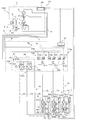
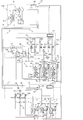
- FIG. 1 is a circuit diagram showing an air-conditioning apparatus 100 according to Embodiment 1 of the present invention.
- the air conditioner 100 will be described with reference to FIG.
- the air conditioner 100 includes an outdoor unit A (heat source unit), a plurality of indoor units X connected in parallel, and a relay unit interposed between the outdoor unit A and the indoor unit X. B, and constitutes a refrigeration cycle.
- Three indoor units X are provided, which are a first indoor unit C, a second indoor unit D, and a third indoor unit E, respectively.
- one outdoor unit A is provided
- one relay unit B is provided
- three indoor units X are provided.
- the outdoor unit A, the relay unit B, and the indoor unit X are provided.
- the number of connected devices is not limited to these numbers.
- two or more outdoor units A may be provided, two or more relay units B may be provided, and two or more indoor units X connected in parallel may be provided.
- the outdoor unit A and the relay unit B are connected by a first connection pipe 6 and a second connection pipe 7.
- the first connection pipe 6 is a liquid side pipe through which the liquid refrigerant flows
- the second connection pipe 7 is a gas side pipe through which the gas refrigerant flows.
- the relay unit B and the indoor unit X are connected by the first indoor unit side connection pipe 6a and the second indoor unit side connection pipe 7a.
- the first indoor unit side connection pipe 6a is a liquid side pipe through which liquid refrigerant flows
- the second indoor unit side connection pipe 7a is a gas side pipe through which gas refrigerant flows.
- the 11th indoor unit side connection pipe 6c and the 21st indoor unit side connection pipe 7c are connected to the first indoor unit C
- the 12th indoor unit is connected to the second indoor unit D.
- the side connection pipe 6d and the twenty-second indoor unit side connection pipe 7d are connected, and the thirteenth indoor unit side connection pipe 6e and the twenty-third indoor unit side connection pipe 7e are connected to the third indoor unit E. Has been.
- a fluorocarbon refrigerant such as R32, R125, R134a of HFC refrigerant, or R410a, R407c, R404A of these mixed refrigerants, etc.
- the refrigerant is HFO refrigerant such as HFO-1234yf, HFO-1234ze (E), HFO-1234ze (Z), etc., CO 2 refrigerant, HC refrigerant (eg propane refrigerant, isobutane refrigerant), ammonia refrigerant, R32 and HFO—
- a mixed refrigerant of the above refrigerant such as a mixed refrigerant of 1234yf may be used.
- the refrigerant used in the vapor compression heat pump may be used as the refrigerant.
- Outdoor unit A The outdoor unit A is usually installed in a space outside a building such as a building, such as a rooftop, and supplies cold or warm heat to the indoor unit X via the relay unit B.
- the installation location of the outdoor unit A is not limited to the outside, but may be an enclosed space such as a machine room provided with a ventilation port, for example, where exhaust heat can be exhausted outside the building by an exhaust duct. If it is, it may be inside the building.
- the outdoor unit A includes a compressor 1 that compresses refrigerant, a flow path switching unit 2 that includes a four-way valve that switches a refrigerant flow direction, an outdoor heat exchanger 3 that performs heat exchange between the fluid and the refrigerant, and liquid refrigerant.
- the accumulator 4 to store and the outdoor control part 50 are provided.
- the compressor 1, the flow path switching unit 2, the outdoor heat exchanger 3, and the accumulator 4 are connected by a first connection pipe 6 and a second connection pipe 7. Further, in the vicinity of the outdoor heat exchanger 3, an outdoor fan 3m is provided as a flow rate control unit that controls the flow rate of the fluid that exchanges heat with the refrigerant.
- the compressor 1 sucks refrigerant and compresses the refrigerant to a high temperature and high pressure state.
- the compressor 1 can be composed of an inverter compressor whose capacity can be controlled.
- the flow path switching unit 2 switches the refrigerant flow direction during the heating operation and the refrigerant flow direction during the cooling operation.
- the outdoor heat exchanger 3 acts as an evaporator during heating operation, and acts as a condenser or a radiator during cooling operation. The outdoor heat exchanger 3 exchanges heat between the fluid (for example, air) supplied from the outdoor fan 3m and the refrigerant, and evaporates or condenses the refrigerant.
- the accumulator 4 is provided on the suction side of the compressor 1, stores excess refrigerant caused by a difference between the refrigerant circulation amount during the heating operation and the refrigerant circulation amount during the cooling operation, and changes in transient operation occur. It stores excess refrigerant.
- a discharge pressure detection unit 31 is provided in the discharge side piping of the compressor 1, and a suction pressure detection unit 32 is provided in the suction side piping of the compressor 1. Further, an outdoor temperature detector 41 is provided in the vicinity of the outdoor heat exchanger 3. And the outdoor control part 50 controls each structure of the air conditioning apparatus 100 based on the pressure information and temperature information which were detected by these discharge pressure detection part 31, the suction pressure detection part 32, and the outdoor temperature detection part 41. .
- the repeater B is installed outside a building or inside a building such as a ceiling or the like, which is a space different from the indoor space, and distributes the cold or hot heat supplied from the outdoor unit A to the indoor unit X. is there.
- the relay machine B may be installed in a common space where an elevator or the like is installed.
- the relay unit B includes a first branch pipe 9b connected to the first connection pipe 6 of the outdoor unit A, that is, the liquid side pipe, and a second connection pipe 7 of the outdoor unit A, that is, the refrigerant branch part.
- a second branch part 9a connected to the gas side pipe and a relay control part 51 are provided.
- the 2nd indoor unit side connection piping 7a, ie, gas side piping, in the some indoor unit X merges.
- the first branching section 9b in the relay station B includes the first refrigerant shut-off valves 21 that control the refrigerant flow in both directions, the number of which is less than the number of the plurality of indoor units X.
- one first refrigerant cutoff valve 21 is provided in the first branch portion 9b.
- the first branching portion 9b includes a path that allows the refrigerant to flow from the indoor unit X to the relay unit B, and a path that allows the refrigerant to flow from the relay unit B to the indoor unit X.
- the one refrigerant shut-off valve 21 is provided on the upstream side of a branch point that branches into a plurality of indoor units X in a path that allows the refrigerant to flow from the relay unit B to the indoor unit X.
- the 1st branch part 9b in the relay machine B is arrange
- the parallel check valve 23b is a generic name, and the first parallel check valve 23f provided in the eleventh indoor unit side connection pipe 6c and the second parallel check provided in the twelfth indoor unit side connection pipe 6d.
- the series check valve 23a is a generic name, and the first series check valve 23c provided in the eleventh indoor unit side connection pipe 6c and the second series valve provided in the twelfth indoor unit side connection pipe 6d. And a third series check valve 23e provided in the thirteenth indoor unit side connection pipe 6e.
- the relay machine B includes a second refrigerant shut-off valve 22 that controls the flow of refrigerant in both directions, and the refrigerant that flows out of the second refrigerant shut-off valve 22 joins at the second branch portion 9a.
- the second refrigerant shut-off valve 22 is a generic name, and the 21st refrigerant shut-off valve 22c provided in the 21st indoor unit side connection pipe 7c and the 22nd indoor unit side connection pipe 7d provided in the 22nd It consists of a refrigerant shut-off valve 22d and a 23rd refrigerant shut-off valve 22e provided in the 23rd indoor unit side connecting pipe 7e.
- the relay control unit 51 controls the opening / closing operation of the first refrigerant cutoff valve 21 and the second refrigerant cutoff valve 22.
- the indoor unit X is installed in a place where the conditioned air can be supplied to the air-conditioning target space such as a room, and the cooling air or the thermal energy distributed from the outdoor unit A via the relay unit B to the air-conditioning target space. Heating air is supplied.
- the indoor unit X includes an indoor heat exchanger 5 that performs heat exchange between the fluid and the refrigerant, an indoor expansion unit 8 that expands by decompressing the refrigerant, and an indoor control unit 52.
- the indoor expansion part 8 and the first branch part 9b are connected by a first indoor unit side connection pipe 6a, and the indoor heat exchanger 5 and the second branch part 9a are connected to the second indoor part. It is connected by the machine side connection piping 7a.
- an indoor blower 5a that is a flow rate control unit that controls the flow rate of the fluid that exchanges heat with the refrigerant.
- the indoor heat exchanger 5 acts as a condenser during heating operation, and acts as an evaporator during cooling operation.
- the indoor heat exchanger 5 performs heat exchange between a fluid supplied from the indoor blower 5a, for example, air and a refrigerant, and condensates or evaporates the refrigerant.
- the indoor heat exchanger 5 is a generic name, and includes a first indoor heat exchanger 5c provided in the first indoor unit C, a second indoor heat exchanger 5d provided in the second indoor unit D, And a third indoor heat exchanger 5e provided in the third indoor unit E.
- the indoor expansion unit 8 is a generic name, and the first indoor expansion unit 8c provided in the first indoor unit C, the second indoor expansion unit 8d provided in the second indoor unit D, 3 indoor expansion part 8e provided in 3 indoor units E.
- the indoor blower 5a is a generic name, the first indoor blower 5cm provided in the first indoor unit C, the second indoor blower 5dm provided in the second indoor unit D, and the third indoor blower. And a third indoor fan 5em provided in the machine E.
- the first indoor unit side connection piping 6a is provided with a first indoor unit temperature detection unit 34
- the second indoor unit side connection piping 7a is provided with a second indoor unit temperature detection unit 33.
- an indoor temperature detector 42 is provided in the vicinity of the indoor heat exchanger 5.
- the indoor control part 52 of the air conditioning apparatus 100 is based on the temperature information detected by these 1st indoor unit temperature detection parts 34, the 2nd indoor unit temperature detection part 33, and the indoor temperature detection part 42. Control each configuration.
- a refrigerant leakage detector 43 that detects refrigerant leakage is provided in the vicinity of the air inlet or outlet of the indoor heat exchanger 5.
- the refrigerant leakage detection unit 43 is, for example, a refrigerant concentration detection unit that detects the refrigerant concentration in the air, and determines that the refrigerant has leaked when the refrigerant concentration in the air exceeds a predetermined threshold value. It is.
- the first indoor unit temperature detection unit 34 is a generic term, and includes an eleventh indoor unit temperature detection unit 34c provided in the eleventh indoor unit side connection pipe 6c and a twelfth indoor unit side connection pipe 6d. It comprises a twelfth indoor unit temperature detector 34d provided and a thirteenth indoor unit temperature detector 34e provided in the thirteenth indoor unit side connecting pipe 6e.
- the second indoor unit temperature detection unit 33 is a generic name, and includes a twenty-first indoor unit temperature detection unit 33c provided in the twenty-first indoor unit side connection pipe 7c and a twenty-second indoor unit side connection pipe 7d. It comprises a 22nd indoor unit temperature detector 33d provided and a 23rd indoor unit temperature detector 33e provided in the 23rd indoor unit side connection pipe 7e.
- the indoor temperature detector 42 is a generic name, and the first indoor temperature detector 42c provided in the vicinity of the first indoor heat exchanger 5c and the second indoor heat detector 5d provided in the vicinity of the second indoor heat exchanger 5d. Indoor temperature detector 42d and a third indoor temperature detector 42e provided in the vicinity of the third indoor heat exchanger 5e.
- the indoor control unit 52 is a generic name, and the first indoor control unit 52c provided in the first indoor unit C, the second indoor control unit 52d provided in the second indoor unit D, And a third indoor control unit 52e provided in the third indoor unit E.
- the refrigerant leak detection unit 43 is a generic name, and is provided in the vicinity of the first refrigerant leak detection unit 43c provided in the vicinity of the first indoor heat exchanger 5c and the second indoor heat exchanger 5d. It consists of a second refrigerant leak detection unit 43d and a third refrigerant leak detection unit 43e provided in the vicinity of the third indoor heat exchanger 5e.
- the control unit 70 includes an outdoor control unit 50, a relay control unit 51, and an indoor control unit 52.
- the control unit 70 causes the outdoor heat exchanger 3 to be a flow path that acts as a condenser.
- the path switching unit 2 is controlled.
- the operation mode in the air conditioning apparatus 100 is equipped with two modes of cooling operation and heating operation.
- the cooling operation only the cooling operation is performed for the indoor unit X, and the indoor unit X is cooled or stopped.
- the heating operation only the heating operation is performed for the indoor unit X, and the indoor unit X is heated or stopped. Operations in these cooling operation and heating operation will be described with reference to a Ph diagram.
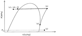
- FIG. 2 is a circuit diagram showing the cooling operation in the first embodiment of the present invention
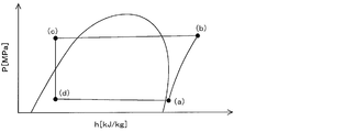
- FIG. 3 is a Ph diagram of the cooling operation in the first embodiment of the present invention.
- the compressor 1 sucks and compresses the low-temperature and low-pressure gas refrigerant and discharges the high-temperature and high-pressure gas refrigerant.
- the compressor 1 is compressed so as to be heated by the amount of heat insulation efficiency of the compressor 1 rather than being adiabatically compressed by an isentropic line (point (a) in FIG. 3). To the point (b).
- the high-temperature and high-pressure gas refrigerant discharged from the compressor 1 flows into the outdoor heat exchanger 3 via the flow path switching unit 2. At this time, the refrigerant is cooled while heating the outdoor air blown from the outdoor blower 3m, and becomes a medium-temperature high-pressure liquid refrigerant.
- the state change of the refrigerant in the outdoor heat exchanger 3 takes a line segment slightly inclined from the horizontal direction from the point (b) to the point (c) in FIG. 3 in consideration of the pressure loss of the outdoor heat exchanger 3.
- the medium-temperature and high-pressure liquid refrigerant that has flowed out of the outdoor heat exchanger 3 is connected to the first connection pipe 6, the first refrigerant shut-off valve 21 and the series check valve 23a in the first branch portion 9b, and the first indoor unit side connection. It distribute
- the medium temperature and high pressure liquid refrigerant is squeezed and expanded and depressurized in the indoor expansion section 8 to become a low temperature and low pressure gas-liquid two-phase refrigerant.
- coolant in the indoor expansion part 8 is performed in the state where enthalpy is constant.
- the state change of the refrigerant in the indoor expansion portion 8 is a vertical line from the point (c) to the point (d) in FIG.
- the refrigerant state change in the indoor heat exchanger 5 becomes a line segment slightly inclined from the horizontal direction from the point (d) to the point (a) in FIG.
- the low-temperature and low-pressure gas refrigerant that has flowed out of the indoor heat exchanger 5 passes through the second indoor unit side connection pipe 7a and the second refrigerant shut-off valve 22, and reaches the second branch portion 9a.
- the low-temperature and low-pressure gas refrigerant merged at the second branch part 9a flows into the compressor 1 through the second connection pipe 7 and the flow path switching part 2, and is compressed.
- FIG. 4 is a circuit diagram showing the heating operation in the first embodiment of the present invention
- FIG. 5 is a Ph diagram of the heating operation in the first embodiment of the present invention.
- the compressor 1 sucks and compresses the low-temperature and low-pressure gas refrigerant and discharges the high-temperature and high-pressure gas refrigerant.
- the compressor 1 is compressed so as to be heated by the amount of the heat insulation efficiency of the compressor 1 rather than being adiabatically compressed by an isentropic line (point (a) in FIG. 5). To the point (b).
- the high-temperature and high-pressure gas refrigerant discharged from the compressor 1 flows into the second branch part 9a via the flow path switching part 2 and the second connection pipe 7.
- the high-temperature and high-pressure gas refrigerant that has flowed into the second branch portion 9a branches at the second branch portion 9a, passes through the second refrigerant shut-off valve 22, and the second indoor unit side connection pipe 7a, It flows into the indoor heat exchanger 5.
- the refrigerant is cooled while heating the indoor air blown from the indoor blower 5a, and becomes a medium-temperature high-pressure liquid refrigerant.
- the state change of the refrigerant in the indoor heat exchanger 5 takes a line segment slightly inclined from the horizontal direction from the point (b) to the point (c) in FIG. 5 in consideration of the pressure loss of the indoor heat exchanger 5.
- coolant in the indoor expansion part 8 is performed in the state where enthalpy is constant.
- the state change of the refrigerant in the indoor expansion portion 8 is a vertical line from the point (c) to the point (d) in FIG.
- the low-temperature and low-pressure gas-liquid two-phase refrigerant that has flowed out of the indoor expansion section 8 passes through the first indoor unit side connection pipe 6a, the parallel check valve 23b in the first branch section 9b, and the first connection pipe 6. It flows into the outdoor heat exchanger 3. At this time, the refrigerant is heated while cooling the outdoor air blown from the outdoor blower 3m, and becomes a low-temperature and low-pressure gas refrigerant.
- the state change of the refrigerant in the outdoor heat exchanger 3 becomes a line segment slightly inclined from the horizontal direction from the point (d) to the point (a) in FIG.
- the low-temperature and low-pressure gas refrigerant flowing out of the outdoor heat exchanger 3 flows into the compressor 1 through the flow path switching unit 2 and is compressed.
- the refrigerant recovery operation for reducing the refrigerant leakage amount to the room as much as possible when the refrigerant leaks will be described.
- the refrigerant leakage detection unit 43 detects that the refrigerant has leaked from the first indoor unit C, for example, the refrigerant leakage detection unit 43 detects the refrigerant concentration in the air.
- the flow path switching unit 2 is controlled so that the outdoor heat exchanger 3 becomes a flow path that acts as a condenser.
- FIG. 6 is a circuit diagram showing the refrigerant recovery operation in the first embodiment of the present invention
- FIG. 7 is a Ph diagram of the refrigerant recovery operation in the first embodiment of the present invention.
- the compressor 1 sucks and compresses the low-temperature and low-pressure gas refrigerant, and discharges the high-temperature and high-pressure gas refrigerant.
- the compressor 1 is compressed so as to be heated by the amount of heat insulation efficiency of the compressor 1 rather than being adiabatically compressed by an isentropic line (point (a) in FIG. 7). To the point (b).
- the high-temperature and high-pressure gas refrigerant discharged from the compressor 1 flows into the outdoor heat exchanger 3 via the flow path switching unit 2. At this time, while the refrigerant heats outdoor air blown from the outdoor blower 3m, it is cooled and becomes a medium-temperature high-pressure liquid refrigerant.
- the state change of the refrigerant in the outdoor heat exchanger 3 takes a line segment slightly inclined from the horizontal direction from the point (b) to the point (c) in FIG. 7 in consideration of the pressure loss of the outdoor heat exchanger 3.
- the outdoor heat exchanger 3 acts as a condenser
- the refrigerant flowing out of the outdoor heat exchanger 3 becomes a liquid refrigerant, and this liquid refrigerant is more likely to stay inside the pipe than a gas refrigerant. Therefore, the refrigerant flowing through the refrigeration cycle is recovered as much as possible.
- the refrigerant circulating in the second indoor unit D, the third indoor unit E, etc. does not flow into the first indoor unit C, Leakage is prevented.
- the refrigerant pressure in the second indoor heat exchanger 5d and the third indoor heat exchanger 5e is the same as that of the compressor 1 because the 22nd refrigerant shutoff valve 22d and the 23rd refrigerant shutoff valve 22e are open. This is equivalent to the pressure on the suction side (point (d) in FIG. 7).
- the refrigerant pressure in the first indoor unit C eventually decreases to the atmospheric pressure PA because the refrigerant leaks into the room (point (e) in FIG. 7).
- the relay control unit 51 of the relay unit B causes the indoor unit X in which the refrigerant has leaked.
- the second refrigerant cutoff valve 22 and the first refrigerant cutoff valve 21 connected to are opened and closed.
- the second refrigerant shut-off valve 22 is open during normal operation and closed when the refrigerant leaks. This prevents the refrigerant from flowing into the second indoor unit side connection pipe 7a.
- the first refrigerant shut-off valve 21 is open during normal operation and is closed when the refrigerant leaks.
- the series check valve 23a (the first series check valve 23c, the second series check valve 23d, and the third series check valve 23e) prevents the refrigerant from flowing between the indoor units X. is there.
- the refrigerant leaks in any of the indoor units X and the first refrigerant shut-off valve 21 is shut off, the refrigerant on the other indoor unit X side where the refrigerant is not leaking is changed by the series check valve 23a. Distribution to the leaked indoor unit X side can be prevented.
- the air-conditioning apparatus 100 includes the first refrigerant shut-off valves 21 in the first branch portion 9b, which is less than the number of indoor units X. Both cost reduction and control simplification can be achieved.
- the first refrigerant shut-off valve 21 is provided in the first branch portion 9b where the first indoor unit side connection pipe 6a of the indoor unit X joins, and the second indoor unit side connection pipe 7a of the indoor unit X is provided. It is provided for each. For this reason, in the case where any refrigerant leaks indoors in any of the indoor units X, the second refrigerant shut-off valve 22 provided in the second indoor unit side connection pipe 7a of the leaking indoor unit X. , And closing the first refrigerant shut-off valve 21 provided at the portion where the first indoor unit side connecting pipe 6a joins in the first branch portion 9b, to reduce the leakage of the refrigerant to the room as much as possible. Can do.
- the control part 70 becomes the flow path where the outdoor heat exchanger 3 acts as a condenser.
- the flow path switching unit 2 is controlled. For this reason, the refrigerant flowing out of the outdoor heat exchanger 3 becomes a liquid refrigerant, and this liquid refrigerant is more likely to stay inside the pipe than the gas refrigerant. Accordingly, it is possible to increase the recovery amount of the refrigerant flowing through the refrigeration cycle.
- FIG. 8A is a circuit diagram showing an air-conditioning apparatus 101a according to Embodiment 2 of the present invention.
- the second embodiment is different from the first embodiment in that the number of installed second refrigerant cutoff valves 22 is less than the number of indoor units X in the relay unit B.
- portions common to the first embodiment are denoted by the same reference numerals, description thereof is omitted, and differences from the first embodiment will be mainly described.
- the repeater B includes an indoor relay check valve 24a and a relay indoor check valve 24b.
- the indoor relay check valve 24a is connected from the indoor unit X to the second branch unit 9a where each second indoor unit side connection pipe 7a in the plurality of indoor units X, that is, each gas side pipe in the cooling operation joins.
- the refrigerant flow toward B is allowed.
- the relay indoor check valve 24b is connected in parallel to the indoor relay check valve 24a, and in the second branch portion 9a branched to each gas side pipe in the heating operation, the relay unit B is connected to the indoor unit X.
- the flow of the refrigerant toward is allowed.
- the second refrigerant shut-off valve 22 is provided on the upstream side of the pipe branched to the relay chamber check valve 24b. That is, the second branching portion 9a is configured by a path that allows the refrigerant to flow from the indoor unit X to the relay unit B, and a path that allows the refrigerant to flow from the relay unit B to the indoor unit X.
- the second refrigerant shut-off valve 22 is provided on the upstream side of a branch point that branches into the plurality of indoor units X in a path that allows the refrigerant to flow from the relay unit B to the indoor unit X.
- the indoor relay check valve 24a is a generic name, and is provided in the first indoor relay check valve 24c provided in the 21st indoor unit side connection pipe 7c and the 22nd indoor unit side connection pipe 7d.
- the second indoor relay check valve 24d and the third indoor relay check valve 24e provided in the 23rd indoor unit side connection pipe 7e.
- the relay indoor check valve 24b is a generic term, and is provided in the first relay indoor check valve 24f provided in the 21st indoor unit side connection pipe 7c and the 22nd indoor unit side connection pipe 7d. It consists of a second relay indoor check valve 24g and a third relay indoor check valve 24h provided in the 23rd indoor unit side connection pipe 7e.
- the relay chamber check valve 24b distributes the refrigerant between the indoor units X. Is to prevent.
- the refrigerant leaks in any of the indoor units X and the second refrigerant shut-off valve 22 is shut off, the refrigerant in the other indoor unit X side where the refrigerant is not leaked by the relay indoor check valve 24b becomes the refrigerant. Can be prevented from circulating to the leaked indoor unit X side.
- the control unit 70 has a function of closing the first refrigerant cutoff valve 21 and the second refrigerant cutoff valve 22 when the refrigerant leakage detection unit 43 detects that the refrigerant has leaked in at least one of the plurality of indoor units X. It has.
- the air-conditioning apparatus 101a includes the second refrigerant shut-off valves 22 in the second branch portion 9a, which is less than the number of indoor units X. For this reason, cost reduction and control simplification can be compatible.
- coolant cutoff valve 21 is provided in the 1st branch part 9b where the 1st indoor unit side connection piping 6a of the indoor unit X merges, and the 2nd refrigerant
- the second indoor unit side connection pipe 7a is provided at the second branch portion 9a where the second indoor unit side connection pipe 7a joins.
- any one of the indoor units X when the refrigerant leaks into the room, the second refrigerant provided in the portion where the second indoor unit side connection pipe 7a merges in the second branch portion 9a.
- the first refrigerant shut-off valve 21 provided at the portion where the shut-off valve 22 and the first indoor unit side connecting pipe 6a in the first branch portion 9b merge leakage of the refrigerant into the room, It can be reduced as much as possible.
- the control part 70 becomes the flow path where the outdoor heat exchanger 3 acts as a condenser.
- the flow path switching unit 2 is controlled. For this reason, the refrigerant flowing out of the outdoor heat exchanger 3 becomes a liquid refrigerant, and this liquid refrigerant is more likely to stay inside the pipe than the gas refrigerant. Accordingly, it is possible to increase the recovery amount of the refrigerant flowing through the refrigeration cycle.
- FIG. 8B is a circuit diagram showing an air conditioner 101 according to a modification of the second embodiment of the present invention.
- the modification of the second embodiment is implemented in that the relay machine B includes the indoor relay flow path control valve 10a and the relay indoor flow path control valve 10b, and does not include the second refrigerant cutoff valve 22.
- the relay machine B includes the indoor relay flow path control valve 10a and the relay indoor flow path control valve 10b, and does not include the second refrigerant cutoff valve 22.
- portions common to the first and second embodiments are denoted by the same reference numerals and description thereof will be omitted, and differences from the first and second embodiments will be mainly described.
- the relay unit B includes an indoor relay flow path control valve 10a, a relay indoor flow path control valve 10b, an indoor relay check valve 24a, and a relay indoor check valve 24b.
- the indoor relay flow path control valve 10a relays from the indoor unit X at each second indoor unit side connection pipe 7a in the plurality of indoor units X, that is, in the second branch portion 9a where the gas side pipes in the cooling operation join.
- the flow of the refrigerant in one direction toward the machine B is controlled.
- the relay indoor flow path control valve 10b controls the refrigerant flow in one direction from the relay machine B to the indoor unit X at the second branching portion 9a, and is connected in parallel to the indoor relay flow path control valve 10a. It is what is done.
- the indoor relay flow path control valve 10a and the relay indoor flow path control valve 10b are, for example, electromagnetic valves.
- the indoor relay flow path control valve 10a is closer to the second branch portion 9a side (the tip end side of the arrow in FIG. 8B) than to the indoor unit X side (the base end side of the arrow in FIG. 8B).
- the opening / closing operation is normally performed.
- the relay indoor flow path control valve 10b is closer to the second branch portion 9a side (the base end side of the arrow in FIG. 8B) than to the indoor unit X side (the tip end side of the arrow in FIG. 8B).
- the opening / closing operation is normally performed.
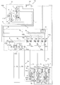
- FIG. 8C is a diagram showing a structure of the indoor relay flow path control valve 10a in the modification of the second embodiment of the present invention.
- the indoor relay flow path control valve 10a is, for example, a pilot-type electromagnetic valve.
- the indoor relay flow path control valve 10a (pilot solenoid valve) is a valve having a relatively large Cv value, and the flow path is blocked by the plunger 80 and the main valve 81.
- the plunger 80 and the main valve 81 are independent of each other.
- a low-pressure atmosphere refrigerant is sealed in the plunger 80.
- the plunger 80 is operated by the suction force of the solenoid coil 82, and the main valve 81 is operated by the fluid pressure.
- the large-diameter main valve 81 can be operated with a simple structure and a small amount of power.
- the cost can be reduced as compared with the case where the valve that blocks the bidirectional flow is used.
- the relay indoor flow path control valve 10b may also have the same structure as the indoor relay flow path control valve 10a.
- the indoor relay flow path control valve 10a is a generic term, and is provided in the first indoor relay flow path control valve 10c provided in the 21st indoor unit side connection pipe 7c and the 22nd indoor unit side connection pipe 7d.
- the second indoor relay flow path control valve 10d and the third indoor relay flow path control valve 10e provided in the 23rd indoor unit side connection pipe 7e.
- the relay indoor flow path control valve 10b is a generic term, and is provided in the first relay indoor flow path control valve 10f provided in the 21st indoor unit side connection pipe 7c and the 22nd indoor unit side connection pipe 7d.
- the second relay indoor flow path control valve 10g and the third relay indoor flow path control valve 10h provided in the 23rd indoor unit side connection pipe 7e.
- the indoor relay check valve 24a is connected in series to the indoor relay flow path control valve 10a, and is provided on the upstream side of the indoor relay flow path control valve 10a.
- the indoor relay check valve 24a may be provided on the downstream side of the indoor relay flow path control valve 10a.
- the relay chamber check valve 24b is connected in series to the relay chamber flow control valve 10b, and is provided on the upstream side of the relay chamber flow control valve 10b.
- the relay chamber check valve 24b may be provided on the downstream side of the relay chamber flow control valve 10b.
- the indoor relay check valve 24a is connected in series to the indoor relay flow path control valve 10a, and the relay indoor check valve 24b is connected in series to the relay indoor flow path control valve 10b.
- the indoor relay flow path control valve 10a and the relay indoor flow path control valve 10b are normally opened and closed.
- the indoor relay flow path control valve 10a can be omitted, and only the indoor relay check valve 24a may be provided.
- the indoor relay check valve 24a is a generic name, and the first indoor relay check valve 24c provided in the 21st indoor unit side connection pipe 7c and the second indoor relay check valve 24d provided in the 22nd indoor unit side connection pipe 7d.
- the relay indoor check valve 24b is a generic name, and the first relay indoor check valve 24f provided in the 21st indoor unit side connection pipe 7c and the second provided in the 22nd indoor unit side connection pipe 7d.
- Relay indoor check valve 24g and a third relay indoor check valve 24h provided in the 23rd indoor unit side connection pipe 7e.
- the control unit 70 controls the indoor relay flow path connected to the indoor unit X in which the refrigerant is leaking.
- the valve 10a is opened, the relay indoor flow path control valve 10b connected to the indoor unit X where the refrigerant is leaking is closed, and the first refrigerant shut-off valve 21 is closed.
- the indoor relay flow path control valve 10a When the cooling operation is performed in the indoor unit X, the indoor relay flow path control valve 10a is opened and the relay indoor flow path control valve 10b is closed. Moreover, when heating operation is performed in the indoor unit X, the relay indoor flow path control valve 10b is opened, and the indoor relay flow path control valve 10a is closed.
- the control unit 70 sets the flow path so that the outdoor heat exchanger 3 functions as a flow path.
- the switching unit 2 is controlled.
- the control part 70 opens the indoor relay flow path control valve 10a connected to the indoor unit X in which the refrigerant is leaking, and the relay indoor flow path control valve 10b connected to the indoor unit X in which the refrigerant is leaking.
- the first refrigerant shutoff valve 21 is closed.
- the operation of the air conditioner 101 according to the modification of the second embodiment will be described. Since the relay indoor flow path control valve 10b connected to the indoor unit X in which the refrigerant is leaking is closed, the indoor unit X in which the pressure drops to approach atmospheric pressure due to the leakage of the refrigerant is The refrigerant does not circulate.
- the control unit 70 becomes a flow path in which the outdoor heat exchanger 3 acts as a condenser.
- the flow path switching unit 2 is controlled.
- the controller 70 increases the speed of the compressor 1 and decreases the suction pressure of the compressor 1 (point (a) in FIG. 7).
- the air conditioner 101 reduces the suction pressure of the compressor 1 below the pressure of the indoor unit X where the refrigerant has leaked, so that the refrigerant leaks through the indoor relay check valve 24a. It becomes easy to collect the refrigerant from all the indoor units X including the generated indoor unit X. Therefore, the leakage amount of the refrigerant leaking into the room can be reduced as much as possible.
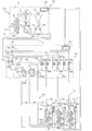
- FIG. 9 is a circuit diagram showing an air-conditioning apparatus 102 according to Embodiment 3 of the present invention.
- the second branch portion 9a includes a third branch portion 9c connected to the discharge side of the compressor 1 and a fourth branch portion 9d connected to the suction side of the compressor 1. This is different from the second embodiment.
- portions common to the first and second embodiments are denoted by the same reference numerals and the description thereof is omitted, and the difference from the first and second embodiments will be mainly described.
- one end of the third connection pipe 11 is connected to the discharge side of the compressor 1, and the other end of the third connection pipe 11 is connected to the second branch portion 9 a.
- a third branch 9c is connected. From the third branch portion 9c, the refrigerant branches to the relay chamber flow control valve 10b.
- the relay chamber check valve 24b in the second embodiment is omitted.
- FIG. 1 The fourth branch portion 9d is where the refrigerant merges from the indoor relay flow path control valve 10a.
- the outdoor unit A includes an outdoor expansion unit 20 and is provided on the outdoor heat exchanger 3 side in the first connection pipe 6.
- the indoor unit X By opening / closing the indoor relay flow path control valve 10a and the relay indoor flow path control valve 10b provided in the relay machine B, the indoor unit X is connected to the discharge side of the compressor 1 or to the suction side of the compressor 1 The connection is switched. Thereby, the indoor unit X performs a cooling operation or a heating operation.
- the pressure in each branch portion is the pressure of the third branch portion 9c> the pressure of the first branch portion 9b> the pressure of the fourth branch portion 9d. Therefore, the indoor relay flow path control valve 10a and the relay indoor flow path control valve 10b operate normally.
- the indoor relay check valve 24a is connected in series, so that the refrigerant leaks in the indoor unit X, and the indoor unit X side Even if the pressure of the refrigerant decreases, the refrigerant circulating other than the indoor unit X where the refrigerant leaks does not flow into the indoor unit X where the refrigerant leaks.
- the air-conditioning apparatus 102 according to Embodiment 3 selects cooling or heating for each indoor unit X, and performs cooling and heating simultaneous operation in which the indoor unit X in which cooling is performed and the indoor unit X in which heating operation is performed simultaneously exist. Is possible.
- the operation mode in the air conditioning apparatus 102 which concerns on this Embodiment 3 is mounted with four modes, cooling operation, heating operation, cooling main operation, and heating main operation. That is, in addition to the cooling operation and the heating operation in the air-conditioning apparatus 100 according to Embodiment 1 and the air-conditioning apparatus 101 according to Embodiment 2, two operation modes are further mounted.
- the cooling load is larger than the heating load
- the outdoor heat exchanger 3 is connected to the discharge side of the compressor 1 and acts as a condenser.
- the heating load is larger than the cooling load in the simultaneous cooling and heating operation
- the outdoor heat exchanger 3 is connected to the suction side of the compressor 1 and functions as an evaporator.
- the refrigerant flows in a state where the indoor relay flow path control valve 10a is opened and the relay indoor flow path control valve 10b is closed.
- the refrigerant flows in a state where the indoor relay flow path control valve 10a is closed and the relay indoor flow path control valve 10b is opened. Since these cooling operation and heating operation are the same as in the first and second embodiments, description thereof will be omitted. Hereinafter, operations in the cooling main operation and the heating main operation will be described with reference to a Ph diagram.
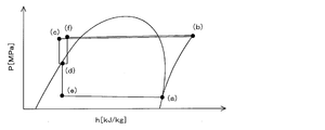
- FIG. 10 is a circuit diagram showing a cooling main operation in the third embodiment of the present invention
- FIG. 11 is a Ph diagram of the cooling main operation in the third embodiment of the present invention.
- the compressor 1 sucks and compresses the low-temperature and low-pressure gas refrigerant and discharges the high-temperature and high-pressure gas refrigerant.
- the compressor 1 is compressed so as to be heated by the amount of heat insulation efficiency of the compressor 1 rather than being adiabatically compressed by an isentropic line (point (a) in FIG. 11). To the point (b).
- the high-temperature and high-pressure gas refrigerant discharged from the compressor 1 branches into a refrigerant that goes to the flow path switching unit 2 and a refrigerant that goes to the third connection pipe 11.
- the refrigerant toward the flow path switching unit 2 flows into the outdoor heat exchanger 3 via the flow path switching unit 2.
- the refrigerant heats outdoor air blown from the outdoor blower 3m, it is cooled and becomes a medium-temperature high-pressure liquid refrigerant.
- the state change of the refrigerant in the outdoor heat exchanger 3 takes a line segment slightly inclined from the horizontal direction from the point (b) to the point (c) in FIG. 11 in consideration of the pressure loss of the outdoor heat exchanger 3.
- the medium-temperature and high-pressure liquid refrigerant that has flowed out of the outdoor heat exchanger 3 is squeezed and expanded and depressurized in the outdoor expansion section 20 to become a low-temperature and low-pressure gas-liquid two-phase refrigerant.
- coolant in the outdoor expansion part 20 is performed in the state where enthalpy is constant.
- the state change of the refrigerant in the outdoor expansion portion 20 is as a vertical line from the point (c) to the point (d) in FIG. Thereafter, the refrigerant flows into the first branch portion 9 b through the first connection pipe 6.
- the refrigerant circulated from the compressor 1 to the third connection pipe 11 then flows into the third branch portion 9c, passes through the third relay indoor flow path control valve 10h, and passes through the second indoor unit side. It flows into the connecting pipe 7a. And it flows in into the 3rd indoor heat exchanger 5e. At this time, while the refrigerant is heating the indoor air blown from the third indoor blower 5em, it is cooled and becomes a medium-temperature high-pressure liquid refrigerant.
- the state change of the refrigerant in the indoor heat exchanger 5 takes a line segment slightly inclined from the horizontal direction from the point (b) to the point (f) in FIG. 11 in consideration of the pressure loss of the indoor heat exchanger 5.
- coolant in the indoor expansion part 8 is performed in the state where enthalpy is constant.
- the state change of the refrigerant in the indoor expansion portion 8 is as shown by a vertical line from the point (f) to the point (d) in FIG. Note that point (c) and point (f) in FIG.
- the refrigerant flows into the first branch portion 9b through the thirteenth indoor unit side connecting pipe 6e. At this time, the refrigerant merges with the refrigerant that flows out of the outdoor expansion portion 20 and circulates in the first connection pipe 6.
- the refrigerant that has merged in the first branch portion 9b passes through the first refrigerant shut-off valve 21, and then divides into the first series check valve 23c and the second series check valve 23d to circulate.
- the refrigerant that has passed through the first series check valve 23c and the second series check valve 23d passes through the eleventh indoor unit side connection pipe 6c and the twelfth indoor unit side connection pipe 6d, respectively. Flows into the indoor expansion portion 8c and the second indoor expansion portion 8d.
- the medium-temperature and high-pressure liquid refrigerant is squeezed and expanded and decompressed in the first indoor expansion section 8c and the second indoor expansion section 8d to become a low-temperature and low-pressure gas-liquid two-phase refrigerant.
- coolant in the 1st indoor expansion part 8c and the 2nd indoor expansion part 8d is performed in a state with a fixed enthalpy.
- the state change of the refrigerant in the first indoor expansion portion 8c and the second indoor expansion portion 8d is like a vertical line from the point (d) to the point (e) in FIG.
- the refrigerant state change in the first indoor heat exchanger 5c and the second indoor heat exchanger 5d is shown in FIG. 11 in consideration of the pressure loss of the first indoor heat exchanger 5c and the second indoor heat exchanger 5d.
- the line segment is slightly inclined from the horizontal direction from the point (e) to the point (a).
- the low-temperature and low-pressure gas refrigerants flowing out from the first indoor heat exchanger 5c and the second indoor heat exchanger 5d are respectively connected to the 21st indoor unit side connecting pipe 7c and the 22nd indoor unit side connecting pipe 7d, respectively.
- the low-temperature and low-pressure gas refrigerant merged at the fourth branch portion 9d flows into the compressor 1 through the second connection pipe 7 and the flow path switching portion 2, and is compressed.
- FIG. 12 is a circuit diagram showing a heating main operation in the third embodiment of the present invention
- FIG. 13 is a Ph diagram of the heating main operation in the third embodiment of the present invention.
- the first indoor relay flow path control valve 10c is opened, and the second indoor relay flow path control valve 10d and the third indoor relay flow path control valve 10e are closed.
- the first relay chamber flow control valve 10f is closed, and the second relay chamber flow control valve 10g and the third relay chamber flow control valve 10h are opened.
- the flow path switching unit 2 is switched so that the refrigerant discharged from the compressor 1 flows into the outdoor heat exchanger 3.
- the outdoor heat exchanger 3 is connected in parallel with the indoor heat exchanger 5 that performs cooling, whereas in the cooling main operation, the outdoor heat exchanger 3 performs heating with the indoor heat exchanger 5 that performs heating. It differs from the cooling main operation in that it is connected in parallel. That is, in the heating main operation, the refrigerant in the first connection pipe 6 flows from the relay unit B to the outdoor unit A, as shown in FIG. 13, contrary to the cooling main operation.
- the refrigerant changes in the order of point (a).
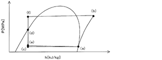
- FIG. 14 is a circuit diagram showing the refrigerant recovery operation in the third embodiment of the present invention
- FIG. 15 is a Ph diagram of the refrigerant recovery operation in the third embodiment of the present invention.
- the flow path switching unit 2 is controlled so that the outdoor heat exchanger 3 becomes a flow path that acts as a condenser. This is because when the operation mode when refrigerant leakage is detected is the cooling operation or the cooling main operation, the flow path remains as it is, and when the operation mode is the heating operation or the heating main operation, the flow path is in the reverse direction.
- control unit 70 opens the first indoor relay flow path control valve 10c, closes the first relay indoor flow path control valve 10f, and closes the first refrigerant cutoff valve 21.
- the second indoor relay flow path control valve 10d, the third indoor relay flow path control valve 10e, the second relay indoor flow path control valve 10g, and the third relay indoor flow path control valve 10h Alternatively, in the heating operation, the open / close state may be set, but when storing the refrigerant in the refrigeration cycle, as shown in FIGS. Since the pressure rises and the refrigerant density increases, more refrigerant can be stored.
- the compressor 1 sucks and compresses a low-temperature and low-pressure gas refrigerant and discharges a high-temperature and high-pressure gas refrigerant when driving is started.
- the compressor 1 is compressed so as to be heated by the amount of heat insulation efficiency of the compressor 1 rather than being adiabatically compressed by an isentropic line (point (a) in FIG. 15). To the point (b).
- the high-temperature and high-pressure gas refrigerant discharged from the compressor 1 flows into the outdoor heat exchanger 3 via the flow path switching unit 2. At this time, while the refrigerant heats outdoor air blown from the outdoor blower 3m, it is cooled and becomes a medium-temperature high-pressure liquid refrigerant.
- the state change of the refrigerant in the outdoor heat exchanger 3 takes a line segment slightly inclined from the horizontal direction from the point (b) to the point (c) in FIG. 15 in consideration of the pressure loss of the outdoor heat exchanger 3.
- the outdoor heat exchanger 3 acts as a condenser
- the refrigerant flowing out of the outdoor heat exchanger 3 becomes a liquid refrigerant, and this liquid refrigerant is more likely to stay inside the pipe than a gas refrigerant. Therefore, the refrigerant flowing through the refrigeration cycle is recovered as much as possible.
- the refrigerant circulating in the second indoor unit D, the third indoor unit E, etc. does not flow into the first indoor unit C. , Refrigerant leakage is prevented.
- the refrigerant pressure in the second indoor heat exchanger 5d and the third indoor heat exchanger 5e is such that the second relay indoor flow path control valve 10g and the third relay indoor flow path control valve 10h are open. Therefore, it is equivalent to the pressure on the discharge side of the compressor 1 (point (d) in FIG. 15).
- the pressure of the refrigerant in the first indoor unit C eventually decreases to the atmospheric pressure PA (point (e) in FIG. 15).
- the air-conditioning apparatus 102 includes the first refrigerant shut-off valves 21 in the first branch portion 9b as many as less than the number of indoor units X. Both cost reduction and control simplification can be achieved.
- the first refrigerant shut-off valve 21 is provided in the first branch portion 9b where the first indoor unit side connection pipe 6a of the indoor unit X joins, and the indoor relay flow path control valve 10a and the relay indoor flow A path control valve 10b is provided for each second indoor unit side connection pipe 7a of the indoor unit X.
- any one of the indoor units X when the refrigerant leaks into the room, the relay indoor flow path control valve 10b provided in the second indoor unit side connection pipe 7a of the leaking indoor unit X. , And closing the first refrigerant shut-off valve 21 provided at the portion where the first indoor unit side connecting pipe 6a joins in the first branch portion 9b, to reduce the leakage of the refrigerant to the room as much as possible. Can do.
- the control part 70 becomes the flow path where the outdoor heat exchanger 3 acts as a condenser.
- the flow path switching unit 2 is controlled. For this reason, the refrigerant flowing out of the outdoor heat exchanger 3 becomes a liquid refrigerant, and this liquid refrigerant is more likely to stay inside the pipe than the gas refrigerant. Accordingly, it is possible to increase the recovery amount of the refrigerant flowing through the refrigeration cycle.
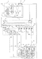
- FIG. 16 is a circuit diagram showing an air conditioner 103 according to Embodiment 4 of the present invention.
- the first connection pipe 6 is a high-pressure pipe where the refrigerant always flows from the outdoor unit A to the relay unit B
- the second connection pipe 7 is the refrigerant always flows from the relay unit B to the outdoor unit A.
- the second embodiment is different from the second embodiment in that low-pressure piping is used.
- portions common to the first, second, and third embodiments are denoted by the same reference numerals, and the description thereof is omitted. The difference from the first, second, and third embodiments will be mainly described.
- the first connection pipe 6 is provided with a first check valve 14 that allows the refrigerant to flow from the outdoor unit A to the relay unit B, and for the second connection.
- the pipe 7 is provided with a second check valve 15 that allows the refrigerant to flow from the relay unit B to the outdoor unit A.
- the pipe connecting the downstream side of the first check valve 14 in the first connection pipe 6 and the downstream side of the second check valve 15 in the second connection pipe 7 includes a second connection pipe.
- a third check valve 16 that allows the refrigerant to flow from 7 to the first connection pipe 6 is provided.
- the pipe connecting the upstream side of the first check valve 14 in the first connection pipe 6 and the upstream side of the second check valve 15 in the second connection pipe 7 has a second connection.
- a fourth check valve 17 that allows the refrigerant to flow from the pipe 7 to the first connection pipe 6 is provided.
- the first connection pipe 6 becomes a high-pressure pipe where the refrigerant always flows from the outdoor unit A to the relay unit B
- the second connection pipe 7 becomes a low-pressure pipe where the refrigerant always flows from the relay unit B to the outdoor unit A.
- the first branch portion 9b is connected to both the first connection pipe 6 and the second connection pipe 7. Between the first branch part 9b and the first connection pipe 6, a first expansion part 12 is provided, and between the first branch part 9b and the second connection pipe 7, A second inflating part 13 is provided.
- the third branch portion 9 c is connected to the first connection pipe 6. Regardless of the operation mode, the first check valve 14, the second check valve 15, the third check valve 16, and the fourth check valve 17 allow the third branch portion 9c to have a discharge pressure.
- the second high pressure side is close to the high pressure side, and the second branch portion 9a is on the low pressure side close to the suction pressure.
- first expansion section 12 and the second expansion section 13 are intermediate pressure liquid in the first branch section 9b, low pressure gas or gas-liquid two phase in the second branch section 9a, and in the third branch section 9c. Controls the pressure of the refrigerant in the high-pressure gas or gas-liquid two-phase.
- the outdoor heat exchanger 3 In the simultaneous cooling and heating operation, the outdoor heat exchanger 3 is connected to the upstream side of the indoor heat exchanger 5 that performs heating during the cooling-main operation, and the outdoor heat exchanger 3 performs the cooling during the heating-main operation. It is connected to the downstream side.
- the air conditioner 103 according to the fourth embodiment in which the first connection pipe 6 and the second connection pipe 7 are connected by two pipes and the cooling and heating simultaneous operation is possible, the refrigerant recovery operation when the refrigerant leaks Will be described.
- FIG. 17 is a circuit diagram showing the refrigerant recovery operation in the fourth embodiment of the present invention
- FIG. 18 is a Ph diagram of the refrigerant recovery operation in the fourth embodiment of the present invention.
- the control unit 70 detects, for example, the refrigerant concentration detection unit 43 that detects the refrigerant concentration in the air.
- the flow path switching unit 2 is controlled so that the outdoor heat exchanger 3 becomes a flow path that acts as a condenser. This is because when the operation mode when refrigerant leakage is detected is the cooling operation or the cooling main operation, the flow path remains as it is, and when the operation mode is the heating operation or the heating main operation, the flow path is in the reverse direction.
- control unit 70 opens the first indoor relay flow path control valve 10c, closes the first relay indoor flow path control valve 10f, and closes the first refrigerant cutoff valve 21. Furthermore, the control unit 70 opens the second expansion unit 13 and closes the first expansion unit 12, the second indoor expansion unit 8d, and the third indoor expansion unit 8e.
- the second indoor relay flow path control valve 10d, the third indoor relay flow path control valve 10e, the second relay indoor flow path control valve 10g, and the third relay indoor flow path control valve 10h Alternatively, in the heating operation, the open / closed state may be set. However, in storing the refrigerant in the refrigeration cycle, as shown in FIGS. Since the pressure rises and the refrigerant density increases, more refrigerant can be stored.
- the compressor 1 sucks and compresses the low-temperature and low-pressure gas refrigerant and discharges the high-temperature and high-pressure gas refrigerant.
- the compressor 1 is compressed so as to be heated by the amount of the heat insulation efficiency of the compressor 1 rather than being adiabatically compressed by an isentropic line (point (a) in FIG. 18). To the point (b).
- the high-temperature and high-pressure gas refrigerant discharged from the compressor 1 flows into the outdoor heat exchanger 3 via the flow path switching unit 2. At this time, while the refrigerant heats outdoor air blown from the outdoor blower 3m, it is cooled and becomes a medium-temperature high-pressure liquid refrigerant.
- the refrigerant state change in the outdoor heat exchanger 3 becomes a line segment slightly inclined from the horizontal direction from the point (b) to the point (c) in FIG.
- the outdoor heat exchanger 3 acts as a condenser
- the refrigerant flowing out of the outdoor heat exchanger 3 becomes a liquid refrigerant, and this liquid refrigerant is more likely to stay inside the pipe than a gas refrigerant. Therefore, the refrigerant flowing through the refrigeration cycle is recovered as much as possible.
- the second relay indoor flow path control valve 10g and the third relay indoor flow path control valve 10h are open, the second indoor heat exchanger 5d and the third indoor unit in the second indoor unit D are opened.
- the second indoor heat exchanger 5d in E is located downstream of the first connection pipe 6, and thus liquid refrigerant is stored (point (d) and point (e) in FIG. 18 respectively).
- the 1st expansion part 12, the 2nd indoor expansion part 8d, and the 3rd indoor expansion part 8e are closed, the 12th indoor unit side connection piping 6d and the 13th indoor unit side connection piping 6e, The refrigerant stored in the second indoor heat exchanger 5d and the third indoor heat exchanger 5e does not return to the first connection pipe 6, the second connection pipe 7, and the like.
- the air-conditioning apparatus 103 includes the first refrigerant shut-off valves 21 in the first branch portion 9b, which is less than the number of indoor units X. Both cost reduction and control simplification can be achieved.
- the first refrigerant shut-off valve 21 is provided in the first branch portion 9b where the first indoor unit side connection pipe 6a of the indoor unit X joins, and the indoor relay flow path control valve 10a and the relay indoor flow A path control valve 10b is provided for each second indoor unit side connection pipe 7a of the indoor unit X.
- any one of the indoor units X when the refrigerant leaks into the room, the relay indoor flow path control valve 10b provided in the second indoor unit side connection pipe 7a of the leaking indoor unit X. , And closing the first refrigerant shut-off valve 21 provided at the portion where the first indoor unit side connecting pipe 6a joins in the first branch portion 9b, to reduce the leakage of the refrigerant to the room as much as possible. Can do.
- the control part 70 becomes the flow path where the outdoor heat exchanger 3 acts as a condenser.
- the flow path switching unit 2 is controlled. For this reason, the refrigerant flowing out of the outdoor heat exchanger 3 becomes a liquid refrigerant, and this liquid refrigerant is more likely to stay inside the pipe than the gas refrigerant. Accordingly, it is possible to increase the recovery amount of the refrigerant flowing through the refrigeration cycle.
- FIG. 19 is a circuit diagram showing an air conditioner 104 according to Embodiment 5 of the present invention.
- the fifth embodiment is different from the second embodiment in that a sub-relay I and a plurality of water indoor units Y are provided.
- the number of water indoor units Y is, for example, three.
- portions common to the first, second, third, and fourth embodiments are denoted by the same reference numerals, and the description thereof is omitted.
- the differences from the first, second, third, and fourth embodiments are mainly described. Explained.
- the sub relay I is connected in parallel with the relay B, and includes a water refrigerant heat exchanger 18, a sub expansion unit 19, a pump 61, a water flow rate switching valve 62, and a sub relay control unit 51-2. Yes.
- the water-refrigerant heat exchanger 18 exchanges heat between the refrigerant supplied from the outdoor unit A and the water flowing through the water indoor unit Y.
- the sub-expansion unit 19 expands the refrigerant by decompressing the refrigerant. To do.
- the pump 61 supplies water to the water indoor unit Y. Further, the water flow rate switching valve 62 adjusts the amount of water flowing through the water indoor unit Y.
- the pump 61 is provided between the water refrigerant heat exchanger 18 and the water flow rate switching valve 62, and the water flow rate switching valve 62 is a first water indoor unit connected to one end of the water indoor unit Y.
- the water refrigerant heat exchanger 18 is connected to a second water indoor unit side connecting pipe 7f connected to the other end of the water indoor unit Y.
- the water refrigerant heat exchanger 18 is connected to the side connecting pipe 6f.
- the first water indoor unit side connection pipe 6f is a generic name, and the eleventh water indoor unit side connection pipe 6j connected to the first water indoor unit J and the second water indoor unit. 12th indoor unit connection pipe 6k for water connected to K, and 13th indoor unit connection pipe 6l for water connected to the 3rd water indoor unit L.
- the second water indoor unit side connection pipe 7f is a generic name, and the 21st water indoor unit side connection pipe 7j connected to the first water indoor unit J and the second water indoor unit. And a 22nd water indoor unit side connection pipe 7k connected to K and a 23rd water indoor unit side connection pipe 7l connected to the third water indoor unit L.
- the water flow rate switching valve 62 is a generic name, and is connected to the first water flow rate switching valve 62j connected to the eleventh water indoor unit side connection piping 6j and the twelfth water indoor unit side connection piping 6k.
- the second water flow rate switching valve 62k and the third water flow rate switching valve 62l connected to the thirteenth indoor unit side connection pipe 61 for water.
- a first refrigerant temperature detector 35 and a second refrigerant temperature detector 36 are provided at both ends of the water refrigerant heat exchanger 18. Further, a first water temperature detection unit 37 is provided between the water refrigerant heat exchanger 18 and the water indoor unit Y. Furthermore, a second water temperature detector 33 f is provided in the vicinity of the water flow rate switching valve 62 in the first indoor unit connection pipe for water 6 f.
- the second water temperature detection unit 33f is a generic name, and the 21st water temperature detection unit 33j provided in the 11th water indoor unit side connection pipe 6j and the 12th water indoor unit side connection pipe 6k. And a twenty-third water temperature detector 33l provided in the thirteenth water indoor unit side connecting pipe 61.
- the sub relay control unit 51-2 is detected by the first refrigerant temperature detection unit 35, the second refrigerant temperature detection unit 36, the first water temperature detection unit 37, and the second water temperature detection unit 33f. Based on the temperature information, each component of the air conditioner 104 such as the water flow rate switching valve 62 is controlled. In the fifth embodiment, the case where there is one sub-repeater I is illustrated, but a plurality of sub-repeaters I may be provided.
- the indoor unit Y for water is installed in a place where air-conditioned air can be supplied to the air-conditioning target space such as a room, and is supplied with cold (cold water) or warm (hot water) distributed from the outdoor unit A via the sub-relay unit I. Thus, cooling air or heating air is supplied to the air-conditioning target space.
- the water indoor unit Y includes a water heat exchanger 5f that performs heat exchange between a fluid and water, and a water indoor control unit 52f.
- One end of the water heat exchanger 5f is connected to the first water indoor unit side connection pipe 6f, and the other end is connected to the second water indoor unit side connection pipe 7f.
- the water heat exchanger 5f acts as a radiator during heating operation, and acts as a heat absorber during cooling operation.
- the water heat exchanger 5f performs heat exchange between the fluid supplied from the water blower 5g, for example, air and water, and cools or heats the water.
- the water heat exchanger 5f is a generic name, and the first water heat exchanger 5j provided in the first water indoor unit J and the second water heat exchange provided in the second water indoor unit K. And a third water heat exchanger 5l provided in the third indoor unit L for water.
- the water blower 5g is a generic name, and the first water blower 5jm provided in the first water indoor unit J and the second water blower provided in the second water indoor unit K. 5 km and a third water blower 5 lm provided in the third water indoor unit L.
- a water indoor temperature detector 42f In the vicinity of the water heat exchanger 5f, a water indoor temperature detector 42f is provided.
- the water indoor temperature detector 42f is a generic term, and is provided in the vicinity of the first water indoor temperature detector 42j provided in the vicinity of the first water heat exchanger 5j and the second water heat exchanger 5k.
- the second water indoor temperature detector 42k and a third water indoor temperature detector 42l provided in the vicinity of the third water heat exchanger 5l.
- the water indoor control part 52f controls each structure of the air conditioning apparatus 104 based on the temperature information detected by the water indoor temperature detection part 42f.
- the water circulating in the water indoor unit Y may be brine.
- the water indoor control unit 52f is a generic name, and the first water indoor control unit 52j provided in the first water indoor unit J and the second water indoor unit K provided in the second water indoor unit K. Water indoor control unit 52k and a third water indoor control unit 52l provided in the third water indoor unit L.
- the air conditioning apparatus 104 according to the fifth embodiment, the heat medium that carries cold or warm heat from the sub-repeater I to the water indoor unit Y is water. For this reason, even if this water leaks, the danger is very low.
- the air-conditioning apparatus 104 according to Embodiment 5 can avoid the risk of refrigerant leakage by being installed in a room where a slight amount of refrigerant is not allowed to leak.
- FIG. 20 is a circuit diagram showing an air conditioner 105 according to Embodiment 6 of the present invention.
- the sixth embodiment is different from the modification of the second embodiment in that the relay unit B includes the liquid side flow path control valve 25 and does not include the first refrigerant cutoff valve 21.
- parts common to the first, second, third, fourth, and fifth embodiments are denoted by the same reference numerals, and the description thereof is omitted. The difference will be mainly described.
- the first branch portion 9 b includes a liquid side flow path control valve 25.
- the liquid side flow control valve 25 controls the flow of the refrigerant in one direction from the relay unit B to the indoor unit X in the first branch portion 9b, and is connected in parallel to the parallel check valve 23b. is there.
- These liquid side flow path control valves 25 are electromagnetic valves, for example.
- the liquid side flow control valve 25 is closer to the first branch portion 9b side (the tip end side of the arrow in FIG. 20) than to the indoor unit X side (the base end side of the arrow in FIG. 20). When the refrigerant pressure is high, the opening / closing operation is normally performed.
- the liquid side flow control valve 25 is a generic name, and is connected to the first liquid side flow control valve 25c provided in the eleventh indoor unit side connection pipe 6c and the twelfth indoor unit side connection pipe 6d. It comprises a second liquid side flow path control valve 25d provided and a third liquid side flow path control valve 25e provided in the thirteenth indoor unit side connection pipe 6e.
- the liquid side flow path control valve 25 may have the same structure as the relay chamber flow path control valve 10b.
- the flow of the refrigerant in the refrigerant circuit passing through the indoor unit X is blocked by closing the liquid-side flow path control valve 25 connected to the indoor unit X in which refrigerant leakage has occurred. it can. Moreover, about the other indoor unit X, normal driving
Landscapes
- Engineering & Computer Science (AREA)
- Mechanical Engineering (AREA)
- General Engineering & Computer Science (AREA)
- Physics & Mathematics (AREA)
- Thermal Sciences (AREA)
- Chemical & Material Sciences (AREA)
- Combustion & Propulsion (AREA)
- Air Conditioning Control Device (AREA)
- Other Air-Conditioning Systems (AREA)
- Compression-Type Refrigeration Machines With Reversible Cycles (AREA)
Abstract
Description
図1は、本発明の実施の形態1に係る空気調和装置100を示す回路図である。この図1に基づいて、空気調和装置100について説明する。図1に示すように、空気調和装置100は、室外機A(熱源機)と、夫々並列に接続された複数の室内機Xと、室外機Aと室内機Xとの間に介在する中継機Bとを備え、冷凍サイクルを構成している。室内機Xは、3台設けられており、夫々第1の室内機C、第2の室内機D及び第3の室内機Eである。なお、本実施の形態1では、室外機Aが1台設けられ、中継機Bが1台設けられ、室内機Xが3台設けられているが、室外機A、中継機B及び室内機Xの接続台数は、これらの台数に限定されるものではない。例えば、室外機Aが2台以上設けられ、中継機Bが2台以上設けられ、並列に接続される室内機Xが2台以上設けられていてもよい。
室外機Aは、通常、ビル等の建物の外の空間、例えば屋上等に設置され、中継機Bを介して、室内機Xに冷熱又は温熱を供給するものである。なお、室外機Aの設置場所は室外に限られず、例えば換気口を備えた機械室等のような囲まれた空間でもよく、排気ダクトによって廃熱を建物の外に排気することができる場所であれば、建物の内部でもよい。
中継機Bは、例えば建物の外部、又は室内空間とは別の空間である天井裏等の建物の内部に設置され、室外機Aから供給される冷熱又は温熱を室内機Xに分配するものである。なお、中継機Bは、そのほかに、エレベータ等が設置された共用空間等に設置されてもよい。
室内機Xは、室内等の空調対象空間に空調空気を供給することができる場所に設置され、室外機Aから中継機Bを介して分配された冷熱又は温熱によって、空調対象空間に冷房空気又は暖房空気を供給するものである。
先ず、冷房運転について説明する。本実施の形態1では、第1の室内機C、第2の室内機D及び第3の室内機Eのいずれもが、冷房運転を行っている。冷房運転が行われる場合、流路切替部2は、圧縮機1から吐出された冷媒が室外熱交換器3に流入するように、切り替えられる。図2は、本発明の実施の形態1における冷房運転を示す回路図であり、図3は、本発明の実施の形態1における冷房運転のP-h線図である。
次に、暖房運転について説明する。本実施の形態1では、第1の室内機C、第2の室内機D及び第3の室内機Eのいずれもが、暖房運転を行っている。暖房運転が行われる場合、流路切替部2は、圧縮機1から吐出された冷媒が第2の分岐部9aに流入するように、切り替えられる。また、暖房運転において、冷媒は、第1の冷媒遮断弁21を通過しないため、この第1の冷媒遮断弁21は、開いていても閉じていてもよい。図4は、本発明の実施の形態1における暖房運転を示す回路図であり、図5は、本発明の実施の形態1における暖房運転のP-h線図である。
次に、冷媒が漏洩した場合において、室内への冷媒漏洩量を極力低減する冷媒回収運転について説明する。制御部70は、冷媒漏洩検出部43において第1の室内機Cから冷媒が漏洩したことが検出された場合、例えば、冷媒漏洩検出部43が、空気中の冷媒濃度を検出する冷媒濃度検出部であり、空気中の冷媒濃度が予め定められた閾値を超えた場合、室外熱交換器3が凝縮器として作用する流路となるように流路切替部2を制御する。これは、冷媒の漏洩が検出された際の運転モードが冷房運転である場合、流路はそのままであり、暖房運転である場合、流路は逆方向である。更に、制御部70は、第1の冷媒遮断弁21及び第21の冷媒遮断弁22cを閉じる。図6は、本発明の実施の形態1における冷媒回収運転を示す回路図であり、図7は、本発明の実施の形態1における冷媒回収運転のP-h線図である。
次に、本実施の形態2に係る空気調和装置101aについて説明する。図8Aは、本発明の実施の形態2に係る空気調和装置101aを示す回路図である。本実施の形態2は、中継機Bにおいて、第2の冷媒遮断弁22の設置台数が室内機Xの台数未満である点で、実施の形態1と相違する。本実施の形態2では、実施の形態1と共通する部分は同一の符号を付して説明を省略し、実施の形態1との相違点を中心に説明する。
次に、本実施の形態2の変形例に係る空気調和装置101について説明する。図8Bは、本発明の実施の形態2の変形例に係る空気調和装置101を示す回路図である。実施の形態2の変形例は、中継機Bが、室内中継流路制御弁10a及び中継室内流路制御弁10bを備えており、第2の冷媒遮断弁22を備えていない点で、実施の形態1,2と相違する。本実施の形態2の変形例では、実施の形態1,2と共通する部分は同一の符号を付して説明を省略し、実施の形態1,2との相違点を中心に説明する。
次に、本実施の形態3に係る空気調和装置102について説明する。図9は、本発明の実施の形態3に係る空気調和装置102を示す回路図である。実施の形態3は、第2の分岐部9aが、圧縮機1の吐出側に接続される第3の分岐部9cと、圧縮機1の吸入側に接続される第4の分岐部9dとを備えている点で、実施の形態2と相違する。本実施の形態3では、実施の形態1、2と共通する部分は同一の符号を付して説明を省略し、実施の形態1、2との相違点を中心に説明する。
先ず、冷房主体運転について説明する。本実施の形態3では、第1の室内機C及び第2の室内機Dが冷房運転を行い、第3の室内機Eが暖房運転を行っている。即ち、第1の室内中継流路制御弁10c及び第2の室内中継流路制御弁10dは開き、第3の室内中継流路制御弁10eは閉じる。また、第1の中継室内流路制御弁10f及び第2の中継室内流路制御弁10gは閉じ、第3の中継室内流路制御弁10hは開く。冷房主体運転の場合、流路切替部2は、圧縮機1から吐出された冷媒が室外熱交換器3に流入するように、切り替えられる。図10は、本発明の実施の形態3における冷房主体運転を示す回路図であり、図11は、本発明の実施の形態3における冷房主体運転のP-h線図である。
次に、暖房主体運転について説明する。本実施の形態3では、第1の室内機Cが冷房運転を行い、第2の室内機D及び第3の室内機Eが暖房運転を行っている。図12は、本発明の実施の形態3における暖房主体運転を示す回路図であり、図13は、本発明の実施の形態3における暖房主体運転のP-h線図である。図12に示すように、第1の室内中継流路制御弁10cは開き、第2の室内中継流路制御弁10d及び第3の室内中継流路制御弁10eは閉じる。また、第1の中継室内流路制御弁10fは閉じ、第2の中継室内流路制御弁10g及び第3の中継室内流路制御弁10hは開く。
次に、冷媒が漏洩した場合において、室内への冷媒漏洩量を極力低減する冷媒回収運転について説明する。図14は、本発明の実施の形態3における冷媒回収運転を示す回路図であり、図15は、本発明の実施の形態3における冷媒回収運転のP-h線図である。制御部70は、冷媒漏洩検出部43において第1の室内機Cから冷媒が漏洩したことが検出された場合、例えば、冷媒漏洩検出部43が、空気中の冷媒濃度を検出する冷媒濃度検出部であり、空気中の冷媒濃度が予め定められた閾値を超えた場合、室外熱交換器3が凝縮器として作用する流路となるように流路切替部2を制御する。これは、冷媒の漏洩が検出された際の運転モードが冷房運転又は冷房主体運転である場合、流路はそのままであり、暖房運転又は暖房主体運転である場合、流路は逆方向である。
次に、本実施の形態4に係る空気調和装置103について説明する。図16は、本発明の実施の形態4に係る空気調和装置103を示す回路図である。実施の形態4は、第1の接続配管6が、冷媒が常に室外機Aから中継機Bに流れる高圧配管となり、第2の接続配管7が、冷媒が常に中継機Bから室外機Aに流れる低圧配管となる点で、実施の形態2と相違する。本実施の形態4では、実施の形態1、2、3と共通する部分は同一の符号を付して説明を省略し、実施の形態1、2、3との相違点を中心に説明する。
冷暖同時運転において、冷房主体運転時には、室外熱交換器3は暖房を行う室内熱交換器5の上流側に接続され、暖房主体運転時には、室外熱交換器3は冷房を行う室内熱交換器5の下流側に接続されている。第1の接続配管6と第2の接続配管7とが2本の配管で接続され、冷暖同時運転が可能な本実施の形態4の空気調和装置103において、冷媒が漏洩した場合における冷媒回収運転について説明する。
次に、本実施の形態5に係る空気調和装置104について説明する。図19は、本発明の実施の形態5に係る空気調和装置104を示す回路図である。実施の形態5は、副中継機Iと複数の水用室内機Yとを備えている点で、実施の形態2と相違する。なお、水用室内機Yは、例えば3台である。本実施の形態5では、実施の形態1、2、3、4と共通する部分は同一の符号を付して説明を省略し、実施の形態1、2、3、4との相違点を中心に説明する。
副中継機Iは、中継機Bと並列に接続されたものであり、水冷媒熱交換器18、副膨張部19、ポンプ61、水流量切替弁62及び副中継制御部51-2を備えている。水冷媒熱交換器18は、室外機Aから供給される冷媒と、水用室内機Yに流通する水とを熱交換するものであり、また、副膨張部19は、冷媒を減圧して膨張するものである。ポンプ61は、水用室内機Yに水を供給するものである。また、水流量切替弁62は、水用室内機Yに流通する水の量を調節するものである。ポンプ61は、水冷媒熱交換器18と水流量切替弁62との間に設けられており、水流量切替弁62は、水用室内機Yの一端に接続された第1の水用室内機側接続配管6fに接続され、また、水冷媒熱交換器18は、水用室内機Yの他端に接続された第2の水用室内機側接続配管7fに接続されている。
水用室内機Yは、室内等の空調対象空間に空調空気を供給することができる場所に設置され、室外機Aから副中継機Iを介して分配された冷熱(冷水)又は温熱(温水)によって、空調対象空間に冷房空気又は暖房空気を供給するものである。
次に、本実施の形態6に係る空気調和装置105について説明する。図20は、本発明の実施の形態6に係る空気調和装置105を示す回路図である。本実施の形態6は、中継機Bが、液側流路制御弁25を備えており、第1の冷媒遮断弁21を備えていない点で、実施の形態2の変形例と相違する。本実施の形態6では、実施の形態1、2、3、4、5と共通する部分は同一の符号を付して説明を省略し、実施の形態1、2、3、4、5との相違点を中心に説明する。
Claims (13)
- 圧縮機及び室外熱交換器を有する室外機と、
夫々室内熱交換器を有する複数の室内機と、
前記室外機から供給される冷媒を複数の前記室内機に分配するものであり、複数の前記室内機における各液側配管が合流する第1の分岐部と、双方向における冷媒の流通を制御し複数の前記室内機の台数未満の台数だけ前記第1の分岐部に設けられた冷媒遮断弁と、を有する中継機と、
を備える空気調和装置。 - 前記第1の分岐部は、
前記室内機から前記中継機への冷媒の流通を許容する経路、及び、前記中継機から前記室内機への冷媒の流通を許容する経路で構成されており、
前記冷媒遮断弁は、
前記中継機から前記室内機への冷媒の流通を許容する経路において、複数の前記室内機に分岐する分岐点の上流側に設けられている
請求項1記載の空気調和装置。 - 前記室外機は、
冷媒の流通方向を切り替える流路切替部を有し、
冷媒の漏洩を検出する冷媒漏洩検出部と、
前記冷媒漏洩検出部において複数の前記室内機の少なくとも1台において冷媒が漏洩したことが検出された場合、前記室外熱交換器が凝縮器として作用する流路となるように前記流路切替部を制御する制御部と、
を更に備える請求項1又は2記載の空気調和装置。 - 前記第1の分岐部は、
前記冷媒遮断弁と並列に配置され、前記室内機から前記中継機への冷媒の流通を許容する並列逆止弁と、
前記冷媒遮断弁と直列に配置され、前記中継機から前記室内機への冷媒の流通を許容する直列逆止弁と、
を備える請求項1~3のいずれか1項に記載の空気調和装置。 - 前記第1の分岐部は、
前記中継機から流出する冷媒の流通を許容する液側流路制御弁と、
前記液側流路制御弁と並列に配置され、前記室内機から前記中継機への冷媒の流通を許容する並列逆止弁と、
前記液側流路制御弁と直列に配置され、前記中継機から前記室内機への冷媒の流通を許容する直列逆止弁と、
を備える請求項1~3のいずれか1項に記載の空気調和装置。 - 冷媒の漏洩を検出する冷媒漏洩検出部と、
前記冷媒漏洩検出部において複数の前記室内機の少なくとも1台において冷媒が漏洩したことが検出された場合、冷媒が漏洩している室内機に接続された前記液側流路制御弁を閉じる制御部と、
を更に備える請求項5記載の空気調和装置。 - 前記中継機は、
複数の前記室内機における各ガス側配管が合流する第2の分岐部
を有する請求項1~6のいずれか1項に記載の空気調和装置。 - 前記第2の分岐部は、
前記室内機から前記中継機への冷媒の流通を許容する経路、及び、前記中継機から前記室内機への冷媒の流通を許容する経路で構成されており、
前記冷媒遮断弁は、
前記中継機から前記室内機への冷媒の流通を許容する経路において、複数の前記室内機に分岐する分岐点の上流側に設けられている
請求項7記載の空気調和装置。 - 前記第2の分岐部は、
前記冷媒遮断弁と並列に配置され、前記室内機から前記中継機への冷媒の流通を許容する室内中継逆止弁と、
前記冷媒遮断弁と直列に配置され、前記中継機から前記室内機への冷媒の流通を許容する中継室内逆止弁と、
を備える請求項7又は8記載の空気調和装置。 - 前記第2の分岐部は、
前記室内機から流出する方向における冷媒の流通を制御する室内中継流路制御弁と、
前記第2の分岐部において、前記室内機に流入する方向における冷媒の流通を制御し、前記室内中継流路制御弁に対し並列に接続された中継室内流路制御弁と、
を備える請求項7~9のいずれか1項に記載の空気調和装置。 - 前記第2の分岐部は、
前記圧縮機の吐出側に接続され、冷媒が複数の前記中継室内流路制御弁に分岐する第3の分岐部と、
前記圧縮機の吸入側に接続され、複数の前記室内中継流路制御弁と、前記室内機から前記中継機への冷媒の流通を許容する複数の室内中継逆止弁とから冷媒が合流する第4の分岐部と、
を備える請求項10記載の空気調和装置。 - 冷媒の漏洩を検出する冷媒漏洩検出部と、
前記冷媒漏洩検出部において複数の前記室内機の少なくとも1台において冷媒が漏洩したことが検出された場合、冷媒が漏洩している室内機に接続された前記室内中継流路制御弁を開き、冷媒が漏洩している室内機に接続された前記中継室内流路制御弁を閉じ、前記冷媒遮断弁を閉じる制御部と、
を更に備える請求項10又は11記載の空気調和装置。 - 前記中継機と並列に接続され、水と冷媒とを熱交換する水冷媒熱交換器を有する副中継機と、
前記副中継機における前記水冷媒熱交換器から流出する水と流体とを熱交換する水熱交換器を有する水用室内機と、
を更に備える請求項1~12のいずれか1項に記載の空気調和装置。
Priority Applications (4)
| Application Number | Priority Date | Filing Date | Title |
|---|---|---|---|
| US15/324,536 US10451306B2 (en) | 2014-07-28 | 2015-07-28 | Air-conditioning apparatus |
| JP2016538367A JP6328245B2 (ja) | 2014-07-28 | 2015-07-28 | 空気調和装置 |
| CN201580040525.0A CN106662386B (zh) | 2014-07-28 | 2015-07-28 | 空调装置 |
| EP15827893.7A EP3176522A4 (en) | 2014-07-28 | 2015-07-28 | Air conditioner |
Applications Claiming Priority (2)
| Application Number | Priority Date | Filing Date | Title |
|---|---|---|---|
| JP2014-153055 | 2014-07-28 | ||
| JP2014153055 | 2014-07-28 |
Publications (1)
| Publication Number | Publication Date |
|---|---|
| WO2016017643A1 true WO2016017643A1 (ja) | 2016-02-04 |
Family
ID=55217543
Family Applications (1)
| Application Number | Title | Priority Date | Filing Date |
|---|---|---|---|
| PCT/JP2015/071385 WO2016017643A1 (ja) | 2014-07-28 | 2015-07-28 | 空気調和装置 |
Country Status (5)
| Country | Link |
|---|---|
| US (1) | US10451306B2 (ja) |
| EP (1) | EP3176522A4 (ja) |
| JP (1) | JP6328245B2 (ja) |
| CN (1) | CN106662386B (ja) |
| WO (1) | WO2016017643A1 (ja) |
Cited By (8)
| Publication number | Priority date | Publication date | Assignee | Title |
|---|---|---|---|---|
| JP6081033B1 (ja) * | 2016-05-24 | 2017-02-15 | 三菱電機株式会社 | 空気調和装置 |
| WO2018003096A1 (ja) * | 2016-06-30 | 2018-01-04 | 三菱電機株式会社 | 空気調和装置 |
| WO2018012489A1 (ja) * | 2016-07-15 | 2018-01-18 | ダイキン工業株式会社 | 冷凍システム |
| JP6269756B1 (ja) * | 2016-09-02 | 2018-01-31 | ダイキン工業株式会社 | 冷凍装置 |
| JP2018077040A (ja) * | 2016-10-28 | 2018-05-17 | ダイキン工業株式会社 | 空気調和装置 |
| WO2019064566A1 (ja) * | 2017-09-29 | 2019-04-04 | ダイキン工業株式会社 | 冷凍装置 |
| CN111000294A (zh) * | 2019-12-17 | 2020-04-14 | 深圳麦克韦尔科技有限公司 | 雾化器的加热方法、装置、计算机设备和存储介质 |
| WO2024018594A1 (ja) * | 2022-07-21 | 2024-01-25 | 東芝キヤリア株式会社 | マルチ型空気調和装置 |
Families Citing this family (14)
| Publication number | Priority date | Publication date | Assignee | Title |
|---|---|---|---|---|
| JP6590321B2 (ja) * | 2016-03-25 | 2019-10-16 | パナソニックIpマネジメント株式会社 | 車両用空調装置 |
| JP6636173B2 (ja) * | 2016-11-22 | 2020-01-29 | 三菱電機株式会社 | 空気調和装置及び空気調和システム |
| CN110291338B (zh) * | 2017-01-20 | 2022-01-18 | 三菱电机株式会社 | 空气调节装置 |
| JP6721546B2 (ja) * | 2017-07-21 | 2020-07-15 | ダイキン工業株式会社 | 冷凍装置 |
| EP3680583A4 (en) * | 2017-09-05 | 2021-06-09 | Daikin Industries, Ltd. | AIR CONDITIONING SYSTEM AND REFRIGERANT CONNECTION UNIT |
| EP3690331A4 (en) * | 2017-09-29 | 2020-11-18 | Daikin Industries, Ltd. | AIR CONDITIONING SYSTEM |
| WO2019069423A1 (ja) * | 2017-10-05 | 2019-04-11 | 三菱電機株式会社 | 空気調和装置 |
| US11060746B2 (en) * | 2017-12-01 | 2021-07-13 | Johnson Controls Technology Company | Systems and methods for detecting and responding to refrigerant leaks in heating, ventilating, and air conditioning systems |
| US11585608B2 (en) * | 2018-02-05 | 2023-02-21 | Emerson Climate Technologies, Inc. | Climate-control system having thermal storage tank |
| US11149971B2 (en) | 2018-02-23 | 2021-10-19 | Emerson Climate Technologies, Inc. | Climate-control system with thermal storage device |
| CN108696309B (zh) * | 2018-04-24 | 2022-01-25 | 青岛海尔空调电子有限公司 | 中继设备及多联式控制系统 |
| US11346583B2 (en) | 2018-06-27 | 2022-05-31 | Emerson Climate Technologies, Inc. | Climate-control system having vapor-injection compressors |
| KR20220048170A (ko) * | 2020-10-12 | 2022-04-19 | 현대자동차주식회사 | 차량용 열 관리 시스템 |
| JP7442733B2 (ja) * | 2021-04-08 | 2024-03-04 | 三菱電機株式会社 | 開閉弁ユニット及びそれを用いた冷凍装置 |
Citations (6)
| Publication number | Priority date | Publication date | Assignee | Title |
|---|---|---|---|---|
| JPH02140574A (ja) * | 1988-11-18 | 1990-05-30 | Sanyo Electric Co Ltd | 空気調和装置 |
| JP2002286325A (ja) * | 2001-03-27 | 2002-10-03 | Mitsubishi Electric Corp | 空気調和装置 |
| JP2003130482A (ja) * | 2001-10-26 | 2003-05-08 | Mitsubishi Electric Corp | 空気調和装置 |
| US20030213254A1 (en) * | 2002-05-17 | 2003-11-20 | Samsung Electronics Co., Ltd. | Air conditioner and control method thereof |
| JP2009299910A (ja) * | 2008-06-10 | 2009-12-24 | Hitachi Appliances Inc | 空気調和機 |
| WO2012164608A1 (ja) * | 2011-05-31 | 2012-12-06 | 三菱電機株式会社 | 空調給湯複合システム |
Family Cites Families (12)
| Publication number | Priority date | Publication date | Assignee | Title |
|---|---|---|---|---|
| JPH094940A (ja) * | 1995-06-15 | 1997-01-10 | Mitsubishi Heavy Ind Ltd | マルチ型ヒートポンプ式空気調和機 |
| JP2007212077A (ja) * | 2006-02-10 | 2007-08-23 | Fujitsu General Ltd | 空気調和機 |
| JP5211894B2 (ja) | 2008-06-27 | 2013-06-12 | ダイキン工業株式会社 | 空気調和機 |
| WO2010050007A1 (ja) * | 2008-10-29 | 2010-05-06 | 三菱電機株式会社 | 空気調和装置 |
| WO2011048695A1 (ja) * | 2009-10-23 | 2011-04-28 | 三菱電機株式会社 | 空気調和装置 |
| EP2503266B1 (en) * | 2009-11-18 | 2018-10-24 | Mitsubishi Electric Corporation | Refrigeration cycle device and information propagation method adapted thereto |
| JP5676984B2 (ja) | 2010-09-07 | 2015-02-25 | 株式会社不二工機 | 遮断弁 |
| WO2012104893A1 (ja) * | 2011-01-31 | 2012-08-09 | 三菱電機株式会社 | 空気調和装置 |
| WO2012160598A1 (ja) | 2011-05-23 | 2012-11-29 | 三菱電機株式会社 | 空気調和装置 |
| JP5538329B2 (ja) * | 2011-08-18 | 2014-07-02 | 三菱電機株式会社 | 室外機及び空気調和装置 |
| WO2013171783A1 (ja) | 2012-05-14 | 2013-11-21 | 三菱電機株式会社 | 多室型空気調和装置 |
| KR20140056965A (ko) * | 2012-11-02 | 2014-05-12 | 엘지전자 주식회사 | 공기조화기 및 그 제어 방법 |
-
2015
- 2015-07-28 CN CN201580040525.0A patent/CN106662386B/zh active Active
- 2015-07-28 JP JP2016538367A patent/JP6328245B2/ja active Active
- 2015-07-28 WO PCT/JP2015/071385 patent/WO2016017643A1/ja active Application Filing
- 2015-07-28 US US15/324,536 patent/US10451306B2/en active Active
- 2015-07-28 EP EP15827893.7A patent/EP3176522A4/en active Pending
Patent Citations (6)
| Publication number | Priority date | Publication date | Assignee | Title |
|---|---|---|---|---|
| JPH02140574A (ja) * | 1988-11-18 | 1990-05-30 | Sanyo Electric Co Ltd | 空気調和装置 |
| JP2002286325A (ja) * | 2001-03-27 | 2002-10-03 | Mitsubishi Electric Corp | 空気調和装置 |
| JP2003130482A (ja) * | 2001-10-26 | 2003-05-08 | Mitsubishi Electric Corp | 空気調和装置 |
| US20030213254A1 (en) * | 2002-05-17 | 2003-11-20 | Samsung Electronics Co., Ltd. | Air conditioner and control method thereof |
| JP2009299910A (ja) * | 2008-06-10 | 2009-12-24 | Hitachi Appliances Inc | 空気調和機 |
| WO2012164608A1 (ja) * | 2011-05-31 | 2012-12-06 | 三菱電機株式会社 | 空調給湯複合システム |
Cited By (18)
| Publication number | Priority date | Publication date | Assignee | Title |
|---|---|---|---|---|
| JP6081033B1 (ja) * | 2016-05-24 | 2017-02-15 | 三菱電機株式会社 | 空気調和装置 |
| WO2017203606A1 (ja) * | 2016-05-24 | 2017-11-30 | 三菱電機株式会社 | 空気調和装置 |
| WO2018003096A1 (ja) * | 2016-06-30 | 2018-01-04 | 三菱電機株式会社 | 空気調和装置 |
| GB2564995B (en) * | 2016-06-30 | 2021-04-28 | Mitsubishi Electric Corp | Air-conditioning apparatus |
| JPWO2018003096A1 (ja) * | 2016-06-30 | 2019-02-14 | 三菱電機株式会社 | 空気調和装置 |
| GB2564995A (en) * | 2016-06-30 | 2019-01-30 | Mitsubishi Electric Corp | Air-conditioning device |
| WO2018012489A1 (ja) * | 2016-07-15 | 2018-01-18 | ダイキン工業株式会社 | 冷凍システム |
| JP2018009769A (ja) * | 2016-07-15 | 2018-01-18 | ダイキン工業株式会社 | 冷凍システム |
| CN109477676A (zh) * | 2016-07-15 | 2019-03-15 | 大金工业株式会社 | 制冷系统 |
| US11015828B2 (en) | 2016-07-15 | 2021-05-25 | Daikin Industries, Ltd. | Refrigeration system with utilization unit leak detection |
| JP2018036030A (ja) * | 2016-09-02 | 2018-03-08 | ダイキン工業株式会社 | 冷凍装置 |
| WO2018043721A1 (ja) * | 2016-09-02 | 2018-03-08 | ダイキン工業株式会社 | 冷凍装置 |
| JP6269756B1 (ja) * | 2016-09-02 | 2018-01-31 | ダイキン工業株式会社 | 冷凍装置 |
| JP2018077040A (ja) * | 2016-10-28 | 2018-05-17 | ダイキン工業株式会社 | 空気調和装置 |
| JP7152648B2 (ja) | 2016-10-28 | 2022-10-13 | ダイキン工業株式会社 | 空気調和装置 |
| WO2019064566A1 (ja) * | 2017-09-29 | 2019-04-04 | ダイキン工業株式会社 | 冷凍装置 |
| CN111000294A (zh) * | 2019-12-17 | 2020-04-14 | 深圳麦克韦尔科技有限公司 | 雾化器的加热方法、装置、计算机设备和存储介质 |
| WO2024018594A1 (ja) * | 2022-07-21 | 2024-01-25 | 東芝キヤリア株式会社 | マルチ型空気調和装置 |
Also Published As
| Publication number | Publication date |
|---|---|
| CN106662386B (zh) | 2019-06-18 |
| JPWO2016017643A1 (ja) | 2017-04-27 |
| JP6328245B2 (ja) | 2018-05-23 |
| EP3176522A4 (en) | 2018-04-11 |
| US20170198946A1 (en) | 2017-07-13 |
| CN106662386A (zh) | 2017-05-10 |
| EP3176522A1 (en) | 2017-06-07 |
| US10451306B2 (en) | 2019-10-22 |
Similar Documents
| Publication | Publication Date | Title |
|---|---|---|
| JP6328245B2 (ja) | 空気調和装置 | |
| KR101678324B1 (ko) | 냉동장치 | |
| JP5871959B2 (ja) | 空気調和装置 | |
| KR101810809B1 (ko) | 공기 조화 장치 | |
| EP2669607B1 (en) | Air conditioner device | |
| US9644906B2 (en) | Method for selecting heat medium of use side heat exchanger in installing air-conditioning system | |
| US8794020B2 (en) | Air-conditioning apparatus | |
| WO2014128830A1 (ja) | 空気調和装置 | |
| JP6079061B2 (ja) | 冷凍装置 | |
| WO2014097438A1 (ja) | 空気調和装置 | |
| WO2014141375A1 (ja) | 空気調和装置 | |
| US9494361B2 (en) | Air-conditioning apparatus with improved defrost operation mode | |
| WO2014141374A1 (ja) | 空気調和装置 | |
| WO2018011994A1 (ja) | 空気調和装置 | |
| WO2014097439A1 (ja) | 空気調和装置 | |
| US9335075B2 (en) | Air-conditioning apparatus | |
| WO2012098584A1 (ja) | 空気調和装置 | |
| WO2014141373A1 (ja) | 空気調和装置 | |
| WO2014128831A1 (ja) | 空気調和装置 | |
| EP2963359A1 (en) | Air conditioning device | |
| US9746222B2 (en) | Air-conditioning apparatus | |
| WO2019053771A1 (ja) | 空気調和装置 | |
| JP6537603B2 (ja) | 空気調和装置 | |
| JP6238202B2 (ja) | 空気調和機 | |
| JP6257812B2 (ja) | 空気調和装置 |
Legal Events
| Date | Code | Title | Description |
|---|---|---|---|
| 121 | Ep: the epo has been informed by wipo that ep was designated in this application |
Ref document number: 15827893 Country of ref document: EP Kind code of ref document: A1 |
|
| ENP | Entry into the national phase |
Ref document number: 2016538367 Country of ref document: JP Kind code of ref document: A |
|
| WWE | Wipo information: entry into national phase |
Ref document number: 15324536 Country of ref document: US |
|
| REEP | Request for entry into the european phase |
Ref document number: 2015827893 Country of ref document: EP |
|
| WWE | Wipo information: entry into national phase |
Ref document number: 2015827893 Country of ref document: EP |
|
| NENP | Non-entry into the national phase |
Ref country code: DE |