WO2016017178A1 - 注出口栓及び包装容器 - Google Patents
注出口栓及び包装容器 Download PDFInfo
- Publication number
- WO2016017178A1 WO2016017178A1 PCT/JP2015/003851 JP2015003851W WO2016017178A1 WO 2016017178 A1 WO2016017178 A1 WO 2016017178A1 JP 2015003851 W JP2015003851 W JP 2015003851W WO 2016017178 A1 WO2016017178 A1 WO 2016017178A1
- Authority
- WO
- WIPO (PCT)
- Prior art keywords
- side wall
- cap
- spout
- screw
- plug body
- Prior art date
- Legal status (The legal status is an assumption and is not a legal conclusion. Google has not performed a legal analysis and makes no representation as to the accuracy of the status listed.)
- Ceased
Links
Images



Classifications
-
- B—PERFORMING OPERATIONS; TRANSPORTING
- B65—CONVEYING; PACKING; STORING; HANDLING THIN OR FILAMENTARY MATERIAL
- B65D—CONTAINERS FOR STORAGE OR TRANSPORT OF ARTICLES OR MATERIALS, e.g. BAGS, BARRELS, BOTTLES, BOXES, CANS, CARTONS, CRATES, DRUMS, JARS, TANKS, HOPPERS, FORWARDING CONTAINERS; ACCESSORIES, CLOSURES, OR FITTINGS THEREFOR; PACKAGING ELEMENTS; PACKAGES
- B65D5/00—Rigid or semi-rigid containers of polygonal cross-section, e.g. boxes, cartons or trays, formed by folding or erecting one or more blanks made of paper
- B65D5/42—Details of containers or of foldable or erectable container blanks
- B65D5/72—Contents-dispensing means
- B65D5/74—Spouts
-
- B—PERFORMING OPERATIONS; TRANSPORTING
- B65—CONVEYING; PACKING; STORING; HANDLING THIN OR FILAMENTARY MATERIAL
- B65D—CONTAINERS FOR STORAGE OR TRANSPORT OF ARTICLES OR MATERIALS, e.g. BAGS, BARRELS, BOTTLES, BOXES, CANS, CARTONS, CRATES, DRUMS, JARS, TANKS, HOPPERS, FORWARDING CONTAINERS; ACCESSORIES, CLOSURES, OR FITTINGS THEREFOR; PACKAGING ELEMENTS; PACKAGES
- B65D41/00—Caps, e.g. crown caps or crown seals, i.e. members having parts arranged for engagement with the external periphery of a neck or wall defining a pouring opening or discharge aperture; Protective cap-like covers for closure members, e.g. decorative covers of metal foil or paper
- B65D41/02—Caps or cap-like covers without lines of weakness, tearing strips, tags, or like opening or removal devices
- B65D41/04—Threaded or like caps or cap-like covers secured by rotation
Definitions
- the present invention relates to a spout stopper and a packaging container.
- a spout is provided with a spout formed on the spout of the container body of beverages, liquid seasonings, cosmetics, etc., and the spout is closed by a cap formed with a screw that can be screwed onto the spout.
- the technology to do is known.
- Such a spout stopper and cap can be capped repeatedly by re-engaging the screw portions even after the cap is once removed and opened.
- Patent Document 1 discloses a cap body in which a contact ring and an inner ring are provided on the inner surface of the cap body on the sealing side so as to engage with the tip of a spout main body (outlet plug) of the spout to enhance the sealing performance. It is disclosed.
- Patent Document 2 a spout having a spout that is less likely to sag when the content liquid is poured out and has a good liquid drainage by forming the tip of the spout widened at the same angle as the inclination angle of the paper container inclined plate. It is disclosed.
- an ultrasonic welding method is often used in which ultrasonic vibration is applied to the flange provided in the spout stopper to weld it.
- Patent Document 3 by providing a meat stealing part (annular watermark part) in the vicinity of the inner edge of the flange surface, vibration generated during ultrasonic welding causes a half-cut part (blocking plate) of a partition wall (blocking plate) that closes the spout stopper (A spout stopper (a pull stopper with a pull ring) is disclosed that suppresses transmission to an annular thin-walled fragile line and prevents cracking.
- Patent Document 4 in the spout stopper provided with the above-described meat stealing portion, protrusions provided at equal intervals in the circumferential direction of the side wall in order to hold the container body between the flanges are deformed by the energy of ultrasonic vibration.
- a technique has been disclosed in which ribs are provided at positions corresponding to the protrusions on the inner surface of the meat stealing portion to disperse and absorb ultrasonic vibration energy.
- the spout material when the spout is attached to the container body by welding, a low-density polyethylene resin is used as the spout material, and a harder material such as polypropylene resin or high-density polyethylene resin is used as the cap material. Many. When such a material is used, if the contact ring is formed on the cap, the contact trace of the contact ring tends to remain at the contact portion of the spout with the contact ring. In particular, the contact trace of the contact ring remaining on the spout remains as a circumferential V-shaped groove on the upper end of the spout, which causes deterioration of the drainage performance of the content liquid to be poured out.
- the present invention has been made in view of the above-described problems, and provides a spout stopper that prevents deterioration in sealing performance with a cap without deteriorating the liquid drainage performance of the cap body, and a packaging container using the same.
- the purpose is to do.
- LDPE low-density polyethylene resin
- L-LDPE low-density polyethylene resin
- the cap material is made of a polypropylene resin or a high-density polyethylene resin that has higher rigidity than the low-density polyethylene resin, thereby improving the sealing performance between the spout and the cap. Can do.
- the rigidity of the spout is higher than the rigidity of the cap, when excessive torque is applied to both, the spout with low rigidity will fall in the inner circumferential direction due to the load received from the inner screw of the cap, and the inner screw will become the screw of the spout.
- An “overrun” that goes over the department may occur. When overrun occurs, screwing with the cap becomes incomplete, and the content liquid is likely to leak. Further, a part of the outer screw of the spout is shaved by the screw portion of the cap due to overrun, so that play (gap) is generated in the screwing, and the sealing performance of the spout stopper may be lowered.
- the present invention has been made in view of the above-described problems, and uses a spout plug that can suppress the occurrence of overrun even when excessive torque is applied to the cap and the plug body.
- the purpose is to provide a packaging container.
- the screw part of the cap tends to come into contact with the anti-spilling shape at the tip of the spout before coming into contact with the screw part of the spout. For this reason, even if the user tries to screw the cap onto the spout stopper so that the center axes of the cap and the spout are aligned, the cap's posture is changed because the screw portion of the cap contacts the dripping prevention shape. The cap may not be properly screwed into the spout, resulting in poor screwing.
- This invention is made in view of the above-mentioned subject, and it aims at providing the spout stopper which can prevent generation
- Patent Documents 3 and 4 it has been proposed to provide a meat stealing part and a rib in order to suppress deformation of each part of the spout stopper at the time of ultrasonic welding. It has not been fully studied.
- This invention is made in view of the above-mentioned subject, and it aims at providing the spout stopper which can suppress suitably the deformation
- One aspect of the present invention for solving the above problems includes a cap body having a cylindrical side wall and a cap mounted from the upper end side which is one end of the side wall. A protrusion protruding outward is formed, and the top surface of the upper end of the side wall is a spout stopper that makes surface contact with a predetermined contact surface inside the cap over the entire circumference in a state where the cap is mounted on the side wall.
- a plug body including a cylindrical side wall having an outer thread formed on the outer peripheral surface, and a cylindrical side wall having an inner thread formed on the inner peripheral surface.
- a cap screwed from the upper end side which is one end of the side wall of the plug body, and provided at the lower end of the side wall of the plug body so as to extend outward from the lower edge of the side wall of the plug body.
- the disc-shaped flange portion is formed, and the external screw extends from the connection position with the flange portion on the side wall of the plug body along the screwing shaft direction by a third of the distance between the connection position and the upper edge. It is a spout stopper formed in a range from 1 to 2/3.
- a plug body having a cylindrical side wall and a cap screwed from the upper end side, which is one end of the side wall.
- the cap has an outer screw portion and a guide portion, which is an upper end side of the outer screw portion, and is not formed with an outer screw, and the inner peripheral surface of the cap is an inner screw that is screwed with the outer screw.
- the distance between the formation start position, which is the upper end of the inner screw, and the formation end position, which is the lower end, along the screwing shaft direction is the distance between the upper edge of the side wall and the outer screw. It is a spout stopper smaller than the guide part length which is the distance to the formation start position on the upper end side.
- Another aspect of the present invention for solving the above problems includes a cylindrical side wall, a partition wall that closes the inside of the side wall, a half cut is formed on the outer periphery, and extends outward from the lower edge of the side wall.
- a disc-shaped flange portion provided on the surface opposite to the side wall of the flange portion, a groove-shaped meat stealing portion provided concentrically with the side wall, and a plurality of ribs provided on the inner surface of the meat stealing portion
- Each of the plurality of ribs is a spout stopper whose interval between adjacent ribs is 0.5 mm or greater and 5.0 mm or less along the circumferential direction of the meat stealing portion.
- another aspect of the present invention is a packaging container including a container body and the above-described spout stopper attached to the container body.
- the spout plug according to the present invention can prevent deterioration of the sealing performance with the cap without deteriorating the drainage performance of the plug main body, and when excessive torque is applied to the cap and the plug main body. Even so, the occurrence of overrun can be suppressed, the screwing failure of the screw portions of the cap and the plug body can be prevented, and the deformation of each portion due to ultrasonic welding can be suppressed. According to the present invention, a packaging container using such a spout stopper can be provided.
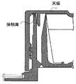
- FIG. 1 is a cross-sectional view showing a spout stopper according to an embodiment of the present invention.
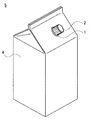
- FIG. 2 is a perspective view showing the packaging container according to the embodiment of the present invention.
- FIG. 3 is a cross-sectional view showing a spout stopper according to a modification of the present invention.
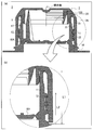
- FIG. 4 is a cross-sectional view showing the spout plug according to the embodiment of the present invention.
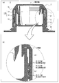
- FIG. 5 is a cross-sectional view showing the spout stopper according to the embodiment of the present invention.
- FIG. 6 is a cross-sectional view showing a state in which a cap is screwed onto the spout stopper according to the embodiment of the present invention.
- FIG. 1 is a cross-sectional view showing a spout stopper according to an embodiment of the present invention.
- FIG. 2 is a perspective view showing the packaging container according to the embodiment of the present invention.
- FIG. 3 is a cross-sectional view showing
- FIG. 7 is a cross-sectional view showing the spout plug according to the embodiment of the present invention.
- FIG. 8 is a bottom view, an enlarged view, and a partial cross-sectional view showing a spout stopper according to an embodiment of the present invention.
- FIG. 9 is a bottom view, an enlarged view, and a partial cross-sectional view showing a spout stopper according to a modification of the embodiment of the present invention.
- FIG. 1 shows a cross-sectional view of a spout plug 3 including a plug main body 1 and a cap 2.
- FIG. 2 the perspective view of the packaging container 5 containing the spout stopper 3 which consists of the stopper main body 1 and the cap 2, and the container main body 4 is shown.
- screw means that the threads of the cap and the side wall of the cap body are engaged with each other, and these are fitted (attached) by rotating them relatively in the circumferential direction.
- the “screw shaft” is an imaginary line that is on the center of the circumference formed by the thread and extends in the direction in which the cap moves when the cap and the plug body are screwed together.
- the spout plug 3 includes a plug body 1 and a cap 2.
- the plug body 1 has a cylindrical side wall 11.
- a top surface 109 is formed on the side wall 11 on the upper end side which is one end.
- the cap 2 includes a cylindrical side wall 21, a top plate 24, and a contact surface 27 formed perpendicular to the screwing shaft. The cap 2 is attached from the upper end side of the side wall 11 of the plug body 1.
- a protrusion 15 protruding outward from the side wall 11 is formed at the upper end edge of the side wall 11, and the top surface 109 of the upper end of the side wall 11 is in a state where the cap 2 is attached to the side wall 11 of the plug body 1. Surface contact is made with the contact surface 27 of the cap 2.
- the protrusion 15 is formed so as to protrude outward from the upper end edge of the side wall 11 of the plug body 1 to improve the liquid drainage performance when the content liquid is poured out. It is possible to prevent the plug body 1 from getting dirty and dirty.
- the upper end of the side wall 11 of the plug body 1 refers to the upper side of the side wall 11 in FIG.
- a disc-shaped flange portion 16 extending outward is formed on the lower end edge of the side wall 11 of the plug body 1. As shown in FIG. 2, the flange portion 16 is formed between the container body 4 and the spout stopper 3 when the packaging container 5 including the container body 4 and the spout stopper 3 attached to the container body 4 is manufactured. It becomes a joint location. Ultrasonic welding can be used as the bonding method.
- a cylindrical first outer diameter portion 13 and a cylindrical second outer diameter portion 14 having an outer diameter larger than this are provided below the protrusion 15 provided on the upper end of the side wall 11 of the plug body 1. And have. On the outer peripheral surface 17 of the second outer diameter portion 14, an outer screw 12 that can be screwed with an inner screw 22 of the cap 2 described later is formed.
- the cap 2 includes a cylindrical side wall 21 having an inner screw 22 formed on the inner peripheral surface 23, and a top plate 24 that covers the side wall 21 from the upper end side.
- the side wall 21 and the top plate 24 are connected by a thick portion 26 provided from the upper end side of the side wall 21 to the outer periphery of the top plate 24.
- a cylindrical inner ring 25 is formed on the inner side of the cap 2 so that one end thereof is in contact with the top plate 24 and is formed adjacent to the thick portion 26.
- a contact surface 27 perpendicular to the screwing shaft is formed at the lower end of the thick portion 26.
- the height of the contact surface 27 is such that the top surface 109 of the side wall 11 is in surface contact over the entire circumference when the cap 2 is mounted on the side wall 11 of the plug body 1.
- the side wall 11 is formed to be elastically deformed by receiving a compressive load.
- the outer peripheral surface of the inner ring 25 is formed so as to be in contact with the inner peripheral surface 19 of the side wall 11 in a state in which a part thereof protrudes over the entire periphery and the cap 2 is mounted on the side wall 11 of the plug body 1. .
- the cap 2 when the cap 2 is attached to the side wall 11 of the spigot main body 1, the cap 2 is rotated in the circumferential direction with respect to the side wall 11 after the cap 2 is covered from the upper end of the side wall 11.
- the outer screw 12 and the inner screw 22 are screwed together.
- the top surface 109 at the upper end of the side wall 11 comes into surface contact with the contact surface 27 of the cap 2 as described above, and the side wall 11 of the plug body 1 is elastically deformed.
- the outer peripheral surface of the inner ring 25 is in contact with the inner peripheral surface 19 of the side wall 11.
- the contact area with the contact surface 27 can be ensured larger than before, and the sealing performance can be improved.
- the contact surface 27 is formed so that the side wall 11 is elastically deformed. Therefore, the top surface 109 is in surface contact with the contact surface 27 with a high contact pressure. Thus, the sealing performance can be improved.
- the side wall 11 of the spigot body 1 receives a downward force from the contact surface 27 on the top surface 109 and the protrusion 15 as shown by an arrow A in FIG.
- the outer ring 25 receives an outward force as indicated by an arrow B in FIG. Therefore, the side wall 11 receives a force obliquely downward as indicated by an arrow P in FIG. 1B due to the resultant force of these forces, and the side wall 11 is elastically deformed in the direction in which it is spread.
- the side wall 11 of the plug body 1 comes into contact with the cap 2 so as to press the top surface 109 against the contact surface 27 and the inner peripheral surface 19 against the outer peripheral surface of the inner ring 25 by restoring force. For this reason, the sealing performance by the plug main body 1 can be further improved. This force is within the range of elastic deformation, and the side wall 11 immediately returns to its original shape after the cap 2 is opened.
- the contact pressure with respect to the contact surface 27 of the side wall 11 of the plug body 1 is increased, the torque necessary for the rotation of the cap 2 (hereinafter referred to as opening torque) is increased, and the cap 2 can be prevented from loosening. it can.
- opening torque the torque necessary for the rotation of the cap 2
- the cap 2 can be prevented from loosening. it can.
- the lead angle of the screw is formed large, the number of rotations until the screwing is completed can be reduced.
- the cap is easy to loosen. Since the cap can be prevented from loosening by applying the cap body, it is possible to provide a cap body that is difficult to loosen the cap while reducing the number of rotations until the screwing is completed.
- the rigidity of the cap 2 is preferably higher than the rigidity of the side wall 11 of the plug body 1.
- low-density polyethylene resin LDPE, L-LDPE
- polypropylene resin, high-density polyethylene resin, or the like can be used for the material of the cap 2.
- FIG. 3 shows a modification of this embodiment.
- the lower end of the thick portion 26 is formed in parallel with the top plate 24 to form the contact surface 27.
- the part may be a contact surface.
- the mode of contact between the side wall of the spout main body and the cap is not limited to the above-described embodiment and its modifications, and there is a contact mark that the side wall contacts the cap over the entire circumference and leads to deterioration of the content liquid drainage performance. It goes without saying that the position and shape can be arbitrarily selected as long as they do not remain on the side wall.
- the shape of the upper end of the side wall of the spigot body can be implemented in various ways depending on the design of the protrusions for preventing dripping, for example.
- the upper surface curved surface or curved surface or the chamfered portion near the outer side that continues from the uppermost end, not the exact uppermost end, such as the top surface of the upper end of the side wall of the plug body.
- Flat surface or, if a protrusion is provided, the outer end of the protrusion may contact a chamfered portion (curved surface or flat surface) that is not a strictly horizontal surface near the upper end of the inner peripheral surface of the side wall of the cap. Good.
- the external screw 12 on the side wall 11 of the plug body 1 and the internal screw 22 of the cap 2 may be a single thread or a multiple thread.
- a screw cap type cap body that is threaded on the cap 2 and the side wall 11 of the cap body 1 and is screwed together is used, but the top surface 109 of the side wall 11 and the cap 2 Any kind of plug body may be used as long as the plug body can be sealed by surface contact with the contact surface 27.
- the present invention can also be applied to a stopper cap in which a stopper main body for stoppering a container mouth portion and a cap for closing the stopper main body are connected by a hinge.
- FIG. 4 shows a cross-sectional view (a) of the spout stopper 3 in a state where the cap 2 is screwed, and an enlarged view (b) thereof.
- the plug body 1 is formed at the lower end of the side wall 11 and has a partition wall 104 that separates the upper end side and the lower end side inside the side wall 11.
- the upper end of the side wall 11 refers to one end on the side to which the cap 2 is screwed (upper side in FIG. 4).
- the partition wall 104 includes a pull ring 103.
- the user of the spout stopper 3 can open the side wall 11 by connecting the upper end side and the lower end side thereof by pulling out the partition wall 104 using the pull ring 103.
- an abutting portion 28 which is a region where the upper end portion of the side wall 11 of the plug body 1 is in surface contact over the entire circumference is provided, and higher sealing performance is obtained.
- the abutting portion 28 only needs to abut the upper end portion of the side wall 11 or the vicinity thereof in the screwed state over the entire circumference, and in the cap 2, the outer peripheral surface of the inner ring 25, the portion near the upper end of the inner peripheral surface of the side wall 21, You may provide in any of the top
- the range (L2) in which the external screw 12 is formed extends from the connection position with the flange portion 16 of the side wall 11 along the screwing shaft direction of the plug body 1. This is a range from 1/3 to 2/3 of the distance (L1) between the connection position and the upper edge.
- the connection position with the flange part 16 of the side wall 11 is a position of the upper surface of the flange part 16, and the height of the upper surface of the part which opposes the lower end of the side wall 21 of the cap 2 is shown in FIG. When it is higher than the height of the outer upper surface, it means the position of the upper surface of the portion facing the lower end of the side wall 21, which is the higher portion.
- the lower end position where the external screw 12 is formed may not be strictly the connection position with the flange portion 16 of the side wall 11.
- the outer screw 12 that does not engage with the inner screw 22 may not be formed.
- the lower end position of the outer screw 12 is about one pitch of the screw thread from the connection position with the flange portion 16. It may be upward.
- the overrun in which the outer screw 12 and the inner screw 22 get over each other is likely to occur when the inner screw 22 is pushed inward when the rigidity of the cap body 1 is lower than the rigidity of the cap 2, and conversely high. Such a case is likely to occur when the cap 2 is pushed outward.
- the rigidity of the plug body 1 and the cap 2 may be higher than the rigidity of the material used for the side wall 11 of the plug body 1.
- a polypropylene resin or a high density polyethylene resin can be used for the material of the cap 2
- a low density polyethylene resin can be used for the side wall 11 of the spigot body 1.
- the bending elastic modulus of the material of the cap 2 is, for example, 1000 MPa to 1500 MPa, and the bending elastic modulus of the material of the side wall 11 of the plug body 1 is, for example, 100 MPa to 200 MPa. If the bending elastic modulus of the material of the cap 2 is less than 1000 MPa, the cap 2 is easily deformed. Therefore, when an excessive rotational load is applied to the cap 2, the diameter of the inner screw 22 expands, and the inner screw 22 becomes the outer screw 12. Overrun is likely to occur. On the other hand, when the pressure is higher than 1500 MPa, the inner ring 25 is hardly elastically deformed and creep-deformed, so that the sealing performance is lowered.
- the inner screw 22 pushes the side wall 11 of the plug body 1 inward and the inner screw 22 is removed. Overrun is likely to occur over the screw 12.
- it is larger than 200 MPa, it is difficult to be deformed and strength is generated, and it becomes difficult to pull out and open the partition wall 104 using the pull ring 103.
- the external screw 12 in a range from a connection position with the flange portion 16 of the side wall 11 to a distance of 1/3 to 2/3 of the distance (L1) between the connection position and the upper edge, That is, by providing in a range including a portion near the lower portion of the side wall 11 whose rigidity is increased by the flange portion 16 and the partition wall 104, the side wall 11 is deformed inward even when the outer screw 12 is pushed by the inner screw 22. It is possible to make it difficult to generate overrun.
- the cap 2 When the range in which the external screw 12 is formed is less than one third of the distance (L1) between the connection position of the side wall 11 and the flange portion 16 of the side wall 11 and the upper edge of the side wall 11, the cap 2 The inner screw 22 is engaged only at the lower end portion of the cap 2 whose diameter is likely to expand, and the number of turns of the outer screw 12 is reduced, so that sufficient engagement is difficult to obtain. Further, when the range in which the external screw 12 is formed is greater than two thirds of the distance (L1) between the connection position of the side wall 11 and the flange portion 16 of the side wall 11 and the upper end edge of the side wall 11, the side wall 11.
- the portion where the external screw 12 is not formed is shortened, and when the cap 2 is inserted into the plug body 1, the cap 2 does not function as a guide for aligning the rotating shaft of the cap 2 with the screwing shaft of the screw. It becomes difficult to properly engage the screw.
- the plug body 1 manufactured by injection molding may be provided so that the taper is widened from the upper end to the lower end of the side wall 11 in order to improve the removal from the mold. For this reason, the thickness of the side wall 11 is larger at the lower end than the upper end, and the rigidity of the side wall 11 is larger at the lower end side. Therefore, when the taper is provided, the effect of suppressing the occurrence of overrun can be obtained even by the taper by forming the external screw 12 of the plug body 1 in the above-described range.
- the cap 2 may be provided with a taper whose diameter increases from the upper end toward the lower end.
- the range where the external screw 12 is formed is at least one third of the distance (L1) between the connection position of the side wall 11 and the flange portion 16 of the side wall 11 and the upper end edge of the side wall 11. Sufficiently engages with the screw and suppresses overrun.
- an area where the external screw 12 is not formed increases on the upper end side of the side wall 11.
- the region serves as a guide when the cap 2 is fitted, and the cap 2 is easily screwed and screwed along the screwing shaft. Further, even if the content liquid adheres to the area, it is easy to wipe it off.
- FIG. 5 shows a cross-sectional view (a) of the spout stopper 1 in a state where the cap 2 is screwed, and an enlarged view (b) thereof.
- the plug body 1 has a guide portion 113 that is an area on the upper end side of the external screw 12 and is not formed with an external screw.
- the distance (L3) is formed smaller than the length (L4) of the guide portion 113, which is the distance from the upper end edge of the side wall 11 of the plug body 1 to the outer screw portion formation start position on the upper end side of the outer screw 12. .
- FIG. 6 is a cross-sectional view showing how the cap 2 is screwed onto the side wall 11 of the spigot body 1.
- the user puts the cap 2 on the side wall 11 of the plug body 1 from the upper end ((a) in FIG. 6).
- the posture of the cap 2 may be inclined with respect to the screwing shaft direction due to contact between the protruding portion 15 and the inner screw 22 or the like.
- the user starts to insert the cap 2 in the screwing axis direction ((b) of FIG. 6).
- the inner screw 22 and the outer screw 12 are not in contact with each other.
- the inner screw 22 faces the guide portion 113, when the inclination amount of the cap 2 is larger than a predetermined amount, the inner screw 22 contacts the guide portion 113 to receive resistance, and the insertion progresses.
- the inclination amount of the cap 2 is gradually reduced.
- the guide portion 113 may have a portion whose outer diameter increases toward the outer screw 12 on the lower end side from the protrusion portion 15.
- the guide portion 113 is formed on the first outer diameter portion 13 formed on the lower end side of the projection portion 15, on the lower end side of the first outer diameter portion 13 and on the upper end side of the outer screw 12, You may have the 2nd outer diameter part 14 whose outer diameter is larger than the outer diameter part 13 of one.
- the lower end of the cap 2 passes through the second outer diameter portion 14 having a larger outer diameter after passing through the first outer diameter portion 13, so that the lower end of the cap 2 is started when the cap 2 starts to be inserted. Since the distance between the first outer diameter portion 13 and the first outer diameter portion 13 is large, the insertion can be facilitated. During the subsequent insertion, the distance between the lower end of the cap 2 and the second outer diameter portion 14 becomes small. The amount of inclination of can be reduced smoothly.
- the user continues to insert the cap 2 to a position where the inner peripheral surface 23 of the side wall 21 of the cap 2 faces the top of the external thread 12 of the side wall 11 of the plug body 1 ((c) of FIG. 6). ). Since the inclination of the cap 2 is reduced, the insertion proceeds smoothly. Even when the inclination is not completely eliminated, when the inner peripheral surface 23 passes through the top of the thread of the external screw 12, it abuts on the top of the thread and receives resistance. At almost the same time, the top of the inner thread 22 contacts the outer peripheral surface 17 of the second outer diameter portion 14 and receives resistance. As a result, the amount of inclination of the cap 2 is further reduced as the insertion proceeds.
- the user continues to insert the cap 2 until the lower end side of the inner screw 22 is in contact with the upper end side of the outer screw 12 ((d) in FIG. 6). Thereby, the inner screw 22 and the outer screw 12 come into contact with each other. At this stage, the inclination of the cap 2 with respect to the side wall 11 is eliminated. For this reason, when the user rotates the cap 2, the cap 2 and the side wall 11 of the plug body 1 can be easily screwed together without causing poor screwing.
- the distance (L3) between the formation start position that is the upper end of the inner screw 22 and the formation end position that is the lower end is outside the upper edge of the side wall 11 of the plug body 1. It is smaller than the guide portion length (L4) which is the distance to the formation start position on the upper end side of the screw 12. Therefore, the cap 2 from when the lower end of the cap 2 passes near the upper end of the side wall 11 of the plug body 1 until the inner screw 22 of the cap 2 contacts the outer screw 12 of the side wall 11 of the plug body 1.
- the insertion distance (L4 or more) can be made longer than the moving distance (about L3) of the cap 2 as the subsequent screwing progresses.
- the inner screw 22 of the cap 2 and the outer screw 12 of the side wall 11 of the plug body 1 can be engaged. Further, since the insertion distance is long, when the projection 15 and the inner screw 22 come into contact with each other at the start of insertion, the user erroneously determines that the outer screw 12 and the inner screw 22 are in contact with each other, and the cap 2 It is possible to prevent rotation from starting and screwing to fail.
- the thread portion is formed by a multi-threaded screw
- a plurality of screw threads start to be engaged at the same time during the screwing.
- the allowable value of the inclination amount of the cap for preventing the occurrence of screwing failure is smaller than that of the single-threaded screw. Therefore, the present invention provides a particularly remarkable effect when used for a spout stopper in which a multi-threaded screw is formed.
- the cap can be rectified, so that the restriction on the shape of the upper end of the side wall is reduced.
- the protrusion amount of the protrusion for preventing dripping can be increased within the range of the cap inner diameter, and the outer diameter of the upper end of the side wall can be made larger than the outer diameter of the outer screw.
- FIG. 7 sectional drawing of the plug main body 1 is shown.
- 8A is a bottom view of the plug body 1
- FIG. 8B is an enlarged view of the rib 108
- FIG. 8C is a cross-sectional view of the rib 108 along the line BB ′ (FIG. 2B).
- the cross section shown in FIG. 7 is a vertical cross section along the line A-A ′ shown in FIG.
- the plug body 1 is provided with a cylindrical side wall 11, a partition wall 104 that closes the inside of the side wall 11, and a half cut 141 is formed on the outer periphery, and extends outward from the lower end edge of the side wall 11.
- the disc-shaped flange portion 16, the groove-shaped meat stealing portion 18 provided concentrically with the side wall 11 on the surface opposite to the side wall 11 of the flange portion 16, and the inner surface of the meat stealing portion 18 are provided.
- the lower end of the side wall 11 refers to the lower side of the sheet of FIG.
- three projecting portions 119 projecting outward from the side wall 11 are formed equally on the circumference. .
- the number of protrusions 119 may be more than three.
- the partition wall 104 is connected to the side wall 11 through a half cut 141 in which the outer peripheral wall thickness is formed in an annular shape.
- a pull ring 103 is connected to the partition wall 104 via a support column. The user of the spigot body 1 pulls the pull ring 103 upward, pulls out the partition wall 104 broken along the half cut 141 from the side wall 11, and opens the upper end side and the lower end side of the side wall 11 to communicate with each other. Can do.
- the flange portion 16 is formed between the container body 4 and the spout stopper 3 when the packaging container 5 including the container body 4 and the spout stopper 3 attached to the container body 4 is manufactured. It becomes a joint location. Ultrasonic welding can be used as the bonding method.
- the side wall 11 of the stopper body 1 is inserted into the opening of the container body 4 from the inner surface side, and as shown in FIG. Is applied to the inner surface of the container body 4.
- the plug body 1 is temporarily fastened to the container body 4 by sandwiching the peripheral portion of the opening of the container body 4 between the protruding portion 119 and the flange portion 16.
- an anvil and an ultrasonic horn both not shown
- inserted into the inside (inner side) of the container body 4 are directed onto the container body 4 overlapping the flange portion 16 to generate ultrasonic vibrations.
- the flange portion 16 are welded. The vibration generated at this time is transmitted from the flange portion 16 through the side wall 11 to the partition wall 104, but part of the vibration is absorbed by the meat stealing portion 18.
- the meat stealing portion 18 is a groove provided concentrically on the outer periphery of the side wall 11 on the surface opposite to the side wall 11 of the flange portion 16.
- the cross section of the meat stealing portion 18 is an inverted U-shape (dome shape) having a strong resistance to ultrasonic vibration and a rounded top surface.
- the meat stealing portion 18 suppresses (disperses) the propagation of ultrasonic vibration to the partition wall 104, thereby preventing the half cut 141 of the partition wall 104 from cracking.
- ribs 108 are provided side by side on the inner peripheral surface of the meat stealing portion 18.
- the length L5 of each of the plurality of ribs 108 may be 0.3 mm or more along the circumferential direction of the meat stealing portion 18, If it is 0.5 mm or more, the mold can be easily produced, and it is still preferable.
- L5 is preferably 1.5 mm or less.
- interval L6 between the adjacent ribs 108 is in the range of 0.5 mm or more and 5.0 mm or less.
- the energy of ultrasonic vibration is absorbed and dispersed to a certain extent by the ribs 108, co-vibration is suppressed in the vicinity of the flange portion 16 and the meat stealing portion 18 of the side wall 11, and uneven concentration of energy is eliminated. As a result, it can suppress that the flange part 16 and the side wall 11 deform
- the entire circumference of the meat stealing portion 18 is divided into 24 by 24 ribs 108.
- the number of divisions is 6 or more and 30 or less by 6 or more and 30 or less ribs. It is preferable.
- the spout stopper 1 capable of suppressing deformation of each part due to ultrasonic welding and the packaging container 5 using the same. Furthermore, production efficiency can be improved by increasing the vibration energy at the time of ultrasonic welding or shortening the vibration cycle. Further, the cost can be reduced by reducing the thickness of the half cut 141.
- the shape of the meat stealing part 18 is not restricted to the example shown in FIG. 9A is a bottom view of the plug body 1 according to a modification, FIG. 9B is an enlarged view of the rib 108, and FIG. 9C is the rib 108 along the line BB ′ (see FIG. 9B). ) Shows a cross-sectional view cut in the circumferential direction.
- the cross-sectional shape of the meat stealing portion 18 along the line AA ′ has a U-shaped round shape as shown in FIG. 7, but is similar to the example shown in FIG. Further, it may have a linear shape composed of a taper and a substantially flat top surface.
- present invention is not limited to the above-described embodiment.
- present invention can also be implemented as an outlet plug and a packaging container equipped with these.
- Example 1-1 As Example 1-1, the plug body 1 according to the above-described embodiment shown in FIG. 1 in which the protrusion 15 was formed on the upper edge of the side wall 11 of the plug body 1 was used.
- Reference Example 1-1 As Reference Example 1-1, a plug body in which a shape corresponding to the protrusion 15 of the plug body 1 was not formed was used. Others were the same as the plug body 1.
- Example 1-1 Samples of Example 1-1 and Reference Example 1-1 were prepared. Immediately after setting (attaching the spout stopper to the container body), immediately after filling the content liquid (3 days after setting, 70 ° C.), 1 day after filling The opening torque (N ⁇ cm) after 7 days after filling and 14 days after filling was measured. The test results are shown in Table 1.
- the plug body according to Reference Example 1-1 has a tendency to decrease the opening torque after filling.
- the plug body 1 according to the example does not show a significant decrease in the opening torque even after 14 days from filling. From this result, it is possible that the plug body 1 according to Example 1-1 can maintain a state in which the cap is less likely to loosen compared to the plug body according to Reference Example 1-1 for a longer period of time. It was confirmed that the sealing performance was higher.
- Example 2-1 of the present invention is the spout plug 1 according to the above-described embodiment whose sectional view is shown in FIG.
- the external screw 12 is formed in a range from a connection position with the flange portion 16 to a height of 60% of the distance between the connection position and the upper end edge.
- the cap 2 was made of polypropylene having a bending elastic modulus of 1470 MPa
- the plug body 1 was made of low density polyethylene having a bending elastic modulus of 120 MPa.
- Example 2-2 In Example 2, the formation range of the external screw 12 is changed in Example 2-1, and the range from the connection position with the flange portion 16 to a height of 58.7% of the distance between the connection position and the upper end edge is set. Formed.
- the above-mentioned L1 was 12.70 mm and L2 was 7.45 mm.
- Example 2-3 In Example 2-3, the formation range of the external screw 12 is changed in Example 2-1, and the range from the connection position with the flange portion 16 to a height of 55% of the distance between the connection position and the upper end edge is set. Formed.
- the above-mentioned L1 was 14.34 mm and L2 was 7.89 mm.
- Reference Example 2-1 changes the formation range of the external screw 12 in Example 2-1 to a range from the connection position with the flange portion 16 to a height of 70% of the distance between the connection position and the upper edge. Formed.
- Reference Example 2-2 In Reference Example 2-2, the formation range of the external screw 12 was changed in Example 2-1, and the range from the connection position with the flange portion 16 to a height of 75% of the distance between the connection position and the upper end edge was changed. Formed.
- Examples 3-1 to 3-9 are the spout plug 1 according to the above-described embodiment whose sectional view is shown in FIG. 5A, and the above-described L3 and L4 are L3 ⁇ L4.
- L3> L4 is set instead of L3 ⁇ L4.
- Examples 3-1, 3-2, 3-4, 3-5, 3-7, 3-8 and Reference Examples 3-1, 3-2, D1 and D2 described above are set to D1 ⁇ D2.
- Examples 3-3, 3-6, and 3-9 D1> D2.
- the guide portion is provided with a portion whose outer diameter increases toward the lower end, and Examples 3-2, 3-3, 3 and 3 are provided. ⁇ 5, 3-6, 3-8, 3-9 and Reference Example 3-2 were not provided with a portion having an increased outer diameter.
- the present invention can be used for plug bodies of various packaging containers such as paper packaging containers, plastic bottles, bottles, and flexible packaging containers.
Landscapes
- Engineering & Computer Science (AREA)
- Mechanical Engineering (AREA)
- Closures For Containers (AREA)
Abstract
口栓本体の液切れ性能を悪化させることなく、キャップとの密封性能の低下を防ぐ注出口栓及びこれを用いた包装容器を提供する。注出口栓は、円筒状の側壁を有する口栓本体と、側壁の一端である上端側から装着されるキャップとを備え、側壁の上端縁には、側壁の外方に突出する突起部が形成され、側壁の上端の天面は、キャップを側壁に装着させた状態において、キャップ内方の所定の接触面に全周にわたって面接触する。
Description
本発明は、注出口栓及び包装容器に関するものである。
飲料、液体調味料、化粧品等の製品の容器本体の注出口にネジ部が形成された注出口栓(スパウト)を設けて、これに螺合可能なネジ部を形成したキャップにより注出口を閉塞する技術が知られている。このような注出口栓及びキャップは、一旦キャップを取り外して開栓した後でも、ネジ部どうしを再び螺合することにより、繰り返してキャッピングが可能である。
特許文献1には、キャップ本体の密閉側の内面に、注出口の注出口本体(注出口栓)の先端と係合して密封性を高めるコンタクトリング及びインナーリングが設けられているキャップ本体が開示されている。
特許文献2には、スパウトの先端を紙容器傾斜板の傾斜角度と同じ角度で拡げて形成することで、内容液の注ぎ出し時に液ダレの発生が少なく液切れの良いスパウトを有する口栓が開示されている。
樹脂材料からなる注出口栓の容器本体への取り付けには、超音波振動を注出口栓が備えるフランジに加えて溶着する、超音波溶着法が多く用いられている。
特許文献3には、フランジ面の内縁近傍に肉盗み部(環状透かし部)を設けることで、超音波溶着時に発生する振動が、注出口栓を閉塞する隔壁(封鎖板)のハーフカット部(環状薄肉脆弱線)に伝わることを抑制しクラックが生じることを防ぐ注出口栓(プルリング付口栓)が開示されている。
特許文献4には、上述の肉盗み部を備えた注出口栓において、容器本体をフランジとの間で押さえるために側壁の周方向に等間隔に設けられる突起が、超音波振動のエネルギーにより変形することを抑制するために、肉盗み部の内面であって突起と対応する位置にリブを設け、超音波振動のエネルギーを分散、吸収させる技術が開示されている。
しかしながら、スパウトを溶着により容器本体に取り付ける場合には、スパウトの材質には低密度ポリエチレン樹脂を用い、キャップの材質にはこれよりも固い材質であるポリプロピレン樹脂または高密度ポリエチレン樹脂等を用いることが多い。このような材質を用いた場合に、コンタクトリングをキャップに形成すると、スパウトのコンタクトリングとの接触部には、コンタクトリングの係合跡が残りやすい。特に、スパウトに残ったコンタクトリングの係合跡は、スパウトの上端に円周状のV字型の溝として残り、注出される内容液の液切れ性能の悪化の原因となる。
本発明は、上述の課題を鑑みてなされたものであり、口栓本体の液切れ性能を悪化させることなく、キャップとの密封性能の低下を防ぐ注出口栓及びこれを用いた包装容器を提供することを目的とする。
また、このような口栓は、包装容器に溶着固定して用いられることが多い。このため、溶着後の、注出口栓と包装容器とのシール性を高める目的から、スパウトの材質には低密度ポリエチレン樹脂(LDPE、L-LDPE)がよく用いられる。このような場合には、キャップの材質には、低密度ポリエチレン樹脂と比較して剛性の高いポリプロピレン樹脂や高密度ポリエチレン樹脂等を用いることで、スパウトとキャップとの間での密封性を高めることができる。
しかしながら、スパウトの剛性がキャップの剛性より高いと、両者に過大なトルクがかかった場合に、剛性の低いスパウトがキャップの内ネジから受けた荷重により内周方向に倒れ込み、内ネジがスパウトのネジ部を乗り越える「オーバーラン」が発生することがある。オーバーランが発生すると、キャップとの螺合が不完全となり、内容液が漏出しやすくなる。また、オーバーランによりスパウトの外ネジの一部がキャップのネジ部により削られることにより、螺合に遊び(隙間)が生じ、注出口栓の密封性能が低下することがある。
本発明は、上述の課題を鑑みてなされたものであり、キャップ及び口栓本体に過大なトルクがかかった場合であっても、オーバーランの発生を抑えることができる注出口栓及びこれを用いた包装容器を提供することを目的とする。
また、このような口栓の場合、ネジ部どうしの螺着に際しては、キャップ及びスパウトそれぞれの螺合軸を一致させるようにしてキャップをスパウトに螺着して、その後キャップを回転させなければ、ネジ部どうしが正しくかみ合った状態で螺合されにくい。キャップ及びスパウトそれぞれの螺合軸が一致しておらず、キャップがスパウトに対して斜めにある状態で、使用者が無理にキャップを回転させようとすれば、螺合ができなかったり、ネジ山どうしが正しくかみ合わない不完全な状態で固定されたりするなどの螺合不良を生じやすい。
また、キャップのネジ部は、スパウトのネジ部に接触する前にスパウト先端の液だれ防止形状等に接触しやすい。このため、使用者が、キャップ及びスパウトの中心軸を一致させるようにしてキャップを注出口栓に螺着しようとしても、キャップのネジ部が液だれ防止形状に接触することで、キャップの姿勢が変えられて、キャップをスパウトに正しく螺合できずに螺合不良を生じることがある。
本発明は上述の課題を鑑みてなされたものであり、キャップ及び注出口栓のネジ部の螺合不良の発生を防止できる注出口栓及びこれを用いた包装容器を提供することを目的とする。
また、特許文献3、4のように、超音波溶着時の注出口栓の各部の変形を抑制するため、肉盗み部およびリブを設けることが提案されているが、その好適な設計については、充分検討されていなかった。
本発明は、上述の課題を鑑みてなされたものであり、超音波溶着による各部の変形を好適に抑制できる注出口栓及びこれを用いた包装容器を提供することを目的とする。
上記課題を解決するための本発明の一局面は、円筒状の側壁を有する口栓本体と、側壁の一端である上端側から装着されるキャップとを備え、側壁の上端縁には、側壁の外方に突出する突起部が形成され、側壁の上端の天面は、キャップを側壁に装着させた状態において、キャップ内方の所定の接触面に全周にわたって面接触する注出口栓である。
上記課題を解決するための本発明の他の局面は、外周面に外ネジが形成された円筒状の側壁をを含む口栓本体と、内周面に内ネジが形成された円筒状の側壁を含み、口栓本体の側壁の一端である上端側から螺着されるキャップとを備え、口栓本体の側壁の下端には、口栓本体の側壁の下端縁から外方に延伸して設けられた円盤状のフランジ部が形成され、外ネジは、螺合軸方向に沿って、口栓本体の側壁のフランジ部との接続位置から、当該接続位置と上端縁との距離の3分の1以上3分の2以下の距離までの範囲に形成されている、注出口栓である。
上記課題を解決するための本発明の他の局面は、円筒状の側壁を有する口栓本体と、側壁の一端である上端側から螺着されるキャップとを備え、側壁の外周面は、外ネジが形成された外ネジ部と、外ネジ部より上端側の領域である、外ネジが形成されていないガイド部とを有し、キャップの内周面は、外ネジと螺合する内ネジが形成された内ネジ部を有し、螺合軸方向に沿った、内ネジの上端である形成開始位置と下端である形成終了位置との間の距離は、側壁の上端縁から外ネジの上端側の形成開始位置までの距離であるガイド部長さより小さい、注出口栓である。
上記課題を解決するための本発明の他の局面は、円筒状の側壁と、側壁の内部を閉塞し、外周部にハーフカットが形成された隔壁と、側壁の下端縁から外方に延伸して設けられた円盤状のフランジ部とフランジ部の側壁とは反対側の面に、側壁と同心円状に設けられた溝状の肉盗み部と、肉盗み部の内面に設けられた複数のリブとを備え、複数のリブのそれぞれは、肉盗み部の周方向に沿って、隣接するリブとの間隔が0.5mm以上5.0mm以下である、注出口栓である。
また、本発明の他の局面は、容器本体と、容器本体に取り付けられた上述の注出口栓とを含む、包装容器である。
本発明に係る注出口栓は、口栓本体の液切れ性能を悪化させることなく、キャップとの密封性能の低下を防ぐことができ、また、キャップ及び口栓本体に過大なトルクがかかった場合であっても、オーバーランの発生を抑えることができ、また、キャップ及び口栓本体のネジ部の螺合不良を防止でき、また、超音波溶着による各部の変形を抑制できる。本発明により、このような注出口栓を用いた包装容器を提供することができる。
本発明の実施形態に係る注出口栓3及び包装容器5について、図1及び図2を参照して説明する。図1には、口栓本体1及びキャップ2を含む注出口栓3の断面図を示す。図2には、口栓本体1とキャップ2とからなる注出口栓3と、容器本体4とを含む包装容器5の斜視図を示す。なお、本明細書中において、「螺合」とは、キャップと口栓本体の側壁とのネジ山どうしをかみ合わせて、これらを相対的に円周方向に回転させることで両者を嵌合(装着)することをいう。また、「螺合軸」とは、ネジ山の形成する円周の中心上にあって、キャップと口栓本体とを螺合するのに際してキャップが移動する方向に延びる、架空の線のことをいう。
初めに、注出口栓3及び口栓本体1、キャップ2について説明する。
注出口栓3は、図1に示すように、口栓本体1とキャップ2とを備える。口栓本体1は、円筒状の側壁11を有する。側壁11には、一端である上端側に天面109が形成されている。キャップ2は、円筒状の側壁21と、天板24と、螺合軸に垂直に形成された接触面27とを有する。キャップ2は、口栓本体1の側壁11の上端側から装着される。側壁11の上端縁には、側壁11の外方に突出する突起部15が形成され、側壁11の上端の天面109は、キャップ2を口栓本体1の側壁11に装着させた状態において、キャップ2の接触面27に面接触する。突起部15を、口栓本体1の側壁11の上端縁から外方に突出して形成することで内容液注出時の液切れ性能を向上させ、注出時に内容液が側壁11の外周面を伝わり落ちて口栓本体1が汚れることを防止できる。なお、口栓本体1の側壁11の上端とは、側壁11の図1における紙面上方側をいう。
注出口栓3は、図1に示すように、口栓本体1とキャップ2とを備える。口栓本体1は、円筒状の側壁11を有する。側壁11には、一端である上端側に天面109が形成されている。キャップ2は、円筒状の側壁21と、天板24と、螺合軸に垂直に形成された接触面27とを有する。キャップ2は、口栓本体1の側壁11の上端側から装着される。側壁11の上端縁には、側壁11の外方に突出する突起部15が形成され、側壁11の上端の天面109は、キャップ2を口栓本体1の側壁11に装着させた状態において、キャップ2の接触面27に面接触する。突起部15を、口栓本体1の側壁11の上端縁から外方に突出して形成することで内容液注出時の液切れ性能を向上させ、注出時に内容液が側壁11の外周面を伝わり落ちて口栓本体1が汚れることを防止できる。なお、口栓本体1の側壁11の上端とは、側壁11の図1における紙面上方側をいう。
口栓本体1の側壁11の下端縁には、外方に延出する円盤状のフランジ部16が形成される。フランジ部16は、図2に示すように、容器本体4と、容器本体4に取り付けられた注出口栓3とを含む包装容器5を製造する際に、容器本体4と注出口栓3との接合箇所となる。接合方法には、超音波溶着を用いることができる。
口栓本体1の側壁11の上端に設けられた突起部15の下方には、円筒状の第1の外径部13と、これよりも外径が大きい円筒状の第2の外径部14とを有する。第2の外径部14の外周面17には、後述するキャップ2の内ネジ22と螺合可能な外ネジ12が形成されている。
キャップ2は、図1に示すように、内周面23に内ネジ22が形成された円筒状の側壁21と、側壁21を上端側から覆う天板24とを有する。側壁21と天板24とは、側壁21の上端側から天板24の外周へわたって設けられた肉厚部26により連結される。側壁21の内周面23には、口栓本体1の側壁11に形成された外ネジ12と螺合可能な内ネジ22が形成されている。キャップ2の内側には、その一端を天板24に接するとともに、肉厚部26に隣接して形成された、円筒状のインナーリング25が形成されている。肉厚部26の下端には、螺合軸に垂直な接触面27が形成されている。
図1の(b)に示すように、接触面27の高さは、キャップ2を口栓本体1の側壁11に装着した状態において、側壁11の天面109が全周にわたって面接触し、さらに、側壁11が圧縮荷重を受けることで弾性変形をするように形成されている。また、インナーリング25の外周面は、その一部が全周にわたって突出してキャップ2を口栓本体1の側壁11に装着した状態で、側壁11の内周面19と接触するように形成される。
本実施形態において、キャップ2を口栓本体1の側壁11に装着する際には、キャップ2を側壁11の上端から被せた後に、キャップ2を側壁11に対して円周方向に回転させることで外ネジ12及び内ネジ22を螺合する。外ネジ12及び内ネジ22の螺合が完了すると、上述のように、側壁11の上端の天面109がキャップ2の接触面27に面接触し、口栓本体1の側壁11が弾性変形をするとともに、インナーリング25の外周面が側壁11の内周面19と接触する。
本実施形態では、突起部15によって、天面109の面積を大きくすることによって、接触面27との接触面積を、従来と比較して大きく確保でき、密封性能を向上させることができる。
また、キャップ2を口栓本体1の側壁11に装着すると、側壁11が弾性変形をするように、接触面27を形成しているため、天面109は高い接触圧で接触面27に面接触して、密封性能を向上させることができる。
また、口栓本体1の側壁11は、天面109および突起部15に、接触面27から、図1の(b)の矢印Aで示すように下向きの力を受けるとともに、内周面18に、インナーリング25から、図1の(b)の矢印Bで示すように外向きの力を受ける。そのため、これらの力の合力によって側壁11は、図1の(b)の矢印Pで示すように斜め下向きに力を受け、側壁11は、押し広げられる方向に弾性変形することとなる。この結果、口栓本体1の側壁11は、復元力により、接触面27には天面109を、インナーリング25の外周面には内周面19を押し付けるようにして、キャップ2と接触する。このため、口栓本体1による密封性能をさらに向上させることができる。なお、この力は弾性変形の範囲内であって、キャップ2を開栓した後は側壁11は、直ちに元の形状に戻る。
また、口栓本体1の側壁11の接触面27に対する接触圧が大きくなることで、キャップ2の回転に必要なトルク(以下、開封トルクという)が大きくなり、キャップ2の緩みを防止することができる。一般に、ネジのリード角度を大きく形成した場合、螺合完了するまでの回転数を減らすことができる反面、キャップが緩みやすくなるが、リード角を大きく形成した口栓本体であっても、本発明を適用することでキャップの緩みを防止できるため、螺合完了するまでの回転数を減らしたまま、キャップの緩みにくい口栓本体を提供することができる。
キャップ2の剛性は、口栓本体1の側壁11の剛性よりも高いことが好ましい。例えば、口栓本体1の側壁11の材質には、低密度ポリエチレン樹脂(LDPE、L-LDPE)を用い、キャップ2の材質には、ポリプロピレン樹脂や高密度ポリエチレン樹脂等を用いることができる。このような関係にある材質を用いることで、口栓本体1の側壁11の弾性変形量が大きくなり、側壁11をパッキンのように用いることができ、密封性能をより高めることができる。
図3には、本実施形態の変形例を示す。本実施形態において、肉厚部26の下端を天板24と平行に形成して接触面27としたが、図3に示すように、肉厚部26にあたる部分を設けることなく、天板の一部を接触面としてもよい。口栓本体の側壁とキャップとの接触の態様は、上述の実施形態およびその変形例に限らず、側壁が全周にわたってキャップに接触し、かつ内容液の液切れ性能の悪化につながる接触跡が側壁に残らないかぎり、その位置、形状は任意に選択できることはいうまでもない。口栓本体の側壁の上端の形状は、例えば、液だれ防止のための突起部等の設計に応じて多様に実施可能である。また、キャップの形状も、多様に実施可能である。したがって、このような多様性に応じて、例えば、口栓本体の側壁の上端の天面のような、厳密な最上端ではなく、最上端から続くその外側近傍の面取り部分を含む上面(曲面あるいは平面)、あるいは、突起部を設けた場合は突起部の外方端部が、キャップの側壁の内周面の上端寄りの、厳密な水平面ではない面取り部分(曲面あるいは平面)に接触してもよい。
口栓本体1の側壁11の外ネジ12及びキャップ2の内ネジ22は、1条ネジであっても、多条ネジであってもよい。
本実施形態においては、キャップ2及び口栓本体1の側壁11にネジ山を形成して、互いに螺合するネジキャップ式の口栓本体を用いたが、側壁11の天面109とキャップ2の接触面27とが面接触することで口栓本体の密封ができれば、口栓本体の種類は何でもよい。例えば、容器口部に打栓する口栓本体と、口栓本体を閉塞するキャップとをヒンジにより結合した打栓キャップにも本発明は適用可能である。
本発明の実施形態を、図4を参照してさらに説明する。
図4には、キャップ2を螺合した状態の注出口栓3の断面図(a)と、その要部拡大図(b)を示す。口栓本体1は、側壁11の下端に形成され、側壁11内部の上端側と下端側とを隔てる隔壁104を有する。ここで、側壁11の上端とは、キャップ2が螺着される側(図4では紙面上方)の一端をいう。
隔壁104はプルリング103を備える。注出口栓3の使用者は、プルリング103を使って隔壁104を引き抜くことで、側壁11の上端側と下端側とを連通させて開口することができる。
インナーリング25と側壁21との間には、口栓本体1の側壁11の上端部分が全周にわたって面接触する領域である当接部28が設けられ、より高い密封性が得られる。当接部28は、螺着状態において側壁11の上端部分やその近傍が全周にわたって当接すればよく、キャップ2においてインナーリング25の外周面、側壁21の内周面の上端寄りの部分や、これらに挟まれる天面部分のいずれに設けられてもよい。
図4の(b)に示すように、外ネジ12の形成される範囲(L2)は、口栓本体1の螺合軸方向に沿って、側壁11のフランジ部16との接続位置から、当該接続位置と上端縁との距離(L1)の3分の1以上3分の2以下の距離までの範囲である。なお、側壁11のフランジ部16との接続位置とは、フランジ部16の上面の位置であり、図4に示すように、キャップ2の側壁21の下端に対向する部分の上面の高さがその外方の上面の高さより高い場合は、高い方の部分である、側壁21の下端に対向する部分の上面の位置をいう。また、外ネジ12が形成される下端位置は、厳密に側壁11のフランジ部16との接続位置でなくてもよい。例えば内ネジ22と係合しえない範囲の外ネジ12は、当然形成しなくてもよく、この場合、外ネジ12の下端位置はフランジ部16との接続位置からネジ山の1ピッチ分程度上方であってもよい。
外ネジ12、内ネジ22が互いを乗り越えるオーバーランは、口栓本体1の剛性がキャップ2の剛性より低い場合は、内ネジ22が内側に向かって押し込まれることによって発生しやすく、逆に高い場合は、キャップ2が外側に向かって押し広げられることによって発生しやすい。オーバーランを抑制するため、口栓本体1およびキャップ2の剛性を以下のように設定することが好ましい。例えば、キャップ2に用いられる材質の剛性は、口栓本体1の側壁11に用いられる材質の剛性よりも高くてもよい。例えば、キャップ2の材質には、ポリプロピレン樹脂又は高密度ポリエチレン樹脂を、口栓本体1の側壁11には、低密度ポリエチレン樹脂を用いることができる。また、キャップ2の材質の曲げ弾性率は、例えば1000MPa以上1500MPa以下とし、口栓本体1の側壁11の材質の曲げ弾性率は、例えば100MPa以上200MPa以下とすることが好ましい。キャップ2の材質の曲げ弾性率が、1000MPa未満であると、変形しやすいため、キャップ2に過大な回転荷重がかかった場合に、内ネジ22の径が広がって、内ネジ22が外ネジ12を乗り越えて、オーバーランが発生しやすくなる。また、1500MPaより大きいと、インナーリング25が弾性変形しにくく、クリープ変形するため密封性が低下する。口栓本体1の側壁11の材質の曲げ弾性率が、100MPa未満であると、変形しやすいため、内ネジ22が口栓本体1の側壁11を内側へ向かって押し込んで、内ネジ22が外ネジ12を乗り越えて、オーバーランが発生しやすくなる。また、200MPaより大きいと、変形しにくく強度が生じ、プルリング103を使って隔壁104を引き抜いて開口することが困難になる。
外ネジ12を、側壁11のフランジ部16との接続位置から、当該接続位置と上端縁との距離(L1)の3分の1以上3分の2以下の距離までの範囲に設けることによって、すなわち、フランジ部16や隔壁104によって剛性が高くなっている側壁11の下部寄りの部分を含む範囲に設けることによって、内ネジ22によって外ネジ12が押されても、側壁11が内側に変形しにくくすることができ、オーバーランを発生しにくくすることができる。
外ネジ12の形成される範囲が、側壁11のフランジ部16との接続位置から、当該接続位置と側壁11の上端縁との距離(L1)の3分の1未満である場合、キャップ2の内ネジ22とは、径が広がりやすいキャップ2の下端部分のみで係合することになり、また、外ネジ12の巻き数が少なくなり、十分な係合が得られにくい。また、外ネジ12の形成される範囲が、側壁11のフランジ部16との接続位置から、当該接続位置と側壁11の上端縁との距離(L1)の3分の2より大きい場合、側壁11の外ネジ12が形成されていない部分が短くなり、キャップ2を口栓本体1に挿入する際に、キャップ2の回転軸とネジの螺合軸とを一致させるガイドとしての機能を果たさなくなり、ネジを正しく係合させにくくなる。
また、射出成型で製造される口栓本体1は、金型からの抜けを向上するため、テーパが、側壁11の上端から下端に向かって広がるようにつけられてもよい。このため、側壁11の厚みは、上端より下端が大きくなり、側壁11の剛性は、下端側がより大きい。したがって、テーパを設けた場合、口栓本体1の外ネジ12を上述の範囲に形成することで、テーパによっても、オーバーランの発生を抑える効果が得られる。なお、キャップ2にも同様に上端から下端に向かって径が広がるテーパが設けられてもよい。この場合でも、外ネジ12の形成される範囲が、側壁11のフランジ部16との接続位置から、当該接続位置と側壁11の上端縁との距離(L1)の3分の1以上であれば、十分にネジがかみ合い、オーバーランの発生を抑えることができる。
また、従来技術に係る注出口栓では、側壁の剛性を高めてオーバーランを抑えるために、側壁への外ネジの巻き数を増やす方法も採られていた。しかしながら、本実施形態では、外ネジ12を上述の範囲に形成することで、オーバーランの発生を抑えることができるため、外ネジ12の側壁への巻き数を、従来よりも減らすことができる。このため、注出口栓3の使用者は、従来の注出口栓と比較して、より少ない回転数で容易にキャップ2の螺合及び取り外しをすることができる。
また、側壁11の上端側には、外ネジ12の形成されていない領域が増える。この結果、当該領域がキャップ2を嵌める際のガイドとなって、螺合軸に沿ったキャップ2の螺着・螺合が容易になる。また、当該領域に内容液が付着した場合であってもこれを拭き取りやすくなる。
本発明の実施形態について、図5、6を参照してさらに説明する。
図5には、キャップ2を螺合した状態の注出口栓1の断面図(a)と、その要部拡大図(b)を示す。口栓本体1は、外ネジ12より上端側の領域であり外ネジが形成されていないガイド部113を有する。
図5の(b)に示すように、内ネジ22の、螺合軸方向に沿った、内ネジ22の上端である内ネジ部形成開始位置と下端である内ネジ部形成終了位置との間の距離(L3)は、口栓本体1の側壁11の上端縁から外ネジ12の上端側の外ネジ部形成開始位置までの距離であるガイド部113の長さ(L4)より小さく形成される。
また、図6の(c)に示すように、キャップ2を口栓本体1の側壁11に螺合軸に沿って嵌合させた状態において、キャップ2の側壁21の内周面23と、口栓本体1の側壁11に形成された外ネジ12のネジ山頂部との間の距離(D1)は、キャップ2の内ネジ22のネジ山頂部とガイド部113の外周面18との間の距離(D2)より小さく形成されてもよい。
図6には、口栓本体1の側壁11にキャップ2を螺着する様子を示す断面図を示す。
初めに、使用者は、キャップ2を口栓本体1の側壁11に上端からかぶせる(図6の(a))。この際、突起部15と内ネジ22とが接触すること等により、キャップ2の姿勢が螺合軸方向に対して傾くことがある。
次に、使用者は、キャップ2を螺合軸方向に向かって挿入を開始する(図6の(b))。図示する段階では、内ネジ22と外ネジ12とは接触しない。また、内ネジ22が、ガイド部113に面するため、キャップ2の傾き量が所定量より大きい場合には、内ネジ22がガイド部113に当接することにより抵抗を受け、挿入の進行に伴って、キャップ2の傾き量が、徐々に軽減される。
ガイド部113は、突起部15より下端側に外ネジ12に向かって外径が大きくなる部分を有してもよい。例えば、ガイド部113は、突起部15の下端側に形成される第1の外径部13と、第1の外径部13の下端側であって外ネジ12の上端側に形成され、第1の外径部13より外径が大きい第2の外径部14とを有してもよい。この場合、キャップ2の下端は、第1の外径部13の通過後に、より外径が大きい第2の外径部14を通過することによって、キャップ2の挿入開始時は、キャップ2の下端と第1の外径部13との距離が大きいため挿入しやすくすることができ、その後の挿入進行時に、キャップ2の下端と第2の外径部14との距離が小さくなるため、キャップ2の傾き量は、スムーズに軽減することができる。
使用者は、引き続き、キャップ2の側壁21の内周面23が、口栓本体1の側壁11の外ネジ12のネジ山頂部に面する位置までキャップ2を挿入する(図6の(c))。キャップ2の傾きが軽減されているため、挿入はスムーズに進行する。傾きが完全に解消していない場合であっても、内周面23が外ネジ12のネジ山頂部を通過する際、ネジ山頂部に当接して抵抗を受ける。またこれとほぼ同時に、内ネジ22のネジ山頂部が第2の外径部14における外周面17に当接し抵抗を受ける。これらにより、挿入の進行に伴って、キャップ2の傾き量が、さらに軽減される。
使用者は、引き続き、内ネジ22の下端側が、外ネジ12の上端側に接する位置までキャップ2を挿入する(図6の(d))。これにより、内ネジ22と外ネジ12とが接触する。この段階では、キャップ2の側壁11に対する傾斜は解消している。このため、使用者が、キャップ2を回転させると、螺合不良を発生させることなく、キャップ2と口栓本体1の側壁11とを容易に螺合させることができる。
本実施形態に係る注出口栓においては、内ネジ22の上端である形成開始位置と下端である形成終了位置との間の距離(L3)は、口栓本体1の側壁11の上端縁から外ネジ12の上端側の形成開始位置までの距離であるガイド部長さ(L4)より小さい。そのため、キャップ2の下端が口栓本体1の側壁11の上端近傍を通過してから、キャップ2の内ネジ22と口栓本体1の側壁11の外ネジ12とが接触するまでの、キャップ2の挿入距離(L4以上)を、その後の螺合進行にともなうキャップ2の移動距離(L3程度)より長くすることができる。すなわち、キャップ2の挿入が進行し、キャップ2の傾きが確実に軽減された後に、キャップ2の内ネジ22と口栓本体1の側壁11の外ネジ12とがかみ合うようにできる。また、挿入距離が長いため、挿入開始時に突起部15と内ネジ22とが接触した場合に、これを外ネジ12と内ネジ22とが接触したものと使用者が誤判断してキャップ2の回転を開始し螺合に失敗することを防ぐことができる。
また、本実施形態に係る注出口栓においては、キャップ2の側壁21の内周面23と、口栓本体1の側壁11に形成された外ネジ12のネジ山頂部との間の距離(D1)より、キャップ2の内ネジ22のネジ山頂部とガイド部113の外周面17との間の距離(D2)が大きいことが好ましい。これにより、図6の(c)に示すように、キャップ2の下端と口栓本体1の側壁11の内ネジ22との干渉により、螺合軸の位置合わせを精度よく行う(精度D1)ことができるとともに、キャップ2の下端以外の箇所で、口栓本体1の側壁11との間で、一定のクリアランスD2(>D1)により不要な干渉を抑制できるため、外ネジ12と内ネジ22との螺合時のかみ合いをよりスムーズにすることができる。
また、ネジ部を多条ネジで形成した場合には、螺合に際して、複数のネジ山が同時にかみ合いを開始する。このため、一般に、多条ネジは、1条ネジと比較して螺合不良を発生しないためのキャップの傾き量の許容値は小さくなる。したがって、本発明は、多条ネジが形成されている注出口栓に用いることで、とくに顕著な効果が得られる。
また、キャップの側壁への嵌合時にキャップと側壁の上端とが接触しキャップが傾いても、これを是正できるため、側壁の上端の形状の制約が軽減される。例えば、液だれ防止のための突起部の突出量をキャップ内径の範囲内で大きくし、側壁上端の外径を外ネジの外径より大きくすることができる。
本発明の実施形態について、図7、8を参照してさらに説明する。図7には、口栓本体1の断面図を示す。図8の(a)には、口栓本体1の下面図、(b)には、リブ108の拡大図、(c)には、リブ108をB-B’線(図2の(b)参照)で円周方向に切断した断面図を示す。なお、図7に示す断面は、図8の(a)に示すA-A’線に沿った縦断面である。
口栓本体1は、円筒状の側壁11と、側壁11の内部を閉塞し、外周部にハーフカット141が形成された隔壁104と、側壁11の下端縁から外方に延伸して設けられた円盤状のフランジ部16と、フランジ部16の側壁11とは反対側の面に、側壁11と同心円状に設けられた溝状の肉盗み部18と、肉盗み部18の内面に設けられた複数のリブ108とを備える。ここで、側壁11の下端とは、図1の紙面下方をいう。図7及び図8の(a)に示すように、フランジ部16より側壁11の上端側には、側壁11より外方に突出する突出部119が、円周等分に3個形成されている。突出部119の個数は3個より多くてもよい。
隔壁104は、外周の肉厚を環状に薄く形成したハーフカット141を介して側壁11に連結される。隔壁104には、プルリング103が支柱を介して接続されている。口栓本体1の使用者は、プルリング103を上方に引き、ハーフカット141に沿って破断された隔壁104を側壁11から引き抜いて、側壁11の上端側と下端側とを連通させて開口することができる。
フランジ部16は、図2に示すように、容器本体4と、容器本体4に取り付けられた注出口栓3とを含む包装容器5を製造する際に、容器本体4と注出口栓3との接合箇所となる。接合方法には、超音波溶着を用いることができる。
注出口栓3を容器本体4に超音波溶着するには、まず、口栓本体1の側壁11を容器本体4の開口に内面側から挿入し、図7に示すように、フランジ部16の上面を容器本体4の内面に宛がう。この時、突出部119とフランジ部16との間に容器本体4の開口周辺部分を挟み込むことで、口栓本体1が容器本体4に仮留めされる。そして、容器本体4の内部(内側)に挿入したアンビルと超音波ホーン(共に図示せず)をフランジ部16と重なっている容器本体4上に宛がい超音波振動を発生させて、容器本体4とフランジ部16とを溶着させる。この時に発生した振動は、フランジ部16から、側壁11を通り、隔壁104に伝わるが、肉盗み部18によって振動の一部が吸収される。
肉盗み部18は、フランジ部16の側壁11とは反対側の面に、側壁11の外周に同心円状に設けられた溝である。肉盗み部18の断面は、例えば、図7に示すように、超音波振動に対する耐性が強い、天面が丸みをおびた逆U字型(ドーム状)である。肉盗み部18が、超音波振動の隔壁104への伝播を抑制(分散)することで、隔壁104のハーフカット141にクラックが生じることを防ぐ。
図8の(a)~(c)に示すように、肉盗み部18の内周面には、リブ108が並んで設けられる。このとき、複数のリブ108のそれぞれの長さL5(肉盗み部18の溝幅中央におけるリブ108の周長)は、肉盗み部18の周方向に沿って、0.3mm以上あればよく、0.5mm以上あれば金型の製作が容易となり、なお好ましい。また、L5は、1.5mm以下であることが好ましい。また、互いに隣接するリブ108間の間隔L6(肉盗み部18の溝幅中央における隣接するリブ108間の周長)は、0.5mm以上5.0mm以下の範囲にあることが好ましい。L5及びL6をこの範囲に設定することにより、超音波振動の伝播を抑制する肉盗み部18の機能を有しながらも肉盗み部18周辺の剛性を確保できる。このため、ハーフカットのクラックを抑制し、また、フランジ部16の外縁が上方に反り上がる等の変形を防止することができる。また、リブ108により、超音波振動のエネルギーが一定程度吸収、分散されるため、フランジ部16や側壁11の肉盗み部18近傍において共振動が抑制され、エネルギーの集中ムラがなくなる。この結果、フランジ部16や側壁11が波を打ったように変形することを抑制できる。図8に示す例では、24個のリブ108により、肉盗み部18の全周を24分割しているが、例えば、6個以上30個以下のリブによって、分割数を6以上30以下とすることが好ましい。L5が0.3mmより小さい場合、あるいは、L6が5.0mmより大きい場合、あるいは、分割数が6未満の場合、肉盗み部18の全周中、リブ108によって埋められる領域の比率が小さく、剛性を十分に確保しにくい。また、L5が1.5mmより大きい場合、あるいは、L6が0.5mmより小さい場合、あるいは、分割数が30より大きい場合、肉盗み部18の全周中、リブ108によって埋められる領域の比率が大きくなるため、超音波振動の伝播を抑制する効果が得られにくく、また、成形効率が低くなる。また、L5及びL6を0.5mmより小さくすると、金型の製作が困難となり、L6を5mmより大きくすると、上述の反りや波打ちが発生する。
以上のことから、本発明によれば、超音波溶着による各部の変形を抑制できる注出口栓1及びこれを用いた包装容器5を提供することができる。さらには、超音波溶着時の振動エネルギーを大きくしたり、振動サイクルを短くすることにより、生産効率を向上することができる。また、ハーフカット141の厚みを薄くするなどしてコストダウンすることもできる。
なお、肉盗み部18の形状は、図8に示す例には限られない。図9の(a)に一変形例に係る口栓本体1の下面図、(b)にリブ108の拡大図、(c)にリブ108をB-B’線(図9の(b)参照)で円周方向に切断した断面図を示す。図8に示す例では、A-A’線に沿った肉盗み部18の断面形状は、図7に示すようにU字型の丸い形状を有しているが、図9に示す例のように、テーパーと略平坦な天面とからなる直線的な形状を有してもよい。
以上、本発明の一実施形態を説明したが、本発明は、上述の実施形態としてだけでなく、上述の実施形態の一部の特徴を適宜組み合わせた注出口栓あるいは一部変形を加えた注出口栓およびこれらを備えた包装容器としても実施可能である。
<評価1>
口栓本体の密封性能を確認するため、実施例及び参考例に係るキャップと口栓本体との螺合後の回転トルクを測定した。なお、以降の各参考例は、上述の実施形態における好適な各特徴の個別の効果を検証するための、変形例であって、本発明の範囲から必ずしも外れるものではなく、本発明の他の特徴を備えた一実施形態ととらえることができる。
口栓本体の密封性能を確認するため、実施例及び参考例に係るキャップと口栓本体との螺合後の回転トルクを測定した。なお、以降の各参考例は、上述の実施形態における好適な各特徴の個別の効果を検証するための、変形例であって、本発明の範囲から必ずしも外れるものではなく、本発明の他の特徴を備えた一実施形態ととらえることができる。
(実施例1-1)
実施例1-1として、口栓本体1の側壁11の上端縁に突起部15を形成した、図1に示す上述の実施形態に係る口栓本体1を使用した。
実施例1-1として、口栓本体1の側壁11の上端縁に突起部15を形成した、図1に示す上述の実施形態に係る口栓本体1を使用した。
(参考例1-1)
参考例1-1として、口栓本体1の突起部15に相当する形状が形成されていない口栓本体を使用した。その他は、口栓本体1と同様とした。
参考例1-1として、口栓本体1の突起部15に相当する形状が形成されていない口栓本体を使用した。その他は、口栓本体1と同様とした。
(試験方法)
実施例1-1及び参考例1-1のサンプルを準備して、それぞれ、セット(注出口栓の容器本体への取り付け)直後、内容液充填(セット3日後、70℃)直後、充填1日後、充填7日後及び充填14日後における、開封トルク(N・cm)を測定した。試験結果を表1に示す。
実施例1-1及び参考例1-1のサンプルを準備して、それぞれ、セット(注出口栓の容器本体への取り付け)直後、内容液充填(セット3日後、70℃)直後、充填1日後、充填7日後及び充填14日後における、開封トルク(N・cm)を測定した。試験結果を表1に示す。

表1より、参考例1-1に係る口栓本体は、充填後から開封トルクが低下する傾向にあることが分かる。一方で、実施例に係る口栓本体1は、充填14日後であっても開封トルクの大きな低下は見られない。この結果から、実施例1-1に係る口栓本体1は、参考例1-1に係る口栓本体と比較してキャップが緩みにくい状態をより長期間維持することができることが可能であり、より密封性能が高いことが確認できた。
<評価2>
(実施例2-1)
本発明の実施例2-1は、図4の(a)に断面図を示す上述の実施形態に係る注出口栓1である。実施例1は、外ネジ12は、フランジ部16との接続位置から、当該接続位置と上端縁との距離の60%の高さまでの範囲に形成されている。なお、キャップ2は、曲げ弾性率1470MPaのポリプロピレンを用い、口栓本体1は、曲げ弾性率120MPaの低密度ポリエチレンを用いた。
(実施例2-1)
本発明の実施例2-1は、図4の(a)に断面図を示す上述の実施形態に係る注出口栓1である。実施例1は、外ネジ12は、フランジ部16との接続位置から、当該接続位置と上端縁との距離の60%の高さまでの範囲に形成されている。なお、キャップ2は、曲げ弾性率1470MPaのポリプロピレンを用い、口栓本体1は、曲げ弾性率120MPaの低密度ポリエチレンを用いた。
(実施例2-2)
実施例2は、実施例2-1において外ネジ12の形成範囲を変更し、フランジ部16との接続位置から、当該接続位置と上端縁との距離の58.7%の高さまでの範囲に形成したものである。なお、上述のL1を12.70mm、L2を7.45mmとした。
実施例2は、実施例2-1において外ネジ12の形成範囲を変更し、フランジ部16との接続位置から、当該接続位置と上端縁との距離の58.7%の高さまでの範囲に形成したものである。なお、上述のL1を12.70mm、L2を7.45mmとした。
(実施例2-3)
実施例2-3は、実施例2-1において外ネジ12の形成範囲を変更し、フランジ部16との接続位置から、当該接続位置と上端縁との距離の55%の高さまでの範囲に形成したものである。なお、上述のL1を14.34mm、L2を7.89mmとした。
実施例2-3は、実施例2-1において外ネジ12の形成範囲を変更し、フランジ部16との接続位置から、当該接続位置と上端縁との距離の55%の高さまでの範囲に形成したものである。なお、上述のL1を14.34mm、L2を7.89mmとした。
(参考例2-1)
参考例2-1は、実施例2-1において外ネジ12の形成範囲を変更し、フランジ部16との接続位置から、当該接続位置と上端縁との距離の70%の高さまでの範囲に形成したものである。
参考例2-1は、実施例2-1において外ネジ12の形成範囲を変更し、フランジ部16との接続位置から、当該接続位置と上端縁との距離の70%の高さまでの範囲に形成したものである。
(参考例2-2)
参考例2-2は、実施例2-1において外ネジ12の形成範囲を変更し、フランジ部16との接続位置から、当該接続位置と上端縁との距離の75%の高さまでの範囲に形成したものである。
参考例2-2は、実施例2-1において外ネジ12の形成範囲を変更し、フランジ部16との接続位置から、当該接続位置と上端縁との距離の75%の高さまでの範囲に形成したものである。
(オーバーラン発生トルク値の測定)
実施例2-1~2-3、参考例2-1及び2-2を用いて、オーバーランが発生するトルクを測定した。それぞれ、未使用状態の側壁にキャップを螺合して、オーバーランが発生するまで回転荷重を加えた(1回目)。オーバーランが発生すると、キャップの螺合を緩め、再びオーバーランが発生するまで回転荷重を加えた(2回目)。これを10個の注出口栓のサンプルについて行った測定結果を、表2に示す。
実施例2-1~2-3、参考例2-1及び2-2を用いて、オーバーランが発生するトルクを測定した。それぞれ、未使用状態の側壁にキャップを螺合して、オーバーランが発生するまで回転荷重を加えた(1回目)。オーバーランが発生すると、キャップの螺合を緩め、再びオーバーランが発生するまで回転荷重を加えた(2回目)。これを10個の注出口栓のサンプルについて行った測定結果を、表2に示す。
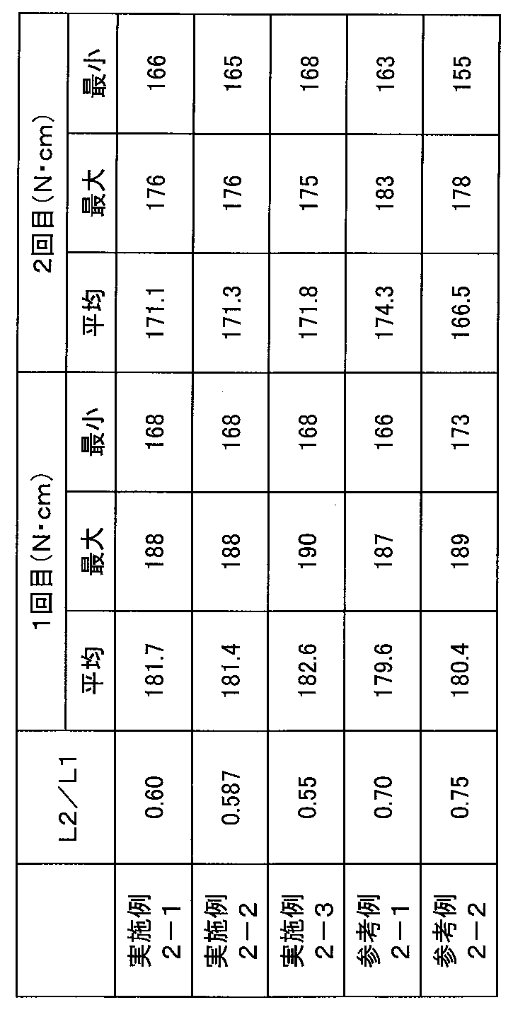
測定結果より、実施例2-1~2-3は、参考例2-1及び2-2と比較して、初回にオーバーランの発生するトルクが大きいこと、すなわち、オーバーランが発生しにくいことが確認できた。また、いずれの場合にも、2回目のオーバーランが発生するトルクが低下する傾向が見られるが、実施例2-1~2-3は、参考例2-2と比較してその低下量が少なく、また、トルクの値は参考例2-1、2-2と同程度であり、参考例2-1、2-2と比べてオーバーランが発生しやすくなることがないことが確認できた。
(オーバーラン発生時の液漏れ評価)
実施例2-1~2-3、参考例2-1及び2-2を取り付けた包装容器を用いて、オーバーラン発生後の内容液の漏れ性能についての評価を行った。実施例2-1~2-3、参考例2-1及び2-2に係る口栓本体の隔壁を取り除き、包装容器に水1.8リットルを充填した後、それぞれの側壁に螺合したキャップにオーバーランが発生するまで回転荷重を加えた。オーバーランが発生した時点で荷重を加えるのをやめ、そのままで包装容器の注出口栓及びキャップを下に向けて、水漏れの有無を確認した。その後、キャップの螺合を緩めた後、今度はオーバーランが発生しない回転荷重を加えてキャップを螺合し、キャップを螺合した状態のままで包装容器の注出口栓及びキャップを下に向けて、水漏れの有無を確認した。評価結果を、表3に示す。
実施例2-1~2-3、参考例2-1及び2-2を取り付けた包装容器を用いて、オーバーラン発生後の内容液の漏れ性能についての評価を行った。実施例2-1~2-3、参考例2-1及び2-2に係る口栓本体の隔壁を取り除き、包装容器に水1.8リットルを充填した後、それぞれの側壁に螺合したキャップにオーバーランが発生するまで回転荷重を加えた。オーバーランが発生した時点で荷重を加えるのをやめ、そのままで包装容器の注出口栓及びキャップを下に向けて、水漏れの有無を確認した。その後、キャップの螺合を緩めた後、今度はオーバーランが発生しない回転荷重を加えてキャップを螺合し、キャップを螺合した状態のままで包装容器の注出口栓及びキャップを下に向けて、水漏れの有無を確認した。評価結果を、表3に示す。
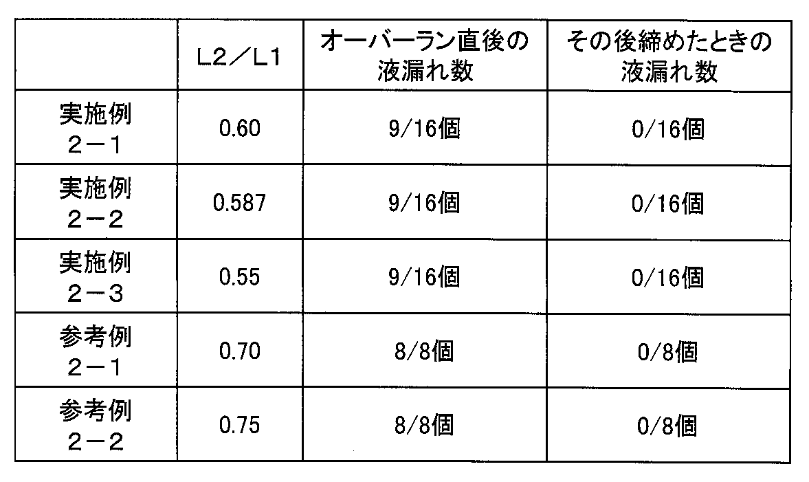
評価結果より、参考例2-1及び2-2では、オーバーランが発生した状態では、全ケースで水漏れを防ぐことができなかったのに対して、実施例2-1~2-3では、オーバーランが発生した状態でも側壁の変形が小さく、16ケース中7ケースは水漏れを防ぐことができており、密封性が向上していることが確認できた。また、キャップを締め直すことにより、実施例2-1~2-3、参考例2-1、2-2ともに全ケースで水漏れを防ぐことができ、実施例が従来品に比べてオーバーラン後の締め直しによって同程度の密封性を維持できることも確認できた。
<評価3>
実施例3-1~3-9は、図5の(a)に断面図を示す上述の実施形態に係る注出口栓1であり、上述のL3、L4はL3<L4である。参考例3-1、3-2は、実施形態に係る注出口栓において、L3<L4とする代わりにL3>L4としたものである。これらのうち、実施例3-1、3-2、3-4、3-5、3-7、3-8および参考例3-1、3-2は、上述のD1、D2をD1<D2とし、実施例3-3、3-6、3-9は、D1>D2とした。また、実施例3-1、3-4、3-7および参考例3-1は、ガイド部が下端に向かって外径が大きくなる部分を設け、実施例3-2、3-3、3-5、3-6、3-8、3-9および参考例3-2は外径が大きくなる部分を設けなかった。
実施例3-1~3-9は、図5の(a)に断面図を示す上述の実施形態に係る注出口栓1であり、上述のL3、L4はL3<L4である。参考例3-1、3-2は、実施形態に係る注出口栓において、L3<L4とする代わりにL3>L4としたものである。これらのうち、実施例3-1、3-2、3-4、3-5、3-7、3-8および参考例3-1、3-2は、上述のD1、D2をD1<D2とし、実施例3-3、3-6、3-9は、D1>D2とした。また、実施例3-1、3-4、3-7および参考例3-1は、ガイド部が下端に向かって外径が大きくなる部分を設け、実施例3-2、3-3、3-5、3-6、3-8、3-9および参考例3-2は外径が大きくなる部分を設けなかった。
各注出口栓において、キャップの口栓本体への挿入および螺合が、引っかかり等がなくスムーズに進行するかどうかを評価した。評価は、スムーズであった回数が、10試行中10回であった場合に++(優)、7回以上であった場合に+(良)、6回以下であった場合に不可(-)とした。結果を表4に示す。
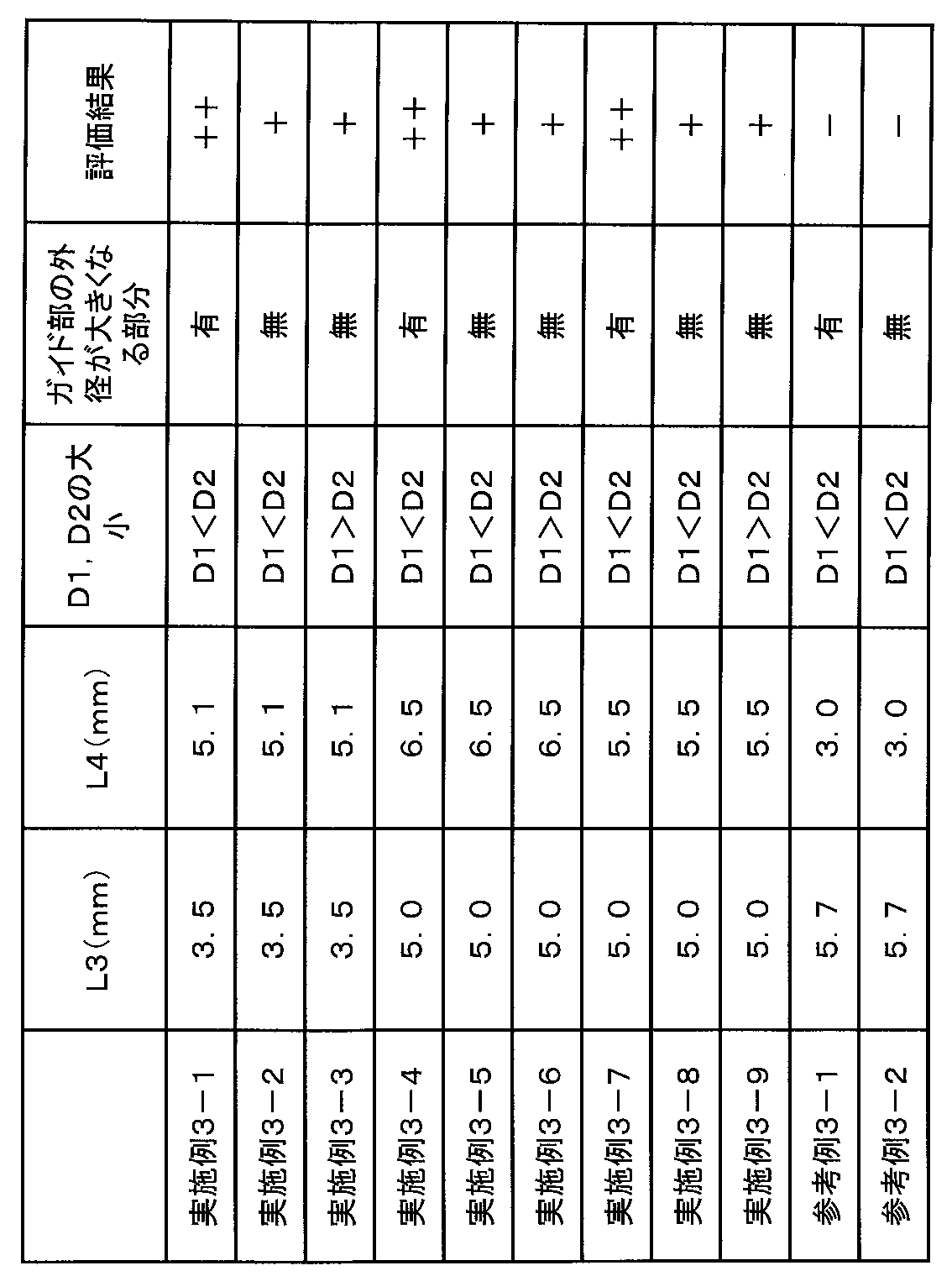
表4に示すように、L3<L4とした場合、評価結果は、++または+であり、L3>L4とした場合、評価結果は-であった。そのため、本発明の効果が確認できた。また、L3<L4とした場合は、D1<D2とし、かつ、ガイド部が下端に向かって外径が大きくなる部分を設けると、評価結果は++となり、より好ましいことが確認できた。
本発明は、紙製包装容器、ペットボトル、ビン、フレキシブル包装容器等の各種包装容器の口栓本体に用いることができる。
1 口栓本体
11 側壁
12 外ネジ
13 第1の外径部
103 プルリング
104 隔壁
108 リブ
109 天面
113 ガイド部
119 突出部
13 第1の外径部
14 第2の外径部
141 ハーフカット
15 突起部
16 フランジ部
17 外周面
18 肉盗み部
19 内周面
2 キャップ
21 側壁
22 内ネジ
23 内周面
24 天板
25 インナーリング
26 肉厚部
27 接触面
28 当接部
3 注出口栓
4 容器本体
5 包装容器
11 側壁
12 外ネジ
13 第1の外径部
103 プルリング
104 隔壁
108 リブ
109 天面
113 ガイド部
119 突出部
13 第1の外径部
14 第2の外径部
141 ハーフカット
15 突起部
16 フランジ部
17 外周面
18 肉盗み部
19 内周面
2 キャップ
21 側壁
22 内ネジ
23 内周面
24 天板
25 インナーリング
26 肉厚部
27 接触面
28 当接部
3 注出口栓
4 容器本体
5 包装容器
Claims (19)
- 円筒状の側壁を有する口栓本体と、
前記側壁の一端である上端側から装着されるキャップとを備え、
前記側壁の上端縁には、前記側壁の外方に突出する突起部が形成され、
前記側壁の上端の天面は、前記キャップを前記側壁に装着させた状態において、前記キャップ内方の所定の接触面に全周にわたって面接触する、注出口栓。 - 円筒状の側壁を有する口栓本体と、
前記側壁の一端である上端側から装着されるキャップとを備え、
前記側壁の上端縁には、前記側壁の外方に突出する突起部が形成され、
前記側壁の上面は、前記キャップを前記側壁に装着させた状態において、前記キャップ内方の所定の接触面に全周にわたって接触する、注出口栓。 - 前記キャップを前記側壁に装着させた状態において、
前記側壁は、弾性変形をして、上端の天面が一定の接触圧で前記キャップの接触面に面接触する、請求項1または2に記載の注出口栓。 - 前記キャップの材質の剛性は、前記側壁の材質の剛性よりも高い、請求項1~3のいずれかに記載の注出口栓。
- 前記キャップは、前記側壁の外周面に形成された外ネジ及び前記キャップの内周面に形成された内ネジが螺合することにより前記側壁に装着される、請求項1~4のいずれかに記載の注出口栓。
- 前記口栓本体の側壁の下端には、前記口栓本体の側壁の下端縁から外方に延伸して設けられた円盤状のフランジ部が形成され、
前記外ネジは、螺合軸方向に沿って、前記口栓本体の側壁の前記フランジ部との接続位置から、当該接続位置と上端縁との距離の3分の1以上3分の2以下の距離までの範囲に形成されている、請求項5に記載の、注出口栓。 - 前記キャップの材質の剛性は、前記口栓本体の材質の剛性よりも高い、請求項6に記載の注出口栓。
- 前記キャップの材質は、ポリプロピレン樹脂又は高密度ポリエチレン樹脂であり、
前記口栓本体の材質は、低密度ポリエチレン樹脂である、請求項6または7に記載の注出口栓。 - 前記キャップは、前記口栓本体の側壁と螺着した状態において、前記口栓本体の側壁の内周面に嵌合して、前記口栓本体の側壁を密封するインナーリングを有し、
前記口栓本体の側壁の上端部分は、前記キャップが前記口栓本体の側壁と螺着した状態において、前記インナーリングと前記キャップの側壁との間において、全周にわたって前記キャップに面接触する、請求項6~8のいずれかに記載の注出口栓。 - 前記口栓本体の側壁および前記キャップの側壁の少なくとも一方は、上端から下端に向かって径が広がるテーパが形成されている、請求項6~9のいずれかに記載の注出口栓。
- 前記側壁の外周面は、前記外ネジが形成された外ネジ部と、前記外ネジ部より上端側の領域である、前記外ネジが形成されていないガイド部とを有し、
螺合軸方向に沿った、前記内ネジ部の上端である形成開始位置と下端である形成終了位置との間の距離は、前記側壁の上端縁から前記外ネジ部の上端側の形成開始位置までの距離であるガイド部長さより小さい、請求項5に記載の注出口栓。 - 前記ガイド部は、上端縁の全周に外周方向に向かって突出する突起部が形成され、前記突起部より下端側に前記外ネジ部に向かって外径が大きくなる部分を有する、請求項11に記載の注出口栓。
- 前記キャップを前記側壁に螺合軸に沿って嵌合させた状態において、前記キャップの内周面と前記側壁の前記外ネジ部のネジ山頂部との間の距離より、前記キャップの前記内ネジ部のネジ山頂部と前記ガイド部の外周面との間の距離より大きい、請求項11または12に記載の注出口栓。
- 前記側壁の内部を閉塞し、外周部にハーフカットが形成された隔壁と、
前記側壁の下端縁から外方に延伸して設けられた円盤状のフランジ部と、
前記フランジ部の前記側壁とは反対側の面に、前記側壁と同心円状に設けられた溝状の肉盗み部と、
前記肉盗み部の内面に設けられた複数のリブとをさらに備え、
前記複数のリブのそれぞれは、前記肉盗み部の周方向に沿って、隣接するリブとの間隔が0.5mm以上5.0mm以下である、請求項1に記載の注出口栓。 - 前記複数のリブのそれぞれは、前記肉盗み部の周方向に沿って、長さが0.3mm以上1.5mm以下である、請求項14に記載の注出口栓。
- 前記複数のリブのそれぞれは、前記肉盗み部の周方向に沿って、長さが0.5mm以上である、請求項15に記載の注出口栓。
- 前記側壁の前記フランジ部より上端側には、外方に突出する少なくとも3個の突出部が円周等分に形成されている、請求項14~16のいずれかに記載の注出口栓。
- 前記外ネジ及び前記内ネジは、多条ネジである、請求項5~13のいずれかに記載の注出口栓。
- 容器本体と、
前記容器本体に取り付けられた請求項1~18のいずれかに記載の注出口栓とを含む、包装容器。
Priority Applications (4)
| Application Number | Priority Date | Filing Date | Title |
|---|---|---|---|
| US15/328,988 US10308402B2 (en) | 2014-07-30 | 2015-07-30 | Spout stopper and packaging container |
| CN201580040366.4A CN106573706B (zh) | 2014-07-30 | 2015-07-30 | 排出口栓以及包装容器 |
| KR1020177002669A KR102482736B1 (ko) | 2014-07-30 | 2015-07-30 | 주출구 마개 및 포장 용기 |
| SG11201700559UA SG11201700559UA (en) | 2014-07-30 | 2015-07-30 | Spout stopper and packaging container |
Applications Claiming Priority (16)
| Application Number | Priority Date | Filing Date | Title |
|---|---|---|---|
| JP2014155136 | 2014-07-30 | ||
| JP2014-155137 | 2014-07-30 | ||
| JP2014155137 | 2014-07-30 | ||
| JP2014-155136 | 2014-07-30 | ||
| JP2014-169413 | 2014-08-22 | ||
| JP2014169413 | 2014-08-22 | ||
| JP2014201214 | 2014-09-30 | ||
| JP2014-201214 | 2014-09-30 | ||
| JP2015145235A JP6278931B2 (ja) | 2014-08-22 | 2015-07-22 | 注出口栓及び包装容器 |
| JP2015-145236 | 2015-07-22 | ||
| JP2015145234A JP6226921B2 (ja) | 2014-07-30 | 2015-07-22 | 注出口栓及び包装容器 |
| JP2015-145235 | 2015-07-22 | ||
| JP2015145233A JP2016033057A (ja) | 2014-07-30 | 2015-07-22 | 注出口栓及び包装容器 |
| JP2015145236A JP2016069083A (ja) | 2014-09-30 | 2015-07-22 | 注出口栓及び包装容器 |
| JP2015-145234 | 2015-07-22 | ||
| JP2015-145233 | 2015-07-22 |
Publications (1)
| Publication Number | Publication Date |
|---|---|
| WO2016017178A1 true WO2016017178A1 (ja) | 2016-02-04 |
Family
ID=55217087
Family Applications (1)
| Application Number | Title | Priority Date | Filing Date |
|---|---|---|---|
| PCT/JP2015/003851 Ceased WO2016017178A1 (ja) | 2014-07-30 | 2015-07-30 | 注出口栓及び包装容器 |
Country Status (1)
| Country | Link |
|---|---|
| WO (1) | WO2016017178A1 (ja) |
Cited By (2)
| Publication number | Priority date | Publication date | Assignee | Title |
|---|---|---|---|---|
| EP3666678A4 (en) * | 2017-08-10 | 2020-08-19 | Toppan Printing Co., Ltd. | SPOUT CAP AND PACKAGING CONTAINER WITH A SPOUT CAP |
| US11414242B2 (en) | 2017-08-10 | 2022-08-16 | Toppan Printing Co., Ltd. | Spout assembly and packaging container having the spout assembly |
Citations (11)
| Publication number | Priority date | Publication date | Assignee | Title |
|---|---|---|---|---|
| JPS5041950U (ja) * | 1973-08-09 | 1975-04-28 | ||
| US5388731A (en) * | 1993-05-04 | 1995-02-14 | Continental Plastics, Inc. | Cap and dispensing fitment combination wherein the cap has retaining means engaging the fitment |
| JPH10157731A (ja) * | 1996-11-26 | 1998-06-16 | Dainippon Printing Co Ltd | 液体紙容器の注出口組合わせ体 |
| JPH10167297A (ja) * | 1996-12-11 | 1998-06-23 | Banyu Pharmaceut Co Ltd | 中栓、キャップ並びに中栓とキャップの組合せ体 |
| JPH11171233A (ja) * | 1997-12-17 | 1999-06-29 | Dainippon Printing Co Ltd | 液体容器用注出口 |
| JP2004067101A (ja) * | 2002-08-01 | 2004-03-04 | Toppan Printing Co Ltd | プルリング付キャップ |
| JP2004149164A (ja) * | 2002-10-31 | 2004-05-27 | Dainippon Printing Co Ltd | キャップ |
| JP2011105383A (ja) * | 2009-11-20 | 2011-06-02 | Toppan Printing Co Ltd | 注出口栓および包装容器 |
| WO2011078085A1 (ja) * | 2009-12-22 | 2011-06-30 | 日本クラウンコルク株式会社 | 合成樹脂製注出口栓 |
| JP2012245997A (ja) * | 2011-05-26 | 2012-12-13 | Cemedine Co Ltd | キャップ付チューブ容器及びその製造方法 |
| JP2014019447A (ja) * | 2012-07-12 | 2014-02-03 | Toppan Printing Co Ltd | 口栓 |
-
2015
- 2015-07-30 WO PCT/JP2015/003851 patent/WO2016017178A1/ja not_active Ceased
Patent Citations (11)
| Publication number | Priority date | Publication date | Assignee | Title |
|---|---|---|---|---|
| JPS5041950U (ja) * | 1973-08-09 | 1975-04-28 | ||
| US5388731A (en) * | 1993-05-04 | 1995-02-14 | Continental Plastics, Inc. | Cap and dispensing fitment combination wherein the cap has retaining means engaging the fitment |
| JPH10157731A (ja) * | 1996-11-26 | 1998-06-16 | Dainippon Printing Co Ltd | 液体紙容器の注出口組合わせ体 |
| JPH10167297A (ja) * | 1996-12-11 | 1998-06-23 | Banyu Pharmaceut Co Ltd | 中栓、キャップ並びに中栓とキャップの組合せ体 |
| JPH11171233A (ja) * | 1997-12-17 | 1999-06-29 | Dainippon Printing Co Ltd | 液体容器用注出口 |
| JP2004067101A (ja) * | 2002-08-01 | 2004-03-04 | Toppan Printing Co Ltd | プルリング付キャップ |
| JP2004149164A (ja) * | 2002-10-31 | 2004-05-27 | Dainippon Printing Co Ltd | キャップ |
| JP2011105383A (ja) * | 2009-11-20 | 2011-06-02 | Toppan Printing Co Ltd | 注出口栓および包装容器 |
| WO2011078085A1 (ja) * | 2009-12-22 | 2011-06-30 | 日本クラウンコルク株式会社 | 合成樹脂製注出口栓 |
| JP2012245997A (ja) * | 2011-05-26 | 2012-12-13 | Cemedine Co Ltd | キャップ付チューブ容器及びその製造方法 |
| JP2014019447A (ja) * | 2012-07-12 | 2014-02-03 | Toppan Printing Co Ltd | 口栓 |
Cited By (2)
| Publication number | Priority date | Publication date | Assignee | Title |
|---|---|---|---|---|
| EP3666678A4 (en) * | 2017-08-10 | 2020-08-19 | Toppan Printing Co., Ltd. | SPOUT CAP AND PACKAGING CONTAINER WITH A SPOUT CAP |
| US11414242B2 (en) | 2017-08-10 | 2022-08-16 | Toppan Printing Co., Ltd. | Spout assembly and packaging container having the spout assembly |
Similar Documents
| Publication | Publication Date | Title |
|---|---|---|
| KR102482736B1 (ko) | 주출구 마개 및 포장 용기 | |
| RU2585568C2 (ru) | Винтовой укупорочный колпачок | |
| JP6484308B2 (ja) | 缶蓋 | |
| US9718587B2 (en) | Synthetic resin cap, synthetic resin cap liner, closing device, and beverage-contained closing device | |
| WO2019031608A1 (ja) | 注出口栓及び注出口栓を備える包装容器 | |
| JP6278931B2 (ja) | 注出口栓及び包装容器 | |
| RU2294870C2 (ru) | Затвор в виде пробки | |
| JP2005516861A (ja) | 容器および容器の変形を隔離することによりそこからの漏れを防止する方法 | |
| KR20160064169A (ko) | 계측 뚜껑 | |
| JP2016069083A (ja) | 注出口栓及び包装容器 | |
| JP7259228B2 (ja) | 注出口栓及び注出口栓を備える包装容器 | |
| CN102834330A (zh) | 用于带螺纹盖子的结合唇肩密封件 | |
| US2025852A (en) | Container | |
| JP5468278B2 (ja) | 缶蓋 | |
| JP7354582B2 (ja) | 注出口栓およびこれを備える包装容器 | |
| JP4711857B2 (ja) | 紙パック用のスパウト | |
| JP7413656B2 (ja) | 注出口組立体、注出口付き容器、注出口及びキャップ | |
| JP2017197253A (ja) | 注出口栓及び包装容器 | |
| KR20040089113A (ko) | 폐쇄 마개 | |
| JP7164145B2 (ja) | 打栓式キャップ、及び、注出口栓 | |
| WO2015181978A1 (ja) | 容器口部 | |
| JP2020079095A (ja) | 注出口栓 | |
| JP6226921B2 (ja) | 注出口栓及び包装容器 | |
| JP7456140B2 (ja) | 注出口栓およびこれを備える包装容器 | |
| JP2019167139A (ja) | 樹脂製キャップ及びこの樹脂製キャップと容器口部の組み合わせ |
Legal Events
| Date | Code | Title | Description |
|---|---|---|---|
| 121 | Ep: the epo has been informed by wipo that ep was designated in this application |
Ref document number: 15827619 Country of ref document: EP Kind code of ref document: A1 |
|
| NENP | Non-entry into the national phase |
Ref country code: DE |
|
| ENP | Entry into the national phase |
Ref document number: 20177002669 Country of ref document: KR Kind code of ref document: A |
|
| 122 | Ep: pct application non-entry in european phase |
Ref document number: 15827619 Country of ref document: EP Kind code of ref document: A1 |