WO2016013334A1 - 磁性体薄膜形成用スパッタリングターゲット - Google Patents
磁性体薄膜形成用スパッタリングターゲット Download PDFInfo
- Publication number
- WO2016013334A1 WO2016013334A1 PCT/JP2015/067539 JP2015067539W WO2016013334A1 WO 2016013334 A1 WO2016013334 A1 WO 2016013334A1 JP 2015067539 W JP2015067539 W JP 2015067539W WO 2016013334 A1 WO2016013334 A1 WO 2016013334A1
- Authority
- WO
- WIPO (PCT)
- Prior art keywords
- powder
- sputtering target
- oxide
- particles
- particle
- Prior art date
- Legal status (The legal status is an assumption and is not a legal conclusion. Google has not performed a legal analysis and makes no representation as to the accuracy of the status listed.)
- Ceased
Links
Images



Classifications
-
- G—PHYSICS
- G11—INFORMATION STORAGE
- G11B—INFORMATION STORAGE BASED ON RELATIVE MOVEMENT BETWEEN RECORD CARRIER AND TRANSDUCER
- G11B5/00—Recording by magnetisation or demagnetisation of a record carrier; Reproducing by magnetic means; Record carriers therefor
- G11B5/62—Record carriers characterised by the selection of the material
- G11B5/64—Record carriers characterised by the selection of the material comprising only the magnetic material without bonding agent
- G11B5/65—Record carriers characterised by the selection of the material comprising only the magnetic material without bonding agent characterised by its composition
- G11B5/658—Record carriers characterised by the selection of the material comprising only the magnetic material without bonding agent characterised by its composition containing oxygen, e.g. molecular oxygen or magnetic oxide
-
- C—CHEMISTRY; METALLURGY
- C22—METALLURGY; FERROUS OR NON-FERROUS ALLOYS; TREATMENT OF ALLOYS OR NON-FERROUS METALS
- C22C—ALLOYS
- C22C19/00—Alloys based on nickel or cobalt
- C22C19/07—Alloys based on nickel or cobalt based on cobalt
-
- C—CHEMISTRY; METALLURGY
- C23—COATING METALLIC MATERIAL; COATING MATERIAL WITH METALLIC MATERIAL; CHEMICAL SURFACE TREATMENT; DIFFUSION TREATMENT OF METALLIC MATERIAL; COATING BY VACUUM EVAPORATION, BY SPUTTERING, BY ION IMPLANTATION OR BY CHEMICAL VAPOUR DEPOSITION, IN GENERAL; INHIBITING CORROSION OF METALLIC MATERIAL OR INCRUSTATION IN GENERAL
- C23C—COATING METALLIC MATERIAL; COATING MATERIAL WITH METALLIC MATERIAL; SURFACE TREATMENT OF METALLIC MATERIAL BY DIFFUSION INTO THE SURFACE, BY CHEMICAL CONVERSION OR SUBSTITUTION; COATING BY VACUUM EVAPORATION, BY SPUTTERING, BY ION IMPLANTATION OR BY CHEMICAL VAPOUR DEPOSITION, IN GENERAL
- C23C14/00—Coating by vacuum evaporation, by sputtering or by ion implantation of the coating forming material
- C23C14/22—Coating by vacuum evaporation, by sputtering or by ion implantation of the coating forming material characterised by the process of coating
- C23C14/34—Sputtering
-
- G—PHYSICS
- G11—INFORMATION STORAGE
- G11B—INFORMATION STORAGE BASED ON RELATIVE MOVEMENT BETWEEN RECORD CARRIER AND TRANSDUCER
- G11B5/00—Recording by magnetisation or demagnetisation of a record carrier; Reproducing by magnetic means; Record carriers therefor
- G11B5/84—Processes or apparatus specially adapted for manufacturing record carriers
Definitions
- the present invention relates to a magnetic material sputtering target used to form a magnetic thin film of a magnetic recording medium, in particular, a granular film in a magnetic recording medium of a hard disk adopting a perpendicular magnetic recording method, and causes the generation of particles during sputtering.
- the present invention relates to a non-magnetic material particle-dispersed magnetic material sputtering target containing Co or Fe as a main component, which can suppress abnormal discharge of the non-magnetic material.
- a material based on Co or Fe which is a ferromagnetic metal, is used for a recording layer of a hard disk adopting a perpendicular magnetic recording system.
- Co—Cr-based, Co—Pt, Co—Cr—Pt-based, and Fe—Pt-based alloys composed mainly of ferromagnetic metals and non-magnetic inorganic materials are often used. Yes.
- the magnetic thin film of such magnetic recording media, such as a hard disk is often produced by sputtering a sputtering target containing the above material as a component because of high productivity.
- a melting method or a powder metallurgy method can be considered as a method for producing a sputtering target for a magnetic recording medium. Which method is used depends on the required characteristics, but it cannot be unequivocally stated, but it is used for the recording layer of hard disks of the perpendicular magnetic recording system, an alloy mainly composed of a ferromagnetic metal and a non-magnetic inorganic substance.
- Sputtering targets made of particles are generally produced by powder metallurgy. This is because the inorganic particles need to be uniformly dispersed in the alloy substrate, and thus it is difficult to produce by the melting method.
- Patent Document 1 As a powder metallurgy method, for example, in Patent Document 1, mixed powder obtained by mixing Co powder, Cr powder, TiO 2 powder, and SiO 2 powder and Co spherical powder are mixed by a planetary motion mixer, and this mixing is performed. Patent Document 2 proposes a method of obtaining a sputtering target for a magnetic recording medium by forming powder by hot pressing. Patent Document 2 discloses a sputtering target for forming a magnetic recording medium thin film by mixing Co—Cr binary alloy powder, Pt powder, and SiO 2 powder and hot-pressing the obtained mixed powder. A method has been proposed.
- Patent Document 3 proposes a sputtering target composed of a matrix phase of Co and Pt and a metal oxide phase having an average particle size of 0.05 ⁇ m or more and less than 7.0 ⁇ m, which suppresses the growth of crystal grains and has a low Proposals have been made to increase the film formation efficiency by obtaining a magnetic permeability and high density target. Further, in Patent Document 4, the average particle diameter of the particles formed by the oxide phase is set to 3 ⁇ m or less, and in Patent Document 5, silica particles or titania particles are sputtered in a cross section perpendicular to the main surface of the sputtering target. It is described that 2 ⁇ Dp / Dn is satisfied, where Dn is a particle size in a direction perpendicular to the main surface of the target and Dp is a particle size in a direction parallel to the main surface.
- the average particle diameter of the oxide particles present in the target is 1.5 ⁇ m or less, and the maximum value of the distance between any two points on the outer periphery of the oxide particles is the maximum diameter,
- the minimum value of the distance between two lines when the same particle is sandwiched between two parallel lines is set as the minimum diameter, oxide particles having a difference between the maximum diameter and the minimum diameter of 0.4 ⁇ m or less are observed on the target. It is described that it occupies 60% or more on the surface. However, none of these conditions is sufficient and the present situation is that further improvement is required.
- a non-magnetic material such as an oxide is an insulator, which causes abnormal discharge. Due to this abnormal discharge, generation of particles during sputtering becomes a problem. In particular, when a coarse non-magnetic material phase is formed in the structure of the sputtering target, abnormal discharge occurs from that point, and the particles are remarkably increased.
- the inventors of the present invention have found that in a sputtering target containing an oxide phase as non-magnetic material particles, the oxide phase is formed in the form of a material having a high melting point. It has been found that by making it exist in the inside, the coarsening of the oxide phase can be prevented, an abnormal discharge due to a nonmagnetic material during sputtering does not occur, and a target with less generation of particles can be obtained.
- the average number of oxide particles in which the particle area S of the oxide is 10 ⁇ m 2 or more and the ratio (S / L) of the particle area S to the circumference L of the particles is 0.35 or more is 0.
- the non-magnetic material particle dispersion type magnetic material sputtering target of the present invention thus adjusted does not cause abnormal discharge due to the non-magnetic material during sputtering, and a target with less generation of particles can be obtained. Thereby, it has the outstanding effect that the cost improvement effect by a yield improvement can be acquired.
- FIG. 1 is a diagram (photograph) showing a cross-sectional structure of a sputtering target of Example 1.
- FIG. It is a figure (photograph) which shows the sputtering target cross-sectional structure of the comparative example 1.
- FIG. It is a figure (photograph) which shows the sputtering target cross-sectional structure of the comparative example 2.
- the sputtering target of the present invention has a structure in which oxide particles are dispersed as a nonmagnetic material in an alloy containing Co or Fe as a main component.
- the alloy containing Co or Fe as a main component include ferromagnetic alloys such as a Co—Cr alloy, a Co—Pt alloy, a Co—Cr—Pt alloy, and an Fe—Pt alloy.
- ferromagnetic alloys such as a Co—Cr alloy, a Co—Pt alloy, a Co—Cr—Pt alloy, and an Fe—Pt alloy.
- the oxide particles dispersed as a nonmagnetic material contain an oxide containing at least Ti and B.
- B 2 O 3 boron oxide
- boron oxide has been used as a raw material powder of an oxide containing B (boron) as a constituent component, but boron oxide has a melting point of 577 ° C., which is lower than the sintering temperature.
- the oxide particles There was a tendency for the oxide particles to be coarsened by melting and aggregating during the setting. Such coarse particles are a cause of generation of particles during sputtering. Therefore, the present invention is characterized in that elution during sintering is prevented by using TiBO 3 having a high melting point for part or all of the raw material powder of the oxide containing B as a constituent component. .
- the present invention can thus suppress the coarsening of the oxide particles.
- the particle area S is 10 ⁇ m 2 or more, and the particle area S and the length of the circumference of the particle
- the number of oxide particles having a ratio (S / L) to the thickness L of 0.35 or more can be 0.0015 particles / ⁇ m 2 or less.
- the number of oxide particles having a ratio (S / L) of the particle area S to the peripheral length L of the particle is 0.35 or more is 0.007 particles / ⁇ m 2 or less.
- the present invention is particularly effective when B (boron) and an oxide that is more thermodynamically unstable than B 2 O 3 are contained.
- B and an oxide that is more thermodynamically unstable than B 2 O 3 coexist, boron oxide is easily generated during sintering, and the oxide particles become coarse.
- An oxide that is more thermodynamically unstable than B 2 O 3 means a metal oxide whose absolute value of standard formation energy ( ⁇ G) of the metal oxide is smaller than that of B 2 O 3 , for example, Examples include CoO, Co 3 O 4 , FeO, Fe 2 O 3 , CuO, and Cu 2 O.
- oxides including Ti and B oxides exist as single oxides and / or composite oxides.
- oxide particles composed of these oxides also have an oxidation in which the particle area S is 10 ⁇ m 2 or more and the ratio (S / L) between the particle area S and the circumference L of the particles is 0.35 or more. The number of physical particles satisfies 0.0015 / ⁇ m 2 or less.
- known materials such as carbides and nitrides can be added as nonmagnetic materials.
- the nonmagnetic material containing an oxide is preferably 10% to 50% by volume. If it is less than 10%, the effect of blocking the magnetic interaction between the magnetic particles is diminished, and if it exceeds 50%, the dispersibility of the nonmagnetic particles is deteriorated and the number of particles tends to increase.
- the measurement of the size and number of oxide particles is performed by polishing the surface of the sputtering target until the oxide particles can be identified, observing any 10 locations of the sputtering target with a visual field of 70 ⁇ m ⁇ 100 ⁇ m, and The number of so-called coarse oxide particles having a particle area S of 10 ⁇ m 2 or more and a ratio (S / L) of the particle area S to the peripheral length L of the particles of 0.35 or more is counted. Then, the number of oxide particles per unit area is calculated by dividing by the total observation area.
- B constituting the oxide is preferably contained in an amount of 0.5 at% to 15 at% with respect to the composition of the sputtering target. If B is less than 0.5 at%, it is difficult to obtain desired magnetic characteristics, and if it exceeds 15 at%, B 2 O 3 is easily formed and coarsening proceeds, which is not preferable. Furthermore, Ti constituting the oxide is preferably contained in an amount of 0.5 at% to 15 at% with respect to the composition of the sputtering target. Formation of a complex oxide of less than 0.5 at% is not sufficient, and if it exceeds 15 at%, it is difficult to control the magnetic properties, which is not preferable.
- the sputtering target of the present invention can be produced by a powder metallurgy method.
- metal powder not only a single element metal powder but also an alloy powder can be used.
- the particle size is 0.1 to 10 ⁇ m, more uniform mixing is possible, and segregation and coarse crystallization of the sintered target can be prevented.
- the metal powder is larger than 10 ⁇ m, the oxide phase may not be finely dispersed.
- the influence of the oxidation of the metal powder may be a problem.
- What is important in the present invention is to use a complex oxide of B having a relatively high melting point such as TiBO 3 as a raw material powder instead of B 2 O 3 as an oxide containing B as a constituent component.
- TiBO 3 powder for example, Ti 2 O 3 powder and B 2 O 3 powder mixed, synthesized, and pulverized can be used.
- the average particle diameter of the oxide powder is desirably in the range of 0.2 to 5 ⁇ m. When the particle size is 0.2 to 5 ⁇ m, there is an advantage that uniform mixing with the metal powder is facilitated.
- the average particle diameter of the oxide powder is larger than 5 ⁇ m, a coarse oxide phase may be formed after sintering, and when smaller than 0.2 ⁇ m, the oxide powder may be aggregated. is there.
- the above raw material powder is weighed so as to have a desired composition, and mixed by pulverization using a known method such as a ball mill. In order to shorten the mixing time and increase the productivity, it is preferable to use a high energy ball mill.
- the mixed powder thus obtained is molded and sintered in a vacuum atmosphere or an inert gas atmosphere by a hot press method.
- various pressure sintering methods such as a plasma discharge sintering method can be used.
- the hot isostatic pressing is effective for improving the density of the sintered body.
- the sintering temperature depends on the composition, it is often in the range of 700 ° C. to 1100 ° C.
- the obtained sintered body is processed into a desired shape with a lathe, and the surface is cut and polished, whereby the sputtering target of the present invention can be produced.
- the sputtering target manufactured in this manner can significantly reduce the amount of particles generated during sputtering, and thus has an excellent effect of improving the yield during film formation.
- Co powder and Pt powder were prepared as metal powders, and TiBO 3 powder, TiO 2 powder, SiO 2 powder, and CoO powder were prepared as non-magnetic material powders.
- TiBO 3 powder pre-mixing the Ti 2 O 3 powder and B 2 O 3 powder, synthesized, it was used after grinding. Then, 2000 g of these powders were weighed at the following composition ratio.
- the weighed powder was enclosed in a ball mill pot with a capacity of 10 liters together with a tungsten alloy ball as a grinding medium, and rotated and mixed for 120 hours.
- the mixed powder thus obtained was filled in a carbon mold and hot-pressed in a vacuum atmosphere at a temperature of 980 ° C., a holding time of 2 hours, and a pressure of 30 MPa to obtain a sintered body. Further, this was cut with a lathe to obtain a disk-shaped sputtering target having a diameter of 164 mm and a thickness of 4 mm.
- the surface of the sputtering target was polished and the structure was observed with a laser microscope.
- the regions that appear whitish are the Co and Pt metal phases
- the regions that appear whitish are the oxide phases.
- Observation at an arbitrary 10 locations on the surface of the sputtering target with a visual field of 71 ⁇ m ⁇ 94 ⁇ m revealed that the particle area S was 10 ⁇ m 2 or more, and the ratio (S / L) of the particle area S to the circumference L of the particle was 0.35.
- the average number of oxide particles as described above was 1.40. That is, the average number per unit area was 0.0002 / ⁇ m 2 .
- this target was attached to a DC magnetron sputtering apparatus, and sputtering was performed.
- the sputtering conditions were a sputtering power of 1.0 kW and an Ar gas pressure of 3.2 Pa, and sputtering was performed on a 4-inch diameter silicon substrate for 200 seconds.
- the number of particles adhering to the substrate was measured with a particle counter.
- the number of particles on the silicon substrate at this time was an extremely small level of 5 on average.
- Co powder and Pt powder were prepared as metal powders, and TiBO 3 powder, TiO 2 powder, SiO 2 powder, and CoO powder were prepared as non-magnetic material powders.
- TiBO 3 powder pre-mixing the Ti 2 O 3 powder and B 2 O 3 powder, synthesized, it was used after grinding. Then, 2000 g of these powders were weighed at the following composition ratio.
- the weighed powder was enclosed in a ball mill pot with a capacity of 10 liters together with a tungsten alloy ball as a grinding medium, and rotated and mixed for 120 hours.
- the mixed powder thus obtained was filled in a carbon mold and hot-pressed in a vacuum atmosphere at a temperature of 980 ° C., a holding time of 2 hours, and a pressure of 30 MPa to obtain a sintered body. Further, this was cut with a lathe to obtain a disk-shaped sputtering target having a diameter of 164 mm and a thickness of 4 mm.
- the surface of the sputtering target was polished and the structure was observed with a laser microscope.
- the regions that appear whitish are the Co and Pt metal phases, and the regions that appear whitish are the oxide phases.
- the particle area S is 10 ⁇ m 2 or more, and the ratio (S / L) between the particle area S and the length L around the particle is 0.35 or more.
- the average number per unit area was 0.0003 / ⁇ m 2 , indicating a good result.
- this target was attached to a DC magnetron sputtering apparatus, and sputtering was performed.
- the sputtering conditions were a sputtering power of 1.0 kW and an Ar gas pressure of 3.2 Pa, and sputtering was performed on a 4-inch diameter silicon substrate for 200 seconds.
- the number of particles adhering to the substrate was measured with a particle counter.
- the number of particles on the silicon substrate at this time was an extremely small level of 5 on average.
- the weighed powder was enclosed in a ball mill pot with a capacity of 10 liters together with a tungsten alloy ball as a grinding medium, and rotated and mixed for 120 hours.
- the mixed powder thus obtained was filled in a carbon mold and hot-pressed in a vacuum atmosphere at a temperature of 980 ° C., a holding time of 2 hours, and a pressure of 30 MPa to obtain a sintered body. Further, this was cut with a lathe to obtain a disk-shaped sputtering target having a diameter of 164 mm and a thickness of 4 mm.
- the surface of the sputtering target was polished and the structure was observed with a laser microscope.
- the regions that appear whitish are the Co and Pt metal phases, and the regions that appear whitish are the oxide phases.
- the particle area S is 10 ⁇ m 2 or more, and the ratio (S / L) between the particle area S and the length L around the particle is 0.35 or more.
- the average number per unit area increased to 0.0022 / ⁇ m 2 .
- sputtering was performed under the same conditions as in Example 1, and the number of particles adhering to the substrate was measured with a particle counter. At this time, the number of particles on the silicon substrate was at an extremely high level of 100 or more on average.
- the weighed powder was enclosed in a ball mill pot with a capacity of 10 liters together with a tungsten alloy ball as a grinding medium, and rotated and mixed for 120 hours.
- the mixed powder thus obtained was filled in a carbon mold and hot-pressed in a vacuum atmosphere at a temperature of 980 ° C., a holding time of 2 hours, and a pressure of 30 MPa to obtain a sintered body. Further, this was cut with a lathe to obtain a disk-shaped sputtering target having a diameter of 164 mm and a thickness of 4 mm.
- the surface of the sputtering target was polished and the structure was observed with a laser microscope.
- the regions that appear whitish are the Co and Pt metal phases, and the regions that appear whitish are the oxide phases.
- the particle area S is 10 ⁇ m 2 or more, and the ratio (S / L) between the particle area S and the length L around the particle is 0.35 or more.
- the average number per unit area increased to 0.0032 / ⁇ m 2 .
- sputtering was performed under the same conditions as in Example 1, and the number of particles adhering to the substrate was measured with a particle counter. At this time, the number of particles on the silicon substrate was at an extremely high level of 100 or more on average.
- Co powder and Co—B powder were prepared as metal powders, and TiBO 3 powder, TiO 2 powder and SiO 2 powder were prepared as non-magnetic material powders.
- TiBO 3 powder pre-mixing the Ti 2 O 3 powder and B 2 O 3 powder, synthesized, it was used after grinding. Then, 2000 g of these powders were weighed at the following composition ratio.
- the weighed powder was enclosed in a ball mill pot with a capacity of 10 liters together with a tungsten alloy ball as a grinding medium, and rotated and mixed for 120 hours.
- the mixed powder thus obtained was filled in a carbon mold and hot-pressed in a vacuum atmosphere at a temperature of 980 ° C., a holding time of 2 hours, and a pressure of 30 MPa to obtain a sintered body. Further, this was cut with a lathe to obtain a disk-shaped sputtering target having a diameter of 164 mm and a thickness of 4 mm.
- the surface of the sputtering target was polished and the structure was observed with a laser microscope.
- an oxide particle having a particle area S of 10 ⁇ m 2 or more and a ratio (S / L) between the particle area S and the length L around the particle is 0.35 or more
- the average number per unit area was 0.0002 / ⁇ m 2 , indicating a good result.
- sputtering was performed under the same conditions as in Example 1, and the number of particles adhering to the substrate was measured with a particle counter. The number of particles on the silicon substrate at this time was an extremely small level of 6 on average.
- Example 4 Fe powder, Fe—B powder, and Pt powder were prepared as metal powders, and TiBO 3 powder, TiO 2 powder, and MnO 2 powder were prepared as nonmagnetic material powders.
- TiBO 3 powder pre-mixing the Ti 2 O 3 powder and B 2 O 3 powder, synthesized, it was used after grinding. Then, 2000 g of these powders were weighed at the following composition ratio. Composition (at%): Fe-33.33Pt-3.33B-3.33Ti-4.17Mn-16.67O
- the weighed powder was enclosed in a ball mill pot with a capacity of 10 liters together with a steel ball ball as a grinding medium, and rotated and mixed for 120 hours.
- the mixed powder thus obtained was filled in a carbon mold and hot-pressed in a vacuum atmosphere at a temperature of 980 ° C., a holding time of 2 hours, and a pressure of 30 MPa to obtain a sintered body. Further, this was cut with a lathe to obtain a disk-shaped sputtering target having a diameter of 164 mm and a thickness of 4 mm.
- the surface of the sputtering target was polished and the structure was observed with a laser microscope.
- an oxide particle having a particle area S of 10 ⁇ m 2 or more and a ratio (S / L) between the particle area S and the length L around the particle is 0.35 or more
- the average number per unit area was 0.0006 / ⁇ m 2 , indicating a good result.
- sputtering was performed under the same conditions as in Example 1, and the number of particles adhering to the substrate was measured with a particle counter. The number of particles on the silicon substrate at this time was an extremely small level of 6 on average.
- the present invention can suppress abnormal discharge due to a nonmagnetic material during sputtering by suppressing aggregation (coarseness) of the oxide phase.
- the magnetic thin film of a magnetic recording medium particularly a hard disk, has an excellent effect of reducing the generation of particles during sputtering caused by abnormal discharge and obtaining a cost improvement effect by improving yield. It is useful as a ferromagnetic material sputtering target used for forming a drive recording layer.
Landscapes
- Chemical & Material Sciences (AREA)
- Organic Chemistry (AREA)
- Engineering & Computer Science (AREA)
- Materials Engineering (AREA)
- Mechanical Engineering (AREA)
- Metallurgy (AREA)
- Physics & Mathematics (AREA)
- Spectroscopy & Molecular Physics (AREA)
- Chemical Kinetics & Catalysis (AREA)
- Physical Vapour Deposition (AREA)
- Manufacturing Of Magnetic Record Carriers (AREA)
- Powder Metallurgy (AREA)
- Magnetic Record Carriers (AREA)
Abstract
本発明は、Co又はFeを含む合金と少なくともTi、Bを含む酸化物を含有するスパッタリングターゲットであって、該スパッタリングターゲットの組織において、酸化物の粒子面積Sが10μm2以上、かつ、粒子面積Sと粒子の周囲の長さLとの比(S/L)が0.35以上である酸化物粒子の平均個数が、0.0015個/μm2以下であることを特徴とするスパッタリングターゲット。スパッタリング時のパーティクル発生の原因となる非磁性材料に起因する異常放電を抑制することができる。
Description
本発明は、磁気記録媒体の磁性体薄膜、特に垂直磁気記録方式を採用したハードディスクの磁気記録媒体におけるグラニュラー膜の成膜に使用される磁性材スパッタリングターゲットに関し、スパッタリングの際にパーティクル発生の原因となる非磁性材の異常放電を抑制することができる、Co又はFeを主成分とする非磁性材粒子分散型磁性材スパッタリングターゲットに関する。
垂直磁気記録方式を採用するハードディスクの記録層には、強磁性金属であるCo又はFeをベースとした材料が用いられている。中でも、Co-Cr系、Co-Pt、Co-Cr-Pt系、また、Fe-Pt系などの強磁性金属を主成分とする合金と非磁性の無機材料からなる複合材料が多く用いられている。そして、このようなハードディスクなどの磁気記録媒体の磁性薄膜は、生産性の高さから、上記の材料を成分とするスパッタリングターゲットをスパッタリングして作製されることが多い。
磁気記録媒体用スパッタリングターゲットの作製方法としては、溶解法や粉末冶金法が考えられる。どちらの手法で作製するかは、要求される特性によるため一概には言えないが、垂直磁気記録方式のハードディスクの記録層に使用される、強磁性金属を主成分とする合金と非磁性の無機物粒子からなるスパッタリングターゲットは、一般に粉末冶金法によって作製されている。これは無機物粒子を合金素地中に均一に分散させる必要があるため、溶解法では作製することが困難だからである。
粉末冶金法として、例えば、特許文献1には、Co粉末とCr粉末とTiO2粉末とSiO2粉末を混合して得られた混合粉末とCo球形粉末を遊星運動型ミキサーで混合し、この混合粉をホットプレスにより成形し特許文献2には、磁気記録媒体用スパッタリングターゲットを得る方法が提案されている。
また、特許文献2には、Co-Cr二元系合金粉末とPt粉末とSiO2粉末を混合して、得られた混合粉末をホットプレスすることにより、磁気記録媒体薄膜形成用スパッタリングターゲットを得る方法が提案されている。
また、特許文献2には、Co-Cr二元系合金粉末とPt粉末とSiO2粉末を混合して、得られた混合粉末をホットプレスすることにより、磁気記録媒体薄膜形成用スパッタリングターゲットを得る方法が提案されている。
また、特許文献3には、Co、Ptのマトリックス相と、平均粒径が0.05μm以上7.0μm未満の金属酸化物相からなるスパッタリングターゲットが提案され、結晶粒の成長を抑制し、低透磁率、高密度のターゲットを得て、成膜効率を上げる提案がなされている。
さらに、特許文献4には、酸化物相が形成する粒子の平均粒径を3μm以下とすること、特許文献5には、シリカ粒子又はチタニア粒子はスパッタリングターゲットの主表面に垂直な断面において、スパッタリングターゲットの主表面に対して垂直な方向の粒径をDn、前記主表面に平行な方向の粒径をDpとした時に、2≦Dp/Dnを満たすことが記載されている。
さらに、特許文献4には、酸化物相が形成する粒子の平均粒径を3μm以下とすること、特許文献5には、シリカ粒子又はチタニア粒子はスパッタリングターゲットの主表面に垂直な断面において、スパッタリングターゲットの主表面に対して垂直な方向の粒径をDn、前記主表面に平行な方向の粒径をDpとした時に、2≦Dp/Dnを満たすことが記載されている。
その他、特許文献6には、ターゲット中に存在する酸化物粒子の平均粒径が1.5μm以下であり、酸化物粒子の外周上にある任意の2点の距離の最大値を最大径とし、平行な2本の直線で同粒子を挟んだときの2直線間の距離の最小値を最小径とした場合、最大径と最小径の差が0.4μm以下の酸化物粒子が、ターゲットの観察面において60%以上占めることが記載されている。
しかし、これらの条件では、いずれも十分ではなく、さらなる改善が求められているのが現状である。
しかし、これらの条件では、いずれも十分ではなく、さらなる改善が求められているのが現状である。
一般的に、Co又はFeを主成分とする、非磁性材粒子分散型スパッタリングターゲットにおいて、酸化物などの非磁性材が絶縁体であるため異常放電の原因となっている。そして、この異常放電が原因でスパッタリング中のパーティクル発生が問題となる。特に、スパッタリングターゲットの組織内に粗大な非磁性材相が形成されると、そこを起点として異常放電が発生して、パーティクルが著しく増加するということがあった。
本発明者らは、上記課題を解決するために鋭意研究を行った結果、非磁性材粒子として酸化物相を含有するスパッタリングターゲットにおいて、該酸化物相を融点の高い材料の形態でターゲットの組織中に存在させることにより、酸化物相の粗大化を防止することができ、スパッタリング時の非磁性材による異常放電が生じず、パーティクルの発生の少ないターゲットが得られることを見出した。
このような知見に基づき、本発明者らは、以下の発明を提供するものである。
1)Co又はFeを含む合金と少なくともTi、Bを含む酸化物を含有するスパッタリングターゲットであって、該スパッタリングターゲットにおいて、酸化物の粒子面積Sが10μm2以上、かつ、粒子面積Sと粒子の周囲の長さLとの比(S/L)が0.35以上である酸化物粒子の平均個数が0.0015個/μm2以下であることを特徴とするスパッタリングターゲット。
2)酸化物の粒子面積Sが10μm2以上、かつ、粒子面積Sと粒子の周囲の長さLとの比(S/L)が0.35以上である酸化物粒子の平均個数が0.0007個/μm2以下であることを特徴とする上記1)記載のスパッタリングターゲット。
3)スパッタリングターゲットの組成において、酸化物を構成するBを0.5at%~15at%含有することを特徴とする上記1)又は2)記載のスパッタリングターゲット。
4)スパッタリングターゲットの組成において、酸化物を構成するTiを0.5at%~15at%含有することを特徴とする上記1)~3)のいずれか一に記載のスパッタリングターゲット。
1)Co又はFeを含む合金と少なくともTi、Bを含む酸化物を含有するスパッタリングターゲットであって、該スパッタリングターゲットにおいて、酸化物の粒子面積Sが10μm2以上、かつ、粒子面積Sと粒子の周囲の長さLとの比(S/L)が0.35以上である酸化物粒子の平均個数が0.0015個/μm2以下であることを特徴とするスパッタリングターゲット。
2)酸化物の粒子面積Sが10μm2以上、かつ、粒子面積Sと粒子の周囲の長さLとの比(S/L)が0.35以上である酸化物粒子の平均個数が0.0007個/μm2以下であることを特徴とする上記1)記載のスパッタリングターゲット。
3)スパッタリングターゲットの組成において、酸化物を構成するBを0.5at%~15at%含有することを特徴とする上記1)又は2)記載のスパッタリングターゲット。
4)スパッタリングターゲットの組成において、酸化物を構成するTiを0.5at%~15at%含有することを特徴とする上記1)~3)のいずれか一に記載のスパッタリングターゲット。
このように調整した本発明の非磁性材粒子分散型の磁性材スパッタリングターゲットは、スパッタリング時の非磁性材による異常放電が生ぜず、パーティクルの発生の少ないターゲットが得られる。これにより、歩留まり向上によるコスト改善効果を得ることができるという優れた効果を有する。
本発明のスパッタリングターゲットは、Co又はFeを主成分とする合金中に、非磁性材料として酸化物粒子が分散する組織を有するものである。Co又はFeを主成分とする合金としては、Co-Cr合金、Co-Pt合金、Co-Cr-Pt合金、Fe-Pt合金などの強磁性合金が挙げられる。また、磁気特性を向上させるために、Ag、Au、B、Cr、Cu、Fe、Ga、Ge、Mo、Nb、Ni、Pd、Re、Rh、Ru、Sn、Ta、W、V、Znから選択した1種以上の元素を含有させることが有効である。
非磁性材料として分散する酸化物粒子には、少なくともTi、Bを含む酸化物を含有するものである。従来、B(ホウ素)を構成成分とする酸化物の原料粉末としてB2O3(酸化ホウ素)が用いられていたが、酸化ホウ素は融点が577℃と焼結温度に比べて低いため、焼結時に溶けて凝集し、酸化物の粒子が粗大化する傾向があった。そして、このような粗大粒は、スパッタリング時にパーティクルの発生原因となっていた。そこで、本発明は、Bを構成成分とする酸化物の原料粉末の一部又は全部に、融点の高いTiBO3を用いることで、焼結時の溶出を防止することを特徴とするものである。
本発明は、このようにして酸化物粒子の粗大化を抑制することを可能とすることができ、具体的には、粒子面積Sが10μm2以上、かつ、粒子面積Sと粒子の周囲の長さLとの比(S/L)が0.35以上である酸化物粒子の個数が、0.0015個/μm2以下とすることができる。このように酸化物粒子を微細なものとすることで、スパッタリング時のパーティクルの発生を著しく抑制することができるという優れた効果を発揮する。さらに好ましくは、粒子面積Sと粒子の周囲の長さLとの比(S/L)が0.35以上である酸化物粒子の個数を、0.007個/μm2以下とする。
また本発明は、B(ホウ素)と、B2O3よりも熱力学的に不安定な酸化物を含有する場合に特に有効である。Bと、B2O3よりも熱力学的に不安定な酸化物が共存する場合、焼結中に酸化ホウ素が生成されやすくなって、酸化物粒子が粗大化することになる。しかし、原料としてホウ素の複合酸化物を使用することで、焼結中に酸化ホウ素の生成を抑制することができる。B2O3よりも熱力学的に不安定な酸化物とは、金属酸化物の標準生成エネルギー(△G)の絶対値がB2O3のそれより小さい金属酸化物を意味し、例えば、CoO、Co3O4、FeO、Fe2O3、CuO、Cu2Oが挙げられる。
また、上述した酸化物の他、非磁性材料として公知の酸化物を含有してもよく、例えば、SiO2、TiO2、Cr2O3などが挙げられる。スパッタリングターゲットの組織中、Ti、Bの酸化物を含め、上記の酸化物は単独の酸化物及び/又は複合酸化物として存在する。また、これらの酸化物からなる酸化物粒子も、粒子面積Sが10μm2以上、かつ、粒子面積Sと粒子の周囲の長さLとの比(S/L)が0.35以上である酸化物粒子の個数が、0.0015個/μm2以下を満たすものである。さらに、酸化物粒子以外にも、非磁性材料として、炭化物、窒化物、などの公知の材料を添加することができる。酸化物を含む非磁性材料は、体積比率で10%以上50%以下とするのが好ましい。10%未満であると磁性粒子間の磁気的な相互作用を遮断する効果が薄れ、50%を超えると、非磁性粒子の分散性が悪くなり、パーティクルが増加する傾向にあるため好ましくない。
酸化物粒子の大きさ及び個数の計測は、ばらつきをできるだけ抑えるために、スパッタリングターゲットの表面を酸化物粒子が判別できるまで研磨し、視野70μm×100μmでスパッタリングターゲットの任意10箇所を観察し、そして、粒子面積Sが10μm2以上、かつ粒子面積Sと粒子の周囲の長さLとの比(S/L)が0.35以上である、いわゆる、粗大な形状の酸化物粒子の個数を計数し、観察面積の合計で除することで、酸化物粒子の単位面積当たりの個数を算出するものとする。
酸化物を構成するBは、スパッタリングターゲットの組成に対して、0.5at%以上15at%以下含有することが好ましい。Bが0.5at%未満であると所望の磁気特性が得にくくなり、15at%超であると、B2O3が形成され易くなって粗大化が進行するため好ましくない。さらに、酸化物を構成するTiは、スパッタリングターゲットの組成に対して、0.5at%以上15at%以下含有することが好ましい。0.5at%未満である複合酸化物の形成が十分でなく、15at%超であると、磁気特性を制御し難くなるため好ましくない。
本発明のスパッタリングターゲットは、粉末冶金法により作製することができる。まず、金属粉として、Co粉、Fe粉、Pt粉などを用意する。このとき単元素の金属粉だけでなく、合金粉を用いることもできる、これらの金属粉は粒径が0.1~10μmの範囲のものを用いることが望ましい。粒径が0.1~10μmであるとより均一な混合が可能であり、焼結ターゲットの偏析と粗大結晶化を防止できる。金属粉末の10μmより大きい場合には、酸化物相が微細に分散しないことがあり、また、0.1μmより小さい場合には、金属粉の酸化の影響が問題になることがある。
本発明において重要なことは、Bを構成成分とする酸化物として、B2O3の代わりにTiBO3などの融点の比較的高いBの複合酸化物を原料粉として使用することである。TiBO3粉末は、例えばTi2O3粉末とB2O3粉末とを混合、合成、粉砕したものを使用することができる。酸化物粉の平均粒径は、0.2~5μmの範囲のものを用いることが望ましい。粒径が0.2~5μmであると金属粉との均一な混合が容易になるという利点がある。一方、酸化物粉の平均粒径が5μmより大きい場合には、焼結後に粗大な酸化物相が生じることがあり、0.2μmより小さい場合には、酸化物粉同士の凝集が生じることがある。
次に、上記の原料粉所望の組成になるように秤量し、ボールミル等の公知の手法を用いて粉砕を兼ねて混合する。混合時間を短縮して生産性を高めるためには、高エネルギーボールミルを用いることが好ましい。次に、このように得られる混合粉をホットプレス法で真空雰囲気中あるいは不活性ガス雰囲気において成型・焼結を行う。前記ホットプレス以外にも、プラズマ放電焼結法など様々な加圧焼結方法を使用することができる。特に熱間静水圧焼結法は焼結体の密度向上に有効である。焼結温度は組成にもよるが、多くの場合700℃~1100°Cの範囲にある。
次に、得られた焼結体を旋盤で所望の形状に加工し、その表面を切削、研磨などすることにより、本発明のスパッタリングターゲットを作製することができる。このようにして製造したスパッタリングターゲットは、スパッタリング時に発生するパーティクル量を著しく低減することができるので、成膜時における歩留まりを向上することができるという優れた効果を有する。
以下、実施例および比較例に基づいて説明する。なお、本実施例はあくまで一例であり、この例によって何ら制限されるものではない。すなわち、本発明は特許請求の範囲によってのみ制限されるものであり、本発明に含まれる実施例以外の種々の変形を包含するものである。
(実施例1)
金属粉末として、Co粉末、Pt粉末を、非磁性材粉末として、TiBO3粉末、TiO2粉末、SiO2粉末、CoO粉末を、用意した。TiBO3粉末については、予め、Ti2O3粉末とB2O3粉末を混合、合成、粉砕したものを使用した。そして、これらの粉末を以下の組成比で2000g秤量した。
組成(at%):Co-16.26Pt-3.25B-4.88Ti-1.63Si-18.7O
金属粉末として、Co粉末、Pt粉末を、非磁性材粉末として、TiBO3粉末、TiO2粉末、SiO2粉末、CoO粉末を、用意した。TiBO3粉末については、予め、Ti2O3粉末とB2O3粉末を混合、合成、粉砕したものを使用した。そして、これらの粉末を以下の組成比で2000g秤量した。
組成(at%):Co-16.26Pt-3.25B-4.88Ti-1.63Si-18.7O
次に、秤量した粉末を粉砕媒体のタングステン合金ボールと共に容量10リットルのボールミルポットに封入し、120時間回転させて混合した。このようにして得られた混合粉をカーボン製の型に充填し、真空雰囲気中、温度980°C、保持時間2時間、加圧力30MPaの条件でホットプレスして焼結体を得た。さらにこれを旋盤で切削加工して直径が164mm、厚さが4mmの円盤状スパッタリングターゲットを得た。
このスパッタリングターゲット表面を研磨して組織をレーザー顕微鏡で観察した。図1において、白っぽく見える領域がCo、Ptの金属相であり、黒っぽく見える領域が酸化物相であった。スパッタリングターゲット表面の任意10箇所について視野71μm×94μmで観察したところ、粒子面積Sが10μm2以上、かつ、粒子面積Sと粒子の周囲の長さLとの比(S/L)が0.35以上である酸化物粒子の平均個数は1.40個であった。すなわち、単位面積当たりの平均個数は、0.0002個/μm2であった。
なお、酸化物粒子の面積、周囲の長さを算出するにあたっては、レーザー顕微鏡像をディスプレイに映し出し、画像解析(二値化処理)して、酸化物粒子(黒い部分)の輪郭を明確にした上で算出を行った。また、これら一連の粒子解析は、VK Analyzer(KEYENCE社製)を用いて行った。
なお、酸化物粒子の面積、周囲の長さを算出するにあたっては、レーザー顕微鏡像をディスプレイに映し出し、画像解析(二値化処理)して、酸化物粒子(黒い部分)の輪郭を明確にした上で算出を行った。また、これら一連の粒子解析は、VK Analyzer(KEYENCE社製)を用いて行った。
次に、このターゲットをDCマグネトロンスパッタ装置に取り付けスパッタリングを行った。スパッタ条件は、スパッタパワー1.0kW、Arガス圧3.2Paとし、200秒間、4インチ径のシリコン基板上にスパッタした。そして、基板上に付着したパーティクルの個数をパーティクルカウンターで測定した。このときのシリコン基板上のパーティクル数は平均5個と極めて少ないレベルにあった。
(実施例2)
金属粉末として、Co粉末、Pt粉末を、非磁性材粉末として、TiBO3粉末、TiO2粉末、SiO2粉末、CoO粉末を、用意した。TiBO3粉末については、予め、Ti2O3粉末とB2O3粉末を混合、合成、粉砕したものを使用した。そして、これらの粉末を以下の組成比で2000g秤量した。
組成(at%):Co-15.63Pt-4.69B-3.91Ti-3.13Si-21.88O
金属粉末として、Co粉末、Pt粉末を、非磁性材粉末として、TiBO3粉末、TiO2粉末、SiO2粉末、CoO粉末を、用意した。TiBO3粉末については、予め、Ti2O3粉末とB2O3粉末を混合、合成、粉砕したものを使用した。そして、これらの粉末を以下の組成比で2000g秤量した。
組成(at%):Co-15.63Pt-4.69B-3.91Ti-3.13Si-21.88O
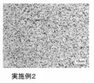
次に、秤量した粉末を粉砕媒体のタングステン合金ボールと共に容量10リットルのボールミルポットに封入し、120時間回転させて混合した。このようにして得られた混合粉をカーボン製の型に充填し、真空雰囲気中、温度980°C、保持時間2時間、加圧力30MPaの条件でホットプレスして焼結体を得た。さらにこれを旋盤で切削加工して直径が164mm、厚さが4mmの円盤状スパッタリングターゲットを得た。
このスパッタリングターゲット表面を研磨して組織をレーザー顕微鏡で観察した。図1において、白っぽく見える領域がCo、Ptの金属相であり、黒っぽく見える領域が酸化物相であった。そして、実施例1と同様の方法を用いて、粒子面積Sが10μm2以上、かつ、粒子面積Sと粒子の周囲の長さLとの比(S/L)が0.35以上である酸化物粒子の個数を計数したところ、単位面積当たりの平均個数は、0.0003個/μm2と良好な結果を示した。
次に、このターゲットをDCマグネトロンスパッタ装置に取り付けスパッタリングを行った。スパッタ条件は、スパッタパワー1.0kW、Arガス圧3.2Paとし、200秒間、4インチ径のシリコン基板上にスパッタした。そして、基板上に付着したパーティクルの個数をパーティクルカウンターで測定した。このときのシリコン基板上のパーティクル数は平均5個と極めて少ないレベルにあった。
(比較例1)
金属粉末として、Co粉末、Pt粉末を、非磁性材粉末として、B2O3粉末、TiO2粉末、SiO2粉末、CoO粉末を、用意した。そして、これらの粉末を以下の組成比で2000g秤量した。
組成(at%):Co-16.26Pt-3.25B-4.88Ti-1.63Si-18.7O
金属粉末として、Co粉末、Pt粉末を、非磁性材粉末として、B2O3粉末、TiO2粉末、SiO2粉末、CoO粉末を、用意した。そして、これらの粉末を以下の組成比で2000g秤量した。
組成(at%):Co-16.26Pt-3.25B-4.88Ti-1.63Si-18.7O
次に、秤量した粉末を粉砕媒体のタングステン合金ボールと共に容量10リットルのボールミルポットに封入し、120時間回転させて混合した。このようにして得られた混合粉をカーボン製の型に充填し、真空雰囲気中、温度980°C、保持時間2時間、加圧力30MPaの条件でホットプレスして焼結体を得た。さらにこれを旋盤で切削加工して直径が164mm、厚さが4mmの円盤状スパッタリングターゲットを得た。
このスパッタリングターゲット表面を研磨して組織をレーザー顕微鏡で観察した。図2において、白っぽく見える領域がCo、Ptの金属相であり、黒っぽく見える領域が酸化物相であった。そして、実施例1と同様の方法を用いて、粒子面積Sが10μm2以上、かつ、粒子面積Sと粒子の周囲の長さLとの比(S/L)が0.35以上である酸化物粒子の個数を計数したところ、単位面積当たりの平均個数は、0.0022個/μm2と増加していた。次に、実施例1と同様の条件でスパッタリングを行い、基板上に付着したパーティクルの個数をパーティクルカウンターで測定した。このときのシリコン基板上のパーティクル数は平均100個以上と非常に多いレベルにあった。
(比較例2)
金属粉末として、Co粉末、Pt粉末を、非磁性材粉末として、B2O3粉末、TiO2粉末、SiO2粉末、CoO粉末を、用意した。そして、これらの粉末を以下の組成比で2000g秤量した。
組成(at%):Co-15.63Pt-4.69B-3.91Ti-3.13Si-21.88O
金属粉末として、Co粉末、Pt粉末を、非磁性材粉末として、B2O3粉末、TiO2粉末、SiO2粉末、CoO粉末を、用意した。そして、これらの粉末を以下の組成比で2000g秤量した。
組成(at%):Co-15.63Pt-4.69B-3.91Ti-3.13Si-21.88O
次に、秤量した粉末を粉砕媒体のタングステン合金ボールと共に容量10リットルのボールミルポットに封入し、120時間回転させて混合した。このようにして得られた混合粉をカーボン製の型に充填し、真空雰囲気中、温度980°C、保持時間2時間、加圧力30MPaの条件でホットプレスして焼結体を得た。さらにこれを旋盤で切削加工して直径が164mm、厚さが4mmの円盤状スパッタリングターゲットを得た。
このスパッタリングターゲット表面を研磨して組織をレーザー顕微鏡で観察した。図2において、白っぽく見える領域がCo、Ptの金属相であり、黒っぽく見える領域が酸化物相であった。そして、実施例1と同様の方法を用いて、粒子面積Sが10μm2以上、かつ、粒子面積Sと粒子の周囲の長さLとの比(S/L)が0.35以上である酸化物粒子の個数を計数したところ、単位面積当たりの平均個数は、0.0032個/μm2と増加していた。次に、実施例1と同様の条件でスパッタリングを行い、基板上に付着したパーティクルの個数をパーティクルカウンターで測定した。このときのシリコン基板上のパーティクル数は平均100個以上と非常に多いレベルにあった。
(実施例3)
金属粉末として、Co粉末、Co-B粉末を、非磁性材粉末として、TiBO3粉末、TiO2粉末、SiO2粉末を、用意した。TiBO3粉末については、予め、Ti2O3粉末とB2O3粉末を混合、合成、粉砕したものを使用した。そして、これらの粉末を以下の組成比で2000g秤量した。
組成(at%):Co-3.39B-3.39Ti-3.39Si-15.25O
金属粉末として、Co粉末、Co-B粉末を、非磁性材粉末として、TiBO3粉末、TiO2粉末、SiO2粉末を、用意した。TiBO3粉末については、予め、Ti2O3粉末とB2O3粉末を混合、合成、粉砕したものを使用した。そして、これらの粉末を以下の組成比で2000g秤量した。
組成(at%):Co-3.39B-3.39Ti-3.39Si-15.25O
次に、秤量した粉末を粉砕媒体のタングステン合金ボールと共に容量10リットルのボールミルポットに封入し、120時間回転させて混合した。このようにして得られた混合粉をカーボン製の型に充填し、真空雰囲気中、温度980°C、保持時間2時間、加圧力30MPaの条件でホットプレスして焼結体を得た。さらにこれを旋盤で切削加工して直径が164mm、厚さが4mmの円盤状スパッタリングターゲットを得た。
このスパッタリングターゲット表面を研磨して組織をレーザー顕微鏡で観察した。実施例1と同様の方法を用いて、粒子面積Sが10μm2以上、かつ、粒子面積Sと粒子の周囲の長さLとの比(S/L)が0.35以上である酸化物粒子の個数を計数したところ、単位面積当たりの平均個数は、0.0002個/μm2と良好な結果を示した。次に、実施例1と同様の条件でスパッタリングを行い、基板上に付着したパーティクルの個数をパーティクルカウンターで測定した。このときのシリコン基板上のパーティクル数は平均6個と極めて少ないレベルにあった。
(実施例4)
金属粉末として、Fe粉末、Fe-B粉末、Pt粉末を、非磁性材粉末として、TiBO3粉末、TiO2粉末、MnO2粉末を、用意した。TiBO3粉末については、予め、Ti2O3粉末とB2O3粉末を混合、合成、粉砕したものを使用した。そして、これらの粉末を以下の組成比で2000g秤量した。
組成(at%):Fe-33.33Pt-3.33B-3.33Ti-4.17Mn-16.67O
金属粉末として、Fe粉末、Fe-B粉末、Pt粉末を、非磁性材粉末として、TiBO3粉末、TiO2粉末、MnO2粉末を、用意した。TiBO3粉末については、予め、Ti2O3粉末とB2O3粉末を混合、合成、粉砕したものを使用した。そして、これらの粉末を以下の組成比で2000g秤量した。
組成(at%):Fe-33.33Pt-3.33B-3.33Ti-4.17Mn-16.67O
次に、秤量した粉末を粉砕媒体の鋼球ボールと共に容量10リットルのボールミルポットに封入し、120時間回転させて混合した。このようにして得られた混合粉をカーボン製の型に充填し、真空雰囲気中、温度980°C、保持時間2時間、加圧力30MPaの条件でホットプレスして焼結体を得た。さらにこれを旋盤で切削加工して直径が164mm、厚さが4mmの円盤状スパッタリングターゲットを得た。
このスパッタリングターゲット表面を研磨して組織をレーザー顕微鏡で観察した。実施例1と同様の方法を用いて、粒子面積Sが10μm2以上、かつ、粒子面積Sと粒子の周囲の長さLとの比(S/L)が0.35以上である酸化物粒子の個数を計数したところ、単位面積当たりの平均個数は、0.0006個/μm2と良好な結果を示した。次に、実施例1と同様の条件でスパッタリングを行い、基板上に付着したパーティクルの個数をパーティクルカウンターで測定した。このときのシリコン基板上のパーティクル数は平均6個と極めて少ないレベルにあった。
本発明は、酸化物相の凝集(粗大化)を抑制することにより、スパッタリング時の非磁性材による異常放電を抑制することができる。本発明によれば、異常放電が原因となるスパッタリング中のパーティクル発生を減少させ、歩留まり向上によるコスト改善効果を得ることができるという優れた効果を有するので、磁気記録媒体の磁性体薄膜、特にハードディスクドライブ記録層の成膜に使用される強磁性材スパッタリングターゲットとして有用である。
Claims (4)
- Co又はFeを含む合金と少なくともTi、Bを含む酸化物を含有するスパッタリングターゲットであって、該スパッタリングターゲットにおいて、酸化物の粒子面積Sが10μm2以上、かつ、粒子面積Sと粒子の周囲の長さLとの比(S/L)が0.35以上である酸化物粒子の平均個数が0.0015個/μm2以下であることを特徴とするスパッタリングターゲット。
- 酸化物の粒子面積Sが10μm2以上、かつ、粒子面積Sと粒子の周囲の長さLとの比(S/L)が0.35以上である酸化物粒子の平均個数が0.0007個/μm2以下であることを特徴とする請求項1記載のスパッタリングターゲット。
- スパッタリングターゲットの組成において、酸化物を構成するBを0.5at%~15at%含有することを特徴とする請求項1又は2記載のスパッタリングターゲット。
- スパッタリングターゲットの組成において、酸化物を構成するTiを0.5at%~15at%含有することを特徴とする請求項1~3のいずれか一項に記載のスパッタリングターゲット。
Priority Applications (1)
| Application Number | Priority Date | Filing Date | Title |
|---|---|---|---|
| JP2016535848A JP6359662B2 (ja) | 2014-07-25 | 2015-06-18 | 磁性体薄膜形成用スパッタリングターゲット |
Applications Claiming Priority (2)
| Application Number | Priority Date | Filing Date | Title |
|---|---|---|---|
| JP2014152003 | 2014-07-25 | ||
| JP2014-152003 | 2014-07-25 |
Publications (1)
| Publication Number | Publication Date |
|---|---|
| WO2016013334A1 true WO2016013334A1 (ja) | 2016-01-28 |
Family
ID=55162869
Family Applications (1)
| Application Number | Title | Priority Date | Filing Date |
|---|---|---|---|
| PCT/JP2015/067539 Ceased WO2016013334A1 (ja) | 2014-07-25 | 2015-06-18 | 磁性体薄膜形成用スパッタリングターゲット |
Country Status (2)
| Country | Link |
|---|---|
| JP (1) | JP6359662B2 (ja) |
| WO (1) | WO2016013334A1 (ja) |
Cited By (6)
| Publication number | Priority date | Publication date | Assignee | Title |
|---|---|---|---|---|
| WO2020066114A1 (ja) * | 2018-09-25 | 2020-04-02 | Jx金属株式会社 | スパッタリングターゲット及びスパッタリングターゲットを製造するための粉体 |
| JP7625109B1 (ja) | 2024-03-29 | 2025-01-31 | Jx金属株式会社 | 磁性材ターゲット及び磁性材ターゲット組立品 |
| JP7625112B1 (ja) | 2024-03-29 | 2025-01-31 | Jx金属株式会社 | 磁性材ターゲット及び磁性材ターゲット組立品 |
| JP7625113B1 (ja) | 2024-03-29 | 2025-01-31 | Jx金属株式会社 | 磁性材ターゲット及び磁性材ターゲット組立品 |
| JP7625110B1 (ja) | 2024-03-29 | 2025-01-31 | Jx金属株式会社 | 磁性材ターゲット及び磁性材ターゲット組立品 |
| JP7625111B1 (ja) | 2024-03-29 | 2025-01-31 | Jx金属株式会社 | 磁性材ターゲット及び磁性材ターゲット組立品 |
Citations (4)
| Publication number | Priority date | Publication date | Assignee | Title |
|---|---|---|---|---|
| JP2009001860A (ja) * | 2007-06-21 | 2009-01-08 | Mitsubishi Materials Corp | 比透磁率の低い垂直磁気記録媒体膜形成用スパッタリングターゲット |
| WO2013013696A1 (de) * | 2011-07-22 | 2013-01-31 | Alfred Kärcher Gmbh & Co. Kg | Kehrmaschine mit druckbehälter zur abreinigung des filters |
| WO2013108520A1 (ja) * | 2012-01-18 | 2013-07-25 | Jx日鉱日石金属株式会社 | Co-Cr-Pt系スパッタリングターゲット及びその製造方法 |
| WO2013125469A1 (ja) * | 2012-02-22 | 2013-08-29 | Jx日鉱日石金属株式会社 | 磁性材スパッタリングターゲット及びその製造方法 |
Family Cites Families (2)
| Publication number | Priority date | Publication date | Assignee | Title |
|---|---|---|---|---|
| JPS6340766A (ja) * | 1986-08-01 | 1988-02-22 | 旭硝子株式会社 | 高温鉄鋼接触部材 |
| WO2013136962A1 (ja) * | 2012-03-15 | 2013-09-19 | Jx日鉱日石金属株式会社 | 磁性材スパッタリングターゲット及びその製造方法 |
-
2015
- 2015-06-18 WO PCT/JP2015/067539 patent/WO2016013334A1/ja not_active Ceased
- 2015-06-18 JP JP2016535848A patent/JP6359662B2/ja active Active
Patent Citations (4)
| Publication number | Priority date | Publication date | Assignee | Title |
|---|---|---|---|---|
| JP2009001860A (ja) * | 2007-06-21 | 2009-01-08 | Mitsubishi Materials Corp | 比透磁率の低い垂直磁気記録媒体膜形成用スパッタリングターゲット |
| WO2013013696A1 (de) * | 2011-07-22 | 2013-01-31 | Alfred Kärcher Gmbh & Co. Kg | Kehrmaschine mit druckbehälter zur abreinigung des filters |
| WO2013108520A1 (ja) * | 2012-01-18 | 2013-07-25 | Jx日鉱日石金属株式会社 | Co-Cr-Pt系スパッタリングターゲット及びその製造方法 |
| WO2013125469A1 (ja) * | 2012-02-22 | 2013-08-29 | Jx日鉱日石金属株式会社 | 磁性材スパッタリングターゲット及びその製造方法 |
Cited By (13)
| Publication number | Priority date | Publication date | Assignee | Title |
|---|---|---|---|---|
| WO2020066114A1 (ja) * | 2018-09-25 | 2020-04-02 | Jx金属株式会社 | スパッタリングターゲット及びスパッタリングターゲットを製造するための粉体 |
| JPWO2020066114A1 (ja) * | 2018-09-25 | 2021-10-21 | Jx金属株式会社 | スパッタリングターゲット及びスパッタリングターゲットの製造方法 |
| JP7072664B2 (ja) | 2018-09-25 | 2022-05-20 | Jx金属株式会社 | スパッタリングターゲット及びスパッタリングターゲットの製造方法 |
| JP7625109B1 (ja) | 2024-03-29 | 2025-01-31 | Jx金属株式会社 | 磁性材ターゲット及び磁性材ターゲット組立品 |
| JP7625112B1 (ja) | 2024-03-29 | 2025-01-31 | Jx金属株式会社 | 磁性材ターゲット及び磁性材ターゲット組立品 |
| JP7625113B1 (ja) | 2024-03-29 | 2025-01-31 | Jx金属株式会社 | 磁性材ターゲット及び磁性材ターゲット組立品 |
| JP7625110B1 (ja) | 2024-03-29 | 2025-01-31 | Jx金属株式会社 | 磁性材ターゲット及び磁性材ターゲット組立品 |
| JP7625111B1 (ja) | 2024-03-29 | 2025-01-31 | Jx金属株式会社 | 磁性材ターゲット及び磁性材ターゲット組立品 |
| JP2025154879A (ja) * | 2024-03-29 | 2025-10-10 | Jx金属株式会社 | 磁性材ターゲット及び磁性材ターゲット組立品 |
| JP2025154891A (ja) * | 2024-03-29 | 2025-10-10 | Jx金属株式会社 | 磁性材ターゲット及び磁性材ターゲット組立品 |
| JP2025154883A (ja) * | 2024-03-29 | 2025-10-10 | Jx金属株式会社 | 磁性材ターゲット及び磁性材ターゲット組立品 |
| JP2025154900A (ja) * | 2024-03-29 | 2025-10-10 | Jx金属株式会社 | 磁性材ターゲット及び磁性材ターゲット組立品 |
| JP2025154895A (ja) * | 2024-03-29 | 2025-10-10 | Jx金属株式会社 | 磁性材ターゲット及び磁性材ターゲット組立品 |
Also Published As
| Publication number | Publication date |
|---|---|
| JP6359662B2 (ja) | 2018-07-18 |
| JPWO2016013334A1 (ja) | 2017-04-27 |
Similar Documents
| Publication | Publication Date | Title |
|---|---|---|
| JP5946974B1 (ja) | スパッタリングターゲット | |
| JP6359662B2 (ja) | 磁性体薄膜形成用スパッタリングターゲット | |
| JP5829747B2 (ja) | 磁性材スパッタリングターゲット及びその製造方法 | |
| WO2013136962A1 (ja) | 磁性材スパッタリングターゲット及びその製造方法 | |
| JP6359622B2 (ja) | Co又はFeを含有するスパッタリングターゲット | |
| JP5847203B2 (ja) | Co−Cr−Pt系スパッタリングターゲット及びその製造方法 | |
| WO2018123500A1 (ja) | 磁性材スパッタリングターゲット及びその製造方法 | |
| JP6881643B2 (ja) | 磁気記録媒体用スパッタリングターゲット及び磁性薄膜 | |
| JP5801496B2 (ja) | スパッタリングターゲット | |
| JP6305881B2 (ja) | 磁気記録媒体用スパッタリングターゲット | |
| JP6005767B2 (ja) | 磁性記録媒体用スパッタリングターゲット | |
| JP6545898B2 (ja) | 強磁性材スパッタリングターゲット | |
| JP6553755B2 (ja) | 磁気記録媒体用スパッタリングターゲット及び磁性薄膜 | |
| JP7153729B2 (ja) | スパッタリングターゲット及び磁性膜 | |
| JP7317741B2 (ja) | スパッタリングターゲット、磁性膜、及びスパッタリングターゲット作製用の原料混合粉末 | |
| CN111183243A (zh) | 溅射靶、磁性膜和磁性膜的制造方法 | |
| TW202010855A (zh) | 濺鍍靶、磁性膜和磁性膜的製造方法 | |
| JP2018172762A (ja) | スパッタリングターゲット、磁性膜および、磁性膜の製造方法 |
Legal Events
| Date | Code | Title | Description |
|---|---|---|---|
| 121 | Ep: the epo has been informed by wipo that ep was designated in this application |
Ref document number: 15825106 Country of ref document: EP Kind code of ref document: A1 |
|
| ENP | Entry into the national phase |
Ref document number: 2016535848 Country of ref document: JP Kind code of ref document: A |
|
| NENP | Non-entry into the national phase |
Ref country code: DE |
|
| 122 | Ep: pct application non-entry in european phase |
Ref document number: 15825106 Country of ref document: EP Kind code of ref document: A1 |