WO2016009899A1 - Inductance montée en surface et son procédé de fabrication - Google Patents
Inductance montée en surface et son procédé de fabrication Download PDFInfo
- Publication number
- WO2016009899A1 WO2016009899A1 PCT/JP2015/069526 JP2015069526W WO2016009899A1 WO 2016009899 A1 WO2016009899 A1 WO 2016009899A1 JP 2015069526 W JP2015069526 W JP 2015069526W WO 2016009899 A1 WO2016009899 A1 WO 2016009899A1
- Authority
- WO
- WIPO (PCT)
- Prior art keywords
- coil
- winding
- molded body
- outer periphery
- size
- Prior art date
Links
- 238000004519 manufacturing process Methods 0.000 title claims description 15
- 238000004804 winding Methods 0.000 claims abstract description 105
- 229920005989 resin Polymers 0.000 claims abstract description 26
- 239000011347 resin Substances 0.000 claims abstract description 26
- 238000000465 moulding Methods 0.000 claims abstract description 23
- 238000000034 method Methods 0.000 claims abstract description 22
- 239000000696 magnetic material Substances 0.000 claims abstract description 14
- 239000000843 powder Substances 0.000 claims abstract description 5
- 239000003566 sealing material Substances 0.000 claims description 23
- 239000004020 conductor Substances 0.000 claims description 3
- 230000006866 deterioration Effects 0.000 abstract 1
- 238000007789 sealing Methods 0.000 abstract 1
- 239000006247 magnetic powder Substances 0.000 description 6
- 239000002184 metal Substances 0.000 description 6
- 229910052751 metal Inorganic materials 0.000 description 6
- XEEYBQQBJWHFJM-UHFFFAOYSA-N Iron Chemical compound [Fe] XEEYBQQBJWHFJM-UHFFFAOYSA-N 0.000 description 4
- 230000002093 peripheral effect Effects 0.000 description 4
- 239000011248 coating agent Substances 0.000 description 3
- 238000000576 coating method Methods 0.000 description 3
- 239000000463 material Substances 0.000 description 3
- 238000007493 shaping process Methods 0.000 description 3
- 239000003822 epoxy resin Substances 0.000 description 2
- 230000004907 flux Effects 0.000 description 2
- 239000011521 glass Substances 0.000 description 2
- 229910052742 iron Inorganic materials 0.000 description 2
- 239000000203 mixture Substances 0.000 description 2
- 229920000647 polyepoxide Polymers 0.000 description 2
- 230000015572 biosynthetic process Effects 0.000 description 1
- 229910052802 copper Inorganic materials 0.000 description 1
- 229910052737 gold Inorganic materials 0.000 description 1
- 239000012212 insulator Substances 0.000 description 1
- 229910052759 nickel Inorganic materials 0.000 description 1
- 229910052763 palladium Inorganic materials 0.000 description 1
- 239000005011 phenolic resin Substances 0.000 description 1
- 238000005498 polishing Methods 0.000 description 1
- 238000007517 polishing process Methods 0.000 description 1
- 229920006122 polyamide resin Polymers 0.000 description 1
- 229920013716 polyethylene resin Polymers 0.000 description 1
- 229920001721 polyimide Polymers 0.000 description 1
- 239000009719 polyimide resin Substances 0.000 description 1
- 229920005992 thermoplastic resin Polymers 0.000 description 1
- 229920001187 thermosetting polymer Polymers 0.000 description 1
- 229910052718 tin Inorganic materials 0.000 description 1
- 229910000859 α-Fe Inorganic materials 0.000 description 1
Images


Classifications
-
- H—ELECTRICITY
- H01—ELECTRIC ELEMENTS
- H01F—MAGNETS; INDUCTANCES; TRANSFORMERS; SELECTION OF MATERIALS FOR THEIR MAGNETIC PROPERTIES
- H01F27/00—Details of transformers or inductances, in general
- H01F27/28—Coils; Windings; Conductive connections
- H01F27/29—Terminals; Tapping arrangements for signal inductances
- H01F27/292—Surface mounted devices
-
- H—ELECTRICITY
- H01—ELECTRIC ELEMENTS
- H01F—MAGNETS; INDUCTANCES; TRANSFORMERS; SELECTION OF MATERIALS FOR THEIR MAGNETIC PROPERTIES
- H01F17/00—Fixed inductances of the signal type
- H01F17/04—Fixed inductances of the signal type with magnetic core
-
- H—ELECTRICITY
- H01—ELECTRIC ELEMENTS
- H01F—MAGNETS; INDUCTANCES; TRANSFORMERS; SELECTION OF MATERIALS FOR THEIR MAGNETIC PROPERTIES
- H01F27/00—Details of transformers or inductances, in general
- H01F27/08—Cooling; Ventilating
-
- H—ELECTRICITY
- H01—ELECTRIC ELEMENTS
- H01F—MAGNETS; INDUCTANCES; TRANSFORMERS; SELECTION OF MATERIALS FOR THEIR MAGNETIC PROPERTIES
- H01F27/00—Details of transformers or inductances, in general
- H01F27/28—Coils; Windings; Conductive connections
-
- H—ELECTRICITY
- H01—ELECTRIC ELEMENTS
- H01F—MAGNETS; INDUCTANCES; TRANSFORMERS; SELECTION OF MATERIALS FOR THEIR MAGNETIC PROPERTIES
- H01F27/00—Details of transformers or inductances, in general
- H01F27/28—Coils; Windings; Conductive connections
- H01F27/2823—Wires
- H01F27/2828—Construction of conductive connections, of leads
-
- H—ELECTRICITY
- H01—ELECTRIC ELEMENTS
- H01F—MAGNETS; INDUCTANCES; TRANSFORMERS; SELECTION OF MATERIALS FOR THEIR MAGNETIC PROPERTIES
- H01F27/00—Details of transformers or inductances, in general
- H01F27/28—Coils; Windings; Conductive connections
- H01F27/29—Terminals; Tapping arrangements for signal inductances
-
- H—ELECTRICITY
- H01—ELECTRIC ELEMENTS
- H01F—MAGNETS; INDUCTANCES; TRANSFORMERS; SELECTION OF MATERIALS FOR THEIR MAGNETIC PROPERTIES
- H01F27/00—Details of transformers or inductances, in general
- H01F27/28—Coils; Windings; Conductive connections
- H01F27/32—Insulating of coils, windings, or parts thereof
-
- H—ELECTRICITY
- H01—ELECTRIC ELEMENTS
- H01F—MAGNETS; INDUCTANCES; TRANSFORMERS; SELECTION OF MATERIALS FOR THEIR MAGNETIC PROPERTIES
- H01F41/00—Apparatus or processes specially adapted for manufacturing or assembling magnets, inductances or transformers; Apparatus or processes specially adapted for manufacturing materials characterised by their magnetic properties
- H01F41/02—Apparatus or processes specially adapted for manufacturing or assembling magnets, inductances or transformers; Apparatus or processes specially adapted for manufacturing materials characterised by their magnetic properties for manufacturing cores, coils, or magnets
- H01F41/0206—Manufacturing of magnetic cores by mechanical means
- H01F41/0246—Manufacturing of magnetic circuits by moulding or by pressing powder
-
- H—ELECTRICITY
- H01—ELECTRIC ELEMENTS
- H01F—MAGNETS; INDUCTANCES; TRANSFORMERS; SELECTION OF MATERIALS FOR THEIR MAGNETIC PROPERTIES
- H01F41/00—Apparatus or processes specially adapted for manufacturing or assembling magnets, inductances or transformers; Apparatus or processes specially adapted for manufacturing materials characterised by their magnetic properties
- H01F41/02—Apparatus or processes specially adapted for manufacturing or assembling magnets, inductances or transformers; Apparatus or processes specially adapted for manufacturing materials characterised by their magnetic properties for manufacturing cores, coils, or magnets
- H01F41/04—Apparatus or processes specially adapted for manufacturing or assembling magnets, inductances or transformers; Apparatus or processes specially adapted for manufacturing materials characterised by their magnetic properties for manufacturing cores, coils, or magnets for manufacturing coils
- H01F41/06—Coil winding
- H01F41/076—Forming taps or terminals while winding, e.g. by wrapping or soldering the wire onto pins, or by directly forming terminals from the wire
-
- H—ELECTRICITY
- H01—ELECTRIC ELEMENTS
- H01F—MAGNETS; INDUCTANCES; TRANSFORMERS; SELECTION OF MATERIALS FOR THEIR MAGNETIC PROPERTIES
- H01F17/00—Fixed inductances of the signal type
- H01F17/04—Fixed inductances of the signal type with magnetic core
- H01F2017/048—Fixed inductances of the signal type with magnetic core with encapsulating core, e.g. made of resin and magnetic powder
-
- Y—GENERAL TAGGING OF NEW TECHNOLOGICAL DEVELOPMENTS; GENERAL TAGGING OF CROSS-SECTIONAL TECHNOLOGIES SPANNING OVER SEVERAL SECTIONS OF THE IPC; TECHNICAL SUBJECTS COVERED BY FORMER USPC CROSS-REFERENCE ART COLLECTIONS [XRACs] AND DIGESTS
- Y10—TECHNICAL SUBJECTS COVERED BY FORMER USPC
- Y10T—TECHNICAL SUBJECTS COVERED BY FORMER US CLASSIFICATION
- Y10T29/00—Metal working
- Y10T29/49—Method of mechanical manufacture
- Y10T29/49002—Electrical device making
- Y10T29/4902—Electromagnet, transformer or inductor
Definitions
- the present invention relates to a surface mount inductor including a coil formed by winding a conductive wire, and a molded body containing a coil formed using a sealing material including a resin and a magnetic material, and a method for manufacturing the same.
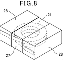
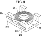
- a coil 21 is formed by winding a conductive wire on a conventional surface mount inductor, and this coil 21 is embedded in a molded body 27 formed of a sealing material containing magnetic powder and resin. There is one in which the coil 21 is connected to an external terminal 28 formed on the surface of the molded body 27 (see, for example, JP 2010-245473 A).
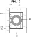
- this surface-mount inductor is configured such that a coil 21 formed by winding a conductive wire is placed on a tablet 22, and a lead-out end 21 b of the coil 21 is placed on a columnar protrusion of the tablet 22 as shown in FIG.
- the coil and the tablet are arranged in the molding die so as to be sandwiched between the inner wall surface of the molding die 24 along the outer side surface of the portion 22a.
- the molded object 27 which incorporates the coil 21 by the resin molding method or the compacting method is formed using this metal mold
- such a conventional surface-mount inductor is a molded body in which a coil is built in by a resin molding method or a powder molding method in a state where the lead end of the coil is sandwiched between the columnar convex portion of the tablet and the inner wall surface of the molding die. Since the shape of the tablet is complicated, the shape of the coil cannot be increased, and the area of the coil winding portion and the cross-sectional area of the conductive wire are reduced, resulting in poor superimposed current value Idc and resistance value Rdc. It was.
- An object of one or more embodiments of the present invention is to provide a surface-mount inductor that can improve the superimposed current value Idc and the resistance value Rdc and can be manufactured at low cost, and a manufacturing method thereof.
- a surface mount inductor including a coil formed by winding a conducting wire and a sealing material including a resin and a magnetic material, and including a molded body incorporating the coil. Is formed by winding a conducting wire so that the lead end is positioned on the outer periphery of the winding portion, and the molded body has a coil surface partially exposed on four side surfaces parallel to the coil winding axis. The area of the outer part of the winding part of the coil is formed so that the area of the part outside the outer periphery of the coil is substantially the same as or smaller than the area of the inner part of the coil winding part.
- one or more embodiments of the present invention use a coil formed by winding a conducting wire and a sealing material including a resin and a magnetic material, and a surface-mount inductor including a molded body incorporating the coil.
- a coil is formed by winding a conducting wire so that the leading end is positioned on the outer periphery of the winding part, and the coil is arranged between a pair of plate-like tablets formed using a sealing material
- the molded body Forming the molded body so that the area of the inner part of the winding part is substantially the same as or smaller than the area of the inner periphery of the winding part, and an external terminal connected to the lead-out end of the coil on the surface of the molded body Forming.
- a surface mount inductor including a coil formed by winding a conducting wire and a sealing material including a resin and a magnetic material, and including a molded body incorporating the coil. Is formed by winding a conducting wire so that the lead end is positioned on the outer periphery of the winding portion, and the molded body has a coil surface partially exposed on four side surfaces parallel to the coil winding axis.
- the area of the outer part of the outer periphery of the winding part of the coil is formed so that it is substantially the same as or smaller than the area of the inner part of the inner part of the winding part of the coil,
- the built-in coil can be enlarged, and the superimposed current value Idc and the resistance value Rdc can be improved.
- the structure of the tablet for forming the molded body can be simplified, and the tablet can be easily made.
- one or more embodiments of the present invention use a coil formed by winding a conducting wire and a sealing material including a resin and a magnetic material, and a surface-mount inductor including a molded body incorporating the coil.
- a coil is formed by winding a conducting wire so that the leading end is positioned on the outer periphery of the winding part, and the coil is arranged between a pair of plate-like tablets formed using a sealing material
- the coil is partially exposed on the four side surfaces parallel to the winding axis of the coil, and the area of the outer portion of the coil winding portion is smaller than the coil.
- FIG. 1 is a perspective view showing an embodiment of a surface mount inductor according to the present invention. It is a perspective view which shows arrangement
- One or more embodiments of the present invention include a molded body including a coil formed by winding a conductive wire and a coil formed using a sealing material including a resin and a magnetic material.
- the coil has a winding portion around which a conducting wire is wound so that both ends thereof are positioned on the outer periphery, and a lead-out end portion drawn from the outer periphery of the winding portion.
- the surface of the coil is partially exposed on four side surfaces parallel to the coil winding axis, and the area of the outer portion of the coil winding portion is larger than the inner periphery of the coil winding portion. It is formed so as to be substantially the same as or smaller than the area of the inner part.
- one or more embodiments of the present invention can increase the outer size of the coil to the maximum within the range of the outer size of the molded body, and thus reduce the dead space of the molded body. It is possible to increase the diameter of the winding axis of the coil and the cross-sectional area of the conducting wire.
- a coil is formed by winding a conducting wire such that the leading end is positioned on the outer periphery of the winding portion.
- the coil is arranged between a pair of plate-like tablets formed using a sealing material and having the same size as the outer circumference of the coil, and these are integrated using a resin molding method.
- the coil is partially exposed on four side surfaces parallel to the winding axis of the coil, and the area of the outer part of the coil winding part is substantially the same as the area of the inner part of the coil winding part.
- the molded body is formed to be the same or smaller.
- an external terminal connected to the coil drawing end is formed on the surface of the molded body. Therefore, the manufacturing method of the surface mount inductor according to the present invention can increase the outer size of the coil to the limit within the range of the outer size of the molded body, so that the dead space of the molded body can be reduced. It is possible to increase the diameter of the winding axis of the coil and the cross-sectional area of the conducting wire.
- FIG. 1 is a perspective view showing a state where a molded body of a surface mount inductor according to an embodiment of the present invention is seen through
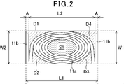
- FIG. 2 is a view where the inside of the molded body of a surface mounted inductor according to the present invention is seen through.
- 11 is a coil
- 17 is a molded body.
- the coil 11 includes a winding part 11a in which a conducting wire is wound in a spiral shape so that both ends thereof are positioned on the outer periphery, and a drawing end part 11b drawn from the winding part 11a.
- An air core coil is formed.
- the conducting wire is a rectangular wire having a rectangular cross section.
- the winding part 11a is formed in an elliptical shape.
- the lead-out end portion 11b is formed such that both ends of the conducting wire are drawn out from the winding portion 11a so as to face each other with the winding portion 11a interposed therebetween, and further bent in a direction opposite to the drawn-out direction.
- the molded body 17 is formed so as to incorporate the coil 11 using a sealing material including a resin and a magnetic material.
- a sealing material for example, an iron-based metal magnetic powder is used as a magnetic material, and an epoxy resin is used as a resin, and a mixture thereof is used.
- the size W1 of the molded body 17 in the width direction is formed to be approximately the same as the size W2 of the outer circumference in the minor axis direction of the winding portion 11a of the coil 11.
- the length L1 of the molded body 17 is such that the outer diameter L2 of the winding portion 11a of the coil 11 in the longitudinal direction, the thickness A of one of the leading ends 11b, and the thickness A of the other leading end 11b. It is approximately the same size as the sum of the thickness A or slightly larger.
- a part of the surface in the minor axis direction of the winding portion 11 a of the coil 11 is exposed on the opposite side surfaces of the molded body 17 in the width direction.
- the surface of the lead-out end portion 11 b of the coil 11 is exposed on the side surfaces of the molded body 17 facing in the length direction.
- the total area of the portions D1, D2, D3, D4 outside the outer peripheral surface of the winding part 11a of the coil 11 of the molded body 17 is the part inside the inner peripheral surface of the winding part 11a of the coil 11. It is formed to be substantially the same as S1 or smaller.
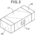
- a pair of external terminals 18 is formed on the surface of the molded body 17 as shown in FIG.
- the coil 11 is connected between the pair of external terminals 18 by connecting the drawn end portions 11 b of the coils 11 exposed on the opposite side surfaces in the length direction of the molded body 17 to the external terminals 18.
- Such a surface mount inductor is manufactured as follows. First, after forming a winding part by winding a conductive wire coated with a rectangular insulating coating in a spiral shape so that both ends thereof are positioned on the outer periphery, and then winding both ends of the conductive wire
- the air core coil is formed by being drawn from the outer periphery of the turning portion and further bent to form a lead end portion.
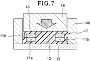
- the outer periphery of the coil 11 is used. Plate-shaped tablets 12 and 13 having approximately the same size are formed. Next, as shown in FIG.
- the winding part 11a and the leading end part 11b are The provided air-core coil is placed between the pair of plate-like tablets 12 and 13, and the punch 16 is set in the cavity of the molding die in this state.
- the air core coil 11 is built in by molding a pair of plate-like tablets and air core coils by a so-called resin molding method in which the mold is punched by a mold and a punch at 120 to 250 ° C. A molded body 17 is formed.
- the formed body 17 has a part of the surface in the short diameter direction of the winding portion 11a of the coil 11 on the side surface facing in the width direction, and the surface of the leading end portion 11b of the coil 11 on the side surface facing in the length direction.
- the area of the portion outside the outer peripheral surface of the winding portion 11a of the coil 11 is larger than the inner peripheral surface of the winding portion 11a of the coil 11. Is formed to be substantially the same as or smaller than the area of the inner portion.
- the molded body 17 formed in this way is subjected to a treatment for peeling off the insulating coating on the lead-out end portion 11b of the coil 11 exposed on the opposite side surfaces in the length direction and a barrel polishing treatment.
- the process of peeling off the insulating coating and the barrel polishing process can be performed simultaneously.
- an external terminal material containing a conductive material is applied to the surface of the molded body 17 and cured to form external terminals 18 on the surface of the molded body 17.
- the external terminal 18 may be plated with a material appropriately selected from one or more of Ni, Sn, Cu, Au, Pd and the like.
- the present invention is not limited to this embodiment.
- iron-based metal magnetic powder is used as the sealing material as the sealing material
- epoxy resin is used as the resin.
- the metal magnetic powder of another composition is used as the filling material, and the surface is coated with an insulator such as glass.
- Metal magnetic powder, metal magnetic powder with modified surface, ferrite powder, glass powder, etc. may be used.
- the resin a thermosetting resin such as a polyimide resin or a phenol resin, or a thermoplastic resin such as a polyethylene resin or a polyamide resin may be used.
- the coil may have a winding portion formed in a circular shape.
- the molded body has a coil placed on a plate-like tablet formed using a sealing material in a cavity of a molding die, and a powdery sealing material is filled on the coil, and these are resin molded.
- a compacting method to expose the surface in the short diameter direction of the coil winding portion on the surfaces of two opposite side surfaces in the width direction, and outside the outer periphery of the coil winding portion Is formed so that the area of the part of the coil is substantially the same as or smaller than the area of the inner part of the coil winding part, and the coil is drawn out on the surfaces of the two opposite side surfaces in the length direction.
- the surface of the end portion may be exposed.
Abstract
Étant donné qu'un corps moulé incorporant une bobine est formé par un procédé de moulage de résine ou un procédé de moulage par compression de poudre avec les extrémités principales de la bobine prises en sandwich entre une saillie en forme de colonne d'une tablette et une surface de paroi intérieure d'une matrice de moulage, la forme de la tablette devient compliquée et la taille de la bobine ne peut pas être augmentée, nécessitant une réduction de l'aire d'une section d'axe d'enroulement de la bobine ou de l'aire de section d'un fil conducteur, et une détérioration de la valeur de courant superposé et de la valeur de résistance. La présente invention produit un corps moulé incorporant une bobine par utilisation : d'une bobine formée par enroulement d'un fil conducteur ; et d'un élément d'étanchéité comprenant une résine et un matériau magnétique. La bobine est formée par enroulement du fil conducteur de manière que ses extrémités principales soient placées à la périphérie extérieure de l'enroulement. Le corps moulé est formé de manière que la surface de la bobine soit partiellement exposée au niveau de quatre surfaces latérales du corps moulé qui sont parallèles à l'axe d'enroulement de la bobine, et de manière que l'aire d'une partie située à l'extérieur de la périphérie extérieure de l'enroulement de la bobine soit sensiblement égale à l'aire d'une partie située à l'intérieur de la périphérie intérieure de l'enroulement de la bobine, ou plus petite qu'elle.
Priority Applications (4)
| Application Number | Priority Date | Filing Date | Title |
|---|---|---|---|
| KR1020177001313A KR101866150B1 (ko) | 2014-07-18 | 2015-07-07 | 표면 실장 인덕터 및 그 제조 방법 |
| CN201580039109.9A CN106575563B (zh) | 2014-07-18 | 2015-07-07 | 表面安装电感器及其制造方法 |
| US15/407,727 US10847309B2 (en) | 2014-07-18 | 2017-01-17 | Surface mounted inductor and manufacturing method therefor |
| US17/074,168 US11908611B2 (en) | 2014-07-18 | 2020-10-19 | Manufacturing method for surface mounted inductor |
Applications Claiming Priority (2)
| Application Number | Priority Date | Filing Date | Title |
|---|---|---|---|
| JP2014-147486 | 2014-07-18 | ||
| JP2014147486A JP6060116B2 (ja) | 2014-07-18 | 2014-07-18 | 表面実装インダクタ及びその製造方法 |
Related Child Applications (1)
| Application Number | Title | Priority Date | Filing Date |
|---|---|---|---|
| US15/407,727 Continuation US10847309B2 (en) | 2014-07-18 | 2017-01-17 | Surface mounted inductor and manufacturing method therefor |
Publications (1)
| Publication Number | Publication Date |
|---|---|
| WO2016009899A1 true WO2016009899A1 (fr) | 2016-01-21 |
Family
ID=55078395
Family Applications (1)
| Application Number | Title | Priority Date | Filing Date |
|---|---|---|---|
| PCT/JP2015/069526 WO2016009899A1 (fr) | 2014-07-18 | 2015-07-07 | Inductance montée en surface et son procédé de fabrication |
Country Status (5)
| Country | Link |
|---|---|
| US (2) | US10847309B2 (fr) |
| JP (1) | JP6060116B2 (fr) |
| KR (1) | KR101866150B1 (fr) |
| CN (1) | CN106575563B (fr) |
| WO (1) | WO2016009899A1 (fr) |
Cited By (2)
| Publication number | Priority date | Publication date | Assignee | Title |
|---|---|---|---|---|
| KR101792389B1 (ko) | 2016-01-29 | 2017-11-20 | 삼성전기주식회사 | 코일 전자부품 |
| CN113972048A (zh) * | 2021-10-29 | 2022-01-25 | 深圳市斯比特电子有限公司 | 快速装配式磁集成器件 |
Families Citing this family (18)
| Publication number | Priority date | Publication date | Assignee | Title |
|---|---|---|---|---|
| JP6341138B2 (ja) * | 2015-04-10 | 2018-06-13 | 株式会社村田製作所 | 面実装インダクタ及びその製造方法 |
| JP6388015B2 (ja) * | 2016-11-17 | 2018-09-12 | Tdk株式会社 | コイル部品およびコイル装置 |
| JP2018182209A (ja) * | 2017-04-19 | 2018-11-15 | 株式会社村田製作所 | コイル部品 |
| CN107359045B (zh) * | 2017-07-17 | 2022-03-25 | 广州市精程达精密机械有限公司 | 一种弯角成型机 |
| KR102484848B1 (ko) * | 2017-09-20 | 2023-01-05 | 삼성전기주식회사 | 박막형 칩 전자부품 |
| JP7372747B2 (ja) * | 2018-03-16 | 2023-11-01 | 日東電工株式会社 | 配線回路基板およびその製造方法 |
| WO2019239671A1 (fr) * | 2018-06-15 | 2019-12-19 | アルプスアルパイン株式会社 | Noyau de poudre moulé intégré dans une bobine, élément d'inductance et dispositif électronique/électrique |
| JP6922871B2 (ja) * | 2018-09-28 | 2021-08-18 | 株式会社村田製作所 | インダクタ部品およびインダクタ部品の製造方法 |
| JP2020077795A (ja) * | 2018-11-08 | 2020-05-21 | 株式会社村田製作所 | 表面実装インダクタ |
| KR102176279B1 (ko) * | 2019-05-03 | 2020-11-09 | 삼성전기주식회사 | 코일 전자 부품 |
| JP7373930B2 (ja) * | 2019-06-28 | 2023-11-06 | 太陽誘電株式会社 | 積層コイル部品 |
| US20210035730A1 (en) * | 2019-07-31 | 2021-02-04 | Murata Manufacturing Co., Ltd. | Inductor |
| CN110718359A (zh) * | 2019-11-08 | 2020-01-21 | 汕头市信技电子科技有限公司 | 一种表面贴装一体成型电感器的制造结构及其方法 |
| JP7456239B2 (ja) | 2020-03-31 | 2024-03-27 | 株式会社村田製作所 | インダクタ |
| JP7279688B2 (ja) * | 2020-06-08 | 2023-05-23 | 株式会社村田製作所 | インダクタ |
| KR102414826B1 (ko) * | 2020-06-18 | 2022-06-30 | 삼성전기주식회사 | 코일 부품 |
| CN112382479B (zh) * | 2020-10-21 | 2022-09-23 | 惠州市明大精密电子有限公司 | 一种工字电感及其制作方法 |
| CN113470966B (zh) * | 2021-07-15 | 2022-05-20 | 合泰盟方电子(深圳)股份有限公司 | 一种电感成型系统及成型工艺 |
Citations (2)
| Publication number | Priority date | Publication date | Assignee | Title |
|---|---|---|---|---|
| JP2010283119A (ja) * | 2009-06-04 | 2010-12-16 | Denso Corp | リアクトル |
| JP2014049597A (ja) * | 2012-08-31 | 2014-03-17 | Toko Inc | 面実装インダクタ及びその製造方法 |
Family Cites Families (9)
| Publication number | Priority date | Publication date | Assignee | Title |
|---|---|---|---|---|
| JP3201309B2 (ja) * | 1997-05-23 | 2001-08-20 | 株式会社村田製作所 | 積層型コイル及びその製造方法 |
| JP4933830B2 (ja) * | 2006-05-09 | 2012-05-16 | スミダコーポレーション株式会社 | インダクタ |
| JP2008124162A (ja) * | 2006-11-10 | 2008-05-29 | Toko Inc | 低背型チップコイルとその製造方法 |
| JP4714779B2 (ja) * | 2009-04-10 | 2011-06-29 | 東光株式会社 | 表面実装インダクタの製造方法とその表面実装インダクタ |
| JP2012160507A (ja) * | 2011-01-31 | 2012-08-23 | Toko Inc | 面実装インダクタと面実装インダクタの製造方法 |
| JP2013110184A (ja) * | 2011-11-18 | 2013-06-06 | Toko Inc | 面実装インダクタの製造方法とその面実装インダクタ |
| JP5623446B2 (ja) * | 2012-03-02 | 2014-11-12 | 東光株式会社 | 面実装インダクタの製造方法 |
| KR101771731B1 (ko) * | 2012-08-28 | 2017-08-25 | 삼성전기주식회사 | 적층 칩 전자부품 |
| JP5894119B2 (ja) * | 2013-06-14 | 2016-03-23 | 東光株式会社 | 面実装インダクタの製造方法 |
-
2014
- 2014-07-18 JP JP2014147486A patent/JP6060116B2/ja active Active
-
2015
- 2015-07-07 CN CN201580039109.9A patent/CN106575563B/zh active Active
- 2015-07-07 WO PCT/JP2015/069526 patent/WO2016009899A1/fr active Application Filing
- 2015-07-07 KR KR1020177001313A patent/KR101866150B1/ko active IP Right Grant
-
2017
- 2017-01-17 US US15/407,727 patent/US10847309B2/en active Active
-
2020
- 2020-10-19 US US17/074,168 patent/US11908611B2/en active Active
Patent Citations (2)
| Publication number | Priority date | Publication date | Assignee | Title |
|---|---|---|---|---|
| JP2010283119A (ja) * | 2009-06-04 | 2010-12-16 | Denso Corp | リアクトル |
| JP2014049597A (ja) * | 2012-08-31 | 2014-03-17 | Toko Inc | 面実装インダクタ及びその製造方法 |
Cited By (3)
| Publication number | Priority date | Publication date | Assignee | Title |
|---|---|---|---|---|
| KR101792389B1 (ko) | 2016-01-29 | 2017-11-20 | 삼성전기주식회사 | 코일 전자부품 |
| CN113972048A (zh) * | 2021-10-29 | 2022-01-25 | 深圳市斯比特电子有限公司 | 快速装配式磁集成器件 |
| CN113972048B (zh) * | 2021-10-29 | 2022-05-17 | 深圳市斯比特电子有限公司 | 快速装配式磁集成器件 |
Also Published As
| Publication number | Publication date |
|---|---|
| US20210035731A1 (en) | 2021-02-04 |
| KR20170019439A (ko) | 2017-02-21 |
| JP6060116B2 (ja) | 2017-01-11 |
| US11908611B2 (en) | 2024-02-20 |
| CN106575563A (zh) | 2017-04-19 |
| US10847309B2 (en) | 2020-11-24 |
| JP2016025180A (ja) | 2016-02-08 |
| CN106575563B (zh) | 2018-10-26 |
| KR101866150B1 (ko) | 2018-06-08 |
| US20170125158A1 (en) | 2017-05-04 |
Similar Documents
| Publication | Publication Date | Title |
|---|---|---|
| WO2016009899A1 (fr) | Inductance montée en surface et son procédé de fabrication | |
| TWI581277B (zh) | 面安裝電感器及面安裝電感器之製造方法 | |
| KR102046344B1 (ko) | 면실장 인덕터 및 그 제조 방법 | |
| JP6763295B2 (ja) | 表面実装インダクタ | |
| WO2016035861A1 (fr) | Inducteur monté sur surface et procédé de sa fabrication | |
| JP5450565B2 (ja) | 面実装インダクタ | |
| JP2015115406A (ja) | コモンモードチョークコイル及びその製造方法 | |
| WO2013018755A1 (fr) | Pièce de bobine et son procédé de fabrication | |
| JP2020077794A (ja) | 表面実装インダクタ | |
| JP5450566B2 (ja) | 面実装インダクタの製造方法 | |
| JP2020077795A (ja) | 表面実装インダクタ | |
| JP2020107861A (ja) | コイル部品の製造方法 | |
| JP2016162801A (ja) | 表面実装インダクタ及びその製造方法 | |
| KR20150139267A (ko) | 권선형 인덕터 | |
| JP6332159B2 (ja) | 表面実装インダクタ及びその製造方法 | |
| WO2016035862A1 (fr) | Bobine d'inductance à montage en surface et son procédé de fabrication | |
| KR20160134633A (ko) | 권선형 인덕터 및 그 제조 방법 | |
| WO2017070832A1 (fr) | Inducteur monté en surface et son procédé de fabrication | |
| JP6379468B2 (ja) | 巻線型電子部品 | |
| KR102310477B1 (ko) | 인덕터 및 이의 제조 방법 | |
| JP2020077790A (ja) | 表面実装インダクタ | |
| JP2016025150A (ja) | トロイダルコイル | |
| JP2015201537A (ja) | コイル部品およびその製造方法 | |
| KR101130790B1 (ko) | 변압기 및 그 제조방법 | |
| JP6332160B2 (ja) | 表面実装インダクタ及びその製造方法 |
Legal Events
| Date | Code | Title | Description |
|---|---|---|---|
| 121 | Ep: the epo has been informed by wipo that ep was designated in this application |
Ref document number: 15821836 Country of ref document: EP Kind code of ref document: A1 |
|
| ENP | Entry into the national phase |
Ref document number: 20177001313 Country of ref document: KR Kind code of ref document: A |
|
| NENP | Non-entry into the national phase |
Ref country code: DE |
|
| 122 | Ep: pct application non-entry in european phase |
Ref document number: 15821836 Country of ref document: EP Kind code of ref document: A1 |