WO2016009899A1 - Surface-mounted inductor and manufacturing method therefor - Google Patents
Surface-mounted inductor and manufacturing method therefor Download PDFInfo
- Publication number
- WO2016009899A1 WO2016009899A1 PCT/JP2015/069526 JP2015069526W WO2016009899A1 WO 2016009899 A1 WO2016009899 A1 WO 2016009899A1 JP 2015069526 W JP2015069526 W JP 2015069526W WO 2016009899 A1 WO2016009899 A1 WO 2016009899A1
- Authority
- WO
- WIPO (PCT)
- Prior art keywords
- coil
- winding
- molded body
- outer periphery
- size
- Prior art date
Links
- 238000004519 manufacturing process Methods 0.000 title claims description 15
- 238000004804 winding Methods 0.000 claims abstract description 105
- 229920005989 resin Polymers 0.000 claims abstract description 26
- 239000011347 resin Substances 0.000 claims abstract description 26
- 238000000465 moulding Methods 0.000 claims abstract description 23
- 238000000034 method Methods 0.000 claims abstract description 22
- 239000000696 magnetic material Substances 0.000 claims abstract description 14
- 239000000843 powder Substances 0.000 claims abstract description 5
- 239000003566 sealing material Substances 0.000 claims description 23
- 239000004020 conductor Substances 0.000 claims description 3
- 230000006866 deterioration Effects 0.000 abstract 1
- 238000007789 sealing Methods 0.000 abstract 1
- 239000006247 magnetic powder Substances 0.000 description 6
- 239000002184 metal Substances 0.000 description 6
- 229910052751 metal Inorganic materials 0.000 description 6
- XEEYBQQBJWHFJM-UHFFFAOYSA-N Iron Chemical compound [Fe] XEEYBQQBJWHFJM-UHFFFAOYSA-N 0.000 description 4
- 230000002093 peripheral effect Effects 0.000 description 4
- 239000011248 coating agent Substances 0.000 description 3
- 238000000576 coating method Methods 0.000 description 3
- 239000000463 material Substances 0.000 description 3
- 238000007493 shaping process Methods 0.000 description 3
- 239000003822 epoxy resin Substances 0.000 description 2
- 230000004907 flux Effects 0.000 description 2
- 239000011521 glass Substances 0.000 description 2
- 229910052742 iron Inorganic materials 0.000 description 2
- 239000000203 mixture Substances 0.000 description 2
- 229920000647 polyepoxide Polymers 0.000 description 2
- 230000015572 biosynthetic process Effects 0.000 description 1
- 229910052802 copper Inorganic materials 0.000 description 1
- 229910052737 gold Inorganic materials 0.000 description 1
- 239000012212 insulator Substances 0.000 description 1
- 229910052759 nickel Inorganic materials 0.000 description 1
- 229910052763 palladium Inorganic materials 0.000 description 1
- 239000005011 phenolic resin Substances 0.000 description 1
- 238000005498 polishing Methods 0.000 description 1
- 238000007517 polishing process Methods 0.000 description 1
- 229920006122 polyamide resin Polymers 0.000 description 1
- 229920013716 polyethylene resin Polymers 0.000 description 1
- 229920001721 polyimide Polymers 0.000 description 1
- 239000009719 polyimide resin Substances 0.000 description 1
- 229920005992 thermoplastic resin Polymers 0.000 description 1
- 229920001187 thermosetting polymer Polymers 0.000 description 1
- 229910052718 tin Inorganic materials 0.000 description 1
- 229910000859 α-Fe Inorganic materials 0.000 description 1
Images


Classifications
-
- H—ELECTRICITY
- H01—ELECTRIC ELEMENTS
- H01F—MAGNETS; INDUCTANCES; TRANSFORMERS; SELECTION OF MATERIALS FOR THEIR MAGNETIC PROPERTIES
- H01F27/00—Details of transformers or inductances, in general
- H01F27/28—Coils; Windings; Conductive connections
- H01F27/29—Terminals; Tapping arrangements for signal inductances
- H01F27/292—Surface mounted devices
-
- H—ELECTRICITY
- H01—ELECTRIC ELEMENTS
- H01F—MAGNETS; INDUCTANCES; TRANSFORMERS; SELECTION OF MATERIALS FOR THEIR MAGNETIC PROPERTIES
- H01F17/00—Fixed inductances of the signal type
- H01F17/04—Fixed inductances of the signal type with magnetic core
-
- H—ELECTRICITY
- H01—ELECTRIC ELEMENTS
- H01F—MAGNETS; INDUCTANCES; TRANSFORMERS; SELECTION OF MATERIALS FOR THEIR MAGNETIC PROPERTIES
- H01F27/00—Details of transformers or inductances, in general
- H01F27/08—Cooling; Ventilating
-
- H—ELECTRICITY
- H01—ELECTRIC ELEMENTS
- H01F—MAGNETS; INDUCTANCES; TRANSFORMERS; SELECTION OF MATERIALS FOR THEIR MAGNETIC PROPERTIES
- H01F27/00—Details of transformers or inductances, in general
- H01F27/28—Coils; Windings; Conductive connections
-
- H—ELECTRICITY
- H01—ELECTRIC ELEMENTS
- H01F—MAGNETS; INDUCTANCES; TRANSFORMERS; SELECTION OF MATERIALS FOR THEIR MAGNETIC PROPERTIES
- H01F27/00—Details of transformers or inductances, in general
- H01F27/28—Coils; Windings; Conductive connections
- H01F27/2823—Wires
- H01F27/2828—Construction of conductive connections, of leads
-
- H—ELECTRICITY
- H01—ELECTRIC ELEMENTS
- H01F—MAGNETS; INDUCTANCES; TRANSFORMERS; SELECTION OF MATERIALS FOR THEIR MAGNETIC PROPERTIES
- H01F27/00—Details of transformers or inductances, in general
- H01F27/28—Coils; Windings; Conductive connections
- H01F27/29—Terminals; Tapping arrangements for signal inductances
-
- H—ELECTRICITY
- H01—ELECTRIC ELEMENTS
- H01F—MAGNETS; INDUCTANCES; TRANSFORMERS; SELECTION OF MATERIALS FOR THEIR MAGNETIC PROPERTIES
- H01F27/00—Details of transformers or inductances, in general
- H01F27/28—Coils; Windings; Conductive connections
- H01F27/32—Insulating of coils, windings, or parts thereof
-
- H—ELECTRICITY
- H01—ELECTRIC ELEMENTS
- H01F—MAGNETS; INDUCTANCES; TRANSFORMERS; SELECTION OF MATERIALS FOR THEIR MAGNETIC PROPERTIES
- H01F41/00—Apparatus or processes specially adapted for manufacturing or assembling magnets, inductances or transformers; Apparatus or processes specially adapted for manufacturing materials characterised by their magnetic properties
- H01F41/02—Apparatus or processes specially adapted for manufacturing or assembling magnets, inductances or transformers; Apparatus or processes specially adapted for manufacturing materials characterised by their magnetic properties for manufacturing cores, coils, or magnets
- H01F41/0206—Manufacturing of magnetic cores by mechanical means
- H01F41/0246—Manufacturing of magnetic circuits by moulding or by pressing powder
-
- H—ELECTRICITY
- H01—ELECTRIC ELEMENTS
- H01F—MAGNETS; INDUCTANCES; TRANSFORMERS; SELECTION OF MATERIALS FOR THEIR MAGNETIC PROPERTIES
- H01F41/00—Apparatus or processes specially adapted for manufacturing or assembling magnets, inductances or transformers; Apparatus or processes specially adapted for manufacturing materials characterised by their magnetic properties
- H01F41/02—Apparatus or processes specially adapted for manufacturing or assembling magnets, inductances or transformers; Apparatus or processes specially adapted for manufacturing materials characterised by their magnetic properties for manufacturing cores, coils, or magnets
- H01F41/04—Apparatus or processes specially adapted for manufacturing or assembling magnets, inductances or transformers; Apparatus or processes specially adapted for manufacturing materials characterised by their magnetic properties for manufacturing cores, coils, or magnets for manufacturing coils
- H01F41/06—Coil winding
- H01F41/076—Forming taps or terminals while winding, e.g. by wrapping or soldering the wire onto pins, or by directly forming terminals from the wire
-
- H—ELECTRICITY
- H01—ELECTRIC ELEMENTS
- H01F—MAGNETS; INDUCTANCES; TRANSFORMERS; SELECTION OF MATERIALS FOR THEIR MAGNETIC PROPERTIES
- H01F17/00—Fixed inductances of the signal type
- H01F17/04—Fixed inductances of the signal type with magnetic core
- H01F2017/048—Fixed inductances of the signal type with magnetic core with encapsulating core, e.g. made of resin and magnetic powder
-
- Y—GENERAL TAGGING OF NEW TECHNOLOGICAL DEVELOPMENTS; GENERAL TAGGING OF CROSS-SECTIONAL TECHNOLOGIES SPANNING OVER SEVERAL SECTIONS OF THE IPC; TECHNICAL SUBJECTS COVERED BY FORMER USPC CROSS-REFERENCE ART COLLECTIONS [XRACs] AND DIGESTS
- Y10—TECHNICAL SUBJECTS COVERED BY FORMER USPC
- Y10T—TECHNICAL SUBJECTS COVERED BY FORMER US CLASSIFICATION
- Y10T29/00—Metal working
- Y10T29/49—Method of mechanical manufacture
- Y10T29/49002—Electrical device making
- Y10T29/4902—Electromagnet, transformer or inductor
Definitions
- the present invention relates to a surface mount inductor including a coil formed by winding a conductive wire, and a molded body containing a coil formed using a sealing material including a resin and a magnetic material, and a method for manufacturing the same.
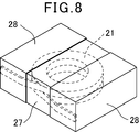
- a coil 21 is formed by winding a conductive wire on a conventional surface mount inductor, and this coil 21 is embedded in a molded body 27 formed of a sealing material containing magnetic powder and resin. There is one in which the coil 21 is connected to an external terminal 28 formed on the surface of the molded body 27 (see, for example, JP 2010-245473 A).
- this surface-mount inductor is configured such that a coil 21 formed by winding a conductive wire is placed on a tablet 22, and a lead-out end 21 b of the coil 21 is placed on a columnar protrusion of the tablet 22 as shown in FIG.
- the coil and the tablet are arranged in the molding die so as to be sandwiched between the inner wall surface of the molding die 24 along the outer side surface of the portion 22a.
- the molded object 27 which incorporates the coil 21 by the resin molding method or the compacting method is formed using this metal mold
- such a conventional surface-mount inductor is a molded body in which a coil is built in by a resin molding method or a powder molding method in a state where the lead end of the coil is sandwiched between the columnar convex portion of the tablet and the inner wall surface of the molding die. Since the shape of the tablet is complicated, the shape of the coil cannot be increased, and the area of the coil winding portion and the cross-sectional area of the conductive wire are reduced, resulting in poor superimposed current value Idc and resistance value Rdc. It was.
- An object of one or more embodiments of the present invention is to provide a surface-mount inductor that can improve the superimposed current value Idc and the resistance value Rdc and can be manufactured at low cost, and a manufacturing method thereof.
- a surface mount inductor including a coil formed by winding a conducting wire and a sealing material including a resin and a magnetic material, and including a molded body incorporating the coil. Is formed by winding a conducting wire so that the lead end is positioned on the outer periphery of the winding portion, and the molded body has a coil surface partially exposed on four side surfaces parallel to the coil winding axis. The area of the outer part of the winding part of the coil is formed so that the area of the part outside the outer periphery of the coil is substantially the same as or smaller than the area of the inner part of the coil winding part.
- one or more embodiments of the present invention use a coil formed by winding a conducting wire and a sealing material including a resin and a magnetic material, and a surface-mount inductor including a molded body incorporating the coil.
- a coil is formed by winding a conducting wire so that the leading end is positioned on the outer periphery of the winding part, and the coil is arranged between a pair of plate-like tablets formed using a sealing material
- the molded body Forming the molded body so that the area of the inner part of the winding part is substantially the same as or smaller than the area of the inner periphery of the winding part, and an external terminal connected to the lead-out end of the coil on the surface of the molded body Forming.
- a surface mount inductor including a coil formed by winding a conducting wire and a sealing material including a resin and a magnetic material, and including a molded body incorporating the coil. Is formed by winding a conducting wire so that the lead end is positioned on the outer periphery of the winding portion, and the molded body has a coil surface partially exposed on four side surfaces parallel to the coil winding axis.
- the area of the outer part of the outer periphery of the winding part of the coil is formed so that it is substantially the same as or smaller than the area of the inner part of the inner part of the winding part of the coil,
- the built-in coil can be enlarged, and the superimposed current value Idc and the resistance value Rdc can be improved.
- the structure of the tablet for forming the molded body can be simplified, and the tablet can be easily made.
- one or more embodiments of the present invention use a coil formed by winding a conducting wire and a sealing material including a resin and a magnetic material, and a surface-mount inductor including a molded body incorporating the coil.
- a coil is formed by winding a conducting wire so that the leading end is positioned on the outer periphery of the winding part, and the coil is arranged between a pair of plate-like tablets formed using a sealing material
- the coil is partially exposed on the four side surfaces parallel to the winding axis of the coil, and the area of the outer portion of the coil winding portion is smaller than the coil.
- FIG. 1 is a perspective view showing an embodiment of a surface mount inductor according to the present invention. It is a perspective view which shows arrangement
- One or more embodiments of the present invention include a molded body including a coil formed by winding a conductive wire and a coil formed using a sealing material including a resin and a magnetic material.
- the coil has a winding portion around which a conducting wire is wound so that both ends thereof are positioned on the outer periphery, and a lead-out end portion drawn from the outer periphery of the winding portion.
- the surface of the coil is partially exposed on four side surfaces parallel to the coil winding axis, and the area of the outer portion of the coil winding portion is larger than the inner periphery of the coil winding portion. It is formed so as to be substantially the same as or smaller than the area of the inner part.
- one or more embodiments of the present invention can increase the outer size of the coil to the maximum within the range of the outer size of the molded body, and thus reduce the dead space of the molded body. It is possible to increase the diameter of the winding axis of the coil and the cross-sectional area of the conducting wire.
- a coil is formed by winding a conducting wire such that the leading end is positioned on the outer periphery of the winding portion.
- the coil is arranged between a pair of plate-like tablets formed using a sealing material and having the same size as the outer circumference of the coil, and these are integrated using a resin molding method.
- the coil is partially exposed on four side surfaces parallel to the winding axis of the coil, and the area of the outer part of the coil winding part is substantially the same as the area of the inner part of the coil winding part.
- the molded body is formed to be the same or smaller.
- an external terminal connected to the coil drawing end is formed on the surface of the molded body. Therefore, the manufacturing method of the surface mount inductor according to the present invention can increase the outer size of the coil to the limit within the range of the outer size of the molded body, so that the dead space of the molded body can be reduced. It is possible to increase the diameter of the winding axis of the coil and the cross-sectional area of the conducting wire.
- FIG. 1 is a perspective view showing a state where a molded body of a surface mount inductor according to an embodiment of the present invention is seen through
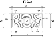
- FIG. 2 is a view where the inside of the molded body of a surface mounted inductor according to the present invention is seen through.
- 11 is a coil
- 17 is a molded body.
- the coil 11 includes a winding part 11a in which a conducting wire is wound in a spiral shape so that both ends thereof are positioned on the outer periphery, and a drawing end part 11b drawn from the winding part 11a.
- An air core coil is formed.
- the conducting wire is a rectangular wire having a rectangular cross section.
- the winding part 11a is formed in an elliptical shape.
- the lead-out end portion 11b is formed such that both ends of the conducting wire are drawn out from the winding portion 11a so as to face each other with the winding portion 11a interposed therebetween, and further bent in a direction opposite to the drawn-out direction.
- the molded body 17 is formed so as to incorporate the coil 11 using a sealing material including a resin and a magnetic material.
- a sealing material for example, an iron-based metal magnetic powder is used as a magnetic material, and an epoxy resin is used as a resin, and a mixture thereof is used.
- the size W1 of the molded body 17 in the width direction is formed to be approximately the same as the size W2 of the outer circumference in the minor axis direction of the winding portion 11a of the coil 11.
- the length L1 of the molded body 17 is such that the outer diameter L2 of the winding portion 11a of the coil 11 in the longitudinal direction, the thickness A of one of the leading ends 11b, and the thickness A of the other leading end 11b. It is approximately the same size as the sum of the thickness A or slightly larger.
- a part of the surface in the minor axis direction of the winding portion 11 a of the coil 11 is exposed on the opposite side surfaces of the molded body 17 in the width direction.
- the surface of the lead-out end portion 11 b of the coil 11 is exposed on the side surfaces of the molded body 17 facing in the length direction.
- the total area of the portions D1, D2, D3, D4 outside the outer peripheral surface of the winding part 11a of the coil 11 of the molded body 17 is the part inside the inner peripheral surface of the winding part 11a of the coil 11. It is formed to be substantially the same as S1 or smaller.
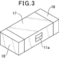
- a pair of external terminals 18 is formed on the surface of the molded body 17 as shown in FIG.
- the coil 11 is connected between the pair of external terminals 18 by connecting the drawn end portions 11 b of the coils 11 exposed on the opposite side surfaces in the length direction of the molded body 17 to the external terminals 18.
- Such a surface mount inductor is manufactured as follows. First, after forming a winding part by winding a conductive wire coated with a rectangular insulating coating in a spiral shape so that both ends thereof are positioned on the outer periphery, and then winding both ends of the conductive wire
- the air core coil is formed by being drawn from the outer periphery of the turning portion and further bent to form a lead end portion.
- the outer periphery of the coil 11 is used. Plate-shaped tablets 12 and 13 having approximately the same size are formed. Next, as shown in FIG.
- the winding part 11a and the leading end part 11b are The provided air-core coil is placed between the pair of plate-like tablets 12 and 13, and the punch 16 is set in the cavity of the molding die in this state.
- the air core coil 11 is built in by molding a pair of plate-like tablets and air core coils by a so-called resin molding method in which the mold is punched by a mold and a punch at 120 to 250 ° C. A molded body 17 is formed.
- the formed body 17 has a part of the surface in the short diameter direction of the winding portion 11a of the coil 11 on the side surface facing in the width direction, and the surface of the leading end portion 11b of the coil 11 on the side surface facing in the length direction.
- the area of the portion outside the outer peripheral surface of the winding portion 11a of the coil 11 is larger than the inner peripheral surface of the winding portion 11a of the coil 11. Is formed to be substantially the same as or smaller than the area of the inner portion.
- the molded body 17 formed in this way is subjected to a treatment for peeling off the insulating coating on the lead-out end portion 11b of the coil 11 exposed on the opposite side surfaces in the length direction and a barrel polishing treatment.
- the process of peeling off the insulating coating and the barrel polishing process can be performed simultaneously.
- an external terminal material containing a conductive material is applied to the surface of the molded body 17 and cured to form external terminals 18 on the surface of the molded body 17.
- the external terminal 18 may be plated with a material appropriately selected from one or more of Ni, Sn, Cu, Au, Pd and the like.
- the present invention is not limited to this embodiment.
- iron-based metal magnetic powder is used as the sealing material as the sealing material
- epoxy resin is used as the resin.
- the metal magnetic powder of another composition is used as the filling material, and the surface is coated with an insulator such as glass.
- Metal magnetic powder, metal magnetic powder with modified surface, ferrite powder, glass powder, etc. may be used.
- the resin a thermosetting resin such as a polyimide resin or a phenol resin, or a thermoplastic resin such as a polyethylene resin or a polyamide resin may be used.
- the coil may have a winding portion formed in a circular shape.
- the molded body has a coil placed on a plate-like tablet formed using a sealing material in a cavity of a molding die, and a powdery sealing material is filled on the coil, and these are resin molded.
- a compacting method to expose the surface in the short diameter direction of the coil winding portion on the surfaces of two opposite side surfaces in the width direction, and outside the outer periphery of the coil winding portion Is formed so that the area of the part of the coil is substantially the same as or smaller than the area of the inner part of the coil winding part, and the coil is drawn out on the surfaces of the two opposite side surfaces in the length direction.
- the surface of the end portion may be exposed.
Abstract
Since a molded body incorporating a coil is formed by a resin molding method or a pressure powder molding method with the leading ends of the coil sandwiched between a columnar projection of a tablet and an inner wall surface of a molding die, the shape of the tablet becomes complicated and the size of the coil cannot be increased, necessitating the reduction in the area of a winding axis section of the coil or in the sectional area of a conductive wire, and deterioration in the superimposed current value and the resistance value. The present invention provides a molded body incorporating a coil by using: a coil formed by winding a conductive wire; and a sealing member containing resin and magnetic material. The coil is formed by winding the conductive wire such that the leading ends thereof are positioned at the outer periphery of the winding. The molded body is formed such that the surface of the coil is partially exposed at four side surfaces of the molded body which are parallel to the winding axis of the coil and such that the area of a portion outside the outer periphery of the winding of the coil is substantially equal to or smaller than the area of a portion inside the inner periphery of the winding of the coil.
Description
本発明は、導線を巻回して形成したコイルと、樹脂と磁性材料を含む封止材を用いて形成されたコイルを内蔵する成形体とを備えた表面実装インダクタ及びその製造方法に関する。
The present invention relates to a surface mount inductor including a coil formed by winding a conductive wire, and a molded body containing a coil formed using a sealing material including a resin and a magnetic material, and a method for manufacturing the same.
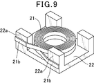
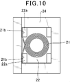
従来の表面実装インダクタに、図8に示す様に、導線を巻回してコイル21を形成し、このコイル21を磁性粉末と樹脂を含む封止材で形成された成形体27内に埋設し、コイル21を成形体27表面に形成された外部端子28に接続したものがある(例えば、特開2010-245473号公報を参照。)。この表面実装インダクタは、図9に示す様に、導線を巻回して形成したコイル21をタブレット22に載置し、図10に示す様に、コイル21の引き出し端部21bをタブレット22の柱状凸部22aの外側側面に沿わせて成型金型24の内壁面との間に挟まれるようにコイルとタブレットを成型金型に配置する。そして、この金型を用い、樹脂成形法もしくは圧粉成形法によりコイル21を内蔵する成形体27が形成される。
As shown in FIG. 8, a coil 21 is formed by winding a conductive wire on a conventional surface mount inductor, and this coil 21 is embedded in a molded body 27 formed of a sealing material containing magnetic powder and resin. There is one in which the coil 21 is connected to an external terminal 28 formed on the surface of the molded body 27 (see, for example, JP 2010-245473 A). As shown in FIG. 9, this surface-mount inductor is configured such that a coil 21 formed by winding a conductive wire is placed on a tablet 22, and a lead-out end 21 b of the coil 21 is placed on a columnar protrusion of the tablet 22 as shown in FIG. The coil and the tablet are arranged in the molding die so as to be sandwiched between the inner wall surface of the molding die 24 along the outer side surface of the portion 22a. And the molded object 27 which incorporates the coil 21 by the resin molding method or the compacting method is formed using this metal mold | die.
この様な従来の表面実装インダクタは、コイルが磁性材料入りの封止材で形成された成形体内に埋設されているので、コイル全体が磁性材料で被覆されることとなり、漏れ磁束を低減することができる。
この種の表面実装インダクタでは、小型化が望まれている上、高密度実装でない用途においては漏れ磁束よりも重畳電流値Idcや抵抗値Rdcが重視され、重畳電流値Idcが高く、抵抗値Rdcが低いものが望まれている。
しかしながら、この様な従来の表面実装インダクタは、コイルの引き出し端部をタブレットの柱状凸部と成型金型の内壁面に挟んだ状態で樹脂成形法もしくは圧粉成形法によりコイルを内蔵する成形体を形成しているため、タブレットの形状が複雑になると共に、コイルの形状を大きくできず、コイルの巻軸部分の面積や導線の断面積が小さくなって重畳電流値Idcや抵抗値Rdcが悪かった。 In such a conventional surface mount inductor, since the coil is embedded in a molded body formed of a sealing material containing a magnetic material, the entire coil is covered with the magnetic material, thereby reducing leakage magnetic flux. Can do.
In this type of surface-mount inductor, miniaturization is desired, and in applications where high-density mounting is not used, the superimposed current value Idc and the resistance value Rdc are more important than the leakage magnetic flux, the superimposed current value Idc is high, and the resistance value Rdc. A low value is desired.
However, such a conventional surface-mount inductor is a molded body in which a coil is built in by a resin molding method or a powder molding method in a state where the lead end of the coil is sandwiched between the columnar convex portion of the tablet and the inner wall surface of the molding die. Since the shape of the tablet is complicated, the shape of the coil cannot be increased, and the area of the coil winding portion and the cross-sectional area of the conductive wire are reduced, resulting in poor superimposed current value Idc and resistance value Rdc. It was.
本発明の一又はそれ以上の実施の形態は、重畳電流値Idcや抵抗値Rdcを改善でき、安価に製造できる表面実装インダクタ及びその製造方法を提供することを目的とする。
An object of one or more embodiments of the present invention is to provide a surface-mount inductor that can improve the superimposed current value Idc and the resistance value Rdc and can be manufactured at low cost, and a manufacturing method thereof.
本発明の一又はそれ以上の実施の形態は、導線を巻回して形成したコイルと、樹脂と磁性材料を含む封止材を用い、コイルを内蔵する成形体を備えた表面実装インダクタにおいて、コイルは、引き出し端部が巻回部の外周に位置する様に導線を巻回して形成され、成形体は、コイルの巻軸と平行な4つの側面にコイルの表面が部分的に露出し、コイルの巻回部の外周よりも外側の部分の面積がコイルの巻回部の内周よりも内側の部分の面積とほぼ同じか、それよりも小さくなる様に形成されている。
また、本発明の一又はそれ以上の実施の形態は、導線を巻回して形成したコイルと、樹脂と磁性材料を含む封止材を用い、コイルを内蔵する成形体を備えた表面実装インダクタの製造方法において、引き出し端部が巻回部の外周に位置する様に導線を巻回してコイルが形成される工程、封止材を用いて形成された1対の板状タブレット間にコイルを配置し、これらを樹脂成形法を用いて一体化させて、コイルの巻軸と平行な4つの側面にコイルが部分的に露出し、コイルの巻回部の外周よりも外側の部分の面積がコイルの巻回部の内周よりも内側の部分の面積とほぼ同じか、それよりも小さくなる様に成形体を形成する工程及び、成形体の表面にコイルの引き出し端部と接続する外部端子を形成する工程を備える。 In one or more embodiments of the present invention, a surface mount inductor including a coil formed by winding a conducting wire and a sealing material including a resin and a magnetic material, and including a molded body incorporating the coil. Is formed by winding a conducting wire so that the lead end is positioned on the outer periphery of the winding portion, and the molded body has a coil surface partially exposed on four side surfaces parallel to the coil winding axis. The area of the outer part of the winding part of the coil is formed so that the area of the part outside the outer periphery of the coil is substantially the same as or smaller than the area of the inner part of the coil winding part.
In addition, one or more embodiments of the present invention use a coil formed by winding a conducting wire and a sealing material including a resin and a magnetic material, and a surface-mount inductor including a molded body incorporating the coil. In the manufacturing method, a coil is formed by winding a conducting wire so that the leading end is positioned on the outer periphery of the winding part, and the coil is arranged between a pair of plate-like tablets formed using a sealing material These are integrated using a resin molding method, and the coil is partially exposed on the four side surfaces parallel to the winding axis of the coil, and the area of the outer portion of the coil winding portion is smaller than the coil. Forming the molded body so that the area of the inner part of the winding part is substantially the same as or smaller than the area of the inner periphery of the winding part, and an external terminal connected to the lead-out end of the coil on the surface of the molded body Forming.
本発明の一又はそれ以上の実施の形態は、導線を巻回して形成したコイルと、樹脂と磁性材料を含む封止材を用い、コイルを内蔵する成形体を備えた表面実装インダクタにおいて、コイルは、引き出し端部が巻回部の外周に位置する様に導線を巻回して形成され、成形体は、コイルの巻軸と平行な4つの側面にコイルの表面が部分的に露出し、コイルの巻回部の外周よりも外側の部分の面積がコイルの巻回部の内周よりも内側の部分の面積とほぼ同じか、それよりも小さくなる様に形成されているので、成形体に内蔵するコイルを大きくでき、重畳電流値Idcや抵抗値Rdcを改善することができる。また、成形体を形成するためのタブレットの構造を簡素化することができると共に、タブレットを作り易くすることができる。
また、本発明の一又はそれ以上の実施の形態は、導線を巻回して形成したコイルと、樹脂と磁性材料を含む封止材を用い、コイルを内蔵する成形体を備えた表面実装インダクタの製造方法において、引き出し端部が巻回部の外周に位置する様に導線を巻回してコイルが形成される工程、封止材を用いて形成された1対の板状タブレット間にコイルを配置し、これらを樹脂成形法を用いて一体化させて、コイルの巻軸と平行な4つの側面にコイルが部分的に露出し、コイルの巻回部の外周よりも外側の部分の面積がコイルの巻回部の内周よりも内側の部分の面積とほぼ同じか、それよりも小さくなる様に成形体を形成する工程及び、成形体の表面にコイルの引き出し端部と接続する外部端子を形成する工程を備えるので、製造工程を複雑にすることなく、成形体に内蔵するコイルを大きくでき、重畳電流値Idcや抵抗値Rdcを改善することができる。また、タブレットの構造を簡素化することができると共に、タブレットを作り易くすることができる。 In one or more embodiments of the present invention, a surface mount inductor including a coil formed by winding a conducting wire and a sealing material including a resin and a magnetic material, and including a molded body incorporating the coil. Is formed by winding a conducting wire so that the lead end is positioned on the outer periphery of the winding portion, and the molded body has a coil surface partially exposed on four side surfaces parallel to the coil winding axis. Since the area of the outer part of the outer periphery of the winding part of the coil is formed so that it is substantially the same as or smaller than the area of the inner part of the inner part of the winding part of the coil, The built-in coil can be enlarged, and the superimposed current value Idc and the resistance value Rdc can be improved. In addition, the structure of the tablet for forming the molded body can be simplified, and the tablet can be easily made.
In addition, one or more embodiments of the present invention use a coil formed by winding a conducting wire and a sealing material including a resin and a magnetic material, and a surface-mount inductor including a molded body incorporating the coil. In the manufacturing method, a coil is formed by winding a conducting wire so that the leading end is positioned on the outer periphery of the winding part, and the coil is arranged between a pair of plate-like tablets formed using a sealing material These are integrated using a resin molding method, and the coil is partially exposed on the four side surfaces parallel to the winding axis of the coil, and the area of the outer portion of the coil winding portion is smaller than the coil. Forming the molded body so that the area of the inner part of the winding part is substantially the same as or smaller than the area of the inner periphery of the winding part, and an external terminal connected to the lead-out end of the coil on the surface of the molded body Since it has a forming process, it complicates the manufacturing process. And without a coil incorporated in the shaped body can be increased, it is possible to improve the superimposed current value Idc and the resistance Rdc. In addition, the structure of the tablet can be simplified and the tablet can be made easily.
本発明の一又はそれ以上の実施の形態は、導線を巻回して形成したコイルと、樹脂と磁性材料を含む封止材を用いて形成されたコイルを内蔵する成形体を備える。コイルは、その両端が外周に位置する様に導線が巻回された巻回部と、巻回部の外周から引き出された引き出し端部を有する。成形体は、コイルの巻軸と平行な4つの側面にコイルの表面が部分的に露出し、コイルの巻回部の外周よりも外側の部分の面積がコイルの巻回部の内周よりも内側の部分の面積とほぼ同じか、それよりも小さくなる様に形成される。従って、本発明の一又はそれ以上の実施の形態は、コイルの外形の大きさを成形体の外形の大きさの範囲内で極限まで大きくすることができるので、成形体のデットスペースを小さくすることができ、コイルの巻軸部分の径や導線の断面積を大きくできる。
また、本発明の一又はそれ以上の実施の形態は、まず、引き出し端部が巻回部の外周に位置する様に導線を巻回してコイルが形成される。次に、封止材を用いてコイルの外周の大きさとほぼ同じ大きさに形成された1対の板状タブレット間にコイルを配置し、これらを樹脂成形法を用いて一体化させて、コイルの巻軸と平行な4つの側面にコイルが部分的に露出し、コイルの巻回部の外周よりも外側の部分の面積がコイルの巻回部の内周よりも内側の部分の面積とほぼ同じか、それよりも小さくなる様に成形体を形成する。最後に、成形体の表面にコイルの引き出し端部と接続する外部端子を形成する。従って、本発明の表面実装インダクタの製造方法は、コイルの外形の大きさを成形体の外形の大きさの範囲内で極限まで大きくすることができるので、成形体のデットスペースを小さくすることができ、コイルの巻軸部分の径や導線の断面積を大きくできる。 One or more embodiments of the present invention include a molded body including a coil formed by winding a conductive wire and a coil formed using a sealing material including a resin and a magnetic material. The coil has a winding portion around which a conducting wire is wound so that both ends thereof are positioned on the outer periphery, and a lead-out end portion drawn from the outer periphery of the winding portion. In the molded body, the surface of the coil is partially exposed on four side surfaces parallel to the coil winding axis, and the area of the outer portion of the coil winding portion is larger than the inner periphery of the coil winding portion. It is formed so as to be substantially the same as or smaller than the area of the inner part. Accordingly, one or more embodiments of the present invention can increase the outer size of the coil to the maximum within the range of the outer size of the molded body, and thus reduce the dead space of the molded body. It is possible to increase the diameter of the winding axis of the coil and the cross-sectional area of the conducting wire.
In one or more embodiments of the present invention, first, a coil is formed by winding a conducting wire such that the leading end is positioned on the outer periphery of the winding portion. Next, the coil is arranged between a pair of plate-like tablets formed using a sealing material and having the same size as the outer circumference of the coil, and these are integrated using a resin molding method. The coil is partially exposed on four side surfaces parallel to the winding axis of the coil, and the area of the outer part of the coil winding part is substantially the same as the area of the inner part of the coil winding part. The molded body is formed to be the same or smaller. Finally, an external terminal connected to the coil drawing end is formed on the surface of the molded body. Therefore, the manufacturing method of the surface mount inductor according to the present invention can increase the outer size of the coil to the limit within the range of the outer size of the molded body, so that the dead space of the molded body can be reduced. It is possible to increase the diameter of the winding axis of the coil and the cross-sectional area of the conducting wire.
以下、本発明を実施するための最良の形態について図1乃至図7を参照して説明する。
図1は本発明による表面実装インダクタの実施の形態の成形体の内部を透視した状態を示す斜視図、図2は本発明による表面実装インダクタの実施の形態の成形体の内部を透視した状態を示す断面図である。
図1、図2において、11はコイル、17は成形体である。
コイル11は、導線をその両端部が外周に位置するように渦巻き状に2段の外外巻きに巻回した巻回部11aと、巻回部11aから引き出された引き出し端部11bを備えた空芯コイルが形成される。導線は断面が平角状の平角線が用いられる。巻回部11aは楕円形に形成される。また、引き出し端部11bは、導線の両端部が巻回部11aから巻回部11aを挟んで対向する様に引き出され、さらに引き出された方向とは逆方向に折り曲げられて形成される。
成形体17は、樹脂と磁性材料を含む封止材を用いてコイル11を内蔵する様に形成される。封止材としては、磁性材料として例えば鉄系の金属磁性粉末を、樹脂として例えばエポキシ樹脂をそれぞれ用い、これらを混合したものが用いられる。この成形体17の幅方向の大きさW1は、コイル11の巻回部11aの短径方向の外周の大きさW2とほぼ同じ大きさに形成される。また、この成形体17の長さ方向の大きさL1は、コイル11の巻回部11aの長径方向の外周の大きさL2と一方の引き出し端部11bの厚みAと他方の引き出し端部11bの厚みAを足した大きさとほぼ同じ大きさか又は、少し大きく形成される。この成形体17の幅方向の対向する側面には、コイル11の巻回部11aの短径方向の表面の一部が露出する。また、成形体17の長さ方向の対向する側面には、コイル11の引き出し端部11bの表面が露出する。この時、成形体17のコイル11の巻回部11aの外周表面よりも外側の部分D1、D2、D3、D4の合計面積が、コイル11の巻回部11aの内周表面よりも内側の部分S1とほぼ同じか又は小さくなる様に形成される。この成形体17の表面には、図3に示す様に、1対の外部端子18が形成される。
そして、成形体17の長さ方向の対向する側面にそれぞれ露出したコイル11の引き出し端部11bが外部端子18に接続されることにより、コイル11が1対の外部端子18間に接続される。 Hereinafter, the best mode for carrying out the present invention will be described with reference to FIGS.
FIG. 1 is a perspective view showing a state where a molded body of a surface mount inductor according to an embodiment of the present invention is seen through, and FIG. 2 is a view where the inside of the molded body of a surface mounted inductor according to the present invention is seen through. It is sectional drawing shown.
1 and 2, 11 is a coil, and 17 is a molded body.
Thecoil 11 includes a winding part 11a in which a conducting wire is wound in a spiral shape so that both ends thereof are positioned on the outer periphery, and a drawing end part 11b drawn from the winding part 11a. An air core coil is formed. The conducting wire is a rectangular wire having a rectangular cross section. The winding part 11a is formed in an elliptical shape. The lead-out end portion 11b is formed such that both ends of the conducting wire are drawn out from the winding portion 11a so as to face each other with the winding portion 11a interposed therebetween, and further bent in a direction opposite to the drawn-out direction.
The moldedbody 17 is formed so as to incorporate the coil 11 using a sealing material including a resin and a magnetic material. As the sealing material, for example, an iron-based metal magnetic powder is used as a magnetic material, and an epoxy resin is used as a resin, and a mixture thereof is used. The size W1 of the molded body 17 in the width direction is formed to be approximately the same as the size W2 of the outer circumference in the minor axis direction of the winding portion 11a of the coil 11. Further, the length L1 of the molded body 17 is such that the outer diameter L2 of the winding portion 11a of the coil 11 in the longitudinal direction, the thickness A of one of the leading ends 11b, and the thickness A of the other leading end 11b. It is approximately the same size as the sum of the thickness A or slightly larger. A part of the surface in the minor axis direction of the winding portion 11 a of the coil 11 is exposed on the opposite side surfaces of the molded body 17 in the width direction. Further, the surface of the lead-out end portion 11 b of the coil 11 is exposed on the side surfaces of the molded body 17 facing in the length direction. At this time, the total area of the portions D1, D2, D3, D4 outside the outer peripheral surface of the winding part 11a of the coil 11 of the molded body 17 is the part inside the inner peripheral surface of the winding part 11a of the coil 11. It is formed to be substantially the same as S1 or smaller. A pair of external terminals 18 is formed on the surface of the molded body 17 as shown in FIG.
Thecoil 11 is connected between the pair of external terminals 18 by connecting the drawn end portions 11 b of the coils 11 exposed on the opposite side surfaces in the length direction of the molded body 17 to the external terminals 18.
図1は本発明による表面実装インダクタの実施の形態の成形体の内部を透視した状態を示す斜視図、図2は本発明による表面実装インダクタの実施の形態の成形体の内部を透視した状態を示す断面図である。
図1、図2において、11はコイル、17は成形体である。
コイル11は、導線をその両端部が外周に位置するように渦巻き状に2段の外外巻きに巻回した巻回部11aと、巻回部11aから引き出された引き出し端部11bを備えた空芯コイルが形成される。導線は断面が平角状の平角線が用いられる。巻回部11aは楕円形に形成される。また、引き出し端部11bは、導線の両端部が巻回部11aから巻回部11aを挟んで対向する様に引き出され、さらに引き出された方向とは逆方向に折り曲げられて形成される。
成形体17は、樹脂と磁性材料を含む封止材を用いてコイル11を内蔵する様に形成される。封止材としては、磁性材料として例えば鉄系の金属磁性粉末を、樹脂として例えばエポキシ樹脂をそれぞれ用い、これらを混合したものが用いられる。この成形体17の幅方向の大きさW1は、コイル11の巻回部11aの短径方向の外周の大きさW2とほぼ同じ大きさに形成される。また、この成形体17の長さ方向の大きさL1は、コイル11の巻回部11aの長径方向の外周の大きさL2と一方の引き出し端部11bの厚みAと他方の引き出し端部11bの厚みAを足した大きさとほぼ同じ大きさか又は、少し大きく形成される。この成形体17の幅方向の対向する側面には、コイル11の巻回部11aの短径方向の表面の一部が露出する。また、成形体17の長さ方向の対向する側面には、コイル11の引き出し端部11bの表面が露出する。この時、成形体17のコイル11の巻回部11aの外周表面よりも外側の部分D1、D2、D3、D4の合計面積が、コイル11の巻回部11aの内周表面よりも内側の部分S1とほぼ同じか又は小さくなる様に形成される。この成形体17の表面には、図3に示す様に、1対の外部端子18が形成される。
そして、成形体17の長さ方向の対向する側面にそれぞれ露出したコイル11の引き出し端部11bが外部端子18に接続されることにより、コイル11が1対の外部端子18間に接続される。 Hereinafter, the best mode for carrying out the present invention will be described with reference to FIGS.
FIG. 1 is a perspective view showing a state where a molded body of a surface mount inductor according to an embodiment of the present invention is seen through, and FIG. 2 is a view where the inside of the molded body of a surface mounted inductor according to the present invention is seen through. It is sectional drawing shown.
1 and 2, 11 is a coil, and 17 is a molded body.
The
The molded
The
この様な表面実装インダクタは以下の様にして製造される。まず、断面が平角状の絶縁被覆が施された導線をその両端が外周に位置する様に渦巻き状に2段の外外巻きに巻回して巻回部を形成した後、導線の両端が巻回部の外周から引き出され、さらに折り曲げ加工を施して引き出し端部を形成して空芯コイルが形成される。
また、後述の様に巻回部11aと引き出し端部11bを備えた空芯コイル11を内蔵する成形体を形成するために、封止材を用いて図4に示す様にコイル11の外周の大きさとほぼ同じ大きさの板状タブレット12、13が形成される。
次に、図5に示す様に、割型14aと割型14bを備える上型14と下型(図示せず)とでキャビティを形成する成型金型のキャビティ内に、板状タブレット12上に搭載された状態で巻回部11aと引き出し端部11bを備えた空芯コイルを収納する。
続いて、巻回部11aと引き出し端部11bを備えた空芯コイルと板状タブレット12が収納された成型金型のキャビティ内に、板状タブレット13が空芯コイル上に位置する様に収納される。これにより、図6に示す様に、割型14aと割型14bを備える上型14と下型15とでキャビティを形成する成型金型のキャビティ内において、巻回部11aと引き出し端部11bを備えた空芯コイルが1対の板状タブレット12、13間に配置された状態となり、この状態で成型金型のキャビティにパンチ16がセットされる。
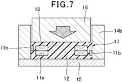
さらに、図7に示す様に、1対の板状タブレットと空芯コイルを成型金型とパンチによって120~250℃で圧縮するいわゆる樹脂成形法で成型することにより、空芯コイル11を内蔵した成形体17が形成される。この成形体17は、幅方向の対向する側面にコイル11の巻回部11aの短径方向の表面の一部が、長さ方向の対向する側面にコイル11の引き出し端部11bの表面がそれぞれ露出し、成形体17をコイル11の巻軸方向から透視した場合における、コイル11の巻回部11aの外周表面よりも外側の部分の面積が、コイル11の巻回部11aの内周表面よりも内側の部分の面積とほぼ同じか、又は、それよりも小さくなる様に形成される。
この様に形成された成形体17は、長さ方向の対向する側面に露出したコイル11の引き出し端部11bの絶縁被覆を剥離する処理と、バレル研磨処理が施される。この絶縁被覆を剥離する処理と、バレル研磨処理は、同時に行うこともできる。
そして、再度図3を参照して、この成形体17の表面に導電材を含有する外部端子材料を塗布し、硬化させて成形体17の表面に外部端子18が形成される。この外部端子18は、Ni、Sn、Cu、Au、Pd等から1つもしくは複数を適宜選択した材料でメッキを施してもよい。 Such a surface mount inductor is manufactured as follows. First, after forming a winding part by winding a conductive wire coated with a rectangular insulating coating in a spiral shape so that both ends thereof are positioned on the outer periphery, and then winding both ends of the conductive wire The air core coil is formed by being drawn from the outer periphery of the turning portion and further bent to form a lead end portion.
Moreover, in order to form the molded object which incorporates theair core coil 11 provided with the winding part 11a and the drawer | drawing-out end part 11b as mentioned later, as shown in FIG. 4, the outer periphery of the coil 11 is used. Plate-shaped tablets 12 and 13 having approximately the same size are formed.
Next, as shown in FIG. 5, on the plate-like tablet 12 in the cavity of a molding die that forms a cavity with an upper mold 14 and a lower mold (not shown) having a split mold 14 a and a split mold 14 b. The air-core coil provided with the winding part 11a and the lead-out end part 11b is accommodated in the mounted state.
Subsequently, the plate-like tablet 13 is accommodated in the cavity of the molding die in which the air-core coil having the winding portion 11a and the lead-out end portion 11b and the plate-like tablet 12 are accommodated. Is done. Thereby, as shown in FIG. 6, in the cavity of the molding die which forms a cavity with the upper mold 14 and the lower mold 15 provided with the split mold 14a and the split mold 14b, the winding part 11a and the leading end part 11b are The provided air-core coil is placed between the pair of plate- like tablets 12 and 13, and the punch 16 is set in the cavity of the molding die in this state.
Further, as shown in FIG. 7, theair core coil 11 is built in by molding a pair of plate-like tablets and air core coils by a so-called resin molding method in which the mold is punched by a mold and a punch at 120 to 250 ° C. A molded body 17 is formed. The formed body 17 has a part of the surface in the short diameter direction of the winding portion 11a of the coil 11 on the side surface facing in the width direction, and the surface of the leading end portion 11b of the coil 11 on the side surface facing in the length direction. When the molded body 17 is exposed and seen through from the winding axis direction of the coil 11, the area of the portion outside the outer peripheral surface of the winding portion 11a of the coil 11 is larger than the inner peripheral surface of the winding portion 11a of the coil 11. Is formed to be substantially the same as or smaller than the area of the inner portion.
The moldedbody 17 formed in this way is subjected to a treatment for peeling off the insulating coating on the lead-out end portion 11b of the coil 11 exposed on the opposite side surfaces in the length direction and a barrel polishing treatment. The process of peeling off the insulating coating and the barrel polishing process can be performed simultaneously.
Then, referring again to FIG. 3, an external terminal material containing a conductive material is applied to the surface of the moldedbody 17 and cured to form external terminals 18 on the surface of the molded body 17. The external terminal 18 may be plated with a material appropriately selected from one or more of Ni, Sn, Cu, Au, Pd and the like.
また、後述の様に巻回部11aと引き出し端部11bを備えた空芯コイル11を内蔵する成形体を形成するために、封止材を用いて図4に示す様にコイル11の外周の大きさとほぼ同じ大きさの板状タブレット12、13が形成される。
次に、図5に示す様に、割型14aと割型14bを備える上型14と下型(図示せず)とでキャビティを形成する成型金型のキャビティ内に、板状タブレット12上に搭載された状態で巻回部11aと引き出し端部11bを備えた空芯コイルを収納する。
続いて、巻回部11aと引き出し端部11bを備えた空芯コイルと板状タブレット12が収納された成型金型のキャビティ内に、板状タブレット13が空芯コイル上に位置する様に収納される。これにより、図6に示す様に、割型14aと割型14bを備える上型14と下型15とでキャビティを形成する成型金型のキャビティ内において、巻回部11aと引き出し端部11bを備えた空芯コイルが1対の板状タブレット12、13間に配置された状態となり、この状態で成型金型のキャビティにパンチ16がセットされる。
さらに、図7に示す様に、1対の板状タブレットと空芯コイルを成型金型とパンチによって120~250℃で圧縮するいわゆる樹脂成形法で成型することにより、空芯コイル11を内蔵した成形体17が形成される。この成形体17は、幅方向の対向する側面にコイル11の巻回部11aの短径方向の表面の一部が、長さ方向の対向する側面にコイル11の引き出し端部11bの表面がそれぞれ露出し、成形体17をコイル11の巻軸方向から透視した場合における、コイル11の巻回部11aの外周表面よりも外側の部分の面積が、コイル11の巻回部11aの内周表面よりも内側の部分の面積とほぼ同じか、又は、それよりも小さくなる様に形成される。
この様に形成された成形体17は、長さ方向の対向する側面に露出したコイル11の引き出し端部11bの絶縁被覆を剥離する処理と、バレル研磨処理が施される。この絶縁被覆を剥離する処理と、バレル研磨処理は、同時に行うこともできる。
そして、再度図3を参照して、この成形体17の表面に導電材を含有する外部端子材料を塗布し、硬化させて成形体17の表面に外部端子18が形成される。この外部端子18は、Ni、Sn、Cu、Au、Pd等から1つもしくは複数を適宜選択した材料でメッキを施してもよい。 Such a surface mount inductor is manufactured as follows. First, after forming a winding part by winding a conductive wire coated with a rectangular insulating coating in a spiral shape so that both ends thereof are positioned on the outer periphery, and then winding both ends of the conductive wire The air core coil is formed by being drawn from the outer periphery of the turning portion and further bent to form a lead end portion.
Moreover, in order to form the molded object which incorporates the
Next, as shown in FIG. 5, on the plate-
Subsequently, the plate-
Further, as shown in FIG. 7, the
The molded
Then, referring again to FIG. 3, an external terminal material containing a conductive material is applied to the surface of the molded
以上、本発明の表面実装インダクタ及びその製造方法の実施の形態を述べたが、本発明はこの実施の形態に限られるものではない。例えば、実施の形態では封止材として充填物に鉄系金属磁性粉末、樹脂にエポキシ樹脂を用いたが、充填物として他の組成の金属磁性粉末、その表面がガラス等の絶縁体で被覆された金属磁性粉末、表面を改質した金属磁性粉末、フェライト粉末、ガラス粉末等を用いても良い。また、樹脂として、ポリイミド樹脂やフェノール樹脂などの熱硬化性樹脂や、ポリエチレン樹脂やポリアミド樹脂などの熱可塑性樹脂を用いても良い。さらに、コイルは、巻回部が円形に形成されても良い。またさらに、成形体は、成型金型のキャビティ内において封止材を用いて形成された板状タブレット上にコイルを配置し、コイル上に粉末状の封止材を充填し、これらを樹脂成形法もしくは圧粉成形法を用いて一体化させて、幅方向の対向する2つの側面の表面にコイルの巻回部の短径方向の表面を露出させ、コイルの巻回部の外周よりも外側の部分の面積がコイルの巻回部の内周よりも内側の部分の面積とほぼ同じか、それよりも小さくなる様に形成され、長さ方向の対向する2つの側面の表面にコイルの引き出し端部の表面を露出させて形成しても良い。
The embodiment of the surface mount inductor and the manufacturing method thereof according to the present invention has been described above, but the present invention is not limited to this embodiment. For example, in the embodiment, iron-based metal magnetic powder is used as the sealing material as the sealing material, and epoxy resin is used as the resin. However, the metal magnetic powder of another composition is used as the filling material, and the surface is coated with an insulator such as glass. Metal magnetic powder, metal magnetic powder with modified surface, ferrite powder, glass powder, etc. may be used. Further, as the resin, a thermosetting resin such as a polyimide resin or a phenol resin, or a thermoplastic resin such as a polyethylene resin or a polyamide resin may be used. Furthermore, the coil may have a winding portion formed in a circular shape. Still further, the molded body has a coil placed on a plate-like tablet formed using a sealing material in a cavity of a molding die, and a powdery sealing material is filled on the coil, and these are resin molded. Or by using a compacting method to expose the surface in the short diameter direction of the coil winding portion on the surfaces of two opposite side surfaces in the width direction, and outside the outer periphery of the coil winding portion Is formed so that the area of the part of the coil is substantially the same as or smaller than the area of the inner part of the coil winding part, and the coil is drawn out on the surfaces of the two opposite side surfaces in the length direction. The surface of the end portion may be exposed.
11 コイル
17 成形体 11Coil 17 Molded body
17 成形体 11
Claims (6)
- 導線を巻回して形成したコイルと、樹脂と磁性材料を含む封止材を用い、該コイルを内蔵する成形体を備えた表面実装インダクタにおいて、
該コイルは、引き出し端部が巻回部の外周に位置する様に導線を巻回して形成され、
該成形体は、該コイルの巻軸と平行な4つの側面に該コイルの表面が部分的に露出し、該コイルの巻回部の外周よりも外側の部分の面積が該コイルの巻回部の内周よりも内側の部分の面積とほぼ同じか、それよりも小さくなる様に形成されていることを特徴とする表面実装インダクタ。 In a surface mount inductor including a coil formed by winding a conductive wire and a sealing material including a resin and a magnetic material, and a molded body incorporating the coil,
The coil is formed by winding a conducting wire so that the leading end is located on the outer periphery of the winding part,
In the molded body, the surface of the coil is partially exposed on four side surfaces parallel to the winding axis of the coil, and the area of the portion outside the outer periphery of the coil winding portion is the winding portion of the coil. A surface mount inductor characterized in that it is formed so as to be substantially the same as or smaller than the area of the inner part of the inner periphery of. - 前記コイルは、その両端が外周に位置する様に導線が巻回された巻回部と、該巻回部の外周から引き出された引き出し端部を有する請求項1に記載の表面実装インダクタ。 2. The surface mount inductor according to claim 1, wherein the coil has a winding portion around which a conducting wire is wound so that both ends thereof are positioned on the outer periphery, and a drawn end portion drawn from the outer periphery of the winding portion.
- 前記コイルは、その両端が外周に位置する様に導線を巻回して楕円形に形成された巻回部と、該巻回部の外周から引き出された引き出し端部を有し、該巻回部の短径方向の大きさと前記成形体の幅方向の大きさを同じにし、該巻回部の長径方向の大きさを、前記成形体の長さ方向の大きさから導線2本分の大きさを引いた大きさ以下にし、
前記成形体は、幅方向の対向する2つの側面の表面に該コイルの巻回部の短径方向の表面を露出させ、長さ方向の対向する2つの側面の表面に該コイルの引き出し端部の表面を露出させて、該コイルの引き出し端部を外部端子に接続した請求項1に記載の表面実装インダクタ。 The coil has a winding portion that is formed in an elliptical shape by winding a conducting wire so that both ends thereof are positioned on the outer periphery, and a drawn end portion that is drawn out from the outer periphery of the winding portion. The size in the minor axis direction is the same as the size in the width direction of the molded body, and the size in the major axis direction of the wound portion is the size of two conductors from the length in the length direction of the molded body. Less than the size minus
The molded body exposes the surface of the winding portion of the coil in the short diameter direction on the surfaces of the two side surfaces facing each other in the width direction, and the drawing end portion of the coil on the surfaces of the two side surfaces facing each other in the length direction The surface mount inductor according to claim 1, wherein a surface of the coil is exposed and a lead end portion of the coil is connected to an external terminal. - 導線を巻回して形成したコイルと、樹脂と磁性材料を含む封止材を用い、該コイルを内蔵する成形体を備えた表面実装インダクタの製造方法において、
引き出し端部が巻回部の外周に位置する様に導線を巻回してコイルが形成される工程、
該封止材を用いて形成された1対の板状タブレット間に該コイルを配置し、これらを樹脂成形法を用いて一体化させて、該コイルの巻軸と平行な4つの側面に該コイルが部分的に露出し、該コイルの巻回部の外周よりも外側の部分の面積が該コイルの巻回部の内周よりも内側の部分の面積とほぼ同じか、それよりも小さくなる様に成形体を形成する工程及び、
該成形体の表面に該コイルの引き出し端部と接続する外部端子を形成する工程を備えたことを特徴とする表面実装インダクタの製造方法。 In a method of manufacturing a surface-mount inductor using a coil formed by winding a conductive wire and a sealing material containing a resin and a magnetic material, and a molded body incorporating the coil,
A step in which a coil is formed by winding a conducting wire so that the leading end is positioned on the outer periphery of the winding portion;
The coil is arranged between a pair of plate-like tablets formed using the sealing material, and these are integrated using a resin molding method, and the four side surfaces parallel to the winding axis of the coil are The coil is partially exposed, and the area of the portion outside the outer periphery of the coil winding portion is substantially the same as or smaller than the area of the inner portion of the coil winding portion. A step of forming a molded body like
A method for manufacturing a surface-mount inductor, comprising: forming an external terminal connected to a lead-out end portion of the coil on a surface of the molded body. - 前記コイルが形成される工程において、その両端が外周に位置する様に導線を巻回して楕円形に形成された巻回部と、該巻回部の外周から引き出された引き出し端部を有し、該巻回部の短径方向の大きさと前記成形体の幅方向の大きさを同じにし、該巻回部の長径方向の大きさを、前記成形体の長さ方向の大きさから導線2本分の大きさを引いた大きさ以下にしたコイルが形成され、
前記成形体を形成する工程において、幅方向の対向する2つの側面の表面に該コイルの巻回部の短径方向の表面を露出させ、長さ方向の対向する2つの側面の表面に該コイルの引き出し端部の表面を露出させて成形体が形成された請求項4に記載の表面実装インダクタの製造方法。 In the step of forming the coil, it has a winding portion that is formed in an elliptical shape by winding a conducting wire so that both ends thereof are positioned on the outer periphery, and a drawing end portion that is drawn out from the outer periphery of the winding portion. The size of the wound portion in the minor axis direction is the same as the size of the molded body in the width direction, and the length of the wound portion in the major axis direction is determined from the length of the molded body in the length direction. A coil with a size less than the size of this is formed,
In the step of forming the molded body, the surface in the short diameter direction of the winding portion of the coil is exposed on the surfaces of the two side surfaces facing in the width direction, and the coil is formed on the surfaces of the two side surfaces facing in the length direction. The method for manufacturing a surface-mount inductor according to claim 4, wherein the molded body is formed by exposing a surface of the lead end portion. - 導線を巻回して形成したコイルと、樹脂と磁性材料を含む封止材を用い、該コイルを内蔵する成形体を備えた表面実装インダクタの製造方法において、
その両端が外周に位置する様に導線を巻回して楕円形に形成された巻回部と、該巻回部の外周から引き出された引き出し端部を有し、該巻回部の短径方向の大きさと該成形体の幅方向の大きさを同じにし、該巻回部の長径方向の大きさを、該成形体の長さ方向の大きさから導線2本分の大きさを引いた大きさ以下にしたコイルが形成される工程、
成型金型のキャビティ内において該封止材を用いて形成された板状タブレット上に該コイルを配置し、該コイル上に該封止材を充填し、これらを樹脂成形法もしくは圧粉成形法を用いて一体化させて、幅方向の対向する2つの側面の表面に該コイルの巻回部の短径方向の表面を露出させ、該コイルの巻回部の外周よりも外側の部分の面積が該コイルの巻回部の内周よりも内側の部分の面積とほぼ同じか、それよりも小さくなる様に形成され、長さ方向の対向する2つの側面の表面に該コイルの引き出し端部の表面を露出させた成形体を形成する工程及び、
該成形体の表面に該コイルの引き出し端部と接続する外部端子を形成する工程を備えたことを特徴とする表面実装インダクタの製造方法。 In a method of manufacturing a surface-mount inductor using a coil formed by winding a conductive wire and a sealing material containing a resin and a magnetic material, and a molded body incorporating the coil,
A winding portion that is formed in an elliptical shape by winding a conducting wire so that both ends thereof are located on the outer periphery, and a drawing end portion that is drawn out from the outer periphery of the winding portion, and the minor axis direction of the winding portion And the size in the width direction of the molded body are the same, and the size in the major axis direction of the wound portion is obtained by subtracting the size of the two conductors from the size in the length direction of the molded body. A step of forming a coil having a thickness of
The coil is disposed on a plate-like tablet formed using the sealing material in the cavity of the molding die, and the sealing material is filled on the coil, and these are molded by a resin molding method or a powder molding method. Are used to expose the surface of the winding portion of the coil in the short diameter direction on the surfaces of the two opposite side surfaces in the width direction, and the area of the portion outside the outer periphery of the winding portion of the coil Is formed to be substantially the same as or smaller than the area of the inner part of the inner periphery of the winding portion of the coil, and the lead-out ends of the coil are formed on the surfaces of the two opposite side surfaces in the length direction. Forming a molded body exposing the surface of
A method for manufacturing a surface-mount inductor, comprising: forming an external terminal connected to a lead-out end portion of the coil on a surface of the molded body.
Priority Applications (4)
| Application Number | Priority Date | Filing Date | Title |
|---|---|---|---|
| KR1020177001313A KR101866150B1 (en) | 2014-07-18 | 2015-07-07 | Surface-mounted inductor and manufacturing method therefor |
| CN201580039109.9A CN106575563B (en) | 2014-07-18 | 2015-07-07 | Surface mounting inductor and its manufacturing method |
| US15/407,727 US10847309B2 (en) | 2014-07-18 | 2017-01-17 | Surface mounted inductor and manufacturing method therefor |
| US17/074,168 US11908611B2 (en) | 2014-07-18 | 2020-10-19 | Manufacturing method for surface mounted inductor |
Applications Claiming Priority (2)
| Application Number | Priority Date | Filing Date | Title |
|---|---|---|---|
| JP2014147486A JP6060116B2 (en) | 2014-07-18 | 2014-07-18 | Surface mount inductor and manufacturing method thereof |
| JP2014-147486 | 2014-07-18 |
Related Child Applications (1)
| Application Number | Title | Priority Date | Filing Date |
|---|---|---|---|
| US15/407,727 Continuation US10847309B2 (en) | 2014-07-18 | 2017-01-17 | Surface mounted inductor and manufacturing method therefor |
Publications (1)
| Publication Number | Publication Date |
|---|---|
| WO2016009899A1 true WO2016009899A1 (en) | 2016-01-21 |
Family
ID=55078395
Family Applications (1)
| Application Number | Title | Priority Date | Filing Date |
|---|---|---|---|
| PCT/JP2015/069526 WO2016009899A1 (en) | 2014-07-18 | 2015-07-07 | Surface-mounted inductor and manufacturing method therefor |
Country Status (5)
| Country | Link |
|---|---|
| US (2) | US10847309B2 (en) |
| JP (1) | JP6060116B2 (en) |
| KR (1) | KR101866150B1 (en) |
| CN (1) | CN106575563B (en) |
| WO (1) | WO2016009899A1 (en) |
Cited By (2)
| Publication number | Priority date | Publication date | Assignee | Title |
|---|---|---|---|---|
| KR101792389B1 (en) | 2016-01-29 | 2017-11-20 | 삼성전기주식회사 | Coil electronic component |
| CN113972048A (en) * | 2021-10-29 | 2022-01-25 | 深圳市斯比特电子有限公司 | Fast assembling type magnetic integrated device |
Families Citing this family (18)
| Publication number | Priority date | Publication date | Assignee | Title |
|---|---|---|---|---|
| JP6341138B2 (en) * | 2015-04-10 | 2018-06-13 | 株式会社村田製作所 | Surface mount inductor and manufacturing method thereof |
| JP6388015B2 (en) * | 2016-11-17 | 2018-09-12 | Tdk株式会社 | Coil parts and coil equipment |
| JP2018182209A (en) * | 2017-04-19 | 2018-11-15 | 株式会社村田製作所 | Coil component |
| CN107359045B (en) * | 2017-07-17 | 2022-03-25 | 广州市精程达精密机械有限公司 | Bent angle forming machine |
| KR102484848B1 (en) * | 2017-09-20 | 2023-01-05 | 삼성전기주식회사 | Chip electronic component |
| JP7372747B2 (en) * | 2018-03-16 | 2023-11-01 | 日東電工株式会社 | Wired circuit board and its manufacturing method |
| WO2019239671A1 (en) * | 2018-06-15 | 2019-12-19 | アルプスアルパイン株式会社 | Coil-embedded molded powder core, inductance element, and electronic/electrical device |
| JP6922871B2 (en) * | 2018-09-28 | 2021-08-18 | 株式会社村田製作所 | Inductor parts and how to manufacture inductor parts |
| JP2020077795A (en) * | 2018-11-08 | 2020-05-21 | 株式会社村田製作所 | Surface mount inductor |
| KR102176279B1 (en) | 2019-05-03 | 2020-11-09 | 삼성전기주식회사 | Coil electronic component |
| JP7373930B2 (en) * | 2019-06-28 | 2023-11-06 | 太陽誘電株式会社 | laminated coil parts |
| US20210035730A1 (en) * | 2019-07-31 | 2021-02-04 | Murata Manufacturing Co., Ltd. | Inductor |
| CN110718359A (en) * | 2019-11-08 | 2020-01-21 | 汕头市信技电子科技有限公司 | Manufacturing structure and method of surface-mounted integrally-formed inductor |
| JP7456239B2 (en) | 2020-03-31 | 2024-03-27 | 株式会社村田製作所 | inductor |
| JP7279688B2 (en) * | 2020-06-08 | 2023-05-23 | 株式会社村田製作所 | inductor |
| KR102414826B1 (en) * | 2020-06-18 | 2022-06-30 | 삼성전기주식회사 | Coil component |
| CN112382479B (en) * | 2020-10-21 | 2022-09-23 | 惠州市明大精密电子有限公司 | I-shaped inductor and manufacturing method thereof |
| CN113470966B (en) * | 2021-07-15 | 2022-05-20 | 合泰盟方电子(深圳)股份有限公司 | Inductor forming system and forming process |
Citations (2)
| Publication number | Priority date | Publication date | Assignee | Title |
|---|---|---|---|---|
| JP2010283119A (en) * | 2009-06-04 | 2010-12-16 | Denso Corp | Reactor |
| JP2014049597A (en) * | 2012-08-31 | 2014-03-17 | Toko Inc | Surface mounting inductor and manufacturing method therefor |
Family Cites Families (9)
| Publication number | Priority date | Publication date | Assignee | Title |
|---|---|---|---|---|
| JP3201309B2 (en) * | 1997-05-23 | 2001-08-20 | 株式会社村田製作所 | Laminated coil and method of manufacturing the same |
| JP4933830B2 (en) * | 2006-05-09 | 2012-05-16 | スミダコーポレーション株式会社 | Inductor |
| JP2008124162A (en) * | 2006-11-10 | 2008-05-29 | Toko Inc | Low height chip coil, and its manufacturing method |
| JP4714779B2 (en) * | 2009-04-10 | 2011-06-29 | 東光株式会社 | Manufacturing method of surface mount inductor and surface mount inductor |
| JP2012160507A (en) * | 2011-01-31 | 2012-08-23 | Toko Inc | Surface mount inductor and method for manufacturing surface mount inductor |
| JP2013110184A (en) * | 2011-11-18 | 2013-06-06 | Toko Inc | Surface-mounted inductor manufacturing method and surface-mounted inductor |
| JP5623446B2 (en) * | 2012-03-02 | 2014-11-12 | 東光株式会社 | Manufacturing method of surface mount inductor |
| KR101771731B1 (en) * | 2012-08-28 | 2017-08-25 | 삼성전기주식회사 | Multi-layered chip electronic component |
| JP5894119B2 (en) * | 2013-06-14 | 2016-03-23 | 東光株式会社 | Manufacturing method of surface mount inductor |
-
2014
- 2014-07-18 JP JP2014147486A patent/JP6060116B2/en active Active
-
2015
- 2015-07-07 KR KR1020177001313A patent/KR101866150B1/en active IP Right Grant
- 2015-07-07 WO PCT/JP2015/069526 patent/WO2016009899A1/en active Application Filing
- 2015-07-07 CN CN201580039109.9A patent/CN106575563B/en active Active
-
2017
- 2017-01-17 US US15/407,727 patent/US10847309B2/en active Active
-
2020
- 2020-10-19 US US17/074,168 patent/US11908611B2/en active Active
Patent Citations (2)
| Publication number | Priority date | Publication date | Assignee | Title |
|---|---|---|---|---|
| JP2010283119A (en) * | 2009-06-04 | 2010-12-16 | Denso Corp | Reactor |
| JP2014049597A (en) * | 2012-08-31 | 2014-03-17 | Toko Inc | Surface mounting inductor and manufacturing method therefor |
Cited By (3)
| Publication number | Priority date | Publication date | Assignee | Title |
|---|---|---|---|---|
| KR101792389B1 (en) | 2016-01-29 | 2017-11-20 | 삼성전기주식회사 | Coil electronic component |
| CN113972048A (en) * | 2021-10-29 | 2022-01-25 | 深圳市斯比特电子有限公司 | Fast assembling type magnetic integrated device |
| CN113972048B (en) * | 2021-10-29 | 2022-05-17 | 深圳市斯比特电子有限公司 | Fast assembling type magnetic integrated device |
Also Published As
| Publication number | Publication date |
|---|---|
| CN106575563B (en) | 2018-10-26 |
| KR101866150B1 (en) | 2018-06-08 |
| KR20170019439A (en) | 2017-02-21 |
| CN106575563A (en) | 2017-04-19 |
| US20170125158A1 (en) | 2017-05-04 |
| US20210035731A1 (en) | 2021-02-04 |
| US10847309B2 (en) | 2020-11-24 |
| JP6060116B2 (en) | 2017-01-11 |
| US11908611B2 (en) | 2024-02-20 |
| JP2016025180A (en) | 2016-02-08 |
Similar Documents
| Publication | Publication Date | Title |
|---|---|---|
| WO2016009899A1 (en) | Surface-mounted inductor and manufacturing method therefor | |
| TWI581277B (en) | Surface mount inductor and method for making surface mount inductor | |
| KR102046344B1 (en) | Surface-mount inductor and production method thereof | |
| JP6763295B2 (en) | Surface mount inductor | |
| WO2016035861A1 (en) | Surface-mounted inductor and method for manufacturing same | |
| JP2015115406A (en) | Common mode choke coil and manufacturing method therefor | |
| JP2013098282A (en) | Plane mounting inductor | |
| WO2013018755A1 (en) | Coil part and method for manufacturing same | |
| JP2020077794A (en) | Surface mount inductor | |
| JP5450566B2 (en) | Manufacturing method of surface mount inductor | |
| JP2020077795A (en) | Surface mount inductor | |
| JP2016162801A (en) | Surface-mounted inductor and method of manufacturing the same | |
| KR20150139267A (en) | Wire wound inductor | |
| JP6332159B2 (en) | Surface mount inductor and manufacturing method thereof | |
| WO2016035862A1 (en) | Surface mount inductor and method for manufacturing same | |
| KR20160134633A (en) | Wire wound inductor and manufacturing method thereof | |
| WO2017070832A1 (en) | Surface-mounted inductor and manufacturing method therefor | |
| JP6379468B2 (en) | Wire wound electronic components | |
| KR102310477B1 (en) | Inductor and producing method of the same | |
| JP2020077790A (en) | Surface mount inductor | |
| JP2016025150A (en) | Toroidal coil | |
| KR101130790B1 (en) | Electric transformer and manufacturing method therefor | |
| JP6332160B2 (en) | Surface mount inductor and manufacturing method thereof | |
| JP6206164B2 (en) | Surface mount inductor | |
| JP2015201537A (en) | Coil component and manufacturing method for the same |
Legal Events
| Date | Code | Title | Description |
|---|---|---|---|
| 121 | Ep: the epo has been informed by wipo that ep was designated in this application |
Ref document number: 15821836 Country of ref document: EP Kind code of ref document: A1 |
|
| ENP | Entry into the national phase |
Ref document number: 20177001313 Country of ref document: KR Kind code of ref document: A |
|
| NENP | Non-entry into the national phase |
Ref country code: DE |
|
| 122 | Ep: pct application non-entry in european phase |
Ref document number: 15821836 Country of ref document: EP Kind code of ref document: A1 |