WO2016002947A1 - 光ファイバレーザ装置 - Google Patents
光ファイバレーザ装置 Download PDFInfo
- Publication number
- WO2016002947A1 WO2016002947A1 PCT/JP2015/069342 JP2015069342W WO2016002947A1 WO 2016002947 A1 WO2016002947 A1 WO 2016002947A1 JP 2015069342 W JP2015069342 W JP 2015069342W WO 2016002947 A1 WO2016002947 A1 WO 2016002947A1
- Authority
- WO
- WIPO (PCT)
- Prior art keywords
- optical fiber
- light
- return light
- laser device
- laser
- Prior art date
- Legal status (The legal status is an assumption and is not a legal conclusion. Google has not performed a legal analysis and makes no representation as to the accuracy of the status listed.)
- Ceased
Links
Images









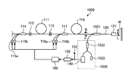
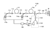
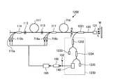





Classifications
-
- H—ELECTRICITY
- H01—ELECTRIC ELEMENTS
- H01S—DEVICES USING THE PROCESS OF LIGHT AMPLIFICATION BY STIMULATED EMISSION OF RADIATION [LASER] TO AMPLIFY OR GENERATE LIGHT; DEVICES USING STIMULATED EMISSION OF ELECTROMAGNETIC RADIATION IN WAVE RANGES OTHER THAN OPTICAL
- H01S3/00—Lasers, i.e. devices using stimulated emission of electromagnetic radiation in the infrared, visible or ultraviolet wave range
- H01S3/10—Controlling the intensity, frequency, phase, polarisation or direction of the emitted radiation, e.g. switching, gating, modulating or demodulating
- H01S3/13—Stabilisation of laser output parameters, e.g. frequency or amplitude
- H01S3/1305—Feedback control systems
-
- G—PHYSICS
- G02—OPTICS
- G02B—OPTICAL ELEMENTS, SYSTEMS OR APPARATUS
- G02B6/00—Light guides; Structural details of arrangements comprising light guides and other optical elements, e.g. couplings
- G02B6/02—Optical fibres with cladding with or without a coating
-
- G—PHYSICS
- G02—OPTICS
- G02B—OPTICAL ELEMENTS, SYSTEMS OR APPARATUS
- G02B6/00—Light guides; Structural details of arrangements comprising light guides and other optical elements, e.g. couplings
- G02B6/24—Coupling light guides
- G02B6/255—Splicing of light guides, e.g. by fusion or bonding
- G02B6/2551—Splicing of light guides, e.g. by fusion or bonding using thermal methods, e.g. fusion welding by arc discharge, laser beam, plasma torch
-
- G—PHYSICS
- G02—OPTICS
- G02B—OPTICAL ELEMENTS, SYSTEMS OR APPARATUS
- G02B6/00—Light guides; Structural details of arrangements comprising light guides and other optical elements, e.g. couplings
- G02B6/24—Coupling light guides
- G02B6/26—Optical coupling means
-
- G—PHYSICS
- G02—OPTICS
- G02B—OPTICAL ELEMENTS, SYSTEMS OR APPARATUS
- G02B6/00—Light guides; Structural details of arrangements comprising light guides and other optical elements, e.g. couplings
- G02B6/24—Coupling light guides
- G02B6/26—Optical coupling means
- G02B6/264—Optical coupling means with optical elements between opposed fibre ends which perform a function other than beam splitting
- G02B6/266—Optical coupling means with optical elements between opposed fibre ends which perform a function other than beam splitting the optical element being an attenuator
-
- H—ELECTRICITY
- H01—ELECTRIC ELEMENTS
- H01S—DEVICES USING THE PROCESS OF LIGHT AMPLIFICATION BY STIMULATED EMISSION OF RADIATION [LASER] TO AMPLIFY OR GENERATE LIGHT; DEVICES USING STIMULATED EMISSION OF ELECTROMAGNETIC RADIATION IN WAVE RANGES OTHER THAN OPTICAL
- H01S3/00—Lasers, i.e. devices using stimulated emission of electromagnetic radiation in the infrared, visible or ultraviolet wave range
- H01S3/0014—Monitoring arrangements not otherwise provided for
-
- H—ELECTRICITY
- H01—ELECTRIC ELEMENTS
- H01S—DEVICES USING THE PROCESS OF LIGHT AMPLIFICATION BY STIMULATED EMISSION OF RADIATION [LASER] TO AMPLIFY OR GENERATE LIGHT; DEVICES USING STIMULATED EMISSION OF ELECTROMAGNETIC RADIATION IN WAVE RANGES OTHER THAN OPTICAL
- H01S3/00—Lasers, i.e. devices using stimulated emission of electromagnetic radiation in the infrared, visible or ultraviolet wave range
- H01S3/05—Construction or shape of optical resonators; Accommodation of active medium therein; Shape of active medium
- H01S3/06—Construction or shape of active medium
- H01S3/063—Waveguide lasers, i.e. whereby the dimensions of the waveguide are of the order of the light wavelength
- H01S3/067—Fibre lasers
- H01S3/06754—Fibre amplifiers
-
- H—ELECTRICITY
- H01—ELECTRIC ELEMENTS
- H01S—DEVICES USING THE PROCESS OF LIGHT AMPLIFICATION BY STIMULATED EMISSION OF RADIATION [LASER] TO AMPLIFY OR GENERATE LIGHT; DEVICES USING STIMULATED EMISSION OF ELECTROMAGNETIC RADIATION IN WAVE RANGES OTHER THAN OPTICAL
- H01S3/00—Lasers, i.e. devices using stimulated emission of electromagnetic radiation in the infrared, visible or ultraviolet wave range
- H01S3/10—Controlling the intensity, frequency, phase, polarisation or direction of the emitted radiation, e.g. switching, gating, modulating or demodulating
- H01S3/102—Controlling the intensity, frequency, phase, polarisation or direction of the emitted radiation, e.g. switching, gating, modulating or demodulating by controlling the active medium, e.g. by controlling the processes or apparatus for excitation
- H01S3/1022—Controlling the intensity, frequency, phase, polarisation or direction of the emitted radiation, e.g. switching, gating, modulating or demodulating by controlling the active medium, e.g. by controlling the processes or apparatus for excitation by controlling the optical pumping
-
- H—ELECTRICITY
- H01—ELECTRIC ELEMENTS
- H01S—DEVICES USING THE PROCESS OF LIGHT AMPLIFICATION BY STIMULATED EMISSION OF RADIATION [LASER] TO AMPLIFY OR GENERATE LIGHT; DEVICES USING STIMULATED EMISSION OF ELECTROMAGNETIC RADIATION IN WAVE RANGES OTHER THAN OPTICAL
- H01S3/00—Lasers, i.e. devices using stimulated emission of electromagnetic radiation in the infrared, visible or ultraviolet wave range
- H01S3/10—Controlling the intensity, frequency, phase, polarisation or direction of the emitted radiation, e.g. switching, gating, modulating or demodulating
- H01S3/13—Stabilisation of laser output parameters, e.g. frequency or amplitude
- H01S3/1306—Stabilisation of the amplitude
-
- G—PHYSICS
- G02—OPTICS
- G02B—OPTICAL ELEMENTS, SYSTEMS OR APPARATUS
- G02B6/00—Light guides; Structural details of arrangements comprising light guides and other optical elements, e.g. couplings
- G02B6/24—Coupling light guides
- G02B6/26—Optical coupling means
- G02B6/264—Optical coupling means with optical elements between opposed fibre ends which perform a function other than beam splitting
-
- H—ELECTRICITY
- H01—ELECTRIC ELEMENTS
- H01S—DEVICES USING THE PROCESS OF LIGHT AMPLIFICATION BY STIMULATED EMISSION OF RADIATION [LASER] TO AMPLIFY OR GENERATE LIGHT; DEVICES USING STIMULATED EMISSION OF ELECTROMAGNETIC RADIATION IN WAVE RANGES OTHER THAN OPTICAL
- H01S3/00—Lasers, i.e. devices using stimulated emission of electromagnetic radiation in the infrared, visible or ultraviolet wave range
- H01S3/005—Optical devices external to the laser cavity, specially adapted for lasers, e.g. for homogenisation of the beam or for manipulating laser pulses, e.g. pulse shaping
-
- H—ELECTRICITY
- H01—ELECTRIC ELEMENTS
- H01S—DEVICES USING THE PROCESS OF LIGHT AMPLIFICATION BY STIMULATED EMISSION OF RADIATION [LASER] TO AMPLIFY OR GENERATE LIGHT; DEVICES USING STIMULATED EMISSION OF ELECTROMAGNETIC RADIATION IN WAVE RANGES OTHER THAN OPTICAL
- H01S3/00—Lasers, i.e. devices using stimulated emission of electromagnetic radiation in the infrared, visible or ultraviolet wave range
- H01S3/05—Construction or shape of optical resonators; Accommodation of active medium therein; Shape of active medium
- H01S3/06—Construction or shape of active medium
- H01S3/063—Waveguide lasers, i.e. whereby the dimensions of the waveguide are of the order of the light wavelength
- H01S3/067—Fibre lasers
- H01S3/0675—Resonators including a grating structure, e.g. distributed Bragg reflectors [DBR] or distributed feedback [DFB] fibre lasers
-
- H—ELECTRICITY
- H01—ELECTRIC ELEMENTS
- H01S—DEVICES USING THE PROCESS OF LIGHT AMPLIFICATION BY STIMULATED EMISSION OF RADIATION [LASER] TO AMPLIFY OR GENERATE LIGHT; DEVICES USING STIMULATED EMISSION OF ELECTROMAGNETIC RADIATION IN WAVE RANGES OTHER THAN OPTICAL
- H01S3/00—Lasers, i.e. devices using stimulated emission of electromagnetic radiation in the infrared, visible or ultraviolet wave range
- H01S3/09—Processes or apparatus for excitation, e.g. pumping
- H01S3/091—Processes or apparatus for excitation, e.g. pumping using optical pumping
- H01S3/094—Processes or apparatus for excitation, e.g. pumping using optical pumping by coherent light
- H01S3/094003—Processes or apparatus for excitation, e.g. pumping using optical pumping by coherent light the pumped medium being a fibre
- H01S3/094011—Processes or apparatus for excitation, e.g. pumping using optical pumping by coherent light the pumped medium being a fibre with bidirectional pumping, i.e. with injection of the pump light from both two ends of the fibre
-
- H—ELECTRICITY
- H01—ELECTRIC ELEMENTS
- H01S—DEVICES USING THE PROCESS OF LIGHT AMPLIFICATION BY STIMULATED EMISSION OF RADIATION [LASER] TO AMPLIFY OR GENERATE LIGHT; DEVICES USING STIMULATED EMISSION OF ELECTROMAGNETIC RADIATION IN WAVE RANGES OTHER THAN OPTICAL
- H01S3/00—Lasers, i.e. devices using stimulated emission of electromagnetic radiation in the infrared, visible or ultraviolet wave range
- H01S3/09—Processes or apparatus for excitation, e.g. pumping
- H01S3/091—Processes or apparatus for excitation, e.g. pumping using optical pumping
- H01S3/094—Processes or apparatus for excitation, e.g. pumping using optical pumping by coherent light
- H01S3/0941—Processes or apparatus for excitation, e.g. pumping using optical pumping by coherent light of a laser diode
- H01S3/09415—Processes or apparatus for excitation, e.g. pumping using optical pumping by coherent light of a laser diode the pumping beam being parallel to the lasing mode of the pumped medium, e.g. end-pumping
-
- H—ELECTRICITY
- H01—ELECTRIC ELEMENTS
- H01S—DEVICES USING THE PROCESS OF LIGHT AMPLIFICATION BY STIMULATED EMISSION OF RADIATION [LASER] TO AMPLIFY OR GENERATE LIGHT; DEVICES USING STIMULATED EMISSION OF ELECTROMAGNETIC RADIATION IN WAVE RANGES OTHER THAN OPTICAL
- H01S3/00—Lasers, i.e. devices using stimulated emission of electromagnetic radiation in the infrared, visible or ultraviolet wave range
- H01S3/14—Lasers, i.e. devices using stimulated emission of electromagnetic radiation in the infrared, visible or ultraviolet wave range characterised by the material used as the active medium
- H01S3/16—Solid materials
- H01S3/1601—Solid materials characterised by an active (lasing) ion
- H01S3/1603—Solid materials characterised by an active (lasing) ion rare earth
- H01S3/1618—Solid materials characterised by an active (lasing) ion rare earth ytterbium
Definitions
- the present invention relates to an optical fiber laser device.
- a so-called return light problem may occur in which the laser light is reflected and re-coupled to the core of the optical fiber in the optical fiber laser device (for example, Patent Document 1 or 2).
- the return light is generated when the laser light irradiated on the processing target is reflected by the processing target. Further, it may be caused by reflection in various places such as cracks in the optical fiber used in the optical fiber laser apparatus and defects in optical connection parts in various places in the apparatus.
- the return light propagates through the optical fiber in the optical fiber laser device in the direction opposite to the laser light output from the laser oscillator, and may damage the components of the optical fiber laser device.
- Examples of the component of the optical fiber laser device that is damaged by the influence of the return light include a light emitting element for guide light that indicates a position where the processing laser light is irradiated. Further, even if no component is provided at the end where the return light reaches, there is a problem in terms of ensuring safety if strong return light is emitted from the end.
- the above-mentioned return light may exceed expectations both qualitatively and quantitatively.
- the return light may be amplified by passing through an oscillator or amplifier in the optical fiber laser device. Further, in the process of propagating through the optical fiber in the optical fiber laser device, stimulated Raman scattering light having a wavelength longer than that of the laser light oscillated by the laser oscillator may be generated. Therefore, when a return light countermeasure assuming a specific intensity of return light with a specific wavelength is employed, the return light cannot be attenuated appropriately, and the components of the optical fiber laser device may be damaged.
- the present invention has been made in view of the above, and an object thereof is to provide an optical fiber laser device having high durability and high output.
- an optical fiber laser device that generates laser light using an amplification optical fiber as an amplification medium in a laser oscillator.
- An output optical fiber that emits the laser light to the outside, a return light attenuating unit that attenuates return light that propagates through the output optical fiber in a direction opposite to the laser light, and a return light attenuating unit.
- a heat converting means for converting the return light into heat
- a temperature monitoring means for measuring a temperature rise of the return light attenuating part due to heat generated by the heat conversion means
- a control unit that reduces or stops the output of the laser beam when a predetermined threshold value or more is reached.
- the temperature monitoring unit includes a first temperature measurement point for measuring heat generated by the heat conversion unit via a heat conductor, and the optical fiber laser device. And measuring a temperature difference between the second temperature measurement point that can be regarded as a reference for temperature in the method.
- the optical fiber laser device is characterized in that the thermal conversion means is configured by fusing an optical fiber in the return light attenuating portion off-axis.
- the optical fiber laser device is characterized in that the thermal conversion means is configured by a high-loss optical fiber provided in the return light attenuation section.
- the optical fiber laser device is characterized in that the thermal conversion means is configured by intentionally bending an optical fiber provided in the return light attenuation section.
- the optical fiber laser device is characterized in that the thermal conversion means is made of a resin that seals the end of the optical fiber provided in the return light attenuation section.
- the thermal conversion unit irradiates the thermal conductor irradiated with the return light emitted from the end of the optical fiber provided in the return light attenuation unit. It is characterized by comprising a surface.
- the optical fiber laser device is characterized in that the return light attenuating unit is arranged in a stage preceding the laser oscillator with the propagation direction of the laser light as a forward direction.
- the return light attenuating unit includes an output side signal port, an input side signal port, and a plurality of excitation light ports, and is input from the excitation light port.
- the pumping light is provided at the end of the optical fiber connected to the input side signal port of the pumping light multiplexer configured to output from the output side signal port connected to the laser oscillator.
- the return light attenuating unit includes an output side signal port, an input side signal port, and a plurality of excitation light ports, and is input from the excitation light port.
- the pumping light is provided at the end of the optical fiber connected to the pumping light port of the pumping light multiplexer configured to output the pumping light from the output-side signal port connected to the laser oscillator.
- the return light attenuating unit has a maximum intensity of the return light among the excitation light ports to which the light source that outputs the excitation light is not connected. It is provided in the terminal part of the optical fiber connected to the port which becomes.
- the return light attenuating unit is connected to an optical reflector having a higher reflectance with respect to the laser light among the two optical reflectors constituting the laser oscillator.
- the optical fiber is provided at the end of the optical fiber.
- an optical fiber laser device is provided between the laser oscillator and the output optical fiber, an optical amplifier using an amplification optical fiber as an amplification medium, an output-side signal port, An input-side signal port and a plurality of pumping light ports; pumping light input from the pumping light port is output from the output-side signal port connected to the optical amplifier;
- a second pumping optical multiplexer configured to be introduced into the optical fiber, and the return light attenuating unit is connected to a terminal part of the optical fiber connected to the pumping light port of the second pumping optical multiplexer. It is provided.
- An optical fiber laser device is an optical fiber laser device that generates laser light using an amplification optical fiber as an amplification medium in a laser oscillator, and guides the laser light to the outside in a forward direction.
- Return optical attenuation composed of an output optical fiber and a plurality of attenuating optical fibers whose bending loss with respect to the return light propagating through the output optical fiber in the opposite direction to the laser light is larger than the bending loss with respect to visible light. And a section.
- the optical fiber laser device is characterized in that the return light attenuating unit is connected to an optical fiber on the upstream side of the high reflectivity reflector of the laser oscillator.
- the return light attenuating unit is a signal port of a pumping optical multiplexer for introducing pumping light used for laser oscillation of the laser oscillator into the amplification optical fiber. It is connected to the optical fiber on the opposite side of the reflector through an optical fiber.
- the return light attenuating unit includes the pumping light of the pumping light multiplexer for introducing pumping light used for laser oscillation of the laser oscillator into the amplification optical fiber. It is connected to the optical fiber on the opposite side of the reflector through a port.
- the return light attenuating unit is connected to an optical fiber branched from an optical multiplexer / demultiplexer provided in the middle of the output optical fiber.
- the optical fiber laser device further includes a visible light emitting unit that introduces the visible light into the output optical fiber via the return light attenuation unit.
- the optical fiber laser device is characterized in that a bend edge wavelength of the attenuation optical fiber is shorter than a wavelength of the return light.
- the optical fiber laser device is characterized in that the attenuation optical fiber is configured to propagate the visible light substantially in a single mode.
- the optical fiber laser device is characterized in that the attenuation optical fiber is configured to propagate red light substantially in a single mode.
- optical fiber laser device is characterized in that a terminal end of the return light attenuation unit is sealed with a resin.
- the optical fiber laser device is characterized in that a photodetector that performs photoelectric conversion is connected to the end of the return light attenuation unit.
- An optical fiber laser device is an optical fiber laser device that generates laser light using an amplification optical fiber as an amplification medium in a laser oscillator, and guides the laser light to the outside in a forward direction.
- the optical fiber for output and the core of the optical fiber for output are propagated in the opposite directions.
- the light intensity of the return light composed of infrared light is attenuated and attenuated from the end opposite to the optical fiber for output.
- the optical fiber laser device is an optical fiber having a core connected to the core of the optical fiber that constitutes the oscillator of the optical fiber laser device, wherein the return light propagation loss unit, In the core, most of the return light is attenuated.
- the optical fiber core constituting the return light propagation loss unit has a visible wavelength loss of the infrared laser light output from the output optical fiber. It is characterized by greater than the loss in the region.
- the optical fiber laser device is characterized in that the core of the optical fiber constituting the return light propagation loss unit has a single mode propagation characteristic in the visible wavelength region.
- the optical fiber laser device further includes a visible light emitting unit that introduces the visible light into the output optical fiber via the return light attenuation unit.
- the optical fiber laser device is characterized in that a photodetector that performs photoelectric conversion is connected to the end of the return light attenuation unit.
- the present invention has been made in view of the above, and an object thereof is to provide an optical fiber laser device having high durability and high output.
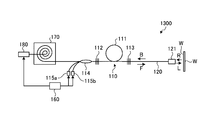
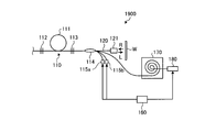
- FIG. 1 is a diagram showing a schematic configuration of an optical fiber laser apparatus according to the first embodiment of the present invention.
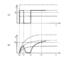
- FIG. 2 is a graph illustrating an example of determination using a threshold value related to temperature performed by the control unit.
- FIG. 3 is a graph illustrating an example of determination using a threshold value related to temperature performed by the control unit.
- FIG. 4 is a diagram schematically showing the configuration of the return light attenuation module according to the first configuration example.
- FIG. 5 is a diagram illustrating the off-axis fusion of the optical fiber used in the first configuration example.
- FIG. 6 is a diagram schematically showing the configuration of the return light attenuation module according to the second configuration example.
- FIG. 7 is a diagram showing a high-loss optical fiber used in the second configuration example.
- FIG. 1 is a diagram showing a schematic configuration of an optical fiber laser apparatus according to the first embodiment of the present invention.
- FIG. 2 is a graph illustrating an example of determination using a threshold value related to temperature performed
- FIG. 8 is a diagram schematically showing the configuration of the return light attenuation module according to the third configuration example.
- FIG. 9 is a diagram schematically showing the configuration of the return light attenuation module according to the fourth configuration example.
- FIG. 10 is a cross-sectional view schematically showing the configuration of the end of the optical fiber used in the fourth configuration example.
- FIG. 11 is a diagram schematically showing a configuration of a return light attenuation module according to a fifth configuration example.
- FIG. 12 is a diagram illustrating a schematic configuration of a termination portion according to Configuration Example 1.
- FIG. 13 is a diagram illustrating a schematic configuration of a termination portion according to Configuration Example 2.
- FIG. 14 is a diagram illustrating a schematic configuration of a termination portion according to Configuration Example 3.
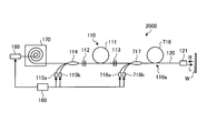
- FIG. 15 is a diagram showing a schematic configuration of an optical fiber laser apparatus according to the second embodiment of the present invention.
- FIG. 16 is a diagram showing a schematic configuration of an optical fiber laser apparatus according to the third embodiment of the present invention.
- FIG. 17 is a diagram showing a schematic configuration of an optical fiber laser apparatus according to the fourth embodiment of the present invention.
- FIG. 18 is a diagram showing a schematic configuration of an optical fiber laser device according to the fifth embodiment of the present invention.
- FIG. 19 is a diagram showing a schematic configuration of an optical fiber laser apparatus according to the sixth embodiment of the present invention.
- FIG. 20 is a diagram showing a schematic configuration of an optical fiber laser device according to the seventh embodiment of the present invention.
- FIG. 20 is a diagram showing a schematic configuration of an optical fiber laser device according to the seventh embodiment of the present invention.
- FIG. 21 is a diagram showing a schematic configuration of an optical fiber laser apparatus according to the eighth embodiment of the present invention.
- FIG. 22 is a diagram showing a schematic configuration of an optical fiber laser device according to the ninth embodiment of the present invention.
- FIG. 23 is a diagram showing a schematic configuration of an optical fiber laser device according to the tenth embodiment of the present invention.
- FIG. 24 is a diagram showing a schematic configuration of the optical fiber laser apparatus according to the eleventh embodiment of the present invention.
- FIG. 25 is a diagram showing a schematic configuration of an optical fiber laser apparatus according to the twelfth embodiment of the present invention.
- FIG. 26 is a diagram showing a schematic configuration of the optical fiber laser apparatus according to the thirteenth embodiment.
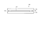
- FIG. 27 is a diagram showing the configuration of the return light attenuation module and its periphery.
- FIG. 28 is a side view of the return light attenuation module.
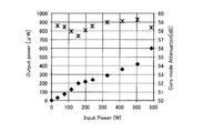
- FIG. 29 is a graph showing the temperature of the optical fiber with respect to the input intensity to the return light attenuation module.
- FIG. 30 is a graph showing the output intensity with respect to the input intensity to the return light attenuation module.
- FIG. 31 is a diagram showing a schematic configuration of the optical fiber laser device according to the fourteenth embodiment.
- FIG. 32 is a diagram illustrating an example of resin sealing at the end of the optical fiber in the termination processing unit.
- FIG. 33 is a diagram showing a schematic configuration of the optical fiber laser apparatus according to the fifteenth embodiment.
- FIG. 34 is a diagram showing a schematic configuration of the optical fiber laser apparatus according to the sixteenth embodiment.
- FIG. 35 is a diagram showing a schematic configuration of the optical fiber laser apparatus according to the seventeenth embodiment.
- FIG. 36 is a diagram showing a schematic configuration of the optical fiber laser apparatus according to the eighteenth embodiment.
- FIG. 37 is a diagram showing a schematic configuration of the optical fiber laser apparatus according to the nineteenth embodiment.
- FIG. 38 is a diagram showing a schematic configuration of the optical fiber laser apparatus according to the twentieth embodiment.
- FIG. 39 is a diagram showing a schematic configuration of the optical fiber laser apparatus according to the twenty-first embodiment.
- FIG. 40 is a diagram showing a schematic configuration of the optical fiber laser apparatus according to the twenty-second embodiment.
- FIG. 41 is a diagram showing a schematic configuration of the optical fiber laser apparatus according to the twenty-third embodiment.
- the cutoff wavelength is ITU-T (International Telecommunication Union) This is the cut-off wavelength according to the 22m method defined by 650.1.
- ITU-T G International Telecommunication Union
- the definition and measurement method in 650.1 shall be followed as appropriate.
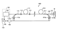
- FIG. 1 is a diagram showing a schematic configuration of an optical fiber laser apparatus 100 according to the first embodiment.
- the optical fiber laser device 100 according to the first embodiment is an optical fiber laser type device that generates laser light using an amplification optical fiber 111 as an amplification medium in a laser oscillator 110.
- the optical fiber laser device 100 propagates the output optical fiber 120 that emits the output laser light L in the forward direction (arrow F in the figure) and at least the output optical fiber 120 in the reverse direction (arrow B in the figure).
- a temperature monitoring unit 150 that measures the temperature rise of the optical attenuation module 140; and a control unit 160 that reduces or stops the output of the output laser light L when the temperature measured by the temperature monitoring unit 150 reaches a predetermined threshold value or more. It has.
- a forward direction F and a reverse direction B are defined as shown in FIG.
- the laser oscillator 110 includes an amplification optical fiber 111, a first optical reflector 112 provided on the reverse side of the amplification optical fiber 111, and a forward side of the amplification optical fiber 111. And a second light reflector 113 provided in the.
- Each of the optical fibers from the output optical fiber 120 including at least the laser oscillator 110, and preferably the front and back thereof, to the signal port optical fiber of the pumping optical multiplexer 114 substantially emits light having a wavelength of 1000 nm to 1200 nm.
- Mode field distribution in which the majority of the field or electric field strength distribution in the core of the optical fiber is composed of the fundamental mode and the other several percent is composed of several higher-order modes (a few modes).
- optical fiber having a core having a characteristic of propagating with a light having a light beam.
- the single mode substantially refers to the light propagation mode defined above.
- Each of these optical fibers is preferably configured such that the mode field diameter at the wavelength of the output laser light is substantially the same, and at least the first optical reflector 112 constituting the laser oscillator 110 to the second optical fiber.
- the core extending to the optical fiber constituting the optical reflector 113 is preferably configured such that the mode field diameters at the wavelength of the output laser light are substantially the same, and the mode propagation characteristics are substantially the same.
- ytterbium (Yb) ions as an amplification substance are added to a core portion made of silica glass, and an outer clad layer made of silica glass and an outer clad layer made of resin or the like on the outer periphery of the core portion.
- Yb ytterbium
- the core portion of the amplification optical fiber 111 has a numerical aperture (NA) of 0.08, for example, and is configured to propagate light having a wavelength of 1000 nm to 1200 nm in a single mode.
- the length of the amplification optical fiber 111 is, for example, 25 m.
- the absorption coefficient of the core portion of the amplification optical fiber 111 is, for example, 200 dB / m at a wavelength of 1070 nm. Further, the power conversion efficiency from the pumping light input to the core portion to the laser light that oscillates is, for example, 70%.
- the first light reflector 112 and the second light reflector 113 are composed of, for example, fiber Bragg gratings (FBGs) having different wavelength characteristics.
- the 1st light reflector 112 and the 2nd light reflector 113 are comprised by providing a diffraction grating in the core of an optical fiber.
- the first light reflector 112 and the second light reflector 113 are configured as a double clad type optical fiber having an inner clad so that the light of the pumping light wavelength propagates in the multimode in the inner clad. It is preferable to configure.
- the first light reflector 112 has a characteristic that the center wavelength is, for example, 1070 nm, the reflectance in the wavelength band of about 2 nm width around the center wavelength and the periphery thereof is about 100%, and light with a wavelength of 915 nm is almost transmitted.
- the second light reflector 113 has a center wavelength that is substantially the same as that of the first light reflector 112, for example, 1070 nm, has a reflectance at the center wavelength of about 10% to 30%, and has a reflection wavelength band.
- the full width at half maximum is about 1 nm, and light having a wavelength of 915 nm has a characteristic of almost transmitting.
- the first light reflector 112 and the second light reflector 113 may have characteristics of transmitting almost light having a wavelength of 975 nm. preferable.
- the laser oscillator 110 oscillates a laser beam having a wavelength of 1070 nm when pumping light having a wavelength of 915 nm is introduced, and outputs the laser beam from the second light reflector 113 to the output optical fiber 120. It becomes.
- the laser oscillator 110 oscillates output laser light having a wavelength of 1070 nm when pump light having a wavelength of 915 nm is introduced into the amplification optical fiber 111, and outputs the output laser light from the second optical reflector 113. Output to the optical fiber 120.
- the output laser light L output to the output optical fiber 120 is irradiated to the workpiece W via the irradiation head 121.
- the output laser light L irradiated to the workpiece W generates reflected light on the surface of the workpiece W, and a part of the reflected light is introduced into the output optical fiber 120 via the irradiation head 121.
- the reflected light introduced into the output optical fiber 120 may propagate in the opposite direction through the core of the output optical fiber 120 and may pass through the first light reflector 112.
- Raman scattered light or stimulated Brillouin scattered light generated by the reflected light may also pass through the first light reflector 112 and reach the terminal portion 130. Therefore, although the light transmitted through the first light reflector 112 includes a plurality of components, in this specification, at least the core of the output optical fiber 120 propagates in the direction opposite to the output laser light L.
- the light to be called is called return light R.
- the optical fiber laser device 100 adopts a so-called forward pumping type configuration.
- a pumping light multiplexer 114 for outputting pumping light to the first light reflector 112 is provided in front of the first light reflector 112.
- the optical fiber laser device 100 introduces pumping light from the front stage of the first light reflector 112 toward the amplification optical fiber 111.
- the excitation light multiplexer 114 is configured by, for example, a TFB (Tapered Fiber Bundle).
- the pumping light multiplexer 114 includes a forward direction signal port optical fiber, a backward direction signal port optical fiber, and a plurality of pumping light port optical fibers constituting both ends.
- a core extends between the forward-side signal port optical fiber and the backward-side signal port optical fiber, and the core preferably has single-mode propagation characteristics at the lasing wavelength. There may be.
- the pumping light port is composed of an optical fiber having a core having a multimode propagation characteristic at the pumping light wavelength (multimode).
- the multimode optical fiber constituting each pumping light port is configured so that the multimode core surrounds the core of the optical fiber constituting the forward signal port.
- the forward signal port of the excitation light multiplexer 114 is coupled so that the core extending from the reverse signal port is coupled to the single mode core, and the core extending from each excitation light port is coupled to the inner cladding. It is connected to a double clad optical fiber. Further, the double clad optical fiber is connected to the amplification optical fiber 111 via the first optical reflector 112. Thereby, the light of the laser oscillation wavelength input to the reverse side signal port propagates to the core of the amplification optical fiber 111 substantially in a single mode. On the other hand, the light of the pumping wavelength input to each pumping light port propagates to the inner cladding of the amplification optical fiber 111 in multimode.
- the pumping light port of the pumping light multiplexer 114 is connected to the pumping laser diodes 115a and 115b.
- the reverse-side signal port of the excitation light multiplexer 114 is connected to the termination unit 130.
- the forward-side signal port and the backward-side signal port have the cores extending at both ends, so that the intensity of the return light is large, and the backward-side signal port of the excitation light multiplexer 114 serves as a port for connecting the termination unit 130.
- the termination unit 130 is not limited to that connected to the reverse direction signal port of the excitation light multiplexer 114.
- the pumping light multiplexer 114 includes a plurality of pumping light ports, and pumping laser diodes are not necessarily connected to all pumping light ports. Therefore, there may be a so-called surplus port to which the pumping laser diode is not connected.
- the connection destination of the surplus port can also be the termination unit 130 of this embodiment.
- the surplus ports having the maximum return light intensity and connect the configuration of the termination unit 130.
- another device is connected to the reverse direction signal port of the pumping light multiplexer 114.
- the pumping light port having the maximum return light intensity among the remaining ports is connected to the terminal unit 130. It is suitable as a port to be connected.
- FIG. 1 only one termination unit 130 is illustrated in FIG. 1, there may be a plurality of termination units 130 in the optical fiber laser device 100, in which case at least one of the plurality of termination units 130 is present.
- the present invention may be applied to the terminal portion 130. Of course, it is not excluded to apply the present invention to a plurality of terminal portions 130 simultaneously.
- the termination unit 130 of the optical fiber laser device 100 includes a return light attenuation module 140.
- the termination unit 130 includes only the return light attenuation module 140, but the termination unit 130 may include other components as described in detail later.
- the return light attenuation module 140 is disposed so as to be in contact with the heat conversion means 141 that converts the return light output from the excitation light multiplexer 114 into heat, and the heat conversion means 141.
- the heat conductor 142 which conducts the heat which the means 141 emits, and the 1st temperature measurement point 151 provided on the heat conductor 142 are provided.
- the first temperature measurement point 151 is a position where a temperature sensor such as a thermistor or a thermocouple is disposed.
- the heat conversion means 141 is a means for converting the light energy of the return light into heat energy, which will be described later with a specific example.
- the heat conductor 142 is made of, for example, a metal plate, and the heat conversion means 141 is fixed on the heat conductor 142 with a resin or the like. Therefore, the measurement temperature at the first temperature measurement point 151 provided on the heat conductor 142 appropriately reflects the heat generated by the heat conversion means 141. Further, the heat generated by the heat conversion means 141 reflects the thermal load received by the optical fiber at the end portion 130. As a result, the measurement temperature at the first temperature measurement point 151 provided on the thermal conductor 142 reflects the thermal load that the optical fiber at the termination portion 130 receives.
- the temperature monitoring means 150 converts an electrical signal such as a voltage acquired from a temperature sensor such as a thermistor or a thermocouple provided at the first temperature measurement point 151 into temperature information at the first temperature measurement point 151.
- a temperature sensor such as a thermistor or a thermocouple at the second temperature measurement point 152 that can be regarded as a temperature reference in the optical fiber laser device 100.
- the measured temperature at the first temperature measurement point 151 provided on the thermal conductor 142 reflects the thermal load received by the optical fiber at the terminal end portion 130, other than the heat generation of the optical fiber at the terminal end portion 130. May be affected by thermal disturbances. Therefore, due to thermal disturbance other than the heat generation of the optical fiber at the termination portion 130, a situation may occur in which the measured temperature at the first temperature measurement point 151 cannot correctly reflect the thermal load received by the optical fiber at the termination portion 130. .
- a temperature sensor such as a thermistor or a thermocouple is arranged at the second temperature measurement point 152 that can be regarded as a temperature reference in the optical fiber laser device 100, and the temperature at the first temperature measurement point 151 and the second temperature measurement are measured.
- the temperature monitoring unit 150 is configured to measure the temperature difference from the temperature at the point 152.
- the second temperature measurement point 152 may be a predetermined point of a heat sink for cooling other heat generating components such as the excitation laser diodes 115a and 115b and the amplification optical fiber 111.
- the heat conductor 142 which transfers the heat of the heat conversion means 141 can be brought into contact with the heat sink.
- the control unit 160 Information on the temperature at the first temperature measurement point 151 or the temperature difference between the temperature at the first temperature measurement point 151 and the temperature at the second temperature measurement point 152 acquired by the temperature monitoring unit 150 is sent to the control unit 160.
- the temperature monitoring unit 150 may be configured as one function of the control unit 160.
- the control unit 160 does not need to be a special control device for carrying out the present invention, and a general general-purpose control device can be used.
- control unit 160 includes a CPU (Central Processing Unit), a ROM (Read Only Memory), a RAM (Random Access Memory), an I / F (Interface), and a bus that interconnects them.
- the CPU controls each unit based on programs and data stored in the ROM.
- the ROM is a non-volatile semiconductor storage device and stores programs and data.
- the RAM is a volatile semiconductor storage device and operates as a work area when the CPU executes a program.
- the I / F includes, for example, a DAC (Digital Analog Converter), an ADC (Analog Digital Converter), and the like.
- the I / F converts the digital data supplied from the CPU into an analog signal, supplies it to each control part such as the excitation laser diodes 115a and 115b, and converts the analog current signal from the thermistor or thermocouple into a digital signal. Convert.
- the bus is a signal line group for connecting the CPU, ROM, RAM, and I / F to each other and enabling data exchange between them.
- the control unit 160 is not limited to the one using a CPU or the like. For example, a DSP (Digital Signal Processor) may be used, or an analog control method may be used instead of a digital control method.
- a DSP Digital Signal Processor
- the control unit 160 compares the temperature at the first temperature measurement point 151 acquired by the temperature monitoring unit 150 with a predetermined threshold value, and when the temperature at the first temperature measurement point 151 becomes equal to or higher than the predetermined threshold value. Then, a control signal for reducing or stopping the output is supplied to the excitation laser diodes 115a and 115b.
- the threshold value is preferably set to a value having a predetermined margin with respect to a temperature at which thermal damage of an optical fiber such as a fiber fuse obtained experimentally is considered to occur.
- the control unit 160 compares the temperature difference between the temperature at the first temperature measurement point 151 and the temperature at the second temperature measurement point 152 with a predetermined threshold value in the termination unit 130. This is preferable because the thermal load applied to the optical fiber can be measured with higher accuracy.
- the excitation laser diodes 115a and 115b that have received the control signal for reducing or stopping the output from the control unit 160 reduce or stop the output of the excitation light introduced into the laser oscillator 110. Then, the output laser light L output from the optical fiber laser device 100 is lowered or stopped, and the return light R introduced into the output optical fiber 120 via the irradiation head 121 is also lowered or stopped. As a result, the load received by the optical fiber in the termination portion 130 is suppressed, and high durability and high output performance of the optical fiber laser device 100 are realized.
- FIG. 2 and 3 are graphs showing an example of determination using a threshold value related to temperature performed by the control unit 160.
- FIG. 2 and 3 are graphs showing an example of determination using a threshold value related to the intensity of the return light for comparison.
- the determination using the threshold regarding the intensity of the return light is a determination method using, for example, the intensity of the return light detected by a light receiving element or the like and using the threshold for the received light intensity.
- the upper graph (a) in FIG. 2 and FIG. 3 shows an example of determination using a threshold value related to the intensity of return light
- the lower graph (b) shows an example of determination using a threshold value related to temperature.
- the upper graph (a) and the lower graph (b) share a time axis: t (horizontal axis), and are graphs related to the time variation of the same return light.
- t horizontal axis
- the vertical axis (I) in the upper graph (a) indicates the intensity of the return light
- the vertical axis (T) in the lower graph (b) indicates the measured temperature.
- the intensity of the return light changes abruptly with time, while the measured temperature changes relatively slowly with time.
- the intensity of the return light corresponds to the degree of increase in the measurement temperature and the temperature at the time of saturation. Therefore, even if the intensity of the return light reaches the value I 0 or more, such as from time t 0 to time t 1 , if the time is short, the measured temperature is equal to the threshold T Does not reach 0 . In such a case, the load received by the optical fiber in the terminal section 130 is not so great as to cause damage to the optical fiber from the viewpoint of time history, and therefore the output laser light L output from the optical fiber laser device 100 is reduced. There is no need to suppress it.
- the time during which the intensity of the return light reaches the value I 0 or more is from time t 10 to time t 11 , from time t 12 to time t 13 , and from time t 14 to time t 14. 15 and the situation where the intensity of the return light is high is repeated intermittently.
- the load received by the optical fiber at the termination portion 130 is not large, it is not necessary to suppress the output laser light L output from the optical fiber laser device 100.
- the optical fiber laser device 100 takes into account not only the intensity of the return light but also the time during which the situation where the intensity of the return light is high continues, Judging the amount. As a result, the determination as to whether or not to suppress the output laser L output from the optical fiber laser device 100 is made appropriate, and the unnecessary output laser light L is suppressed, that is, the output of the unnecessary output laser L is reduced or stopped. Less. As a result, high durability and high output performance of the optical fiber laser device 100 are realized.
- the return light attenuation module 140 will be described.
- various configuration examples may be assumed in the configuration of the return light attenuation module 140.
- the configuration examples described below are exemplary listings of the return light attenuation module 140, and each configuration example can be replaced with the return light attenuation module 140 in the optical fiber laser device 100. Accordingly, in the configuration example described below, only the portion corresponding to the return light attenuation module 140 is disclosed, but the other configurations can be regarded as the same as the optical fiber laser device 100.
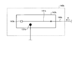
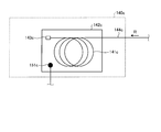
- FIG. 4 is a diagram schematically showing the configuration of the return light attenuation module 140a according to the first configuration example
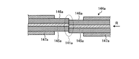
- FIG. 5 is a diagram showing the axial misalignment fusion 141a of the optical fiber used in the first configuration example.
- the return light attenuation module 140a according to the first configuration example includes an optical fiber 144a on which the off-axis fusion 141a is applied and a heat conductor 142a that conducts heat generated by the off-axis fusion 141a portion. And.
- the return light attenuating module 140a uses the off-axis fusion bond 141a of the optical fiber 144a as heat conversion means for converting the return light R that has propagated to the optical fiber 144a at the end portion into heat. It is.
- the off-axis fusion 141a of the optical fiber 144a is disposed on the heat conductor 142a, and the optical fiber 144a is fixed on the heat conductor 142a by a fixing material such as a silicone resin.
- a groove is formed on the surface of the heat conductor 142a, and the optical fiber 144a is accommodated in the groove.
- the first temperature measurement point 151a is set to an appropriate position for measuring the heat generated by the off-axis fusion 141a of the optical fiber 144a through the thermal conductor 142a. That is, for example, the first temperature measurement point 151a is preferably disposed near the off-axis fused portion 141a.
- the first temperature measurement point 151a is configured such that a temperature sensor such as a thermistor or a thermocouple is arranged to measure the temperature at the first temperature measurement point 151a.
- the sealing portion 143a provided at the end of the optical fiber 144a is a component for sealing the end of the optical fiber 144a.
- FIG. 5 is a cross-sectional view of the optical fiber 144a in which the periphery of the off-axis fusion bond 141a indicated by “x” in FIG. 4 is enlarged.
- the central axes of the cores 145a are fused while being displaced in the radial direction at the misaligned fusion 141a portion. Therefore, the return light R propagating through the optical fiber 144a receives a large loss at the off-axis fused portion 141a. That is, the return light R loses energy at the off-axis fused portion 141a, and the lost energy is converted into leakage light or heat.
- the amount of loss in the misalignment fusion 141a can be adjusted by the number of locations where the misalignment fusion 141a is applied and the misalignment amount.
- the coating 147a is provided around the clad 146a in a portion away from the off-axis fusion 141a, but the coating 147a is not necessarily required. In consideration of the influence of heat generation, the coating 147a may be peeled off around or entirely around the off-axis fusion bond 141a of the optical fiber 144a.
- the return light attenuation module 140 a configured as described above is a configuration example that can be replaced with the return light attenuation module 140 in the optical fiber laser device 100.
- FIG. 6 is a diagram schematically showing the configuration of the return light attenuation module 140b according to the second configuration example
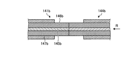
- FIG. 7 is a diagram showing the high-loss optical fiber 141b used in the second configuration example.
- the return light attenuation module 140b according to the second configuration example includes an optical fiber 144b provided with a high-loss optical fiber 141b, and a heat conductor 142b that conducts heat generated by the high-loss optical fiber 141b. It is equipped with.
- the return light attenuation module 140b uses a high-loss optical fiber 141b as heat conversion means for converting the return light R that has propagated to the optical fiber 144b at the end portion into heat.
- the high-loss optical fiber 141b fused to the optical fiber 144b is arranged on the heat conductor 142b, and the optical fiber 144b and the high-loss optical fiber 141b are made of the heat conductor 142b by, for example, a silicone resin. Secure on top.
- the first temperature measurement point 151b is set at an appropriate position for measuring the heat generated by the high-loss optical fiber 141b through the thermal conductor 142b. That is, for example, the first temperature measurement point 151b is preferably disposed near the high-loss optical fiber 141b portion.
- the first temperature measurement point 151b is configured such that a temperature sensor such as a thermistor or a thermocouple is disposed and the temperature at the first temperature measurement point 151b can be measured.
- sealing portion 143b provided at the end of the high-loss optical fiber 141b is a component for sealing the end of the high-loss optical fiber 141b.
- FIG. 7 is an enlarged cross-sectional view of the fused portion between the optical fiber 144b and the high-loss optical fiber 141b indicated by “x” in FIG.
- the core 145b of the high-loss optical fiber 141b is made of a material different from the core of the optical fiber 144b.
- a metal impurity such as cobalt is added to the core 145b of the high-loss optical fiber 141b.
- the clad 146b of the high-loss optical fiber 141b may be the same as the clad of the optical fiber 144b.
- the return light R propagating through the high-loss optical fiber 141b receives a large loss. That is, the return light R loses energy in the high-loss optical fiber 141b, and the lost energy is mainly converted into heat.
- the amount of loss in the high-loss optical fiber 141b can be adjusted by the length of the high-loss optical fiber 141b and the concentration of metal impurities.
- the coating 147b is provided around the cladding 146b, but the coating 147b is not necessarily required. In consideration of the influence of heat generation, the coating 147b may be stripped from a part or all of the high-loss optical fiber 141b.
- the return light attenuation module 140b configured as described above is a configuration example that can be replaced with the return light attenuation module 140 in the optical fiber laser device 100. Note that the return light attenuation module 140b described above may be configured to apply the off-axis fusion 141a of the first configuration example to the high-loss optical fiber 141b.
- FIG. 8 is a diagram schematically showing the configuration of the return light attenuation module 140c according to the third configuration example.
- the return light attenuation module 140c according to the third configuration example includes an optical fiber 144c intentionally provided with a bent portion 141c and a heat conductor that conducts heat generated by the bent portion 141c of the optical fiber 144c. 142c.
- the return light attenuation module 140c uses the bending loss of the optical fiber 144c as heat conversion means for converting the return light R that has propagated to the optical fiber 144c at the end portion into heat.
- the bending loss is a phenomenon in which the loss received by the return light R propagating through the bent optical fiber 144c is higher than the loss received by the return light R propagating through the linear optical fiber 144c. Therefore, the return light R propagating through the optical fiber 144c intentionally provided with the bent portion 141c receives a large loss.
- the amount of loss can be adjusted by the radius of curvature and length of the bent portion 141c.
- the bent portion 141c is arranged on the heat conductor 142c, and the optical fiber 144c provided with the bent portion 141c is fixed on the heat conductor 142c by, for example, a silicone-based resin or the like.
- the first temperature measurement point 151c is set at an appropriate position for measuring the heat generated by the bent portion 141c of the optical fiber 144c through the thermal conductor 142c. That is, for example, the first temperature measurement point 151c is preferably disposed near the bent portion 141c of the optical fiber 144c.
- the first temperature measurement point 151c is configured such that a temperature sensor such as a thermistor or a thermocouple is arranged to measure the temperature at the first temperature measurement point 151c.
- sealing part 143c provided in the edge part of the optical fiber 144c is a component for sealing the terminal end of the optical fiber 144c.
- the return light attenuation module 140 c configured as described above is a configuration example that can be replaced with the return light attenuation module 140 in the optical fiber laser device 100.
- the return light attenuation module 140c described above has a configuration in which the bending portion 141c is applied to the high-loss optical fiber 141b in the second configuration example, and the misalignment fusion 141a in the first configuration example is applied to the bending portion 141c. It is also possible.
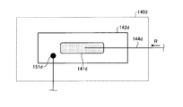
- FIG. 9 is a diagram schematically showing the configuration of the return light attenuation module 140d according to the fourth configuration example
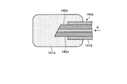
- FIG. 10 is a sectional view schematically showing the configuration of the end of the optical fiber 144d used in the fourth configuration example. It is.
- the return light attenuation module 140d according to the fourth configuration example includes a sealing member 141d that seals the end of the optical fiber 144d, and a heat conductor 142d that conducts heat generated by the sealing member 141d. It is equipped with.
- the return light attenuation module 140d is a sealing member 141d that seals the end of the optical fiber 144d as heat conversion means that converts the return light R that has propagated to the end optical fiber 144d into heat.
- the sealing member 141d is, for example, a resin or the like, and has a property of scattering or absorbing the return light R emitted from the endmost part of the optical fiber 144d.
- the return light R scattered or absorbed by the sealing member 141d directly generates heat or indirectly reaches the heat conductor 142d and indirectly generates heat at the sealing member 141d.
- a sealing member 141d that seals the end of the optical fiber 144d is disposed on the heat conductor 142d, and the optical fiber 144d is fixed on the heat conductor 142d with, for example, a silicone resin.
- the first temperature measurement point 151d is set at an appropriate position for measuring the heat generated by the sealing member 141d through the thermal conductor 142d. That is, for example, the first temperature measurement point 151d is preferably disposed near the sealing member 141d.
- the first temperature measurement point 151d is configured with a temperature sensor such as a thermistor or a thermocouple so that the temperature at the first temperature measurement point 151d can be measured.
- FIG. 10 shows the enlarged end of the optical fiber 144d sealed by the sealing member 141d.
- the core 145d and the clad 146d at the end of the optical fiber 144d are cut obliquely with respect to the optical axis of the optical fiber 144d. This is preferable because the amount of the return light R reflected at the end of the optical fiber 144d and returning to the core is reduced.
- the core 145d and the clad 146d at the end of the optical fiber 144d may be cut perpendicular to the optical axis of the optical fiber 144d.
- a coating 147d is provided around the cladding 146d, but the coating 147d is not necessarily required. In consideration of the influence of heat generation, the coating 147d may be peeled off at the end or all of the optical fiber 144d.
- the return light attenuation module 140 d configured as described above is a configuration example that can be replaced with the return light attenuation module 140 in the optical fiber laser device 100.
- the configuration in which the end of the optical fiber 144d in the return light attenuation module 140d is sealed with the sealing member 141d may be applied to the sealing portions 143a, 143b, and 143c in the first to third configuration examples described above. Is possible.
- FIG. 11 is a diagram schematically showing the configuration of the return light attenuation module 140e according to the fifth configuration example.
- the return light attenuation module 140e according to the fifth configuration example includes an optical fiber 144e and an irradiation surface 141e on the heat conductor 142e irradiated with the return light R emitted from the end of the optical fiber 144e. And.
- the return light attenuation module 140e uses the irradiation surface 141e on the heat conductor 142e as heat conversion means for converting the return light R that has propagated to the optical fiber 144e at the end portion into heat. It is.
- the irradiation surface 141e on the heat conductor 142e is a metal surface that has been subjected to surface processing so as to absorb the irradiated light and generate heat, and converts the return light R that has propagated to the optical fiber 144e into heat. It has a function. That is, the heat generated by the irradiation surface 141e reflects the intensity of the return light R including the time history effect.
- the first temperature measurement point 151e is set at an appropriate position for measuring the heat generated by the irradiation surface 141e through the heat conductor 142e. That is, for example, the first temperature measurement point 151e is preferably arranged near the irradiation surface 141e.
- the first temperature measurement point 151e is configured such that a temperature sensor such as a thermistor or a thermocouple is disposed, and the temperature at the first temperature measurement point 151e can be measured.
- the core 145e and the clad 146e at the end of the optical fiber 144e are cut obliquely with respect to the optical axis of the optical fiber 144e. This is preferable because the amount of the return light R reflected at the end of the optical fiber 144e is reduced.
- the core 145e and the clad 146e at the end of the optical fiber 144e may be cut perpendicular to the optical axis of the optical fiber 144e.
- the coating 147e is provided around the cladding 146e, but the coating 147e is not necessarily required. In consideration of the influence of heat generation, the coating 147e may be peeled off at the end or all of the optical fiber 144e.
- the return light attenuation module 140e configured as described above is a configuration example that can be replaced with the return light attenuation module 140 in the optical fiber laser device 100.
- the terminal unit 130 of the optical fiber laser device 100 shown in FIG. 1 includes only the return light attenuation module 140, but may include other components.
- a configuration example of the termination unit 130 including a configuration other than the return light attenuation module 140 will be described.
- the configuration examples described below are examples of the termination unit 130, and each configuration example can be replaced with the termination unit 130 in the optical fiber laser device 100. Therefore, in the configuration example described below, only the portion corresponding to the termination unit 130 is disclosed, but the other configurations can be regarded as the same as the optical fiber laser device 100.
- the configuration example of the termination unit described below includes the return light attenuation module 140.
- the return light attenuation module 140 can be replaced with the return light attenuation modules 140a, 140b, 140c, 140d, and 140e according to the first to fifth configuration examples.
- the description of the configuration of the return light attenuation module 140 is omitted, but it is assumed that the configuration is the same as that of the return light attenuation modules 140a, 140b, 140c, 140d, and 140e according to the first to fifth configuration examples described above. obtain.
- FIG. 12 is a diagram illustrating a schematic configuration of the termination portion 131 according to Configuration Example 1. As illustrated in FIG. As shown in FIG. 12, the termination unit 131 according to Configuration Example 1 is configured to include a wavelength division multiplexing optical multiplexer / demultiplexer 132, a visible light emitting unit 133, and a return light attenuation module 140.
- the visible light emitting unit 133 is a laser diode that emits red laser light, for example. As described above, the laser beam output from the optical fiber laser device 100 has a wavelength of, for example, 1070 nm and is not a laser beam in the visible light region. Therefore, it is difficult to confirm the position where the output laser beam is irradiated.
- the visible light emitting unit 133 is a light source for outputting guide light G for confirming the position where the output laser light is irradiated.
- the wavelength division multiplexing optical multiplexer / demultiplexer 132 includes an optical fiber through which the return light R propagates, an optical fiber to which the visible light emitting unit 133 is connected, and an optical fiber to which the return light attenuation module 140 is connected. It is a device for wavelength-selective optical multiplexing / demultiplexing.
- the wavelength division multiplexing optical multiplexer / demultiplexer 132 has a wavelength characteristic that allows the guide light G output from the visible light emitting unit 133 to pass through the optical fiber through which the return light R propagates with low loss.
- the wavelength division multiplexing optical multiplexer / demultiplexer 132 has a wavelength characteristic that allows the return light R to pass through the optical fiber to which the return light attenuation module 140 is connected with low loss.
- the wavelength division multiplexing optical multiplexer / demultiplexer 132 has a wavelength characteristic that greatly attenuates the return light R when it passes through the optical fiber to which the visible light emitting unit 133 is connected.
- the termination unit 131 irradiates at least the return light attenuation module 140 that attenuates the return light R that propagates through the output optical fiber 120 in the direction opposite to the output laser light, and the output laser light. And a visible light emitting unit 133 for outputting a guide light G for confirming the position of the light.
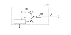
- FIG. 13 is a diagram illustrating a schematic configuration of the termination unit 134 according to Configuration Example 2. As illustrated in FIG. As shown in FIG. 13, the termination unit 134 according to Configuration Example 2 is configured to include an optical multiplexer / demultiplexer 135, a photodetector 136, and a return light attenuation module 140.
- the optical multiplexer / demultiplexer 135 is a device called a so-called Tap coupler, in which an optical fiber through which the return light R propagates, an optical fiber to which the photodetector 136 is connected, and a return light attenuation module 140 are connected. It is a device for optical multiplexing / demultiplexing while adjusting the light intensity ratio with the optical fiber.
- the optical multiplexer / demultiplexer 135 branches the input return light R into a return light R 1 output to the return light attenuation module 140 and a return light R 2 output to the photodetector 136. At this time, the branching ratio of the light intensity between the return light R 1 and the return light R 2 is, for example, 1: 100 to 1: 100000.
- the optical multiplexer / demultiplexer 135 is also called a 20 dB to 50 dB coupler based on the light intensity branching ratio.
- the photodetector 136 is configured by a photodiode, for example.
- the photodetector 136 composed of a photodiode monitors the light intensity of the return light R 2 input to the photodetector 136 by converting the light intensity of the input light into an electrical signal by the photoelectric effect. Is possible.
- the intensity of the return light R 2 input to the light detector 136 is obtained by branching the return light R at a predetermined branching ratio by the optical multiplexer / demultiplexer 135. Therefore, the photodetector 136 can monitor the light intensity of the return light R propagating through the output optical fiber in the direction opposite to the output laser light.
- the monitoring result of the photodetector 136 can be used in combination with the monitoring of the measured temperature in the return light attenuation module 140.
- the history of the temperature measured by the return light attenuation module 140 and the history of the light intensity of the return light R monitored by the photodetector 136 are accumulated, and the processing state at the output part of the optical fiber laser device is monitored. Can be used.
- the measured temperature monitoring by the return light attenuation module 140 and the monitoring of the return light R by the photodetector 136 are respectively performed by devices connected to the outside by deriving an output terminal outside the optical fiber laser device. Also good.
- the light intensity of the return light R monitored by the photodetector 136 becomes equal to or lower than a predetermined value, it can be used to control to reduce or stop the output of the excitation light.
- the phenomenon that the light intensity of the return light R decreases is used to prevent the occurrence of the fiber fuse by monitoring the measured temperature in the return light attenuation module 140.
- the progress of the fiber fuse can be stopped by the light intensity of the return light R monitored by the photodetector 136.
- the termination unit 134 includes at least the return light attenuation module 140 that attenuates the return light R that propagates through the output optical fiber 120 in the direction opposite to the output laser light, and the output optical fiber. And a photodetector 136 that monitors the light intensity of the return light R propagating in the opposite direction to the output laser light.
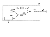
- FIG. 14 is a diagram illustrating a schematic configuration of the termination portion 137 according to Configuration Example 3.
- the termination unit 137 according to the configuration example 3 includes a wavelength division multiplexing optical multiplexer / demultiplexer 132a, a visible light emitting unit 133a, an optical multiplexer / demultiplexer 135a, a photodetector 136a, and a return light attenuation module 140.
- the visible light emitting unit 133a is a light source for outputting guide light G for confirming the position where the output laser light is irradiated.
- the wavelength division multiplexing optical multiplexer / demultiplexer 132a includes an optical fiber through which the return light R propagates, an optical fiber to which the visible light emitting unit 133a is connected, and an optical fiber to which the optical multiplexer / demultiplexer 135a is connected. It is a device for wavelength-selective optical multiplexing / demultiplexing.
- the wavelength division multiplexing optical multiplexer / demultiplexer 132a has a wavelength characteristic that allows the guide light G output from the visible light emitting unit 133a to pass through the optical fiber through which the return light R propagates with low loss.
- the wavelength division multiplexing optical multiplexer / demultiplexer 132a has a wavelength characteristic that allows the return light R to pass through the optical fiber to which the optical multiplexer / demultiplexer 135a is connected with low loss.
- the wavelength division multiplexing optical multiplexer / demultiplexer 132a has a wavelength characteristic that greatly attenuates the return light R when it passes through the optical fiber to which the visible light emitting unit 133a is connected.
- the optical multiplexer / demultiplexer 135a is a so-called Tap coupler, which is connected to the optical fiber through which the return light R propagates, the optical fiber to which the photodetector 136a is connected, and the return light attenuation module 140. It is a device for optical multiplexing / demultiplexing while adjusting the light intensity ratio with the optical fiber.
- the photodetector 136a can monitor the light intensity of the return light R propagating through the output optical fiber in the direction opposite to the output laser light.
- the termination unit 137 irradiates at least the return light attenuation module 140 that attenuates the return light R that propagates through the output optical fiber 120 in the direction opposite to the output laser light, and the output laser light.
- a visible light emitting unit 133a for outputting a guide light G for confirming the position of the light, and light detection for monitoring the light intensity of the return light R propagating through the output optical fiber in the direction opposite to the output laser light.
- Device 136a is irradiates at least the return light attenuation module 140 that attenuates the return light R that propagates through the output optical fiber 120 in the direction opposite to the output laser light, and the output laser light.
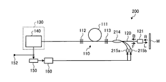
- FIG. 15 is a diagram showing a schematic configuration of an optical fiber laser device 200 according to the second embodiment of the present invention.
- the optical fiber laser device 200 according to the second embodiment of the present invention is an optical fiber laser type device that generates laser light using an amplification optical fiber 111 as an amplification medium in a laser oscillator 110. is there.
- the optical fiber laser device 200 employs a so-called backward pumping configuration. That is, in the optical fiber laser device 200, pumping light is introduced backward with respect to the laser oscillator 110. Therefore, the optical fiber laser device 200 combines the pumping light output from the pumping laser diodes 215a and 215b at the subsequent stage of the second light reflector 113 and outputs the pumping light to the second light reflector 113.
- An excitation light multiplexer 214 is provided.
- the excitation light multiplexer 214 is configured by TFB, for example, as in the first embodiment.
- the pumping light port of the pumping light combiner 214 is connected to the pumping laser diodes 215 a and 215 b, and the reverse signal port of the pumping light combiner 214 is the second light reflector 113. It is connected to the.
- the forward signal port of the excitation light multiplexer 214 is connected to the output optical fiber 120.
- the termination unit 130 is connected to the first light reflector 112. In addition, when there is a surplus port in the pumping light port of the pumping light multiplexer 214, the termination unit 130 may be connected to the surplus port.
- the optical fiber laser device 200 takes into account not only the intensity of the return light but also the time during which the situation in which the intensity of the return light is high continues, The amount can be determined.
- the control unit 160 can control the outputs of the excitation laser diodes 215a and 215b based on the amount of load received by the optical fiber in the termination unit 130. As a result, whether or not to suppress the output laser light output from the optical fiber laser device 200 is optimized, and unnecessary suppression of the output laser light is reduced. As a result, high durability and high output performance of the optical fiber laser device 200 are realized.
- FIG. 16 is a diagram showing a schematic configuration of an optical fiber laser apparatus 300 according to the third embodiment of the present invention.
- an optical fiber laser apparatus 300 according to the third embodiment of the present invention is an optical fiber laser type apparatus that generates laser light using an amplification optical fiber 111 as an amplification medium in a laser oscillator 110. is there.
- the optical fiber laser apparatus 300 employs a so-called bidirectional excitation type configuration. That is, in the optical fiber laser device 300, the pump light is introduced into the laser oscillator 110 in the front and the pump light is introduced in the rear. Therefore, the optical fiber laser device 300 combines the pumping light output from the pumping laser diodes 315c and 315d before the first light reflector 112, and outputs the pumping light to the first light reflector 112. Pumping light combiner 314a for combining the pumping light output from pumping laser diodes 315a and 315b in the subsequent stage of second light reflector 113, and outputting the pumping light to second light reflector 113 A pumping light multiplexer 314b is provided.
- the excitation light multiplexers 314a and 314b are configured by, for example, TFB, as in the first embodiment.
- the pumping light port of the pumping light multiplexer 314a is connected to the pumping laser diodes 315a and 315b, and the forward signal port of the pumping light multiplexer 314a is the first light reflector 112. It is connected to the.
- the pumping light port of the pumping light multiplexer 314b is connected to the pumping laser diodes 315c and 315d, and the reverse signal port of the pumping light multiplexer 314b is connected to the second light reflector 113.
- the forward signal port of the pumping light multiplexer 314b is connected to the output optical fiber 120.
- the reverse direction signal port of the excitation light multiplexer 314 a is connected to the termination unit 130.
- terminus part 130 is not limited to what is connected to the reverse direction signal port of the excitation light multiplexer 314a similarly to 1st Embodiment. It is also possible to adopt a configuration in which the termination unit 130 is connected to so-called surplus ports of the pumping light multiplexers 314a and 314b.
- the optical fiber laser device 300 takes into account not only the intensity of the return light but also the time during which the situation where the intensity of the return light is high continues, The amount can be determined. Then, the control unit 160 can control the outputs of the excitation laser diodes 315a, 315b, 315c, and 315d based on the amount of load received by the optical fiber in the termination unit 130. As a result, the determination as to whether or not to suppress the output laser output from the optical fiber laser device 300 is made appropriate, and the suppression of unnecessary output laser light is reduced. As a result, high durability and high output performance of the optical fiber laser device 300 are realized.
- FIG. 17 is a diagram showing a schematic configuration of an optical fiber laser device 400 according to the fourth embodiment of the present invention.
- an optical fiber laser device 400 according to the fourth embodiment of the present invention is an optical fiber laser type device that generates laser using an amplification optical fiber 111 as an amplification medium in a laser oscillator 110. .
- the optical fiber laser device 400 employs a so-called forward pumping type configuration.
- the optical fiber laser device 400 introduces pumping light forward from the rear stage of the first light reflector 112 toward the amplification optical fiber 111.
- the excitation light output from the excitation laser diodes 415a and 415b is multiplexed, and the excitation light is output in the direction of the amplification optical fiber 111.
- An excitation light multiplexer 414 is provided.
- the excitation light multiplexer 414 is configured by TFB, for example, as in the first embodiment.
- the pumping light port of the pumping light multiplexer 414 is connected to the pumping laser diodes 415a and 415b, and the forward signal port of the pumping light multiplexer 414 is connected to the amplification optical fiber 111.
- the reverse signal port of the excitation light multiplexer 414 is connected to the first light reflector 112.
- the termination unit 130 is connected to the first light reflector 112. If there is a surplus port in the pumping light port of the pumping light multiplexer 414, the termination unit 130 may be connected to the surplus port.
- the control unit 160 can control the outputs of the excitation laser diodes 415a and 415b based on the amount of load received by the optical fiber in the termination unit 130. As a result, whether or not to suppress the output laser light output from the optical fiber laser device 400 is optimized, and unnecessary suppression of the output laser light is reduced. As a result, high durability and high output performance of the optical fiber laser device 400 are realized.
- FIG. 18 is a diagram showing a schematic configuration of an optical fiber laser device 500 according to the fifth embodiment of the present invention.
- an optical fiber laser device 500 according to the fifth embodiment of the present invention is an optical fiber laser type device that generates laser using an amplification optical fiber 111 as an amplification medium in a laser oscillator 110. .
- the optical fiber laser device 500 employs a so-called backward pumping configuration.
- the optical fiber laser device 500 introduces pumping light backward from the front stage of the second light reflector 113 toward the amplification optical fiber 111.
- the excitation light output from the excitation laser diodes 515a and 515b is multiplexed, and the excitation light is output in the direction of the amplification optical fiber 111.
- An excitation light multiplexer 514 is provided.
- the excitation light multiplexer 514 is configured by TFB, for example, as in the first embodiment.
- the pumping light port of the pumping light multiplexer 514 is connected to the pumping laser diodes 515 a and 515 b, and the reverse signal port of the pumping light multiplexer 514 is connected to the amplification optical fiber 111.
- the forward signal port of the excitation light multiplexer 514 is connected to the output optical fiber 120 via the second light reflector 113.
- the termination unit 130 is connected to the first light reflector 112. In addition, when there is a surplus port in the pumping light port of the pumping light multiplexer 514, the termination unit 130 may be connected to the surplus port.
- the optical fiber laser device 500 takes into account not only the intensity of the return light but also the time during which the situation where the intensity of the return light is high continues, The amount can be determined. Then, the control unit 160 can control the outputs of the excitation laser diodes 515a and 515b based on the amount of load received by the optical fiber in the termination unit 130. As a result, whether or not to suppress the output laser output from the optical fiber laser device 500 is optimized, and unnecessary suppression of the output laser is reduced. As a result, high durability and high output performance of the optical fiber laser device 500 are realized.
- FIG. 19 is a diagram showing a schematic configuration of an optical fiber laser apparatus 600 according to the sixth embodiment of the present invention.
- an optical fiber laser apparatus 600 according to the sixth embodiment of the present invention is an optical fiber laser type apparatus that generates laser light using an amplification optical fiber 111 as an amplification medium in a laser oscillator 110. is there.
- the optical fiber laser apparatus 600 employs a so-called bidirectional excitation type configuration.
- the optical fiber laser device 600 introduces pumping light forward from the rear stage of the first light reflector 112 toward the amplification optical fiber 111 and also reflects the second light. Pump light is introduced backward from the front stage of the device 113 toward the amplification optical fiber 111. Between the first optical reflector 112 and the amplification optical fiber 111, the excitation light output from the excitation laser diodes 615a and 615b is multiplexed, and the excitation light is output toward the amplification optical fiber 111. An excitation light multiplexer 614a is provided.
- the excitation light output from the excitation laser diodes 615c and 615d is multiplexed, and the excitation light is output in the direction of the amplification optical fiber 111.
- An excitation light multiplexer 614b is provided.
- the excitation light multiplexers 614a and 614b are configured by TFB, for example, as in the first embodiment.
- the pumping light port of the pumping light multiplexer 614a is connected to the pumping laser diodes 615a and 615b, and the forward signal port of the pumping light multiplexer 614a is connected to the amplification optical fiber 111.
- the reverse signal port of the pumping light multiplexer 614 a is connected to the first light reflector 112.
- the pumping light port of the pumping light multiplexer 614b is connected to the pumping laser diodes 615c and 615d, and the reverse signal port of the pumping light multiplexer 614b is the amplification optical fiber 111. It is connected to the.
- the forward direction signal port of the pumping light multiplexer 614 b is connected to the output optical fiber 120.
- the termination unit 130 is connected to the first light reflector 112. In addition, when a surplus port exists in the pumping light ports of the pumping light multiplexers 614a and 614b, the termination unit 130 may be connected to the surplus port.
- the control unit 160 can control the output of the excitation laser diodes 615a, 615b, 615c, and 615d based on the amount of load received by the optical fiber in the termination unit 130. As a result, whether or not to suppress the output laser light output from the optical fiber laser device 600 is optimized, and unnecessary suppression of the output laser light is reduced. As a result, high durability and high output performance of the optical fiber laser device 600 are realized.
- FIG. 20 is a diagram showing a schematic configuration of an optical fiber laser apparatus 700 according to the seventh embodiment of the present invention.
- an optical fiber laser apparatus 700 according to the seventh embodiment of the present invention generates laser light using an amplification optical fiber 111 as an amplification medium in a laser oscillator 110, and serves as an amplification medium in an optical amplifier. It has a MOPA (Master Oscillator Power-Amplifier) structure in which laser light is amplified using an amplification optical fiber 716.
- MOPA Master Oscillator Power-Amplifier
- an optical fiber laser device 700 according to the seventh embodiment of the present invention has a configuration in which new components are added to the configuration of the optical fiber laser device 100 according to the first embodiment. Therefore, only the newly added components will be described here.
- an optical fiber laser device 700 includes an amplification optical fiber 716 that functions as an amplification medium of an optical amplifier between a laser oscillator 110 and an irradiation head 121. Yes. Further, between the amplification optical fiber 716 and the second optical reflector 113, the excitation light output from the excitation laser diodes 718a and 718b is multiplexed, and the excitation light is output in the direction of the amplification optical fiber 716. An excitation light multiplexer 717 is provided.
- the excitation light multiplexer 717 is configured by, for example, TFB, similarly to the excitation light multiplexer 114.
- the pumping light port of the pumping light multiplexer 717 is connected to the pumping laser diodes 718a and 718b, and the forward signal port of the pumping light multiplexer 717 is connected to the amplification optical fiber 716.
- the reverse direction signal port of the excitation light multiplexer 717 is connected to the second light reflector 113.
- the termination unit 130 may be connected to the surplus port.
- Yb ions which are amplification substances, are added to a core portion made of silica glass, and an inner cladding layer made of quartz glass and a resin are formed on the outer periphery of the core portion.
- This is a double clad type optical fiber in which an outer clad layer made of, etc. is sequentially formed.
- the optical fiber laser device 700 can amplify the laser light oscillated by the laser oscillator 110 by the amplification optical fiber 716 and output it to the output optical fiber 120.
- the optical fiber laser device 700 takes into account not only the intensity of the return light but also the time during which the situation where the intensity of the return light is high continues, The amount can be determined by the controller 160.
- the control unit 160 can control the outputs of the excitation laser diodes 115a and 115b and / or the excitation laser diodes 718a and 718b based on the amount of load received by the optical fiber in the termination unit 130. As a result, the determination as to whether or not to suppress the output laser light output from the optical fiber laser device 700 is made appropriate, and the suppression of unnecessary output laser light is reduced. As a result, high durability and high output performance of the optical fiber laser device 700 are realized.
- the optical fiber laser device 700 according to the seventh embodiment described above has a configuration in which an amplification optical fiber 716 and a pumping light multiplexer 717 are added to the optical fiber laser device 100 according to the first embodiment.
- An amplification optical fiber 716 and a pumping light multiplexer 717 may be added to the optical fiber laser devices 200, 300, 400, 500, and 600 of the sixth embodiment.
- FIG. 21 is a diagram showing a schematic configuration of an optical fiber laser apparatus 800 according to the eighth embodiment of the present invention.
- an optical fiber laser device 800 according to the eighth embodiment of the present invention generates laser light using an amplification optical fiber 111 as an amplification medium in a laser oscillator 110, and serves as an amplification medium in an optical amplifier. It has a MOPA structure in which laser light is amplified using an amplification optical fiber 816.
- an optical fiber laser device 800 according to the eighth embodiment of the present invention has a configuration in which new components are added to the configuration of the optical fiber laser device 100 according to the first embodiment. Therefore, only the newly added components will be described here.
- an optical fiber laser device 800 includes an amplification optical fiber 816 that functions as an amplification medium of an optical amplifier between a laser oscillator 110 and an irradiation head 121. Yes. Further, between the amplification optical fiber 816 and the output optical fiber 120, the excitation light output from the excitation laser diodes 818a and 818b is multiplexed, and the excitation light is output in the direction of the amplification optical fiber 816. An excitation light multiplexer 817 is provided.
- the excitation light multiplexer 817 is configured by, for example, TFB, similarly to the excitation light multiplexer 114.
- the pumping light port of the pumping light multiplexer 817 is connected to the pumping laser diodes 818 a and 818 b, and the reverse direction signal port of the pumping light multiplexer 817 is connected to the amplification optical fiber 816.
- the forward signal port of the pumping light multiplexer 817 is connected to the output optical fiber 120.
- the termination unit 130 may be connected to the surplus port.
- Yb ions which are amplification substances, are added to a core portion made of silica glass, and an inner cladding layer made of quartz glass and a resin are formed on the outer periphery of the core portion.
- This is a double clad type optical fiber in which an outer clad layer made of, etc. is sequentially formed.
- the optical fiber laser device 800 can amplify the laser light oscillated by the laser oscillator 110 by the amplification optical fiber 816 and output it to the output optical fiber 120.
- the optical fiber laser device 800 takes into account not only the intensity of the return light but also the time during which the situation where the intensity of the return light is high continues, The amount can be determined by the controller 160.
- the control unit 160 can control the outputs of the excitation laser diodes 115a and 115b and / or the excitation laser diodes 818a and 818b based on the amount of load received by the optical fiber in the termination unit 130. As a result, whether or not to suppress the output laser beam output from the optical fiber laser device 800 is optimized, and unnecessary suppression of the output laser beam is reduced. As a result, high durability and high output performance of the optical fiber laser device 800 are realized.
- the optical fiber laser device 800 of the eighth embodiment described above has a configuration in which an amplification optical fiber 816 and a pumping light multiplexer 817 are added to the optical fiber laser device 100 of the first embodiment.
- An amplification optical fiber 816 and a pumping light multiplexer 817 may be added to the optical fiber laser devices 200, 300, 400, 500, and 600 of the sixth embodiment.
- FIG. 22 is a diagram showing a schematic configuration of an optical fiber laser apparatus 900 according to the ninth embodiment of the present invention.
- an optical fiber laser device 900 according to the ninth embodiment of the present invention generates laser light using an amplification optical fiber 111 as an amplification medium in a laser oscillator 110, and serves as an amplification medium in an optical amplifier. It has a MOPA structure in which laser light is amplified using an amplification optical fiber 916.
- the optical fiber laser device 900 according to the ninth embodiment of the present invention has a configuration in which new components are added to the configuration of the optical fiber laser device 100 according to the first embodiment. Therefore, only the newly added components will be described here.
- an optical fiber laser device 900 includes an amplification optical fiber 916 that functions as an amplification medium of an optical amplifier between a laser oscillator 110 and an irradiation head 121. Yes. Further, between the amplification optical fiber 916 and the second optical reflector 113, the excitation light output from the excitation laser diodes 918a and 918b is multiplexed, and the excitation light is output in the direction of the amplification optical fiber 916. An excitation light multiplexer 917a is provided.
- the excitation light output from the excitation laser diodes 918c and 918d is multiplexed, and the excitation light is output in the direction of the amplification optical fiber 916.
- An excitation light multiplexer 917b is provided.
- the pumping light multiplexers 917a and 917b are configured by, for example, TFB, similarly to the pumping light multiplexer 114.
- the pumping light port of the pumping light multiplexer 917a is connected to the pumping laser diodes 918a and 918b, and the forward signal port of the pumping light multiplexer 917a is connected to the amplification optical fiber 916.
- the reverse direction signal port of the pumping light multiplexer 917 a is connected to the second light reflector 113.
- the pumping light port of the pumping light multiplexer 917b is connected to the pumping laser diodes 918c and 918d, and the reverse direction signal port of the pumping light multiplexer 917b is the amplification optical fiber 916. It is connected to the.
- the forward signal port of the pumping light multiplexer 917 b is connected to the output optical fiber 120.
- the termination unit 130 may be connected to the surplus port.
- amplification optical fiber 916 similarly to the amplification optical fiber 111, Yb ions as an amplification substance are added to a core portion made of quartz glass, and an inner cladding layer made of quartz glass and a resin are formed on the outer periphery of the core portion.
- This is a double clad type optical fiber in which an outer clad layer made of, etc. is sequentially formed.
- the optical fiber laser device 900 can amplify the laser light oscillated by the laser oscillator 110 by the amplification optical fiber 916 and output it to the output optical fiber 120.
- the optical fiber laser apparatus 900 takes into account not only the intensity of the return light but also the time during which the situation where the intensity of the return light is high continues, The amount can be determined by the controller 160.
- the control unit 160 can control the outputs of the excitation laser diodes 115a and 115b and / or the excitation laser diodes 918a, 918b, 918c, and 918d based on the amount of load received by the optical fiber at the termination unit 130. .
- the determination as to whether or not to suppress the output laser light output from the optical fiber laser device 900 is made appropriate, and the suppression of unnecessary output laser light is reduced.
- high durability and high output performance of the optical fiber laser apparatus 900 are realized.
- the optical fiber laser device 900 of the ninth embodiment described above is configured such that an amplification optical fiber 916 and pumping light multiplexers 917a and 917b are added to the optical fiber laser device 100 of the first embodiment.
- An amplification optical fiber 916 and pumping light combiners 917a and 917b may be added to the optical fiber laser devices 200, 300, 400, 500, and 600 of the second to sixth embodiments.
- FIG. 23 is a diagram showing a schematic configuration of an optical fiber laser apparatus 1000 according to the tenth embodiment of the present invention.
- an optical fiber laser apparatus 1000 according to the tenth embodiment of the present invention generates laser light using an amplification optical fiber 111 as an amplification medium in a laser oscillator 110, and serves as an amplification medium in an optical amplifier. It has a MOPA structure in which laser light is amplified using an amplification optical fiber 716.
- the optical fiber laser apparatus 1000 according to the tenth embodiment of the present invention has a configuration in which new components are added to the configuration of the optical fiber laser apparatus 700 according to the seventh embodiment. Therefore, only the newly added components will be described here.
- a wavelength division multiplexing optical multiplexer / demultiplexer 1031 is inserted between the amplification optical fiber 716 and the irradiation head 121, and the amplification optical fiber 716, the irradiation head 121, and the like.
- the optical fiber between is branched.
- the branched optical fiber is connected to the terminal end 1030.
- the termination unit 1030 includes a wavelength division multiplexing optical multiplexer / demultiplexer 1032, a visible light emitting unit 1033, and a return light attenuation module 140. That is, the configuration of the termination unit 1030 is the same as that of the termination unit 131 according to Configuration Example 1 described above. Therefore, although description of each structure of the termination
- the termination unit 1030 includes a return light attenuation module 140 that attenuates return light R that propagates through the output optical fiber in a direction opposite to the output laser light, and guide light for confirming the position where the output laser light is irradiated. And a visible light emitting unit 1033 for outputting.
- the optical fiber laser apparatus 1000 of the tenth embodiment considers not only the intensity of the return light but also the time during which the situation where the intensity of the return light is high continues, the amount of load received by the optical fiber at the termination unit 1030 is controlled by the control unit. 160 can determine. Then, the control unit 160 can control the outputs of the excitation laser diodes 115a and 115b and / or the excitation laser diodes 718a and 718b based on the amount of load received by the optical fiber in the termination unit 1030. As a result, the determination as to whether or not to suppress the output laser output from the optical fiber laser apparatus 1000 is made appropriate, and the suppression of unnecessary output laser light is reduced. As a result, high durability and high output performance of the optical fiber laser apparatus 1000 are realized.
- optical fiber laser apparatus 1000 of 10th Embodiment described above is the structure which adds the termination
- FIG. 24 is a diagram showing a schematic configuration of an optical fiber laser apparatus 1100 according to the eleventh embodiment of the present invention.
- an optical fiber laser device 1100 according to an eleventh embodiment of the present invention generates laser light using an amplification optical fiber 111 as an amplification medium in a laser oscillator 110, and serves as an amplification medium in an optical amplifier. It has a MOPA structure in which laser light is amplified using an amplification optical fiber 716.
- an optical fiber laser device 1100 according to the eleventh embodiment of the present invention has a configuration in which new components are added to the configuration of the optical fiber laser device 700 according to the seventh embodiment. Therefore, only the newly added components will be described here.
- an optical multiplexer / demultiplexer 1131 is inserted between the amplification optical fiber 716 and the irradiation head 121, and between the amplification optical fiber 716 and the irradiation head 121.
- the optical fiber is branched.
- the branched optical fiber is connected to the terminal end 1130.
- the termination unit 1130 includes an optical multiplexer / demultiplexer 1132, a photodetector 1133, and a return light attenuation module 140. That is, the configuration of the termination unit 1130 is the same as the termination unit 134 according to Configuration Example 2 described above. Therefore, although description of each component of the termination
- the terminating unit 1130 includes a return light attenuation module 140 for attenuating the return light R propagating through the output optical fiber in the direction opposite to the output laser light, and a return propagating through the output optical fiber in the direction opposite to the output laser light. And a photodetector 1133 for monitoring the light intensity of the light R.
- the optical fiber laser apparatus 1100 of the eleventh embodiment considers not only the intensity of the return light but also the time during which the situation where the intensity of the return light is high continues, the amount of load received by the optical fiber at the termination unit 1130 is controlled. 160 can determine.
- the control unit 160 can control the outputs of the excitation laser diodes 115a and 115b and / or the excitation laser diodes 718a and 718b based on the amount of load received by the optical fiber in the termination unit 1130.
- whether or not to suppress the output laser light output from the optical fiber laser device 1100 is optimized, and the suppression of unnecessary output laser light is reduced.
- high durability and high output performance of the optical fiber laser device 1100 are realized.
- the optical fiber laser device 1100 according to the eleventh embodiment described above has a configuration in which a terminal portion 1130 is added to the optical fiber laser device 700 according to the seventh embodiment, but is different from the optical fiber laser devices according to other embodiments. Thus, it is also possible to add a terminal portion 1130 in the same manner.
- FIG. 25 is a diagram showing a schematic configuration of an optical fiber laser apparatus 1200 according to the twelfth embodiment of the present invention.
- an optical fiber laser device 1200 according to the twelfth embodiment of the present invention generates laser light using an amplification optical fiber 111 as an amplification medium in a laser oscillator 110, and uses it as an amplification medium in an optical amplifier. It has a MOPA structure in which laser light is amplified using an amplification optical fiber 716.
- the optical fiber laser device 1200 according to the twelfth embodiment of the present invention has a configuration in which new components are added to the configuration of the optical fiber laser device 700 according to the seventh embodiment. Therefore, only the newly added components will be described here.
- an optical multiplexer / demultiplexer 1231 is inserted between the amplification optical fiber 716 and the irradiation head 121, and between the amplification optical fiber 716 and the irradiation head 121.
- the optical fiber is branched.
- the branched optical fiber is connected to the terminal end 1230.
- a wavelength division optical multiplexer / demultiplexer may be used instead of the optical multiplexer / demultiplexer 1231.
- the termination unit 1230 includes a wavelength division multiplexing optical multiplexer / demultiplexer 1232, a visible light emitting unit 1233, an optical multiplexer / demultiplexer 1234, a photodetector 1235, and a return light attenuation module 140. That is, the configuration of the termination unit 1230 is the same as the termination unit 137 according to Configuration Example 3 described above. Therefore, although description of each structure of the termination
- the termination unit 1230 includes a return light attenuation module 140 that attenuates return light R propagating through the output optical fiber in a direction opposite to the output laser light, and guide light for confirming the position where the output laser light is irradiated. And a light detector 1235 for monitoring the light intensity of the return light R propagating through the output optical fiber in the direction opposite to the output laser light.
- the optical fiber laser apparatus 1200 considers not only the intensity of the return light but also the time during which the situation where the intensity of the return light is high continues, and controls the amount of load received by the optical fiber at the terminal end 1230. 160 can determine. Then, the control unit 160 can control the output of the excitation laser diodes 115a and 115b and / or the excitation laser diodes 718a and 718b based on the amount of load received by the optical fiber in the termination unit 1230. As a result, whether or not to suppress the output laser beam output from the optical fiber laser device 1200 is optimized, and unnecessary suppression of the output laser beam is reduced. As a result, high durability and high output performance of the optical fiber laser apparatus 1200 are realized.
- the optical fiber laser device 1200 of the twelfth embodiment described above has a configuration in which a terminal end 1230 is added to the optical fiber laser device 700 of the seventh embodiment, but is different from the optical fiber laser devices of other embodiments. It is also possible to adopt a configuration in which the end portion 1230 is similarly added.
- FIG. 26 is a diagram showing a schematic configuration of an optical fiber laser apparatus 1300 according to the thirteenth embodiment.
- an optical fiber laser device 1300 according to the thirteenth embodiment is an optical fiber laser type device that generates output laser light using an amplification optical fiber 111 as an amplification medium in a laser oscillator 110.
- the optical fiber laser apparatus 1300 employs a so-called forward pump type configuration.
- the optical fiber laser device 1300 combines the excitation light output from the excitation laser diodes 115 a and 115 b before the first optical reflector 112 and outputs the excitation light to the amplification optical fiber 111.
- a waver 114 is provided. As a result, the excitation light is introduced from the front stage of the first light reflector 112 toward the amplification optical fiber 111.
- the excitation light multiplexer 114 is configured by, for example, a TFB (Tapered Fiber Bundle).
- the pumping light multiplexer 114 includes a forward direction signal port optical fiber, a backward direction signal port optical fiber, and a plurality of pumping light port optical fibers constituting both ends.
- the pumping light port of the pumping light multiplexer 114 is connected to the pumping laser diodes 115a and 115b.
- the reverse signal port of the excitation light multiplexer 114 is connected to the return light attenuation module 170.
- the forward-side signal port and the backward-side signal port have a core extending at both ends, so that the intensity of the return light is large, and the reverse side of the excitation light multiplexer 114 serves as a port to which the return light attenuation module 170 is connected. A signal port is preferred.
- the return light attenuation module 170 is connected to a visible light emitting unit 180 that introduces visible light in the forward direction via the return light attenuation module 170.
- the return light attenuation module 170 emits attenuated return light from the end opposite to the output optical fiber 120, and the visible light emitting unit 180 is connected to the end.
- FIG. 27 is a diagram showing the configuration of the return light attenuation module 170 and its surroundings.
- the return light attenuation module 170 includes an optical fiber that connects from the reverse direction signal port of the excitation light multiplexer 114 to the visible light emitting unit 180 as a main configuration.
- the return light attenuating module 170 fixes the receiving optical fiber 171 and the attenuating optical fiber 172 included in the returning light attenuating module 170, and the leakage light from the receiving optical fiber 171 and the attenuating optical fiber 172 is converted into heat.
- the metal plate 173 which comprises the heat conversion part for radiating the heat_generation
- the metal plate 173 is made of a metal having high thermal conductivity, and the metal plate 173 itself is also connected to a heat sink or the like in the optical fiber laser device 1300 and is generated from the receiving optical fiber 171 and the attenuation optical fiber 172. It is configured to efficiently exhaust the heat that is generated.
- the receiving optical fiber 171 and the attenuating optical fiber 172 extend from the signal port optical fiber 114a and the visible light emitting unit 180 that extend from the reverse direction signal port of the excitation light multiplexer 114, respectively. It is connected to the pigtail optical fiber 181.
- the signal port optical fiber 114a and the receiving optical fiber 171 are fusion-bonded at a first fusion connection point 174a, and the receiving optical fiber 171 and the attenuation optical fiber 172 are second fusion-bonded.
- the attenuating optical fiber 172 and the pigtail optical fiber 181 are fusion-spliced at a third fusion splicing point 174c.
- the core of the attenuation optical fiber 172 is connected to the core of the optical fiber such as the amplification optical fiber 111 constituting the laser oscillator 110 via the receiving optical fiber 171 and the signal port optical fiber 114a.
- the first fusion splice point 174a is configured to have a small connection loss, for example, the same as the connection loss of the second fusion splice point 174b or smaller than the connection loss of the second fusion splice point 174b. It is preferable. It is preferable in terms of heat management to suppress heat generation at the first fusion splice point 174a and to concentrate heat generation factors on the metal plate 173. It is preferable that the signal port optical fiber 114a and the receiving optical fiber 171 have substantially the same core diameter and NA. The cladding diameter of the receiving optical fiber 171 is preferably greater than or equal to the cladding diameter of the signal port optical fiber 114a.
- the signal port optical fiber 114a and the receiving optical fiber 171 are preferably so-called low index optical fibers.
- the refractive index of the coating is lower than the refractive index of the clad, and the leakage light at the first fusion splice point 174a can be suppressed low, so that heat generation factors are concentrated on the metal plate 173. It contributes to that.
- the receiving optical fiber 171 is preferably selected according to the optical fiber to which the return light attenuation module 170 is connected, for example, the signal port optical fiber 114a in this embodiment.
- the receiving optical fiber 171 may be the same optical fiber as the optical fiber to which the return light attenuation module 170 is connected. In that case, a configuration in which the first fusion splice point 174a is not provided is also possible.
- the signal port optical fiber 114a is a pedestal optical fiber having a core diameter of 14 ⁇ m and a cladding diameter of 125 ⁇ m
- the receiving optical fiber 171 is a double-clad optical fiber having a core diameter of 14 ⁇ m and a cladding diameter of 125 ⁇ m.
- the pedestal optical fiber is an optical fiber having a structure in which a region having a refractive index between the core and the clad is provided around the core.
- the propagation characteristics of the core in the pedestal optical fiber and the double clad optical fiber are substantially single mode as in the optical fiber constituting the laser oscillator 110.
- the second fusion splice point 174b is not necessarily configured to have a connection loss smaller than that of the first fusion splice point 174a. This is because the second fusion splicing point 174b is disposed on the metal plate 173 and can dissipate heat generated by the connection loss. However, when the heat generation at the second fusion splicing point 174b becomes large to some extent, the heat generation may melt the coating of the optical fiber. Therefore, it is preferable to remove the coating of the optical fiber in the vicinity of the second fusion splicing point 174b. Since the attenuation optical fiber 172 generates more heat, it is more preferable to remove the fixed length of the attenuation optical fiber 172 from the second fusion splicing point 174b.
- the options for the attenuation optical fiber 172 are wide.
- the attenuation optical fiber 172 is freely selected so that the bending loss with respect to the return light is larger than the bending loss with respect to the visible light. If the attenuation optical fiber 172 is bent around a plurality of turns and fixed to the metal plate 173, the return light It can function as a return light propagation loss unit made of a medium that continuously gives a loss to the return light in the propagation direction.
- the core of the attenuation optical fiber 172 Since the component of the return light that is a problem in particular propagates in the core mode, the core of the attenuation optical fiber 172 has a loss in the wavelength of the return light with respect to the return light propagating in the core mode. It is preferable that it is larger than the loss in.
- the visible light emitting unit 180 outputs visible laser light such as red or green as visible light, and the visible laser light is transmitted through the return light attenuation module 170, the amplification optical fiber 111, and the output optical fiber 120. Output from the fiber laser device 1300.
- the attenuation optical fiber 172 constituting the return light attenuation module 170 has such a light intensity that the visible laser light output from the optical fiber laser device 1300 can be visually recognized, and the return light attenuation module.
- the length and the bending diameter are set so that the return light composed of infrared light input to 170 is attenuated and output to the visible light emitting unit 180 side.
- the degree of visual recognition is, for example, about JIS C6802 class 2 to 3R.
- the suppression is preferably attenuated to such an extent that the visible light emitting unit 180 is not damaged even when the return light power input to the visible light emitting unit 180 is about 300 W or more or about the same as the output. .
- Visible light has a wavelength of about 400 nm to 800 nm, and the wavelength of output laser light L for processing used for processing is infrared light, which is often 1000 nm or more. Therefore, it is preferable to select an attenuation optical fiber 172 having a bending loss for light having a wavelength of 1000 nm or more larger than that for light having a wavelength of 800 nm or less. For example, when the wavelength of the visible light used as the guide light is 660 nm and the wavelength of the processing output laser light L is 1070 nm, the attenuation optical fiber 172 has a bending loss with respect to the light with the wavelength of 1070 nm. It is more preferable to select one that is larger than the bending loss for light.
- visible light output from the optical fiber laser device 1300 can be visually recognized, and bending loss with respect to return light and bending loss with respect to visible light are suppressed so as to suppress return light to the visible light emitting unit 180.
- the difference is preferably 50 dB or more.
- the difference between the bending loss for the return light and the bending loss for the visible light is 50 dB or more, most of the return light is attenuated in the attenuation optical fiber 172 and thermally converted.
- the return light in which most of the return light is attenuated in the attenuation optical fiber 172 is attenuated to 10 mW or less even if it is 500 W, for example, and only the remaining minute intensity light is output from the attenuation optical fiber 172. Will be.
- the bend edge wavelength of the attenuation optical fiber 172 is shorter than the wavelength of the return light.
- the bend edge wavelength is a wavelength at which an optical fiber that is not bent at a longer wavelength does not propagate the fundamental mode (or the longest wavelength that can propagate the fundamental mode with low loss). That is, if the return light having a wavelength longer than the bend edge wavelength is propagated through the bent attenuation optical fiber 172, the return light receives a strong loss.
- the wavelength of visible light used as the guide light is shorter than the bend edge wavelength of the attenuation optical fiber 172, and is preferably shorter than 100 nm.
- the core of the attenuation optical fiber 172 is configured to propagate at least light used for guide light in visible light substantially in a single mode. This is because loss to the guide light can be reduced. Accordingly, the bend edge wavelength of the attenuation optical fiber 172 is preferably longer than 660 nm, and more preferably longer than 800 nm.
- the bending radius of the attenuating optical fiber 172 is preferably set so that the bending loss with respect to the light used for the guide light is in a range in which visible light output from the optical fiber laser device can be visually recognized as described above.
- the bend radius of the attenuating optical fiber 172 be changed every radius in the range of 150 mm to 30 mm.
- the length of the section in which the attenuation optical fiber 172 is bent can be selected as appropriate according to the amount of return light to be attenuated, and can be, for example, 1 m to 5 m.
- One end of the attenuation optical fiber 172 having the smaller bending radius (the end opposite to the output optical fiber 120) is fusion-bonded to the pigtail optical fiber 181 at the third fusion-connection point.
- the pigtail optical fiber 181 and the attenuation optical fiber 172 can be the same optical fiber. Therefore, a configuration in which the third fusion splice point 174c is not provided is also possible.
- a groove is provided in the metal plate 173 where the receiving optical fiber 171 and the attenuation optical fiber 172 are disposed, and the receiving optical fiber 171 and the attenuation optical fiber 172 are accommodated in the groove and fixed with resin or the like. Not only can the receiving optical fiber 171 and the attenuation optical fiber 172 be securely fixed, but also the effect of efficiently converting the leakage light of the return light leaking from the attenuation optical fiber 172 and exhausting heat can be enhanced. It is.
- the metal plate 173 functions as a heat conversion unit that converts light generated by the loss of the attenuation optical fiber 172 into heat.
- a light receiving element or the like may be arranged at a position where the leakage light of the return light can be received, and the intensity of the return light may be monitored. For example, it is possible to perform stable return light intensity measurement by arranging the light receiving element in the vicinity of the second fusion splicing point 174b or the portion where the return light is incident on the bent portion. Further, for example, a light receiving element may be arranged in the vicinity B of the first fusion splicing point 174 a, and the light receiving element is arranged in the vicinity of the attenuation optical fiber 172 or the vicinity of the return light attenuation module 170. Also good.
- a temperature sensor such as a thermistor on the metal plate 173. This is because the temperature of the metal plate 173 has a correlation with the intensity of the return light and can be used to control the output of the output laser light L while monitoring the intensity of the return light.
- FIG. 28 is a side view of the return light attenuation module 170.
- the light shielding plate 175 is provided substantially parallel to the metal plate 173 by a spacer.
- the light shielding plate 175 may be made of the same material or resin as the metal plate 173.
- the distance between the metal plate 173 and the light shielding plate 175 is, for example, 6 mm, and the attenuation optical fiber 172 is accommodated between the metal plate 173 and the light shielding plate 175.
- the configuration as described above it is possible to suppress the return light leaking from the attenuation optical fiber 172 from being emitted around the return light attenuation module 170. Further, since the return light leaking from the attenuation optical fiber 172 is confined in the return light attenuation module 170, the detection accuracy of the return light when the light receiving element is arranged inside the return light attenuation module 170 is improved. Also, with this configuration, when the temperature sensor is arranged inside the return light attenuation module 170, there is an effect that the temperature gradient with respect to the input power is increased and the sensitivity of the temperature sensor is improved.
- FIG. 29 is a graph showing the temperature of the optical fiber 172 with respect to the input intensity to the return light attenuation module 170
- FIG. 30 is a graph showing the output intensity with respect to the input intensity to the return light attenuation module 170.
- the vertical axis represents temperature [° C.]
- the horizontal axis represents input intensity [W]
- the temperature of the fusion splice point 174b (Point X), attenuation optical fiber 172 (Point Y), and metal plate 173 (Point Z) is plotted.
- the laser light input to the portion corresponding to the first fusion splice point 174a includes pedestal mode and clad mode laser light, and the ratio of the core mode is 70%.
- the second fusion splicing is performed by attaching a temperature sensor to the metal plate 173. The temperatures of the point 174b and the attenuation optical fiber 172 are measured.
- the temperature of the second fusion splicing point 174b, the attenuation optical fiber 172, and the metal plate 173 has a substantially linear characteristic with respect to the input intensity to the return light attenuation module 170.
- the second fusion splice point 174b is 70 ° C. or lower, and the temperature of the metal plate 173 is suppressed to 60 ° C. or lower.
- the left vertical axis is the output intensity [ ⁇ W]
- the horizontal axis is the input intensity [W]
- the right vertical axis is the decibel display [dB]
- the first fusion splice point is a plot of the output intensity at the location corresponding to the third fusion splice point 174c when laser light having a wavelength of 1070 nm is input to the location corresponding to 174a.
- the laser light input to the portion corresponding to the first fusion splice point 174a includes pedestal mode and clad mode laser light, and the ratio of the core mode is 70%.
- the return light attenuation module 170 exhibits an attenuation effect of about 58 dB with respect to the input intensity of 0 W to 600 W.
- the output intensity is suppressed to less than 1 mW even with respect to the input intensity of 600 W. .
- the optical fiber laser apparatus 1300 includes, for example, the return light attenuation module 170 configured by bending the attenuation optical fiber 172 whose bending loss with respect to the return light is larger than the bending loss with respect to the visible light.
- a visible light emitting unit 180 that is connected to the first light reflector 112 via the signal port optical fiber of the optical multiplexer 114 and introduces visible light in the forward direction via the return light attenuation module 170 is provided. Therefore, the optical fiber laser device 1300 described above has a configuration with high durability against return light, and realizes high durability and high output performance.
- FIG. 31 is a diagram showing a schematic configuration of an optical fiber laser device 1400 according to the fourteenth embodiment.
- an optical fiber laser device 1400 according to the fourteenth embodiment is an optical fiber laser type device that generates output laser light using a laser oscillator 110.
- the laser oscillator 110 includes an amplification optical fiber 111 and is configured to generate laser resonance between the first light reflector 112 and the second light reflector 113.
- the output laser light generated by the laser oscillator 110 is irradiated onto the workpiece W as the output laser light L through the output optical fiber 120 and the irradiation head 121.
- the optical fiber laser device 1400 employs a forward pumping type configuration. That is, in the optical fiber laser device 1400, pumping light is introduced in the forward direction with respect to the laser oscillator 110.
- the optical fiber laser device 1400 includes a pumping light multiplexer 114 for introducing pumping light into the laser oscillator 110 before the first light reflector 112.
- the excitation light multiplexer 114 is configured by, for example, TFB as in the first embodiment.
- the pumping light port of the pumping light multiplexer 114 is connected to the pumping laser diodes 115 a and 115 b, and the forward signal port of the pumping light multiplexer 114 is connected to the first light reflector 112.
- the pumping light multiplexer 114 combines the pumping lights output from the pumping laser diodes 115 a and 115 b and outputs the pumping light to the laser oscillator 110.
- the return light attenuation module 170 is connected to a signal port optical fiber extending from the reverse direction signal port of the excitation light multiplexer 114.
- the internal configuration of the return light attenuation module 170 can be the same as that of the first embodiment.
- the optical fiber laser device 1400 includes excitation laser diodes 115a and 115b and a control unit 160 for controlling other control parts.
- a termination processing unit 190 is provided at an end point on the reverse direction side of the return light attenuation module 170.
- the termination processing unit 190 is realized, for example, by applying resin sealing to the termination of the optical fiber constituting the return light attenuation module 170.
- the termination processing unit 190 is illustrated independently of the return light attenuation module 170, but it is also possible to apply resin sealing to the end of the optical fiber inside the return light attenuation module 170.
- FIG. 32 is a diagram illustrating an example of resin sealing at the end of the optical fiber in the termination processing unit 190.
- the termination processing unit 190 includes a sealing member 191 that seals the end of the optical fiber.
- the sealing member 191 is made of resin or the like and has a property of scattering or absorbing return light emitted from the end of the optical fiber.
- the core 192 and the clad 193 at the end of the optical fiber are cut obliquely with respect to the optical axis of the optical fiber. It is preferable to cut the end of the optical fiber obliquely in this way because the amount of light reflected from the end of the optical fiber and returning to the core is reduced. When the intensity of the return light is low, the core 192 and the clad 193 at the end of the optical fiber may be cut perpendicular to the optical axis of the optical fiber.
- a coating 194 is provided around the cladding 193, but the coating 194 is not necessarily required. In consideration of the influence of heat generation, the coating 194 may be peeled off at the end or all of the optical fiber.
- the optical fiber laser apparatus 1400 includes the return light attenuation module 170 configured by bending a plurality of attenuation optical fibers whose bending loss with respect to return light is larger than the bending loss with respect to visible light.
- the signal light is connected to the first light reflector 112 via the signal port optical fiber 114, and the end of the return light attenuation module 170 is sealed with resin. Therefore, the optical fiber laser device 1400 described above has a configuration with high durability against return light, and realizes high durability and high output performance.
- FIG. 33 is a diagram showing a schematic configuration of an optical fiber laser apparatus 1500 according to the fifteenth embodiment.
- an optical fiber laser apparatus 1500 according to the third embodiment is an optical fiber laser type apparatus that generates output laser light by using a laser oscillator 110.
- the laser oscillator 110 includes an amplification optical fiber 111 and is configured to generate laser resonance between the first light reflector 112 and the second light reflector 113.
- the output laser light generated by the laser oscillator 110 is irradiated onto the workpiece W as the output laser light L through the output optical fiber 120 and the irradiation head 121.
- the optical fiber laser device 1500 employs a forward pumping type configuration. That is, in the optical fiber laser device 1500, pumping light is introduced in the forward direction with respect to the laser oscillator 110.
- the optical fiber laser apparatus 1500 is an excitation light multiplexer for introducing excitation light into the laser oscillator 110 between the first optical reflector 112 and the amplification optical fiber 111. 114.
- the excitation light multiplexer 114 is configured by, for example, TFB as in the first embodiment.
- the pumping light port of the pumping light multiplexer 114 is connected to the pumping laser diodes 115 a and 115 b, and the forward signal port of the pumping light multiplexer 114 is connected to the first light reflector 112.
- the pumping light multiplexer 114 combines the pumping lights output from the pumping laser diodes 115 a and 115 b and outputs the pumping light to the laser oscillator 110.
- the pumping light multiplexer 114 combines the pumping lights output from the pumping laser diodes 115 a and 115 b and outputs the pumping light to the laser oscillator 110.
- the reverse signal port of the excitation light multiplexer 114 is connected to the first light reflector 112.
- the optical fiber laser device 1500 includes excitation laser diodes 115a and 115b and a control unit 160 for controlling other control parts.
- the return light attenuation module 170 is connected to an optical fiber extending from the first light reflector 112. Unlike the first embodiment, an optical fiber laser apparatus 1500 according to the fifteenth embodiment has a return light attenuation module 170 connected to the laser oscillator 110 without passing through the pumping light multiplexer 114. However, also in the fifteenth embodiment, the return light attenuation module 170 functions similarly to the first embodiment. A visible light emitting unit 180 that introduces visible light in the forward direction via the return light attenuation module 170 is connected to the return light attenuation module 170.
- the optical fiber laser apparatus 1500 includes the return light attenuation module 170 configured by bending a plurality of attenuation optical fibers whose bending loss with respect to return light is larger than the bending loss with respect to visible light.
- a visible light emitting unit 180 that is connected to the reflector 112 and introduces visible light in the forward direction via the return light attenuation module 170 is provided. Therefore, the optical fiber laser apparatus 1500 described above has a configuration with high durability against return light, and realizes high durability and high output performance.
- FIG. 34 is a diagram showing a schematic configuration of an optical fiber laser apparatus 1600 according to the sixteenth embodiment.
- an optical fiber laser apparatus 1600 according to the sixteenth embodiment is an optical fiber laser type apparatus that generates laser light using a laser oscillator 110.
- the laser oscillator 110 includes an amplification optical fiber 111 and is configured to generate laser resonance between the first light reflector 112 and the second light reflector 113.
- the laser beam generated by the laser oscillator 110 is irradiated onto the workpiece W as the output laser beam L through the output optical fiber 120 and the irradiation head 121.
- the optical fiber laser device 1600 employs a forward pumping type configuration. That is, in the optical fiber laser device 1600, pumping light is introduced in the forward direction with respect to the laser oscillator 110.
- the optical fiber laser device 1600 includes a pumping light multiplexer 114 for introducing pumping light into the laser oscillator 110 before the first light reflector 112.
- the excitation light multiplexer 114 is configured by, for example, TFB as in the first embodiment.
- the pumping light port of the pumping light multiplexer 114 is connected to the pumping laser diodes 115 a and 115 b, and the forward signal port of the pumping light multiplexer 114 is connected to the first light reflector 112.
- the pumping light multiplexer 114 combines the pumping lights output from the pumping laser diodes 115 a and 115 b and outputs the pumping light to the laser oscillator 110.
- the return light attenuation module 170 is connected to a signal port optical fiber extending from the reverse direction signal port of the excitation light multiplexer 114.
- the optical fiber laser device 1600 includes excitation laser diodes 115a and 115b, and a control unit 160 for controlling other control parts.
- the photodetector 136 is connected to the end point on the reverse side of the return light attenuation module 170.
- the photodetector 136 photoelectrically converts the light input via the return light attenuation module 170 and measures the intensity of the return light transmitted through the first light reflector 112 of the laser oscillator 110.
- the intensity of the return light measured by the photodetector 136 is transmitted to the control unit 160.
- the intensity of the return light can be used as an index for determining whether or not the optical fiber laser device 1600 is functioning normally.
- the intensity of the return light may be very strong, and if it is directly input, the photodetector 136 may be damaged. Therefore, the optical fiber laser device 1600 is configured to measure the intensity of the return light appropriately attenuated by the return light attenuation module 170.
- the optical fiber laser device 1600 includes the pumping optical multiplexer including the return light attenuation module 170 configured by bending a plurality of attenuation optical fibers whose bending loss with respect to the return light is larger than the bending loss with respect to the visible light.
- An optical signal detector 136 that performs photoelectric conversion is connected to the end of the return light attenuation module 170 through the signal port optical fiber 114 connected to the first light reflector 112. Therefore, the optical fiber laser device 1600 described above has a configuration with high durability against return light, and realizes high durability and high output performance.
- FIG. 35 is a diagram showing a schematic configuration of an optical fiber laser apparatus 1700 according to the seventeenth embodiment.
- an optical fiber laser apparatus 1700 according to the seventeenth embodiment is an optical fiber laser type apparatus that generates output laser light using a laser oscillator 110.
- the laser oscillator 110 includes an amplification optical fiber 111 and is configured to generate laser resonance between the first light reflector 112 and the second light reflector 113.
- the output laser light generated by the laser oscillator 110 is irradiated onto the workpiece W as the output laser light L through the output optical fiber 120 and the irradiation head 121.
- the optical fiber laser apparatus 1700 employs a forward pumping type configuration. That is, in the optical fiber laser device 1700, pumping light is introduced in the forward direction with respect to the laser oscillator 110.
- the optical fiber laser device 1700 includes a pumping light multiplexer 114 for introducing pumping light into the laser oscillator 110 in front of the first light reflector 112.
- the excitation light multiplexer 114 is configured by, for example, TFB as in the first embodiment.
- the pumping light port of the pumping light multiplexer 114 is connected to the pumping laser diodes 115 a and 115 b, and the forward signal port of the pumping light multiplexer 114 is connected to the first light reflector 112.
- the pumping light multiplexer 114 combines the pumping lights output from the pumping laser diodes 115 a and 115 b and outputs the pumping light to the laser oscillator 110.
- the optical fiber laser apparatus 1700 also includes excitation laser diodes 115a and 115b and a control unit 160 for controlling other control parts.
- the return light attenuation module 170 branches the signal port optical fiber extending from the reverse signal port of the pumping light multiplexer 114 by the optical multiplexer / demultiplexer 1706. Connected first.
- the optical multiplexer / demultiplexer 1706 for example, a so-called Tap coupler or a wavelength division multiplexing optical multiplexer / demultiplexer can be used.
- the Tap coupler demultiplexes the input light with a predetermined intensity ratio without wavelength dependence, and the wavelength division multiplexing optical multiplexer / demultiplexer can demultiplex the input light with a predetermined intensity ratio while having wavelength dependence.
- the return light attenuated by the optical multiplexer / demultiplexer 1706 is input to the return light attenuation module 170.
- a visible light emitting unit 180 that introduces visible light in the forward direction via the return light attenuation module 170 is connected to the return light attenuation module 170.
- the optical fiber laser apparatus 1700 includes the return light attenuation module 170 configured by bending a plurality of attenuation optical fibers whose bending loss with respect to return light is larger than the bending loss with respect to visible light.
- a visible light emitting unit 180 is connected to the first light reflector 112 via the signal port optical fiber 114 and introduces visible light in the forward direction via the return light attenuation module 170. Therefore, the optical fiber laser device 1700 described above has a high durability against return light, and realizes high durability and high output performance.
- FIG. 36 is a diagram showing a schematic configuration of an optical fiber laser apparatus 1800 according to the eighteenth embodiment.
- an optical fiber laser apparatus 1800 according to the eighteenth embodiment is an optical fiber laser type apparatus that generates output laser light using a laser oscillator 110.
- the laser oscillator 110 includes an amplification optical fiber 111 and is configured to generate laser resonance between the first light reflector 112 and the second light reflector 113.
- the output laser light generated by the laser oscillator 110 is irradiated onto the workpiece W as the output laser light L through the output optical fiber 120 and the irradiation head 121.
- the optical fiber laser device 1800 employs a forward pumping type configuration. That is, in the optical fiber laser device 1800, pumping light is introduced in the forward direction with respect to the laser oscillator 110.
- the optical fiber laser device 1800 includes a pumping light multiplexer 114 for introducing pumping light into the laser oscillator 110 before the first light reflector 112.
- the excitation light multiplexer 114 is configured by, for example, TFB as in the first embodiment.
- the pumping light port of the pumping light multiplexer 114 is connected to the pumping laser diodes 115 a and 115 b, and the forward signal port of the pumping light multiplexer 114 is connected to the first light reflector 112.
- the pumping light multiplexer 114 combines the pumping lights output from the pumping laser diodes 115 a and 115 b and outputs the pumping light to the laser oscillator 110.
- the optical fiber laser device 1800 includes excitation laser diodes 115a and 115b and a control unit 160 for controlling other control parts.
- the return light attenuation module 170 is a port to which the pumping laser diodes 115a and 115b among the pumping light ports of the pumping light multiplexer 114 are not connected (so-called surplus port). , And is configured to emit attenuated return light from the end opposite to the output optical fiber 120 (end where the return light is emitted).
- a multimode optical fiber is extended to the pumping light port of the pumping light multiplexer 114.
- this multimode optical fiber has an NA of 0.22, a core diameter of 110 ⁇ m, and a cladding diameter of 125 ⁇ m.
- the same type of multimode optical fiber as the receiving optical fiber of the return light attenuation module 170 so that the connection loss is reduced when the optical fiber is connected to the multimode optical fiber.
- the internal configuration of the return light attenuation module 170 may be the same as that of the first embodiment, but the attenuation optical fiber 172 may be a multimode optical fiber.
- the return light attenuation module 170 is connected to a visible light emitting unit 180 that introduces visible light in the forward direction via the return light attenuation module 170.
- the optical fiber laser apparatus 1800 includes the pumping optical multiplexer including the return light attenuation module 170 configured by bending a plurality of attenuation optical fibers whose bending loss with respect to the return light is larger than the bending loss with respect to the visible light.
- a visible light emitting unit 180 that is connected to the first light reflector 112 via the excitation light port 114 and introduces visible light in the forward direction via the return light attenuation module 170 is provided. Therefore, the optical fiber laser device 1800 described above has a configuration with high durability against return light, and realizes high durability and high output performance.
- FIG. 37 is a diagram showing a schematic configuration of an optical fiber laser apparatus 1900 according to the nineteenth embodiment.
- an optical fiber laser apparatus 1900 according to the nineteenth embodiment is an optical fiber laser type apparatus that generates an output laser beam using a laser oscillator 110.
- the laser oscillator 110 includes an amplification optical fiber 111 and is configured to generate laser resonance between the first light reflector 112 and the second light reflector 113.
- the output laser light generated by the laser oscillator 110 is irradiated onto the workpiece W as the output laser light L through the output optical fiber 120 and the irradiation head 121.
- the optical fiber laser device 1900 employs a so-called backward pumping configuration. That is, in the optical fiber laser device 1900, pumping light is introduced backward with respect to the laser oscillator 110.
- the optical fiber laser apparatus 1900 includes a pumping light multiplexer 114 for introducing pumping light into the laser oscillator 110 after the second light reflector 113.
- the excitation light multiplexer 114 is configured by, for example, TFB as in the first embodiment.
- the pumping light port of the pumping light multiplexer 114 is connected to the pumping laser diodes 115 a and 115 b, and the reverse signal port of the pumping light multiplexer 114 is connected to the second light reflector 113.
- the pumping light multiplexer 114 combines the pumping lights output from the pumping laser diodes 115 a and 115 b and outputs the pumping light to the laser oscillator 110.
- the optical fiber laser apparatus 1900 includes excitation laser diodes 115a and 115b and a control unit 160 for controlling other control parts.
- the return light attenuation module 170 is a port to which the pumping laser diodes 115a and 115b are not connected among the pumping light ports of the pumping light multiplexer 114 (so-called surplus port). , And is configured to emit attenuated return light from the end opposite to the output optical fiber 120 (end where the return light is emitted).
- a multimode optical fiber is extended to the pumping light port of the pumping light multiplexer 114, and the receiving optical fiber of the return light attenuation module 170 has a small connection loss when connected to the multimode optical fiber. It is preferable to be selected as follows.
- the return light attenuation module 170 is connected to a visible light emitting unit 180 that introduces visible light in the forward direction via the return light attenuation module 170.
- the optical fiber laser apparatus 1900 includes the return optical attenuation module 170 configured by bending a plurality of attenuation optical fibers whose bending loss with respect to the return light is larger than the bending loss with respect to the visible light.
- a visible light emitting unit 180 that is connected to the second light reflector 113 via the excitation light port 114 and introduces visible light in the forward direction via the return light attenuation module 170 is provided. Therefore, the above-described optical fiber laser device 1900 has a configuration with high durability against return light, and realizes high durability and high output performance.
- FIG. 38 is a diagram showing a schematic configuration of an optical fiber laser apparatus 2000 according to the twentieth embodiment.
- the optical fiber laser device 2000 according to the twentieth embodiment generates an output laser beam using the laser oscillator 110, and amplifies the output laser beam generated by the laser oscillator 110 with an amplifier 110a.
- This is an optical fiber laser type device having a so-called MOPA (Master Oscillator Power-Amplifier) structure.
- the laser oscillator 110 includes an amplification optical fiber 111 and is configured to generate laser resonance between the first light reflector 112 and the second light reflector 113.
- the output laser light generated by the laser oscillator 110 is amplified by passing through the amplification optical fiber 716 of the amplifier 110a, and is output to the workpiece W as the output laser light L through the output optical fiber 120 and the irradiation head 121. Irradiated.
- the optical fiber laser device 2000 employs a forward pumping type configuration in both the laser oscillator 110 and the amplifier 110a. That is, in the optical fiber laser device 2000, pumping light is introduced in the forward direction with respect to the laser oscillator 110 and the amplifier 110a. Therefore, the optical fiber laser device 2000 includes a first pumping light multiplexer 114 for introducing pumping light into the laser oscillator 110 before the first light reflector 112, and further, a second light reflection. A second pumping light multiplexer 717 for introducing pumping light into the amplifier 110a is provided between the amplifier 113 and the amplification optical fiber 716.
- the first pumping light multiplexer 114 and the second pumping light multiplexer 717 are configured by, for example, TFB as in the first embodiment.
- the pumping light port of the first pumping light multiplexer 114 is connected to the pumping laser diodes 115a and 115b, and the forward signal port of the first pumping light multiplexer 114 is connected to the first light reflector 112. It is connected.
- the first pumping light multiplexer 114 combines the pumping lights output from the pumping laser diodes 115 a and 115 b and outputs the pumping light to the laser oscillator 110.
- the pumping light port of the second pumping light combiner 717 is connected to the pumping laser diodes 718a and 718b, and the reverse direction signal port of the second pumping light combiner 717 is the second light reflector. 113, the reverse direction signal port of the second pumping light multiplexer 717 is connected to the amplification optical fiber 716.
- the second pumping light combiner 717 combines the pumping lights output from the pumping laser diodes 118a and 118b, and outputs the pumping light to the amplifier 110a.
- the return light attenuation module 170 is connected to a signal port optical fiber extending from the reverse direction signal port of the first excitation light multiplexer 114.
- the internal configuration of the return light attenuation module 170 can be the same as that of the first embodiment.
- a visible light emitting unit 180 that introduces visible light in the forward direction via the return light attenuation module 170 is connected to the return light attenuation module 170.
- the optical fiber laser device 2000 includes excitation laser diodes 115a, 115b, 718a, 718b, a visible light emitting unit 180, and a control unit 160 for controlling other control parts.
- the optical fiber laser apparatus 2000 includes the return light attenuation module 170 configured by bending a plurality of attenuation optical fibers whose bending loss with respect to return light is larger than the bending loss with respect to visible light.
- a visible light emitting unit 180 that is connected to the second light reflector 113 via the excitation light port of the optical multiplexer 114 and introduces visible light in the forward direction via the return light attenuation module 170 is provided. Therefore, the optical fiber laser device 2000 described above has a configuration with high durability against return light, and realizes high durability and high output performance.
- FIG. 39 is a diagram showing a schematic configuration of the optical fiber laser apparatus 2100 according to the twenty-first embodiment.
- the optical fiber laser apparatus 2100 according to the twenty-first embodiment is an optical fiber laser type apparatus that generates an output laser beam by using a laser oscillator 110.
- the laser oscillator 110 includes an amplification optical fiber 111 and is configured to generate laser resonance between the first light reflector 112 and the second light reflector 113.
- the output laser light generated by the laser oscillator 110 is irradiated onto the workpiece W as the output laser light L through the output optical fiber 120 and the irradiation head 121.
- the optical fiber laser device 2100 adopts a forward pumping type configuration. That is, in the optical fiber laser device 2100, pumping light is introduced in the forward direction with respect to the laser oscillator 110.
- the optical fiber laser device 2100 includes a pumping light multiplexer 114 for introducing pumping light into the laser oscillator 110 before the first light reflector 112.
- the excitation light multiplexer 114 is configured by, for example, TFB as in the first embodiment.
- the pumping light port of the pumping light multiplexer 114 is connected to the pumping laser diodes 115 a and 115 b, and the forward signal port of the pumping light multiplexer 114 is connected to the first light reflector 112.
- the pumping light multiplexer 114 combines the pumping lights output from the pumping laser diodes 115 a and 115 b and outputs the pumping light to the laser oscillator 110.
- the optical fiber laser device 2100 also includes excitation laser diodes 115a and 115b and a control unit 160 for controlling other control parts.
- an optical multiplexer / demultiplexer 2101 is provided in the middle of the output optical fiber 120, and among the optical fibers branched by the optical multiplexer / demultiplexer 2101, A return light attenuation module 170 is connected, and is configured to emit attenuated return light from an end portion (an end portion from which return light is emitted) opposite to the output optical fiber 120.
- the optical multiplexer / demultiplexer 2101 for example, a so-called Tap coupler, a wavelength division multiplexing optical multiplexer / demultiplexer, or the like can be used, both of which are branched from the optical multiplexer / demultiplexer 2101 to return optical attenuation module 170.
- the return light input to is attenuated, and the visible light output from the visible light emitting unit 180 has an optical branching characteristic such that the visible light is output from the optical fiber laser device 2100 with a visually observable intensity.
- the internal configuration of the return light attenuation module 170 can be the same as that of the first embodiment.
- a visible light emitting unit 180 that introduces visible light in the forward direction via the return light attenuation module 170 is connected to the return light attenuation module 170. Also with the above configuration, visible light emitted from the visible light emitting unit 180 can be used as guide light.
- the optical fiber laser device 2100 includes the return light attenuation module 170 configured by bending a plurality of attenuation optical fibers whose bending loss with respect to return light is larger than the bending loss with respect to visible light, and the return light attenuation module.
- a visible light emitting unit 180 that introduces visible light in the forward direction via 170 is provided. Therefore, the optical fiber laser device 2100 described above has a high durability against return light, and realizes high durability and high output performance.
- FIG. 40 is a diagram showing a schematic configuration of an optical fiber laser apparatus 2200 according to the twenty-second embodiment.
- an optical fiber laser device 2200 according to the twenty-second embodiment is an optical fiber laser type device that generates output laser light using a laser oscillator 110.
- the laser oscillator 110 includes an amplification optical fiber 111 and is configured to generate laser resonance between the first light reflector 112 and the second light reflector 113.
- the output laser light generated by the laser oscillator 110 is irradiated onto the workpiece W as the output laser light L through the output optical fiber 120 and the irradiation head 121.
- the optical fiber laser device 2200 employs a forward pumping type configuration. That is, in the optical fiber laser device 2200, pumping light is introduced in the forward direction with respect to the laser oscillator 110.
- the optical fiber laser device 2200 is provided with a pumping light multiplexer 114 for introducing pumping light into the laser oscillator 110 before the first light reflector 112.
- the excitation light multiplexer 114 is configured by, for example, TFB as in the first embodiment.
- the pumping light port of the pumping light multiplexer 114 is connected to the pumping laser diodes 115 a and 115 b, and the forward signal port of the pumping light multiplexer 114 is connected to the first light reflector 112.
- the pumping light multiplexer 114 combines the pumping lights output from the pumping laser diodes 115 a and 115 b and outputs the pumping light to the laser oscillator 110.
- the optical fiber laser device 2200 includes excitation laser diodes 115a and 115b, and a control unit 160 for controlling other control parts.
- an optical multiplexer / demultiplexer 2201 is provided in the middle of the output optical fiber 120, and among the optical fibers branched by the optical multiplexer / demultiplexer 2201, the optical fiber on the forward direction side is used.
- a return light attenuation module 170 is connected.
- the optical multiplexer / demultiplexer 2201 for example, a so-called Tap coupler or a wavelength division multiplexing optical multiplexer / demultiplexer can be used.
- the internal configuration of the return light attenuation module 170 can be the same as that of the first embodiment.
- a visible light emitting unit 180 that introduces visible light in the forward direction via the return light attenuation module 170 is connected to the return light attenuation module 170.
- visible light emitted from the visible light emitting unit 180 can be used for failure analysis. That is, when it is considered that a failure such as disconnection has occurred in the optical path of the output laser light in the optical fiber laser device 2200, for example, the output optical fiber 120 and the amplification optical fiber 111, the control unit 160 The visible light emitting unit 180 emits light while the operations of the laser diodes 115a and 115b are stopped. Visible light emitted from the visible light emitting unit 180 sequentially propagates through the output optical fiber 120, the amplification optical fiber 111, and the like. If there is a disconnection in this optical path, visible light leaks to the outside at the disconnection location, so that the disconnection location can be identified visually.
- the optical fiber laser apparatus 2200 includes the return light attenuation module 170 configured by bending a plurality of attenuation optical fibers whose bending loss with respect to return light is larger than the bending loss with respect to visible light, and the return light attenuation module.
- a visible light emitting unit 180 that introduces visible light in the forward direction via 170 is provided. Therefore, the optical fiber laser device 2200 described above has a configuration with high durability against return light, and realizes high durability and high output performance.
- FIG. 41 is a diagram showing a schematic configuration of an optical fiber laser apparatus 2300 according to the twenty-third embodiment.
- an optical fiber laser device 2300 according to the twenty-third embodiment includes a plurality of optical fiber laser units 2300 1 ,..., 2300 n ⁇ 1 , 2300 n , and each optical fiber laser unit 2300. 1 ,..., 2300 n ⁇ 1 , 2300 n are combined with an output laser beam by a combiner 2301 and irradiated to the workpiece W as an output laser beam L via the output optical fiber 120 and the irradiation head 121. Is done.
- Each of the optical fiber laser units 2300 1 ,..., 2300 n ⁇ 1 , 2300 n is a virtual optical fiber laser device that is independent of each other. Therefore, as a representative in the following description only the configuration of an optical fiber laser unit 2300 1.
- Optical fiber laser unit 2300 1 is an optical fiber laser type apparatus for generating an output laser beam using a laser oscillator 110.
- the laser oscillator 110 includes an amplification optical fiber 111 and is configured to generate laser resonance between the first light reflector 112 and the second light reflector 113.
- the optical fiber laser unit 2300 1 employs a configuration of a forward pumping type. That is, in the optical fiber laser unit 2300 1, the laser oscillator 110, the forward excitation light has been introduced. Therefore, the optical fiber laser unit 2300 1, in front of the first optical reflector 112, and a pumping light multiplexer 114 for introducing the pumping light to the laser oscillator 110.
- the excitation light multiplexer 114 is configured by, for example, TFB as in the first embodiment.
- the pumping light port of the pumping light multiplexer 114 is connected to the pumping laser diodes 115 a and 115 b, and the forward signal port of the pumping light multiplexer 114 is connected to the first light reflector 112.
- the pumping light multiplexer 114 combines the pumping lights output from the pumping laser diodes 115 a and 115 b and outputs the pumping light to the laser oscillator 110.
- the return light attenuation module 170 is a port to which the optical fiber laser units 1100 1 ,..., 1100 n ⁇ 1 , 1100 n are not connected among the ports of the combiner 2301. , And is configured to emit attenuated return light from the end opposite to the output optical fiber 120 (end where the return light is emitted). Furthermore, a visible light emitting unit 180 that introduces visible light in the forward direction via the return light attenuation module 170 is connected to the return light attenuation module 170. Also with the above configuration, visible light emitted from the visible light emitting unit 180 can be used as guide light.
- the optical fiber laser apparatus 2300 includes the return light attenuation module 170 configured by bending a plurality of attenuation optical fibers whose bending loss with respect to return light is larger than the bending loss with respect to visible light, and the return light attenuation module.
- a visible light emitting unit 180 that introduces visible light in the forward direction via 170 is provided. Therefore, the optical fiber laser apparatus 2300 described above has a configuration with high durability against return light, and realizes high durability and high output performance.
- the embodiment has been described based on the configuration example of the forward-pumped laser oscillator and the amplifier.
- the backward-pumped laser oscillator and the amplifier and the pumping from both the front and the rear are performed.
- the present invention can be appropriately implemented even with a bidirectionally pumped laser oscillator and amplifier.
- only one embodiment having an amplifier is described.
- an amplifier may be added in each embodiment.
- the return light attenuation module is provided in one place for each embodiment, but it goes without saying that a plurality of return light attenuation modules may be provided in one optical fiber laser device.
- a configuration in which a plurality of return light attenuation modules are connected to one port is also included in the scope of the present invention.
- the number of components connected to one return light attenuation module is not limited to one, and it is possible to branch an optical fiber by an optical multiplexer / demultiplexer and to connect a plurality of visible light emitting units and detectors, for example .
- the visible light emitted from the visible light emitting unit is not limited to red (wavelength 660 nm), and green visible light with higher visibility may be used.
- a wavelength-dependent element such as a filter or a lens
- a space coupling type shutter may be introduced into the visible light emitting unit, and the shutter may be closed when the output laser light is oscillated.
- the optical fiber laser device according to the present invention since the optical fiber laser device according to the present invention has a high durability against return light, it is useful as an optical fiber laser device realizing high durability and high output performance.
- Optical fiber laser device 110 Laser oscillator 110a Amplifier 111, 716, 816, 916 Amplifying optical fiber 112 First optical reflector 113 Second optical reflector 114, 214, 314a, 314b, 414, 514, 614a, 614b, 717, 817, 917a , 917b Excitation light multiplexers 115a, 115b, 215a, 215b, 315a, 315b, 315c, 315d, 415a, 415b, 515a, 515b, 615a, 615b, 615c, 615d, 718a, 718b, 818a, 18b, 918a, 918b, 918c, 915d Excitation laser diode 114a Signal port optical fiber
Landscapes
- Physics & Mathematics (AREA)
- Electromagnetism (AREA)
- Engineering & Computer Science (AREA)
- Optics & Photonics (AREA)
- Plasma & Fusion (AREA)
- General Physics & Mathematics (AREA)
- Automation & Control Theory (AREA)
- Lasers (AREA)
- Optical Couplings Of Light Guides (AREA)
- Mechanical Coupling Of Light Guides (AREA)
Abstract
レーザ発振器における増幅媒質に増幅用光ファイバを用いてレーザ光を発生させるファイバレーザ装置において、前記レーザ光を外部へ射出する出力用光ファイバと、少なくとも前記出力用光ファイバを前記レーザ光とは逆方向に伝搬する戻り光を減衰処理する戻り光減衰部と、前記戻り光減衰部に設けられ、前記戻り光を熱に変換する熱変換手段と、前記熱変換手段の発熱に起因する前記戻り光減衰部の温度上昇を測定する温度監視手段と、前記温度監視手段が測定した温度が所定の閾値以上に達した場合に、前記レーザ光の出力を低下または停止する制御部とを備える光ファイバレーザ装置である。
Description
本発明は、光ファイバレーザ装置に関する。
近年、レーザ発振器または光増幅器の光増幅部に光ファイバを用いる光ファイバレーザ装置の利用がレーザ加工等の各分野で広がっている。
このような光ファイバレーザ装置では、レーザ光が反射して光ファイバレーザ装置内の光ファイバのコアに再結合してしまうという、いわゆる戻り光の問題が発生する場合がある(例えば特許文献1または2参照)。この戻り光は、例えば光ファイバレーザ装置をレーザ加工装置として用いる場合には、加工対象に照射したレーザ光が加工対象によって反射されることで発生する。また、光ファイバレーザ装置で使用される光ファイバ内のクラックや、装置内各所の光接続部分での不具合等、様々な場所での反射によっても発生すると考えられる。
この戻り光は、光ファイバレーザ装置内の光ファイバをレーザ発振器が出力するレーザ光とは逆方向に伝搬し、光ファイバレーザ装置の構成部品を破損することがある。戻り光の影響によって破損する光ファイバレーザ装置の構成部品としては、例えば、加工用レーザ光が照射される位置を指し示すガイド光の発光素子が挙げられる。また、戻り光が到達する端部に構成部品が備えられていなくても、端部から強力な戻り光が放出されては安全性確保の観点で問題がある。
しかしながら、上述の戻り光は、質的にも量的にも想定を超えてしまうことがある。例えば、戻り光が光ファイバレーザ装置内の発振器または増幅器を通過することで増幅されてしまうことがある。また、光ファイバレーザ装置内の光ファイバを伝搬する過程で、レーザ発振器が発振させたレーザ光よりも長い波長の誘導ラマン散乱光が発生してしまうこともある。したがって、特定波長の特定強度の戻り光を想定した戻り光対策を採用した場合、戻り光を適切に減衰することができず、光ファイバレーザ装置の構成部品を破損してしまうことがあった。
本発明は、上記に鑑みてなされたものであって、その目的は、高耐久性および高出力性を有する光ファイバレーザ装置を提供することにある。
上述した課題を解決し、目的を達成するために、本発明の一態様に係る光ファイバレーザ装置は、レーザ発振器における増幅媒質に増幅用光ファイバを用いてレーザ光を発生させる光ファイバレーザ装置において、前記レーザ光を外部へ射出する出力用光ファイバと、少なくとも前記出力用光ファイバを前記レーザ光とは逆方向に伝搬する戻り光を減衰処理する戻り光減衰部と、前記戻り光減衰部に設けられ、前記戻り光を熱に変換する熱変換手段と、前記熱変換手段の発熱に起因する前記戻り光減衰部の温度上昇を測定する温度監視手段と、前記温度監視手段が測定した温度が所定の閾値以上に達した場合に、前記レーザ光の出力を低下または停止する制御部とを備えることを特徴とする。
また、本発明の一態様に係る光ファイバレーザ装置は、前記温度監視手段は、前記熱変換手段が発する熱を熱伝導体を介して測定する第1の温度測定点と、前記光ファイバレーザ装置における温度上の基準とみなし得る第2の温度測定点と、の温度差を測定することを特徴とする。
また、本発明の一態様に係る光ファイバレーザ装置は、前記熱変換手段は、前記戻り光減衰部における光ファイバを軸ずれ融着することによって構成されていることを特徴とする。
また、本発明の一態様に係る光ファイバレーザ装置は、前記熱変換手段は、前記戻り光減衰部に設けられた高損失光ファイバで構成されていることを特徴とする。
また、本発明の一態様に係る光ファイバレーザ装置は、前記熱変換手段は、前記戻り光減衰部に設けられた光ファイバを意図的に曲げることによって構成されていることを特徴とする。
また、本発明の一態様に係る光ファイバレーザ装置は、前記熱変換手段は、前記戻り光減衰部に設けられた光ファイバの末端を封止する樹脂で構成されていることを特徴とする。
また、本発明の一態様に係る光ファイバレーザ装置は、前記熱変換手段は、前記戻り光減衰部に設けられた光ファイバの末端から射出された前記戻り光が照射される熱伝導体の照射面で構成されていることを特徴とする。
また、本発明の一態様に係る光ファイバレーザ装置は、前記戻り光減衰部は、前記レーザ光の伝搬方向を前方向として、前記レーザ発振器の前段に配置されていることを特徴とする。
また、本発明の一態様に係る光ファイバレーザ装置は、前記戻り光減衰部は、出力側シグナルポートと入力側シグナルポートと複数の励起光用ポートとを有し、前記励起光用ポートから入力された励起光を前記レーザ発振器に接続されている前記出力側シグナルポートから出力するよう構成した励起光合波器の前記入力側シグナルポートに接続された光ファイバの終端部に設けられていることを特徴とする。
また、本発明の一態様に係る光ファイバレーザ装置は、前記戻り光減衰部は、出力側シグナルポートと入力側シグナルポートと複数の励起光用ポートとを有し、前記励起光用ポートから入力された励起光を前記レーザ発振器に接続されている前記出力側シグナルポートから出力するよう構成した励起光合波器の前記励起光用ポートに接続された光ファイバの終端部に設けられていることを特徴とする。
また、本発明の一態様に係る光ファイバレーザ装置は、前記戻り光減衰部は、前記励起光を出力する光源が接続されていない前記励起光用ポートのうち、前記戻り光の強度が最大となるポートに接続された光ファイバの終端部に設けられていることを特徴とする。
また、本発明の一態様に係る光ファイバレーザ装置は、前記戻り光減衰部は、前記レーザ発振器を構成する2つの光反射器のうち前記レーザ光に対する反射率が高い方の光反射器に接続された光ファイバの終端部に設けられていることを特徴とする。
また、本発明の一態様に係る光ファイバレーザ装置は、前記レーザ発振器と前記出力用光ファイバとの間に設けられ、増幅媒質に増幅用光ファイバを用いた光増幅器と、出力側シグナルポートと入力側シグナルポートと複数の励起光用ポートとを有し、前記励起光用ポートから入力された励起光を前記光増幅器に接続されている前記出力側シグナルポートから出力し、前記光増幅器用の光ファイバへ導入するよう構成した第2の励起光合波器とをさらに備え、前記戻り光減衰部は、前記第2の励起光合波器の励起光用ポートに接続された光ファイバの終端部に設けられていることを特徴とする。
また、本発明の一態様に係る光ファイバレーザ装置は、レーザ発振器における増幅媒質に増幅用光ファイバを用いてレーザ光を発生させる光ファイバレーザ装置において、前記レーザ光を順方向に外部へ導出する出力用光ファイバと、前記出力用光ファイバを前記レーザ光とは逆方向に伝搬する戻り光に対する曲げ損失が可視光に対する曲げ損失よりも大きい減衰用光ファイバを複数周回曲げて構成した戻り光減衰部と、を備えることを特徴とする。
また、本発明の一態様に係る光ファイバレーザ装置は、前記戻り光減衰部は、前記レーザ発振器の高反射率の反射器よりも前段側の光ファイバに接続されていることを特徴とする。
また、本発明の一態様に係る光ファイバレーザ装置は、前記戻り光減衰部は、前記レーザ発振器のレーザ発振に用いる励起光を前記増幅用光ファイバに導入するための励起光合波器のシグナルポート光ファイバを介して、前記反射器よりも逆方向側の光ファイバに接続されていることを特徴とする。
また、本発明の一態様に係る光ファイバレーザ装置は、前記戻り光減衰部は、前記レーザ発振器のレーザ発振に用いる励起光を前記増幅用光ファイバに導入するための励起光合波器の励起光ポートを介して、前記反射器よりも逆方向側の光ファイバに接続されていることを特徴とする。
また、本発明の一態様に係る光ファイバレーザ装置は、前記戻り光減衰部は、前記出力用光ファイバの途中に設けられた光合分波器から分岐された光ファイバに接続されていることを特徴とする。
また、本発明の一態様に係る光ファイバレーザ装置は、前記戻り光減衰部を介して前記可視光を前記出力用光ファイバへ導入する可視光発光部をさらに備えることを特徴とする。
また、本発明の一態様に係る光ファイバレーザ装置は、前記減衰用光ファイバのベンドエッジ波長は、前記戻り光の波長よりも短いことを特徴とする。
また、本発明の一態様に係る光ファイバレーザ装置は、前記減衰用光ファイバは、前記可視光を実質的にシングルモードで伝搬するよう構成されていることを特徴とする。
また、本発明の一態様に係る光ファイバレーザ装置は、前記減衰用光ファイバは、赤色光を実質的にシングルモードで伝搬するよう構成されていることを特徴とする。
また、本発明の一態様に係る光ファイバレーザ装置は、前記戻り光減衰部の終端は、樹脂で封止されていることを特徴とする。
また、本発明の一態様に係る光ファイバレーザ装置は、前記戻り光減衰部の終端に、光電変換を行う光検出器が接続されていることを特徴とする。
また、本発明の一態様に係る光ファイバレーザ装置は、レーザ発振器における増幅媒質に増幅用光ファイバを用いてレーザ光を発生させる光ファイバレーザ装置において、前記レーザ光を順方向に外部へ導出する出力用光ファイバと、前記出力用光ファイバのコアを逆方向に伝搬する、赤外光からなる戻り光の光強度を減衰させて、前記出力用光ファイバとは反対側の端部から減衰した戻り光を出射する戻り光減衰部を備え、前記戻り光減衰部は、前記戻り光の伝搬方向において連続的に該戻り光に損失を与える媒質からなる戻り光伝搬損失部と、該損失によって生じた光を熱に変換する熱変換部を備え、前記戻り光の大部分が前記戻り光伝搬損失部において減衰し熱変換され、減衰後に残留した微小強度の光のみが前記戻り光伝搬損失部の端部から出力されることを特徴とする。
また、本発明の一態様に係る光ファイバレーザ装置は、前記戻り光伝搬損失部は、前記光ファイバレーザ装置の発振器を構成する光ファイバのコアに接続されるコアを有する光ファイバであって、該コアにおいて前記戻り光の大部分が減衰されることを特徴とする。
また、本発明の一態様に係る光ファイバレーザ装置は、前記戻り光伝搬損失部を構成する光ファイバのコアは、前記出力用光ファイバから出力される赤外レーザ光の波長における損失が可視波長域における損失よりも大きいことを特徴とする。
また、本発明の一態様に係る光ファイバレーザ装置は、前記戻り光伝搬損失部を構成する光ファイバのコアは、前記可視波長域においてシングルモード伝搬特性を有することを特徴とする。
また、本発明の一態様に係る光ファイバレーザ装置は、前記戻り光減衰部を介して前記可視光を前記出力用光ファイバへ導入する可視光発光部をさらに備えることを特徴とする。
また、本発明の一態様に係る光ファイバレーザ装置は、前記戻り光減衰部の終端に、光電変換を行う光検出器が接続されていることを特徴とする。
本発明は、上記に鑑みてなされたものであって、その目的は、高耐久性および高出力性を有する光ファイバレーザ装置を提供することにある。
以下、本発明に係る光ファイバレーザ装置の実施形態について、図面を参照しながら詳細に説明する。なお、以下に説明する実施形態により本発明が限定されるものではない。なお、図面において、同一または対応する要素には適宜同一の符号を付している。また、図面は模式的なものであり、各構成の寸法の比率などは現実のものとは異なる場合があることに留意すべきである。また、図面相互間においても互いの寸法の関係や比率が異なる部分が含まれている。また、本明細書においては、カットオフ波長とは、ITU-T(国際電気通信連合)G.650.1で定義する22m法によるカットオフ波長をいう。また、その他、本明細書で特に定義しない用語についてはITU-T G.650.1における定義、測定方法に適宜従うものとする。
(第1実施形態)
図1は、第1実施形態に係る光ファイバレーザ装置100の概略構成を示す図である。図1に示すように、第1実施形態に係る光ファイバレーザ装置100は、レーザ発振器110における増幅媒質に増幅用光ファイバ111を用いてレーザ光を発生させる光ファイバレーザ型の装置である。
図1は、第1実施形態に係る光ファイバレーザ装置100の概略構成を示す図である。図1に示すように、第1実施形態に係る光ファイバレーザ装置100は、レーザ発振器110における増幅媒質に増幅用光ファイバ111を用いてレーザ光を発生させる光ファイバレーザ型の装置である。
光ファイバレーザ装置100は、出力レーザ光Lを順方向(図中矢印F)に外部へ射出する出力用光ファイバ120と、少なくとも出力用光ファイバ120を逆方向(図中矢印B)に伝搬する戻り光Rを減衰処理する戻り光減衰部(減衰モジュール140)と、戻り光減衰モジュール140に設けられ、戻り光を熱に変換する熱変換手段141と、熱変換手段141の発熱に起因する戻り光減衰モジュール140の温度上昇を測定する温度監視手段150と、温度監視手段150が測定した温度が所定の閾値以上に達した場合に、出力レーザ光Lの出力を低下または停止する制御部160とを備えている。なお、以下で説明する実施形態の構成においても、図1に示すように、順方向Fと逆方向Bとを定める。
図1に示すように、レーザ発振器110は、増幅用光ファイバ111と、増幅用光ファイバ111の逆方向側に設けられた第1の光反射器112と、増幅用光ファイバ111の順方向側に設けられた第2の光反射器113と、を備えている。少なくともレーザ発振器110、および、好ましくはその前後を含む出力用光ファイバ120から励起光合波器114のシグナルポート光ファイバまでの各光ファイバは、波長1000nm~1200nmの光を実質的にシングルモード(シングルモード、または、光ファイバのコア中の電界強度分布において大部分が基本モードから構成され、その他数%程度が数次程度の高次モード(a few modes)から構成されるような、モード界分布を有する光)で伝搬する特性のコアを有する光ファイバによって構成されている。以下、実質的にシングルモードとは上記定義された光の伝搬モードのことをいう。また、これらの各光ファイバは、出力レーザ光の波長におけるモードフィールド径が略同一となるように構成されていることが好ましく、少なくともレーザ発振器110を構成する第1の光反射器112から第2の光反射器113を構成する光ファイバにかけてのコアについては、出力レーザ光の波長におけるモードフィールド径が略同一となるように構成され、モード伝搬特性が略同一に構成されているとよい。
増幅用光ファイバ111は、石英系ガラスからなるコア部に増幅物質であるイッテルビウム(Yb)イオンが添加され、コア部の外周には石英系ガラスからなる内側クラッド層と樹脂等からなる外側クラッド層とが順次形成されたダブルクラッド型の光ファイバである。なお、増幅用光ファイバ111のコア部は開口数NA(Numerical Aperture)が例えば0.08であり、波長1000nm~1200nmの光をシングルモードで伝搬するように構成されている。増幅用光ファイバ111の長さは例えば25mである。増幅用光ファイバ111のコア部の吸収係数は、例えば波長1070nmにおいて200dB/mである。また、コア部に入力された励起光から発振するレーザ光へのパワー変換効率は例えば70%である。
第1の光反射器112および第2の光反射器113は、波長特性の異なる例えばファイバブラッググレーティング(Fiber Bragg Grating:FBG)で構成されている。第1の光反射器112および第2の光反射器113は、光ファイバのコアに回折格子を設けることによって構成されている。また、第1の光反射器112および第2の光反射器113は、内側クラッドを有するダブルクラッド型の光ファイバとして構成し、その内側クラッドにて励起光波長の光をマルチモードで伝搬するように構成することが好ましい。
第1の光反射器112は、中心波長が例えば1070nmであり、中心波長およびその周辺の約2nmの幅の波長帯域における反射率が約100%であり、波長915nmの光はほとんど透過する特性を有する。一方、第2の光反射器113は、中心波長が第1の光反射器112と略同じである例えば1070nmであり、中心波長における反射率が10%~30%程度であり、反射波長帯域の半値全幅が約1nmであり、波長915nmの光はほとんど透過する特性を有する。なお、波長915nmの励起光ではなく、例えば波長975nmの励起光を用いる場合、第1の光反射器112および第2の光反射器113は、波長975nmの光はほとんど透過する特性とすることが好ましい。
上記構成により、レーザ発振器110は、波長915nmの励起光が導入された場合に波長1070nmのレーザ光を発振し、当該レーザ光を第2の光反射器113から出力用光ファイバ120へ出力する構成となる。
上記構成により、レーザ発振器110は、波長915nmの励起光が増幅用光ファイバ111に導入された場合に波長1070nmの出力レーザ光を発振し、当該出力レーザ光を第2の光反射器113から出力用光ファイバ120へ出力する構成となる。
光ファイバレーザ装置100をレーザ加工に用いる場合、出力用光ファイバ120へ出力された出力レーザ光Lは、照射ヘッド121を介して加工対象物Wへ照射される。加工対象物Wへ照射された出力レーザ光Lは、加工対象物Wの表面にて反射光を生じ、この反射光の一部が照射ヘッド121を介して出力用光ファイバ120へ導入されることがある。出力用光ファイバ120へ導入された反射光は、出力用光ファイバ120のコアを逆方向に伝搬し、第1の光反射器112を透過することもある。また、反射光によって発生したラマン散乱光や誘導ブリユアン散乱光なども、同様に第1の光反射器112を透過して、終端部130にまで達することがある。したがって、第1の光反射器112を透過する光には複数の成分が含まれることになるが、本明細書では、少なくとも出力用光ファイバ120のコアを出力レーザ光Lとは逆方向に伝搬する光のことを戻り光Rと呼ぶことにする。
図1に示すように、第1実施形態に係る光ファイバレーザ装置100は、いわゆる前方励起型の構成を採用している。光ファイバレーザ装置100には、第1の光反射器112へ励起光を出力するための励起光合波器114が、第1の光反射器112の前段に設けられている。これにより、光ファイバレーザ装置100は、第1の光反射器112の前段から、増幅用光ファイバ111へ向かって励起光を導入する。
励起光合波器114は、例えばTFB(Tapered Fiber Bundle)によって構成されている。励起光合波器114は、両端部を構成する順方向側シグナルポート光ファイバと逆方向側シグナルポート光ファイバと複数の励起光用ポート光ファイバとを備えている。順方向側シグナルポート光ファイバおよび逆方向側シグナルポート光ファイバの間にはコアが延伸しており、該コアはレーザ発振波長においてシングルモード伝搬特性を有することが好ましいが、実質的にシングルモードであってもよい。一方、励起光用ポートは、励起光波長においてマルチモード伝搬特性を有する(マルチモード)コアを備えた光ファイバで構成されている。各励起光用ポートを構成するマルチモード光ファイバは、そのマルチモードコアが順方向側シグナルポートを構成する光ファイバのコアの周りを囲むように構成されている。
励起光合波器114の順方向側シグナルポートは、逆方向側シグナルポートから延伸しているコアがシングルモードコアに、各励起光用ポートから延伸しているコアが内側クラッドに結合するように、ダブルクラッド型の光ファイバに接続されている。さらに、このダブルクラッド型の光ファイバは、第1の光反射器112を介して増幅用光ファイバ111に接続されている。これにより、逆方向側シグナルポートに入力されたレーザ発振波長の光は、実質的にシングルモードで増幅用光ファイバ111のコアに伝搬する。一方、各励起光用ポートに入力された励起波長の光は、マルチモードで増幅用光ファイバ111の内側クラッドに伝搬する。
光ファイバレーザ装置100では、励起光合波器114の励起光用ポートは、励起用レーザダイオード115a,115bに接続されている。
励起光合波器114の逆方向側シグナルポートは、終端部130に接続されている。順方向側シグナルポートと逆方向側シグナルポートとは、両端をコアが延伸しているので、戻り光の強度が大きく、終端部130を接続するポートとして励起光合波器114の逆方向側シグナルポートは好適である。しかしながら、終端部130は、励起光合波器114の逆方向側シグナルポートに接続されるものに限定されない。例えば、励起光合波器114は、複数の励起光用ポートを備えており、すべての励起光用ポートに励起用レーザダイオードが接続されるとは限らない。したがって、励起用レーザダイオードが接続されない、いわゆる余りポートが存在していることもある。このような場合、余りポートの接続先も本実施形態の終端部130となり得る。また、余りポートが複数存在した場合は、それら余りポートの中で戻り光の強度が最大となるものを選択して終端部130の構成を接続することが好ましい。励起光合波器114の逆方向側シグナルポートに他の機器を接続する用途もあり、そのような場合に余りポートの中で戻り光の強度が最大となる励起光用ポートは、終端部130を接続するポートとして好適である。図1には、終端部130は1つのみ記載されているが、光ファイバレーザ装置100に複数の終端部130が存在する可能性もあり、その場合、複数の終端部130のうち少なくとも一つの終端部130にて本発明を適用すればよい。もちろん、複数の終端部130にて同時に本発明を適用することを排除するものではない。
図1に示すように、光ファイバレーザ装置100の終端部130は、戻り光減衰モジュール140を備えている。図1に示される例では、終端部130が戻り光減衰モジュール140のみを備えているが、後に詳述するように、終端部130に他の構成要素を含む構成としてもよい。
図1に示すように、戻り光減衰モジュール140は、励起光合波器114から出力された戻り光を熱に変換する熱変換手段141と、熱変換手段141と接触するように配置され、熱変換手段141が発する熱を伝導する熱伝導体142と、熱伝導体142上に設けられた第1の温度測定点151と、を備えている。第1の温度測定点151は、サーミスタや熱電対等の温度センサを配置する位置である。
熱変換手段141は、後に具体例を挙げて説明するが、戻り光の光エネルギーを熱エネルギーに変換するための手段である。熱伝導体142は、例えば金属プレートで構成されており、熱変換手段141が熱伝導体142上に樹脂等によって固定されている。したがって、熱伝導体142上に設けられた第1の温度測定点151における測定温度は、熱変換手段141が発する熱を適切に反映している。また、熱変換手段141が発する熱は、終端部130における光ファイバが受ける熱的負荷を反映している。結果、熱伝導体142上に設けられた第1の温度測定点151における測定温度は、終端部130における光ファイバが受ける熱的負荷を反映することになる。
温度監視手段150は、第1の温度測定点151に設けられたサーミスタや熱電対等の温度センサから取得した電圧等の電気信号を第1の温度測定点151における温度の情報へ変換する。
光ファイバレーザ装置100では、光ファイバレーザ装置100における温度上の基準とみなし得る第2の温度測定点152に、サーミスタや熱電対等の温度センサを配置することが好ましい。熱伝導体142上に設けられた第1の温度測定点151における測定温度は、終端部130における光ファイバが受ける熱的負荷を反映しているというものの、終端部130における光ファイバの発熱以外の熱的外乱によって影響を受けることがある。したがって、終端部130における光ファイバの発熱以外の熱的な外乱によって、第1の温度測定点151における測定温度が終端部130における光ファイバが受ける熱的負荷を正しく反映できないという状況が発生し得る。
そこで、光ファイバレーザ装置100における温度上の基準とみなし得る第2の温度測定点152に、サーミスタや熱電対等の温度センサを配置し、第1の温度測定点151における温度と第2の温度測定点152における温度との温度差を温度監視手段150にて測定するよう構成する。例えば、第2の温度測定点152として、励起用レーザダイオード115a,115bや増幅用光ファイバ111など他の発熱部品を冷却するためのヒートシンクの所定点とすることが考えられる。また、当該ヒートシンクには、熱変換手段141の熱を伝熱させる熱伝導体142を接触させることも可能である。
以上のような構成によれば、励起用レーザダイオード115a,115bや増幅用光ファイバ111など他の発熱部品による外乱を、第1の温度測定点151における温度から第2の温度測定点152における温度を減じることにより抑制し、終端部130における光ファイバが受ける熱的負荷をより精度高く測定することが可能となる。
温度監視手段150が取得した第1の温度測定点151における温度または第1の温度測定点151における温度と第2の温度測定点152における温度との温度差の情報は、制御部160へ送られる。なお、温度監視手段150は制御部160の1機能として構成してもよい。また、制御部160は、本発明の実施のための特別な制御装置である必要はなく、一般的な汎用制御装置を用いることができる。
例えば、制御部160は、CPU(Central Processing Unit)、ROM(Read Only Memory)、RAM(Random Access Memory)、I/F(Interface)、および、これらを相互に接続するバスを有している。CPUは、ROMに格納されているプログラムおよびデータに基づいて各部を制御する。ROMは、不揮発性の半導体記憶装置であり、プログラムおよびデータを記憶する。RAMは、揮発性の半導体記憶装置であり、CPUがプログラムを実行する際のワークエリアとして動作する。I/Fは、例えば、DAC(Digital Analog Converter)およびADC(Analog Digital Converter)等によって構成されている。I/Fは、CPUから供給されたデジタルデータをアナログ信号に変換して励起用レーザダイオード115a,115b等の各制御部位に供給し、かつ、サーミスタや熱電対等からのアナログ電流信号をデジタル信号に変換する。バスは、CPU、ROM、RAM、および、I/Fを相互に接続し、これらの間でデータの授受を可能にするための信号線群である。なお、制御部160としては、CPU等を用いるものに限られず、例えば、DSP(Digital Signal Processor)を用いたり、あるいはデジタル制御方式ではなく、アナログ制御方式を用いたりしたものでもよい。
制御部160は、温度監視手段150が取得した第1の温度測定点151における温度と所定の閾値とを比較して、第1の温度測定点151における温度が所定の閾値以上になった場合に、励起用レーザダイオード115a,115bに出力を低下または停止するための制御信号を供給する。ここで、閾値は、例えば実験的に求めたファイバヒューズなどの光ファイバの熱的損傷が発生すると考えられる温度に対して、所定のマージンを持たせた値を設定することが好ましい。なお、制御部160は、先述のように、第1の温度測定点151における温度と第2の温度測定点152における温度との温度差と所定の閾値とを比較する方が、終端部130における光ファイバが受ける熱的負荷をより精度高く測定することが可能となるので好ましい。
制御部160から出力を低下または停止するための制御信号を受けた励起用レーザダイオード115a,115bは、レーザ発振器110へ導入する励起光の出力を低下または停止する。すると、光ファイバレーザ装置100が出力する出力レーザ光Lが低下または停止され、照射ヘッド121を介して出力用光ファイバ120へ導入される戻り光Rも低下または停止される。結果、終端部130における光ファイバが受ける負荷が抑制され、光ファイバレーザ装置100の高耐久性および高出力性が実現される。
図2および図3は、制御部160にて行われる温度に関する閾値を用いた判定の例を示すグラフである。図2および図3には、比較のため、戻り光の強度に関する閾値を用いた判定の例を示すグラフを併記している。なお、戻り光の強度に関する閾値を用いた判定とは、例えば戻り光の強度を受光素子等で検出し、受光した光強度に対する閾値を用いた判定方法である。図2および図3の上段グラフ(a)は、戻り光の強度に関する閾値を用いた判定の例を示し、下段グラフ(b)は、温度に関する閾値を用いた判定の例を示している。各図において、上段グラフ(a)および下段グラフ(b)は時間軸:t(横軸)を共有し、同一の戻り光の時間変化に関するグラフとなっている。各図において、上段グラフ(a)の縦軸:Iは戻り光の強度を示し、下段グラフ(b)の縦軸:Tは測定温度を示している。
図2に示すように、戻り光の強度は時間進行に関して急峻に変化するが、一方、測定温度は時間進行に関して比較的緩やかに変化する。なお、戻り光の強度は、測定温度の上昇の度合い、および飽和時の温度に対応している。したがって、時刻t0から時刻t1までのように、戻り光の強度が値I0以上に達していても、その時間が短い場合、測定温度の上昇度合いが高くても、測定温度は閾値T0に至らない。このような場合、終端部130における光ファイバが受ける負荷は、時間履歴の観点からみると光ファイバに損傷が発生する程には大きくないので、光ファイバレーザ装置100が出力する出力レーザ光Lを抑制する必要はない。
一方、時刻t2から時刻t3までのように、戻り光の強度が高い状態の時間が長い場合、測定温度が閾値T0以上に至ることになる。この場合、制御部160は、時刻t3にて、光ファイバレーザ装置100が出力する出力レーザ光Lを抑制する制御行動を起こすことになる。
図3に示されるもう一つの例では、戻り光の強度が値I0以上に達している時間が、時刻t10から時刻t11、時刻t12から時刻t13、および時刻t14から時刻t15であり、戻り光の強度が高い状況が断続的に繰り返されている。このような場合、時刻t11から時刻t12、および時刻t13から時刻t14など、戻り光の強度が低い時間に測定温度が十分に低減する。このような場合、終端部130における光ファイバが受ける負荷は大きくないので、光ファイバレーザ装置100が出力する出力レーザ光Lを抑制する必要はない。
以上の例からも解るように、光ファイバレーザ装置100は、戻り光の強度のみならず、戻り光の強度が高い状況が継続する時間も考慮して、終端部130における光ファイバが受ける負荷の量を判定している。これにより、光ファイバレーザ装置100が出力する出力レーザLを抑制するか否かの判断が適正化され、不必要な出力レーザ光Lの抑制、つまり不必要な出力レーザLの出力低下または停止動作が少なくなる。結果、光ファイバレーザ装置100の高耐久性および高出力性が実現されている。
次に、戻り光減衰モジュール140の構成例について説明する。本発明の実施形態では、戻り光減衰モジュール140の構成において様々な構成例が想定され得る。以下に説明する構成例は、戻り光減衰モジュール140の例示列挙であり、各構成例が光ファイバレーザ装置100における戻り光減衰モジュール140と置換され得る。したがって、以下で説明する構成例では戻り光減衰モジュール140に相当する部分のみを開示するが、その他の構成は光ファイバレーザ装置100と同一であるとみなし得る。
(戻り光減衰モジュールの第1構成例)
図4は、第1構成例に係る戻り光減衰モジュール140aの構成を概略的に示す図であり、図5は、第1構成例で用いる光ファイバの軸ずれ融着141aを示す図である。図4に示すように、第1構成例に係る戻り光減衰モジュール140aは、軸ずれ融着141aが施された光ファイバ144aと、軸ずれ融着141a部が発する熱を伝導する熱伝導体142aと、を備えている。
図4は、第1構成例に係る戻り光減衰モジュール140aの構成を概略的に示す図であり、図5は、第1構成例で用いる光ファイバの軸ずれ融着141aを示す図である。図4に示すように、第1構成例に係る戻り光減衰モジュール140aは、軸ずれ融着141aが施された光ファイバ144aと、軸ずれ融着141a部が発する熱を伝導する熱伝導体142aと、を備えている。
第1構成例に係る戻り光減衰モジュール140aは、終端部の光ファイバ144aにまで伝搬してきた戻り光Rを熱に変換する熱変換手段として、光ファイバ144aの軸ずれ融着141aを利用したものである。戻り光減衰モジュール140aでは、光ファイバ144aの軸ずれ融着141aを熱伝導体142aに配置し、例えばシリコーン系の樹脂等の固定材によって光ファイバ144aを熱伝導体142a上に固定する。なお、熱伝導体142aの表面に溝が形成されており、光ファイバ144aが当該溝内に収容されていることが好ましい。
第1の温度測定点151aは、光ファイバ144aの軸ずれ融着141aが発する熱を、熱伝導体142aを介して測定するのに適切な位置に設定されている。すなわち、例えば第1の温度測定点151aは、軸ずれ融着141a部分の近くに配置されることが好ましい。また、第1の温度測定点151aは、サーミスタや熱電対等の温度センサが配置され、第1の温度測定点151aにおける温度を測定し得るよう構成されている。
なお、光ファイバ144aの端部に設けられた封止部143aは、光ファイバ144aの末端を封止するための構成部品である。
図5は、図4にて「×」で示された軸ずれ融着141aの周辺を拡大した光ファイバ144aの断面図である。図5に示すように、光ファイバ144aは、軸ずれ融着141a部分にて、コア145aの中心軸同士が径方向にずれて融着されている。したがって、光ファイバ144aを伝搬して来る戻り光Rは、軸ずれ融着141a部分にて、大きな損失を受ける。すなわち、戻り光Rは、軸ずれ融着141a部分にてエネルギーを失い、その失われたエネルギーは、漏れ光や熱に変換される。熱は固定材を介して熱伝導体142aに伝導し、漏れ光は固定材を介して熱伝導体142aに到達してそこで熱に変換される。なお、軸ずれ融着141aにおける損失量は、軸ずれ融着141aを施す箇所数や軸ずれ量によって調整することができる。なお、図5に示される光ファイバ144aでは、軸ずれ融着141aから離れた部分のクラッド146aの周りに被覆147aが設けられているが、必ずしも被覆147aは必要とされない。発熱による影響を考慮して光ファイバ144aの軸ずれ融着141aの周囲または全部にて被覆147aを剥いだ状態とすることも可能である。
以上のように構成した戻り光減衰モジュール140aは、光ファイバレーザ装置100における戻り光減衰モジュール140と置換され得る構成例となっている。
(戻り光減衰モジュールの第2構成例)
図6は、第2構成例に係る戻り光減衰モジュール140bの構成を概略的に示す図であり、図7は、第2構成例で用いる高損失光ファイバ141bを示す図である。図6に示すように、第2構成例に係る戻り光減衰モジュール140bは、高損失光ファイバ141bが設けられた光ファイバ144bと、高損失光ファイバ141bが発する熱を伝導する熱伝導体142bと、を備えている。
図6は、第2構成例に係る戻り光減衰モジュール140bの構成を概略的に示す図であり、図7は、第2構成例で用いる高損失光ファイバ141bを示す図である。図6に示すように、第2構成例に係る戻り光減衰モジュール140bは、高損失光ファイバ141bが設けられた光ファイバ144bと、高損失光ファイバ141bが発する熱を伝導する熱伝導体142bと、を備えている。
第2構成例に係る戻り光減衰モジュール140bは、終端部の光ファイバ144bにまで伝搬してきた戻り光Rを熱に変換する熱変換手段として、高損失光ファイバ141bを利用したものである。戻り光減衰モジュール140bでは、光ファイバ144bに融着させた高損失光ファイバ141bを熱伝導体142bに配置し、例えばシリコーン系の樹脂等によって光ファイバ144bおよび高損失光ファイバ141bを熱伝導体142b上に固定する。
第1の温度測定点151bは、高損失光ファイバ141bが発する熱を、熱伝導体142bを介して測定するのに適切な位置に設定されている。すなわち、例えば第1の温度測定点151bは、高損失光ファイバ141b部分の近くに配置されることが好ましい。また、第1の温度測定点151bは、サーミスタや熱電対等の温度センサが配置され、第1の温度測定点151bにおける温度を測定し得るよう構成されている。
なお、高損失光ファイバ141bの端部に設けられた封止部143bは、高損失光ファイバ141bの末端を封止するための構成部品である。
図7は、図6にて「×」で示された光ファイバ144bと高損失光ファイバ141bとの融着部分を拡大した断面図である。図7に示すように、高損失光ファイバ141bのコア145bは、光ファイバ144bのコアとは異なる材質で構成されている。例えば、高損失光ファイバ141bのコア145bは、コバルト等の金属不純物が添加されている。なお、高損失光ファイバ141bのクラッド146bは、光ファイバ144bのクラッドと同じである構成としてもよい。
このように構成することによって、高損失光ファイバ141bを伝搬する戻り光Rは、大きな損失を受ける。すなわち、戻り光Rは、高損失光ファイバ141bにてエネルギーを失い、その失われたエネルギーは、主に熱に変換される。なお、高損失光ファイバ141bにおける損失量は高損失光ファイバ141bの長さや金属不純物の濃度によって調整することができる。なお、図7に示される高損失光ファイバ141bでは、クラッド146bの周りに被覆147bが設けられているが、必ずしも被覆147bは必要とされない。発熱による影響を考慮して高損失光ファイバ141bの一部または全部にて被覆147bを剥いだ状態とすることも可能である。
以上のように構成した戻り光減衰モジュール140bは、光ファイバレーザ装置100における戻り光減衰モジュール140と置換され得る構成例となっている。なお、上記説明した戻り光減衰モジュール140bは、高損失光ファイバ141bに、第1構成例の軸ずれ融着141aを施す構成とすることも可能である。
(戻り光減衰モジュールの第3構成例)
図8は、第3構成例に係る戻り光減衰モジュール140cの構成を概略的に示す図である。図8に示すように、第3構成例に係る戻り光減衰モジュール140cは、意図的に曲げ部141cを設けた光ファイバ144cと、光ファイバ144cの曲げ部141cが発する熱を伝導する熱伝導体142cと、を備えている。
図8は、第3構成例に係る戻り光減衰モジュール140cの構成を概略的に示す図である。図8に示すように、第3構成例に係る戻り光減衰モジュール140cは、意図的に曲げ部141cを設けた光ファイバ144cと、光ファイバ144cの曲げ部141cが発する熱を伝導する熱伝導体142cと、を備えている。
第3構成例に係る戻り光減衰モジュール140cは、終端部の光ファイバ144cにまで伝搬してきた戻り光Rを熱に変換する熱変換手段として、光ファイバ144cの曲げ損失を利用したものである。曲げ損失とは、曲げられた光ファイバ144cを伝搬する戻り光Rが受ける損失が、直線状の光ファイバ144cを伝搬する戻り光Rが受ける損失よりも高くなる現象である。したがって、意図的に曲げ部141cを設けられた光ファイバ144cを伝搬する戻り光Rは、大きな損失を受けることになる。なお、損失量は曲げ部141cの曲率半径や長さによって調整することができる。
戻り光減衰モジュール140cでは、曲げ部141cを熱伝導体142cに配置し、例えばシリコーン系の樹脂等によって曲げ部141cを設けた光ファイバ144cを熱伝導体142c上に固定する。
第1の温度測定点151cは、光ファイバ144cの曲げ部141cが発する熱を、熱伝導体142cを介して測定するのに適切な位置に設定されている。すなわち、例えば第1の温度測定点151cは、光ファイバ144cの曲げ部141cの近くに配置されることが好ましい。また、第1の温度測定点151cは、サーミスタや熱電対等の温度センサが配置され、第1の温度測定点151cにおける温度を測定し得るよう構成されている。
なお、光ファイバ144cの端部に設けられた封止部143cは、光ファイバ144cの末端を封止するための構成部品である。
以上のように構成した戻り光減衰モジュール140cは、光ファイバレーザ装置100における戻り光減衰モジュール140と置換され得る構成例となっている。なお、上記説明した戻り光減衰モジュール140cは、第2構成例の高損失光ファイバ141bに曲げ部141cを施すことや、第1構成例の軸ずれ融着141aを曲げ部141cに施す構成とすることも可能である。
(戻り光減衰モジュールの第4構成例)
図9は、第4構成例に係る戻り光減衰モジュール140dの構成を概略的に示す図であり、図10は、第4構成例で用いる光ファイバ144dの末端の構成を概略的に示す断面図である。図9に示すように、第4構成例に係る戻り光減衰モジュール140dは、光ファイバ144dの末端を封止する封止部材141dと、封止部材141dが発する熱を伝導する熱伝導体142dと、を備えている。
図9は、第4構成例に係る戻り光減衰モジュール140dの構成を概略的に示す図であり、図10は、第4構成例で用いる光ファイバ144dの末端の構成を概略的に示す断面図である。図9に示すように、第4構成例に係る戻り光減衰モジュール140dは、光ファイバ144dの末端を封止する封止部材141dと、封止部材141dが発する熱を伝導する熱伝導体142dと、を備えている。
第4構成例に係る戻り光減衰モジュール140dは、終端部の光ファイバ144dにまで伝搬してきた戻り光Rを熱に変換する熱変換手段として、光ファイバ144dの末端を封止する封止部材141dを利用したものである。封止部材141dは、例えば樹脂等であり、光ファイバ144dの最端部から射出される戻り光Rを散乱または吸収する性質を有するものである。封止部材141dに散乱または吸収された戻り光Rは、封止部材141dにて直接的に発熱または熱伝導体142dに到達して間接的に発熱する。
戻り光減衰モジュール140dでは、光ファイバ144dの末端を封止する封止部材141dを熱伝導体142dに配置し、例えばシリコーン系の樹脂等によって光ファイバ144dを熱伝導体142d上に固定する。
第1の温度測定点151dは、封止部材141dが発する熱を、熱伝導体142dを介して測定するのに適切な位置に設定されている。すなわち、例えば第1の温度測定点151dは、封止部材141dの近くに配置されることが好ましい。また、第1の温度測定点151dは、サーミスタや熱電対等の温度センサが配置され、第1の温度測定点151dにおける温度を測定し得るよう構成されている。
図10は、封止部材141dによって封止された光ファイバ144dの末端を拡大して示している。図10に示すように、光ファイバ144dの末端におけるコア145dおよびクラッド146dは、光ファイバ144dの光軸に対して斜めに切断されている。これにより、戻り光Rのうち光ファイバ144dの末端で反射してコアに戻る光の量が少なくなるので好ましい。なお、戻り光Rの強度が低い場合は、光ファイバ144dの末端におけるコア145dおよびクラッド146dは、光ファイバ144dの光軸に対して垂直に切断した状態としてもよい。
なお、図10に示される光ファイバ144dでは、クラッド146dの周りに被覆147dが設けられているが、必ずしも被覆147dは必要とされない。発熱による影響を考慮して光ファイバ144dの末端部または全部にて被覆147dを剥いだ状態とすることも可能である。
以上のように構成した戻り光減衰モジュール140dは、光ファイバレーザ装置100における戻り光減衰モジュール140と置換され得る構成例となっている。なお、戻り光減衰モジュール140dにおける光ファイバ144dの末端を封止部材141dで封止する構成は、上記説明した第1~3構成例における封止部143a,143b,143cに対して適用することも可能である。
(戻り光減衰モジュールの第5構成例)
図11は、第5構成例に係る戻り光減衰モジュール140eの構成を概略的に示す図である。図11に示すように、第5構成例に係る戻り光減衰モジュール140eは、光ファイバ144eと、光ファイバ144eの末端から射出される戻り光Rが照射される熱伝導体142e上の照射面141eと、を備えている。
図11は、第5構成例に係る戻り光減衰モジュール140eの構成を概略的に示す図である。図11に示すように、第5構成例に係る戻り光減衰モジュール140eは、光ファイバ144eと、光ファイバ144eの末端から射出される戻り光Rが照射される熱伝導体142e上の照射面141eと、を備えている。
第5構成例に係る戻り光減衰モジュール140eは、終端部の光ファイバ144eにまで伝搬してきた戻り光Rを熱に変換する熱変換手段として、熱伝導体142e上の照射面141eを利用したものである。熱伝導体142e上の照射面141eは、照射された光線を吸収して発熱するように表面加工が施された金属面であり、光ファイバ144eにまで伝搬してきた戻り光Rを熱に変換する機能を有する。つまり、照射面141eが発する熱は戻り光Rの強度を時間履歴的影響も含めて反映したものとなっている。
第1の温度測定点151eは、照射面141eが発する熱を、熱伝導体142eを介して測定するのに適切な位置に設定されている。すなわち、例えば第1の温度測定点151eは、照射面141eの近くに配置されることが好ましい。また、第1の温度測定点151eは、サーミスタや熱電対等の温度センサが配置され、第1の温度測定点151eにおける温度を測定し得るよう構成されている。
図11に示すように、光ファイバ144eの末端におけるコア145eおよびクラッド146eは、光ファイバ144eの光軸に対して斜めに切断されている。これにより、戻り光Rが光ファイバ144eの末端で反射する量が少なくなるので好ましい。なお、戻り光Rの強度が低い場合は、光ファイバ144eの末端におけるコア145eおよびクラッド146eは、光ファイバ144eの光軸に対して垂直に切断することでもよい。
なお、図11に示される光ファイバ144eでは、クラッド146eの周りに被覆147eが設けられているが、必ずしも被覆147eは必要とされない。発熱による影響を考慮して光ファイバ144eの末端部または全部にて被覆147eを剥いだ状態とすることも可能である。
以上のように構成した戻り光減衰モジュール140eは、光ファイバレーザ装置100における戻り光減衰モジュール140と置換され得る構成例となっている。
(終端部の構成例)
前述のように、図1に示された光ファイバレーザ装置100の終端部130は、戻り光減衰モジュール140のみを備えているが、他の構成要素を含む構成としてもよい。ここでは、戻り光減衰モジュール140以外の構成を含む終端部130の構成例について説明する。以下に説明する構成例は、終端部130の例示列挙であり、各構成例が光ファイバレーザ装置100における終端部130と置換され得る。したがって、以下で説明する構成例では終端部130に相当する部分のみを開示するが、その他の構成は光ファイバレーザ装置100と同一であるとみなし得る。
前述のように、図1に示された光ファイバレーザ装置100の終端部130は、戻り光減衰モジュール140のみを備えているが、他の構成要素を含む構成としてもよい。ここでは、戻り光減衰モジュール140以外の構成を含む終端部130の構成例について説明する。以下に説明する構成例は、終端部130の例示列挙であり、各構成例が光ファイバレーザ装置100における終端部130と置換され得る。したがって、以下で説明する構成例では終端部130に相当する部分のみを開示するが、その他の構成は光ファイバレーザ装置100と同一であるとみなし得る。
また、以下に説明する終端部の構成例にも、戻り光減衰モジュール140が含まれている。この戻り光減衰モジュール140は、上記説明したように、第1~5構成例に係る戻り光減衰モジュール140a,140b,140c,140d,140eに置換することができる。以下では、戻り光減衰モジュール140の構成について説明を省略するが、上記説明した第1~5構成例に係る戻り光減衰モジュール140a,140b,140c,140d,140eと同様の構成であるものとみなし得る。
(終端部の構成例1)
図12は、構成例1に係る終端部131の概略構成を示す図である。図12に示すように、構成例1に係る終端部131は、波長分割多重光合分波器132と可視光発光部133と戻り光減衰モジュール140とを備える構成である。
図12は、構成例1に係る終端部131の概略構成を示す図である。図12に示すように、構成例1に係る終端部131は、波長分割多重光合分波器132と可視光発光部133と戻り光減衰モジュール140とを備える構成である。
可視光発光部133は、例えば赤色のレーザ光を発光するレーザダイオードである。光ファイバレーザ装置100が出力するレーザ光は、先述のように、例えば波長1070nmであり、可視光領域のレーザ光ではない。したがって、出力するレーザ光が照射されている位置を確認することが困難である。可視光発光部133は、出力するレーザ光が照射されている位置を確認するためのガイド光Gを出力するための光源である。
波長分割多重光合分波器132は、戻り光Rが伝搬してくる光ファイバと、可視光発光部133が接続されている光ファイバと、戻り光減衰モジュール140が接続されている光ファイバとの間で波長選択的に光合分波するための機器である。波長分割多重光合分波器132は、可視光発光部133が出力するガイド光Gを、戻り光Rが伝搬してくる光ファイバへ低損失で通過させる波長特性を有する。一方、波長分割多重光合分波器132は、戻り光Rを戻り光減衰モジュール140が接続されている光ファイバへ低損失で通過させる波長特性を有する。また、波長分割多重光合分波器132は、戻り光Rを可視光発光部133が接続されている光ファイバへ通過させる際には大きく減衰させる波長特性を有する。
上記構成により、構成例1に係る終端部131は、少なくとも出力用光ファイバ120を出力レーザ光とは逆方向に伝搬する戻り光Rを減衰処理する戻り光減衰モジュール140と、出力レーザ光が照射されている位置を確認するためのガイド光Gを出力するための可視光発光部133と、を備える構成となる。
(終端部の構成例2)
図13は、構成例2に係る終端部134の概略構成を示す図である。図13に示すように、構成例2に係る終端部134は、光合分波器135と光検出器136と戻り光減衰モジュール140とを備える構成である。
図13は、構成例2に係る終端部134の概略構成を示す図である。図13に示すように、構成例2に係る終端部134は、光合分波器135と光検出器136と戻り光減衰モジュール140とを備える構成である。
光合分波器135は、いわゆるTapカプラと呼ばれる機器であり、戻り光Rが伝搬してくる光ファイバと、光検出器136が接続されている光ファイバと、戻り光減衰モジュール140が接続されている光ファイバとの間で光強度比を調節しながら光合分波するための機器である。光合分波器135は、入力された戻り光Rを、戻り光減衰モジュール140へ出力する戻り光R1と光検出器136へ出力する戻り光R2とに分岐する。この際、戻り光R1と戻り光R2との間における光強度の分岐比は、例えば1:100~1:100000となる。なお、この光強度の分岐比に基づいて、光合分波器135は、20dB~50dBカプラとも呼ばれる。
光検出器136は、例えばフォトダイオードで構成されている。フォトダイオードで構成された光検出器136は、入力された光の光強度を光電効果によって電気信号へ変換することによって、光検出器136に入力された戻り光R2の光強度を監視することが可能である。上述のように光検出器136に入力される戻り光R2の強度は、光合分波器135によって所定の分岐比で戻り光Rが分岐されたものである。したがって、光検出器136は、出力用光ファイバを出力レーザ光とは逆方向に伝搬する戻り光Rの光強度を監視することが可能である。
光検出器136の監視結果は、戻り光減衰モジュール140での測定温度の監視と併用して用いることができる。例えば、戻り光減衰モジュール140で測定された温度の履歴と光検出器136が監視する戻り光Rの光強度の履歴とを蓄積し、光ファイバレーザ装置の出力部における加工状態をモニタリングすることに用いることができる。なお、戻り光減衰モジュール140での測定温度監視と光検出器136での戻り光Rの監視は、それぞれ、光ファイバレーザ装置の外部に出力端子を導出して、外部に接続した機器によって行っても良い。また、光検出器136が監視する戻り光Rの光強度が所定値以下になった場合、励起光の出力を低下または停止する制御をすることに用いることができる。ファイバヒューズが実際に発生してしまった場合、戻り光Rの光強度が低下する現象を利用し、戻り光減衰モジュール140における測定温度の監視により、ファイバヒューズの発生を防止すると共に、万一ファイバヒューズが発生した場合には、光検出器136が監視する戻り光Rの光強度により、ファイバヒューズの進行を止めることができる。
上記構成により、構成例2に係る終端部134は、少なくとも出力用光ファイバ120を出力レーザ光とは逆方向に伝搬する戻り光Rを減衰処理する戻り光減衰モジュール140と、出力用光ファイバを出力レーザ光とは逆方向に伝搬する戻り光Rの光強度を監視する光検出器136と、を備える構成となる。
(終端部の構成例3)
図14は、構成例3に係る終端部137の概略構成を示す図である。図14に示すように、構成例3に係る終端部137は、波長分割多重光合分波器132aと可視光発光部133aと光合分波器135aと光検出器136aと戻り光減衰モジュール140とを備える構成である。すなわち、構成例3に係る終端部137は、上記説明した構成例1に係る終端部131と構成例2に係る終端部134の構成を組み合わせたものである。したがって、本構成例では、重複した説明の多くを省略するものとし、省略した説明箇所は、構成例1および構成例2と同様であるものとみなし得る。
図14は、構成例3に係る終端部137の概略構成を示す図である。図14に示すように、構成例3に係る終端部137は、波長分割多重光合分波器132aと可視光発光部133aと光合分波器135aと光検出器136aと戻り光減衰モジュール140とを備える構成である。すなわち、構成例3に係る終端部137は、上記説明した構成例1に係る終端部131と構成例2に係る終端部134の構成を組み合わせたものである。したがって、本構成例では、重複した説明の多くを省略するものとし、省略した説明箇所は、構成例1および構成例2と同様であるものとみなし得る。
可視光発光部133aは、出力するレーザ光が照射されている位置を確認するためのガイド光Gを出力するための光源である。波長分割多重光合分波器132aは、戻り光Rが伝搬してくる光ファイバと、可視光発光部133aが接続されている光ファイバと、光合分波器135aが接続されている光ファイバとの間で波長選択的に光合分波するための機器である。
波長分割多重光合分波器132aは、可視光発光部133aが出力するガイド光Gを、戻り光Rが伝搬してくる光ファイバへ低損失で通過させる波長特性を有する。一方、波長分割多重光合分波器132aは、戻り光Rを光合分波器135aが接続されている光ファイバへ低損失で通過させる波長特性を有する。また、波長分割多重光合分波器132aは、戻り光Rを可視光発光部133aが接続されている光ファイバへ通過させる際には大きく減衰させる波長特性を有する。
光合分波器135aは、いわゆるTapカプラと呼ばれる機器であり、戻り光Rが伝搬してくる光ファイバと、光検出器136aが接続されている光ファイバと、戻り光減衰モジュール140が接続されている光ファイバとの間で光強度比を調節しながら光合分波するための機器である。光検出器136aは、出力用光ファイバを出力レーザ光とは逆方向に伝搬する戻り光Rの光強度を監視することが可能である。
上記構成により、構成例3に係る終端部137は、少なくとも出力用光ファイバ120を出力レーザ光とは逆方向に伝搬する戻り光Rを減衰処理する戻り光減衰モジュール140と、出力レーザ光が照射されている位置を確認するためのガイド光Gを出力するための可視光発光部133aと、出力用光ファイバを出力レーザ光とは逆方向に伝搬する戻り光Rの光強度を監視する光検出器136aと、を備える構成となる。
(実施形態の変形例)
以下、本発明の実施形態に係る光ファイバレーザ装置の変形例について説明する。以下に説明する変形例は、本発明を適用し得る光ファイバレーザ装置の例示列挙である。また、以下に説明する変形例にも、終端部130、戻り光減衰モジュール140など第1実施形態の光ファイバレーザ装置100と共通の構成が含まれている。これら光ファイバレーザ装置100と共通の構成は、第1実施形態と同一の符号を付すことにより、その説明を省略するものとする。
以下、本発明の実施形態に係る光ファイバレーザ装置の変形例について説明する。以下に説明する変形例は、本発明を適用し得る光ファイバレーザ装置の例示列挙である。また、以下に説明する変形例にも、終端部130、戻り光減衰モジュール140など第1実施形態の光ファイバレーザ装置100と共通の構成が含まれている。これら光ファイバレーザ装置100と共通の構成は、第1実施形態と同一の符号を付すことにより、その説明を省略するものとする。
(第2実施形態)
図15は、本発明の第2実施形態に係る光ファイバレーザ装置200の概略構成を示す図である。図15に示すように、本発明の第2実施形態に係る光ファイバレーザ装置200は、レーザ発振器110における増幅媒質に増幅用光ファイバ111を用いてレーザ光を発生させる光ファイバレーザ型の装置である。
図15は、本発明の第2実施形態に係る光ファイバレーザ装置200の概略構成を示す図である。図15に示すように、本発明の第2実施形態に係る光ファイバレーザ装置200は、レーザ発振器110における増幅媒質に増幅用光ファイバ111を用いてレーザ光を発生させる光ファイバレーザ型の装置である。
図15に示すように、第2実施形態に係る光ファイバレーザ装置200は、いわゆる後方励起型の構成を採用している。すなわち、光ファイバレーザ装置200では、レーザ発振器110に対して、後方に励起光を導入している。そのため、光ファイバレーザ装置200は、第2の光反射器113の後段に、励起用レーザダイオード215a,215bが出力する励起光を合波し、第2の光反射器113へ励起光を出力するための励起光合波器214を備えている。
励起光合波器214は、第1実施形態と同様に、例えばTFBによって構成されている。光ファイバレーザ装置200では、励起光合波器214の励起光用ポートは、励起用レーザダイオード215a,215bに接続され、励起光合波器214の逆方向側シグナルポートは、第2の光反射器113に接続されている。なお、励起光合波器214の順方向側シグナルポートは、出力用光ファイバ120に接続されている。また、光ファイバレーザ装置200では、第1の光反射器112に終端部130が接続されている。なお、励起光合波器214の励起光用ポートに余りポートが存在した場合、余りポートに終端部130が接続されてもよい。
以上の構成による第2実施形態の光ファイバレーザ装置200は、戻り光の強度のみならず、戻り光の強度が高い状況が継続する時間も考慮して、終端部130における光ファイバが受ける負荷の量を判定することができる。そして、制御部160は、終端部130における光ファイバが受ける負荷の量に基づき、励起用レーザダイオード215a,215bの出力を制御することができる。これにより、光ファイバレーザ装置200が出力する出力レーザ光を抑制するか否かの判断が適正化され、不必要な出力レーザ光の抑制が少なくなる。結果、光ファイバレーザ装置200の高耐久性および高出力性が実現される。
(第3実施形態)
図16は、本発明の第3実施形態に係る光ファイバレーザ装置300の概略構成を示す図である。図16に示すように、本発明の第3実施形態に係る光ファイバレーザ装置300は、レーザ発振器110における増幅媒質に増幅用光ファイバ111を用いてレーザ光を発生させる光ファイバレーザ型の装置である。
図16は、本発明の第3実施形態に係る光ファイバレーザ装置300の概略構成を示す図である。図16に示すように、本発明の第3実施形態に係る光ファイバレーザ装置300は、レーザ発振器110における増幅媒質に増幅用光ファイバ111を用いてレーザ光を発生させる光ファイバレーザ型の装置である。
図16に示すように、第3実施形態に係る光ファイバレーザ装置300は、いわゆる双方向励起型の構成を採用している。すなわち、光ファイバレーザ装置300では、レーザ発振器110に対して、前方に励起光を導入すると共に、後方に励起光を導入している。そのため、光ファイバレーザ装置300は、第1の光反射器112の前段に、励起用レーザダイオード315c,315dが出力する励起光を合波し、第1の光反射器112へ励起光を出力するための励起光合波器314aを備え、第2の光反射器113の後段に、励起用レーザダイオード315a,315bが出力する励起光を合波し、第2の光反射器113へ励起光を出力するための励起光合波器314bを備えている。
励起光合波器314a,314bは、第1実施形態と同様に、例えばTFBによって構成されている。光ファイバレーザ装置300では、励起光合波器314aの励起光用ポートは、励起用レーザダイオード315a,315bに接続され、励起光合波器314aの順方向側シグナルポートは、第1の光反射器112に接続されている。また、励起光合波器314bの励起光用ポートは、励起用レーザダイオード315c,315dに接続され、励起光合波器314bの逆方向側シグナルポートは、第2の光反射器113に接続されている。なお、励起光合波器314bの順方向側シグナルポートは、出力用光ファイバ120に接続されている。
励起光合波器314aの逆方向側シグナルポートは、終端部130に接続されている。しかしながら、第1実施形態と同様に、終端部130は、励起光合波器314aの逆方向側シグナルポートに接続されるものに限定されない。励起光合波器314a,314bのいわゆる余りポートに終端部130が接続される構成とすることも可能である。
以上の構成による第3実施形態の光ファイバレーザ装置300は、戻り光の強度のみならず、戻り光の強度が高い状況が継続する時間も考慮して、終端部130における光ファイバが受ける負荷の量を判定することができる。そして、制御部160は、終端部130における光ファイバが受ける負荷の量に基づき、励起用レーザダイオード315a,315b,315c,315dの出力を制御することができる。これにより、光ファイバレーザ装置300が出力する出力レーザを抑制するか否かの判断が適正化され、不必要な出力レーザ光の抑制が少なくなる。結果、光ファイバレーザ装置300の高耐久性および高出力性が実現される。
(第4実施形態)
図17は、本発明の第4実施形態に係る光ファイバレーザ装置400の概略構成を示す図である。図17に示すように、本発明の第4実施形態に係る光ファイバレーザ装置400は、レーザ発振器110における増幅媒質に増幅用光ファイバ111を用いてレーザを発生させる光ファイバレーザ型の装置である。
図17は、本発明の第4実施形態に係る光ファイバレーザ装置400の概略構成を示す図である。図17に示すように、本発明の第4実施形態に係る光ファイバレーザ装置400は、レーザ発振器110における増幅媒質に増幅用光ファイバ111を用いてレーザを発生させる光ファイバレーザ型の装置である。
図17に示すように、第4実施形態に係る光ファイバレーザ装置400は、いわゆる前方励起型の構成を採用している。しかしながら、第1実施形態とは異なり、光ファイバレーザ装置400は、第1の光反射器112の後段から、増幅用光ファイバ111へ向かって前方に励起光を導入している。第1の光反射器112と増幅用光ファイバ111との間には、励起用レーザダイオード415a,415bが出力する励起光を合波し、増幅用光ファイバ111方向へ励起光を出力するための励起光合波器414が設けられている。
励起光合波器414は、第1実施形態と同様に、例えばTFBによって構成されている。光ファイバレーザ装置400では、励起光合波器414の励起光用ポートは、励起用レーザダイオード415a,415bに接続され、励起光合波器414の順方向側シグナルポートは、増幅用光ファイバ111に接続されている。また、励起光合波器414の逆方向側シグナルポートは、第1の光反射器112に接続されている。また、光ファイバレーザ装置400では、第1の光反射器112に終端部130が接続されている。なお、励起光合波器414の励起光用ポートに余りポートが存在した場合、余りポートに終端部130が接続されてもよい。
以上の構成による第4実施形態の光ファイバレーザ装置400は、戻り光の強度のみならず、戻り光の強度が高い状況が継続する時間も考慮して、終端部130における光ファイバが受ける負荷の量を判定することができる。そして、制御部160は、終端部130における光ファイバが受ける負荷の量に基づき、励起用レーザダイオード415a,415bの出力を制御することができる。これにより、光ファイバレーザ装置400が出力する出力レーザ光を抑制するか否かの判断が適正化され、不必要な出力レーザ光の抑制が少なくなる。結果、光ファイバレーザ装置400の高耐久性および高出力性が実現される。
(第5実施形態)
図18は、本発明の第5実施形態に係る光ファイバレーザ装置500の概略構成を示す図である。図18に示すように、本発明の第5実施形態に係る光ファイバレーザ装置500は、レーザ発振器110における増幅媒質に増幅用光ファイバ111を用いてレーザを発生させる光ファイバレーザ型の装置である。
図18は、本発明の第5実施形態に係る光ファイバレーザ装置500の概略構成を示す図である。図18に示すように、本発明の第5実施形態に係る光ファイバレーザ装置500は、レーザ発振器110における増幅媒質に増幅用光ファイバ111を用いてレーザを発生させる光ファイバレーザ型の装置である。
図18に示すように、第5実施形態に係る光ファイバレーザ装置500は、いわゆる後方励起型の構成を採用している。しかしながら、第2実施形態とは異なり、光ファイバレーザ装置500は、第2の光反射器113の前段から、増幅用光ファイバ111へ向かって後方に励起光を導入している。第2の光反射器113と増幅用光ファイバ111との間には、励起用レーザダイオード515a,515bが出力する励起光を合波し、増幅用光ファイバ111方向へ励起光を出力するための励起光合波器514が設けられている。
励起光合波器514は、第1実施形態と同様に、例えばTFBによって構成されている。光ファイバレーザ装置500では、励起光合波器514の励起光用ポートは、励起用レーザダイオード515a,515bに接続され、励起光合波器514の逆方向側シグナルポートは、増幅用光ファイバ111に接続されている。なお、励起光合波器514の順方向側シグナルポートは、第2の光反射器113を介して出力用光ファイバ120に接続されている。また、光ファイバレーザ装置500では、第1の光反射器112に終端部130が接続されている。なお、励起光合波器514の励起光用ポートに余りポートが存在した場合、余りポートに終端部130が接続されてもよい。
以上の構成による第5実施形態の光ファイバレーザ装置500は、戻り光の強度のみならず、戻り光の強度が高い状況が継続する時間も考慮して、終端部130における光ファイバが受ける負荷の量を判定することができる。そして、制御部160は、終端部130における光ファイバが受ける負荷の量に基づき、励起用レーザダイオード515a,515bの出力を制御することができる。これにより、光ファイバレーザ装置500が出力する出力レーザを抑制するか否かの判断が適正化され、不必要な出力レーザの抑制が少なくなる。結果、光ファイバレーザ装置500の高耐久性および高出力性が実現される。
(第6実施形態)
図19は、本発明の第6実施形態に係る光ファイバレーザ装置600の概略構成を示す図である。図19に示すように、本発明の第6実施形態に係る光ファイバレーザ装置600は、レーザ発振器110における増幅媒質に増幅用光ファイバ111を用いてレーザ光を発生させる光ファイバレーザ型の装置である。
図19は、本発明の第6実施形態に係る光ファイバレーザ装置600の概略構成を示す図である。図19に示すように、本発明の第6実施形態に係る光ファイバレーザ装置600は、レーザ発振器110における増幅媒質に増幅用光ファイバ111を用いてレーザ光を発生させる光ファイバレーザ型の装置である。
図19に示すように、第6実施形態に係る光ファイバレーザ装置600は、いわゆる双方向励起型の構成を採用している。しかしながら、第3実施形態とは異なり、光ファイバレーザ装置600は、第1の光反射器112の後段から、増幅用光ファイバ111へ向かって前方に励起光を導入すると共に、第2の光反射器113の前段から、増幅用光ファイバ111へ向かって後方に励起光を導入している。第1の光反射器112と増幅用光ファイバ111との間には、励起用レーザダイオード615a,615bが出力する励起光を合波し、増幅用光ファイバ111方向へ励起光を出力するための励起光合波器614aが設けられている。また、第2の光反射器113と増幅用光ファイバ111との間には、励起用レーザダイオード615c,615dが出力する励起光を合波し、増幅用光ファイバ111方向へ励起光を出力するための励起光合波器614bが設けられている。
励起光合波器614a,614bは、第1実施形態と同様に、例えばTFBによって構成されている。光ファイバレーザ装置600では、励起光合波器614aの励起光用ポートは、励起用レーザダイオード615a,615bに接続され、励起光合波器614aの順方向側シグナルポートは、増幅用光ファイバ111に接続されている。また、励起光合波器614aの逆方向側シグナルポートは、第1の光反射器112に接続されている。また、光ファイバレーザ装置600では、励起光合波器614bの励起光用ポートは、励起用レーザダイオード615c,615dに接続され、励起光合波器614bの逆方向側シグナルポートは、増幅用光ファイバ111に接続されている。また、励起光合波器614bの順方向側シグナルポートは、出力用光ファイバ120に接続されている。また、光ファイバレーザ装置600では、第1の光反射器112に終端部130が接続されている。なお、励起光合波器614a、614bの励起光用ポートに余りポートが存在した場合、余りポートに終端部130が接続されてもよい。
以上の構成による第6実施形態の光ファイバレーザ装置600は、戻り光の強度のみならず、戻り光の強度が高い状況が継続する時間も考慮して、終端部130における光ファイバが受ける負荷の量を判定することができる。そして、制御部160は、終端部130における光ファイバが受ける負荷の量に基づき、励起用レーザダイオード615a,615b,615c,615dの出力を制御することができる。これにより、光ファイバレーザ装置600が出力する出力レーザ光を抑制するか否かの判断が適正化され、不必要な出力レーザ光の抑制が少なくなる。結果、光ファイバレーザ装置600の高耐久性および高出力性が実現される。
(第7実施形態)
図20は、本発明の第7実施形態に係る光ファイバレーザ装置700の概略構成を示す図である。図20に示すように、本発明の第7実施形態に係る光ファイバレーザ装置700は、レーザ発振器110における増幅媒質に増幅用光ファイバ111を用いてレーザ光を発生させ、光増幅器における増幅媒質に増幅用光ファイバ716を用いてレーザ光を増幅させる、MOPA(Master Oscillator Power-Amplifier)構造を有する。
図20は、本発明の第7実施形態に係る光ファイバレーザ装置700の概略構成を示す図である。図20に示すように、本発明の第7実施形態に係る光ファイバレーザ装置700は、レーザ発振器110における増幅媒質に増幅用光ファイバ111を用いてレーザ光を発生させ、光増幅器における増幅媒質に増幅用光ファイバ716を用いてレーザ光を増幅させる、MOPA(Master Oscillator Power-Amplifier)構造を有する。
図20に示すように、本発明の第7実施形態に係る光ファイバレーザ装置700は、第1実施形態に係る光ファイバレーザ装置100の構成に新たな構成要素が追加された構成である。したがって、ここでは、新たに追加された構成要素の説明のみ行う。
図20に示すように、本発明の第7実施形態に係る光ファイバレーザ装置700は、レーザ発振器110と照射ヘッド121との間に光増幅器の増幅媒質として機能する増幅用光ファイバ716を備えている。また、増幅用光ファイバ716と第2の光反射器113との間には、励起用レーザダイオード718a,718bが出力する励起光を合波し、増幅用光ファイバ716方向へ励起光を出力するための励起光合波器717が設けられている。
励起光合波器717は、励起光合波器114と同様に、例えばTFBによって構成されている。光ファイバレーザ装置700では、励起光合波器717の励起光用ポートは、励起用レーザダイオード718a,718bに接続され、励起光合波器717の順方向側シグナルポートは、増幅用光ファイバ716に接続されている。また、励起光合波器717の逆方向側シグナルポートは、第2の光反射器113に接続されている。励起光合波器717の励起光用ポートに余りポートが存在した場合、余りポートに終端部130が接続されてもよい。
増幅用光ファイバ716は、増幅用光ファイバ111と同様に、石英系ガラスからなるコア部に増幅物質であるYbイオンが添加され、コア部の外周には石英系ガラスからなる内側クラッド層と樹脂等からなる外側クラッド層とが順次形成されたダブルクラッド型の光ファイバである。
上記構成によって、光ファイバレーザ装置700は、レーザ発振器110で発振したレーザ光を、増幅用光ファイバ716によって増幅し、出力用光ファイバ120へ出力することができる。
以上の構成による第7実施形態の光ファイバレーザ装置700は、戻り光の強度のみならず、戻り光の強度が高い状況が継続する時間も考慮して、終端部130における光ファイバが受ける負荷の量を制御部160が判定することができる。そして、制御部160は、終端部130における光ファイバが受ける負荷の量に基づき、励起用レーザダイオード115a,115bおよび/または励起用レーザダイオード718a,718bの出力を制御することができる。これにより、光ファイバレーザ装置700が出力する出力レーザ光を抑制するか否かの判断が適正化され、不必要な出力レーザ光の抑制が少なくなる。結果、光ファイバレーザ装置700の高耐久性および高出力性が実現される。
なお、上記説明した第7実施形態の光ファイバレーザ装置700は、第1実施形態の光ファイバレーザ装置100に増幅用光ファイバ716および励起光合波器717を追加する構成であるが、第2~6実施形態の光ファイバレーザ装置200,300,400,500,600に対して増幅用光ファイバ716および励起光合波器717を追加する構成とすることも可能である。
(第8実施形態)
図21は、本発明の第8実施形態に係る光ファイバレーザ装置800の概略構成を示す図である。図21に示すように、本発明の第8実施形態に係る光ファイバレーザ装置800は、レーザ発振器110における増幅媒質に増幅用光ファイバ111を用いてレーザ光を発生させ、光増幅器における増幅媒質に増幅用光ファイバ816を用いてレーザ光を増幅させる、MOPA構造を有する。
図21は、本発明の第8実施形態に係る光ファイバレーザ装置800の概略構成を示す図である。図21に示すように、本発明の第8実施形態に係る光ファイバレーザ装置800は、レーザ発振器110における増幅媒質に増幅用光ファイバ111を用いてレーザ光を発生させ、光増幅器における増幅媒質に増幅用光ファイバ816を用いてレーザ光を増幅させる、MOPA構造を有する。
図21に示すように、本発明の第8実施形態に係る光ファイバレーザ装置800は、第1実施形態に係る光ファイバレーザ装置100の構成に新たな構成要素が追加された構成である。したがって、ここでは、新たに追加された構成要素の説明のみ行う。
図21に示すように、本発明の第8実施形態に係る光ファイバレーザ装置800は、レーザ発振器110と照射ヘッド121との間に光増幅器の増幅媒質として機能する増幅用光ファイバ816を備えている。また、増幅用光ファイバ816と出力用光ファイバ120との間には、励起用レーザダイオード818a,818bが出力する励起光を合波し、増幅用光ファイバ816方向へ励起光を出力するための励起光合波器817が設けられている。
励起光合波器817は、励起光合波器114と同様に、例えばTFBによって構成されている。光ファイバレーザ装置800では、励起光合波器817の励起光用ポートは、励起用レーザダイオード818a,818bに接続され、励起光合波器817の逆方向側シグナルポートは、増幅用光ファイバ816に接続されている。また、励起光合波器817の順方向側シグナルポートは、出力用光ファイバ120に接続されている。励起光合波器817の励起光用ポートに余りポートが存在した場合、余りポートに終端部130が接続されてもよい。
増幅用光ファイバ816は、増幅用光ファイバ111と同様に、石英系ガラスからなるコア部に増幅物質であるYbイオンが添加され、コア部の外周には石英系ガラスからなる内側クラッド層と樹脂等からなる外側クラッド層とが順次形成されたダブルクラッド型の光ファイバである。
上記構成によって、光ファイバレーザ装置800は、レーザ発振器110で発振したレーザ光を、増幅用光ファイバ816によって増幅し、出力用光ファイバ120へ出力することができる。
以上の構成による第8実施形態の光ファイバレーザ装置800は、戻り光の強度のみならず、戻り光の強度が高い状況が継続する時間も考慮して、終端部130における光ファイバが受ける負荷の量を制御部160が判定することができる。そして、制御部160は、終端部130における光ファイバが受ける負荷の量に基づき、励起用レーザダイオード115a,115bおよび/または励起用レーザダイオード818a,818bの出力を制御することができる。これにより、光ファイバレーザ装置800が出力する出力レーザ光を抑制するか否かの判断が適正化され、不必要な出力レーザ光の抑制が少なくなる。結果、光ファイバレーザ装置800の高耐久性および高出力性が実現される。
なお、上記説明した第8実施形態の光ファイバレーザ装置800は、第1実施形態の光ファイバレーザ装置100に増幅用光ファイバ816および励起光合波器817を追加する構成であるが、第2~6実施形態の光ファイバレーザ装置200,300,400,500,600に対して増幅用光ファイバ816および励起光合波器817を追加する構成とすることも可能である。
(第9実施形態)
図22は、本発明の第9実施形態に係る光ファイバレーザ装置900の概略構成を示す図である。図22に示すように、本発明の第9実施形態に係る光ファイバレーザ装置900は、レーザ発振器110における増幅媒質に増幅用光ファイバ111を用いてレーザ光を発生させ、光増幅器における増幅媒質に増幅用光ファイバ916を用いてレーザ光を増幅させる、MOPA構造を有する。
図22は、本発明の第9実施形態に係る光ファイバレーザ装置900の概略構成を示す図である。図22に示すように、本発明の第9実施形態に係る光ファイバレーザ装置900は、レーザ発振器110における増幅媒質に増幅用光ファイバ111を用いてレーザ光を発生させ、光増幅器における増幅媒質に増幅用光ファイバ916を用いてレーザ光を増幅させる、MOPA構造を有する。
図22に示すように、本発明の第9実施形態に係る光ファイバレーザ装置900は、第1実施形態に係る光ファイバレーザ装置100の構成に新たな構成要素が追加された構成である。したがって、ここでは、新たに追加された構成要素の説明のみ行う。
図22に示すように、本発明の第9実施形態に係る光ファイバレーザ装置900は、レーザ発振器110と照射ヘッド121との間に光増幅器の増幅媒質として機能する増幅用光ファイバ916を備えている。また、増幅用光ファイバ916と第2の光反射器113との間には、励起用レーザダイオード918a,918bが出力する励起光を合波し、増幅用光ファイバ916方向へ励起光を出力するための励起光合波器917aが設けられている。さらに、増幅用光ファイバ916と出力用光ファイバ120との間には、励起用レーザダイオード918c,918dが出力する励起光を合波し、増幅用光ファイバ916方向へ励起光を出力するための励起光合波器917bが設けられている。
励起光合波器917a,917bは、励起光合波器114と同様に、例えばTFBによって構成されている。光ファイバレーザ装置900では、励起光合波器917aの励起光用ポートは、励起用レーザダイオード918a,918bに接続され、励起光合波器917aの順方向側シグナルポートは、増幅用光ファイバ916に接続されている。また、励起光合波器917aの逆方向側シグナルポートは、第2の光反射器113に接続されている。さらに、光ファイバレーザ装置900では、励起光合波器917bの励起光用ポートは、励起用レーザダイオード918c,918dに接続され、励起光合波器917bの逆方向側シグナルポートは、増幅用光ファイバ916に接続されている。また、励起光合波器917bの順方向側シグナルポートは、出力用光ファイバ120に接続されている。励起光合波器917a,917bの励起光用ポートに余りポートが存在した場合、余りポートに終端部130が接続されてもよい。
増幅用光ファイバ916は、増幅用光ファイバ111と同様に、石英系ガラスからなるコア部に増幅物質であるYbイオンが添加され、コア部の外周には石英系ガラスからなる内側クラッド層と樹脂等からなる外側クラッド層とが順次形成されたダブルクラッド型の光ファイバである。
上記構成によって、光ファイバレーザ装置900は、レーザ発振器110で発振したレーザ光を、増幅用光ファイバ916によって増幅し、出力用光ファイバ120へ出力することができる。
以上の構成による第9実施形態の光ファイバレーザ装置900は、戻り光の強度のみならず、戻り光の強度が高い状況が継続する時間も考慮して、終端部130における光ファイバが受ける負荷の量を制御部160が判定することができる。そして、制御部160は、終端部130における光ファイバが受ける負荷の量に基づき、励起用レーザダイオード115a,115bおよび/または励起用レーザダイオード918a,918b,918c,918dの出力を制御することができる。これにより、光ファイバレーザ装置900が出力する出力レーザ光を抑制するか否かの判断が適正化され、不必要な出力レーザ光の抑制が少なくなる。結果、光ファイバレーザ装置900の高耐久性および高出力性が実現される。
なお、上記説明した第9実施形態の光ファイバレーザ装置900は、第1実施形態の光ファイバレーザ装置100に増幅用光ファイバ916および励起光合波器917a,917bを追加する構成であるが、第2~6実施形態の光ファイバレーザ装置200,300,400,500,600に対して増幅用光ファイバ916および励起光合波器917a,917bを追加する構成とすることも可能である。
(第10実施形態)
図23は、本発明の第10実施形態に係る光ファイバレーザ装置1000の概略構成を示す図である。図23に示すように、本発明の第10実施形態に係る光ファイバレーザ装置1000は、レーザ発振器110における増幅媒質に増幅用光ファイバ111を用いてレーザ光を発生させ、光増幅器における増幅媒質に増幅用光ファイバ716を用いてレーザ光を増幅させる、MOPA構造を有する。
図23は、本発明の第10実施形態に係る光ファイバレーザ装置1000の概略構成を示す図である。図23に示すように、本発明の第10実施形態に係る光ファイバレーザ装置1000は、レーザ発振器110における増幅媒質に増幅用光ファイバ111を用いてレーザ光を発生させ、光増幅器における増幅媒質に増幅用光ファイバ716を用いてレーザ光を増幅させる、MOPA構造を有する。
図23に示すように、本発明の第10実施形態に係る光ファイバレーザ装置1000は、第7実施形態に係る光ファイバレーザ装置700の構成に新たな構成要素が追加された構成である。したがって、ここでは、新たに追加された構成要素の説明のみ行う。
図23に示すように、光ファイバレーザ装置1000では、増幅用光ファイバ716と照射ヘッド121との間に、波長分割多重光合分波器1031が挿入され、増幅用光ファイバ716と照射ヘッド121との間の光ファイバが分岐されている。そして、分岐された光ファイバは、終端部1030に接続されている。
終端部1030は、波長分割多重光合分波器1032と可視光発光部1033と戻り光減衰モジュール140とを備えている。すなわち、終端部1030の構成は、先述した構成例1に係る終端部131と同様である。よって、ここでは終端部1030の各構成の説明を省略するが、説明を省略した終端部1030の各構成は、構成例1に係る終端部131の各構成と同様であるものとみなし得る。
終端部1030は、出力用光ファイバを出力レーザ光とは逆方向に伝搬する戻り光Rを減衰処理する戻り光減衰モジュール140と、出力レーザ光が照射されている位置を確認するためのガイド光を出力するための可視光発光部1033と、を備える構成である。
第10実施形態の光ファイバレーザ装置1000は、戻り光の強度のみならず、戻り光の強度が高い状況が継続する時間も考慮して、終端部1030における光ファイバが受ける負荷の量を制御部160が判定することができる。そして、制御部160は、終端部1030における光ファイバが受ける負荷の量に基づき、励起用レーザダイオード115a,115bおよび/または励起用レーザダイオード718a,718bの出力を制御することができる。これにより、光ファイバレーザ装置1000が出力する出力レーザを抑制するか否かの判断が適正化され、不必要な出力レーザ光の抑制が少なくなる。結果、光ファイバレーザ装置1000の高耐久性および高出力性が実現される。
なお、上記説明した第10実施形態の光ファイバレーザ装置1000は、第7実施形態の光ファイバレーザ装置700に終端部1030を追加する構成であるが、他の実施形態のファイバレーザ装置に対して終端部1030を同様に追加する構成とすることも可能である。
(第11実施形態)
図24は、本発明の第11実施形態に係る光ファイバレーザ装置1100の概略構成を示す図である。図24に示すように、本発明の第11実施形態に係る光ファイバレーザ装置1100は、レーザ発振器110における増幅媒質に増幅用光ファイバ111を用いてレーザ光を発生させ、光増幅器における増幅媒質に増幅用光ファイバ716を用いてレーザ光を増幅させる、MOPA構造を有する。
図24は、本発明の第11実施形態に係る光ファイバレーザ装置1100の概略構成を示す図である。図24に示すように、本発明の第11実施形態に係る光ファイバレーザ装置1100は、レーザ発振器110における増幅媒質に増幅用光ファイバ111を用いてレーザ光を発生させ、光増幅器における増幅媒質に増幅用光ファイバ716を用いてレーザ光を増幅させる、MOPA構造を有する。
図24に示すように、本発明の第11実施形態に係る光ファイバレーザ装置1100は、第7実施形態に係る光ファイバレーザ装置700の構成に新たな構成要素が追加された構成である。したがって、ここでは、新たに追加された構成要素の説明のみ行う。
図24に示すように、光ファイバレーザ装置1100では、増幅用光ファイバ716と照射ヘッド121との間に、光合分波器1131が挿入され、増幅用光ファイバ716と照射ヘッド121との間の光ファイバが分岐されている。そして、分岐された光ファイバは、終端部1130に接続されている。
終端部1130は、光合分波器1132と光検出器1133と戻り光減衰モジュール140とを備えている。すなわち、終端部1130の構成は、先述した構成例2に係る終端部134と同様である。よって、ここでは終端部1130の各構成の説明を省略するが、説明を省略した終端部1130の各構成は、構成例2に係る終端部134の各構成と同様であるものとみなし得る。
終端部1130は、出力用光ファイバを出力レーザ光とは逆方向に伝搬する戻り光Rを減衰処理する戻り光減衰モジュール140と、出力用光ファイバを出力レーザ光とは逆方向に伝搬する戻り光Rの光強度を監視する光検出器1133と、を備える構成である。
第11実施形態の光ファイバレーザ装置1100は、戻り光の強度のみならず、戻り光の強度が高い状況が継続する時間も考慮して、終端部1130における光ファイバが受ける負荷の量を制御部160が判定することができる。そして、制御部160は、終端部1130における光ファイバが受ける負荷の量に基づき、励起用レーザダイオード115a,115bおよび/または励起用レーザダイオード718a,718bの出力を制御することができる。これにより、光ファイバレーザ装置1100が出力する出力レーザ光を抑制するか否かの判断が適正化され、不必要な出力レーザ光の抑制が少なくなる。結果、光ファイバレーザ装置1100の高耐久性および高出力性が実現される。
なお、上記説明した第11実施形態の光ファイバレーザ装置1100は、第7実施形態の光ファイバレーザ装置700に終端部1130を追加する構成であるが、他の実施形態の光ファイバレーザ装置に対して終端部1130を同様に追加する構成とすることも可能である。
(第12実施形態)
図25は、本発明の第12実施形態に係る光ファイバレーザ装置1200の概略構成を示す図である。図25に示すように、本発明の第12実施形態に係る光ファイバレーザ装置1200は、レーザ発振器110における増幅媒質に増幅用光ファイバ111を用いてレーザ光を発生させ、光増幅器における増幅媒質に増幅用光ファイバ716を用いてレーザ光を増幅させる、MOPA構造を有する。
図25は、本発明の第12実施形態に係る光ファイバレーザ装置1200の概略構成を示す図である。図25に示すように、本発明の第12実施形態に係る光ファイバレーザ装置1200は、レーザ発振器110における増幅媒質に増幅用光ファイバ111を用いてレーザ光を発生させ、光増幅器における増幅媒質に増幅用光ファイバ716を用いてレーザ光を増幅させる、MOPA構造を有する。
図25に示すように、本発明の第12実施形態に係る光ファイバレーザ装置1200は、第7実施形態に係る光ファイバレーザ装置700の構成に新たな構成要素が追加された構成である。したがって、ここでは、新たに追加された構成要素の説明のみ行う。
図25に示すように、光ファイバレーザ装置1200では、増幅用光ファイバ716と照射ヘッド121との間に、光合分波器1231が挿入され、増幅用光ファイバ716と照射ヘッド121との間の光ファイバが分岐されている。そして、分岐された光ファイバは、終端部1230に接続されている。なお、第12実施形態に係る光ファイバレーザ装置1200では、光合分波器1231の代わりに波長分割光合分波器を用いてもよい。
終端部1230は、波長分割多重光合分波器1232と可視光発光部1233と光合分波器1234と光検出器1235と戻り光減衰モジュール140とを備えている。すなわち、終端部1230の構成は、先述した構成例3に係る終端部137と同様である。よって、ここでは終端部1230の各構成の説明を省略するが、説明を省略した終端部1230の各構成は、構成例3に係る終端部137の各構成と同様であるものとみなし得る。
終端部1230は、出力用光ファイバを出力レーザ光とは逆方向に伝搬する戻り光Rを減衰処理する戻り光減衰モジュール140と、出力レーザ光が照射されている位置を確認するためのガイド光を出力するための可視光発光部1233と、出力用光ファイバを出力レーザ光とは逆方向に伝搬する戻り光Rの光強度を監視する光検出器1235と、を備える構成である。
第12実施形態の光ファイバレーザ装置1200は、戻り光の強度のみならず、戻り光の強度が高い状況が継続する時間も考慮して、終端部1230における光ファイバが受ける負荷の量を制御部160が判定することができる。そして、制御部160は、終端部1230における光ファイバが受ける負荷の量に基づき、励起用レーザダイオード115a,115bおよび/または励起用レーザダイオード718a,718bの出力を制御することができる。これにより、光ファイバレーザ装置1200が出力する出力レーザ光を抑制するか否かの判断が適正化され、不必要な出力レーザ光の抑制が少なくなる。結果、光ファイバレーザ装置1200の高耐久性および高出力性が実現される。
なお、上記説明した第12実施形態の光ファイバレーザ装置1200は、第7実施形態の光ファイバレーザ装置700に終端部1230を追加する構成であるが、他の実施形態の光ファイバレーザ装置に対して終端部1230を同様に追加する構成とすることも可能である。
(第13実施形態)
図26は、第13実施形態に係る光ファイバレーザ装置1300の概略構成を示す図である。図26に示すように、第13実施形態に係る光ファイバレーザ装置1300は、レーザ発振器110における増幅媒質に増幅用光ファイバ111を用いて出力レーザ光を発生させる光ファイバレーザ型の装置である。
図26は、第13実施形態に係る光ファイバレーザ装置1300の概略構成を示す図である。図26に示すように、第13実施形態に係る光ファイバレーザ装置1300は、レーザ発振器110における増幅媒質に増幅用光ファイバ111を用いて出力レーザ光を発生させる光ファイバレーザ型の装置である。
図26に示すように、第13実施形態に係る光ファイバレーザ装置1300は、いわゆる前方励起型の構成を採用している。光ファイバレーザ装置1300は、第1の光反射器112の前段に、励起用レーザダイオード115a,115bが出力する励起光を合波し、増幅用光ファイバ111へ励起光を出力するための励起光合波器114が設けられている。これにより、第1の光反射器112の前段から、増幅用光ファイバ111へ向かって励起光を導入する。
励起光合波器114は、例えばTFB(Tapered Fiber Bundle)によって構成されている。励起光合波器114は、両端部を構成する順方向側シグナルポート光ファイバと逆方向側シグナルポート光ファイバと複数の励起光用ポート光ファイバとを備えている。光ファイバレーザ装置1300では、励起光合波器114の励起光用ポートは、励起用レーザダイオード115a,115bに接続されている。
励起光合波器114の逆方向側シグナルポートは、戻り光減衰モジュール170に接続されている。順方向側シグナルポートと逆方向側シグナルポートとは、両端をコアが延伸しているので、戻り光の強度が大きく、戻り光減衰モジュール170を接続するポートとして励起光合波器114の逆方向側シグナルポートは好適である。また、戻り光減衰モジュール170には、図26に示されるように、戻り光減衰モジュール170を介して順方向に可視光を導入する可視光発光部180が接続されている。戻り光減衰モジュール170は、出力用光ファイバ120とは反対側の端部から減衰した戻り光を出射し、可視光発光部180は、当該端部に接続されている。
図27は、戻り光減衰モジュール170およびその周辺の構成を示す図である。図27に示されるように、戻り光減衰モジュール170は、励起光合波器114の逆方向側シグナルポートから可視光発光部180までを繋ぐ光ファイバを主要な構成として備えている。また、戻り光減衰モジュール170は、戻り光減衰モジュール170が備える受け用光ファイバ171および減衰用光ファイバ172を固定し、受け用光ファイバ171や減衰用光ファイバ172からの漏洩光が熱に変換されて生じる発熱を放熱するための熱変換部を構成する金属プレート173を備える。すなわち、金属プレート173は熱伝導率が高い金属で構成されており、金属プレート173自体も光ファイバレーザ装置1300におけるヒートシンク等に接続されており、受け用光ファイバ171や減衰用光ファイバ172から発生する熱を効率よく排熱するよう構成されている。
図27に示されるように、受け用光ファイバ171および減衰用光ファイバ172は、それぞれ励起光合波器114の逆方向側シグナルポートから延伸するシグナルポート光ファイバ114aおよび可視光発光部180から延伸するピグテール光ファイバ181と接続している。シグナルポート光ファイバ114aと受け用光ファイバ171とは、第1の融着接続点174aにて融着接続されており、受け用光ファイバ171と減衰用光ファイバ172とは、第2の融着接続点174bにて融着接続されており、減衰用光ファイバ172とピグテール光ファイバ181とは第3の融着接続点174cにて融着接続されている。減衰用光ファイバ172のコアは、受け用光ファイバ171およびシグナルポート光ファイバ114a等を介してレーザ発振器110を構成する増幅用光ファイバ111等の光ファイバのコアに接続されている。
第1の融着接続点174aは、接続損失が小さく、例えば第2の融着接続点174bの接続損失と同程度か、第2の融着接続点174bの接続損失より小さくなるように構成することが好ましい。第1の融着接続点174aでは発熱を抑制し、金属プレート173上で発熱要因を集中させた方が熱管理の点で好適である。シグナルポート光ファイバ114aと受け用光ファイバ171とは、コア径およびNAが略同一であることが好ましい。また、受け用光ファイバ171のクラッド径は、シグナルポート光ファイバ114aのクラッド径以上であることが好ましい。
また、シグナルポート光ファイバ114aおよび受け用光ファイバ171は、いわゆるローインデックス光ファイバであることが好ましい。ローインデックス光ファイバは、被覆の屈折率がクラッドの屈折率よりも低く、第1の融着接続点174aでの漏れ光を低く抑制することができるため、金属プレート173上に発熱要因を集中させることに寄与する。
上記の観点から、受け用光ファイバ171は、戻り光減衰モジュール170を接続する光ファイバ、例えば本実施形態ではシグナルポート光ファイバ114aに応じて選択することが好ましい。例えば、受け用光ファイバ171は、戻り光減衰モジュール170を接続する光ファイバと同一の光ファイバとすることも可能である。その場合、第1の融着接続点174aを設けない構成とすることも可能である。
ここで、光ファイバの組み合わせの一例を示す。例えば、シグナルポート光ファイバ114aがコア径14μmかつクラッド径125μmであるペデスタル光ファイバであるとき、受け用光ファイバ171をコア径14μmかつクラッド径125μmであるダブルクラッド光ファイバとする。なお、ペデスタル光ファイバとは、コアの周囲に屈折率がコアとクラッドの中間となる領域を設けた構造の光ファイバである。この場合、これらペデスタル光ファイバおよびダブルクラッド光ファイバにおけるコアの伝搬特性は、レーザ発振器110を構成する光ファイバと同様、実質的にシングルモードとなっている。
第2の融着接続点174bは、第1の融着接続点174aよりも接続損失が小さくなるように構成する必要は必ずしもない。第2の融着接続点174bは、金属プレート173上に配置されており、接続損失に起因する発熱を放熱することが可能だからである。しかしながら、第2の融着接続点174bにおける発熱がある程度大きなものとなる場合、当該発熱によって光ファイバの被覆が溶けることがある。したがって、第2の融着接続点174bの付近の光ファイバの被覆を除去しておくことが好ましい。なお、減衰用光ファイバ172の方が発熱が大きいので、第2の融着接続点174bから一定の長さの減衰用光ファイバ172の被覆を除去する方がより好ましい。
第2の融着接続点174bは、接続損失が小さくなるように構成する必要はないので、減衰用光ファイバ172の選択肢は広い。減衰用光ファイバ172は、戻り光に対する曲げ損失が可視光に対する曲げ損失よりも大きいものを自由に選択し、この減衰用光ファイバ172を複数周回曲げて金属プレート173に固定すれば、戻り光の伝搬方向において連続的に該戻り光に損失を与える媒質からなる戻り光伝搬損失部として機能し得る。特に問題となる戻り光の成分はコアモードで伝搬するものであるので、減衰用光ファイバ172のコアは、コアモードで伝搬する戻り光に対して、戻り光の波長における損失が可視光波長域における損失よりも大きいことが好ましい。
可視光発光部180は、可視光として、たとえば赤色や緑色等の可視レーザ光を出力し、可視レーザ光は、戻り光減衰モジュール170、増幅用光ファイバ111、および出力用光ファイバ120を経て光ファイバレーザ装置1300から出力される。このとき、戻り光減衰モジュール170を構成する減衰用光ファイバ172は、光ファイバレーザ装置1300から出力される可視レーザ光が目視で視認可能な程度の光強度を有し、かつ、戻り光減衰モジュール170に入力した赤外光からなる戻り光を減衰して可視光発光部180側に出力するように、その長さおよび曲げ径が設定されている。ここで、目視で視認可能な程度としては、例えば、JIS C6802クラス2~3R程度となる。また、該抑制とは、例えば、可視光発光部180に入力する戻り光パワーが300W程度以上、または出力と同程度以上の場合でも、可視光発光部180を破損しない程度まで減衰されるとよい。
可視光とは、波長がおよそ400nm~800nmであり、加工用途に用いられる加工用の出力レーザ光Lの波長は赤外光であり、1000nm以上であることが多い。したがって、減衰用光ファイバ172は、波長1000nm以上の光に対する曲げ損失が、波長800nm以下の光に対する曲げ損失よりも大きいものを選択することが好ましい。例えば、ガイド光として用いられる可視光の波長が660nmであり、加工用の出力レーザ光Lの波長は1070nmである場合、減衰用光ファイバ172は、波長1070nmの光に対する曲げ損失が、波長660nmの光に対する曲げ損失よりも大きいものを選択することがより好ましい。また、例えば、光ファイバレーザ装置1300から出力される可視光が目視で視認可能で、かつ可視光発光部180への戻り光を抑制するように、戻り光に対する曲げ損失と可視光に対する曲げ損失との差は、50dB以上であることが好ましい。例えば、戻り光に対する曲げ損失と可視光に対する曲げ損失との差が50dB以上であれば、戻り光の大部分が減衰用光ファイバ172において減衰し熱変換される。このように戻り光の大部分が減衰用光ファイバ172において減衰された戻り光は、例えば500Wであっても10mW以下まで減衰され、減衰用光ファイバ172からは残留した微小強度の光のみが出力されることになる。
減衰用光ファイバ172のベンドエッジ波長は、戻り光の波長よりも短いことが好ましい。ベンドエッジ波長とは、それ以上長い波長では曲げていない状態の光ファイバが基本モードを伝播しなくなる波長(または、基本モードを低損失で伝搬可能な最長波長)のことである。つまり、曲げた状態の減衰用光ファイバ172にベンドエッジ波長よりも長い波長の戻り光を伝搬させようとすると、戻り光は強い損失を受けることになる。一方、ガイド光として用いられる可視光の波長は、減衰用光ファイバ172のベンドエッジ波長よりも短くし、好ましくは100nm以上短くする。
また、減衰用光ファイバ172のコアは、可視光のうち少なくともガイド光に用いる光を実質的にシングルモードで伝搬するように構成されていることが好ましい。ガイド光に対する損失を小さくし得るからである。したがって、減衰用光ファイバ172のベンドエッジ波長は、660nmよりも長いことが好ましく、800nmよりも長いことがより好ましい。
減衰用光ファイバ172の曲げ半径は、ガイド光に用いる光に対する曲げ損失が、上述のように光ファイバレーザ装置から出力した可視光が目視視認可能となる範囲の大きさに設定することが好ましい。例えば、減衰用光ファイバ172の曲げ半径は、半径150mmから30mmの範囲で一周ごとに半径を変える構成とすることが好ましい。なお、図27に示されるように、曲げ半径が大きい側の減衰用光ファイバ172の端点を受け用光ファイバ171に接続する方が好ましい。曲げ半径が大きい方が曲げ損失が小さいので、戻り光が入射する側から徐々に曲げ損失が大きくなる配置となり、曲げ損失に起因する発熱を分散させることができるからである。減衰用光ファイバ172を曲げる区間の長さは、戻り光を減衰すべき量に応じて適宜選択することができるが、例えば1m~5mとすることができる。
減衰用光ファイバ172の曲げ半径の小さい方の一端(出力用光ファイバ120とは反対側の端部)は、第3の融着接続点にてピグテール光ファイバ181に融着接続されている。ピグテール光ファイバ181と減衰用光ファイバ172とは、同一の光ファイバとすることができる。したがって、第3の融着接続点174cを設けない構成とすることも可能である。
金属プレート173における受け用光ファイバ171および減衰用光ファイバ172の配置箇所に溝を設け、受け用光ファイバ171および減衰用光ファイバ172を当該溝に収容し、樹脂等で固定することが好ましい。受け用光ファイバ171および減衰用光ファイバ172を確実に固定するというだけでなく、減衰用光ファイバ172から漏洩する戻り光の漏洩光を効率よく熱変換し排熱する効果を高めることができるからである。金属プレート173は、減衰用光ファイバ172の損失によって生じた光を熱に変換する熱変換部として機能する。
また、金属プレート173上で、戻り光の漏洩光を受光可能な位置に受光素子などを配置して、戻り光の強度を監視するようにしても良い。例えば、第2の融着接続点174bもしくは戻り光が曲げ部に入射する部分の近傍Aに受光素子を配置することにより、安定した戻り光強度測定を行うことが可能である。さらに、例えば、第1の融着接続点174aの近傍Bに受光素子を配置してもよく、減衰用光ファイバ172の周辺または戻り光減衰モジュール170の周囲の近傍Cに受光素子を配置してもよい。
また、金属プレート173にはサーミスタ等の温度センサを設けることが好ましい。金属プレート173の温度は戻り光の強度に相関があり、戻り光の強度を監視しながら出力レーザ光Lの出力を制御する等に利用し得るからである。
また、図28に示されるように戻り光減衰モジュール170を遮光板175によって覆うことが好ましい。なお、図28は戻り光減衰モジュール170の側視図である。図28に示されるように、遮光板175は、スペーサによって金属プレート173に略平行に設けられている。遮光板175は金属プレート173と同一の材料や、樹脂などによって構成すればよい。また、金属プレート173と遮光板175との間隔は、例えば6mmであり、減衰用光ファイバ172が金属プレート173と遮光板175との間に収容されている。
上記のような構成により、減衰用光ファイバ172から漏洩する戻り光が戻り光減衰モジュール170の周囲に放出されることを抑制することができる。また、減衰用光ファイバ172から漏洩する戻り光が戻り光減衰モジュール170の内部に閉じ込められるので、戻り光減衰モジュール170の内部に受光素子を配置した際の、戻り光の検出精度が向上する。また、当該構成により、戻り光減衰モジュール170の内部に温度センサを配置した際に、入力パワーに対する温度の勾配が増加して、温度センサの感度が向上するといった効果がある。
ここで、図29および図30を参照しながら戻り光減衰モジュール170の単体評価について説明する。図29は、戻り光減衰モジュール170への入力強度に対する光ファイバ172の温度を示すグラフであり、図30は、戻り光減衰モジュール170への入力強度に対する出力強度を示すグラフである。
図29に示されるグラフは、縦軸を温度[℃]とし、横軸を入力強度[W]とし、第1の融着接続点174a相当箇所に波長1070nmのレーザ光を入力した際の第2の融着接続点174b(Point X)、減衰用光ファイバ172(Point Y)、金属プレート173(Point Z)の温度をプロットしたものである。なお、第1の融着接続点174a相当箇所に入力したレーザ光には、ペデスタルモードおよびクラッドモードのレーザ光も含まれており、コアモードの比率が70%となっている。また、金属プレート173の温度は、第2の融着接続点174bや減衰用光ファイバ172の温度に追随して変化するため、金属プレート173に温度センサを付けることで、第2の融着接続点174bや減衰用光ファイバ172の温度を測定している。
図29に示されるように、戻り光減衰モジュール170への入力強度に対し、第2の融着接続点174b、減衰用光ファイバ172、および金属プレート173の温度は略線形の特性を示している。例えば600Wの入力強度に対しても、第2の融着接続点174bは70℃以下であり、金属プレート173の温度は60℃以下に抑えられている。
図30に示されるグラフは、左縦軸を出力強度[μW]とし、横軸を入力強度[W]とし、右縦軸を減衰量のデシベル表示[dB]とし、第1の融着接続点174a相当箇所に波長1070nmのレーザ光を入力した際の第3の融着接続点174c相当箇所での出力強度をプロットしたものである。なお、同様に、第1の融着接続点174a相当箇所に入力したレーザ光には、ペデスタルモードおよびクラッドモードのレーザ光も含まれており、コアモードの比率が70%となっている。
図30に示されるように、戻り光減衰モジュール170は、0W~600Wの入力強度に対し58dB程度の減衰効果を示し、例えば600Wの入力強度に対しても出力強度が1mWより小さく抑えられている。
以上に説明したように、光ファイバレーザ装置1300は、戻り光に対する曲げ損失が可視光に対する曲げ損失よりも大きい減衰用光ファイバ172を複数周回曲げて構成した戻り光減衰モジュール170を、たとえば、励起光合波器114のシグナルポート光ファイバを介して、第1の光反射器112に接続し、戻り光減衰モジュール170を介して順方向に可視光を導入する可視光発光部180を備えている。したがって、上記説明した光ファイバレーザ装置1300は、戻り光に対する耐久性が高い構成となっており、高耐久性および高出力性を実現している。
(第14実施形態)
図31は、第14実施形態に係る光ファイバレーザ装置1400の概略構成を示す図である。図31に示されるように、第14実施形態に係る光ファイバレーザ装置1400は、レーザ発振器110を用いて出力レーザ光を発生させる光ファイバレーザ型の装置である。レーザ発振器110は、増幅用光ファイバ111を備え、第1の光反射器112と第2の光反射器113との間でレーザ共振を発生させるよう構成されている。レーザ発振器110が発生させた出力レーザ光は、出力用光ファイバ120および照射ヘッド121を介して出力レーザ光Lとして加工対象物Wに照射される。
図31は、第14実施形態に係る光ファイバレーザ装置1400の概略構成を示す図である。図31に示されるように、第14実施形態に係る光ファイバレーザ装置1400は、レーザ発振器110を用いて出力レーザ光を発生させる光ファイバレーザ型の装置である。レーザ発振器110は、増幅用光ファイバ111を備え、第1の光反射器112と第2の光反射器113との間でレーザ共振を発生させるよう構成されている。レーザ発振器110が発生させた出力レーザ光は、出力用光ファイバ120および照射ヘッド121を介して出力レーザ光Lとして加工対象物Wに照射される。
図31に示されるように、第14実施形態に係る光ファイバレーザ装置1400は、前方励起型の構成を採用している。すなわち、光ファイバレーザ装置1400では、レーザ発振器110に対して、前方向に励起光が導入されている。そのために、光ファイバレーザ装置1400は、第1の光反射器112の前段に、レーザ発振器110へ励起光を導入するための励起光合波器114を備えている。
励起光合波器114は、第1実施形態と同様に、例えばTFBによって構成されている。励起光合波器114の励起光用ポートは、励起用レーザダイオード115a,115bに接続され、励起光合波器114の順方向側シグナルポートは、第1の光反射器112に接続されている。当該構成により、励起光合波器114は、励起用レーザダイオード115a,115bが出力する励起光を合波し、レーザ発振器110へ励起光を出力する。戻り光減衰モジュール170は、励起光合波器114の逆方向側シグナルポートから延伸しているシグナルポート光ファイバに接続されている。戻り光減衰モジュール170の内部構成は、第1実施形態と同様とし得る。また、光ファイバレーザ装置1400は、励起用レーザダイオード115a,115b、および、その他制御部位を制御するための制御部160を備えている。
第14実施形態に係る光ファイバレーザ装置1400では、戻り光減衰モジュール170における逆方向側の端点に終端処理部190が設けられている。終端処理部190は、例えば戻り光減衰モジュール170を構成する光ファイバの終端に樹脂封止を施すことで実現される。なお、図31では終端処理部190が戻り光減衰モジュール170と独立して記載されているが、戻り光減衰モジュール170の内部で光ファイバの終端に樹脂封止を施すことも可能である。
図32は、終端処理部190における光ファイバの終端の樹脂封止の例を示す図である。図32に示されるように、終端処理部190は、光ファイバの末端を封止する封止部材191を備えている。封止部材191は、樹脂等で構成されており、光ファイバの末端から射出される戻り光を散乱または吸収する性質を有するものである。
光ファイバの末端におけるコア192およびクラッド193は、光ファイバの光軸に対して斜めに切断されている。このように光ファイバの末端を斜めに切断すると、戻り光のうち光ファイバの末端で反射してコアに戻る光の量が少なくなるので好ましい。なお、戻り光の強度が低い場合は、光ファイバの末端におけるコア192およびクラッド193は、光ファイバの光軸に対して垂直に切断した状態としてもよい。
なお、図32に示される光ファイバでは、クラッド193の周りに被覆194が設けられているが、必ずしも被覆194は必要とされない。発熱による影響を考慮して光ファイバの末端部または全部にて被覆194を剥いだ状態とすることも可能である。
以上に説明したように、光ファイバレーザ装置1400は、戻り光に対する曲げ損失が可視光に対する曲げ損失よりも大きい減衰用光ファイバを複数周回曲げて構成した戻り光減衰モジュール170を、励起光合波器114のシグナルポート光ファイバを介して、第1の光反射器112に接続し、戻り光減衰モジュール170の終端を樹脂で封止している。したがって、上記説明した光ファイバレーザ装置1400は、戻り光に対する耐久性が高い構成となっており、高耐久性および高出力性を実現している。
(第15実施形態)
図33は、第15実施形態に係る光ファイバレーザ装置1500の概略構成を示す図である。図33に示されるように、第3実施形態に係る光ファイバレーザ装置1500は、レーザ発振器110を用いて出力レーザ光を発生させる光ファイバレーザ型の装置である。レーザ発振器110は、増幅用光ファイバ111を備え、第1の光反射器112と第2の光反射器113との間でレーザ共振を発生させるよう構成されている。レーザ発振器110が発生させた出力レーザ光は、出力用光ファイバ120および照射ヘッド121を介して出力レーザ光Lとして加工対象物Wに照射される。
図33は、第15実施形態に係る光ファイバレーザ装置1500の概略構成を示す図である。図33に示されるように、第3実施形態に係る光ファイバレーザ装置1500は、レーザ発振器110を用いて出力レーザ光を発生させる光ファイバレーザ型の装置である。レーザ発振器110は、増幅用光ファイバ111を備え、第1の光反射器112と第2の光反射器113との間でレーザ共振を発生させるよう構成されている。レーザ発振器110が発生させた出力レーザ光は、出力用光ファイバ120および照射ヘッド121を介して出力レーザ光Lとして加工対象物Wに照射される。
図33に示されるように、第15実施形態に係る光ファイバレーザ装置1500は、前方励起型の構成を採用している。すなわち、光ファイバレーザ装置1500では、レーザ発振器110に対して、前方向に励起光が導入されている。しかしながら、第1実施形態とは異なり、光ファイバレーザ装置1500は、第1の光反射器112と増幅用光ファイバ111との間に、レーザ発振器110へ励起光を導入するための励起光合波器114を備えている。
励起光合波器114は、第1実施形態と同様に、例えばTFBによって構成されている。励起光合波器114の励起光用ポートは、励起用レーザダイオード115a,115bに接続され、励起光合波器114の順方向側シグナルポートは、第1の光反射器112に接続されている。当該構成により、励起光合波器114は、励起用レーザダイオード115a,115bが出力する励起光を合波し、レーザ発振器110へ励起光を出力する。当該構成により、励起光合波器114は、励起用レーザダイオード115a,115bが出力する励起光を合波し、レーザ発振器110へ励起光を出力する。励起光合波器114の逆方向側シグナルポートは、第1の光反射器112に接続されている。また、光ファイバレーザ装置1500は、励起用レーザダイオード115a,115b、および、その他制御部位を制御するための制御部160を備えている。
戻り光減衰モジュール170は、第1の光反射器112から延伸している光ファイバに接続されている。第15実施形態に係る光ファイバレーザ装置1500は、第1実施形態とは異なり、励起光合波器114を介さずに、戻り光減衰モジュール170がレーザ発振器110に接続されている。しかしながら、第15実施形態においても、戻り光減衰モジュール170は、第1実施形態と同様に機能することになる。戻り光減衰モジュール170には、戻り光減衰モジュール170を介して順方向に可視光を導入する可視光発光部180が接続されている。
以上に説明したように、光ファイバレーザ装置1500は、戻り光に対する曲げ損失が可視光に対する曲げ損失よりも大きい減衰用光ファイバを複数周回曲げて構成した戻り光減衰モジュール170を、第1の光反射器112に接続し、戻り光減衰モジュール170を介して順方向に可視光を導入する可視光発光部180を備えている。したがって、上記説明した光ファイバレーザ装置1500は、戻り光に対する耐久性が高い構成となっており、高耐久性および高出力性を実現している。
(第16実施形態)
図34は、第16実施形態に係る光ファイバレーザ装置1600の概略構成を示す図である。図34に示されるように、第16実施形態に係る光ファイバレーザ装置1600は、レーザ発振器110を用いてレーザ光を発生させる光ファイバレーザ型の装置である。レーザ発振器110は、増幅用光ファイバ111を備え、第1の光反射器112と第2の光反射器113との間でレーザ共振を発生させるよう構成されている。レーザ発振器110が発生させたレーザ光は、出力用光ファイバ120および照射ヘッド121を介して出力レーザ光Lとして加工対象物Wに照射される。
図34は、第16実施形態に係る光ファイバレーザ装置1600の概略構成を示す図である。図34に示されるように、第16実施形態に係る光ファイバレーザ装置1600は、レーザ発振器110を用いてレーザ光を発生させる光ファイバレーザ型の装置である。レーザ発振器110は、増幅用光ファイバ111を備え、第1の光反射器112と第2の光反射器113との間でレーザ共振を発生させるよう構成されている。レーザ発振器110が発生させたレーザ光は、出力用光ファイバ120および照射ヘッド121を介して出力レーザ光Lとして加工対象物Wに照射される。
図34に示されるように、第16実施形態に係る光ファイバレーザ装置1600は、前方励起型の構成を採用している。すなわち、光ファイバレーザ装置1600では、レーザ発振器110に対して、前方向に励起光が導入されている。そのために、光ファイバレーザ装置1600は、第1の光反射器112の前段に、レーザ発振器110へ励起光を導入するための励起光合波器114を備えている。
励起光合波器114は、第1実施形態と同様に、例えばTFBによって構成されている。励起光合波器114の励起光用ポートは、励起用レーザダイオード115a,115bに接続され、励起光合波器114の順方向側シグナルポートは、第1の光反射器112に接続されている。当該構成により、励起光合波器114は、励起用レーザダイオード115a,115bが出力する励起光を合波し、レーザ発振器110へ励起光を出力する。戻り光減衰モジュール170は、励起光合波器114の逆方向側シグナルポートから延伸しているシグナルポート光ファイバに接続されている。光ファイバレーザ装置1600は、励起用レーザダイオード115a,115b、および、その他制御部位を制御するための制御部160を備えている。
第16実施形態に係る光ファイバレーザ装置1600では、戻り光減衰モジュール170における逆方向側の端点に光検出器136が接続されている。光検出器136は、戻り光減衰モジュール170を介して入力された光を光電変換し、レーザ発振器110の第1の光反射器112を透過してくる戻り光の強度を測定する。光検出器136によって測定された戻り光の強度は、制御部160に送信される。戻り光の強度は、光ファイバレーザ装置1600が正常に機能しているか否かを判断する指標とし得る。一方で、戻り光の強度は非常に強力となることがあり、直接入力させると光検出器136を損傷する虞がある。そこで、光ファイバレーザ装置1600は、戻り光減衰モジュール170によって適切に減衰された戻り光の強度を測定する構成としている。
以上に説明したように、光ファイバレーザ装置1600は、戻り光に対する曲げ損失が可視光に対する曲げ損失よりも大きい減衰用光ファイバを複数周回曲げて構成した戻り光減衰モジュール170を、励起光合波器114のシグナルポート光ファイバを介して、第1の光反射器112に接続し、戻り光減衰モジュール170の終端に、光電変換を行う光検出器136を接続している。したがって、上記説明した光ファイバレーザ装置1600は、戻り光に対する耐久性が高い構成となっており、高耐久性および高出力性を実現している。
(第17実施形態)
図35は、第17実施形態に係る光ファイバレーザ装置1700の概略構成を示す図である。図35に示されるように、第17実施形態に係る光ファイバレーザ装置1700は、レーザ発振器110を用いて出力レーザ光を発生させる光ファイバレーザ型の装置である。レーザ発振器110は、増幅用光ファイバ111を備え、第1の光反射器112と第2の光反射器113との間でレーザ共振を発生させるよう構成されている。レーザ発振器110が発生させた出力レーザ光は、出力用光ファイバ120および照射ヘッド121を介して出力レーザ光Lとして加工対象物Wに照射される。
図35は、第17実施形態に係る光ファイバレーザ装置1700の概略構成を示す図である。図35に示されるように、第17実施形態に係る光ファイバレーザ装置1700は、レーザ発振器110を用いて出力レーザ光を発生させる光ファイバレーザ型の装置である。レーザ発振器110は、増幅用光ファイバ111を備え、第1の光反射器112と第2の光反射器113との間でレーザ共振を発生させるよう構成されている。レーザ発振器110が発生させた出力レーザ光は、出力用光ファイバ120および照射ヘッド121を介して出力レーザ光Lとして加工対象物Wに照射される。
図35に示されるように、第17実施形態に係る光ファイバレーザ装置1700は、前方励起型の構成を採用している。すなわち、光ファイバレーザ装置1700では、レーザ発振器110に対して、前方向に励起光が導入されている。そのために、光ファイバレーザ装置1700は、第1の光反射器112の前段に、レーザ発振器110へ励起光を導入するための励起光合波器114を備えている。
励起光合波器114は、第1実施形態と同様に、例えばTFBによって構成されている。励起光合波器114の励起光用ポートは、励起用レーザダイオード115a,115bに接続され、励起光合波器114の順方向側シグナルポートは、第1の光反射器112に接続されている。当該構成により、励起光合波器114は、励起用レーザダイオード115a,115bが出力する励起光を合波し、レーザ発振器110へ励起光を出力する。また、光ファイバレーザ装置1700は、励起用レーザダイオード115a,115b、および、その他制御部位を制御するための制御部160を備えている。
第17実施形態に係る光ファイバレーザ装置1700では、戻り光減衰モジュール170は、励起光合波器114の逆方向側シグナルポートから延伸しているシグナルポート光ファイバを光合分波器1706にて分岐した先に接続されている。光合分波器1706は、例えばTapカプラと呼ばれるもの、または、波長分割多重光合分波器などを利用することができる。Tapカプラは波長依存性なく入力光を所定強度比で分波し、波長分割多重光合分波器は波長依存性を有しながら入力光を所定強度比で分波することができる。したがって、戻り光減衰モジュール170は、光合分波器1706にて減衰された後の戻り光が入力されることになる。戻り光減衰モジュール170には、戻り光減衰モジュール170を介して順方向に可視光を導入する可視光発光部180が接続されている。
以上に説明したように、光ファイバレーザ装置1700は、戻り光に対する曲げ損失が可視光に対する曲げ損失よりも大きい減衰用光ファイバを複数周回曲げて構成した戻り光減衰モジュール170を、励起光合波器114のシグナルポート光ファイバを介して、第1の光反射器112に接続し、戻り光減衰モジュール170を介して順方向に可視光を導入する可視光発光部180を備えている。したがって、上記説明した光ファイバレーザ装置1700は、戻り光に対する耐久性が高い構成となっており、高耐久性および高出力性を実現している。
(第18実施形態)
図36は、第18実施形態に係る光ファイバレーザ装置1800の概略構成を示す図である。図36に示されるように、第18実施形態に係る光ファイバレーザ装置1800は、レーザ発振器110を用いて出力レーザ光を発生させる光ファイバレーザ型の装置である。レーザ発振器110は、増幅用光ファイバ111を備え、第1の光反射器112と第2の光反射器113との間でレーザ共振を発生させるよう構成されている。レーザ発振器110が発生させた出力レーザ光は、出力用光ファイバ120および照射ヘッド121を介して出力レーザ光Lとして加工対象物Wに照射される。
図36は、第18実施形態に係る光ファイバレーザ装置1800の概略構成を示す図である。図36に示されるように、第18実施形態に係る光ファイバレーザ装置1800は、レーザ発振器110を用いて出力レーザ光を発生させる光ファイバレーザ型の装置である。レーザ発振器110は、増幅用光ファイバ111を備え、第1の光反射器112と第2の光反射器113との間でレーザ共振を発生させるよう構成されている。レーザ発振器110が発生させた出力レーザ光は、出力用光ファイバ120および照射ヘッド121を介して出力レーザ光Lとして加工対象物Wに照射される。
図36に示されるように、第18実施形態に係る光ファイバレーザ装置1800は、前方励起型の構成を採用している。すなわち、光ファイバレーザ装置1800では、レーザ発振器110に対して、前方向に励起光が導入されている。そのために、光ファイバレーザ装置1800は、第1の光反射器112の前段に、レーザ発振器110へ励起光を導入するための励起光合波器114を備えている。
励起光合波器114は、第1実施形態と同様に、例えばTFBによって構成されている。励起光合波器114の励起光用ポートは、励起用レーザダイオード115a,115bに接続され、励起光合波器114の順方向側シグナルポートは、第1の光反射器112に接続されている。当該構成により、励起光合波器114は、励起用レーザダイオード115a,115bが出力する励起光を合波し、レーザ発振器110へ励起光を出力する。また、光ファイバレーザ装置1800は、励起用レーザダイオード115a,115b、および、その他制御部位を制御するための制御部160を備えている。
第18実施形態に係る光ファイバレーザ装置1800では、戻り光減衰モジュール170は、励起光合波器114の励起光用ポートのうち励起用レーザダイオード115a,115bが接続されていないポート(いわゆる余りポート)に接続されて、出力用光ファイバ120とは反対側の端部(戻り光が出射する端部)から減衰した戻り光を出射するように構成されている。励起光合波器114の励起光用ポートには、マルチモード光ファイバが延伸している。例えば、このマルチモード光ファイバは、NAが0.22であり、コア径が110μmでありクラッド径が125μmである。したがって、戻り光減衰モジュール170の受け用光ファイバは、このマルチモード光ファイバと接続した際に接続損失が小さくなるように同種のマルチモード光ファイバを選択することが好ましい。なお、戻り光減衰モジュール170の内部構成は、第1実施形態と同様とし得るが、減衰用光ファイバ172をマルチモード光ファイバとしても良い。また、戻り光減衰モジュール170には、戻り光減衰モジュール170を介して順方向に可視光を導入する可視光発光部180が接続されている。
以上に説明したように、光ファイバレーザ装置1800は、戻り光に対する曲げ損失が可視光に対する曲げ損失よりも大きい減衰用光ファイバを複数周回曲げて構成した戻り光減衰モジュール170を、励起光合波器114の励起光用ポートを介して、第1の光反射器112に接続し、戻り光減衰モジュール170を介して順方向に可視光を導入する可視光発光部180を備えている。したがって、上記説明した光ファイバレーザ装置1800は、戻り光に対する耐久性が高い構成となっており、高耐久性および高出力性を実現している。
(第19実施形態)
図37は、第19実施形態に係る光ファイバレーザ装置1900の概略構成を示す図である。図37に示されるように、第19実施形態に係る光ファイバレーザ装置1900は、レーザ発振器110を用いて出力レーザ光を発生させる光ファイバレーザ型の装置である。レーザ発振器110は、増幅用光ファイバ111を備え、第1の光反射器112と第2の光反射器113との間でレーザ共振を発生させるよう構成されている。レーザ発振器110が発生させた出力レーザ光は、出力用光ファイバ120および照射ヘッド121を介して出力レーザ光Lとして加工対象物Wに照射される。
図37は、第19実施形態に係る光ファイバレーザ装置1900の概略構成を示す図である。図37に示されるように、第19実施形態に係る光ファイバレーザ装置1900は、レーザ発振器110を用いて出力レーザ光を発生させる光ファイバレーザ型の装置である。レーザ発振器110は、増幅用光ファイバ111を備え、第1の光反射器112と第2の光反射器113との間でレーザ共振を発生させるよう構成されている。レーザ発振器110が発生させた出力レーザ光は、出力用光ファイバ120および照射ヘッド121を介して出力レーザ光Lとして加工対象物Wに照射される。
図37に示されるように、第19実施形態に係る光ファイバレーザ装置1900は、いわゆる後方励起型の構成を採用している。すなわち、光ファイバレーザ装置1900では、レーザ発振器110に対して、後方向に励起光が導入されている。そのために、光ファイバレーザ装置1900は、第2の光反射器113の後段に、レーザ発振器110へ励起光を導入するための励起光合波器114を備えている。
励起光合波器114は、第1実施形態と同様に、例えばTFBによって構成されている。励起光合波器114の励起光用ポートは、励起用レーザダイオード115a,115bに接続され、励起光合波器114の逆方向側シグナルポートは、第2の光反射器113に接続されている。当該構成により、励起光合波器114は、励起用レーザダイオード115a,115bが出力する励起光を合波し、レーザ発振器110へ励起光を出力する。また、光ファイバレーザ装置1900は、励起用レーザダイオード115a,115b、および、その他制御部位を制御するための制御部160を備えている。
第19実施形態に係る光ファイバレーザ装置1900では、戻り光減衰モジュール170は、励起光合波器114の励起光用ポートのうち励起用レーザダイオード115a,115bが接続されていないポート(いわゆる余りポート)に接続されて、出力用光ファイバ120とは反対側の端部(戻り光が出射する端部)から減衰した戻り光を出射するように構成されている。励起光合波器114の励起光用ポートには、マルチモード光ファイバが延伸しており、戻り光減衰モジュール170の受け用光ファイバは、このマルチモード光ファイバと接続した際に接続損失が小さくなるように選択されることが好ましい。また、戻り光減衰モジュール170には、戻り光減衰モジュール170を介して順方向に可視光を導入する可視光発光部180が接続されている。
以上に説明したように、光ファイバレーザ装置1900は、戻り光に対する曲げ損失が可視光に対する曲げ損失よりも大きい減衰用光ファイバを複数周回曲げて構成した戻り光減衰モジュール170を、励起光合波器114の励起光用ポートを介して、第2の光反射器113に接続し、戻り光減衰モジュール170を介して順方向に可視光を導入する可視光発光部180を備えている。したがって、上記説明した光ファイバレーザ装置1900は、戻り光に対する耐久性が高い構成となっており、高耐久性および高出力性を実現している。
(第20実施形態)
図38は、第20実施形態に係る光ファイバレーザ装置2000の概略構成を示す図である。図38に示されるように、第20実施形態に係る光ファイバレーザ装置2000は、レーザ発振器110を用いて出力レーザ光を発生させ、レーザ発振器110が発生した出力レーザ光を増幅器110aで増幅させる、いわゆるMOPA(Master Oscillator Power-Amplifier)構造の光ファイバレーザ型の装置である。レーザ発振器110は、増幅用光ファイバ111を備え、第1の光反射器112と第2の光反射器113との間でレーザ共振を発生させるよう構成されている。レーザ発振器110が発生させた出力レーザ光は、増幅器110aの増幅用光ファイバ716を通過することにより増幅され、出力用光ファイバ120および照射ヘッド121を介して出力レーザ光Lとして加工対象物Wに照射される。
図38は、第20実施形態に係る光ファイバレーザ装置2000の概略構成を示す図である。図38に示されるように、第20実施形態に係る光ファイバレーザ装置2000は、レーザ発振器110を用いて出力レーザ光を発生させ、レーザ発振器110が発生した出力レーザ光を増幅器110aで増幅させる、いわゆるMOPA(Master Oscillator Power-Amplifier)構造の光ファイバレーザ型の装置である。レーザ発振器110は、増幅用光ファイバ111を備え、第1の光反射器112と第2の光反射器113との間でレーザ共振を発生させるよう構成されている。レーザ発振器110が発生させた出力レーザ光は、増幅器110aの増幅用光ファイバ716を通過することにより増幅され、出力用光ファイバ120および照射ヘッド121を介して出力レーザ光Lとして加工対象物Wに照射される。
図38に示されるように、第20実施形態に係る光ファイバレーザ装置2000は、レーザ発振器110および増幅器110aのいずれにおいても、前方励起型の構成を採用している。すなわち、光ファイバレーザ装置2000では、レーザ発振器110および増幅器110aに対して、前方向に励起光が導入されている。そのために、光ファイバレーザ装置2000は、第1の光反射器112の前段に、レーザ発振器110へ励起光を導入するための第1の励起光合波器114を備え、さらに、第2の光反射器113と増幅用光ファイバ716との間に、増幅器110aへ励起光を導入するための第2の励起光合波器717を備えている。
第1の励起光合波器114および第2の励起光合波器717は、第1実施形態と同様に、例えばTFBによって構成されている。第1の励起光合波器114の励起光用ポートは、励起用レーザダイオード115a,115bに接続され、第1の励起光合波器114の順方向側シグナルポートは、第1の光反射器112に接続されている。当該構成により、第1の励起光合波器114は、励起用レーザダイオード115a,115bが出力する励起光を合波し、レーザ発振器110へ励起光を出力する。一方、第2の励起光合波器717の励起光用ポートは、励起用レーザダイオード718a,718bに接続され、第2の励起光合波器717の逆方向側シグナルポートは、第2の光反射器113に接続され、第2の励起光合波器717の逆方向側シグナルポートは、増幅用光ファイバ716に接続されている。当該構成により、第2の励起光合波器717は、励起用レーザダイオード118a,118bが出力する励起光を合波し、増幅器110aへ励起光を出力する。
戻り光減衰モジュール170は、第1の励起光合波器114の逆方向側シグナルポートから延伸しているシグナルポート光ファイバに接続されている。戻り光減衰モジュール170の内部構成は、第1実施形態と同様とし得る。戻り光減衰モジュール170には、戻り光減衰モジュール170を介して順方向に可視光を導入する可視光発光部180が接続されている。また、光ファイバレーザ装置2000は、励起用レーザダイオード115a,115b,718a,718b、可視光発光部180、および、その他制御部位を制御するための制御部160を備えている。
以上に説明したように、光ファイバレーザ装置2000は、戻り光に対する曲げ損失が可視光に対する曲げ損失よりも大きい減衰用光ファイバを複数周回曲げて構成した戻り光減衰モジュール170を、第1の励起光合波器114の励起光用ポートを介して、第2の光反射器113に接続し、戻り光減衰モジュール170を介して順方向に可視光を導入する可視光発光部180を備えている。したがって、上記説明した光ファイバレーザ装置2000は、戻り光に対する耐久性が高い構成となっており、高耐久性および高出力性を実現している。
(第21実施形態)
図39は、第21実施形態に係る光ファイバレーザ装置2100の概略構成を示す図である。図39に示されるように、第21実施形態に係る光ファイバレーザ装置2100は、レーザ発振器110を用いて出力レーザ光を発生させる光ファイバレーザ型の装置である。レーザ発振器110は、増幅用光ファイバ111を備え、第1の光反射器112と第2の光反射器113との間でレーザ共振を発生させるよう構成されている。レーザ発振器110が発生させた出力レーザ光は、出力用光ファイバ120および照射ヘッド121を介して出力レーザ光Lとして加工対象物Wに照射される。
図39は、第21実施形態に係る光ファイバレーザ装置2100の概略構成を示す図である。図39に示されるように、第21実施形態に係る光ファイバレーザ装置2100は、レーザ発振器110を用いて出力レーザ光を発生させる光ファイバレーザ型の装置である。レーザ発振器110は、増幅用光ファイバ111を備え、第1の光反射器112と第2の光反射器113との間でレーザ共振を発生させるよう構成されている。レーザ発振器110が発生させた出力レーザ光は、出力用光ファイバ120および照射ヘッド121を介して出力レーザ光Lとして加工対象物Wに照射される。
図39に示されるように、第21実施形態に係る光ファイバレーザ装置2100は、前方励起型の構成を採用している。すなわち、光ファイバレーザ装置2100では、レーザ発振器110に対して、前方向に励起光が導入されている。そのために、光ファイバレーザ装置2100は、第1の光反射器112の前段に、レーザ発振器110へ励起光を導入するための励起光合波器114を備えている。
励起光合波器114は、第1実施形態と同様に、例えばTFBによって構成されている。励起光合波器114の励起光用ポートは、励起用レーザダイオード115a,115bに接続され、励起光合波器114の順方向側シグナルポートは、第1の光反射器112に接続されている。当該構成により、励起光合波器114は、励起用レーザダイオード115a,115bが出力する励起光を合波し、レーザ発振器110へ励起光を出力する。また、光ファイバレーザ装置2100は、励起用レーザダイオード115a,115b、および、その他制御部位を制御するための制御部160を備えている。
第21実施形態に係る光ファイバレーザ装置2100では、出力用光ファイバ120の途中に光合分波器2101を設け、光合分波器2101で分岐された光ファイバのうち、逆方向側の光ファイバに戻り光減衰モジュール170が接続されて、出力用光ファイバ120とは反対側の端部(戻り光が出射する端部)から減衰した戻り光を出射するように構成されている。なお、光合分波器2101は、例えばTapカプラと呼ばれるもの、または、波長分割多重光合分波器などを利用することができ、いずれも、光合分波器2101から分岐して戻り光減衰モジュール170に入力される戻り光は減衰され、可視光発光部180から出力された可視光は、目視で視認可能な強度で光ファイバレーザ装置2100から出力されるような光分岐特性を有する。戻り光減衰モジュール170の内部構成は、第1実施形態と同様とし得る。戻り光減衰モジュール170には、戻り光減衰モジュール170を介して順方向に可視光を導入する可視光発光部180が接続されている。以上のような構成によっても可視光発光部180が発光する可視光をガイド光として利用することができる。
以上に説明したように、光ファイバレーザ装置2100は、戻り光に対する曲げ損失が可視光に対する曲げ損失よりも大きい減衰用光ファイバを複数周回曲げて構成した戻り光減衰モジュール170と、戻り光減衰モジュール170を介して順方向に可視光を導入する可視光発光部180を備えている。したがって、上記説明した光ファイバレーザ装置2100は、戻り光に対する耐久性が高い構成となっており、高耐久性および高出力性を実現している。
(第22実施形態)
図40は、第22実施形態に係る光ファイバレーザ装置2200の概略構成を示す図である。図40に示されるように、第22実施形態に係る光ファイバレーザ装置2200は、レーザ発振器110を用いて出力レーザ光を発生させる光ファイバレーザ型の装置である。レーザ発振器110は、増幅用光ファイバ111を備え、第1の光反射器112と第2の光反射器113との間でレーザ共振を発生させるよう構成されている。レーザ発振器110が発生させた出力レーザ光は、出力用光ファイバ120および照射ヘッド121を介して出力レーザ光Lとして加工対象物Wに照射される。
図40は、第22実施形態に係る光ファイバレーザ装置2200の概略構成を示す図である。図40に示されるように、第22実施形態に係る光ファイバレーザ装置2200は、レーザ発振器110を用いて出力レーザ光を発生させる光ファイバレーザ型の装置である。レーザ発振器110は、増幅用光ファイバ111を備え、第1の光反射器112と第2の光反射器113との間でレーザ共振を発生させるよう構成されている。レーザ発振器110が発生させた出力レーザ光は、出力用光ファイバ120および照射ヘッド121を介して出力レーザ光Lとして加工対象物Wに照射される。
図40に示されるように、第22実施形態に係る光ファイバレーザ装置2200は、前方励起型の構成を採用している。すなわち、光ファイバレーザ装置2200では、レーザ発振器110に対して、前方向に励起光が導入されている。そのために、光ファイバレーザ装置2200は、第1の光反射器112の前段に、レーザ発振器110へ励起光を導入するための励起光合波器114を備えている。
励起光合波器114は、第1実施形態と同様に、例えばTFBによって構成されている。励起光合波器114の励起光用ポートは、励起用レーザダイオード115a,115bに接続され、励起光合波器114の順方向側シグナルポートは、第1の光反射器112に接続されている。当該構成により、励起光合波器114は、励起用レーザダイオード115a,115bが出力する励起光を合波し、レーザ発振器110へ励起光を出力する。光ファイバレーザ装置2200は、励起用レーザダイオード115a,115b、および、その他制御部位を制御するための制御部160を備えている。
第22実施形態に係る光ファイバレーザ装置2200では、出力用光ファイバ120の途中に光合分波器2201を設け、光合分波器2201で分岐された光ファイバのうち、順方向側の光ファイバに戻り光減衰モジュール170が接続されている。なお、光合分波器2201は、例えばTapカプラと呼ばれるもの、または、波長分割多重光合分波器などを利用することができる。戻り光減衰モジュール170の内部構成は、第1実施形態と同様とし得る。戻り光減衰モジュール170には、戻り光減衰モジュール170を介して順方向に可視光を導入する可視光発光部180が接続されている。
以上のような構成によれば、可視光発光部180が発光する可視光を故障解析に利用することができる。すなわち、光ファイバレーザ装置2200における出力レーザ光の光路である、例えば出力用光ファイバ120および増幅用光ファイバ111などに断線などの故障が発生したと考えられる場合に、制御部160は、励起用レーザダイオード115a,115bの動作を停止した状態で、可視光発光部180を発光させる。可視光発光部180から発光した可視光は、出力用光ファイバ120および増幅用光ファイバ111などを順次伝搬する。仮にこの光路に断線があった場合には、その断線箇所で可視光が外部に漏洩するので、断線箇所を目視により特定することができる。
以上に説明したように、光ファイバレーザ装置2200は、戻り光に対する曲げ損失が可視光に対する曲げ損失よりも大きい減衰用光ファイバを複数周回曲げて構成した戻り光減衰モジュール170と、戻り光減衰モジュール170を介して順方向に可視光を導入する可視光発光部180を備えている。したがって、上記説明した光ファイバレーザ装置2200は、戻り光に対する耐久性が高い構成となっており、高耐久性および高出力性を実現している。
(第23実施形態)
図41は、第23実施形態に係る光ファイバレーザ装置2300の概略構成を示す図である。図41に示されるように、第23実施形態に係る光ファイバレーザ装置2300は、複数の光ファイバレーザ部23001,・・・,2300n-1,2300nを備え、各光ファイバレーザ部23001,・・・,2300n-1,2300nが出力する出力レーザ光をコンバイナ2301にて結合し、出力用光ファイバ120および照射ヘッド121を介して出力レーザ光Lとして加工対象物Wに照射される。
図41は、第23実施形態に係る光ファイバレーザ装置2300の概略構成を示す図である。図41に示されるように、第23実施形態に係る光ファイバレーザ装置2300は、複数の光ファイバレーザ部23001,・・・,2300n-1,2300nを備え、各光ファイバレーザ部23001,・・・,2300n-1,2300nが出力する出力レーザ光をコンバイナ2301にて結合し、出力用光ファイバ120および照射ヘッド121を介して出力レーザ光Lとして加工対象物Wに照射される。
各光ファイバレーザ部23001,・・・,2300n-1,2300nは、それぞれが独立した事実上の光ファイバレーザ装置である。したがって、以下では代表として、光ファイバレーザ部23001の構成のみ説明する。
光ファイバレーザ部23001は、レーザ発振器110を用いて出力レーザ光を発生させる光ファイバレーザ型の装置である。レーザ発振器110は、増幅用光ファイバ111を備え、第1の光反射器112と第2の光反射器113との間でレーザ共振を発生させるよう構成されている。
図41に示されるように、光ファイバレーザ部23001は、前方励起型の構成を採用している。すなわち、光ファイバレーザ部23001では、レーザ発振器110に対して、前方向に励起光が導入されている。そのために、光ファイバレーザ部23001は、第1の光反射器112の前段に、レーザ発振器110へ励起光を導入するための励起光合波器114を備えている。
励起光合波器114は、第1実施形態と同様に、例えばTFBによって構成されている。励起光合波器114の励起光用ポートは、励起用レーザダイオード115a,115bに接続され、励起光合波器114の順方向側シグナルポートは、第1の光反射器112に接続されている。当該構成により、励起光合波器114は、励起用レーザダイオード115a,115bが出力する励起光を合波し、レーザ発振器110へ励起光を出力する。
第23実施形態に係る光ファイバレーザ装置2300では、戻り光減衰モジュール170は、コンバイナ2301のポートのうち光ファイバレーザ部11001,・・・,1100n-1,1100nが接続されていないポートに接続されて、出力用光ファイバ120とは反対側の端部(戻り光が出射する端部)から減衰した戻り光を出射するように構成されている。さらに、戻り光減衰モジュール170には、戻り光減衰モジュール170を介して順方向に可視光を導入する可視光発光部180が接続されている。以上のような構成によっても可視光発光部180が発光する可視光をガイド光として利用することができる。
以上に説明したように、光ファイバレーザ装置2300は、戻り光に対する曲げ損失が可視光に対する曲げ損失よりも大きい減衰用光ファイバを複数周回曲げて構成した戻り光減衰モジュール170と、戻り光減衰モジュール170を介して順方向に可視光を導入する可視光発光部180を備えている。したがって、上記説明した光ファイバレーザ装置2300は、戻り光に対する耐久性が高い構成となっており、高耐久性および高出力性を実現している。
以上、本発明を実施形態に基づいて説明したが、上記説明した実施形態により本発明が限定されるものではない。上記各実施形態の各構成要素を適宜組み合わせて構成したものも本発明に含まれる。また、上記実施形態に基づいて当業者等によりなされる他の実施の形態、実施例及び運用技術等は全て本発明に含まれる。
例えば、上記説明した実施形態では、前方励起型のレーザ発振器および増幅器の構成例を基調として実施形態を説明したが、後方励起型のレーザ発振器および増幅器、および、前方と後方との双方向から励起する双方向励起型のレーザ発振器および増幅器であっても、本発明を適切に実施することができる。また、上記説明した実施形態では、増幅器を備えた構成の実施形態を1つのみ説明したが、各実施形態において増幅器を追加する構成とすることもできる。
また、上記説明した実施形態では、各実施形態につき1か所に戻り光減衰モジュールを備えているが、1つの光ファイバレーザ装置に複数の戻り光減衰モジュールを備えてもよいことは言うまでもない。1つのポートに複数の戻り光減衰モジュールを連装する構成も本発明の範疇に含まれる。さらに、1つの戻り光減衰モジュールに接続する構成部品も一つに限らず、光合分波器によって光ファイバを分岐して、例えば可視光発光部および検出器などを複数接続することも可能である。
また、可視光発光部が発光する可視光は、赤色(波長660nm)に限定されず、より視認性が高い緑色の可視光を用いるようにしてもよい。可視光発光部の内部に波長依存性素子(フィルタやレンズ等)を備え、戻り光の波長を制限する構成としてもよい。さらに、可視光発光部に空間結合タイプのシャッターを導入し、出力レーザ光の発振時には、シャッターを閉じる構成としてもよい。
以上のように、本発明に係る光ファイバレーザ装置は、戻り光に対する耐久性が高い構成となっているので、高耐久性および高出力性を実現する光ファイバレーザ装置として有用である。
100,200,300,400,500,600,700,800,900,1000,1100,1200,1300,1400,1500,1600,1700,1800,1900,2000,2100,2200,2300 光ファイバレーザ装置
110 レーザ発振器
110a 増幅器
111,716,816,916 増幅用光ファイバ
112 第1の光反射器
113 第2の光反射器
114,214,314a,314b,414,514,614a,614b,717,817,917a,917b 励起光合波器
115a,115b,215a,215b,315a,315b,315c,315d,415a,415b,515a,515b,615a,615b,615c,615d,718a,718b,818a,818b,918a,918b,918c,915d 励起用レーザダイオード
114a シグナルポート光ファイバ
120 出力用光ファイバ
121 照射ヘッド
130,131,134,137,1030,1130,1230 終端部
132,132a,1031,1032,1232 波長分割多重光合分波器
133,133a,1033,1233,180 可視光発光部
135,135a,1131,1132,1231,1234,1706,2101,2201 光合分波器
136,136a,1133,1235 光検出器
140,140a,140b,140c,140d,140e,170 戻り光減衰モジュール
141 熱変換手段
141a 軸ずれ融着
141b 損失光ファイバ
141c 曲げ部
141d 封止部材
141e 照射面
142,142a,142b,142c,142d,142e 熱伝導体
143a,143b,143c 封止部
144a,144b,144c,144d,144e 光ファイバ
145a,145b,145d,145e コア
146a,146b,146d,146e クラッド
147a,147b,147d,147e,194 被覆
150 温度監視手段
151,151a,151b,151c,151d,151e 第1の温度測定点
152 第2の温度測定点
160 制御部
190 終端処理部
191 封止部材
192 コア
193 クラッド
171 受け用光ファイバ
172 減衰用光ファイバ
173 金属プレート
174a 第1の融着接続点
174b 第2の融着接続点
174c 第3の融着接続点
181 ピグテール光ファイバ
23001,・・・,2300n-1,2300n 光ファイバレーザ部
2301 コンバイナ
110 レーザ発振器
110a 増幅器
111,716,816,916 増幅用光ファイバ
112 第1の光反射器
113 第2の光反射器
114,214,314a,314b,414,514,614a,614b,717,817,917a,917b 励起光合波器
115a,115b,215a,215b,315a,315b,315c,315d,415a,415b,515a,515b,615a,615b,615c,615d,718a,718b,818a,818b,918a,918b,918c,915d 励起用レーザダイオード
114a シグナルポート光ファイバ
120 出力用光ファイバ
121 照射ヘッド
130,131,134,137,1030,1130,1230 終端部
132,132a,1031,1032,1232 波長分割多重光合分波器
133,133a,1033,1233,180 可視光発光部
135,135a,1131,1132,1231,1234,1706,2101,2201 光合分波器
136,136a,1133,1235 光検出器
140,140a,140b,140c,140d,140e,170 戻り光減衰モジュール
141 熱変換手段
141a 軸ずれ融着
141b 損失光ファイバ
141c 曲げ部
141d 封止部材
141e 照射面
142,142a,142b,142c,142d,142e 熱伝導体
143a,143b,143c 封止部
144a,144b,144c,144d,144e 光ファイバ
145a,145b,145d,145e コア
146a,146b,146d,146e クラッド
147a,147b,147d,147e,194 被覆
150 温度監視手段
151,151a,151b,151c,151d,151e 第1の温度測定点
152 第2の温度測定点
160 制御部
190 終端処理部
191 封止部材
192 コア
193 クラッド
171 受け用光ファイバ
172 減衰用光ファイバ
173 金属プレート
174a 第1の融着接続点
174b 第2の融着接続点
174c 第3の融着接続点
181 ピグテール光ファイバ
23001,・・・,2300n-1,2300n 光ファイバレーザ部
2301 コンバイナ
Claims (30)
- レーザ発振器における増幅媒質に増幅用光ファイバを用いてレーザ光を発生させる光ファイバレーザ装置において、
前記レーザ光を外部へ射出する出力用光ファイバと、
少なくとも前記出力用光ファイバを前記レーザ光とは逆方向に伝搬する戻り光を減衰処理する戻り光減衰部と、
前記戻り光減衰部に設けられ、前記戻り光を熱に変換する熱変換手段と、
前記熱変換手段の発熱に起因する前記戻り光減衰部の温度上昇を測定する温度監視手段と、
前記温度監視手段が測定した温度が所定の閾値以上に達した場合に、前記レーザ光の出力を低下または停止する制御部と、
を備えることを特徴とする光ファイバレーザ装置。 - 前記温度監視手段は、前記熱変換手段が発する熱を熱伝導体を介して測定する第1の温度測定点と、前記光ファイバレーザ装置における温度上の基準とみなし得る第2の温度測定点と、の温度差を測定することを特徴とする請求項1に記載の光ファイバレーザ装置。
- 前記熱変換手段は、前記戻り光減衰部における光ファイバを軸ずれ融着することによって構成されていることを特徴とする請求項1または請求項2に記載の光ファイバレーザ装置。
- 前記熱変換手段は、前記戻り光減衰部に設けられた高損失光ファイバで構成されていることを特徴とする請求項1または請求項2に記載の光ファイバレーザ装置。
- 前記熱変換手段は、前記戻り光減衰部に設けられた光ファイバを意図的に曲げることによって構成されていることを特徴とする請求項1または請求項2に記載の光ファイバレーザ装置。
- 前記熱変換手段は、前記戻り光減衰部に設けられた光ファイバの末端を封止する樹脂で構成されていることを特徴とする請求項1または請求項2に記載の光ファイバレーザ装置。
- 前記熱変換手段は、前記戻り光減衰部に設けられた光ファイバの末端から射出された前記戻り光が照射される熱伝導体の照射面で構成されていることを特徴とする請求項1または請求項2に記載の光ファイバレーザ装置。
- 前記戻り光減衰部は、前記レーザ光の伝搬方向を前方向として、前記レーザ発振器の前段に配置されていることを特徴とする請求項1~7の何れか1項に記載の光ファイバレーザ装置。
- 前記戻り光減衰部は、出力側シグナルポートと入力側シグナルポートと複数の励起光用ポートとを有し、前記励起光用ポートから入力された励起光を前記レーザ発振器に接続されている前記出力側シグナルポートから出力するよう構成した励起光合波器の前記入力側シグナルポートに接続された光ファイバの終端部に設けられていることを特徴とする請求項8に記載の光ファイバレーザ装置。
- 前記戻り光減衰部は、出力側シグナルポートと入力側シグナルポートと複数の励起光用ポートとを有し、前記励起光用ポートから入力された励起光を前記レーザ発振器に接続されている前記出力側シグナルポートから出力するよう構成した励起光合波器の前記励起光用ポートに接続された光ファイバの終端部に設けられていることを特徴とする請求項8に記載の光ファイバレーザ装置。
- 前記戻り光減衰部は、前記励起光を出力する光源が接続されていない前記励起光用ポートのうち、前記戻り光の強度が最大となるポートに接続された光ファイバの終端部に設けられていることを特徴とする請求項10に記載の光ファイバレーザ装置。
- 前記戻り光減衰部は、前記レーザ発振器を構成する2つの光反射器のうち前記レーザ光に対する反射率が高い方の光反射器に接続された光ファイバの終端部に設けられていることを特徴とする請求項8に記載の光ファイバレーザ装置。
- 前記レーザ発振器と前記出力用光ファイバとの間に設けられ、増幅媒質に増幅用光ファイバを用いた光増幅器と、
出力側シグナルポートと入力側シグナルポートと複数の励起光用ポートとを有し、前記励起光用ポートから入力された励起光を前記光増幅器に接続されている前記出力側シグナルポートから出力し、前記光増幅器用の光ファイバに導入するよう構成した第2の励起光合波器と、
をさらに備え、
前記戻り光減衰部は、前記第2の励起光合波器の励起光用ポートに接続された光ファイバの終端部に設けられていることを特徴とする請求項1~7の何れか1項に記載の光ファイバレーザ装置。 - レーザ発振器における増幅媒質に増幅用光ファイバを用いてレーザ光を発生させる光ファイバレーザ装置において、
前記レーザ光を順方向に外部へ導出する出力用光ファイバと、
前記出力用光ファイバを前記レーザ光とは逆方向に伝搬する赤外光である戻り光に対する曲げ損失が可視光に対する曲げ損失よりも大きい減衰用光ファイバを複数周回曲げて構成した戻り光減衰部と、
を備えることを特徴とする光ファイバレーザ装置。 - 前記戻り光減衰部は、前記レーザ発振器の高反射率の反射器よりも前段側の光ファイバに接続されていることを特徴とする請求項14に記載の光ファイバレーザ装置。
- 前記戻り光減衰部は、前記レーザ発振器のレーザ発振に用いる励起光を前記増幅用光ファイバに導入するための励起光合波器のシグナルポート光ファイバを介して、前記反射器よりも逆方向側の光ファイバに接続されていることを特徴とする請求項15に記載の光ファイバレーザ装置。
- 前記戻り光減衰部は、前記レーザ発振器のレーザ発振に用いる励起光を前記増幅用光ファイバに導入するための励起光合波器の励起光ポートを介して、前記反射器よりも逆方向側の光ファイバに接続されていることを特徴とする請求項15に記載の光ファイバレーザ装置。
- 前記戻り光減衰部は、前記出力用光ファイバの途中に設けられた光合分波器から分岐された光ファイバに接続されていることを特徴とする請求項14に記載の光ファイバレーザ装置。
- 前記戻り光減衰部を介して前記可視光を前記出力用光ファイバへ導入する可視光発光部をさらに備えることを特徴とする請求項14~18の何れか1項に記載の光ファイバレーザ装置。
- 前記減衰用光ファイバのベンドエッジ波長は、前記戻り光の波長よりも短いことを特徴とする請求項19に記載の光ファイバレーザ装置。
- 前記減衰用光ファイバは、前記可視光を実質的にシングルモードで伝搬するよう構成されていることを特徴とする請求項19または請求項20に記載の光ファイバレーザ装置。
- 前記減衰用光ファイバは、赤色光を実質的にシングルモードで伝搬するよう構成されていることを特徴とする請求項21に記載の光ファイバレーザ装置。
- 前記戻り光減衰部の終端は、樹脂で封止されていることを特徴とする請求項14~18の何れか1項に記載の光ファイバレーザ装置。
- 前記戻り光減衰部の終端に、光電変換を行う光検出器が接続されていることを特徴とする請求項14~18の何れか1項に記載の光ファイバレーザ装置。
- レーザ発振器における増幅媒質に増幅用光ファイバを用いてレーザ光を発生させる光ファイバレーザ装置において、
前記レーザ光を順方向に外部へ導出する出力用光ファイバと、
前記出力用光ファイバのコアを逆方向に伝搬する、赤外光からなる戻り光の光強度を減衰させて、前記出力用光ファイバとは反対側の端部から減衰した戻り光を出射する戻り光減衰部を備え、
前記戻り光減衰部は、前記戻り光の伝搬方向において連続的に該戻り光に損失を与える媒質からなる戻り光伝搬損失部と、
該損失によって生じた光を熱に変換する熱変換部を備え、
前記戻り光の大部分が前記戻り光伝搬損失部において減衰し熱変換され、
減衰後に残留した微小強度の光のみが前記戻り光伝搬損失部の端部から出力されることを特徴とする光ファイバレーザ装置。 - 前記戻り光伝搬損失部は、前記光ファイバレーザ装置の発振器を構成する光ファイバのコアに接続されるコアを有する光ファイバであって、
該コアにおいて前記戻り光の大部分が減衰されることを特徴とする請求項25に記載の光ファイバレーザ装置。 - 前記戻り光伝搬損失部を構成する光ファイバのコアは、
前記出力用光ファイバから出力される赤外レーザ光の波長における損失が可視波長域における損失よりも大きいことを特徴とする請求項26に記載の光ファイバレーザ装置。 - 前記戻り光伝搬損失部を構成する光ファイバのコアは、前記可視波長域においてシングルモード伝搬特性を有することを特徴とする請求項27に記載の光ファイバレーザ装置。
- 前記戻り光減衰部を介して前記可視光を前記出力用光ファイバへ導入する可視光発光部をさらに備えることを特徴とする請求項25に記載の光ファイバレーザ装置。
- 前記戻り光減衰部の終端に、光電変換を行う光検出器が接続されていることを特徴とする請求項25に記載の光ファイバレーザ装置。
Priority Applications (5)
| Application Number | Priority Date | Filing Date | Title |
|---|---|---|---|
| JP2016531481A JP6534999B2 (ja) | 2014-07-04 | 2015-07-03 | 光ファイバレーザ装置 |
| CN201580033604.9A CN106575848B (zh) | 2014-07-04 | 2015-07-03 | 光纤激光装置 |
| CN201911123939.6A CN110676679B (zh) | 2014-07-04 | 2015-07-03 | 光纤激光装置 |
| US15/393,709 US10530117B2 (en) | 2014-07-04 | 2016-12-29 | Optical fiber laser device |
| US16/684,040 US10862262B2 (en) | 2014-07-04 | 2019-11-14 | Optical fiber laser device |
Applications Claiming Priority (4)
| Application Number | Priority Date | Filing Date | Title |
|---|---|---|---|
| JP2014-139047 | 2014-07-04 | ||
| JP2014139047 | 2014-07-04 | ||
| JP2015-096100 | 2015-05-08 | ||
| JP2015096100 | 2015-05-08 |
Related Child Applications (1)
| Application Number | Title | Priority Date | Filing Date |
|---|---|---|---|
| US15/393,709 Continuation US10530117B2 (en) | 2014-07-04 | 2016-12-29 | Optical fiber laser device |
Publications (1)
| Publication Number | Publication Date |
|---|---|
| WO2016002947A1 true WO2016002947A1 (ja) | 2016-01-07 |
Family
ID=55019472
Family Applications (1)
| Application Number | Title | Priority Date | Filing Date |
|---|---|---|---|
| PCT/JP2015/069342 Ceased WO2016002947A1 (ja) | 2014-07-04 | 2015-07-03 | 光ファイバレーザ装置 |
Country Status (4)
| Country | Link |
|---|---|
| US (2) | US10530117B2 (ja) |
| JP (1) | JP6534999B2 (ja) |
| CN (2) | CN106575848B (ja) |
| WO (1) | WO2016002947A1 (ja) |
Cited By (11)
| Publication number | Priority date | Publication date | Assignee | Title |
|---|---|---|---|---|
| JP2017125874A (ja) * | 2016-01-12 | 2017-07-20 | 三菱電線工業株式会社 | 光コネクタ構造の損傷予防システム |
| JP2018082045A (ja) * | 2016-11-16 | 2018-05-24 | ファナック株式会社 | レーザ装置 |
| CN109564136A (zh) * | 2016-06-03 | 2019-04-02 | 恩耐公司 | 用于监视光纤缆线健康状况的多功能电路 |
| WO2019050492A3 (en) * | 2017-01-20 | 2019-07-11 | Ermaksan Makina Sanayi Ve Ticaret Anonim Sirketi | Fiber laser module for a laser cutting machine, using insulators of fibre coupling for providing the measurement of a retro-reflecting beam and protection of the fibre laser module |
| JP2019175886A (ja) * | 2018-03-26 | 2019-10-10 | ファナック株式会社 | ファイバレーザ装置 |
| JP2021057555A (ja) * | 2019-10-02 | 2021-04-08 | ファナック株式会社 | レーザシステム、及びレーザ装置を制御する方法 |
| US10985522B2 (en) | 2018-08-08 | 2021-04-20 | Fanuc Corporation | Laser apparatus |
| JP2021150527A (ja) * | 2020-03-19 | 2021-09-27 | 株式会社フジクラ | ファイバレーザ装置 |
| JP2023144846A (ja) * | 2022-03-28 | 2023-10-11 | 古河電気工業株式会社 | レーザ加工装置 |
| JP2024003344A (ja) * | 2022-06-27 | 2024-01-15 | 矢崎総業株式会社 | 光送信器及び光伝送システム |
| WO2025263378A1 (ja) * | 2024-06-21 | 2025-12-26 | 浜松ホトニクス株式会社 | レーザ加工装置 |
Families Citing this family (13)
| Publication number | Priority date | Publication date | Assignee | Title |
|---|---|---|---|---|
| JP7039922B2 (ja) * | 2017-10-16 | 2022-03-23 | 株式会社島津製作所 | レーザ加工装置 |
| EP3759769A1 (en) * | 2018-03-13 | 2021-01-06 | Nufern | Optical fiber amplifier system and methods of using same |
| DE102018112129A1 (de) * | 2018-05-18 | 2019-11-21 | Volkswagen Aktiengesellschaft | Verfahren zur generativen Herstellung eines Bauteils, Vorrichtung zur Durchführung des Verfahrens und Kraftfahrzeug |
| CN108889728B (zh) * | 2018-07-25 | 2021-02-12 | 中国科学院半导体研究所 | 一种激光清洗用、具有返回光监测功能的光纤输出端头 |
| JP7016823B2 (ja) * | 2019-03-12 | 2022-02-07 | 古河電気工業株式会社 | 圧力センサ |
| JP6790190B1 (ja) | 2019-07-22 | 2020-11-25 | 京セラ株式会社 | 光ファイバー給電システム |
| WO2021059440A1 (ja) * | 2019-09-26 | 2021-04-01 | 日本電信電話株式会社 | 光増幅器 |
| CN111106512A (zh) * | 2019-11-19 | 2020-05-05 | 大族激光科技产业集团股份有限公司 | 一种处理回返光的监控装置、光纤激光器及方法 |
| CN112362313B (zh) * | 2021-01-11 | 2021-04-23 | 深圳市星汉激光科技股份有限公司 | 一种激光芯片耐回返光能力的光路测试系统及方法 |
| CN115106643B (zh) * | 2021-03-19 | 2025-02-28 | 深圳市联赢激光股份有限公司 | 一种可处理高反材料的激光装置及反射光处理方法 |
| CN113708199A (zh) * | 2021-08-11 | 2021-11-26 | 光惠(上海)激光科技有限公司 | 一种无水冷多模式选择光纤激光器系统 |
| CN114300920B (zh) * | 2021-12-30 | 2023-07-28 | 华中科技大学 | 一种基于超低反射率的光纤布拉格光栅的拉曼光纤激光器 |
| US20240055825A1 (en) * | 2022-08-10 | 2024-02-15 | Gip Technology Corporation | Control system for a laser source and method for controlling an output power of the laser source |
Citations (9)
| Publication number | Priority date | Publication date | Assignee | Title |
|---|---|---|---|---|
| JPS53100879A (en) * | 1977-02-15 | 1978-09-02 | Agency Of Ind Science & Technol | Measurement of laser beam power |
| JPH01302205A (ja) * | 1988-05-30 | 1989-12-06 | Fujikura Ltd | 光ファイバフィルタ |
| JPH08191286A (ja) * | 1995-01-09 | 1996-07-23 | Nippon Telegr & Teleph Corp <Ntt> | 長波長光遮断フィルタおよび光波長多重回路 |
| JP2000131139A (ja) * | 1998-10-21 | 2000-05-12 | Showa Electric Wire & Cable Co Ltd | 光パワーの測定方法及び光パワーメータ |
| JP2001027719A (ja) * | 1999-07-13 | 2001-01-30 | Sumitomo Wiring Syst Ltd | 光分岐結合器の端部処理構造 |
| JP2007042981A (ja) * | 2005-08-05 | 2007-02-15 | Fujikura Ltd | 光ファイバレーザ、光ファイバ増幅器、mopa方式光ファイバレーザ |
| WO2012099116A1 (ja) * | 2011-01-18 | 2012-07-26 | 古河電気工業株式会社 | ファイバレーザ装置およびレーザ光照射位置の位置決め方法 |
| WO2014014068A1 (ja) * | 2012-07-18 | 2014-01-23 | 古河電気工業株式会社 | 光ファイバレーザ装置 |
| JP5680170B1 (ja) * | 2013-11-14 | 2015-03-04 | 株式会社フジクラ | ファイバレーザ装置 |
Family Cites Families (29)
| Publication number | Priority date | Publication date | Assignee | Title |
|---|---|---|---|---|
| JPS5618901U (ja) * | 1979-07-19 | 1981-02-19 | ||
| JPS5924548B2 (ja) | 1979-12-04 | 1984-06-09 | シャープ株式会社 | 半導体記憶装置の製造方法 |
| US4697869A (en) * | 1985-10-11 | 1987-10-06 | Northern Telecom Limited | Attenuator for optical fiber |
| GB9106874D0 (en) * | 1991-04-02 | 1991-05-22 | Lumonics Ltd | Optical fibre assembly for a laser system |
| DE9110285U1 (de) * | 1991-08-20 | 1991-10-02 | Krupp Polysius Ag, 4720 Beckum | Koksfilter |
| US5363234A (en) * | 1993-10-14 | 1994-11-08 | Corning Incorporated | Amplifier having pump fiber filter |
| JPH1051056A (ja) * | 1996-08-01 | 1998-02-20 | Nec Corp | 光ファイバ増幅器 |
| JP3903650B2 (ja) * | 1999-06-18 | 2007-04-11 | 住友電気工業株式会社 | 光増幅器および光増幅器制御方法 |
| JP2001228337A (ja) * | 2000-02-18 | 2001-08-24 | Hitachi Ltd | 光減衰器 |
| JP3587176B2 (ja) * | 2001-04-02 | 2004-11-10 | 日本電気株式会社 | ラマン増幅器及びラマン増幅方法 |
| US6781748B2 (en) * | 2001-09-28 | 2004-08-24 | Photon-X, Llc | Long wavelength optical amplifier |
| JP4532407B2 (ja) * | 2003-02-27 | 2010-08-25 | 古河電気工業株式会社 | 波長多重励起ラマンアンプの制御装置、波長多重励起ラマンアンプ、およびその制御方法 |
| US20050169339A1 (en) * | 2004-02-04 | 2005-08-04 | Cumbo Michael J. | Monolithic wafer-scale waveguide-laser |
| US7457502B2 (en) * | 2004-04-01 | 2008-11-25 | The Boeing Company | Systems and methods of cooling a fiber amplifier with an emulsion of phase change material |
| JP4496851B2 (ja) * | 2004-06-08 | 2010-07-07 | 日本電気株式会社 | 光ファイバ損失調整機能を備えた光伝送装置 |
| CN100363714C (zh) * | 2005-01-07 | 2008-01-23 | 清华大学 | 基于激光回馈的光纤传感器 |
| JP5124490B2 (ja) * | 2007-02-09 | 2013-01-23 | 株式会社フジクラ | ファイバレーザ |
| US7817884B2 (en) * | 2007-10-30 | 2010-10-19 | Corning Incorporated | Strain-managed optical waveguide assemblies and methods of forming same |
| US8553737B2 (en) * | 2007-12-17 | 2013-10-08 | Oclaro Photonics, Inc. | Laser emitter modules and methods of assembly |
| US8934748B2 (en) * | 2008-02-29 | 2015-01-13 | Northrop Grumman Systems Corporation | Optical fiber systems and methods |
| WO2009107838A1 (ja) * | 2008-02-29 | 2009-09-03 | 株式会社フジクラ | 光周波数領域反射測定方式の物理量計測装置及びこれを用いた温度と歪みの計測方法 |
| JP5106309B2 (ja) * | 2008-08-07 | 2012-12-26 | 三菱電機株式会社 | 投写型表示装置 |
| JP4647696B2 (ja) * | 2009-07-07 | 2011-03-09 | 株式会社フジクラ | ファイバレーザ装置 |
| CN102844943A (zh) * | 2010-03-31 | 2012-12-26 | 株式会社藤仓 | 激光装置 |
| WO2012056566A1 (ja) * | 2010-10-29 | 2012-05-03 | 古河電気工業株式会社 | 光増幅装置および光伝送システム |
| EP2648291A4 (en) | 2010-11-29 | 2018-04-04 | Furukawa Electric Co., Ltd. | Fiber laser apparatus, and method of detecting abnormality of fiber laser apparatus |
| JP5664913B2 (ja) * | 2011-02-28 | 2015-02-04 | オムロン株式会社 | ファイバレーザ装置および出力監視方法 |
| CN202149954U (zh) * | 2011-07-27 | 2012-02-22 | 北京市电力公司 | 光纤衰减器固定装置 |
| CN103794983A (zh) * | 2014-01-27 | 2014-05-14 | 吉林大学 | 全光增益控制的增益平坦型高功率光纤放大器 |
-
2015
- 2015-07-03 WO PCT/JP2015/069342 patent/WO2016002947A1/ja not_active Ceased
- 2015-07-03 CN CN201580033604.9A patent/CN106575848B/zh active Active
- 2015-07-03 CN CN201911123939.6A patent/CN110676679B/zh active Active
- 2015-07-03 JP JP2016531481A patent/JP6534999B2/ja active Active
-
2016
- 2016-12-29 US US15/393,709 patent/US10530117B2/en active Active
-
2019
- 2019-11-14 US US16/684,040 patent/US10862262B2/en active Active
Patent Citations (9)
| Publication number | Priority date | Publication date | Assignee | Title |
|---|---|---|---|---|
| JPS53100879A (en) * | 1977-02-15 | 1978-09-02 | Agency Of Ind Science & Technol | Measurement of laser beam power |
| JPH01302205A (ja) * | 1988-05-30 | 1989-12-06 | Fujikura Ltd | 光ファイバフィルタ |
| JPH08191286A (ja) * | 1995-01-09 | 1996-07-23 | Nippon Telegr & Teleph Corp <Ntt> | 長波長光遮断フィルタおよび光波長多重回路 |
| JP2000131139A (ja) * | 1998-10-21 | 2000-05-12 | Showa Electric Wire & Cable Co Ltd | 光パワーの測定方法及び光パワーメータ |
| JP2001027719A (ja) * | 1999-07-13 | 2001-01-30 | Sumitomo Wiring Syst Ltd | 光分岐結合器の端部処理構造 |
| JP2007042981A (ja) * | 2005-08-05 | 2007-02-15 | Fujikura Ltd | 光ファイバレーザ、光ファイバ増幅器、mopa方式光ファイバレーザ |
| WO2012099116A1 (ja) * | 2011-01-18 | 2012-07-26 | 古河電気工業株式会社 | ファイバレーザ装置およびレーザ光照射位置の位置決め方法 |
| WO2014014068A1 (ja) * | 2012-07-18 | 2014-01-23 | 古河電気工業株式会社 | 光ファイバレーザ装置 |
| JP5680170B1 (ja) * | 2013-11-14 | 2015-03-04 | 株式会社フジクラ | ファイバレーザ装置 |
Cited By (15)
| Publication number | Priority date | Publication date | Assignee | Title |
|---|---|---|---|---|
| JP2017125874A (ja) * | 2016-01-12 | 2017-07-20 | 三菱電線工業株式会社 | 光コネクタ構造の損傷予防システム |
| CN109564136A (zh) * | 2016-06-03 | 2019-04-02 | 恩耐公司 | 用于监视光纤缆线健康状况的多功能电路 |
| US10637205B2 (en) | 2016-11-16 | 2020-04-28 | Fanuc Corporation | Laser device |
| CN108075348A (zh) * | 2016-11-16 | 2018-05-25 | 发那科株式会社 | 激光装置 |
| JP2018082045A (ja) * | 2016-11-16 | 2018-05-24 | ファナック株式会社 | レーザ装置 |
| WO2019050492A3 (en) * | 2017-01-20 | 2019-07-11 | Ermaksan Makina Sanayi Ve Ticaret Anonim Sirketi | Fiber laser module for a laser cutting machine, using insulators of fibre coupling for providing the measurement of a retro-reflecting beam and protection of the fibre laser module |
| JP2019175886A (ja) * | 2018-03-26 | 2019-10-10 | ファナック株式会社 | ファイバレーザ装置 |
| DE102019203615B4 (de) | 2018-03-26 | 2022-03-10 | Fanuc Corporation | Faserlasereinrichtung |
| US10985522B2 (en) | 2018-08-08 | 2021-04-20 | Fanuc Corporation | Laser apparatus |
| JP2021057555A (ja) * | 2019-10-02 | 2021-04-08 | ファナック株式会社 | レーザシステム、及びレーザ装置を制御する方法 |
| JP2021150527A (ja) * | 2020-03-19 | 2021-09-27 | 株式会社フジクラ | ファイバレーザ装置 |
| JP2023144846A (ja) * | 2022-03-28 | 2023-10-11 | 古河電気工業株式会社 | レーザ加工装置 |
| JP7876310B2 (ja) | 2022-03-28 | 2026-06-19 | 古河電気工業株式会社 | レーザ加工装置 |
| JP2024003344A (ja) * | 2022-06-27 | 2024-01-15 | 矢崎総業株式会社 | 光送信器及び光伝送システム |
| WO2025263378A1 (ja) * | 2024-06-21 | 2025-12-26 | 浜松ホトニクス株式会社 | レーザ加工装置 |
Also Published As
| Publication number | Publication date |
|---|---|
| JP6534999B2 (ja) | 2019-06-26 |
| JPWO2016002947A1 (ja) | 2017-04-27 |
| US20200083661A1 (en) | 2020-03-12 |
| US10862262B2 (en) | 2020-12-08 |
| US20170110847A1 (en) | 2017-04-20 |
| CN110676679A (zh) | 2020-01-10 |
| CN106575848A (zh) | 2017-04-19 |
| CN106575848B (zh) | 2019-11-26 |
| US10530117B2 (en) | 2020-01-07 |
| CN110676679B (zh) | 2022-08-09 |
Similar Documents
| Publication | Publication Date | Title |
|---|---|---|
| JP6534999B2 (ja) | 光ファイバレーザ装置 | |
| CN204621354U (zh) | 光纤激光器装置 | |
| JP6007238B2 (ja) | ファイバレーザ装置およびレーザ光照射位置の位置決め方法 | |
| JP6580995B2 (ja) | 低モード高パワーファイバ結合器 | |
| JP6387356B2 (ja) | マルチモード−マルチモードファイバ結合器を備えた超高パワーファイバレーザシステム | |
| US10746933B2 (en) | Fiber coupled laser source pump with wavelength division multiplexer, isolator, tap filter, and photodetector | |
| JP6317388B2 (ja) | 光ファイバ融着接続構造及びレーザ装置の製造方法 | |
| JP2014060251A (ja) | 光パワー監視装置、光パワー監視方法および光パワー監視装置を用いたレーザ発生装置 | |
| JP5378861B2 (ja) | 光ファイバレーザ | |
| US11139632B2 (en) | Optical module and light output device | |
| JP6051252B2 (ja) | ファイバレーザ装置 | |
| JP2006292674A (ja) | 光パワーモニタ方法、光パワーモニタ装置及び光デバイス | |
| WO2019189317A1 (ja) | 光検出装置及びレーザシステム | |
| JP2014029548A (ja) | 光ファイバの被覆部端部の保護構造、レーザ光源装置、および光ファイバの被覆部端部の保護方法 |
Legal Events
| Date | Code | Title | Description |
|---|---|---|---|
| 121 | Ep: the epo has been informed by wipo that ep was designated in this application |
Ref document number: 15814492 Country of ref document: EP Kind code of ref document: A1 |
|
| ENP | Entry into the national phase |
Ref document number: 2016531481 Country of ref document: JP Kind code of ref document: A |
|
| NENP | Non-entry into the national phase |
Ref country code: DE |
|
| 122 | Ep: pct application non-entry in european phase |
Ref document number: 15814492 Country of ref document: EP Kind code of ref document: A1 |