WO2016002681A1 - Cage couronne et roulement à billes à contact oblique - Google Patents
Cage couronne et roulement à billes à contact oblique Download PDFInfo
- Publication number
- WO2016002681A1 WO2016002681A1 PCT/JP2015/068590 JP2015068590W WO2016002681A1 WO 2016002681 A1 WO2016002681 A1 WO 2016002681A1 JP 2015068590 W JP2015068590 W JP 2015068590W WO 2016002681 A1 WO2016002681 A1 WO 2016002681A1
- Authority
- WO
- WIPO (PCT)
- Prior art keywords
- πdm
- circumferential
- ball
- ring
- radial
- Prior art date
Links
- 210000000078 claw Anatomy 0.000 claims description 32
- 238000001746 injection moulding Methods 0.000 claims description 10
- 238000005520 cutting process Methods 0.000 description 11
- 229920003002 synthetic resin Polymers 0.000 description 11
- 239000000057 synthetic resin Substances 0.000 description 11
- 230000000694 effects Effects 0.000 description 10
- 239000012779 reinforcing material Substances 0.000 description 10
- 239000000463 material Substances 0.000 description 8
- 230000002093 peripheral effect Effects 0.000 description 8
- 229920005989 resin Polymers 0.000 description 8
- 239000011347 resin Substances 0.000 description 8
- 238000000465 moulding Methods 0.000 description 6
- 238000003754 machining Methods 0.000 description 4
- 230000006835 compression Effects 0.000 description 3
- 238000007906 compression Methods 0.000 description 3
- 238000013461 design Methods 0.000 description 3
- 239000003365 glass fiber Substances 0.000 description 3
- 238000000034 method Methods 0.000 description 3
- 229920006122 polyamide resin Polymers 0.000 description 3
- 229920000049 Carbon (fiber) Polymers 0.000 description 2
- 239000004696 Poly ether ether ketone Substances 0.000 description 2
- 239000004952 Polyamide Substances 0.000 description 2
- 239000004642 Polyimide Substances 0.000 description 2
- 239000004734 Polyphenylene sulfide Substances 0.000 description 2
- 229920006231 aramid fiber Polymers 0.000 description 2
- 239000004917 carbon fiber Substances 0.000 description 2
- 230000000052 comparative effect Effects 0.000 description 2
- 230000007423 decrease Effects 0.000 description 2
- 230000005489 elastic deformation Effects 0.000 description 2
- 238000004519 manufacturing process Methods 0.000 description 2
- VNWKTOKETHGBQD-UHFFFAOYSA-N methane Chemical compound C VNWKTOKETHGBQD-UHFFFAOYSA-N 0.000 description 2
- 239000004033 plastic Substances 0.000 description 2
- 229920002647 polyamide Polymers 0.000 description 2
- 229920002530 polyetherether ketone Polymers 0.000 description 2
- 229920001721 polyimide Polymers 0.000 description 2
- 229920000069 polyphenylene sulfide Polymers 0.000 description 2
- 230000008569 process Effects 0.000 description 2
- 238000004080 punching Methods 0.000 description 2
- 230000009467 reduction Effects 0.000 description 2
- 238000005096 rolling process Methods 0.000 description 2
- 238000012795 verification Methods 0.000 description 2
- 240000007594 Oryza sativa Species 0.000 description 1
- 235000007164 Oryza sativa Nutrition 0.000 description 1
- 229930182556 Polyacetal Natural products 0.000 description 1
- 230000001133 acceleration Effects 0.000 description 1
- 230000008094 contradictory effect Effects 0.000 description 1
- 230000003247 decreasing effect Effects 0.000 description 1
- 239000004519 grease Substances 0.000 description 1
- 238000000227 grinding Methods 0.000 description 1
- 238000002347 injection Methods 0.000 description 1
- 239000007924 injection Substances 0.000 description 1
- 238000005461 lubrication Methods 0.000 description 1
- 230000007246 mechanism Effects 0.000 description 1
- 239000002184 metal Substances 0.000 description 1
- 238000003801 milling Methods 0.000 description 1
- 230000004048 modification Effects 0.000 description 1
- 238000012986 modification Methods 0.000 description 1
- 229920006324 polyoxymethylene Polymers 0.000 description 1
- 235000009566 rice Nutrition 0.000 description 1
- 238000012360 testing method Methods 0.000 description 1
Images


Classifications
-
- F—MECHANICAL ENGINEERING; LIGHTING; HEATING; WEAPONS; BLASTING
- F16—ENGINEERING ELEMENTS AND UNITS; GENERAL MEASURES FOR PRODUCING AND MAINTAINING EFFECTIVE FUNCTIONING OF MACHINES OR INSTALLATIONS; THERMAL INSULATION IN GENERAL
- F16C—SHAFTS; FLEXIBLE SHAFTS; ELEMENTS OR CRANKSHAFT MECHANISMS; ROTARY BODIES OTHER THAN GEARING ELEMENTS; BEARINGS
- F16C33/00—Parts of bearings; Special methods for making bearings or parts thereof
- F16C33/30—Parts of ball or roller bearings
- F16C33/38—Ball cages
- F16C33/41—Ball cages comb-shaped
-
- F—MECHANICAL ENGINEERING; LIGHTING; HEATING; WEAPONS; BLASTING
- F16—ENGINEERING ELEMENTS AND UNITS; GENERAL MEASURES FOR PRODUCING AND MAINTAINING EFFECTIVE FUNCTIONING OF MACHINES OR INSTALLATIONS; THERMAL INSULATION IN GENERAL
- F16C—SHAFTS; FLEXIBLE SHAFTS; ELEMENTS OR CRANKSHAFT MECHANISMS; ROTARY BODIES OTHER THAN GEARING ELEMENTS; BEARINGS
- F16C19/00—Bearings with rolling contact, for exclusively rotary movement
- F16C19/02—Bearings with rolling contact, for exclusively rotary movement with bearing balls essentially of the same size in one or more circular rows
- F16C19/14—Bearings with rolling contact, for exclusively rotary movement with bearing balls essentially of the same size in one or more circular rows for both radial and axial load
- F16C19/16—Bearings with rolling contact, for exclusively rotary movement with bearing balls essentially of the same size in one or more circular rows for both radial and axial load with a single row of balls
-
- F—MECHANICAL ENGINEERING; LIGHTING; HEATING; WEAPONS; BLASTING
- F16—ENGINEERING ELEMENTS AND UNITS; GENERAL MEASURES FOR PRODUCING AND MAINTAINING EFFECTIVE FUNCTIONING OF MACHINES OR INSTALLATIONS; THERMAL INSULATION IN GENERAL
- F16C—SHAFTS; FLEXIBLE SHAFTS; ELEMENTS OR CRANKSHAFT MECHANISMS; ROTARY BODIES OTHER THAN GEARING ELEMENTS; BEARINGS
- F16C33/00—Parts of bearings; Special methods for making bearings or parts thereof
- F16C33/30—Parts of ball or roller bearings
- F16C33/38—Ball cages
- F16C33/44—Selection of substances
-
- F—MECHANICAL ENGINEERING; LIGHTING; HEATING; WEAPONS; BLASTING
- F16—ENGINEERING ELEMENTS AND UNITS; GENERAL MEASURES FOR PRODUCING AND MAINTAINING EFFECTIVE FUNCTIONING OF MACHINES OR INSTALLATIONS; THERMAL INSULATION IN GENERAL
- F16C—SHAFTS; FLEXIBLE SHAFTS; ELEMENTS OR CRANKSHAFT MECHANISMS; ROTARY BODIES OTHER THAN GEARING ELEMENTS; BEARINGS
- F16C2322/00—Apparatus used in shaping articles
- F16C2322/39—General buildup of machine tools, e.g. spindles, slides, actuators
Definitions
- the present invention relates to a crown type cage and an angular ball bearing.
- Ball screws that convert rotary motion into linear motion are used for machine tools such as NC lathes, milling machines, machining centers, multi-axis machines, and 5-axis machines, and linear feed mechanisms for beds and spindle heads.
- An angular ball bearing is employed as a bearing that rotatably supports the shaft end of the ball screw (for example, see Patent Document 1).
- Such angular ball bearings have a bearing inner diameter of around 15 mm to 130 mm depending on the type and size of the headstock of the machine tool to be used and the bed on which the workpiece is mounted.
- the cutting load generated during machining and the inertia load when the headstock and bed are moved at a rapid acceleration are applied as an axial load to the angular ball bearing via the ball screw.
- the cutting load and the inertia load due to rapid feed are large for the purpose of high-efficiency machining, and there is a tendency that a large axial load is applied to the angular ball bearing for ball screw support.
- the bearing size can be increased or the number of combinations can be increased.
- space is increased at the ball screw shaft end.
- the number of rows of combinations is increased excessively, the ball screw unit portion becomes wide. As a result, the required floor area and height dimension of the machine tool increase, and there is a limit to the increase in the size of the bearing and the increase in the number of rows.
- an inclined rice bran retainer metal shaving or injection molded resin retainer having a pair of rings on both sides in the axial direction
- Patent Document 2 or 3 Patent Document 2 or 3
- Such a cage with a double-sided ring structure is good in strength, but in the case of a structure in which seals are attached to both end faces of the bearing, the axial space is insufficient. In addition, the volume of the bearing internal space is reduced, and the amount of enclosed grease is limited.
- the present invention has been made in view of the above circumstances, and an object thereof is to provide a crown type cage and an angular ball bearing capable of achieving both an increase in load capacity and high rigidity in a limited space.
- the above object of the present invention can be achieved by the following constitution.
- a pair of claws are formed on both sides in the circumferential direction by providing a notch in the middle in the circumferential direction at the tip of the column part,
- the relationship between the distance L between the adjacent balls and the ball pitch circumferential length ⁇ dm obtained by multiplying the ball pitch circle diameter dm by the circumferential ratio ⁇ is: 2.5 ⁇ 10 ⁇ 3 ⁇ L / ⁇ dm ⁇ 13 ⁇ 10 ⁇ 3
- the crown type cage of the present invention since 2.5 ⁇ 10 ⁇ 3 ⁇ L / ⁇ dm ⁇ 13 ⁇ 10 ⁇ 3 is satisfied, the number of balls per one row of bearings (on the ball pitch circle) can be increased. , Increase the load capacity and high rigidity of the bearing. If 2.5 ⁇ 10 ⁇ 3 > L / ⁇ dm, the circumferential wall thickness of the cage pillar portion becomes too thin, and a hole is formed during molding or cutting. In particular, if a synthetic resin, which is a material for a crown-type cage, contains a large amount of reinforcing material, the fluidity of the synthetic resin deteriorates at the time of molding, and holes are easily opened.
- FIG. 6 is a sectional view taken along line VI-VI in FIGS. 1 and 4.
- FIG. 5 is a cross-sectional view taken along the line VII-VII in FIG. 4. It is a figure for demonstrating the arrangement
- FIG. 16 is a sectional view taken along the line XVI-XVI in FIG. 15.
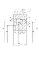
- the angular ball bearing 1 of the present embodiment includes an outer ring 10 having a raceway surface 11 on an inner peripheral surface, an inner ring 20 having a raceway surface 21 on an outer peripheral surface, and raceway surfaces of the outer ring 10 and the inner ring 20. 11 and 21, a plurality of balls 3, and a crown-shaped cage 30 that holds the balls 3 in a freely rolling manner and is a ball guide system.
- the outer peripheral surface of the outer ring 10 is protruded on the back side (load side; left side in FIG. 1) of the raceway surface 11 and the front side of the raceway surface 11 (on the anti-load side). 1 on the right side of the outer ring counter bore 13.
- the outer peripheral surface of the inner ring 20 is an inner ring groove shoulder 22 projecting on the front side (load side; right side in FIG. 1) from the raceway surface 21, and the back side (anti-load side, FIG. 1). And an inner ring counter bore 23 recessed in the middle left side.).
- the contact angle ⁇ of the ball 3 can be set large. More specifically, the contact angle ⁇ can be set to about 45 ° ⁇ ⁇ ⁇ 65 ° by setting the outer diameter D2 and the inner diameter D4 as described above. Considering the variation of the contact angle ⁇ at the time of manufacturing the bearing, it can be set to about 50 ° ⁇ ⁇ ⁇ 60 °. Thus, the contact angle ⁇ can be increased.
- a taper-shaped outer ring chamfering 14 is provided at the rear side end of the outer ring groove shoulder 12 toward the outer side in the radial direction toward the rear side.
- a tapered inner ring chamfer 24 is provided at the front side end of the inner ring groove shoulder 22 and extends radially inward toward the front side.
- the radial widths of the outer ring chamfer 14 and the inner ring chamfer 24 are set to a relatively large value that is larger than half of the radial heights He and Hi of the outer ring groove shoulder 12 and the inner ring groove shoulder 22.
- Such an angular ball bearing 1 can be used in parallel as shown in FIG. Since the angular ball bearing 1 of the present embodiment is provided with the outer ring groove shoulder 12 and the inner ring groove shoulder 22 up to the vicinity of the pitch circle diameter dm of the ball 3, the outer ring chamfer 14 and the inner ring chamfer 24 are not provided. The inner ring 20 of one angular ball bearing 1 and the outer ring 10 of the other angular ball bearing 1 interfere with each other, causing a problem during rotation of the bearing. In addition, when used in oil lubrication, if the outer ring chamfer 14 and the inner ring chamfer 24 are not provided, the oil does not pass between the angular ball bearings 1, and the oil is poorly lubricated.
- outer ring chamfer 14 and the inner ring chamfer 24 it is possible to prevent interference between the inner ring 20 and the outer ring 10 and to improve oil repellency.
- Both the outer ring chamfer 14 and the inner ring chamfer 24 do not necessarily need to be provided, and at least one may be provided.
- the crown type cage 30 is a ball guide type plastic cage made of synthetic resin, and the base resin constituting the crown type cage 30 is a polyamide resin.
- the kind of polyamide resin is not restrict
- glass fiber, carbon fiber, aramid fiber, or the like is added to the base resin as a reinforcing material.
- the crown type cage 30 is manufactured by injection molding or cutting.
- the crown-shaped cage 30 protrudes in the axial direction at a predetermined interval from the substantially annular ring portion 31 (see FIG. 1) arranged coaxially with the inner ring 20 and the outer ring 10 (see FIG. 1).
- a plurality of column portions 32 and a plurality of pocket portions 33 formed between adjacent column portions 32 are provided.
- the radial heights He and Hi of the outer ring groove shoulder portion 12 and the inner ring groove shoulder portion 22 are increased in order to realize a high load capability of the axial load.
- the bearing internal space is reduced. Accordingly, since the crown type cage 30 disposed in such a bearing inner space has a one-side ring structure, the ring portion 31 is disposed between the outer ring counter bore 13 and the inner ring groove shoulder portion 22, and the outer ring 10 and the inner ring
- the column portion 32 is disposed between the 20 raceway surfaces 11 and 21, and the ring portion 31 is connected to the radially outer end of the column portion 32.
- the spherical center position of the pocket portion 33 is radially inward (one radial direction side) from the radial intermediate position m between the outermost diameter portion m1 and the innermost diameter portion m2 of the ring portion 31. ).
- the spherical center position of the pocket portion 33 is a position that coincides with the center of the radius of curvature of the pocket portion 33.
- the outermost diameter part m1 of the ring part 31 is the radial direction outer side surface 31b
- the outermost diameter part m2 is the radial direction inner side face 31a.
- the spherical center position of the pocket portion 33 is shifted radially inward from the innermost diameter portion m ⁇ b> 2 of the ring portion 31.
- the side surface seen from the circumferential direction of the column part 32 which forms the pocket part 33 is the radial inner side surface (radial one side surface) 31a and the radial outer side surface (radial other side surface) of the ring part 31. )
- a part of the arc 33a connecting to 31b is cut away.
- the center of the arc 33a is indicated by P, and the radius is indicated by r.
- the side surface viewed from the circumferential direction of the column part 32 is a first straight formed so that the radially inner end (radial one side end) of the arc 33a is notched and extends in the axial direction.
- the shape part 33b is included.
- the 1st straight shape part 33b is arrange
- the first straight shape portion 33b overlaps the center Oi of the ball 3 (the spherical center of the pocket portion 33) in the axial direction.
- the side surface viewed from the circumferential direction of the column part 32 includes an end part of the arc 33a on the front side of the first straight shape part 33b and an end part on the back side of the radial inner side face 31a of the ring part 31. It includes a second straight shape portion 33c formed by cutting a portion to be tied. Therefore, the 2nd straight shape part 33c is made into the linear shape which goes to a radial direction outer side as it goes to the front side (ring part 31 side).
- the side surface of the pillar portion 32 viewed from the circumferential direction has a third straight shape portion 33g formed such that the radially outer end portion (radial other side end portion) of the arc 33a is notched and extends in the axial direction. including.
- the third straight shape portion 33g is formed on the same plane as the radial outer surface 31b of the ring portion 31, and is connected to the radial outer surface 31b without a step.
- the side surface of the pillar portion 32 viewed from the circumferential direction has a shape in which the third straight shape portion 33g, the arc 33a, the first straight shape portion 33b, and the second straight shape portion 33c are connected. It has become.
- both side surfaces in the circumferential direction of the column portion 32 and side surfaces on the back side (column portion 32 side) of the ring portion 31 forming the pocket portion 33 are spherical shapes similar to the balls 3.
- the tip of the column part 32 is provided with a notch 34 in the middle in the circumferential direction, and is divided into two parts.
- a pair of claw portions 36 are formed at the tip of the column portion 32 on both sides in the circumferential direction of the notch portion 34.
- the cutout portion 34 of the present embodiment has a sharp shape with a substantially V-shaped cross section, but is not limited to this shape, and is, for example, a fixed plane (for example, a plane of 0.1 mm or more).
- the ratio of the reinforcing material added to the synthetic resin of the crown-shaped cage 30 material is preferably 5 to 30 weight percent. If the proportion of the reinforcing material in the synthetic resin component exceeds 30% by weight, the flexibility of the crown-type cage 30 is reduced, and therefore when the mold is forcibly removed from the pocket portion 33 when the crown-type cage 30 is molded. Or the corner
- the thermal expansion of the crown-shaped cage 30 depends on the linear expansion coefficient of the resin material that is the base material, the heat of the crown-shaped cage 30 during the rotation of the bearing when the proportion of the reinforcing material is less than 5 weight percent.
- the expansion becomes larger with respect to the expansion of the pitch circle diameter dm of the ball 3, and the ball 3 and the pocket portion 33 of the crown type retainer 30 stick together, resulting in problems such as seizure. Therefore, the above-mentioned problem can be prevented by setting the ratio of the reinforcing material in the synthetic resin component in the range of 5 to 30% by weight.
- resins such as polyamide, polyether ether ketone, polyphenylene sulfide, and polyimide are applied. Glass fiber, carbon fiber, aramid fiber, or the like is used as the synthetic resin reinforcing material.
- the angular ball bearing 1 of the present embodiment is set so that the number of balls 3 (the number of balls Z) is increased in order to increase the axial load capacity.
- FIG. 8 shows two balls 3 arranged on a pitch circle having a diameter dm.
- the diameter of these balls 3 is Dw
- the centers of these balls 3 are A and B
- the intersections of the line segment AB and the surface of the ball 3 are C and D
- the midpoint of the line segment AB is E
- the pitch The center of the circle is O.
- the distance between the centers of the balls 3 that is the distance between the centers A and B of the adjacent balls 3 is T
- the distance between the balls that is the distance of the adjacent balls 3 is the distance of the line segment CD.
- Is L and the angle between line segment EO and line segment BO (angle between line segment EO and line segment AO) is ⁇ .
- the distance between the line segment AO and the line segment BO is (dm / 2)
- the ball center distance T is (dm ⁇ sin ⁇ )
- the ball distance L is (T ⁇ Dw)
- the angle ⁇ is (180 ° / Z).
- the pitch 3 pitch circumference length ⁇ dm is 2.5 ⁇ 10 ⁇ 3 ⁇ L / ⁇ dm ⁇ 13 ⁇ 10
- the design is such that the relationship of ⁇ 3 is established. If L / ⁇ dm is smaller than 2.5 ⁇ 10 ⁇ 3 , the circumferential thickness of the column portion 32 of the crown type cage 30 becomes too thin, and a hole is formed during molding or cutting. In particular, if the synthetic resin that is the material of the crown-shaped cage 30 contains a large amount of reinforcing material, the fluidity of the synthetic resin deteriorates during molding, and holes are easily opened. On the other hand, if L / ⁇ dm is larger than 13 ⁇ 10 ⁇ 3 , the number of balls Z is reduced, and the axial load carrying capacity and rigidity of the bearing are lowered.
- the angular ball bearing 1 is designed so as to satisfy 2.5 ⁇ 10 ⁇ 3 ⁇ L / ⁇ dm ⁇ 13 ⁇ 10 ⁇ 3 , that is, the number of balls Z is relatively large.
- the circumferential thickness of the column 32 of the vessel 30 cannot be increased relative to the standard bearing.
- the circumferential width N of the claw portion 36 decreases as the circumferential thickness M of the pillar portion 32 decreases. Therefore, when the crown type cage 30 is manufactured by the axial draw type injection molding, in order to remove the die member forming the pocket portion 33 in the axial direction without damaging the column portion 32 in the die drawing process.
- These minimum circumferential thickness M and circumferential width N need to be set appropriately. More specifically, a description will be given with reference to FIG.
- the mold moves relatively in the axial direction of the crown type cage 30.
- the spherical mold 40 that forms the internal shape of the pocket portion 33 has a pair of claw portions 36 formed at the tip of the column portion 32 and facing each other in the circumferential direction (in the direction of arrow A in the figure) toward the notch portion 34. It is extracted in the axial direction (the direction of arrow B in the figure) while being elastically deformed.
- Y is a value referred to as a so-called excessive removal amount.
- the above-mentioned problem does not occur in the claw portion if the forcibly removed amount is an appropriate value within the above range.
- the thickness of the column portion 32 is thin due to the bearing internal design specifications specific to the application. Therefore, when the mold is extracted, the claw portion 36 is elastically deformed by the spherical mold 40, and the pair of claw portions 36 facing each other at the tip of the column portion 32 come into contact with each other so as to be crushed. When the amount of crushing exceeds a certain value, the elastic deformation is shifted to plastic deformation, and the claw portion 36 is broken or cracked.
- the relationship between the circumferential minimum thickness M of the pillar portion 32, the circumferential width N of the claw portion 36, and the ball pitch circumferential length ⁇ dm is ⁇ 3.5 ⁇ 10 ⁇ 3 ⁇ (M ⁇ 2N) / ⁇ dm ⁇ 0.
- the circumferential minimum thickness M of the pillar portion 32 is the minimum value of the circumferential thickness of the pillar portion 32 other than the position where the claw portion 36 or the notch portion 34 is formed. Means.
- the circumferential width N of the claw portion 36 is desirably 0.2 mm or more.
- the configuration of the crown-type cage 30 of the present embodiment is such that the resin fluidity at the time of injection molding is likely to deteriorate in the resin material to which the reinforcing material as described above is added, and the molding die is forcibly removed. The effect is particularly exerted under difficult conditions.
- the cage 130 is substantially circular.
- a crown-shaped cage having an annular ring portion 131, a plurality of column portions 132 protruding in the axial direction from the ring portion 131 at a predetermined interval, and a plurality of pocket portions 133 formed between adjacent column portions 132 It is said that.
- the use application is for a motor or the like, and the angular ball for ball screw support of the present embodiment is limited due to the relatively light load and restrictions on the assembly of the deep groove ball bearing 100.
- the number of balls is as small as about 1/2 to 1/3. Therefore, the pitch in the circumferential direction of the pocket portion 133 of the cage 130 is wide, and the pair of corner portions 135 of the column portion 132 are separated from each other as compared with the pair of corner portions 35 of the column portion 32 of the present embodiment. Yes. Therefore, the concave portion 136 can be provided between the pair of corner portions 135 for the purpose of easily deforming the tip portion of the column portion 132 when the mold is forcibly removed.
- the bottom surface 137 of the recess 136 can be a plane extending in the circumferential direction. Then, a pin for punching is provided on the bottom surface 137 of the recess 136, and the pin is pushed out in the axial direction with respect to the die of the pocket portion 133, so that it is possible to release the die without forcing.
- the cage 130 is less likely to be damaged when the mold is forcibly removed, and the problem of the present invention has not been recognized.
- the crown type retainer 30 As shown in FIGS. 10 to 13, the crown type retainer 30 according to the second embodiment includes first, second, and third straight shape portions 33b, 33c, and 33g as in the first embodiment (see FIG. 7). Is not provided, and the side surface of the column portion 32 forming the pocket portion 33 viewed from the circumferential direction is a circle having an arbitrary radius r.
- the spherical center position of the pocket portion 33 is determined from the radial intermediate position m between the outermost diameter portion m1 and the innermost diameter portion m2 of the ring portion 31 as in the first and second embodiments shown in FIGS.
- the configuration is not limited to the configuration shifted radially inward. That is, as in the third embodiment shown in FIGS. 14 to 16 and the fourth embodiment shown in FIGS. 17 and 18, the spherical center position of the pocket portion 33 is the same as the outermost diameter portion m1 of the ring portion 31.
- a structure shifted from the radially intermediate position m with respect to the inner diameter portion m2 to the radially outer side may be used.
- the ring portion 31 is disposed between the outer ring groove shoulder 12 and the inner ring counter bore 23
- the column portion 32 is disposed between the raceway surfaces 11 and 21 of the outer ring 10 and the inner ring 20, and the inner side in the radial direction of the column portion 32. It is good also as a structure where the ring part 31 connects to an edge part.
- the spherical center position of the pocket portion 33 is shifted radially outward from the outermost diameter portion m1 (radially outer surface 31b) of the ring portion 31.
- the notch 34 is provided in the middle in the circumferential direction at the tip of the column 32 and is divided into two parts, the pocket 33 is formed when the retainer 30 is manufactured by injection molding. It is possible to prevent the corner portion 35 on the pocket portion 33 side of the column portion 32 from being damaged by forcibly removing the mold parts forming the.
- the side surface viewed from the circumferential direction of the column portion 32 that forms the pocket portion 33 is the radial outer surface (one radial side surface) 31 b of the ring portion 31 and the radial direction.
- a part of the arc 33a connecting the inner side surface (the other side surface in the radial direction) 31a is cut away.
- the center of the arc 33a is indicated by P, and the radius is indicated by r.
- the side surface viewed from the circumferential direction of the column portion 32 is a first straight formed so that the radially outer end portion (radial one side end portion) of the arc 33a is notched and extends in the axial direction.
- the shape part 33b is included.
- the first straight shape portion 33b is arranged on the front side (the anti-load side, left side in FIG. 16) from the center P of the circle.
- the first straight shape portion 33b overlaps the center Oi of the ball 3 (the spherical center of the pocket portion 33) in the axial direction.
- the side surface seen from the circumferential direction of the column part 32 is the end of the arc 33a on the back side (load side; right side in FIG. 16) of the first straight shape part 33b and the radially outer side surface of the ring part 31. It includes a second straight shape portion 33c formed by cutting out a portion connecting the front end portion of 31b. Therefore, the 2nd straight shape part 33c is made into the linear shape which goes to a radial inside as it goes to the back side (ring part 31 side).
- the side surface of the pillar portion 32 viewed from the circumferential direction has a third straight shape portion 33g formed such that the radially inner end portion (radial other side end portion) of the arc 33a is cut out and extends in the axial direction. including.
- the third straight shape portion 33g is formed on the same plane as the radial inner side surface 31a of the ring portion 31, and is connected to the radial inner side surface 31a without a step.
- the side surface of the pillar portion 32 viewed from the circumferential direction has a shape in which the third straight shape portion 33g, the arc 33a, the first straight shape portion 33b, and the second straight shape portion 33c are connected. It has become.
- the side surface of the pillar portion 32 forming the pocket portion 33 viewed from the circumferential direction is a circular shape having an arbitrary radius r.
- 2.5 ⁇ 10 ⁇ 3 ⁇ L / ⁇ dm ⁇ 13 ⁇ 10 ⁇ 3 and ⁇ 3.5 ⁇ 10 ⁇ 3 ⁇ (M ⁇ 2N ) / ⁇ dm ⁇ 0 can be set to satisfy the same effects as those of the above-described embodiment.
- the spherical center position of the pocket portion 33 and the radial intermediate position m between the outermost diameter portion m1 and the innermost diameter portion m2 of the ring portion 31 may coincide with each other in the radial direction.
- the inner peripheral surface of the outer ring 10 has an outer ring groove shoulder 12 projecting on the back side (load side; right side in FIG. 19) of the raceway surface 11 and the front side of the raceway surface 11 ( And an outer ring counter bore 13 which is recessed in the counter-load side (left side in FIG. 19).
- an inner ring groove shoulder portion 22 is projected on the front side and the back side of the raceway surface 21.
- the ring part 31 is arrange
- the pillar part 32 is arrange
- the ring portion 31 is connected to the central portion in the radial direction.
- the side surface seen from the circumferential direction of the column part 32 which forms the pocket part 33 is circular shape of arbitrary radii r.
- 2.5 ⁇ 10 ⁇ 3 ⁇ L / ⁇ dm ⁇ 13 ⁇ 10 ⁇ 3 and ⁇ 3.5 ⁇ 10 ⁇ 3 ⁇ (M ⁇ 2N ) / ⁇ dm ⁇ 0 can be set to satisfy the same effects as those of the above-described embodiment.
- the spherical center position (ball center Oi) of the pocket portion 33 is offset in the axial direction (front side) from the axial center of the angular ball bearing 1. That is, the axial distance from the end surface 4 of the angular ball bearing 1 on the back side (right side in FIG. 19) where the ring portion 31 is arranged to the spherical center position of the pocket portion 33 is X, and the front side (left side in FIG. 19). ), The axial distance from the end surface 5 of the angular ball bearing 1 to the spherical center position of the pocket portion 33 is set such that X> Y.
- the axial direction space between the end surface 4 of the angular ball bearing 1 on the back side and the surface of the ball 3 can be widened.
- the axial direction dimension of the ring part 31 can be enlarged and the annular
- the spherical center position (ball center Oi) of the pocket portion 33 and the axial center of the angular ball bearing 1 may coincide as shown in FIG. .
- the spherical center position of the pocket portion 33 and the radial intermediate position m between the outermost diameter portion m1 and the innermost diameter portion m2 of the ring portion 31 may coincide with each other in the radial direction.
- the inner peripheral surface of the outer ring 10 has an outer ring groove shoulder 12 that protrudes on the inner side (load side) in the axial direction from the raceway surface 11, and an outer side in the axial direction (on the opposite load side) from the raceway surface 11.
- the outer peripheral surface of the inner ring 20 includes an inner ring groove shoulder portion 22 that protrudes inward in the axial direction from the raceway surface 21, and an inner ring seal groove 25 that is recessed inwardly in the axial direction from the raceway surface 21.
- the ring part 31 is arrange
- the ring portion 31 is connected to the central portion in the radial direction.
- the side surface seen from the circumferential direction of the column part 32 which forms the pocket part 33 is circular shape of arbitrary radii r.
- a seal member 50 is fixed in the outer ring seal groove 15.
- the seal member 50 is opposed to the inner ring seal groove 25 with a slight gap, and prevents foreign matter from entering the bearing.
- the seal member 50 is not limited to a non-contact seal but may be a contact seal.
- the angular ball bearing 1 can be made compact by disposing the ring portion 31 on the inner side in the axial direction and the seal member 50 on the outer side in the axial direction with respect to the pocket portion 33.
- Such an angular ball bearing 1 can be used in a rear combination as shown in FIG.
- 2.5 ⁇ 10 ⁇ 3 ⁇ L / ⁇ dm ⁇ 13 ⁇ 10 ⁇ 3 and ⁇ 3.5 ⁇ 10 ⁇ 3 ⁇ (M ⁇ 2N ) / ⁇ dm ⁇ 0 can be set to satisfy the same effects as those of the above-described embodiment.
- the spherical center position (ball center Oi) of the pocket portion 33 is offset from the axial center of the angular ball bearing 1 to the axially outer side (front side). That is, the relationship between the axial distances X and Y is set such that X> Y. Thereby, the axial direction space between the end surface 4 of the angular ball bearing 1 and the surface of the ball 3 on the back side (in the axial direction in FIG. 21) can be widened. Thereby, the axial direction dimension of the ring part 31 can be enlarged and the annular
- the spherical center position (ball center Oi) of the pocket portion 33 and the axial direction center of the angular ball bearing 1 may coincide with each other.
- Examples 1 and 2 Next, by changing (M ⁇ 2N) / ⁇ dm as shown in Table 1 and manufacturing the crown type cage 30 by the axial draw type injection molding, the damaged state of the pair of claws 36 of the column 32 The test was conducted. In Examples 1 and 2 and Comparative Example 1, parameters other than (M ⁇ 2N) / ⁇ dm were the same as shown below.
- bearing inner diameter ⁇ 45 mm
- bearing outer diameter ⁇ 100 mm
- ball pitch circle diameter dm ⁇ 75 mm
- ball diameter Dw 10.319 mm
- number of balls Z 21
- contact angle ⁇ 60 °
- crown type cage material polyamide resin ( 20 wt.% Glass fiber reinforcing material), L / ⁇ dm: 3.6 ⁇ 10 ⁇ 3
- the bearing inner diameter is ⁇ 30 mm
- the bearing outer diameter is ⁇ 62 mm
- L / ⁇ dm 5.0 ⁇ 10 ⁇ 3
- (M ⁇ 2N) / ⁇ dm ⁇ 1.
- the bearing inner diameter is ⁇ 50 mm
- the bearing outer diameter is ⁇ 100 mm
- L / ⁇ dm 3.5 ⁇ 10 ⁇ 3
- (M ⁇ 2N) / ⁇ dm It was set to ⁇ 0.7 ⁇ 10 ⁇ 3 .
- the bearing inner diameter is ⁇ 20 mm
- the bearing outer diameter is ⁇ 47 mm
- L / ⁇ dm 11.4 ⁇ 10 ⁇ 3
- (M ⁇ 2N) / ⁇ dm ⁇ 3.
Landscapes
- Engineering & Computer Science (AREA)
- General Engineering & Computer Science (AREA)
- Mechanical Engineering (AREA)
- Rolling Contact Bearings (AREA)
Abstract
Selon l'invention, une encoche (34) est présente dans le centre circonférentiel de l'extrémité de pointe d'une section colonne (32), une paire de cliquets (36) étant formée dans les deux côtés circonférentiels. La relation entre la distance L entre des billes adjacentes (3) et la longueur de circonférence primitive principale πdm, qui est le produit du diamètre de cercle primitif principal dm et de la constante du cercle π, respecte l'équation 2,5 × 10⁻³ ≤ L/πdm ≤ 13 × 10-3. La relation entre l'épaisseur minimale circonférentielle M de la section colonne (32), la largeur circonférentielle N des cliquets (36), et la longueur de circonférence primitive principale πdm, respecte l'équation à -3,5 × 10⁻³ ≤ (M-2N)/ πdm < 0.
Priority Applications (2)
| Application Number | Priority Date | Filing Date | Title |
|---|---|---|---|
| KR1020167036852A KR20170015372A (ko) | 2014-07-02 | 2015-06-26 | 관형 유지기 및 앵귤러 볼 베어링 |
| CN201580036047.6A CN106662152A (zh) | 2014-07-02 | 2015-06-26 | 冠型保持架和角接触球轴承 |
Applications Claiming Priority (4)
| Application Number | Priority Date | Filing Date | Title |
|---|---|---|---|
| JP2014136858 | 2014-07-02 | ||
| JP2014-136858 | 2014-07-02 | ||
| JP2015-117336 | 2015-06-10 | ||
| JP2015117336A JP2016027279A (ja) | 2014-07-02 | 2015-06-10 | 冠型保持器及びアンギュラ玉軸受 |
Publications (1)
| Publication Number | Publication Date |
|---|---|
| WO2016002681A1 true WO2016002681A1 (fr) | 2016-01-07 |
Family
ID=55019217
Family Applications (1)
| Application Number | Title | Priority Date | Filing Date |
|---|---|---|---|
| PCT/JP2015/068590 WO2016002681A1 (fr) | 2014-07-02 | 2015-06-26 | Cage couronne et roulement à billes à contact oblique |
Country Status (5)
| Country | Link |
|---|---|
| JP (1) | JP2016027279A (fr) |
| KR (1) | KR20170015372A (fr) |
| CN (1) | CN106662152A (fr) |
| TW (1) | TWI568943B (fr) |
| WO (1) | WO2016002681A1 (fr) |
Families Citing this family (4)
| Publication number | Priority date | Publication date | Assignee | Title |
|---|---|---|---|---|
| JP6897802B2 (ja) * | 2018-01-26 | 2021-07-07 | 日本精工株式会社 | アンギュラ玉軸受 |
| JP7543660B2 (ja) * | 2020-03-03 | 2024-09-03 | 日本精工株式会社 | 玉軸受用冠型保持器、及び玉軸受 |
| CN114321184A (zh) * | 2020-10-10 | 2022-04-12 | 斯凯孚(中国)有限公司 | 轴承保持架及其应用 |
| CN113294441A (zh) * | 2021-05-10 | 2021-08-24 | 洛阳轴承研究所有限公司 | 一种注塑保持架及使用该注塑保持架的轴承 |
Citations (4)
| Publication number | Priority date | Publication date | Assignee | Title |
|---|---|---|---|---|
| JPS5557517U (fr) * | 1978-10-16 | 1980-04-18 | ||
| JPH09280254A (ja) * | 1995-12-08 | 1997-10-28 | Skf Ind Trading Dev Co Bv | ころがり軸受のための保持器 |
| JP2006017180A (ja) * | 2004-06-30 | 2006-01-19 | Koyo Seiko Co Ltd | 合成樹脂製の冠形保持器 |
| JP2007333187A (ja) * | 2006-06-19 | 2007-12-27 | Ntn Corp | 玉軸受用冠形樹脂保持器およびこれを組み込んだ玉軸受 |
Family Cites Families (12)
| Publication number | Priority date | Publication date | Assignee | Title |
|---|---|---|---|---|
| SE7810946L (sv) * | 1978-10-20 | 1980-04-21 | Draco Ab | Metod att behandla kronisk obstruktiv luftvegssjukdom |
| JPH0349417A (ja) | 1989-07-18 | 1991-03-04 | Nec Corp | 半導体集積回路 |
| US5575570A (en) * | 1994-07-08 | 1996-11-19 | Nsk Ltd. | Cage for rolling bearing |
| US5941704A (en) * | 1995-02-20 | 1999-08-24 | Koyo Seiko Co., Ltd. | Crown cage for ball bearing and dental hand piece including the same |
| JP2000104742A (ja) | 1998-09-29 | 2000-04-11 | Ntn Corp | ボールねじ支持用転がり軸受 |
| JP2002295479A (ja) * | 2001-03-29 | 2002-10-09 | Koyo Seiko Co Ltd | 軸受用保持器 |
| JP4055938B2 (ja) * | 2002-04-18 | 2008-03-05 | ミネベア株式会社 | ラジアルボールベアリングのリテーナ |
| EP1367277B1 (fr) * | 2002-05-30 | 2008-06-25 | Minebea Co., Ltd. | Système de maintien avec des poches présentants une symétrie de révolution |
| JP2005061508A (ja) | 2003-08-11 | 2005-03-10 | Nsk Ltd | アンギュラ玉軸受 |
| JP4863077B2 (ja) * | 2004-12-07 | 2012-01-25 | 株式会社ジェイテクト | 玉軸受用保持器とそれを用いた玉軸受 |
| DE102007061589B4 (de) * | 2007-01-29 | 2017-06-22 | Nsk Ltd. | Kugellager und Halterungskonstruktion |
| JP2014066346A (ja) * | 2012-09-27 | 2014-04-17 | Nsk Ltd | 玉軸受保持器及び玉軸受 |
-
2015
- 2015-06-10 JP JP2015117336A patent/JP2016027279A/ja active Pending
- 2015-06-26 CN CN201580036047.6A patent/CN106662152A/zh active Pending
- 2015-06-26 WO PCT/JP2015/068590 patent/WO2016002681A1/fr active Application Filing
- 2015-06-26 KR KR1020167036852A patent/KR20170015372A/ko not_active Application Discontinuation
- 2015-07-02 TW TW104121539A patent/TWI568943B/zh not_active IP Right Cessation
Patent Citations (4)
| Publication number | Priority date | Publication date | Assignee | Title |
|---|---|---|---|---|
| JPS5557517U (fr) * | 1978-10-16 | 1980-04-18 | ||
| JPH09280254A (ja) * | 1995-12-08 | 1997-10-28 | Skf Ind Trading Dev Co Bv | ころがり軸受のための保持器 |
| JP2006017180A (ja) * | 2004-06-30 | 2006-01-19 | Koyo Seiko Co Ltd | 合成樹脂製の冠形保持器 |
| JP2007333187A (ja) * | 2006-06-19 | 2007-12-27 | Ntn Corp | 玉軸受用冠形樹脂保持器およびこれを組み込んだ玉軸受 |
Also Published As
| Publication number | Publication date |
|---|---|
| CN106662152A (zh) | 2017-05-10 |
| TWI568943B (zh) | 2017-02-01 |
| KR20170015372A (ko) | 2017-02-08 |
| TW201608143A (zh) | 2016-03-01 |
| JP2016027279A (ja) | 2016-02-18 |
Similar Documents
| Publication | Publication Date | Title |
|---|---|---|
| JP6728585B2 (ja) | アンギュラ玉軸受 | |
| JP6569663B2 (ja) | アンギュラ玉軸受 | |
| WO2016002681A1 (fr) | Cage couronne et roulement à billes à contact oblique | |
| KR102013084B1 (ko) | 원추 롤러 베어링 및 원추 롤러 베어링의 제조 방법 | |
| JP2019074214A (ja) | アンギュラ玉軸受及びその製造方法 | |
| KR102018966B1 (ko) | 구름 베어링용 유지기, 및 구름 베어링, 그리고 구름 베어링용 유지기의 제조 방법 | |
| JP6686483B2 (ja) | 転がり軸受用保持器、及び転がり軸受、並びに転がり軸受用保持器の製造方法 | |
| JP6376212B2 (ja) | アンギュラ玉軸受 | |
| JP6529209B2 (ja) | アンギュラ玉軸受 | |
| JP6686482B2 (ja) | 転がり軸受用保持器、及び転がり軸受、並びに転がり軸受用保持器の製造方法 | |
| JP6556454B2 (ja) | 玉軸受用保持器 | |
| WO2018034246A1 (fr) | Roulement à billes, et dispositif de broche de machine-outil | |
| JP2007120766A (ja) | 転がり軸受用保持器 | |
| JP4366580B2 (ja) | 玉軸受用保持器 | |
| EP3492760B1 (fr) | Roulement à billes | |
| JP2005127493A (ja) | 円筒ころ軸受 | |
| JP2006266504A (ja) | 転がり軸受用保持器 |
Legal Events
| Date | Code | Title | Description |
|---|---|---|---|
| 121 | Ep: the epo has been informed by wipo that ep was designated in this application |
Ref document number: 15815453 Country of ref document: EP Kind code of ref document: A1 |
|
| ENP | Entry into the national phase |
Ref document number: 20167036852 Country of ref document: KR Kind code of ref document: A |
|
| NENP | Non-entry into the national phase |
Ref country code: DE |
|
| 122 | Ep: pct application non-entry in european phase |
Ref document number: 15815453 Country of ref document: EP Kind code of ref document: A1 |