WO2015198988A1 - 有機エレクトロルミネッセンス素子、有機エレクトロルミネッセンス素子用材料、および電子機器 - Google Patents
有機エレクトロルミネッセンス素子、有機エレクトロルミネッセンス素子用材料、および電子機器 Download PDFInfo
- Publication number
- WO2015198988A1 WO2015198988A1 PCT/JP2015/067747 JP2015067747W WO2015198988A1 WO 2015198988 A1 WO2015198988 A1 WO 2015198988A1 JP 2015067747 W JP2015067747 W JP 2015067747W WO 2015198988 A1 WO2015198988 A1 WO 2015198988A1
- Authority
- WO
- WIPO (PCT)
- Prior art keywords
- group
- substituted
- carbon atoms
- compound
- general formula
- Prior art date
Links
Images
Classifications
-
- H—ELECTRICITY
- H10—SEMICONDUCTOR DEVICES; ELECTRIC SOLID-STATE DEVICES NOT OTHERWISE PROVIDED FOR
- H10K—ORGANIC ELECTRIC SOLID-STATE DEVICES
- H10K85/00—Organic materials used in the body or electrodes of devices covered by this subclass
- H10K85/60—Organic compounds having low molecular weight
- H10K85/649—Aromatic compounds comprising a hetero atom
- H10K85/657—Polycyclic condensed heteroaromatic hydrocarbons
-
- C—CHEMISTRY; METALLURGY
- C09—DYES; PAINTS; POLISHES; NATURAL RESINS; ADHESIVES; COMPOSITIONS NOT OTHERWISE PROVIDED FOR; APPLICATIONS OF MATERIALS NOT OTHERWISE PROVIDED FOR
- C09K—MATERIALS FOR MISCELLANEOUS APPLICATIONS, NOT PROVIDED FOR ELSEWHERE
- C09K11/00—Luminescent, e.g. electroluminescent, chemiluminescent materials
- C09K11/06—Luminescent, e.g. electroluminescent, chemiluminescent materials containing organic luminescent materials
-
- H—ELECTRICITY
- H10—SEMICONDUCTOR DEVICES; ELECTRIC SOLID-STATE DEVICES NOT OTHERWISE PROVIDED FOR
- H10K—ORGANIC ELECTRIC SOLID-STATE DEVICES
- H10K85/00—Organic materials used in the body or electrodes of devices covered by this subclass
- H10K85/60—Organic compounds having low molecular weight
- H10K85/615—Polycyclic condensed aromatic hydrocarbons, e.g. anthracene
- H10K85/622—Polycyclic condensed aromatic hydrocarbons, e.g. anthracene containing four rings, e.g. pyrene
-
- H—ELECTRICITY
- H10—SEMICONDUCTOR DEVICES; ELECTRIC SOLID-STATE DEVICES NOT OTHERWISE PROVIDED FOR
- H10K—ORGANIC ELECTRIC SOLID-STATE DEVICES
- H10K85/00—Organic materials used in the body or electrodes of devices covered by this subclass
- H10K85/60—Organic compounds having low molecular weight
- H10K85/615—Polycyclic condensed aromatic hydrocarbons, e.g. anthracene
- H10K85/626—Polycyclic condensed aromatic hydrocarbons, e.g. anthracene containing more than one polycyclic condensed aromatic rings, e.g. bis-anthracene
-
- H—ELECTRICITY
- H10—SEMICONDUCTOR DEVICES; ELECTRIC SOLID-STATE DEVICES NOT OTHERWISE PROVIDED FOR
- H10K—ORGANIC ELECTRIC SOLID-STATE DEVICES
- H10K85/00—Organic materials used in the body or electrodes of devices covered by this subclass
- H10K85/60—Organic compounds having low molecular weight
- H10K85/631—Amine compounds having at least two aryl rest on at least one amine-nitrogen atom, e.g. triphenylamine
- H10K85/633—Amine compounds having at least two aryl rest on at least one amine-nitrogen atom, e.g. triphenylamine comprising polycyclic condensed aromatic hydrocarbons as substituents on the nitrogen atom
-
- H—ELECTRICITY
- H10—SEMICONDUCTOR DEVICES; ELECTRIC SOLID-STATE DEVICES NOT OTHERWISE PROVIDED FOR
- H10K—ORGANIC ELECTRIC SOLID-STATE DEVICES
- H10K85/00—Organic materials used in the body or electrodes of devices covered by this subclass
- H10K85/60—Organic compounds having low molecular weight
- H10K85/649—Aromatic compounds comprising a hetero atom
- H10K85/654—Aromatic compounds comprising a hetero atom comprising only nitrogen as heteroatom
-
- H—ELECTRICITY
- H10—SEMICONDUCTOR DEVICES; ELECTRIC SOLID-STATE DEVICES NOT OTHERWISE PROVIDED FOR
- H10K—ORGANIC ELECTRIC SOLID-STATE DEVICES
- H10K85/00—Organic materials used in the body or electrodes of devices covered by this subclass
- H10K85/60—Organic compounds having low molecular weight
- H10K85/649—Aromatic compounds comprising a hetero atom
- H10K85/657—Polycyclic condensed heteroaromatic hydrocarbons
- H10K85/6572—Polycyclic condensed heteroaromatic hydrocarbons comprising only nitrogen in the heteroaromatic polycondensed ring system, e.g. phenanthroline or carbazole
-
- H—ELECTRICITY
- H10—SEMICONDUCTOR DEVICES; ELECTRIC SOLID-STATE DEVICES NOT OTHERWISE PROVIDED FOR
- H10K—ORGANIC ELECTRIC SOLID-STATE DEVICES
- H10K85/00—Organic materials used in the body or electrodes of devices covered by this subclass
- H10K85/60—Organic compounds having low molecular weight
- H10K85/649—Aromatic compounds comprising a hetero atom
- H10K85/657—Polycyclic condensed heteroaromatic hydrocarbons
- H10K85/6574—Polycyclic condensed heteroaromatic hydrocarbons comprising only oxygen in the heteroaromatic polycondensed ring system, e.g. cumarine dyes
-
- C—CHEMISTRY; METALLURGY
- C09—DYES; PAINTS; POLISHES; NATURAL RESINS; ADHESIVES; COMPOSITIONS NOT OTHERWISE PROVIDED FOR; APPLICATIONS OF MATERIALS NOT OTHERWISE PROVIDED FOR
- C09K—MATERIALS FOR MISCELLANEOUS APPLICATIONS, NOT PROVIDED FOR ELSEWHERE
- C09K2211/00—Chemical nature of organic luminescent or tenebrescent compounds
- C09K2211/10—Non-macromolecular compounds
- C09K2211/1003—Carbocyclic compounds
- C09K2211/1007—Non-condensed systems
-
- C—CHEMISTRY; METALLURGY
- C09—DYES; PAINTS; POLISHES; NATURAL RESINS; ADHESIVES; COMPOSITIONS NOT OTHERWISE PROVIDED FOR; APPLICATIONS OF MATERIALS NOT OTHERWISE PROVIDED FOR
- C09K—MATERIALS FOR MISCELLANEOUS APPLICATIONS, NOT PROVIDED FOR ELSEWHERE
- C09K2211/00—Chemical nature of organic luminescent or tenebrescent compounds
- C09K2211/10—Non-macromolecular compounds
- C09K2211/1003—Carbocyclic compounds
- C09K2211/1011—Condensed systems
-
- C—CHEMISTRY; METALLURGY
- C09—DYES; PAINTS; POLISHES; NATURAL RESINS; ADHESIVES; COMPOSITIONS NOT OTHERWISE PROVIDED FOR; APPLICATIONS OF MATERIALS NOT OTHERWISE PROVIDED FOR
- C09K—MATERIALS FOR MISCELLANEOUS APPLICATIONS, NOT PROVIDED FOR ELSEWHERE
- C09K2211/00—Chemical nature of organic luminescent or tenebrescent compounds
- C09K2211/10—Non-macromolecular compounds
- C09K2211/1003—Carbocyclic compounds
- C09K2211/1014—Carbocyclic compounds bridged by heteroatoms, e.g. N, P, Si or B
-
- C—CHEMISTRY; METALLURGY
- C09—DYES; PAINTS; POLISHES; NATURAL RESINS; ADHESIVES; COMPOSITIONS NOT OTHERWISE PROVIDED FOR; APPLICATIONS OF MATERIALS NOT OTHERWISE PROVIDED FOR
- C09K—MATERIALS FOR MISCELLANEOUS APPLICATIONS, NOT PROVIDED FOR ELSEWHERE
- C09K2211/00—Chemical nature of organic luminescent or tenebrescent compounds
- C09K2211/10—Non-macromolecular compounds
- C09K2211/1018—Heterocyclic compounds
- C09K2211/1025—Heterocyclic compounds characterised by ligands
- C09K2211/1059—Heterocyclic compounds characterised by ligands containing three nitrogen atoms as heteroatoms
-
- C—CHEMISTRY; METALLURGY
- C09—DYES; PAINTS; POLISHES; NATURAL RESINS; ADHESIVES; COMPOSITIONS NOT OTHERWISE PROVIDED FOR; APPLICATIONS OF MATERIALS NOT OTHERWISE PROVIDED FOR
- C09K—MATERIALS FOR MISCELLANEOUS APPLICATIONS, NOT PROVIDED FOR ELSEWHERE
- C09K2211/00—Chemical nature of organic luminescent or tenebrescent compounds
- C09K2211/10—Non-macromolecular compounds
- C09K2211/1018—Heterocyclic compounds
- C09K2211/1025—Heterocyclic compounds characterised by ligands
- C09K2211/1088—Heterocyclic compounds characterised by ligands containing oxygen as the only heteroatom
-
- H—ELECTRICITY
- H10—SEMICONDUCTOR DEVICES; ELECTRIC SOLID-STATE DEVICES NOT OTHERWISE PROVIDED FOR
- H10K—ORGANIC ELECTRIC SOLID-STATE DEVICES
- H10K2101/00—Properties of the organic materials covered by group H10K85/00
- H10K2101/20—Delayed fluorescence emission
-
- H—ELECTRICITY
- H10—SEMICONDUCTOR DEVICES; ELECTRIC SOLID-STATE DEVICES NOT OTHERWISE PROVIDED FOR
- H10K—ORGANIC ELECTRIC SOLID-STATE DEVICES
- H10K2101/00—Properties of the organic materials covered by group H10K85/00
- H10K2101/30—Highest occupied molecular orbital [HOMO], lowest unoccupied molecular orbital [LUMO] or Fermi energy values
-
- H—ELECTRICITY
- H10—SEMICONDUCTOR DEVICES; ELECTRIC SOLID-STATE DEVICES NOT OTHERWISE PROVIDED FOR
- H10K—ORGANIC ELECTRIC SOLID-STATE DEVICES
- H10K2101/00—Properties of the organic materials covered by group H10K85/00
- H10K2101/90—Multiple hosts in the emissive layer
-
- H—ELECTRICITY
- H10—SEMICONDUCTOR DEVICES; ELECTRIC SOLID-STATE DEVICES NOT OTHERWISE PROVIDED FOR
- H10K—ORGANIC ELECTRIC SOLID-STATE DEVICES
- H10K50/00—Organic light-emitting devices
- H10K50/10—OLEDs or polymer light-emitting diodes [PLED]
- H10K50/11—OLEDs or polymer light-emitting diodes [PLED] characterised by the electroluminescent [EL] layers
Definitions
- the present invention relates to an organic electroluminescence element, a material for an organic electroluminescence element, and an electronic device.
- organic electroluminescence element When a voltage is applied to an organic electroluminescence element (hereinafter sometimes referred to as “organic EL element”), holes from the anode and electrons from the cathode are injected into the light emitting layer. Then, in the light emitting layer, the injected holes and electrons are recombined to form excitons. At this time, singlet excitons and triplet excitons are generated at a ratio of 25%: 75% according to the statistical rule of electron spin. Fluorescent organic EL devices that use light emitted from singlet excitons are said to have an internal quantum efficiency of 25%, and are being applied to full-color displays such as mobile phones and televisions. In addition to singlet excitons, triplet excitons are used, and organic EL devices are expected to emit light more efficiently.
- organic EL element organic electroluminescence element
- TADF Thermally Activated Delayed Fluorescence, heat activated delayed fluorescence
- ⁇ ST small energy difference
- ⁇ ST small energy difference
- Patent Document 1 and Non-Patent Document 1 disclose organic EL elements using the TADF mechanism.
- an organic EL element it is necessary to further improve the luminous efficiency.
- the objective of this invention is providing the organic electroluminescent element which can improve luminous efficiency, providing the material for organic electroluminescent elements used for the said organic electroluminescent element, and the said organic electroluminescent element. To provide electronic equipment.
- an anode, a light emitting layer, and a cathode are included, and the light emitting layer includes a first compound, a second compound, and a third compound, and the first compound is Wherein the singlet energy of the second compound is greater than the singlet energy of the first compound, and the third compound is fluorescent.
- An organic electroluminescent device that is a compound is provided.
- Xa is an oxygen atom, a sulfur atom, NR 1 , or CR 3 R 4
- Xb, Xc, Xd, and Xe are each independently a single bond, an oxygen atom, sulfur, An atom, NR 1 , or CR 3 R 4 , provided that at least one of Xa, Xb, Xc, Xd, and Xe is NR 1 , and Xb and Xc do not simultaneously become a single bond;
- Xe are not simultaneously a single bond, R 1 is a hydrogen atom or a substituent, and when R 1 is a substituent, the substituent is a substituted or unsubstituted alkyl group having 1 to 30 carbon atoms.
- Z 1, Z 2, Z 3, and Z 4 Each independently a ring structure selected from the group consisting of a substituted or unsubstituted aromatic hydrocarbon ring having 6 to 30 ring carbon atoms and a substituted or unsubstituted heterocyclic ring having 5 to 30 ring atoms. is there.)
- an electronic apparatus including the organic electroluminescence element according to one embodiment of the present invention described above is provided.
- the first compound represented by the general formula (1) the second compound having a singlet energy larger than the singlet energy of the first compound
- a material for an organic electroluminescence device comprising a fluorescent third compound.
- an organic electroluminescent element capable of improving luminous efficiency
- an organic electroluminescent element material used for the organic electroluminescent element and to the organic electroluminescent element
- An electronic device including the element can be provided.
- the organic EL element according to this embodiment includes an organic layer between a pair of electrodes.
- This organic layer is composed of at least one layer composed of an organic compound.
- the organic layer is formed by laminating a plurality of layers composed of organic compounds.
- the organic layer may further contain an inorganic compound.
- at least one of the organic layers is a light emitting layer. Therefore, the organic layer may be composed of, for example, a single light emitting layer, and may be employed in organic EL elements such as a hole injection layer, a hole transport layer, an electron injection layer, an electron transport layer, and a barrier layer. Layers may be included.
- the following configurations (a) to (e) can be given.
- (A) Anode / light emitting layer / cathode (b) Anode / hole injection / transport layer / light emitting layer / cathode (c) Anode / light emitting layer / electron injection / transport layer / cathode (d) Anode / hole injection / transport Layer / light emitting layer / electron injection / transport layer / cathode (e) anode / hole injection / transport layer / light emitting layer / barrier layer / electron injection / transport layer / cathode
- the configuration of (d) is preferably used. .
- the “light emitting layer” is an organic layer having a light emitting function.
- the “hole injection / transport layer” means “at least one of a hole injection layer and a hole transport layer”.
- the “electron injection / transport layer” means “at least one of an electron injection layer and an electron transport layer”.
- a hole injection layer is provided between the hole transport layer and the anode.
- an organic EL element has an electron injection layer and an electron carrying layer, it is preferable that the electron injection layer is provided between the electron carrying layer and the cathode.
- each of the hole injection layer, the hole transport layer, the electron transport layer, and the electron injection layer may be composed of a single layer or a plurality of layers.
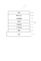
- the organic EL element 1 includes a translucent substrate 2, an anode 3, a cathode 4, and an organic layer 10 disposed between the anode 3 and the cathode 4.
- the organic layer 10 includes a hole injection layer 6, a hole transport layer 7, a light emitting layer 5, an electron transport layer 8, and an electron injection layer 9 that are stacked in this order from the anode 3 side.
- the light emitting layer 5 of the organic EL element 1 includes a first compound, a second compound, and a third compound.
- the light emitting layer 5 may contain a metal complex, in this embodiment, it is preferable not to contain a phosphorescent metal complex, and it is preferable not to contain any metal complexes other than the phosphorescent metal complex.
- the first compound of this embodiment is a compound represented by the following general formula (1).
- the first compound is preferably a delayed fluorescent compound.
- the first compound of this embodiment is not a metal complex.
- Xa is an oxygen atom, a sulfur atom, NR 1 , or CR 3 R 4
- Xb, Xc, Xd, and Xe are each independently a single bond, an oxygen atom, a sulfur atom, NR 1 , or CR 3 R 4
- at least one of Xa, Xb, Xc, Xd, and Xe is NR 1 , Xb and Xc are not simultaneously single-bonded, and Xd and Xe are not simultaneously single-bonded
- R 1 is a hydrogen atom or a substituent, and when R 1 is a substituent, the substituent is A substituted or unsubstituted alkyl group having 1 to 30 carbon atoms, A substituted or unsubstituted cycloalkyl group having 3 to 30 ring carbon atoms, A substituted or unsubstituted aromatic hydrocarbon group having 6 to 30 ring carbon atoms, Selected from the group consisting of
- L 1 is a linking group
- the linking group is a substituted or unsubstituted aromatic hydrocarbon group having 6 to 30 ring carbon atoms, and a substituted or unsubstituted group.
- R 2 to R 4 are each independently a hydrogen atom or a substituent, and when R 2 to R 4 are a substituent, the substituents are each independently A substituted or unsubstituted alkyl group having 1 to 30 carbon atoms, A substituted or unsubstituted cycloalkyl group having 3 to 30 ring carbon atoms, Selected from the group consisting of a substituted or unsubstituted aromatic hydrocarbon group having 6 to 30 ring carbon atoms and a substituted or unsubstituted heterocyclic group having 5 to 30 ring atoms;
- Z 1 , Z 2 , Z 3 , and Z 4 are each independently It is a ring structure selected from the group consisting of a substituted or unsubstituted aromatic hydrocarbon group having
- Xa and the single bond connecting Z 1 and Z 2 are adjacent atoms of the ring structure represented by Z 1 and adjacent to the ring structure represented by Z 2. Bond to each matching atom.
- Xb and Xc are bonded to adjacent atoms of the ring structure represented by Z 2 and adjacent atoms of the ring structure represented by Z 3 , respectively.
- Xd and Xe are bonded to adjacent atoms of the ring structure represented by Z 3 and adjacent atoms of the ring structure represented by Z 4 , respectively.
- Z 1 is a benzene ring
- Z 1 , Xa and a single bond have the following bonding modes (the wavy line portion represents the bonding site with Z 2 ).
- Z 1 , Z 2 , Z 3 , and Z 4 are each independently preferably a substituted or unsubstituted aromatic hydrocarbon ring having 6 to 30 ring carbon atoms. It is more preferably an unsubstituted aromatic hydrocarbon ring having 6 to 20 carbon atoms, and an aromatic hydrocarbon ring selected from the group consisting of a benzene ring, a naphthalene ring, a phenanthrene ring, and a triphenylenylene ring. More preferably, it is particularly preferably a benzene ring.
- two or more of Xa, Xb, Xc, Xd and Xe in the general formula (1) are each independently NR 1 .
- Xa is NR 1 and at least one of Xb, Xc, Xd and Xe is NR 1 .
- an organic compound that realizes thermally activated delayed fluorescence a compound in which a donor site (a site having an electron donating property) and an acceptor site (a site having an electron accepting property) are combined in a molecule can be given.
- the nitrogen atom contained in the first compound represented by the general formula (1) increases, the electron donating property of the donor site of the first compound increases, and the electron accepting property of the acceptor site of the first compound increases. Balance is suitable. As a result, the first compound has preferable properties as a delayed fluorescent material.
- the Xa and Xd are preferably NR 1 .
- the Xa and Xe are NR 1 .
- At least one of R 1 is preferably a group represented by -L 1 -R 2 .
- the first compound is also preferably represented by the following general formula (10).
- the first compound represented by the following general formula (10) has a ring having a bonding mode capable of retaining a high triplet energy. Therefore, the first compound represented by the following general formula (10) is particularly preferable because high emission energy in the blue to green wavelength region can be efficiently confined in the light emitting layer.
- X 1 is an oxygen atom, a sulfur atom, NR 10 , or CR 11 R 12 , Y 11 , Y 12 , Y 13 , Y 14 , Y 15 , Y 16 , Y 17 , Y 18 , Y 19 , Y 20 , Y 21 , and Y 22 are each independently a nitrogen atom or CR 13 ;
- R 10 , R 11 , R 12 , and R 13 are each independently a hydrogen atom or a substituent, and when R 10 , R 11 , R 12 , and R 13 are substituents, Independently A substituted or unsubstituted alkyl group having 1 to 30 carbon atoms, A substituted or unsubstituted cycloalkyl group having 3 to 30 carbon atoms, Selected from the group consisting of a substituted or unsubstituted
- each of R 1 and R 2 independently represents a substituted or unsubstituted aromatic hydrocarbon group having 6 to 30 ring carbon atoms and a substituted or unsubstituted ring atom having 5 to 30 ring atoms. It is preferably a substituent selected from the group consisting of:
- the R 1 and the group represented by —L 1 —R 2 are preferably different from each other. That is, in the structure represented by the general formula (10), R 1 bonded to a nitrogen atom is preferably different from L 1 -R 2 bonded to another nitrogen atom.
- R 1 is a substituent selected from the group consisting of an unsubstituted aromatic hydrocarbon group having 6 to 30 ring carbon atoms and an unsubstituted heterocyclic group having 5 to 30 ring atoms.
- L 1 is preferably a linking group. Also in this case, in the structure represented by the general formula (10), R 1 bonded to a nitrogen atom is different from L 1 -R 2 bonded to another nitrogen atom.
- R 1 is preferably a substituted or unsubstituted aromatic hydrocarbon group having 6 to 30 ring carbon atoms, and a substituted or unsubstituted aromatic carbon group having 6 to 20 ring carbon atoms.
- a hydrogen group is more preferable, and an aromatic hydrocarbon group selected from the group consisting of a phenyl group, a biphenyl group, a terphenyl group, a naphthyl group, a phenanthryl group, and a triphenylenyl group is more preferable.
- the first compound is also preferably represented by the following general formula (10A).
- R 3 is a substituent, Alternatively, it is selected from the group consisting of an unsubstituted aromatic hydrocarbon group having 6 to 30 ring carbon atoms and a substituted or unsubstituted heterocyclic group having 5 to 30 ring atoms.
- Y 11 , Y 12 , Y 13 , Y 14 , Y 15 , Y 16 , Y 17 , Y 18 , Y 19 , Y 20 , Y 21 , Y 22 are preferably CR 13.
- R 13 is more preferably a hydrogen atom.
- the general formula (10) is represented by the following general formula (10B).
- X 1 is preferably an oxygen atom or a sulfur atom, and more preferably an oxygen atom.
- R 2 is preferably a group represented by the following general formula (11).
- Y 1 to Y 5 are each independently a nitrogen atom or CR 14 ;
- R 14 is a hydrogen atom or a substituent, and as a substituent when R 14 is a substituent, Fluorine atom, A cyano group, A substituted or unsubstituted alkyl group having 1 to 30 carbon atoms, A substituted or unsubstituted cycloalkyl group having 3 to 30 carbon atoms, Substituted silyl groups, Substituted phosphine oxide groups, Selected from the group consisting of a substituted or unsubstituted aromatic hydrocarbon group having 6 to 30 ring carbon atoms and a substituted or unsubstituted heterocyclic group having 5 to 30 ring atoms;
- the plurality of R 14 may be the same as or different from each other. When at least two of the plurality of R 14 are substituents, the substituents R 14 may be bonded to each other to form a ring structure.
- X 1 , Y 11 , Y 12 , Y 13 , Y 14 , Y 15 , Y 16 , Y 17 , Y 18 , Y 19 , Y 20 , Y 21 , Y 22 , L 1 , And R 1 are respectively X 1 , Y 11 , Y 12 , Y 13 , Y 14 , Y 15 , Y 16 , Y 17 , Y 18 , Y 19 , Y 20 , Y 21 , in the general formula (10).
- Y 22 , L 1 , and R 1 are synonymous, and Y 1 , Y 2 , Y 3 , Y 4 , and Y 5 are respectively Y 1 , Y 2 , Y 3 , Y in General Formula (11). 4 and Y 5 are synonymous.
- Y 1 , Y 2 , Y 3 , Y 4 , and Y 5 are each independently CR 14 .
- the plurality of R 14 may be the same as or different from each other.
- At least one of Y 1 , Y 2 , Y 3 , Y 4 , and Y 5 is a nitrogen atom.
- At least one of Y 1 , Y 2 , Y 3 , Y 4 , and Y 5 is preferably CR 14 , and at least one of R 14 is preferably a cyano group.
- R 2 represents a group represented by the following general formula (11a), a group represented by the following general formula (11b), a group represented by the following general formula (11c), and the following general formula ( It is preferably a group represented by 11d) or a group represented by the following general formula (11e).
- Y 1 ⁇ Y 5 are the same meaning as Y 1 ⁇ Y 5 in the general formula (11).
- the wavy line portion represents the bonding site with the L 1 .
- R 2 may be a group represented by the following general formula (11f), a group represented by the following general formula (11g), or a group represented by the following general formula (11h). preferable.
- Y 3 has the same meaning as Y 3 in each of the general formula (11).
- a wavy line portion represents a coupling point with the L 1 .
- Y 1 , Y 2 , Y 3 , Y 4 , and Y 5 are each independently CR 14 .
- R 14 is preferably a hydrogen atom.
- R 14 may be a substituent, and the substituent R 14 is preferably other than a cyano group. When there are a plurality of substituents R 14 , they may be the same as or different from each other.
- one or more electron withdrawing groups on the R 2 is substituted.
- the electron withdrawing group include a cyano group, a fluoro group, a halogenated alkyl group, a halogenated alkyl-substituted alkyl group, a nitro group, and a carbonyl group.
- a cyano group, a fluoro group, a halogenated alkyl group, or a halogenated alkyl-substituted alkyl group is preferable, and a cyano group is more preferable.
- R 2 When there are a plurality of electron-withdrawing groups substituted with R 2 , they may be the same as or different from each other.
- R 2 When R 2 is substituted with a cyano group, it is also preferably 1 or 2.
- R 2 when R 2 is substituted with a cyano group, it is preferably 3 or more.
- R 2 is preferably a substituted or unsubstituted pyridinyl group, a substituted or unsubstituted pyrimidinyl group, or a substituted or unsubstituted triazinyl group.
- the R 2 is any one of the following general formulas (11i), (11j), (11k), (11m), (11n), (11p), (11q), (11r), and (11s). It is also preferable that it is a group represented.
- Ra, Rb, Rc, and Rd are And each independently a hydrogen atom or a substituent, and when Ra, Rb, Rc, and Rd are substituents, the substituent may be selected from the group of substituents listed when Ra is a substituent. Selected. When Ra, Rb, Rc and Rd are substituents, the substituent is preferably other than a cyano group.
- the group represented by the general formula (11q) is preferable, and Ra and Rb are each independently a substituted or unsubstituted aromatic hydrocarbon group having 6 to 30 ring carbon atoms, and a substituted or unsubstituted ring formation.
- L 1 is selected from the group consisting of a substituted or unsubstituted aromatic hydrocarbon group having 6 to 30 ring carbon atoms and a substituted or unsubstituted heterocyclic group having 5 to 30 ring atoms.
- it is selected from the group consisting of a substituted or unsubstituted aromatic hydrocarbon group having 6 to 20 ring carbon atoms and a substituted or unsubstituted heterocyclic group having 5 to 20 ring atoms. It is more preferable.
- the L 1 is preferably a phenylene group, a biphenyldiyl group or a naphthylene group, more preferably a phenylene group or a biphenyldiyl group, and further preferably a p-phenylene group.
- the substituent for L 1 at least one of a phenyl group, an alkyl group, and a cyano group is preferable.
- the substituted silyl group is preferably represented by —Si (R 100 ) 3 .
- R 100 is each independently a substituent.
- the substituent R 100 is preferably selected from the group consisting of a substituted or unsubstituted alkyl group having 1 to 30 carbon atoms and a substituted or unsubstituted aromatic hydrocarbon group having 6 to 30 ring carbon atoms.
- the plurality of R 100 may be the same as or different from each other.
- the substituted silyl group is a group selected from the group consisting of a substituted or unsubstituted trialkylsilyl group, a substituted or unsubstituted arylalkylsilyl group, and a substituted or unsubstituted triarylsilyl group. It is more preferable.
- the substituted phosphine oxide group is preferably represented by the following general formula (100).
- R 102 and R 103 are each independently a substituent.
- the substituent R 102 and the substituent R 103 are each independently composed of a substituted or unsubstituted alkyl group having 1 to 30 carbon atoms and a substituted or unsubstituted aromatic hydrocarbon group having 6 to 30 ring carbon atoms. Preferably it is selected from the group.
- the substituted phosphine oxide group is more preferably a substituted or unsubstituted diarylphosphine oxide group.
- Delayed fluorescence (thermally activated delayed fluorescence) is explained on pages 261 to 268 of "Device properties of organic semiconductors" (edited by Chiya Adachi, published by Kodansha).
- TADF thermally activated delayed fluorescence
- FIG. 10.38 in this document explains the mechanism of delayed fluorescence generation.
- the first compound in the present embodiment is a compound that exhibits thermally activated delayed fluorescence generated by such a mechanism.
- the delayed fluorescence emission can be confirmed by transient PL (Photo Luminescence) measurement.
- Transient PL measurement is a method of measuring the decay behavior (transient characteristics) of PL emission after irradiating a sample with a pulse laser and exciting it and stopping the irradiation.
- PL emission in the TADF material is classified into a light emission component from a singlet exciton generated by the first PL excitation and a light emission component from a singlet exciton generated via a triplet exciton.
- the lifetime of singlet excitons generated by the first PL excitation is on the order of nanoseconds and is very short. Therefore, light emitted from the singlet excitons is rapidly attenuated after irradiation with the pulse laser.
- delayed fluorescence is gradually attenuated due to light emission from singlet excitons generated via a long-lived triplet exciton.
- the emission intensity derived from delayed fluorescence can be obtained.
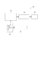
- FIG. 2 shows a schematic diagram of an exemplary apparatus for measuring transient PL.
- the transient PL measurement apparatus 100 of the present embodiment includes a pulse laser unit 101 that can irradiate light of a predetermined wavelength, a sample chamber 102 that houses a measurement sample, a spectrometer 103 that separates light emitted from the measurement sample, A streak camera 104 for forming a two-dimensional image and a personal computer 105 for capturing and analyzing the two-dimensional image are provided. Note that the measurement of the transient PL is not limited to the apparatus described in this embodiment.
- the sample accommodated in the sample chamber 102 is obtained by forming a thin film in which a doping material is doped at a concentration of 12 mass% with respect to a matrix material on a quartz substrate.
- the thin film sample accommodated in the sample chamber 102 is irradiated with a pulse laser from the pulse laser unit 101 to excite the doping material.
- the emitted light is extracted in a direction of 90 degrees with respect to the irradiation direction of the excitation light, the extracted light is dispersed by the spectroscope 103, and a two-dimensional image is formed in the streak camera 104.
- a two-dimensional image in which the vertical axis corresponds to time, the horizontal axis corresponds to wavelength, and the bright spot corresponds to emission intensity.
- an emission spectrum in which the vertical axis represents the emission intensity and the horizontal axis represents the wavelength can be obtained.
- an attenuation curve in which the vertical axis represents the logarithm of the emission intensity and the horizontal axis represents time can be obtained.
- a thin film sample A was prepared as described above using the following reference compound H1 as a matrix material and the following reference compound D1 as a doping material, and transient PL measurement was performed.
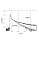
- FIG. 3 shows attenuation curves obtained from the transient PL measured for the thin film sample A and the thin film sample B.
- the transient PL measurement it is possible to obtain a light emission decay curve with the vertical axis representing the emission intensity and the horizontal axis representing the time. Based on this emission decay curve, the fluorescence intensity of fluorescence emitted from the singlet excited state generated by photoexcitation and delayed fluorescence emitted from the singlet excited state generated by reverse energy transfer via the triplet excited state The ratio can be estimated. In the delayed fluorescence emitting material, the ratio of the delayed fluorescence intensity that attenuates slowly is somewhat larger than the fluorescence intensity that decays quickly.
- the delayed fluorescence emission amount in this embodiment can be obtained using the apparatus of FIG.
- the first compound is excited with pulsed light having a wavelength that is absorbed by the first compound (light irradiated from a pulse laser) and then promptly observed from the excited state. After the excitation, there is delay light emission (delayed light emission) that is not observed immediately but is observed thereafter.
- the amount of delay light emission (delayed light emission) is preferably 5% or more with respect to the amount of Promp light emission (immediate light emission).
- the amounts of Prompt light emission and Delay light emission can be obtained by a method similar to the method described in “Nature 492, 234-238, 2012”.
- the apparatus used for calculation of the amount of Promp light emission and Delay light emission is not limited to the apparatus described in the said literature.
- a first compound and the following compound TH-2 are co-deposited on a quartz substrate so that the ratio of the first compound is 12% by mass.
- a sample in which a thin film having a thickness of 100 nm is formed can be used.
- Examples of the first compound according to this embodiment are shown below.
- the first compound in the present invention is not limited to these examples.
- the singlet energy of the second compound according to this embodiment is greater than the singlet energy of the first compound.
- the second compound is a compound containing at least one of a partial structure represented by the following general formula (21) and a partial structure represented by the following general formula (22) in one molecule. Preferably there is.
- Y 21 to Y 26 are each independently a nitrogen atom or a carbon atom bonded to another atom in the molecule of the second compound; Provided that at least one of Y 21 to Y 26 is a carbon atom bonded to another atom in the molecule of the second compound;
- Y 31 to Y 38 are each independently a nitrogen atom or a carbon atom bonded to another atom in the molecule of the second compound; Provided that at least one of Y 31 to Y 38 is a carbon atom bonded to another atom in the molecule of the second compound;
- X 2 is a nitrogen atom, an oxygen atom, or a sulfur atom.
- the partial structure represented by the general formula (21) is at least selected from the group consisting of a group represented by the following general formula (23) and a group represented by the following general formula (24). It is preferable that any group is contained in the second compound. As represented by the following general formula (23) and the following general formula (24), it is possible to keep the energy gap T 77K (M3) at 77 [K] high because the bonding sites are located at the meta positions. Therefore, it is preferable as the second compound.
- Y 21 , Y 22 , Y 24 and Y 26 are each independently a nitrogen atom or CR 21 , R 21 is a hydrogen atom or a substituent, and when R 21 is a substituent, the substituent is A substituted or unsubstituted aromatic hydrocarbon group having 6 to 30 ring carbon atoms, A substituted or unsubstituted heterocyclic group having 5 to 30 ring atoms, A substituted or unsubstituted alkyl group having 1 to 30 carbon atoms, A substituted or unsubstituted fluoroalkyl group having 1 to 30 carbon atoms, A substituted or unsubstituted cycloalkyl group having 3 to 30 carbon atoms, A substituted or unsubstituted aralkyl group having 7 to 30 carbon atoms, Substituted silyl groups, Substituted germanium groups, Substituted phosphine oxide groups, A
- Y 21 , Y 22 , Y 24 and Y 26 are preferably independently CR 21 , and a plurality of R 21 may be the same. May be different.
- Y 22 , Y 24 and Y 26 are preferably independently CR 21 , and a plurality of R 21 are the same or different. May be.
- the substituted germanium group is preferably represented by —Ge (R 101 ) 3 .
- R 101 is each independently a substituent.
- Substituent R 101 is preferably a substituted or unsubstituted alkyl group having 1 to 30 carbon atoms, or a substituted or unsubstituted aromatic hydrocarbon group having 6 to 30 ring carbon atoms.
- the plurality of R 101 may be the same as or different from each other.
- the partial structure represented by the general formula (22) includes a group represented by the following general formula (25), a group represented by the following general formula (26), and the following general formula (27). And at least any one selected from the group consisting of a group represented by the following general formula (28), a group represented by the following general formula (29), and a group represented by the following general formula (20a) Such a group is preferably contained in the second compound.
- Y 31 , Y 32 , Y 33 , Y 34 , Y 35 , Y 36 , Y 37 , and Y 38 are each independently a nitrogen atom or CR 22 ;
- R 22 is a hydrogen atom or a substituent, and when R 22 is a substituent, the substituent is A substituted or unsubstituted aromatic hydrocarbon group having 6 to 30 ring carbon atoms, A substituted or unsubstituted heterocyclic group having 5 to 30 ring atoms, A substituted or unsubstituted alkyl group having 1 to 30 carbon atoms, A substituted or unsubstituted fluoroalkyl group having 1 to 30 carbon atoms, A substituted or unsubstituted cycloalkyl group having 3 to 30 carbon atoms, A substituted or unsubstituted aralkyl group having 7 to 30 carbon atoms, Substituted silyl groups, Sub
- Y 31 to Y 38 are preferably each independently CR 22
- Y 31 to Y 35 , Y 37 and Y 38 are preferably each independently CR 22
- Y 31 , Y 32 , Y 34 , Y 35 , Y 37 and Y 38 are respectively independently, is preferably CR 22, wherein the general formula (29), Y 32 ⁇ Y 38 are each independently preferably an CR 22, wherein the general formula (20a), Y 32 ⁇ Y
- Each of 37 is preferably independently CR 22
- a plurality of R 22 may be the same or different.
- the second compound preferably includes a group represented by the following general formula (20A). Positioning the bonding site as represented by the following general formula (20A) is preferable as the second compound because the energy gap T 77K at 77 [K] can be kept high.
- Y 21 , Y 22 , Y 24 and Y 26 are each independently a nitrogen atom or CR 21 , Y 31 , Y 32 and Y 34 to Y 38 are each independently a nitrogen atom, CR 22 , or a carbon atom bonded to another atom in the molecule of the second compound;
- R 21 and R 22 are each independently a hydrogen atom or a substituent, and when R 21 and R 22 are a substituent, the substituent is A substituted or unsubstituted aromatic hydrocarbon group having 6 to 30 ring carbon atoms, A substituted or unsubstituted heterocyclic group having 5 to 30 ring atoms, A substituted or unsubstituted alkyl group having 1 to 30 carbon atoms, A substituted or unsubstituted fluoroalkyl group having 1 to 30 carbon atoms, A substituted or unsubstituted cycloalkyl group having 3 to 30 carbon atoms, A substituted or unsub
- Z 21 represents an oxygen atom, a sulfur atom, or CR 51 R 52 .
- X 2 , Y 21 , Y 24 , Y 26 , Y 31 , Y 32 , Y 35 to Y 38 are respectively X 2 , Y 21 , and Y in the general formula (20A).
- Y 24 , Y 26 , Y 31 , Y 32 and Y 35 to Y 38 are synonymous.
- the second compound preferably includes a group represented by the following general formula (20B). Positioning the bonding site as represented by the following general formula (20B) is preferable as the second compound because the energy gap T 77K at 77 [K] can be kept high.
- Y 21 , Y 22 , Y 24 and Y 26 are each independently a nitrogen atom or CR 21 , and Y 31 , Y 32 , Y 34 , Y 35 , Y 37 and Y 38 are each independently nitrogen.
- An atom, or CR 22 , Y 41 to Y 45 , Y 47 and Y 48 are each independently a nitrogen atom, CR 24 , or a carbon atom bonded to another atom in the molecule of the second compound;
- R 21 , R 22 , and R 24 are each independently a hydrogen atom or a substituent, and when R 21 , R 22, and R 24 are substituents, the substituent is A substituted or unsubstituted aromatic hydrocarbon group having 6 to 30 ring carbon atoms, A substituted or unsubstituted heterocyclic group having 5 to 30 ring atoms, A substituted or unsubstituted alkyl group having 1 to 30 carbon atoms, A substituted or unsubstituted fluoroalkyl group having 1 to 30 carbon atoms, A substituted or unsubstituted cycloalkyl group having 3 to 30 carbon atoms, A substituted or unsubstituted aralkyl group having 7 to 30 carbon
- Z 22 represents an oxygen atom, a sulfur atom, or CR 51 R 52 .
- X 2 , X 3 , Y 21 , Y 24 , Y 26 , Y 31 , Y 32 , Y 35 , Y 37 , Y 38 , Y 41 to Y 45 , Y 47 and Y 47 48 represents X 2 , X 3 , Y 21 , Y 24 , Y 26 , Y 31 , Y 32 , Y 35 , Y 37 , Y 38 , Y 41 to Y 45 , Y 47 in the general formula (20B), respectively.
- Y 48 .
- the second compound preferably includes a group represented by the following general formula (20C). Positioning the bonding site as represented by the following general formula (20C) is preferable as the second compound because the energy gap T 77K at 77 [K] can be kept high.
- Y 21 , Y 22 , Y 24 and Y 26 are each independently a nitrogen atom or CR 21 , Y 51 , Y 53 , Y 54 and Y 55 are each independently a nitrogen atom or CR 26 ;
- R 21 and R 26 are each independently a hydrogen atom or a substituent, and when R 21 and R 26 are a substituent, the substituent is A substituted or unsubstituted aromatic hydrocarbon group having 6 to 30 ring carbon atoms, A substituted or unsubstituted heterocyclic group having 5 to 30 ring atoms, A substituted or unsubstituted alkyl group having 1 to 30 carbon atoms, A substituted or unsubstituted fluoroalkyl group having 1 to 30 carbon atoms, A substituted or unsubstituted cycloalkyl group having 3 to 30 carbon atoms, A substituted or unsubstituted aralkyl group having 7 to 30 carbon atoms, Sub
- Z 23 represents an oxygen atom, a sulfur atom, or CR 55 R 56 .
- Y 21 , Y 24, Y 26 and Y 53 ⁇ Y 55, respectively, and Y 21, Y 24, Y 26 and Y 53 ⁇ Y 55 in the formula (20C) It is synonymous.
- the second compound preferably includes a group represented by the following general formula (20D). Positioning the bonding site as represented by the following general formula (20D) is preferable as the second compound because the energy gap T 77K at 77 [K] can be kept high.
- Y 21 , Y 22 , Y 24 and Y 26 are each independently a nitrogen atom or CR 21 , Y 51 , Y 53 , Y 54 and Y 55 are each independently a nitrogen atom or CR 26 ; Y 31 to Y 35 , Y 37 and Y 38 are each independently a nitrogen atom, CR 22 , or a carbon atom bonded to another atom in the molecule of the second compound; R 21 , R 22 and R 26 are each independently a hydrogen atom or a substituent, and when R 21 , R 22 and R 26 are a substituent, the substituent is A substituted or unsubstituted aromatic hydrocarbon group having 6 to 30 ring carbon atoms, A substituted or unsubstituted heterocyclic group having 5 to 30 ring atoms, A substituted or unsubstituted alkyl group having 1 to 30 carbon atoms, A substituted or unsubstituted fluoroalkyl group having 1
- X 2 is NR 23 , an oxygen atom, or a sulfur atom
- R 23 is A substituted or unsubstituted aromatic hydrocarbon group having 6 to 30 ring carbon atoms, A substituted or unsubstituted heterocyclic group having 5 to 30 ring atoms, A substituted or unsubstituted alkyl group having 1 to 30 carbon atoms, A substituted or unsubstituted fluoroalkyl group having 1 to 30 carbon atoms, A substituted or unsubstituted cycloalkyl group having 3 to 30 carbon atoms, A substituted or unsubstituted aralkyl group having 7 to 30 carbon atoms, Substituted silyl groups, Substituted germanium groups, Substituted phosphine oxide groups, Fluorine atom, A cyano group, A substituent selected from the group consisting of a nitro group and a carboxy group, provided that the substituted
- Z 24 represents an oxygen atom, a sulfur atom, or CR 55 R 56 .
- X 2 , Y 21 , Y 24 , Y 26 , Y 31 to Y 35 , Y 37 , Y 38 and Y 53 to Y 55 are respectively represented by the general formula (20D). It is synonymous with X 2 , Y 21 , Y 24 , Y 26 , Y 31 to Y 35 , Y 37 , Y 38 and Y 53 to Y 55 .
- Z 25 represents an oxygen atom, a sulfur atom, or CR 59 R 60 .
- X 2 , Y 21 , Y 22 , Y 24 , Y 26 , Y 31 to Y 35 , Y 38 and Y 53 to Y 55 are respectively represented by the general formula (20D).
- X 2 , Y 21 , Y 22 , Y 24 , Y 26 , Y 31 to Y 35 , Y 38 and Y 53 to Y 55 are synonymous.
- the second compound preferably includes a group represented by the following general formula (20E). Positioning the bonding site as represented by the following general formula (20E) is preferable as the second compound because the energy gap T 77K at 77 [K] can be kept high.
- Y 31 , Y 32 , Y 34 , Y 35 , Y 37 and Y 38 are each independently a nitrogen atom or CR 22 ; Y 41 to Y 45 , Y 47 and Y 48 are each independently a nitrogen atom, CR 24 , or a carbon atom bonded to another atom in the molecule of the second compound; R 22 and R 24 are each independently a hydrogen atom or a substituent, and when R 22 and R 24 are a substituent, the substituent is A substituted or unsubstituted aromatic hydrocarbon group having 6 to 30 ring carbon atoms, A substituted or unsubstituted heterocyclic group having 5 to 30 ring atoms, A substituted or unsubstituted alkyl group having 1 to 30 carbon atoms, A substituted or unsubstituted fluoroalkyl group having 1 to 30 carbon atoms, A substituted or unsubstituted cycloalkyl group having 3 to 30 carbon
- the second compound is a group represented by the following general formula (20F), a group represented by the following general formula (20G), and a group represented by the following general formula (20H). At least any group may be contained.
- Y 21 , Y 22 , Y 24 , Y 26 , Y 31 to Y 38 , Y 41 to Y 48 , Y 61 to Y 65 , Y 67 and Y 68 are each independently a nitrogen atom, CR 27 , or a carbon atom bonded to another atom in the molecule of the second compound;
- R 27 is each independently a hydrogen atom or a substituent, and when R 27 is a substituent, the substituent is A substituted or unsubstituted aromatic hydrocarbon group having 6 to 30 ring carbon atoms, A substituted or unsubstituted heterocyclic group having 5 to 30 ring atoms, A substituted or unsubstituted alkyl group having 1 to 30 carbon atoms, A substituted or unsubstituted fluoroalkyl group having 1 to 30 carbon atoms, A substituted or unsubstituted cycloalky
- X 2 is preferably an oxygen atom or a sulfur atom, and more preferably an oxygen atom.
- X 3 is preferably an oxygen atom or a sulfur atom, and more preferably an oxygen atom.
- X 4 is preferably an oxygen atom or a sulfur atom, and more preferably an oxygen atom. Further, it is preferable that the X 2 and the X 3 is an oxygen atom. Further, it is preferable that the X 2 and the X 4 is an oxygen atom.
- R 21 , R 22 , R 24 , R 26 and R 27 are each independently a hydrogen atom or a substituent, and R 21 , R 22 , R 24 , R 26 and R 27 are a fluorine atom, a cyano group, a substituted or unsubstituted alkyl group having 1 to 30 carbon atoms, or a substituted or unsubstituted aromatic hydrocarbon having 6 to 30 ring carbon atoms.
- a substituent selected from the group consisting of a group and a substituted or unsubstituted heterocyclic group having 5 to 30 ring atoms is preferable.
- R 21 , R 22 , R 24 , R 26 and R 27 are each a hydrogen atom, a cyano group, a substituted or unsubstituted aromatic hydrocarbon group having 6 to 30 ring carbon atoms, or a substituted or unsubstituted group. It is more preferably a substituted heterocyclic group having 5 to 30 ring atoms. However, the substituted or unsubstituted aromatic hydrocarbon group having 6 to 30 ring carbon atoms in R 21 , R 22 , R 24 , R 26 and R 27 is a non-condensed ring.
- R 23 , R 25 and R 28 are each independently a substituted or unsubstituted aromatic hydrocarbon group having 6 to 30 ring carbon atoms and a substituted or unsubstituted ring forming atom. It is preferably a substituent selected from the group consisting of 5 to 30 heterocyclic groups, and is a substituted or unsubstituted aromatic hydrocarbon group having 6 to 20 ring-forming carbon atoms, and a substituted or unsubstituted ring formation. More preferred is a substituent selected from the group consisting of heterocyclic groups having 5 to 20 atoms. However, the substituted or unsubstituted aromatic hydrocarbon group having 6 to 30 ring carbon atoms in R 23 , R 25 and R 28 is a non-condensed ring.
- R 51 to R 62 are each independently a substituted or unsubstituted alkyl group having 1 to 30 carbon atoms, a substituted or unsubstituted aromatic hydrocarbon group having 6 to 30 ring carbon atoms, And a substituent selected from the group consisting of substituted or unsubstituted heterocyclic groups having 5 to 30 ring atoms, preferably substituted or unsubstituted alkyl groups having 1 to 20 carbon atoms, substituted or unsubstituted It is more preferably a substituent selected from the group consisting of: an aromatic hydrocarbon group having 6 to 20 ring carbon atoms, and a substituted or unsubstituted heterocyclic group having 5 to 20 ring atoms.
- the substituted or unsubstituted aromatic hydrocarbon group having 6 to 30 ring carbon atoms in R 51 to R 62 is a non-condensed ring.
- the second compound is produced by the method described in, for example, International Publication No. 2012/153780 (WO2012 / 153780A1) and International Publication No. 2013/038650 (WO2013-038650A1). be able to.
- aromatic hydrocarbon group examples include phenyl group, tolyl group, xylyl group, naphthyl group, phenanthryl group, pyrenyl group, chrysenyl group, benzo [c] phenanthryl group, benzo [g] chrysenyl group Group, benzoanthryl group, triphenylenyl group, fluorenyl group, 9,9-dimethylfluorenyl group, benzofluorenyl group, dibenzofluorenyl group, biphenyl group, terphenyl group, quarterphenyl group, fluoranthenyl group
- a phenyl group, a biphenyl group, a terphenyl group, a quarterphenyl group, a naphthyl group, a triphenylenyl group, a fluorenyl group and the like can be mentioned.
- aromatic hydrocarbon group having a substituent examples include a tolyl group, a xylyl group, and a 9,9-dimethylfluorenyl group.
- aryl groups include both fused and non-fused aryl groups.
- aromatic hydrocarbon group a phenyl group, a biphenyl group, a terphenyl group, a quarterphenyl group, a naphthyl group, a triphenylenyl group, and a fluorenyl group are preferable.
- aromatic heterocyclic group examples include pyrrolyl group, pyrazolyl group, pyrazinyl group, pyrimidinyl group, pyridazinyl group, pyridyl group, triazinyl group, indolyl group, Isoindolyl group, imidazolyl group, benzimidazolyl group, indazolyl group, imidazo [1,2-a] pyridinyl group, furyl group, benzofuranyl group, isobenzofuranyl group, dibenzofuranyl group, azadibenzofuranyl group, thiophenyl group, Benzothiophenyl group, dibenzothiophenyl group, azadibenzothiophenyl group, quinolyl group, isoquinolyl group, quinoxalinyl group, quinazolinyl group, naphth
- Examples thereof include a dibenzofuranyl group, a dibenzothiophenyl group, a carbazolyl group, a pyridyl group, a pyrimidinyl group, a triazinyl group, an azadibenzofuranyl group, and an azadibenzothiophenyl group.
- dibenzofuranyl group, dibenzothiophenyl group, carbazolyl group, pyridyl group, pyrimidinyl group, triazinyl group, azadibenzofuranyl group, azadibenzothiophenyl group are preferable, dibenzofuranyl group, dibenzofuranyl group A thiophenyl group, an azadibenzofuranyl group, and an azadibenzothiophenyl group are more preferable.
- the substituted silyl group is preferably a substituted or unsubstituted trialkylsilyl group, a substituted or unsubstituted arylalkylsilyl group, or a substituted or unsubstituted triarylsilyl group.
- Specific examples of the substituted or unsubstituted trialkylsilyl group include a trimethylsilyl group and a triethylsilyl group.
- Specific examples of the substituted or unsubstituted arylalkylsilyl group include a diphenylmethylsilyl group, a ditolylmethylsilyl group, and a phenyldimethylsilyl group.
- Specific examples of the substituted or unsubstituted triarylsilyl group include a triphenylsilyl group and a tolylsilylsilyl group.
- the substituted phosphine oxide group is preferably a substituted or unsubstituted diarylphosphine oxide group.
- Specific examples of the substituted or unsubstituted diarylphosphine oxide group include a diphenylphosphine oxide group and a ditolylphosphine oxide group.
- the third compound of the present embodiment is a fluorescent compound, and the emission color and emission wavelength are not particularly limited.
- the third compound preferably exhibits red, yellow, green, or blue fluorescence, more preferably exhibits red, yellow, or green fluorescence, and exhibits yellow or green fluorescence. Is more preferable, and it is particularly preferable that green fluorescence is emitted.
- the third compound preferably exhibits fluorescence emission having a main peak wavelength of 500 nm or more and 600 nm or less, and more preferably exhibits fluorescence emission of a main peak wavelength of 510 nm or more and 550 nm or less.
- the third compound emits light having a main peak wavelength exceeding 600 nm.
- the main peak wavelength is the peak of the emission spectrum where the emission intensity in the measured emission spectrum is maximum for a toluene solution in which the compound to be measured is dissolved at a concentration of 10 ⁇ 5 mol / liter to 10 ⁇ 6 mol / liter.
- the third compound is preferably a material having a high fluorescence quantum yield.
- Fluorescent material can be used as the third compound of this embodiment.
- the third compound according to this embodiment it is preferable to use a compound containing at least one of the partial structures represented by the following general formula (3) in one molecule.
- the third compound includes a plurality of partial structures represented by the following general formula (3), the plurality of partial structures may be the same as or different from each other.
- X 3 represents a substituted or unsubstituted condensed aromatic hydrocarbon group having 10 to 40 ring carbon atoms
- Ar 11 and Ar 12 are each independently A group selected from the group consisting of a substituted or unsubstituted aromatic hydrocarbon group having 6 to 40 ring carbon atoms and a substituted or unsubstituted heterocyclic group having 5 to 30 ring atoms
- L 11 , L 12 , and L 13 each independently represent a single bond or a linking group, and when L 11 , L 12 , and L 13 are linking groups, Selected from the group consisting of a substituted or unsubstituted aromatic hydrocarbon group having 6 to 30 ring carbon atoms and a substituted or unsubstituted heterocyclic group having 5 to 30 ring atoms
- p represents an integer of 1 to 4.
- Ar 11 and X 3 may be bonded to each other to form a ring.
- L 12 and L 13 are single bonds
- X 3 represents naphthalene, phenanthrene, fluoranthene, anthracene, pyrene, perylene, coronene, chrysene, picene, diphenylanthracene, fluorene, triphenylene, rubicene, benzoanthracene, phenylanthracene, bisanthracene, dian It is preferably a residue of a condensed aromatic hydrocarbon ring selected from the group consisting of tolylbenzene, dibenzoanthracene, benzofluorene, indenofluorene, and benzindenofluorene.
- the second compound when X 3 is an anthracene residue, the second compound is preferably a 9,10-substituted anthracene or a 2,6-substituted anthracene.
- the second compound when X 3 is a pyrene residue, the second compound is preferably 1,6-substituted pyrene or 3,8-substituted pyrene.
- the second compound When X 3 is a chrysene residue, the second compound is preferably a 6,12-substituted chrysene.
- the partial structure represented by the general formula (3) is preferably a group represented by the following general formula (3A).
- X 3 , Ar 11 , Ar 12 , L 11 , L 12 , L 13 , and p are each independently X 3 , Ar 11 , Ar 12 , L 11, L 12, L 13 , and is synonymous with p.
- a wavy line portion represents a bonding position with another atom or another structure in the molecule of the second compound.
- the third compound is also preferably a compound represented by the following general formula (30).
- a is an integer of 0 or 1
- Ar 1 , Ar 2 , R 121 , R 122 , R 123 , R 124 , R 125 , R 126 , R 127 , and R 128 Is a group represented by the following general formula (31)
- Ar 1 , Ar 2 , R 121 , R 122 , R 123 , R 124 , R 125 , R 126 , R 127 , R 128 , R 131 , R 132 , R 133 , R 134 , R 135 , R 136 , R 137 , and R 138 are groups represented by the following general formula (31), Ar 1 , Ar 2 , R 121 , R 122 , R 123 , R 124 , R 125 , R 126 , R 127 , R 128 , R 131 , R 132 , R 133 , R 134 , R 135 , R 136 , R 137
- L 11 , L 12 , and L 13 each independently represent a single bond or a linking group, and when L 11 to L 13 are linking groups, Selected from the group consisting of a substituted or unsubstituted aromatic hydrocarbon group having 6 to 30 ring carbon atoms and a substituted or unsubstituted heterocyclic group having 5 to 30 ring atoms;
- Ar 11 and Ar 12 are each independently It is a group selected from the group consisting of a substituted or unsubstituted aromatic hydrocarbon group having 6 to 30 ring carbon atoms and a substituted or unsubstituted heterocyclic group having 5 to 30 ring atoms.
- the a is preferably 0, and the Ar 1 and Ar 2 are preferably groups represented by the general formula (31).
- a is 0 and R 122 and R 126 are a group represented by the general formula (31).
- the a is 1, and the Ar 1 and Ar 2 are groups represented by the general formula (31).
- the substituents Ar 1 , Ar 2 , R 121 to R 128 , and R 131 to R 138 are substituted or unsubstituted aromatic hydrocarbon groups having 6 to 30 ring carbon atoms, substituted or unsubstituted Unsubstituted heterocyclic group having 5 to 30 ring atoms, substituted or unsubstituted alkyl group having 1 to 30 carbon atoms, substituted silyl group, cyano group, and substituted or unsubstituted trifluoroalkyl having 1 to 20 carbon atoms It is preferably selected from the group consisting of groups.
- the third compound is produced, for example, according to the method described in International Publication No. 2004/092111 (WO2004 / 092111A1) and International Publication No. 2011/0956506 (WO2011 / 0956506A1). can do.
- the second compound is considered to have a function as a dispersion material that suppresses molecular association of the first compounds according to the above-described embodiment in the light emitting layer.
- the first compound according to this embodiment is a thermally active delayed fluorescent material, it tends to cause molecular association.
- the excitation energy (singlet energy or triplet energy) of the molecular aggregate is smaller than that of the monomer. Therefore, when the concentration of the first compound is increased in the thin film, molecular association occurs, and when a fluorescent material, particularly a green to blue fluorescent material, is used, It becomes difficult to move the excitation energy efficiently.
- the second compound in the excited state is unstable compared to the first compound and the third compound. Therefore, it is preferable that the second compound does not participate in exciton generation or carrier transport in the light emitting layer.
- a second compound is specific from the selection criteria of the material to be contained in the light emitting layer in the conventional organic EL device.
- a material having a high electrical and photochemical function is selected and contained in the light emitting layer.
- it is not involved in exciton generation or carrier transport. This is because the second compound is intentionally included in the light emitting layer.
- the singlet energy S (M1) of the first compound is preferably larger than the singlet energy S (M3) of the third compound. That is, it is preferable to satisfy the relationship of S (M3) ⁇ S (M1) ⁇ S (M2).
- the energy gap T 77K (M1) at 77 [K] of the first compound is larger than the energy gap T 77K (M3) at 77 [K] of the third compound, and the second compound It is preferable that the energy gap T 77K (M2) at 77 [K] of the compound is larger than the energy gap T 77K (M1) at 77 [K] of the first compound. That is, it is preferable to satisfy the relationship of T 77K (M3) ⁇ T 77K (M1) ⁇ T 77K (M2).
- the energy gap T 77K (M2) at 77 [K] of the second compound is preferably 2.9 eV or more.
- the second compound can be hardly involved in exciton generation and carrier transport in the light emitting layer.
- TADF mechanism In the organic EL device of the present embodiment, it is preferable to use a compound having a small ⁇ ST (M1) as the first compound, and from the triplet level of the first compound by the thermal energy given from the outside, Inverse crossing to singlet levels easily occurs.
- An energy state conversion mechanism in which the excited triplet state of the electrically excited exciton inside the organic EL element is spin-exchanged to the excited singlet state by crossing between inverse terms is called a TADF mechanism.
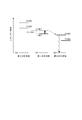
- FIG. 4 is a diagram illustrating an example of the relationship between the energy levels of the first compound, the second compound, and the third compound in the light emitting layer.
- S0 represents the ground state
- S1 (M1) represents the lowest excited singlet state of the first compound
- T1 (M1) represents the lowest excited triplet state of the first compound
- S1 (M2) represents the lowest excited singlet state of the second compound
- T1 (M2) represents the lowest excited triplet state of the second compound
- S1 (M3) represents the lowest excited third state of the third compound. It represents an excited singlet state
- T1 (M3) represents the lowest excited triplet state of the third compound.
- the dashed arrow from S1 (M1) to S1 (M3) in FIG. 4 represents the Forster energy transfer from the lowest excited singlet state of the first compound to the lowest excited singlet state of the third compound. .
- the difference between the lowest excited singlet state S1 and the lowest excited triplet state T1 is defined as ⁇ ST.
- M1 compound having a small ⁇ ST
- the lowest excited triplet state T1 (M1) is reversed to the lowest excited singlet state S1 (M1) by thermal energy. Intersection is possible.
- the Forster energy transfer then occurs from the lowest excited singlet state S1 (M1) of the first compound to the lowest excited singlet state S1 (M3) of the third compound.
- fluorescence emission from the lowest excited singlet state S1 (M3) of the third compound can be observed. It is believed that the internal efficiency can theoretically be increased to 100% also by utilizing delayed fluorescence due to this TADF mechanism.
- the third compound emits light mainly in the light emitting layer 5 when the organic EL element 1 of the present embodiment emits light.
- the film thickness of the light emitting layer 5 in the organic EL element 1 of this embodiment becomes like this.
- they are 5 nm or more and 50 nm or less, More preferably, they are 7 nm or more and 50 nm or less, More preferably, they are 10 nm or more and 50 nm or less. If the thickness is less than 5 nm, it is difficult to form the light-emitting layer 5 and the adjustment of chromaticity may be difficult. If the thickness exceeds 50 nm, the driving voltage may increase.
- the content rate of the first compound is preferably 10% by mass or more and 80% by mass or less
- the second compound The content of is preferably 10% by mass or more and 80% by mass or less
- the content of the third compound is preferably 1% by mass or more and 10% by mass or less.
- the upper limit of the total content of the first compound, the second compound, and the third compound in the light emitting layer 5 is 100% by mass.
- this embodiment does not exclude that the light emitting layer 5 includes materials other than the first compound, the second compound, and the third compound.
- the substrate 2 is used as a support for the organic EL element 1.
- the substrate 2 for example, glass, quartz, plastic, or the like can be used.
- a flexible substrate may be used.
- the flexible substrate is a substrate that can be bent (flexible), and is made of, for example, polycarbonate, polyarylate, polyethersulfone, polypropylene, polyester, polyvinyl fluoride, polyvinyl chloride, polyimide, or polyethylene naphthalate. Examples include a plastic substrate.
- an inorganic vapor deposition film can also be used.
- anode For the anode 3 formed on the substrate 2, it is preferable to use a metal, an alloy, an electrically conductive compound, a mixture thereof, or the like having a high work function (specifically, 4.0 eV or more). Specifically, for example, indium oxide-tin oxide (ITO), indium oxide-tin oxide containing silicon or silicon oxide, indium oxide-zinc oxide, tungsten oxide, and indium oxide containing zinc oxide. And graphene.
- ITO indium oxide-tin oxide
- ITO indium oxide-tin oxide containing silicon or silicon oxide
- indium oxide-zinc oxide silicon oxide
- tungsten oxide tungsten oxide
- indium oxide containing zinc oxide and graphene.
- Au gold
- platinum (Pt) nickel
- Ni tungsten
- W chromium
- Mo molybdenum
- iron (Fe) iron
- cobalt Co
- copper copper
- Pd palladium
- Ti titanium
- a metal material nitride for example, titanium nitride
- indium oxide containing tungsten oxide and zinc oxide contains 0.5% by mass to 5% by mass of tungsten oxide and 0.1% by mass to 1% by mass of zinc oxide with respect to indium oxide.
- a target it can be formed by a sputtering method.
- the hole injection layer 6 formed in contact with the anode 3 is made of a composite material that facilitates hole injection regardless of the work function of the anode 3.
- a material that can be used as an electrode material for example, a metal, an alloy, an electrically conductive compound, and a mixture thereof, and other elements belonging to Group 1 or Group 2 of the periodic table
- an element belonging to Group 1 or Group 2 of the periodic table which is a material having a low work function, that is, an alkali metal such as lithium (Li) or cesium (Cs), and magnesium (Mg), calcium (Ca), or strontium Alkaline earth metals such as (Sr), and alloys containing these (eg, MgAg, AlLi), rare earth metals such as europium (Eu), ytterbium (Yb), and alloys containing these can also be used.
- an alkali metal such as lithium (Li) or cesium (Cs)
- Mg magnesium
- Ca calcium
- strontium Alkaline earth metals such as (Sr)
- alloys containing these eg, MgAg, AlLi
- rare earth metals such as europium
- anode 3 when forming the anode 3 using an alkali metal, an alkaline earth metal, and an alloy containing these, a vacuum evaporation method and a sputtering method can be used. Furthermore, when using a silver paste etc., the apply
- the hole injection layer 6 is a layer containing a substance having a high hole injection property.
- Substances with high hole injection properties include molybdenum oxide, titanium oxide, vanadium oxide, rhenium oxide, ruthenium oxide, chromium oxide, zirconium oxide, hafnium oxide, tantalum oxide, silver oxide, Tungsten oxide, manganese oxide, or the like can be used.
- As a substance having a high hole-injecting property 4,4 ′, 4 ′′ -tris (N, N-diphenylamino) triphenylamine (abbreviation: TDATA), 4,4 ′, which is a low-molecular organic compound, is used.
- a high molecular compound an oligomer, a dendrimer, a polymer, or the like
- a high molecular compound an oligomer, a dendrimer, a polymer, or the like
- PVK poly (N-vinylcarbazole)
- PVTPA poly (4-vinyltriphenylamine)
- PTPDMA poly [N- (4- ⁇ N ′-[4- (4-diphenylamino)] Phenyl] phenyl-N′-phenylamino ⁇ phenyl) methacrylamide]
- PTPDMA poly [N, N′-bis (4-butylphenyl) -N, N′-bis (phenyl) benzidine]
- High molecular compounds such as Poly-TPD
- a polymer compound to which an acid such as poly (3,4-ethylenedioxythiophene) / poly (styrenesulfonic acid) (PEDOT / PSS), polyaniline / poly (styrenesulfonic acid) (PAni / PSS) is added is used. You can also.
- the hole transport layer 7 is a layer containing a substance having a high hole transport property.
- an aromatic amine compound, a carbazole derivative, an anthracene derivative, or the like can be used.
- NPB 4,4′-bis [N- (1-naphthyl) -N-phenylamino] biphenyl
- TPD 4,4′-bis (3-methylphenyl) -N, N′— Diphenyl- [1,1′-biphenyl] -4,4′-diamine
- BAFLP 4-phenyl-4 ′-(9-phenylfluoren-9-yl) triphenylamine
- BAFLP 4-phenyl-4 ′-bis [N- (9,9-dimethylfluoren-2-yl) -N-phenylamino] biphenyl
- DFLDPBi 4,4 ′, 4′, 4
- the substances described here are mainly substances having a hole mobility of 10 ⁇ 6 cm 2 / Vs or higher.
- the hole transport layer 7 includes CBP, 9- [4- (N-carbazolyl)] phenyl-10-phenylanthracene (CzPA), 9-phenyl-3- [4- (10-phenyl-9-anthryl) phenyl
- CBP 9- [4- (N-carbazolyl)] phenyl-10-phenylanthracene
- CzPA 9-phenyl-3- [4- (10-phenyl-9-anthryl) phenyl
- a carbazole derivative such as -9H-carbazole (PCzPA) or an anthracene derivative such as t-BuDNA, DNA, or DPAnth may be used.
- a high molecular compound such as poly (N-vinylcarbazole) (abbreviation: PVK) or poly (4-vinyltriphenylamine) (abbreviation: PVTPA) can also be used.
- PVK poly (N-vinylcarbazole)
- PVTPA poly (4-vinyltriphenylamine)
- any substance other than these may be used as long as it has a property of transporting more holes than electrons.
- the layer containing a substance having a high hole-transport property is not limited to a single layer, and may be a layer in which two or more layers containing the above substances are stacked. When two or more hole transport layers are arranged, it is preferable to arrange a layer containing a material having a larger energy gap on the side closer to the light emitting layer 5.
- the hole transport layer 7 has a function of preventing triplet excitons generated in the light emitting layer 5 from diffusing into the hole transport layer and confining the triplet excitons in the light emitting layer 5. Is preferred.
- the electron transport layer 8 is a layer containing a substance having a high electron transport property.
- the electron transport layer 8 includes 1) metal complexes such as aluminum complexes, beryllium complexes, and zinc complexes, 2) heteroaromatic compounds such as imidazole derivatives, benzimidazole derivatives, azine derivatives, carbazole derivatives, and phenanthroline derivatives, and 3) polymers. Compounds can be used.
- Alq tris (4-methyl-8-quinolinolato) aluminum (abbreviation: Almq 3 ), bis (10-hydroxybenzo [h] quinolinato) beryllium (abbreviation: BeBq 2 ),
- a metal complex such as BAlq, Znq, ZnPBO, ZnBTZ, or the like can be used.
- a benzimidazole compound can be suitably used.
- the substances described here are mainly substances having an electron mobility of 10 ⁇ 6 cm 2 / Vs or higher.
- a substance other than the above may be used as the electron transport layer 8 as long as the substance has a higher electron transport property than the hole transport property.
- the electron transport layer 8 is not limited to a single layer, and may be a layer in which two or more layers made of the above substances are stacked.
- a polymer compound can be used for the electron transport layer 8.
- poly [(9,9-dihexylfluorene-2,7-diyl) -co- (pyridine-3,5-diyl)] (abbreviation: PF-Py)
- poly [(9,9-dioctylfluorene-2) , 7-diyl) -co- (2,2′-bipyridine-6,6′-diyl)] (abbreviation: PF-BPy) and the like can be used.
- the electron transport layer 8 prevents triplet excitons generated in the light emitting layer 5 from diffusing into the electron transport layer 8 and the electron injection layer 9 and confines the triplet excitons in the light emitting layer 5. It preferably has a function.
- the electron injection layer 9 is a layer containing a substance having a high electron injection property.
- the electron injection layer 9 includes lithium (Li), cesium (Cs), calcium (Ca), lithium fluoride (LiF), cesium fluoride (CsF), calcium fluoride (CaF 2 ), lithium oxide (LiOx).
- Alkali metals, alkaline earth metals, or compounds thereof can be used.
- a substance in which an alkali metal, an alkaline earth metal, or a compound thereof is contained in a substance having an electron transporting property specifically, a substance in which magnesium (Mg) is contained in Alq may be used. In this case, electron injection from the cathode 4 can be performed more efficiently.
- a composite material obtained by mixing an organic compound and an electron donor (donor) may be used for the electron injection layer 9.
- a composite material is excellent in electron injecting property and electron transporting property because electrons are generated in the organic compound by the electron donor.
- the organic compound is preferably a material excellent in transporting the generated electrons.
- a substance (metal complex, heteroaromatic compound, etc.) constituting the electron transport layer 8 described above is used.
- the electron donor may be any substance that exhibits an electron donating property to the organic compound.
- alkali metals, alkaline earth metals, and rare earth metals are preferable, and lithium, cesium, magnesium, calcium, erbium, ytterbium, and the like can be given.
- Alkali metal oxides and alkaline earth metal oxides are preferable, and lithium oxide, calcium oxide, barium oxide, and the like can be given.
- a Lewis base such as magnesium oxide can also be used.
- an organic compound such as tetrathiafulvalene (abbreviation: TTF) can be used.
- the cathode 4 is preferably made of a metal, an alloy, an electrically conductive compound, a mixture thereof, or the like having a low work function (specifically, 3.8 eV or less).
- cathode materials include elements belonging to Group 1 or Group 2 of the periodic table of elements, that is, alkali metals such as lithium (Li) and cesium (Cs), and magnesium (Mg) and calcium (Ca ), Alkaline earth metals such as strontium (Sr), and alloys containing these (for example, rare earth metals such as MgAg, AlLi), europium (Eu), ytterbium (Yb), and alloys containing these.
- the cathode 4 when forming the cathode 4 using an alkali metal, alkaline-earth metal, and an alloy containing these, a vacuum evaporation method and sputtering method can be used. Moreover, when using a silver paste etc., the apply
- the cathode 4 by providing the electron injection layer 9, the cathode 4 can be formed using various conductive materials such as indium oxide-tin oxide containing Al, Ag, ITO, graphene, silicon, or silicon oxide regardless of the work function. Can be formed. These conductive materials can be formed by a sputtering method, an inkjet method, a spin coating method, or the like.
- a method for forming each layer of the organic EL element 1 of the present embodiment is not limited to those described above, and a known method such as a dry film forming method or a wet film forming method can be employed.
- a dry film forming method include a vacuum deposition method, a sputtering method, a plasma method, and an ion plating method.
- the wet film forming method include a spin coating method, a dipping method, a flow coating method, and an ink jet method.
- the film thickness of each organic layer of the organic EL element 1 of the present embodiment is not limited except as specifically mentioned above. In general, if the film thickness is too thin, defects such as pinholes are likely to occur. Conversely, if the film thickness is too thick, a high applied voltage is required and the efficiency deteriorates. Therefore, the film thickness is preferably in the range of several nm to 1 ⁇ m.
- the number of ring-forming carbon atoms constitutes the ring itself of a compound having a structure in which atoms are bonded in a cyclic manner (for example, a monocyclic compound, a condensed ring compound, a bridged compound, a carbocyclic compound, or a heterocyclic compound). Represents the number of carbon atoms in the atom.
- the carbon contained in the substituent is not included in the number of ring-forming carbons.
- the “ring-forming carbon number” described below is the same unless otherwise specified.
- the benzene ring has 6 ring carbon atoms
- the naphthalene ring has 10 ring carbon atoms
- the pyridinyl group has 5 ring carbon atoms
- the furanyl group has 4 ring carbon atoms.
- the carbon number of the alkyl group is not included in the number of ring-forming carbons.
- the carbon number of the fluorene ring as a substituent is not included in the number of ring-forming carbons.
- the number of ring-forming atoms means a compound (for example, a monocyclic compound, a condensed ring compound, a bridging compound, a carbocyclic compound, a heterocycle) having a structure in which atoms are bonded in a cyclic manner (for example, a single ring, a condensed ring, or a ring assembly).
- the ring compound represents the number of atoms constituting the ring itself.
- An atom that does not constitute a ring for example, a hydrogen atom that terminates a bond of an atom that constitutes a ring
- an atom contained in a substituent when the ring is substituted by a substituent is not included in the number of ring-forming atoms.
- the “number of ring-forming atoms” described below is the same unless otherwise specified.
- the pyridine ring has 6 ring atoms
- the quinazoline ring has 10 ring atoms
- the furan ring has 5 ring atoms.
- a hydrogen atom bonded to a carbon atom of a pyridine ring or a quinazoline ring or an atom constituting a substituent is not included in the number of ring-forming atoms. Further, when, for example, a fluorene ring is bonded to the fluorene ring as a substituent (including a spirofluorene ring), the number of atoms of the fluorene ring as a substituent is not included in the number of ring-forming atoms.
- each substituent described in the general formula will be described.
- Examples of the aromatic hydrocarbon group having 6 to 30 ring carbon atoms or 6 to 40 ring carbon atoms (sometimes referred to as an aryl group) in the present embodiment include a phenyl group, a biphenyl group, a terphenyl group, Naphthyl, anthryl, phenanthryl, fluorenyl, pyrenyl, chrysenyl, fluoranthenyl, benzo [a] anthryl, benzo [c] phenanthryl, triphenylenyl, benzo [k] fluoranthenyl, benzo Examples include [g] chrycenyl group, benzo [b] triphenylenyl group, picenyl group, perylenyl group, and the like.
- the aryl group preferably has 6 to 20 ring carbon atoms, more preferably 6 to 14 carbon atoms, and still more preferably 6 to 12 carbon atoms.
- a phenyl group, a biphenyl group, a naphthyl group, a phenanthryl group, a terphenyl group, and a fluorenyl group are particularly preferable.
- the 9-position carbon atom is substituted or unsubstituted alkyl group having 1 to 30 carbon atoms in the present embodiment described later or a substituted group.
- an unsubstituted aryl group having 6 to 18 ring carbon atoms is preferably substituted.
- a heterocyclic group having 5 to 30 ring atoms (sometimes referred to as a heteroaryl group, a heteroaromatic ring group, or an aromatic heterocyclic group) has nitrogen, sulfur, oxygen as a heteroatom.
- it contains at least one atom selected from the group consisting of silicon, selenium atom, and germanium atom, and more preferably contains at least one atom selected from the group consisting of nitrogen, sulfur, and oxygen preferable.
- heterocyclic group having 5 to 30 ring atoms in the present embodiment examples include a pyridyl group, pyrimidinyl group, pyrazinyl group, pyridazinyl group, triazinyl group, quinolyl group, isoquinolinyl group, naphthyridinyl group, phthalazinyl group, quinoxalinyl group, Quinazolinyl group, phenanthridinyl group, acridinyl group, phenanthrolinyl group, pyrrolyl group, imidazolyl group, pyrazolyl group, triazolyl group, tetrazolyl group, indolyl group, benzimidazolyl group, indazolyl group, imidazolpyridinyl group, benz Triazolyl, carbazolyl, furyl, thienyl, oxazolyl, thiazolyl, isoxazolyl, isothiazo
- the number of ring-forming atoms of the heterocyclic group is preferably 5-20, and more preferably 5-14.
- the substituted or unsubstituted aryl group having 6 to 30 ring carbon atoms in the present embodiment or substitution is performed on the 9th-position nitrogen atom.
- an unsubstituted heterocyclic group having 5 to 30 ring atoms is preferably substituted.
- the heterocyclic group may be a group derived from a partial structure represented by the following general formulas (XY-1) to (XY-18), for example.
- X and Y are each independently a hetero atom, preferably an oxygen atom, a sulfur atom, a selenium atom, a silicon atom, or a germanium atom.
- the partial structures represented by the general formulas (XY-1) to (XY-18) have a bond at an arbitrary position to be a heterocyclic group, and this heterocyclic group has a substituent. Also good.
- the substituted or unsubstituted carbazolyl group may include, for example, a group in which a ring is further condensed with a carbazole ring represented by the following formula. Such a group may also have a substituent. Also, the position of the joint can be changed as appropriate.
- the alkyl group having 1 to 30 carbon atoms may be linear, branched or cyclic.
- the linear or branched alkyl group include a methyl group, ethyl group, n-propyl group, isopropyl group, n-butyl group, s-butyl group, isobutyl group, t-butyl group, n-pentyl group, n-hexyl group, n-heptyl group, n-octyl group, n-nonyl group, n-decyl group, n-undecyl group, n-dodecyl group, n-tridecyl group, n-tetradecyl group, n-pentadecyl group, n-hexadecyl group, n-heptadecyl group, n-octadecyl group, neopentyl
- the linear or branched alkyl group in the present embodiment preferably has 1 to 10 carbon atoms, and more preferably 1 to 6 carbon atoms.
- An amyl group, an isoamyl group, and a neopentyl group are particularly preferable.
- Examples of the cycloalkyl group having 3 to 30 carbon atoms in the present embodiment include a cyclopropyl group, a cyclobutyl group, a cyclopentyl group, a cyclohexyl group, a 4-methylcyclohexyl group, an adamantyl group, and a norbornyl group.
- the number of carbon atoms forming the ring of the cycloalkyl group is preferably 3 to 10, and more preferably 5 to 8.
- a cyclopentyl group and a cyclohexyl group are particularly preferable.
- halogenated alkyl group in which the alkyl group is substituted with a halogen atom examples include groups in which the alkyl group having 1 to 30 carbon atoms is substituted with one or more halogen atoms. Specific examples include a fluoromethyl group, a difluoromethyl group, a trifluoromethyl group, a fluoroethyl group, a trifluoromethylmethyl group, a trifluoroethyl group, and a pentafluoroethyl group.
- Examples of the substituted silyl group in the present embodiment include an alkylsilyl group having 3 to 30 carbon atoms and an arylsilyl group having 6 to 30 ring carbon atoms.
- Examples of the alkylsilyl group having 3 to 30 carbon atoms in the present embodiment include a trialkylsilyl group having an alkyl group exemplified as the alkyl group having 1 to 30 carbon atoms, specifically, a trimethylsilyl group and a triethylsilyl group.
- the three alkyl groups in the trialkylsilyl group may be the same or different.
- Examples of the arylsilyl group having 6 to 30 ring carbon atoms in the present embodiment include a dialkylarylsilyl group, an alkyldiarylsilyl group, and a triarylsilyl group.
- Examples of the dialkylarylsilyl group include a dialkylarylsilyl group having two alkyl groups exemplified as the alkyl group having 1 to 30 carbon atoms and one aryl group having 6 to 30 ring carbon atoms. .
- the carbon number of the dialkylarylsilyl group is preferably 8-30.
- alkyldiarylsilyl group examples include an alkyldiarylsilyl group having one alkyl group exemplified for the alkyl group having 1 to 30 carbon atoms and two aryl groups having 6 to 30 ring carbon atoms. .
- the alkyldiarylsilyl group preferably has 13 to 30 carbon atoms.
- Examples of the triarylsilyl group include a triarylsilyl group having three aryl groups having 6 to 30 ring carbon atoms.
- the carbon number of the triarylsilyl group is preferably 18-30.
- the alkoxy group having 1 to 30 carbon atoms in this embodiment is represented by —OZ 1 .
- Z 1 include the above alkyl groups having 1 to 30 carbon atoms.
- Examples of the alkoxy group include a methoxy group, an ethoxy group, a propoxy group, a butoxy group, a pentyloxy group, and a hexyloxy group.
- the alkoxy group preferably has 1 to 20 carbon atoms.
- Examples of the halogenated alkoxy group in which the alkoxy group is substituted with a halogen atom include a group in which the alkoxy group having 1 to 30 carbon atoms is substituted with one or more fluorine atoms.
- the aryloxy group having 6 to 30 ring carbon atoms in the present embodiment is represented by —OZ 2 .
- Z 2 include the aryl group having 6 to 30 ring carbon atoms.
- the ring-forming carbon number of the aryloxy group is preferably 6-20.
- Examples of the aryloxy group include a phenoxy group.
- the alkylamino group having 2 to 30 carbon atoms is represented as —NHR V or —N (R V ) 2 .
- Examples of RV include the alkyl group having 1 to 30 carbon atoms.
- the arylamino group having 6 to 60 ring carbon atoms is represented by —NHR W or —N (R W ) 2 .
- R W and an aryl group the ring-forming carbon atoms 6 to 30.
- the alkylthio group having 1 to 30 carbon atoms is represented as —SR V.
- RV include the alkyl group having 1 to 30 carbon atoms.
- the alkylthio group preferably has 1 to 20 carbon atoms.
- An arylthio group having 6 to 30 ring carbon atoms is represented by —SR W. Examples of R W, and an aryl group the ring-forming carbon atoms 6 to 30.
- the ring-forming carbon number of the arylthio group is preferably 6-20.
- halogen atom examples include a fluorine atom, a chlorine atom, a bromine atom, and an iodine atom, and a fluorine atom is preferable.
- ring-forming carbon means a carbon atom constituting a saturated ring, an unsaturated ring, or an aromatic ring.
- Ring-forming atom means a carbon atom and a hetero atom constituting a hetero ring (including a saturated ring, an unsaturated ring, and an aromatic ring).
- the hydrogen atom includes isotopes having different numbers of neutrons, that is, light hydrogen (Protium), deuterium (Deuterium), and tritium (Tritium).
- examples of the substituent include an aryl group, a heterocyclic group, an alkyl group (a linear or branched alkyl group, a cycloalkyl group, a haloalkyl group), an alkylsilyl group as described above.
- an aryl group, a heterocyclic group, an alkyl group, a halogen atom, an alkylsilyl group, an arylsilyl group, and a cyano group are preferable, and further, specific examples that are preferable in the description of each substituent Are preferred.
- substituents include the above aryl group, heterocyclic group, alkyl group, alkylsilyl group, arylsilyl group, alkoxy group, aryloxy group, alkylamino group, arylamino group, alkylthio group, arylthio group, The alkenyl group, alkynyl group, aralkyl group, halogen atom, cyano group, hydroxyl group, nitro group, and carboxy group may be further substituted. A plurality of these substituents may be bonded to each other to form a ring.
- the alkenyl group is preferably an alkenyl group having 2 to 30 carbon atoms, which may be linear, branched or cyclic, such as vinyl group, propenyl group, butenyl group, oleyl group, eicosapentaenyl. Group, docosahexaenyl group, styryl group, 2,2-diphenylvinyl group, 1,2,2-triphenylvinyl group, 2-phenyl-2-propenyl group, cyclopentadienyl group, cyclopentenyl group, cyclohexenyl Group, cyclohexadienyl group and the like.
- the alkynyl group is preferably an alkynyl group having 2 to 30 carbon atoms, which may be linear, branched or cyclic, and examples thereof include ethynyl, propynyl, 2-phenylethynyl and the like.
- an aralkyl group having 6 to 30 ring carbon atoms is preferable, and is represented by —Z 3 —Z 4 .
- Z 3 include an alkylene group corresponding to the alkyl group having 1 to 30 carbon atoms.
- this Z 4 include the above aryl group having 6 to 30 ring carbon atoms.
- This aralkyl group is an aralkyl group having 7 to 30 carbon atoms (the aryl moiety has 6 to 30 carbon atoms, preferably 6 to 20 carbon atoms, more preferably 6 to 12 carbon atoms), and the alkyl moiety has 1 to 30 carbon atoms (preferably 1 to 1 carbon atoms).
- aralkyl group examples include benzyl group, 2-phenylpropan-2-yl group, 1-phenylethyl group, 2-phenylethyl group, 1-phenylisopropyl group, 2-phenylisopropyl group, and phenyl-t-butyl.
- ⁇ -naphthylmethyl group 1- ⁇ -naphthylethyl group, 2- ⁇ -naphthylethyl group, 1- ⁇ -naphthylisopropyl group, 2- ⁇ -naphthylisopropyl group, ⁇ -naphthylmethyl group, 1- ⁇ - Examples include naphthylethyl group, 2- ⁇ -naphthylethyl group, 1- ⁇ -naphthylisopropyl group, and 2- ⁇ -naphthylisopropyl group.
- unsubstituted in the case of “substituted or unsubstituted” means that a hydrogen atom is bonded without being substituted with the substituent.
- carbon number XX to YY in the expression “substituted or unsubstituted ZZ group having XX to YY” represents the number of carbon atoms in the case where the ZZ group is unsubstituted and substituted. In this case, the number of carbon atoms in the substituent is not included.
- “YY” is larger than “XX”, and “XX” and “YY” each mean an integer of 1 or more.
- atom number XX to YY in the expression “a ZZ group having a substituted or unsubstituted atom number XX to YY” represents the number of atoms when the ZZ group is unsubstituted and substituted. In this case, the number of substituent atoms is not included.
- YY is larger than “XX”, and “XX” and “YY” each mean an integer of 1 or more.
- the case of “substituted or unsubstituted” is the same as described above.
- the ring structure when substituents are bonded to each other to form a ring structure, the ring structure is a saturated ring, an unsaturated ring, an aromatic hydrocarbon ring, or a heterocyclic ring.
- examples of the aryl group and heteroaryl group in the linking group include a divalent or higher group obtained by removing one or more atoms from the monovalent group described above.
- examples of the aromatic hydrocarbon ring and the heterocyclic ring include a ring structure derived from the above-described monovalent group.
- An organic EL device material includes a first compound represented by the general formula (1) and a second compound having a singlet energy larger than a singlet energy of the first compound. And a fluorescence-emitting third compound.
- the first compound is preferably a delayed fluorescent compound.
- the second compound and the third compound the same compounds as the second compound and the third compound related to the organic EL element described above can be used.
- the organic EL device material may be composed of only the first compound, the second compound, and the third compound according to the present embodiment, or may be composed of other compounds.
- the light emitting layer of the organic EL device according to one embodiment of the present invention may be formed using the organic EL device material of the present embodiment.
- a method for forming a light emitting layer of an organic EL element using the organic EL element material of the present embodiment for example, a vacuum evaporation method, a molecular beam evaporation method (MBE method), or an organic EL element material is used as a solvent.
- a coating method such as a dipping method of the dissolved solution, a spin coating method, a casting method, a bar coating method, and a roll coating method can be employed.
- the organic EL element 1 can be used for electronic devices such as a display device and a light emitting device.
- the display device include display components such as an organic EL panel module, a television, a mobile phone, a tablet, or a personal computer.
- the light emitting device include lighting or a vehicular lamp.
- the configuration of the organic EL element according to the second embodiment will be described.
- the same components as those in the first embodiment are denoted by the same reference numerals and names, and the description thereof is omitted or simplified.
- materials and compounds not particularly mentioned can be the same materials and compounds as those described in the first embodiment.
- the organic EL device of the second embodiment in the first compound represented by the general formula (10), the L 1 is a single bond, and the R 1 and the R 2 are the same.
- the R 1 and the L 1 are the same, and the R 3 and the R 2 are the same.
- the first compound in the second embodiment can be represented by the following general formula (40), for example.
- the organic EL device of the second embodiment is different from the organic EL device 1 of the first embodiment in that the first compound contained in the light emitting layer is represented by the following general formula (40). Is the same as in the first embodiment.
- the light emitting layer with which the organic EL element of 2nd embodiment is provided contains the 1st compound represented by following General formula (40), and the 2nd compound and 3rd compound demonstrated in 1st embodiment.
- the first compound of this embodiment is preferably a delayed fluorescence compound.
- the first compound of the present embodiment is not a metal complex.
- the light emitting layer preferably does not contain a phosphorescent metal complex, and preferably does not contain any metal complex other than the phosphorescent metal complex.
- R 21 and R 22 are each selected from the group consisting of a substituted or unsubstituted aromatic hydrocarbon group having 6 to 30 ring carbon atoms and a substituted or unsubstituted heterocyclic group having 5 to 30 ring atoms.
- R 21 and R 22 are the same, L 21 and L 22 are each a single bond or a linking group.
- L 21 and L 22 are a linking group, examples of the linking group include substituted or unsubstituted aromatic carbon atoms having 6 to 30 ring carbon atoms.
- a group selected from the group consisting of a hydrogen group and a substituted or unsubstituted heterocyclic group having 5 to 30 ring atoms, and L 21 and L 22 are the same; Y 11 , Y 12 , Y 13 , Y 14 , Y 15 , Y 16 , Y 17 , Y 18 , Y 19 , Y 20 , Y 21 , and Y 22 are each independently a nitrogen atom or CR 13 ; X 1 is an oxygen atom, a sulfur atom, NR 10 , or CR 11 R 12 , R 10 , R 11 , R 12 , and R 13 are each independently a hydrogen atom or a substituent, and when R 10 , R 11 , R 12 , and R 13 are substituents, Independently A substituted or unsubstituted alkyl group having 1 to 30 carbon atoms, A substituted or unsubstituted cycloalkyl group having 3 to 30 carbon atoms, Selected
- L 21 and L 22 are a substituted or unsubstituted aromatic hydrocarbon group having 6 to 30 ring carbon atoms, or a substituted or unsubstituted heterocyclic ring having 5 to 30 ring atoms. It is preferably a group.
- L 21 and L 22 are single bonds, and R 21 and R 22 are the same.
- the general formula (40) is represented by the following general formula (40A).
- Y 11 , Y 12 , Y 13 , Y 14 , Y 15 , Y 16 , Y 17 , Y 18 , Y 19 , Y 20 , Y 21 , Y 22 , and X 1 are respectively Y 11 , Y 12 , Y 13 , Y 14 , Y 15 , Y 16 , Y 17 , Y 18 , Y 19 , Y 20 , Y 21 , Y 22 , and X 1 in the general formula (40). .
- R 21 and R 22 are a substituted or unsubstituted aromatic hydrocarbon group having 6 to 30 ring carbon atoms and a substituted or unsubstituted heterocyclic ring having 5 to 30 ring atoms. It is a group selected from the group consisting of groups and is preferably the same. Further, in the general formula (40A), Y 11 and Y 22 are the same, Y 12 and Y 21 are the same, Y 13 and Y 20 are the same, and Y 14 and Y 19 are It is preferable that Y 15 and Y 18 are the same, and Y 16 and Y 17 are the same.
- Y 11 and Y 22 are the same, Y 12 and Y 21 are the same, Y 13 and Y 20 Are the same, Y 14 and Y 19 are the same, Y 15 and Y 18 are the same, and Y 16 and Y 17 are preferably the same.
- Y 11 , Y 12 , Y 13 , Y 14 , Y 15 , Y 16 , Y 17 , Y 18 , Y 19 , Y 20 , Y 21 , and Y 22 may be CR 13.
- R 13 is more preferably a hydrogen atom.
- R 21 and R 22 are preferably groups represented by the general formula (11).
- R 21 and R 22 are represented by the group represented by the general formula (11a), the group represented by the general formula (11b), and the general formula (11c). It is preferably a group, a group represented by the general formula (11d), or a group represented by the general formula (11e).
- R 21 and R 22 are represented by the group represented by the general formula (11f), the group represented by the general formula (11g), or the general formula (11h). It is preferably a group.
- one or more electron-withdrawing groups are substituted for R 21 and R 22 .
- the electron-withdrawing group the same groups as described above are preferable.
- R 21 and R 22 are preferably a substituted or unsubstituted pyridinyl group, a substituted or unsubstituted pyrimidinyl group, or a substituted or unsubstituted triazinyl group.
- R 2 , R 3 , R 21 , and R 22 are represented by the general formulas (11i), (11j), (11k), (11m), (11n), (11 It is also preferably a group represented by any one of 11p), (11q), (11r), and (11s).
- R 21 and R 22 are preferably a substituted or unsubstituted aromatic hydrocarbon group having 6 to 30 ring carbon atoms, and includes a phenyl group, a biphenyl group, a terphenyl group, and a naphthyl group. More preferred is an aromatic hydrocarbon group selected from the group consisting of a group, a phenanthryl group, and a triphenylenyl group. In this case, it is more preferable that the aromatic hydrocarbon group is substituted with one or more electron-withdrawing groups.
- X 1 is preferably an oxygen atom or a sulfur atom, and more preferably an oxygen atom.
- the light emitting layer is not limited to one layer, and a plurality of light emitting layers may be stacked.
- the organic EL element has a plurality of light emitting layers, it is sufficient that at least one light emitting layer contains the first compound and the second compound.
- the other light-emitting layer may be a fluorescent light-emitting layer or a phosphorescent light-emitting layer that utilizes light emission by electron transition from a triplet excited state to a direct ground state.
- these light emitting layers may be provided adjacent to each other, or a so-called tandem organic material in which a plurality of light emitting units are stacked via an intermediate layer. It may be an EL element.
- a barrier layer may be provided adjacent to the anode side or the cathode side of the light emitting layer.
- the barrier layer is preferably disposed in contact with the light emitting layer and blocks at least one of holes, electrons, and excitons.
- the barrier layer transports electrons, and the holes reach a layer (for example, an electron transport layer) on the cathode side of the barrier layer. Stop that.
- an organic EL element contains an electron carrying layer, it is preferable to contain the said barrier layer between a light emitting layer and an electron carrying layer.
- the barrier layer transports holes, and the electrons reach a layer on the anode side of the barrier layer (for example, a hole transport layer).
- a layer on the anode side of the barrier layer for example, a hole transport layer.
- the organic EL element includes a hole transport layer
- a barrier layer may be provided adjacent to the light emitting layer so that excitation energy does not leak from the light emitting layer to the peripheral layer.
- the excitons generated in the light emitting layer are prevented from moving to a layer (for example, an electron transport layer or a hole transport layer) closer to the electrode than the barrier layer.
- the light emitting layer and the barrier layer are preferably joined.
- the crude product obtained by concentration was purified by silica gel chromatography to obtain a white solid.
- a mixed solvent of hexane and dichloromethane was used as a developing solvent.
- the yield of compound (1-4) was 3.38 g, and the yield was 40%.
- Delayed fluorescence emission was confirmed by measuring transient PL using the apparatus shown in FIG.
- the compound GH-1 and the compound TH-2 were co-evaporated on a quartz substrate so that the ratio of the compound GH-1 was 12% by mass, and a thin film having a thickness of 100 nm was formed to prepare a sample.
- Prompt light emission immediate light emission
- pulsed light light irradiated from a pulse laser
- delay light emission delayed light emission
- the delayed fluorescence emission in this example means that the amount of delay emission (delayed emission) is 5% or more with respect to the amount of Promp emission (immediate emission). It has been confirmed that the amount of Delay luminescence (delayed luminescence) of Compound GH-1 is 5% or more with respect to the amount of Prompt luminescence (immediate luminescence).
- the amounts of Prompt light emission and Delay light emission can be obtained by a method similar to the method described in “Nature 492, 234-238, 2012”.
- the apparatus used for calculation of the amount of Promp light emission and Delay light emission is not limited to the apparatus of FIG. 2, or the apparatus described in literature.
- the singlet energy S was measured as follows. A 10 ⁇ mol / L toluene solution of the compound to be measured was prepared and placed in a quartz cell, and the absorption spectrum (vertical axis: emission intensity, horizontal axis: wavelength) of this sample was measured at room temperature (300 K). A tangent line was drawn with respect to the fall of the absorption spectrum on the long wavelength side, and the singlet energy was calculated by substituting the wavelength value ⁇ edge [nm] at the intersection of the tangent line and the horizontal axis into the following conversion formula 1.
- GH-1 2.89 eV
- GH-2 3.05 eV
- DA 3.55 eV
- Example 1 A glass substrate (manufactured by Geomatic Co., Ltd.) with an ITO transparent electrode (anode) having a thickness of 25 mm ⁇ 75 mm ⁇ 1.1 mm was subjected to ultrasonic cleaning for 5 minutes in isopropyl alcohol, and then UV ozone cleaning was performed for 30 minutes.
- the film thickness of ITO was 130 nm.
- the glass substrate with the transparent electrode line after the cleaning is mounted on a substrate holder of a vacuum evaporation apparatus, and first, the compound HI is vapor-deposited so as to cover the transparent electrode on the surface on which the transparent electrode line is formed. A 5 nm hole injection layer was formed.
- Compound HT-1 was vapor-deposited on the hole injection layer, and a first hole transport layer having a thickness of 80 nm was formed on the HI film.
- Compound HT-2 was vapor-deposited on the first hole transport layer to form a second hole transport layer having a thickness of 10 nm.
- a compound GH-1 as the first compound, a compound DA as the second compound, and GD-1 as the third compound are co-evaporated, A light emitting layer having a thickness of 25 nm was formed.
- the concentration of compound GH-1 in the light emitting layer was 50% by mass
- the concentration of compound DA was 49% by mass
- the concentration of compound GD-1 was 1% by mass.
- Compound HB was vapor-deposited on the light emitting layer to form a 5 nm thick barrier layer.
- a compound ET was vapor-deposited on the barrier layer to form an electron transport layer having a thickness of 20 nm.
- lithium fluoride (LiF) was vapor-deposited on the electron transport layer to form an electron injecting electrode (cathode) having a thickness of 1 nm.
- metal aluminum (Al) was vapor-deposited on this electron injecting electrode, and the metal Al cathode with a film thickness of 80 nm was formed.
- a device arrangement of the organic EL device of Example 1 is schematically shown as follows.
- Example 2 The organic EL device of Example 2 was produced in the same manner as Example 1 except that Compound GD-2 was used instead of Compound GD-1 in the light emitting layer of Example 1.
- a device arrangement of the organic EL device of Example 2 is schematically shown as follows. ITO (130) / HI (5) / HT-1 (80) / HT-2 (10) / DA: GH-1: GD-2 (25, 49%: 50%: 1%) / HB (5) / ET (20) / LiF (1) / Al (80)
- Example 3 The organic EL device of Example 3 was produced in the same manner as in Example 1 except that Compound GD-3 was used instead of Compound GD-1 in the light emitting layer of Example 1.
- a device arrangement of the organic EL device of Example 3 is schematically shown as follows. ITO (130) / HI (5) / HT-1 (80) / HT-2 (10) / DA: GH-1: GD-3 (25, 49%: 50%: 1%) / HB (5) / ET (20) / LiF (1) / Al (80)
- Example 4 The organic EL device of Example 4 was produced in the same manner as in Example 1 except that Compound GD-4 was used instead of Compound GD-1 in the light emitting layer of Example 1.
- a device arrangement of the organic EL device of Example 4 is schematically shown as follows. ITO (130) / HI (5) / HT-1 (80) / HT-2 (10) / DA: GH-1: GD-4 (25, 49%: 50%: 1%) / HB (5) / ET (20) / LiF (1) / Al (80)
- Example 5 The organic EL device of Example 5 was produced in the same manner as Example 1 except that Compound GD-5 was used instead of Compound GD-1 in the light emitting layer of Example 1.
- a device arrangement of the organic EL device of Example 5 is schematically shown as follows. ITO (130) / HI (5) / HT-1 (80) / HT-2 (10) / DA: GH-1: GD-5 (25, 49%: 50%: 1%) / HB (5) / ET (20) / LiF (1) / Al (80)
- Comparative Example 1 The organic EL device of Comparative Example 1 was produced in the same manner as in Example 1 except that Compound GH-2 was used instead of Compound GH-1 in the light emitting layer of Example 1.
- a device arrangement of the organic EL device of Comparative Example 1 is schematically shown as follows. ITO (130) / HI (5) / HT-1 (80) / HT-2 (10) / DA: GH-2: GD-1 (25, 49%: 50%: 1%) / HB (5) / ET (20) / LiF (1) / Al (80)
- Comparative Example 2 The organic EL device of Comparative Example 2 was produced in the same manner as in Example 2 except that Compound GH-2 was used instead of Compound GH-1 in the light emitting layer of Example 2.
- a device arrangement of the organic EL device of Comparative Example 2 is schematically shown as follows. ITO (130) / HI (5) / HT-1 (80) / HT-2 (10) / DA: GH-2: GD-2 (25, 49%: 50%: 1%) / HB (5) / ET (20) / LiF (1) / Al (80)
- Comparative Example 3 The organic EL device of Comparative Example 3 was produced in the same manner as Example 1 except that the compound DA in the light emitting layer of Example 1 was not used.
- a device arrangement of the organic EL device of Comparative Example 3 is schematically shown as follows. ITO (130) / HI (5) / HT-1 (80) / HT-2 (10) / GH-1: GD-1 (25, 99%: 1%) / HB (5) / ET (20) / LiF (1) / Al (80)
- V voltage (unit: V) when current is applied between the ITO transparent electrode and the metal Al cathode so that the current density is 0.1 mA / cm 2 , 1 mA / cm 2 , or 10 mA / cm 2. did.
- Main peak wavelength ⁇ p was determined from the obtained spectral radiance spectrum.
- the organic EL elements according to Examples 1 to 5 have a current efficiency higher than that of the organic EL elements according to Comparative Example 1 and Comparative Example 2 when driven at any current density.
- L / J, power efficiency ⁇ , and external quantum efficiency EQE increased.
- the organic EL devices according to Examples 1 to 5 have a luminous efficiency higher than that of Comparative Example 1 and Comparative Example 2 due to the combination of the first compound, the second compound, and the third compound in the light emitting layer. It is thought that it improved.
- Examples 1 to 5 using GH-1 as the first compound were compared with Comparative Examples 1 and 2 using GH-2 as the first compound, compared with current efficiency L / J, power Efficiency ⁇ and external quantum efficiency EQE were remarkably increased.
- the organic EL device according to Example 1 contains not only the first compound and the third compound but also the second compound in the light emitting layer.
- the organic EL device according to Comparative Example 3 contains the first compound and the third compound in the light emitting layer, but does not contain the second compound. Therefore, it is considered that the organic EL element of Example 1 has improved luminous efficiency compared to the organic EL element according to Comparative Example 3.
- the use of the second compound having a singlet energy higher than that of the first compound and the third compound improves the carrier balance of the entire organic EL device, and the third compound Since concentration quenching due to the use of the compound could also be prevented, it is considered that a highly efficient organic EL device could be obtained as compared with Comparative Example 3.
- Example 6 to 14 For the production of the organic EL devices according to Examples 6 to 14, the following compounds were used in addition to the compounds used in the above Examples.
- the singlet energy was also measured for compound GH-3, compound GH-4, and compound DA-2.
- the measurement method and calculation method are the same as described above.
- the calculated singlet energy S is shown below.
- Example 6 A glass substrate (manufactured by Geomatic Co., Ltd.) with an ITO transparent electrode (anode) having a thickness of 25 mm ⁇ 75 mm ⁇ 1.1 mm was subjected to ultrasonic cleaning for 5 minutes in isopropyl alcohol, and then UV ozone cleaning was performed for 30 minutes.
- the film thickness of ITO was 130 nm.
- the glass substrate with the transparent electrode line after the cleaning is mounted on a substrate holder of a vacuum evaporation apparatus, and first, the compound HI is vapor-deposited so as to cover the transparent electrode on the surface on which the transparent electrode line is formed. A 5 nm hole injection layer was formed.
- Compound HT-1 was vapor-deposited on the hole injection layer, and a first hole transport layer having a thickness of 110 nm was formed on the HI film.
- Compound HT-2 was vapor-deposited on the first hole transport layer to form a second hole transport layer having a thickness of 15 nm.
- a compound GH-1 as the first compound, a compound DA as the second compound, and GD-6 as the third compound are co-deposited on the second hole transport layer, A light emitting layer having a thickness of 25 nm was formed.
- the concentration of compound GH-1 in the light emitting layer was 50% by mass
- the concentration of compound DA was 49% by mass
- the concentration of compound GD-6 was 1% by mass.
- Compound HB was vapor-deposited on the light emitting layer to form a 5 nm thick barrier layer.
- the compound ET was vapor-deposited on the barrier layer to form an electron transport layer having a thickness of 35 nm.
- lithium fluoride (LiF) was vapor-deposited on the electron transport layer to form an electron injecting electrode (cathode) having a thickness of 1 nm.
- metal aluminum (Al) was vapor-deposited on this electron injecting electrode, and the metal Al cathode with a film thickness of 80 nm was formed.
- a device arrangement of the organic EL device of Example 6 is schematically shown as follows.
- Example 7 The organic EL device of Example 7 was the same as that of Example 6 except that Compound GH-3 was used instead of Compound GH-1 in the light emitting layer of Example 6, and Compound GD-7 was used instead of Compound GD-6. 6 was produced in the same manner.
- a device arrangement of the organic EL device of Example 7 is schematically shown as follows. ITO (130) / HI (5) / HT-1 (110) / HT-2 (15) / DA: GH-3: GD-7 (25, 49%: 50%: 1%) / HB (5) / ET (35) / LiF (1) / Al (80)
- Example 8 The organic EL device of Example 8 was produced in the same manner as in Example 6 except that compound GH-4 was used instead of GH-1 in the light emitting layer of Example 6.
- a device arrangement of the organic EL device of Example 5 is schematically shown as follows. ITO (130) / HI (5) / HT-1 (110) / HT-2 (15) / DA: GH-4: GD-6 (25, 49%: 50%: 1%) / HB (5) / ET (35) / LiF (1) / Al (80)
- Example 9 The organic EL device of Example 9 was produced in the same manner as in Example 6 except that Compound GD-8 was used instead of Compound GD-6 in the light emitting layer of Example 6.
- a device arrangement of the organic EL device of Example 9 is schematically shown as follows. ITO (130) / HI (5) / HT-1 (110) / HT-2 (15) / DA: GH-1: GD-8 (25, 49%: 50%: 1%) / HB (5) / ET (35) / LiF (1) / Al (80)
- Example 10 The organic EL device of Example 10 was prepared in the same manner as in Example 6 except that Compound GH-4 was used instead of Compound GH-1 and Compound GD-8 was used instead of Compound GD-6 in the light emitting layer of Example 6. 6 was produced in the same manner.
- a device arrangement of the organic EL device of Example 10 is schematically shown as follows. ITO (130) / HI (5) / HT-1 (110) / HT-2 (15) / DA: GH-4: GD-8 (25, 49%: 50%: 1%) / HB (5) / ET (35) / LiF (1) / Al (80)
- Example 11 A glass substrate (manufactured by Geomatic Co., Ltd.) with an ITO transparent electrode (anode) having a thickness of 25 mm ⁇ 75 mm ⁇ 1.1 mm was subjected to ultrasonic cleaning for 5 minutes in isopropyl alcohol, and then UV ozone cleaning was performed for 30 minutes.
- the film thickness of ITO was 130 nm.
- the glass substrate with the transparent electrode line after the cleaning is mounted on a substrate holder of a vacuum evaporation apparatus, and first, the compound HI is vapor-deposited so as to cover the transparent electrode on the surface on which the transparent electrode line is formed. A 5 nm hole injection layer was formed.
- Compound HT-1 was vapor-deposited on the hole injection layer to form a first hole transport layer having a thickness of 125 nm on the HI film.
- Compound HT-3 was vapor-deposited on the first hole transport layer to form a second hole transport layer having a thickness of 15 nm.
- a compound GH-3 as the first compound, a compound DA as the second compound, and GD-6 as the third compound are co-deposited on the second hole transport layer, A light emitting layer having a thickness of 25 nm was formed.
- the concentration of compound GH-3 in the light emitting layer was 50% by mass
- the concentration of compound DA was 49% by mass
- the concentration of compound GD-6 was 1% by mass.
- Compound HB was vapor-deposited on the light emitting layer to form a 5 nm thick barrier layer.
- the compound ET was vapor-deposited on the barrier layer to form an electron transport layer having a thickness of 35 nm.
- lithium fluoride (LiF) was vapor-deposited on the electron transport layer to form an electron injecting electrode (cathode) having a thickness of 1 nm.
- metal aluminum (Al) was vapor-deposited on this electron injecting electrode, and the metal Al cathode with a film thickness of 80 nm was formed.
- a device arrangement of the organic EL device of Example 11 is schematically shown as follows.
- Example 12 The organic EL device of Example 12 was implemented except that Compound GH-4 was used instead of Compound GH-3 in the light emitting layer of Example 11 and Compound HB-2 was used instead of Compound HB in the barrier layer. Prepared in the same manner as in Example 11.
- a device arrangement of the organic EL device of Example 12 is schematically shown as follows. ITO (130) / HI (5) / HT-1 (125) / HT-3 (15) / DA: GH-4: GD-6 (25, 49%: 50%: 1%) / HB-2 ( 5) / ET (35) / LiF (1) / Al (80)
- Example 13 The organic EL device of Example 13 was produced in the same manner as in Example 11 except that Compound DA-2 was used instead of Compound DA in the light emitting layer of Example 11.
- a device arrangement of the organic EL device of Example 13 is schematically shown as follows. ITO (130) / HI (5) / HT-1 (125) / HT-3 (15) / DA-2: GH-3: GD-6 (25, 49%: 50%: 1%) / HB ( 5) / ET (35) / LiF (1) / Al (80)
- Example 14 The organic EL device of Example 14 uses Compound HT-4 instead of Compound HT-1 in the first hole transport layer of Example 11, and uses Compound GH-4 instead of Compound GH-3 in the light emitting layer. This was prepared in the same manner as in Example 11 except that Compound HB-2 was used instead of Compound HB in the barrier layer.
- a device arrangement of the organic EL device of Example 14 is schematically shown as follows. ITO (130) / HI (5) / HT-4 (125) / HT-3 (15) / DA: GH-4: GD-6 (25, 49%: 50%: 1%) / HB-2 ( 5) / ET (35) / LiF (1) / Al (80)
- the organic EL devices according to Examples 6 to 14 have high current efficiency L / J, power efficiency ⁇ , and external quantum efficiency EQE when driven at any current density. It was.
- the organic EL devices according to Examples 6 to 14 are considered to have improved luminous efficiency due to the combination of the first compound, the second compound, and the third compound in the light emitting layer.
- the main skeleton skeleton represented by the formula (L-1)
- L-1 skeleton represented by the formula (L-1)
- the condensed fused seven-ring ladder skeleton has a stronger donor property than a condensed ring in which about five rings are condensed.
- the electronic states of the HOMO level and the LUMO level are suitable for having thermally activated delayed fluorescence. It is thought that it will be in the state. As a result, energy can be efficiently transferred from the first compound used in Examples 6 to 14 to the fluorescent compound that is the third compound, and a highly efficient organic EL device can be obtained. It is thought that it was made.
- a combination of the first compound, the diaminopyrene derivative or aminofluoranthene derivative which is a fluorescent compound as the third compound, and the dibenzofuran derivative as the second compound was suitable. .
- SYMBOLS 1 Organic EL element, 2 ... Substrate, 3 ... Anode, 4 ... Cathode, 5 ... Light emitting layer, 6 ... Hole injection layer, 7 ... hole transport layer, 8 ... electron transport layer, 9 ... electron injection layer.
Abstract
陽極と、発光層と、陰極と、を含み、前記発光層は、第一の化合物、第二の化合物および第三の化合物を含み、前記第一の化合物は、下記一般式(1)で表される化合物であり、前記第二の化合物の一重項エネルギーは、前記第一の化合物の一重項エネルギーよりも大きく、前記第三の化合物は、蛍光発光性の化合物である有機エレクトロルミネッセンス素子。
Description
本発明は、有機エレクトロルミネッセンス素子、有機エレクトロルミネッセンス素子用材料、および電子機器に関する。
有機エレクトロルミネッセンス素子(以下、「有機EL素子」という場合がある。)に電圧を印加すると、陽極から正孔が、また陰極から電子が、それぞれ発光層に注入される。そして、発光層において、注入された正孔と電子とが再結合し、励起子が形成される。このとき、電子スピンの統計則により、一重項励起子、及び三重項励起子が25%:75%の割合で生成する。
一重項励起子からの発光を用いる蛍光型の有機EL素子は、内部量子効率25%が限界といわれており、携帯電話やテレビ等のフルカラーディスプレイへ応用されつつある。一重項励起子に加えて三重項励起子を利用し、有機EL素子をさらに効率的に発光させることが期待されている。
一重項励起子からの発光を用いる蛍光型の有機EL素子は、内部量子効率25%が限界といわれており、携帯電話やテレビ等のフルカラーディスプレイへ応用されつつある。一重項励起子に加えて三重項励起子を利用し、有機EL素子をさらに効率的に発光させることが期待されている。
このような背景から、遅延蛍光を利用した高効率の蛍光型の有機EL素子が提案され、研究がなされている。
例えば、TADF(Thermally Activated Delayed Fluorescence、熱活性化遅延蛍光)機構が研究されている。このTADF機構は、一重項準位と三重項準位とのエネルギー差(ΔST)の小さな材料を用いた場合に、三重項励起子から一重項励起子への逆項間交差が熱的に生じる現象を利用する機構である。熱活性化遅延蛍光については、例えば、『安達千波矢編、「有機半導体のデバイス物性」、講談社、2012年3月22日、261-262ページ』に記載されている。このTADF機構を利用した有機EL素子が、例えば、特許文献1や非特許文献1に開示されている。
しかしながら、有機EL素子としては、発光効率をさらに向上させる必要がある。
第61回応用物理学会春季学術講演会 講演予稿集 18a-E3-7
第61回応用物理学会春季学術講演会 講演予稿集 18a-E3-8
本発明の目的は、発光効率を向上させることのできる有機エレクトロルミネッセンス素子を提供すること、当該有機エレクトロルミネッセンス素子に用いられる有機エレクトロルミネッセンス素子用材料を提供すること、および当該有機エレクトロルミネッセンス素子を備える電子機器を提供することである。
本発明の一態様によれば、陽極と、発光層と、陰極と、を含み、前記発光層は、第一の化合物、第二の化合物および第三の化合物を含み、前記第一の化合物は、下記一般式(1)で表される化合物であり、前記第二の化合物の一重項エネルギーは、前記第一の化合物の一重項エネルギーよりも大きく、前記第三の化合物は、蛍光発光性の化合物である有機エレクトロルミネッセンス素子が提供される。

(前記一般式(1)において、Xaは、酸素原子、硫黄原子、NR1、またはCR3R4であり、Xb,Xc,Xd,およびXeは、それぞれ独立に、単結合、酸素原子、硫黄原子、NR1、またはCR3R4であり、ただし、Xa,Xb,Xc,Xd,およびXeの少なくとも一つは、NR1であり、XbおよびXcが同時に単結合となることはなく、XdおよびXeが同時に単結合となることはなく、R1は、水素原子、または置換基であり、R1が置換基である場合の置換基は、置換もしくは無置換の炭素数1~30のアルキル基、置換もしくは無置換の環形成炭素数3~30のシクロアルキル基、置換もしくは無置換の環形成炭素数6~30の芳香族炭化水素基、置換もしくは無置換の環形成原子数5~30の複素環基、および-L1-R2で表される基からなる群から選択され、L1は、単結合、または連結基であり、L1が連結基である場合の連結基は、置換もしくは無置換の環形成炭素数6~30の芳香族炭化水素基、および置換もしくは無置換の環形成原子数5~30の複素環基からなる群から選択され、R2~R4は、それぞれ独立に、水素原子、または置換基であり、R2~R4が置換基である場合の置換基は、それぞれ独立に、置換もしくは無置換の炭素数1~30のアルキル基、置換もしくは無置換の環形成炭素数3~30のシクロアルキル基、置換もしくは無置換の環形成炭素数6~30の芳香族炭化水素基、および置換もしくは無置換の環形成原子数5~30の複素環基からなる群から選択され、Z1,Z2,Z3,およびZ4は、それぞれ独立に、置換もしくは無置換の環形成炭素数6~30の芳香族炭化水素環、および置換もしくは無置換の環形成原子数5~30の複素環からなる群から選択される環構造である。)
また、本発明の一態様によれば、前述の本発明の一態様に係る有機エレクトロルミネッセンス素子を備える電子機器が提供される。
また、本発明の一態様によれば、前記一般式(1)で表される第一の化合物と、前記第一の化合物の一重項エネルギーよりも大きい一重項エネルギーを有する第二の化合物と、蛍光発光性の第三の化合物とを含む有機エレクトロルミネッセンス素子用材料が提供される。
本発明の一態様によれば、発光効率を向上させることのできる有機エレクトロルミネッセンス素子を提供すること、当該有機エレクトロルミネッセンス素子に用いられる有機エレクトロルミネッセンス素子用材料を提供すること、および当該有機エレクトロルミネッセンス素子を備える電子機器を提供することができる。
〔第一実施形態〕
(有機EL素子の素子構成)
本実施形態に係る有機EL素子は、一対の電極間に有機層を備える。この有機層は、有機化合物で構成される層少なくとも一層からなる。あるいは、この有機層は、有機化合物で構成される複数の層が積層されてなる。有機層は、無機化合物をさらに含んでいてもよい。本実施形態の有機EL素子において、有機層のうち少なくとも一層は、発光層である。ゆえに、有機層は、例えば、一つの発光層で構成されていてもよいし、正孔注入層、正孔輸送層、電子注入層、電子輸送層、障壁層等の有機EL素子で採用され得る層を含んでいてもよい。
(有機EL素子の素子構成)
本実施形態に係る有機EL素子は、一対の電極間に有機層を備える。この有機層は、有機化合物で構成される層少なくとも一層からなる。あるいは、この有機層は、有機化合物で構成される複数の層が積層されてなる。有機層は、無機化合物をさらに含んでいてもよい。本実施形態の有機EL素子において、有機層のうち少なくとも一層は、発光層である。ゆえに、有機層は、例えば、一つの発光層で構成されていてもよいし、正孔注入層、正孔輸送層、電子注入層、電子輸送層、障壁層等の有機EL素子で採用され得る層を含んでいてもよい。
有機EL素子の代表的な素子構成としては、例えば、次の(a)~(e)などの構成を挙げることができる。
(a)陽極/発光層/陰極
(b)陽極/正孔注入・輸送層/発光層/陰極
(c)陽極/発光層/電子注入・輸送層/陰極
(d)陽極/正孔注入・輸送層/発光層/電子注入・輸送層/陰極
(e)陽極/正孔注入・輸送層/発光層/障壁層/電子注入・輸送層/陰極
上記の中で(d)の構成が好ましく用いられる。ただし、本発明は、これらの構成に限定されない。なお、上記「発光層」とは、発光機能を有する有機層である。前記「正孔注入・輸送層」は「正孔注入層および正孔輸送層のうちの少なくともいずれか1つ」を意味する。前記「電子注入・輸送層」は「電子注入層および電子輸送層のうちの少なくともいずれか1つ」を意味する。有機EL素子が、正孔注入層および正孔輸送層を有する場合には、正孔輸送層と陽極との間に正孔注入層が設けられていることが好ましい。また、有機EL素子が電子注入層および電子輸送層を有する場合には、電子輸送層と陰極との間に電子注入層が設けられていることが好ましい。また、正孔注入層、正孔輸送層、電子輸送層および電子注入層は、それぞれ、一層で構成されていてもよいし、複数の層で構成されていてもよい。
図1に、本実施形態における有機EL素子の一例の概略構成を示す。
有機EL素子1は、透光性の基板2と、陽極3と、陰極4と、陽極3と陰極4との間に配置された有機層10と、を含む。有機層10は、陽極3側から順に、正孔注入層6、正孔輸送層7、発光層5、電子輸送層8、および電子注入層9が、この順番で積層されて構成される。
有機EL素子1は、透光性の基板2と、陽極3と、陰極4と、陽極3と陰極4との間に配置された有機層10と、を含む。有機層10は、陽極3側から順に、正孔注入層6、正孔輸送層7、発光層5、電子輸送層8、および電子注入層9が、この順番で積層されて構成される。
(発光層)
有機EL素子1の発光層5は、第一の化合物、第二の化合物、および第三の化合物を含む。発光層5は、金属錯体を含んでもよいが、本実施形態では、燐光発光性の金属錯体を含まないことが好ましく、燐光発光性の金属錯体以外の金属錯体も含まないことが好ましい。
有機EL素子1の発光層5は、第一の化合物、第二の化合物、および第三の化合物を含む。発光層5は、金属錯体を含んでもよいが、本実施形態では、燐光発光性の金属錯体を含まないことが好ましく、燐光発光性の金属錯体以外の金属錯体も含まないことが好ましい。
<第一の化合物>
本実施形態の第一の化合物は、下記一般式(1)で表される化合物である。第一の化合物は、遅延蛍光発光性の化合物であることが好ましい。本実施形態の第一の化合物は、金属錯体ではない。
本実施形態の第一の化合物は、下記一般式(1)で表される化合物である。第一の化合物は、遅延蛍光発光性の化合物であることが好ましい。本実施形態の第一の化合物は、金属錯体ではない。

前記一般式(1)において、
Xaは、酸素原子、硫黄原子、NR1、またはCR3R4であり、
Xb,Xc,Xd,およびXeは、それぞれ独立に、単結合、酸素原子、硫黄原子、NR1、またはCR3R4であり、
ただし、Xa,Xb,Xc,Xd,およびXeの少なくとも一つは、NR1であり、XbおよびXcが同時に単結合となることはなく、XdおよびXeが同時に単結合となることはなく、
R1は、水素原子、または置換基であり、R1が置換基である場合の置換基は、
置換もしくは無置換の炭素数1~30のアルキル基、
置換もしくは無置換の環形成炭素数3~30のシクロアルキル基、
置換もしくは無置換の環形成炭素数6~30の芳香族炭化水素基、
置換もしくは無置換の環形成原子数5~30の複素環基、および
-L1-R2で表される基からなる群から選択され、
L1は、単結合、または連結基であり、L1が連結基である場合の連結基は、置換もしくは無置換の環形成炭素数6~30の芳香族炭化水素基、および置換もしくは無置換の環形成原子数5~30の複素環基からなる群から選択され、
R2~R4は、それぞれ独立に、水素原子、または置換基であり、R2~R4が置換基である場合の置換基は、それぞれ独立に、
置換もしくは無置換の炭素数1~30のアルキル基、
置換もしくは無置換の環形成炭素数3~30のシクロアルキル基、
置換もしくは無置換の環形成炭素数6~30の芳香族炭化水素基、および
置換もしくは無置換の環形成原子数5~30の複素環基からなる群から選択され、
Z1,Z2,Z3,およびZ4は、それぞれ独立に、
置換もしくは無置換の環形成炭素数6~30の芳香族炭化水素環、および
置換もしくは無置換の環形成原子数5~30の複素環からなる群から選択される環構造である。
なお、本明細書において、Xeが表すのは、キセノンの元素記号ではない。
ここで、前記一般式(1)において、Xaと、Z1およびZ2を結ぶ単結合とは、Z1で表される環構造の隣り合う原子、並びにZ2で表される環構造の隣り合う原子に、それぞれ結合する。XbとXcとは、Z2で表される環構造の隣り合う原子、およびZ3で表される環構造の隣り合う原子に、それぞれ結合する。XdとXeとは、Z3で表される環構造の隣り合う原子、およびZ4で表される環構造の隣り合う原子に、それぞれ結合する。
前記一般式(1)において、例えばZ1がベンゼン環である場合、Z1とXaと単結合とは、以下の結合様式を有する(波線部分は、Z2との結合箇所を表す)。
前記一般式(1)において、例えばZ1がベンゼン環である場合、Z1とXaと単結合とは、以下の結合様式を有する(波線部分は、Z2との結合箇所を表す)。

また、前記一般式(1)において、例えば、Z1およびZ2がともにベンゼン環である場合、Z1とXaと単結合とZ2とは、以下のいずれかの結合様式を有する(波線部分は、XbおよびXcとの結合箇所を表す)。

本実施形態において、前記Z1,Z2,Z3,およびZ4は、それぞれ独立に、置換もしくは無置換の環形成炭素数6~30の芳香族炭化水素環であることが好ましく、置換もしくは無置換の環形成炭素数6~20の芳香族炭化水素環であることがより好ましく、ベンゼン環、ナフタレン環、フェナントレン環、およびトリフェニレニレン環からなる群から選択される芳香族炭化水素環であることがさらに好ましく、ベンゼン環であることが特に好ましい。
本実施形態において、前記一般式(1)のXa,Xb,Xc,XdおよびXeのうち2つ以上が、それぞれ独立して、NR1であることが好ましい。さらには、XaがNR1であり、かつXb,Xc,XdおよびXeのうち少なくとも1つ以上がNR1であることも好ましい。
熱活性遅延蛍光性を実現させる有機化合物の一例として、分子内でドナー部位(電子供与性を有する部位)とアクセプター部位(電子受容性を有する部位)とを結合させた化合物が挙げられる。前記一般式(1)で表される第一の化合物が含有する窒素原子が増えると、第一の化合物のドナー部位の電子供与性が高まり、第一の化合物のアクセプター部位の電子受容性とのバランスが好適になる。その結果、第一の化合物は、遅延蛍光発光性の材料として、好ましい性質を有する。
熱活性遅延蛍光性を実現させる有機化合物の一例として、分子内でドナー部位(電子供与性を有する部位)とアクセプター部位(電子受容性を有する部位)とを結合させた化合物が挙げられる。前記一般式(1)で表される第一の化合物が含有する窒素原子が増えると、第一の化合物のドナー部位の電子供与性が高まり、第一の化合物のアクセプター部位の電子受容性とのバランスが好適になる。その結果、第一の化合物は、遅延蛍光発光性の材料として、好ましい性質を有する。
本実施形態において、前記一般式(1A)または前記一般式(1B)で表される化合物は、前記XaおよびXdがNR1であることが好ましい。
また、本実施形態において、前記一般式(1C)または前記一般式(1D)で表される化合物は、前記XaおよびXeがNR1であることが好ましい。
また、本実施形態において、前記一般式(1C)または前記一般式(1D)で表される化合物は、前記XaおよびXeがNR1であることが好ましい。
本実施形態において、前記R1の少なくとも一つは、-L1-R2で表される基であることが好ましい。
本実施形態において、前記第一の化合物は、下記一般式(10)で表されることも好ましい。下記一般式(10)で表される第一の化合物は、高い三重項エネルギーを保持できる結合様式の環を有する。そのため、下記一般式(10)で表される第一の化合物は、特に、青から緑色の波長領域の高い発光エネルギーを発光層内に効率的に閉じ込めることができるので、好ましい。

前記一般式(10)において、
R1,R2,およびL1は、前記一般式(1)におけるR1,R2,およびL1とそれぞれ同義であり、
X1は、酸素原子、硫黄原子、NR10、またはCR11R12であり、
Y11,Y12,Y13,Y14,Y15,Y16,Y17,Y18,Y19,Y20,Y21,およびY22は、それぞれ独立に、窒素原子またはCR13であり、
R10,R11,R12,およびR13は、それぞれ独立に、水素原子または置換基であり、R10,R11,R12,およびR13が置換基である場合の置換基は、それぞれ独立に、
置換もしくは無置換の炭素数1~30のアルキル基、
置換もしくは無置換の炭素数3~30のシクロアルキル基、
置換もしくは無置換の環形成炭素数6~30の芳香族炭化水素基、および
置換もしくは無置換の環形成原子数5~30の複素環基からなる群から選択され、
複数のR13は、互いに同一でも異なっていてもよく、複数のR13のうち少なくとも2つが置換基である場合、置換基R13同士は、互いに結合して環構造が構築されていてもよい。
本実施形態において、前記R1および前記R2は、それぞれ独立に、置換もしくは無置換の環形成炭素数6~30の芳香族炭化水素基、および置換もしくは無置換の環形成原子数5~30の複素環基からなる群から選択される置換基であることが好ましい。
本実施形態において、前記R1と前記-L1-R2で表される基とが、互いに異なることが好ましい。すなわち、前記一般式(10)で表される構造において、窒素原子に結合するR1と、別の窒素原子に結合するL1-R2とが異なることが好ましい。
本実施形態において、前記R1は、無置換の環形成炭素数6~30の芳香族炭化水素基、および無置換の環形成原子数5~30の複素環基からなる群から選択される置換基であり、前記L1は、連結基であることが好ましい。この場合も、前記一般式(10)で表される構造において、窒素原子に結合するR1と、別の窒素原子に結合するL1-R2とが、異なることとなる。
本実施形態において、前記R1は、置換もしくは無置換の環形成炭素数6~30の芳香族炭化水素基であることが好ましく、置換もしくは無置換の環形成炭素数6~20の芳香族炭化水素基であることがより好ましく、フェニル基、ビフェニル基、ターフェニル基、ナフチル基、フェナントリル基、およびトリフェニレニル基からなる群から選択される芳香族炭化水素基であることがさらに好ましい。
本実施形態において、前記第一の化合物は、下記一般式(10A)で表されることも好ましい。

前記一般式(10A)において、X1,Y11,Y12,Y13,Y14,Y15,Y16,Y17,Y18,Y19,Y20,Y21,Y22,L1,R1,およびR2は、それぞれ、前記一般式(10)におけるX1,Y11~Y22,L1,R1,およびR2と同義であり、R3は、置換基であり、置換もしくは無置換の環形成炭素数6~30の芳香族炭化水素基、および置換もしくは無置換の環形成原子数5~30の複素環基からなる群から選択される。
本実施形態において、前記Y11,Y12,Y13,Y14,Y15,Y16,Y17,Y18,Y19,Y20,Y21,Y22は、CR13であることが好ましく、前記R13は、水素原子であることがより好ましい。この場合、例えば、前記一般式(10)は、下記一般式(10B)で表される。

前記一般式(10B)において、X1,L1,R1,およびR2は、それぞれ、前記一般式(1)におけるX1,L1,R1,およびR2と同義である。
本実施形態において、前記X1は、酸素原子または硫黄原子であることが好ましく、酸素原子であることがより好ましい。
本実施形態において、前記R2は、下記一般式(11)で表される基であることが好ましい。

前記一般式(11)において、
Y1~Y5は、それぞれ独立に、窒素原子またはCR14であり、
R14は、水素原子または置換基であり、R14が置換基である場合の置換基としては、
フッ素原子、
シアノ基、
置換もしくは無置換の炭素数1~30のアルキル基、
置換もしくは無置換の炭素数3~30のシクロアルキル基、
置換シリル基、
置換ホスフィンオキシド基、
置換もしくは無置換の環形成炭素数6~30の芳香族炭化水素基、および
置換もしくは無置換の環形成原子数5~30の複素環基からなる群から選択され、
複数のR14は、互いに同一でも異なっていてもよく、複数のR14のうち少なくとも2つが置換基である場合、置換基R14同士は、互いに結合して環構造が構築されていてもよい。
前記一般式(11)において、波線部分は、前記L1との結合箇所を表す。
本実施形態において、前記R2が、前記一般式(11)で表される基である場合、前記一般式(10)は、下記一般式(10C)で表される。

前記一般式(10C)において、X1,Y11,Y12,Y13,Y14,Y15,Y16,Y17,Y18,Y19,Y20,Y21,Y22,L1,およびR1は、それぞれ、前記一般式(10)におけるX1,Y11,Y12,Y13,Y14,Y15,Y16,Y17,Y18,Y19,Y20,Y21,Y22,L1,およびR1と同義であり、Y1,Y2,Y3,Y4,およびY5は、それぞれ、前記一般式(11)におけるY1,Y2,Y3,Y4,およびY5と同義である。
本実施形態において、前記Y1,Y2,Y3,Y4,およびY5は、それぞれ独立に、CR14であることが好ましい。この場合、複数のR14は、互いに同一でも異なっていてもよい。
本実施形態において、前記Y1,Y2,Y3,Y4,およびY5のうち少なくとも一つが窒素原子であることも好ましい。
本実施形態において、前記Y1,Y2,Y3,Y4,およびY5のうち少なくとも一つがCR14であることも好ましく、前記R14の少なくとも一つが、シアノ基であることが好ましい。
本実施形態において、前記R2は、下記一般式(11a)で表される基、下記一般式(11b)で表される基、下記一般式(11c)で表される基、下記一般式(11d)で表される基、または下記一般式(11e)で表される基であることが好ましい。


前記一般式(11a)~(11e)において、Y1~Y5は、それぞれ前記一般式(11)におけるY1~Y5と同義である。前記一般式(11a)~(11e)において、波線部分は、前記L1との結合箇所を表す。
本実施形態において、前記R2は、下記一般式(11f)で表される基、下記一般式(11g)で表される基、または下記一般式(11h)で表される基であることも好ましい。

前記一般式(11g)~(11h)において、Y3は、それぞれ前記一般式(11)におけるY3と同義である。前記一般式(11f)~(11h)において、波線部分は、前記L1との結合箇所を表す。
前記一般式(11a)~(11h)において、前記Y1,Y2,Y3,Y4,およびY5は、それぞれ独立に、CR14であることも好ましい。この場合、R14は、水素原子であることが好ましい。また、R14が置換基であってもよく、置換基R14は、シアノ基以外であることが好ましい。複数の置換基R14がある場合は、互いに同一でも異なっていてもよい。
本実施形態において、前記R2に1つ以上の電子吸引性基が置換されていることも好ましい。電子吸引性基としては、例えば、シアノ基、フルオロ基、ハロゲン化アルキル基、ハロゲン化アルキル置換アルキル基、ニトロ基、カルボニル基等が挙げられる。これらの電子吸引性基の中で、シアノ基、フルオロ基、ハロゲン化アルキル基、またはハロゲン化アルキル置換アルキル基が好ましく、シアノ基がより好ましい。前記R2に置換される電子吸引性基が複数ある場合、互いに同一でも異なっていてもよい。
前記R2にシアノ基が置換される場合、1つまたは2つであることも好ましい。一方で、前記R2にシアノ基が置換される場合、3つ以上であることも好ましい。
前記R2にシアノ基が置換される場合、1つまたは2つであることも好ましい。一方で、前記R2にシアノ基が置換される場合、3つ以上であることも好ましい。
本実施形態において、前記R2は、置換もしくは無置換のピリジニル基、置換もしくは無置換のピリミジニル基、または置換もしくは無置換のトリアジニル基であることも好ましい。例えば、前記R2は、下記一般式(11i),(11j),(11k),(11m),(11n),(11p),(11q),(11r),および(11s)のいずれかで表される基であることも好ましい。


前記一般式(11i),(11j),(11k),(11m),(11n),(11p),(11q),(11r),および(11s)において、Ra,Rb,Rc,およびRdは、それぞれ独立に、水素原子または置換基であり、Ra,Rb,Rc,およびRdが置換基である場合の置換基としては、前記Raが置換基である場合に列挙された置換基の群から選択される。Ra,Rb,Rc,Rdが置換基である場合の置換基としては、シアノ基以外であることが好ましい。
前記一般式(11i),(11j),(11k),(11m),(11n),(11p),(11q),(11r),および(11s)で表される基の中では、例えば、前記一般式(11q)で表される基が好ましく、RaおよびRbは、それぞれ独立に、置換もしくは無置換の環形成炭素数6~30の芳香族炭化水素基、および置換もしくは無置換の環形成原子数5~30の複素環基からなる群から選択されることが好ましく、置換もしくは無置換の環形成炭素数6~20の芳香族炭化水素基、および置換もしくは無置換の環形成原子数5~20の複素環基からなる群から選択されることがより好ましい。前記一般式(11i),(11j),(11k),(11m),(11n),(11p),(11q),(11r),および(11s)において、波線部分は、前記L1との結合箇所を表す。
前記一般式(11i),(11j),(11k),(11m),(11n),(11p),(11q),(11r),および(11s)で表される基の中では、例えば、前記一般式(11q)で表される基が好ましく、RaおよびRbは、それぞれ独立に、置換もしくは無置換の環形成炭素数6~30の芳香族炭化水素基、および置換もしくは無置換の環形成原子数5~30の複素環基からなる群から選択されることが好ましく、置換もしくは無置換の環形成炭素数6~20の芳香族炭化水素基、および置換もしくは無置換の環形成原子数5~20の複素環基からなる群から選択されることがより好ましい。前記一般式(11i),(11j),(11k),(11m),(11n),(11p),(11q),(11r),および(11s)において、波線部分は、前記L1との結合箇所を表す。
本実施形態において、前記L1は、置換もしくは無置換の環形成炭素数6~30の芳香族炭化水素基、および置換もしくは無置換の環形成原子数5~30の複素環基からなる群から選択されることが好ましく、置換もしくは無置換の環形成炭素数6~20の芳香族炭化水素基、および置換もしくは無置換の環形成原子数5~20の複素環基からなる群から選択されることがより好ましい。
また、前記L1は、フェニレン基、ビフェニルジイル基またはナフチレン基であることが好ましく、フェニレン基またはビフェニルジイル基であることがより好ましく、p-フェニレン基がさらに好ましい。前記L1の置換基としては、フェニル基、アルキル基、およびシアノ基の少なくともいずれかが好ましい。
また、前記L1は、フェニレン基、ビフェニルジイル基またはナフチレン基であることが好ましく、フェニレン基またはビフェニルジイル基であることがより好ましく、p-フェニレン基がさらに好ましい。前記L1の置換基としては、フェニル基、アルキル基、およびシアノ基の少なくともいずれかが好ましい。
本実施形態において、置換シリル基は、-Si(R100)3で表されることが好ましい。R100は、それぞれ独立に、置換基である。置換基R100は、置換もしくは無置換の炭素数1~30のアルキル基、および置換もしくは無置換の環形成炭素数6~30の芳香族炭化水素基からなる群から選択されることが好ましい。複数のR100は、互いに同一でも異なっていてもよい。
本実施形態において、置換シリル基は、置換もしくは無置換のトリアルキルシリル基、置換もしくは無置換のアリールアルキルシリル基、および置換もしくは無置換のトリアリールシリル基からなる群から選択される基であることがより好ましい。
本実施形態において、置換シリル基は、置換もしくは無置換のトリアルキルシリル基、置換もしくは無置換のアリールアルキルシリル基、および置換もしくは無置換のトリアリールシリル基からなる群から選択される基であることがより好ましい。
本実施形態において、置換ホスフィンオキシド基は、下記一般式(100)で表されることが好ましい。

前記一般式(100)において、R102およびR103は、それぞれ独立に、置換基である。置換基R102および置換基R103は、それぞれ独立に、置換もしくは無置換の炭素数1~30のアルキル基、および置換もしくは無置換の環形成炭素数6~30の芳香族炭化水素基からなる群から選択されることが好ましい。
本実施形態において、置換ホスフィンオキシド基は、置換もしくは無置換のジアリールホスフィンオキシド基であることがより好ましい。
本実施形態において、置換ホスフィンオキシド基は、置換もしくは無置換のジアリールホスフィンオキシド基であることがより好ましい。
・遅延蛍光発光性
遅延蛍光(熱活性化遅延蛍光)については、「有機半導体のデバイス物性」(安達千波矢編、講談社発行)の261~268ページで解説されている。その文献の中で、蛍光発光材料の励起一重項状態と励起三重項状態のエネルギー差ΔE13を小さくすることができれば、通常は遷移確率が低い励起三重項状態から励起一重項状態への逆エネルギー移動が高効率で生じ、熱活性化遅延蛍光(Thermally Activated delayed Fluorescence, TADF)が発現すると説明されている。さらに、当該文献中の図10.38で、遅延蛍光の発生メカニズムが説明されている。本実施形態における第一の化合物は、このようなメカニズムで発生する熱活性化遅延蛍光を示す化合物である。
遅延蛍光の発光は過渡PL(Photo Luminescence)測定により確認できる。
過渡PL測定から得た減衰曲線に基づいて遅延蛍光の挙動を解析することもできる。過渡PL測定とは、試料にパルスレーザーを照射して励起させ、照射を止めた後のPL発光の減衰挙動(過渡特性)を測定する手法である。TADF材料におけるPL発光は、最初のPL励起で生成する一重項励起子からの発光成分と、三重項励起子を経由して生成する一重項励起子からの発光成分に分類される。最初のPL励起で生成する一重項励起子の寿命は、ナノ秒オーダーであり、非常に短い。そのため、当該一重項励起子からの発光は、パルスレーザーを照射後、速やかに減衰する。
一方、遅延蛍光は、寿命の長い三重項励起子を経由して生成する一重項励起子からの発光のため、ゆるやかに減衰する。このように最初のPL励起で生成する一重項励起子からの発光と、三重項励起子を経由して生成する一重項励起子からの発光とでは、時間的に大きな差がある。そのため、遅延蛍光由来の発光強度を求めることができる。
一方、遅延蛍光は、寿命の長い三重項励起子を経由して生成する一重項励起子からの発光のため、ゆるやかに減衰する。このように最初のPL励起で生成する一重項励起子からの発光と、三重項励起子を経由して生成する一重項励起子からの発光とでは、時間的に大きな差がある。そのため、遅延蛍光由来の発光強度を求めることができる。
図2には、過渡PLを測定するための例示的装置の概略図が示されている。
本実施形態の過渡PL測定装置100は、所定波長の光を照射可能なパルスレーザー部101と、測定試料を収容する試料室102と、測定試料から放射された光を分光する分光器103と、2次元像を結像するためのストリークカメラ104と、2次元像を取り込んで解析するパーソナルコンピュータ105とを備える。なお、過渡PLの測定は、本実施形態で説明する装置に限定されない。
試料室102に収容される試料は、マトリックス材料に対し、ドーピング材料が12質量%の濃度でドープされた薄膜を石英基板に成膜することで得られる。
試料室102に収容された薄膜試料に対し、パルスレーザー部101からパルスレーザーを照射して、ドーピング材料を励起させる。励起光の照射方向に対して90度の方向へ発光を取り出し、取り出した光を分光器103で分光し、ストリークカメラ104内で2次元像を結像する。その結果、縦軸が時間に対応し、横軸が波長に対応し、輝点が発光強度に対応する2次元画像を得ることができる。この2次元画像を所定の時間軸で切り出すと、縦軸が発光強度であり、横軸が波長である発光スペクトルを得ることができる。また、当該2次元画像を波長軸で切り出すと、縦軸が発光強度の対数であり、横軸が時間である減衰曲線(過渡PL)を得ることができる。
例えば、マトリックス材料として、下記参考化合物H1を用い、ドーピング材料として下記参考化合物D1を用いて上述のようにして薄膜試料Aを作製し、過渡PL測定を行った。

ここでは、前述の薄膜試料A、および薄膜試料Bを用いて減衰曲線を解析した。薄膜試料Bは、マトリックス材料として下記参考化合物H2を用い、ドーピング材料として前記参考化合物D1を用いて、上述のようにして薄膜試料を作製した。
図3には、薄膜試料Aおよび薄膜試料Bについて測定した過渡PLから得た減衰曲線が示されている。
図3には、薄膜試料Aおよび薄膜試料Bについて測定した過渡PLから得た減衰曲線が示されている。

上記したように過渡PL測定によって、縦軸を発光強度とし、横軸を時間とする発光減衰曲線を得ることができる。この発光減衰曲線に基づいて、光励起により生成した一重項励起状態から発光する蛍光と、三重項励起状態を経由し、逆エネルギー移動により生成する一重項励起状態から発光する遅延蛍光との、蛍光強度比を見積もることができる。遅延蛍光発光性の材料では、素早く減衰する蛍光の強度に対し、緩やかに減衰する遅延蛍光の強度の割合が、ある程度大きい。
本実施形態における遅延蛍光発光量は、図2の装置を用いて求めることができる。前記第一の化合物は、当該第一の化合物が吸収する波長のパルス光(パルスレーザーから照射される光)で励起された後、当該励起状態から即座に観察されるPrompt発光(即時発光)と、当該励起後、即座には観察されず、その後観察されるDelay発光(遅延発光)とが存在する。本実施形態においては、Delay発光(遅延発光)の量がPrompt発光(即時発光)の量に対して5%以上であることが好ましい。
Prompt発光とDelay発光の量は、“Nature 492, 234-238, 2012”に記載された方法と同様の方法により求めることができる。なお、Prompt発光とDelay発光の量の算出に使用される装置は、前記の文献に記載の装置に限定されない。
また、遅延蛍光発光性の測定に用いられる試料は、例えば、第一の化合物と下記化合物TH-2とを、第一の化合物の割合が12質量%となるように石英基板上に共蒸着し、膜厚100nmの薄膜を形成した試料を使用することができる。

・第一の化合物の製造方法
前記第一の化合物は、例えば、下記実施例に記載した方法により製造することができる。
前記第一の化合物は、例えば、下記実施例に記載した方法により製造することができる。
本実施形態に係る第一の化合物の例を以下に示す。なお、本発明における第一の化合物は、これらの例に限定されない。


<第二の化合物>
本実施形態に係る第二の化合物の一重項エネルギーは、前記第一の化合物の一重項エネルギーよりも大きい。
本実施形態に係る第二の化合物の一重項エネルギーは、前記第一の化合物の一重項エネルギーよりも大きい。
本実施形態において、第二の化合物は、一つの分子中に下記一般式(21)で表される部分構造および下記一般式(22)で表される部分構造のうち少なくともいずれかを含む化合物であることが好ましい。

前記一般式(21)において、
Y21~Y26は、それぞれ独立に、窒素原子、または前記第二の化合物の分子中における他の原子と結合する炭素原子であり、
ただし、Y21~Y26のうち少なくともいずれかは、前記第二の化合物の分子中における他の原子と結合する炭素原子であり、
前記一般式(22)において、
Y31~Y38は、それぞれ独立に、窒素原子、または前記第二の化合物の分子中における他の原子と結合する炭素原子であり、
ただし、Y31~Y38のうち少なくともいずれかは、前記第二の化合物の分子中における他の原子と結合する炭素原子であり、
X2は、窒素原子、酸素原子、または硫黄原子である。
Y21~Y26は、それぞれ独立に、窒素原子、または前記第二の化合物の分子中における他の原子と結合する炭素原子であり、
ただし、Y21~Y26のうち少なくともいずれかは、前記第二の化合物の分子中における他の原子と結合する炭素原子であり、
前記一般式(22)において、
Y31~Y38は、それぞれ独立に、窒素原子、または前記第二の化合物の分子中における他の原子と結合する炭素原子であり、
ただし、Y31~Y38のうち少なくともいずれかは、前記第二の化合物の分子中における他の原子と結合する炭素原子であり、
X2は、窒素原子、酸素原子、または硫黄原子である。
本実施形態において、前記一般式(21)で表される部分構造は、下記一般式(23)で表される基および下記一般式(24)で表される基からなる群から選択される少なくともいずれかの基として前記第二の化合物に含まれることが好ましい。
下記一般式(23)および下記一般式(24)で表されるように、結合箇所が互いにメタ位に位置することは、77[K]におけるエネルギーギャップT77K(M3)を高く保つことができるため、前記第二の化合物として好ましい。
下記一般式(23)および下記一般式(24)で表されるように、結合箇所が互いにメタ位に位置することは、77[K]におけるエネルギーギャップT77K(M3)を高く保つことができるため、前記第二の化合物として好ましい。

前記一般式(23)および前記一般式(24)において、
Y21,Y22,Y24およびY26は、それぞれ独立に、窒素原子、またはCR21であり、
R21は、水素原子または置換基であり、R21が置換基である場合の置換基は、
置換もしくは無置換の環形成炭素数6~30の芳香族炭化水素基、
置換もしくは無置換の環形成原子数5~30の複素環基、
置換もしくは無置換の炭素数1~30のアルキル基、
置換もしくは無置換の炭素数1~30のフルオロアルキル基、
置換もしくは無置換の炭素数3~30のシクロアルキル基、
置換もしくは無置換の炭素数7~30のアラルキル基、
置換シリル基、
置換ゲルマニウム基、
置換ホスフィンオキシド基、
ハロゲン原子、
シアノ基、
ニトロ基、および
カルボキシ基からなる群から選択される置換基であり、ただし、前記R21における置換もしくは無置換の環形成炭素数6~30の芳香族炭化水素基は、非縮合環である。
前記一般式(23)および前記一般式(24)において、波線部分は、前記第二の化合物の分子中における他の原子または他の構造との結合箇所を表す。
本実施形態では、前記一般式(23)において、前記Y21,前記Y22,前記Y24および前記Y26は、それぞれ独立に、CR21であることが好ましく、複数のR21は、同一でも異なっていてもよい。
また、本実施形態では、前記一般式(24)において、前記Y22,前記Y24および前記Y26は、それぞれ独立に、CR21であることが好ましく、複数のR21は、同一でも異なっていてもよい。
また、本実施形態では、前記一般式(24)において、前記Y22,前記Y24および前記Y26は、それぞれ独立に、CR21であることが好ましく、複数のR21は、同一でも異なっていてもよい。
本実施形態において、置換ゲルマニウム基は、-Ge(R101)3で表されることが好ましい。R101は、それぞれ独立に、置換基である。置換基R101は、置換もしくは無置換の炭素数1~30のアルキル基、または置換もしくは無置換の環形成炭素数6~30の芳香族炭化水素基であることが好ましい。複数のR101は、互いに同一でも異なっていてもよい。
本実施形態において、前記一般式(22)で表される部分構造は、下記一般式(25)で表される基,下記一般式(26)で表される基,下記一般式(27)で表される基,下記一般式(28)で表される基,下記一般式(29)で表される基,および下記一般式(20a)で表される基からなる群から選択される少なくともいずれかの基として前記第二の化合物に含まれることが好ましい。


前記一般式(25)~(29),(20a)において、
Y31,Y32,Y33,Y34,Y35,Y36,Y37,およびY38は、それぞれ独立に、窒素原子またはCR22であり、
R22は、水素原子または置換基であり、R22が置換基である場合の置換基は、
置換もしくは無置換の環形成炭素数6~30の芳香族炭化水素基、
置換もしくは無置換の環形成原子数5~30の複素環基、
置換もしくは無置換の炭素数1~30のアルキル基、
置換もしくは無置換の炭素数1~30のフルオロアルキル基、
置換もしくは無置換の炭素数3~30のシクロアルキル基、
置換もしくは無置換の炭素数7~30のアラルキル基、
置換シリル基、
置換ゲルマニウム基、
置換ホスフィンオキシド基、
ハロゲン原子、
シアノ基、
ニトロ基、および
カルボキシ基からなる群から選択される置換基であり、ただし、前記R22における置換もしくは無置換の環形成炭素数6~30の芳香族炭化水素基は、非縮合環であり、
前記一般式(25),(26)において、X2は、窒素原子であり、
前記一般式(27)~(29),(20a)において、X2は、NR23、酸素原子または硫黄原子であり、
R23は、
置換もしくは無置換の環形成炭素数6~30の芳香族炭化水素基、
置換もしくは無置換の環形成原子数5~30の複素環基、
置換もしくは無置換の炭素数1~30のアルキル基、
置換もしくは無置換の炭素数1~30のフルオロアルキル基、
置換もしくは無置換の炭素数3~30のシクロアルキル基、
置換もしくは無置換の炭素数7~30のアラルキル基、
置換シリル基、
置換ゲルマニウム基、
置換ホスフィンオキシド基、
フッ素原子、
シアノ基、
ニトロ基、および
カルボキシ基からなる群から選択される置換基であり、ただし、前記R23における置換もしくは無置換の環形成炭素数6~30の芳香族炭化水素基は、非縮合環である。
前記一般式(25)~(29),(20a)において、波線部分は、前記第二の化合物の分子中における他の原子または他の構造との結合箇所を表す。
本実施形態では、前記一般式(25)において、Y31~Y38は、それぞれ独立に、CR22であることが好ましく、前記一般式(26)および前記一般式(27)において、Y31~Y35,Y37およびY38は、それぞれ独立に、CR22であることが好ましく、前記一般式(28)において、Y31,Y32,Y34,Y35,Y37およびY38は、それぞれ独立に、CR22であることが好ましく、前記一般式(29)において、Y32~Y38は、それぞれ独立に、CR22であることが好ましく、前記一般式(20a)において、Y32~Y37は、それぞれ独立に、CR22であることが好ましく、複数のR22は、同一でも異なっていてもよい。
本実施形態において、第二の化合物は、下記一般式(20A)で表される基を含むことも好ましい。
下記一般式(20A)で表されるように結合箇所が位置することは、77[K]におけるエネルギーギャップT77Kを高く保つことができるため、前記第二の化合物として好ましい。
下記一般式(20A)で表されるように結合箇所が位置することは、77[K]におけるエネルギーギャップT77Kを高く保つことができるため、前記第二の化合物として好ましい。

前記一般式(20A)において、
Y21,Y22,Y24およびY26は、それぞれ独立に、窒素原子、またはCR21であり、
Y31,Y32およびY34~Y38は、それぞれ独立に、窒素原子、CR22、または前記第二の化合物の分子中における他の原子と結合する炭素原子であり、
R21およびR22は、それぞれ独立に、水素原子または置換基であり、R21およびR22が置換基である場合の置換基は、
置換もしくは無置換の環形成炭素数6~30の芳香族炭化水素基、
置換もしくは無置換の環形成原子数5~30の複素環基、
置換もしくは無置換の炭素数1~30のアルキル基、
置換もしくは無置換の炭素数1~30のフルオロアルキル基、
置換もしくは無置換の炭素数3~30のシクロアルキル基、
置換もしくは無置換の炭素数7~30のアラルキル基、
置換シリル基、
置換ゲルマニウム基、
置換ホスフィンオキシド基、
フッ素原子、
シアノ基、
ニトロ基、および
カルボキシ基からなる群から選択される置換基であり、ただし、前記R21および前記R22における置換もしくは無置換の環形成炭素数6~30の芳香族炭化水素基は、非縮合環であり、
X2は、NR23、酸素原子、または硫黄原子であり、
R23は、
置換もしくは無置換の環形成炭素数6~30の芳香族炭化水素基、
置換もしくは無置換の環形成原子数5~30の複素環基、
置換もしくは無置換の炭素数1~30のアルキル基、
置換もしくは無置換の炭素数1~30のフルオロアルキル基、
置換もしくは無置換の炭素数3~30のシクロアルキル基、
置換もしくは無置換の炭素数7~30のアラルキル基、
置換シリル基、
置換ゲルマニウム基、
置換ホスフィンオキシド基、
フッ素原子、
シアノ基、
ニトロ基、および
カルボキシ基からなる群から選択される置換基であり、ただし、前記R23における置換もしくは無置換の環形成炭素数6~30の芳香族炭化水素基は、非縮合環であり、
Y22とY34とは、酸素原子、硫黄原子、またはCR51R52を介して架橋されていてもよく、
Y24とY32とは、酸素原子、硫黄原子、またはCR53R54を介して架橋されていてもよく、
R51~R54は、それぞれ独立に、前記R23が置換基である場合の置換基と同義である。
前記一般式(20A)において、波線部分は、前記第二の化合物の分子中における他の原子または他の構造との結合箇所を表す。
例えば、前記一般式(20A)において、Y22とY34とが、酸素原子、硫黄原子、またはCR51R52を介して架橋される場合は、下記一般式(20A-1)で表される。

ただし、前記一般式(20A-1)において、Z21は、酸素原子、硫黄原子、またはCR51R52である。前記一般式(20A-1)において、X2,Y21,Y24,Y26,Y31,Y32,Y35~Y38は、それぞれ、前記一般式(20A)におけるX2,Y21,Y24,Y26,Y31,Y32,Y35~Y38と同義である。
本実施形態において、前記第二の化合物は、下記一般式(20B)で表される基を含むことも好ましい。
下記一般式(20B)で表されるように結合箇所が位置することは、77[K]におけるエネルギーギャップT77Kを高く保つことができるため、前記第二の化合物として好ましい。
下記一般式(20B)で表されるように結合箇所が位置することは、77[K]におけるエネルギーギャップT77Kを高く保つことができるため、前記第二の化合物として好ましい。

前記一般式(20B)において、
Y21,Y22,Y24およびY26は、それぞれ独立に、窒素原子、またはCR21であり、 Y31,Y32,Y34,Y35,Y37およびY38は、それぞれ独立に、窒素原子、またはCR22であり、
Y41~Y45,Y47およびY48は、それぞれ独立に、窒素原子、CR24、または前記第二の化合物の分子中における他の原子と結合する炭素原子であり、
R21,R22,R24は、それぞれ独立に、水素原子または置換基であり、R21,R22およびR24が置換基である場合の置換基は、
置換もしくは無置換の環形成炭素数6~30の芳香族炭化水素基、
置換もしくは無置換の環形成原子数5~30の複素環基、
置換もしくは無置換の炭素数1~30のアルキル基、
置換もしくは無置換の炭素数1~30のフルオロアルキル基、
置換もしくは無置換の炭素数3~30のシクロアルキル基、
置換もしくは無置換の炭素数7~30のアラルキル基、
置換シリル基、
置換ゲルマニウム基、
置換ホスフィンオキシド基、
フッ素原子、
シアノ基、
ニトロ基、および
カルボキシ基からなる群から選択される置換基であり、ただし、前記R21,前記R22,前記R24における置換もしくは無置換の環形成炭素数6~30の芳香族炭化水素基は、非縮合環であり、
X2は、NR23、酸素原子、または硫黄原子であり、
X3は、NR25、酸素原子、または硫黄原子であり、
R23およびR25は、それぞれ独立に、
置換もしくは無置換の環形成炭素数6~30の芳香族炭化水素基、
置換もしくは無置換の環形成原子数5~30の複素環基、
置換もしくは無置換の炭素数1~30のアルキル基、
置換もしくは無置換の炭素数1~30のフルオロアルキル基、
置換もしくは無置換の炭素数3~30のシクロアルキル基、
置換もしくは無置換の炭素数7~30のアラルキル基、
置換シリル基、
置換ゲルマニウム基、
置換ホスフィンオキシド基、
フッ素原子、
シアノ基、
ニトロ基、および
カルボキシ基からなる群から選択される置換基であり、ただし、前記R23および前記R25における置換もしくは無置換の環形成炭素数6~30の芳香族炭化水素基は、非縮合環であり、
Y22とY34とは、酸素原子、硫黄原子、またはCR51R52を介して架橋されていてもよく、
Y24とY32とは、酸素原子、硫黄原子、またはCR53R54を介して架橋されていてもよく、
R51~R54は、それぞれ独立に、前記R23および前記R25が置換基である場合の置換基と同義である。
前記一般式(20B)において、波線部分は、前記第二の化合物の分子中における他の原子または他の構造との結合箇所を表す。
例えば、前記一般式(20B)において、Y22とY34とが、酸素原子、硫黄原子、またはCR51R52を介して架橋される場合は、下記一般式(20B-1)で表される。

ただし、前記一般式(20B-1)において、Z22は、酸素原子、硫黄原子、またはCR51R52である。前記一般式(20B-1)において、X2,X3,Y21,Y24,Y26,Y31,Y32,Y35,Y37,Y38,Y41~Y45,Y47およびY48は、それぞれ、前記一般式(20B)におけるX2,X3,Y21,Y24,Y26,Y31,Y32,Y35,Y37,Y38,Y41~Y45,Y47およびY48と同義である。
本実施形態において、前記第二の化合物は、下記一般式(20C)で表される基を含むことも好ましい。
下記一般式(20C)で表されるように結合箇所が位置することは、77[K]におけるエネルギーギャップT77Kを高く保つことができるため、前記第二の化合物として好ましい。
下記一般式(20C)で表されるように結合箇所が位置することは、77[K]におけるエネルギーギャップT77Kを高く保つことができるため、前記第二の化合物として好ましい。

前記一般式(20C)において、
Y21,Y22,Y24およびY26は、それぞれ独立に、窒素原子、またはCR21であり、
Y51,Y53,Y54およびY55は、それぞれ独立に、窒素原子、またはCR26であり、
R21およびR26は、それぞれ独立に、水素原子または置換基であり、R21およびR26が置換基である場合の置換基は、
置換もしくは無置換の環形成炭素数6~30の芳香族炭化水素基、
置換もしくは無置換の環形成原子数5~30の複素環基、
置換もしくは無置換の炭素数1~30のアルキル基、
置換もしくは無置換の炭素数1~30のフルオロアルキル基、
置換もしくは無置換の炭素数3~30のシクロアルキル基、
置換もしくは無置換の炭素数7~30のアラルキル基、
置換シリル基、
置換ゲルマニウム基、
置換ホスフィンオキシド基、
フッ素原子、
シアノ基、
ニトロ基、および
カルボキシ基からなる群から選択される置換基であり、ただし、前記R21および前記R26における置換もしくは無置換の環形成炭素数6~30の芳香族炭化水素基は、非縮合環であり、
Y22とY51とは、酸素原子、硫黄原子、またはCR55R56を介して架橋されていてもよく、
Y24とY55とは、酸素原子、硫黄原子、またはCR57R58を介して架橋されていてもよく、
R55~R58は、それぞれ独立に、置換基であり、R55~R58における置換基は、
置換もしくは無置換の環形成炭素数6~30の芳香族炭化水素基、
置換もしくは無置換の環形成原子数5~30の複素環基、
置換もしくは無置換の炭素数1~30のアルキル基、
置換もしくは無置換の炭素数1~30のフルオロアルキル基、
置換もしくは無置換の炭素数3~30のシクロアルキル基、
置換もしくは無置換の炭素数7~30のアラルキル基、
置換シリル基、
置換ゲルマニウム基、
置換ホスフィンオキシド基、
フッ素原子、
シアノ基、
ニトロ基、および
カルボキシ基からなる群から選択される置換基であり、ただし、前記R55~R58における置換もしくは無置換の環形成炭素数6~30の芳香族炭化水素基は、非縮合環である。
前記一般式(20C)において、波線部分は、前記第二の化合物の分子中における他の原子または他の構造との結合箇所を表す。
例えば、前記一般式(20C)において、Y22とY51とが、酸素原子、硫黄原子、またはCR55R56を介して架橋される場合は、下記一般式(20C-1)で表される。

ただし、前記一般式(20C-1)において、Z23は、酸素原子、硫黄原子、またはCR55R56である。前記一般式(20C-1)において、Y21,Y24,Y26およびY53~Y55は、それぞれ、前記一般式(20C)におけるY21,Y24,Y26およびY53~Y55と同義である。
本実施形態において、前記第二の化合物は、下記一般式(20D)で表される基を含むことも好ましい。
下記一般式(20D)で表されるように結合箇所が位置することは、77[K]におけるエネルギーギャップT77Kを高く保つことができるため、前記第二の化合物として好ましい。
下記一般式(20D)で表されるように結合箇所が位置することは、77[K]におけるエネルギーギャップT77Kを高く保つことができるため、前記第二の化合物として好ましい。

前記一般式(20D)において、
Y21,Y22,Y24およびY26は、それぞれ独立に、窒素原子、またはCR21であり、
Y51,Y53,Y54およびY55は、それぞれ独立に、窒素原子、またはCR26であり、
Y31~Y35,Y37およびY38は、それぞれ独立に、窒素原子、CR22、または前記第二の化合物の分子中における他の原子と結合する炭素原子であり、
R21,R22およびR26は、それぞれ独立に、水素原子または置換基であり、R21,R22およびR26が置換基である場合の置換基は、
置換もしくは無置換の環形成炭素数6~30の芳香族炭化水素基、
置換もしくは無置換の環形成原子数5~30の複素環基、
置換もしくは無置換の炭素数1~30のアルキル基、
置換もしくは無置換の炭素数1~30のフルオロアルキル基、
置換もしくは無置換の炭素数3~30のシクロアルキル基、
置換もしくは無置換の炭素数7~30のアラルキル基、
置換シリル基、
置換ゲルマニウム基、
置換ホスフィンオキシド基、
フッ素原子、
シアノ基、
ニトロ基、および
カルボキシ基からなる群から選択される置換基であり、ただし、前記R21,前記R22および前記R26における置換もしくは無置換の環形成炭素数6~30の芳香族炭化水素基は、非縮合環であり、
X2は、NR23、酸素原子、または硫黄原子であり、
R23は、
置換もしくは無置換の環形成炭素数6~30の芳香族炭化水素基、
置換もしくは無置換の環形成原子数5~30の複素環基、
置換もしくは無置換の炭素数1~30のアルキル基、
置換もしくは無置換の炭素数1~30のフルオロアルキル基、
置換もしくは無置換の炭素数3~30のシクロアルキル基、
置換もしくは無置換の炭素数7~30のアラルキル基、
置換シリル基、
置換ゲルマニウム基、
置換ホスフィンオキシド基、
フッ素原子、
シアノ基、
ニトロ基、および
カルボキシ基からなる群から選択される置換基であり、ただし、前記R23における置換もしくは無置換の環形成炭素数6~30の芳香族炭化水素基は、非縮合環であり、
Y22とY51とは、酸素原子、硫黄原子、またはCR55R56を介して架橋されていてもよく、
Y24とY55とは、酸素原子、硫黄原子、またはCR57R58を介して架橋されていてもよく、
Y51とY37とは、酸素原子、硫黄原子、またはCR59R60を介して架橋されていてもよく、
Y53とY35とは、酸素原子、硫黄原子、またはCR61R62を介して架橋されていてもよく、
R55~R62は、それぞれ独立に、前記R23が置換基である場合の置換基と同義である。 前記一般式(20D)において、波線部分は、前記第二の化合物の分子中における他の原子または他の構造との結合箇所を表す。
例えば、前記一般式(20D)において、Y22とY51とが、酸素原子、硫黄原子、またはCR55R56を介して架橋される場合は、下記一般式(20D-1)で表される。

ただし、前記一般式(20D-1)において、Z24は、酸素原子、硫黄原子、またはCR55R56である。前記一般式(20D-1)において、X2,Y21,Y24,Y26,Y31~Y35,Y37,Y38およびY53~Y55は、それぞれ、前記一般式(20D)におけるX2,Y21,Y24,Y26,Y31~Y35,Y37,Y38およびY53~Y55と同義である。
例えば、前記一般式(20D)において、Y51とY37とが、酸素原子、硫黄原子、またはCR59R60を介して架橋される場合は、下記一般式(20D-2)で表される。

ただし、前記一般式(20D-2)において、Z25は、酸素原子、硫黄原子、またはCR59R60である。前記一般式(20D-2)において、X2,Y21,Y22,Y24,Y26,Y31~Y35,Y38およびY53~Y55は、それぞれ、前記一般式(20D)におけるX2,Y21,Y22,Y24,Y26,Y31~Y35,Y38およびY53~Y55と同義である。
本実施形態において、前記第二の化合物は、下記一般式(20E)で表される基を含むことも好ましい。
下記一般式(20E)で表されるように結合箇所が位置することは、77[K]におけるエネルギーギャップT77Kを高く保つことができるため、前記第二の化合物として好ましい。
下記一般式(20E)で表されるように結合箇所が位置することは、77[K]におけるエネルギーギャップT77Kを高く保つことができるため、前記第二の化合物として好ましい。

前記一般式(20E)において、
Y31,Y32,Y34,Y35,Y37およびY38は、それぞれ独立に、窒素原子、またはCR22であり、
Y41~Y45,Y47およびY48は、それぞれ独立に、窒素原子、CR24、または前記第二の化合物の分子中における他の原子と結合する炭素原子であり、
R22およびR24は、それぞれ独立に、水素原子または置換基であり、R22およびR24が置換基である場合の置換基は、
置換もしくは無置換の環形成炭素数6~30の芳香族炭化水素基、
置換もしくは無置換の環形成原子数5~30の複素環基、
置換もしくは無置換の炭素数1~30のアルキル基、
置換もしくは無置換の炭素数1~30のフルオロアルキル基、
置換もしくは無置換の炭素数3~30のシクロアルキル基、
置換もしくは無置換の炭素数7~30のアラルキル基、
置換シリル基、
置換ゲルマニウム基、
置換ホスフィンオキシド基、
フッ素原子、
シアノ基、
ニトロ基、および
カルボキシ基からなる群から選択される置換基であり、ただし、前記R22および前記R24における置換もしくは無置換の環形成炭素数6~30の芳香族炭化水素基は、非縮合環であり、
X2は、NR23、酸素原子、または硫黄原子であり、
X3は、NR25、酸素原子、または硫黄原子であり、
R23およびR25は、それぞれ独立に、
置換もしくは無置換の環形成炭素数6~30の芳香族炭化水素基、
置換もしくは無置換の環形成原子数5~30の複素環基、
置換もしくは無置換の炭素数1~30のアルキル基、
置換もしくは無置換の炭素数1~30のフルオロアルキル基、
置換もしくは無置換の炭素数3~30のシクロアルキル基、
置換もしくは無置換の炭素数7~30のアラルキル基、
置換シリル基、
置換ゲルマニウム基、
置換ホスフィンオキシド基、
フッ素原子、
シアノ基、
ニトロ基、および
カルボキシ基からなる群から選択される置換基であり、ただし、前記R23および前記R25における置換もしくは無置換の環形成炭素数6~30の芳香族炭化水素基は、非縮合環である。
前記一般式(20E)において、波線部分は、前記第二の化合物の分子中における他の原子または他の構造との結合箇所を表す。
本実施形態において、前記第二の化合物は、下記一般式(20F)で表される基、下記一般式(20G)で表される基、および下記一般式(20H)で表される基のうち少なくともいずれかの基を含んでいてもよい。


前記一般式(20F),前記一般式(20G)および前記一般式(20H)において、Y21,Y22,Y24,Y26,Y31~Y38,Y41~Y48,Y61~Y65,Y67およびY68は、それぞれ独立に、窒素原子、CR27、または前記第二の化合物の分子中における他の原子と結合する炭素原子であり、
R27は、それぞれ独立に、水素原子または置換基であり、R27が置換基である場合の置換基は、
置換もしくは無置換の環形成炭素数6~30の芳香族炭化水素基、
置換もしくは無置換の環形成原子数5~30の複素環基、
置換もしくは無置換の炭素数1~30のアルキル基、
置換もしくは無置換の炭素数1~30のフルオロアルキル基、
置換もしくは無置換の炭素数3~30のシクロアルキル基、
置換もしくは無置換の炭素数7~30のアラルキル基、
置換シリル基、
置換ゲルマニウム基、
置換ホスフィンオキシド基、
フッ素原子、
シアノ基、
ニトロ基、および
カルボキシ基からなる群から選択される置換基であり、ただし、前記R27における置換もしくは無置換の環形成炭素数6~30の芳香族炭化水素基は、非縮合環であり、
X2およびX4は、それぞれ独立に、NR28、酸素原子、または硫黄原子であり、R28は、それぞれ独立に、
置換もしくは無置換の環形成炭素数6~30の芳香族炭化水素基、
置換もしくは無置換の環形成原子数5~30の複素環基、
置換もしくは無置換の炭素数1~30のアルキル基、
置換もしくは無置換の炭素数1~30のフルオロアルキル基、
置換もしくは無置換の炭素数3~30のシクロアルキル基、
置換もしくは無置換の炭素数7~30のアラルキル基、
置換シリル基、
置換ゲルマニウム基、
置換ホスフィンオキシド基、
フッ素原子、
シアノ基、
ニトロ基、および
カルボキシ基からなる群から選択される置換基であり、ただし、前記R28における置換もしくは無置換の環形成炭素数6~30の芳香族炭化水素基は、非縮合環であり、
前記一般式(20F),前記一般式(20G)および前記一般式(20H)において、波線部分は、前記第二の化合物の分子中における他の原子または他の構造との結合箇所を表す。
本実施形態において、前記X2は、酸素原子もしくは硫黄原子であることが好ましく、酸素原子であることがより好ましい。
前記X3は、酸素原子もしくは硫黄原子であることが好ましく、酸素原子であることがより好ましい。
前記X4は、酸素原子もしくは硫黄原子であることが好ましく、酸素原子であることがより好ましい。
また、前記X2および前記X3が酸素原子であることが好ましい。
また、前記X2および前記X4が酸素原子であることが好ましい。
前記X3は、酸素原子もしくは硫黄原子であることが好ましく、酸素原子であることがより好ましい。
前記X4は、酸素原子もしくは硫黄原子であることが好ましく、酸素原子であることがより好ましい。
また、前記X2および前記X3が酸素原子であることが好ましい。
また、前記X2および前記X4が酸素原子であることが好ましい。
本実施形態において、前記R21,前記R22,前記R24,前記R26および前記R27は、それぞれ独立に、水素原子または置換基であって、前記R21,前記R22,前記R24,前記R26および前記R27における置換基は、フッ素原子、シアノ基、置換もしくは無置換の炭素数1~30のアルキル基、置換もしくは無置換の環形成炭素数6~30の芳香族炭化水素基、および置換もしくは無置換の環形成原子数5~30の複素環基からなる群から選択される置換基であることが好ましい。前記R21,前記R22,前記R24,前記R26および前記R27は、水素原子、シアノ基、置換もしくは無置換の環形成炭素数6~30の芳香族炭化水素基、または置換もしくは無置換の環形成原子数5~30の複素環基であることがより好ましい。ただし、前記R21,前記R22,前記R24,前記R26および前記R27における置換もしくは無置換の環形成炭素数6~30の芳香族炭化水素基は、非縮合環である。
本実施形態において、前記R23,前記R25および前記R28は、それぞれ独立に、置換もしくは無置換の環形成炭素数6~30の芳香族炭化水素基、および置換もしくは無置換の環形成原子数5~30の複素環基からなる群から選択される置換基であることが好ましく、置換もしくは無置換の環形成炭素数6~20の芳香族炭化水素基、および置換もしくは無置換の環形成原子数5~20の複素環基からなる群から選択される置換基であることがより好ましい。ただし、前記R23,前記R25および前記R28における置換もしくは無置換の環形成炭素数6~30の芳香族炭化水素基は、非縮合環である。
本実施形態において、前記R51~R62は、それぞれ独立に、置換もしくは無置換の炭素数1~30のアルキル基、置換もしくは無置換の環形成炭素数6~30の芳香族炭化水素基、および置換もしくは無置換の環形成原子数5~30の複素環基からなる群から選択される置換基であることが好ましく、置換もしくは無置換の炭素数1~20のアルキル基、置換もしくは無置換の環形成炭素数6~20の芳香族炭化水素基、および置換もしくは無置換の環形成原子数5~20の複素環基からなる群から選択される置換基であることがより好ましい。ただし、前記R51~R62における置換もしくは無置換の環形成炭素数6~30の芳香族炭化水素基は、非縮合環である。
・第二の化合物の製造方法
前記第二の化合物は、例えば、国際公開第2012/153780号(WO2012/153780A1)および国際公開第2013/038650号(WO2013-038650A1)等に記載の方法により製造することができる。
前記第二の化合物は、例えば、国際公開第2012/153780号(WO2012/153780A1)および国際公開第2013/038650号(WO2013-038650A1)等に記載の方法により製造することができる。
本実施形態に係る第二の化合物における置換基の例は、例えば、以下のとおりであるが、本発明は、これらの例に限定されない。
芳香族炭化水素基(アリ-ル基)の具体例としては、フェニル基、トリル基、キシリル基、ナフチル基、フェナントリル基、ピレニル基、クリセニル基、ベンゾ[c]フェナントリル基、ベンゾ[g]クリセニル基、ベンゾアントリル基、トリフェニレニル基、フルオレニル基、9,9-ジメチルフルオレニル基、ベンゾフルオレニル基、ジベンゾフルオレニル基、ビフェニル基、ターフェニル基、クォーターフェニル基、フルオランテニル基等が挙げられ、好ましくはフェニル基、ビフェニル基、ターフェニル基、クォーターフェニル基、ナフチル基、トリフェニレニル基、フルオレニル基等を挙げることができる。
置換基を有する芳香族炭化水素基としては、トリル基、キシリル基、9,9-ジメチルフルオレニル基等を挙げることができる。
具体例が示すように、アリール基は、縮合アリール基及び非縮合アリール基の両方を含む。
芳香族炭化水素基としては、フェニル基、ビフェニル基、ターフェニル基、クォーターフェニル基、ナフチル基、トリフェニレニル基、フルオレニル基が好ましい。
置換基を有する芳香族炭化水素基としては、トリル基、キシリル基、9,9-ジメチルフルオレニル基等を挙げることができる。
具体例が示すように、アリール基は、縮合アリール基及び非縮合アリール基の両方を含む。
芳香族炭化水素基としては、フェニル基、ビフェニル基、ターフェニル基、クォーターフェニル基、ナフチル基、トリフェニレニル基、フルオレニル基が好ましい。
芳香族複素環基(ヘテロアリール基、ヘテロ芳香族環基、複素環基)の具体例としては、ピロリル基、ピラゾリル基、ピラジニル基、ピリミジニル基、ピリダジニル基、ピリジル基、トリアジニル基、インドリル基、イソインドリル基、イミダゾリル基、ベンズイミダゾリル基、インダゾリル基、イミダゾ[1,2-a]ピリジニル基、フリル基、ベンゾフラニル基、イソベンゾフラニル基、ジベンゾフラニル基、アザジベンゾフラニル基、チオフェニル基、ベンゾチオフェニル基、ジベンゾチオフェニル基、アザジベンゾチオフェニル基、キノリル基、イソキノリル基、キノキサリニル基、キナゾリニル基、ナフチリジニル基、カルバゾリル基、アザカルバゾリル基、フェナントリジニル基、アクリジニル基、フェナントロリニル基、フェナジニル基、フェノチアジニル基、フェノキサジニル基、オキサゾリル基、オキサジアゾリル基、フラザニル基、ベンズオキサゾリル基、チエニル基、チアゾリル基、チアジアゾリル基、ベンズチアゾリル基、トリアゾリル基、テトラゾリル基等が挙げられ、好ましくは、ジベンゾフラニル基、ジベンゾチオフェニル基、カルバゾリル基、ピリジル基、ピリミジニル基、トリアジニル基、アザジベンゾフラニル基、アザジベンゾチオフェニル基等を挙げることができる。
芳香族複素環基としては、ジベンゾフラニル基、ジベンゾチオフェニル基、カルバゾリル基、ピリジル基、ピリミジニル基、トリアジニル基、アザジベンゾフラニル基、アザジベンゾチオフェニル基が好ましく、ジベンゾフラニル基、ジベンゾチオフェニル基、アザジベンゾフラニル基、アザジベンゾチオフェニル基がさらに好ましい。
芳香族複素環基としては、ジベンゾフラニル基、ジベンゾチオフェニル基、カルバゾリル基、ピリジル基、ピリミジニル基、トリアジニル基、アザジベンゾフラニル基、アザジベンゾチオフェニル基が好ましく、ジベンゾフラニル基、ジベンゾチオフェニル基、アザジベンゾフラニル基、アザジベンゾチオフェニル基がさらに好ましい。
本実施形態の第二の化合物において、置換シリル基は、置換もしくは無置換のトリアルキルシリル基、置換もしくは無置換のアリールアルキルシリル基、または置換もしくは無置換のトリアリールシリル基であることも好ましい。
置換もしくは無置換のトリアルキルシリル基の具体例としては、トリメチルシリル基、トリエチルシリル基を挙げることができる。
置換若しくは無置換のアリールアルキルシリル基の具体例としては、ジフェニルメチルシリル基、ジトリルメチルシリル基、フェニルジメチルシリル基等を挙げることができる。
置換若しくは無置換のトリアリールシリル基の具体例としては、トリフェニルシリル基、トリトリルシリル基等を挙げることができる。
置換もしくは無置換のトリアルキルシリル基の具体例としては、トリメチルシリル基、トリエチルシリル基を挙げることができる。
置換若しくは無置換のアリールアルキルシリル基の具体例としては、ジフェニルメチルシリル基、ジトリルメチルシリル基、フェニルジメチルシリル基等を挙げることができる。
置換若しくは無置換のトリアリールシリル基の具体例としては、トリフェニルシリル基、トリトリルシリル基等を挙げることができる。
本実施形態の第二の化合物において、置換ホスフィンオキシド基は、置換もしくは無置換のジアリールホスフィンオキシド基であることも好ましい。
置換もしくは無置換のジアリールホスフィンオキシド基の具体例としては、ジフェニルホスフィンオキシド基、ジトリルホスフィンオキシド基等を挙げることができる。
置換もしくは無置換のジアリールホスフィンオキシド基の具体例としては、ジフェニルホスフィンオキシド基、ジトリルホスフィンオキシド基等を挙げることができる。
本実施形態に係る第二の化合物の例を以下に示す。なお、本発明における第二の化合物は、これらの例に限定されない。


<第三の化合物>
本実施形態の第三の化合物は、蛍光発光性の化合物であり、その発光色や発光波長は特に限定されない。
例えば、第三の化合物は、赤色、黄色、緑色、または青色の蛍光発光を示すことが好ましく、赤色、黄色、または緑色の蛍光発光を示すことがより好ましく、黄色または緑色の蛍光発光を示すことがさらに好ましく、緑色の蛍光発光を示すことが特に好ましい。
また、例えば、第三の化合物は、主ピーク波長が500nm以上600nm以下の蛍光発光を示すことが好ましく、主ピーク波長が510nm以上550nm以下の蛍光発光を示すことがより好ましい。一方で、第三の化合物は、主ピーク波長が600nmを超える発光を示すことも好ましい。
主ピーク波長とは、測定対象化合物が10-5モル/リットル以上10-6モル/リットル以下の濃度で溶解しているトルエン溶液について、測定した発光スペクトラムにおける発光強度が最大となる発光スペクトルのピーク波長をいう。
第三の化合物は、蛍光量子収率の高い材料であることが好ましい。
本実施形態の第三の化合物としては、蛍光発光性材料を用いることができる。具体的には、例えば、ビスアリールアミノナフタレン誘導体、アリール置換ナフタレン誘導体、ビスアリールアミノアントラセン誘導体、アリール基置換アントラセン誘導体、ビスアリールアミノピレン誘導体、アリール基置換ピレン誘導体、ビスアリールアミノクリセン誘導体、アリール置換クリセン誘導体、ビスアリールアミノフルオランテン誘導体、アリール置換フルオランテン誘導体、インデノペリレン誘導体、ピロメテンホウ素錯体化合物、ピロメテン骨格を有する化合物、ピロメテン骨格を有する化合物の金属錯体、ジケトピロロピロール誘導体、ペリレン誘導体、アリールアミノフルオレン誘導体、アリール置換フルオレン誘導体、アリールアミノベンズフルオレン誘導体、アリール置換ベンズフルオレン誘導体、アリールアミノインデノフルオレン誘導体、アリール置換インデノフルオレン誘導体等が挙げられる。
本実施形態に係る第三の化合物としては、一つの分子中に下記一般式(3)で表される部分構造のうち少なくともいずれかを含む化合物を用いることが好ましい。第三の化合物が、下記一般式(3)で表される部分構造を複数含む場合、複数の部分構造は互いに同一でも異なってもよい。

前記一般式(3)において、
X3は、環形成炭素数10~40の置換もしくは無置換の縮合芳香族炭化水素基を示し、
Ar11およびAr12は、それぞれ独立に、
置換もしくは無置換の環形成炭素数6~40の芳香族炭化水素基、および
置換もしくは無置換の環形成原子数5~30の複素環基からなる群から選択される基を示し、
L11,L12,およびL13は、それぞれ独立に、単結合または連結基を示し、L11,L12,およびL13が連結基である場合の連結基は、
置換もしくは無置換の環形成炭素数6~30の芳香族炭化水素基、および
置換もしくは無置換の環形成原子数5~30の複素環基からなる群から選択され、
pは1~4の整数を示す。
なお、L11およびL13が単結合のとき、Ar11とX3とが互いに結合して環を形成してもよく、L12およびL13が単結合のとき、Ar12とX3とが互いに結合して環を形成してもよい。
前記一般式(3)において、前記X3は、ナフタレン、フェナントレン、フルオランテン、アントラセン、ピレン、ペリレン、コロネン、クリセン、ピセン、ジフェニルアントラセン、フルオレン、トリフェニレン、ルビセン、ベンゾアントラセン、フェニルアントラセン、ビスアントラセン、ジアントリルベンゼン、ジベンゾアントラセン、ベンゾフルオレン、インデノフルオレン、およびベンズインデノフルオレンからなる群から選択される縮合芳香族炭化水素環の残基であることが好ましい。
特に、前記X3がアントラセンの残基である場合、第二の化合物は、9,10-置換アントラセンまたは2,6-置換アントラセンが好ましい。前記X3がピレンの残基である場合、第二の化合物は、1,6-置換ピレンまたは3,8-置換ピレンが好ましい。前記X3がクリセンの残基である場合、第二の化合物は、6,12-置換クリセンが好ましい。
特に、前記X3がアントラセンの残基である場合、第二の化合物は、9,10-置換アントラセンまたは2,6-置換アントラセンが好ましい。前記X3がピレンの残基である場合、第二の化合物は、1,6-置換ピレンまたは3,8-置換ピレンが好ましい。前記X3がクリセンの残基である場合、第二の化合物は、6,12-置換クリセンが好ましい。
本実施形態において、前記一般式(3)で表される部分構造は、下記一般式(3A)で表される基であることが好ましい。

前記一般式(3A)において、X3,Ar11,Ar12,L11,L12,L13,およびpは、それぞれ独立に、前記一般式(3)におけるX3,Ar11,Ar12,L11,L12,L13,およびpと同義である。前記一般式(3A)において、波線部分は、前記第二の化合物の分子中における他の原子または他の構造との結合箇所を表す。
本実施形態において、前記第三の化合物は、下記一般式(30)で表される化合物であることも好ましい。

前記一般式(30)において、
aは、0または1の整数であり、
aが0の場合、L2とAr2とが直接結合し、Ar1,Ar2,R121,R122,R123,R124,R125,R126,R127,およびR128の少なくとも2つが下記一般式(31)で表される基であり、
aが1の場合、Ar1,Ar2,R121,R122,R123,R124,R125,R126,R127,R128,R131,R132,R133,R134,R135,R136,R137,およびR138の少なくとも2つが下記一般式(31)で表される基であり、
下記一般式(31)で表される基以外のAr1,Ar2,R121,R122,R123,R124,R125,R126,R127,R128,R131,R132,R133,R134,R135,R136,R137,およびR138は、それぞれ独立に、水素原子または置換基であり、Ar1,Ar2,R121,R122,R123,R124,R125,R126,R127,R128,R131,R132,R133,R134,R135,R136,R137,およびR138が置換基である場合の置換基は、
ハロゲン原子、
シアノ基、
置換もしくは無置換の環形成炭素数6~30の芳香族炭化水素基、
置換もしくは無置換の環形成原子数5~30の複素環基、
置換もしくは無置換の炭素数1~30のアルキル基、
置換もしくは無置換の炭素数2~30のアルケニル基、
置換もしくは無置換の炭素数2~30のアルキニル基、
置換シリル基、
置換もしくは無置換の炭素数1~20のトリフルオロアルキル基、
置換もしくは無置換の炭素数1~30のアルコキシ基、
置換もしくは無置換の環形成炭素数6~30のアラルキル基、および
置換もしくは無置換の環形成炭素数6~30のアリールオキシ基からなる群から選択され、
L1およびL2は、それぞれ独立に、単結合または連結基であり、L1およびL2が連結基である場合の連結基は、
置換もしくは無置換の環形成炭素数6~30の芳香族炭化水素基、および
置換もしくは無置換の環形成原子数5~30の複素環基からなる群から選択される。
R121~R128,R131~R138のうち、2つ以上が置換基である場合、置換基どうしは互いに結合して環を形成してもよい。

前記一般式(31)において、L11,L12,およびL13は、それぞれ独立に、単結合または連結基を示し、L11~L13が連結基である場合の連結基は、
置換もしくは無置換の環形成炭素数6~30の芳香族炭化水素基、および
置換もしくは無置換の環形成原子数5~30の複素環基からなる群から選択され、
Ar11およびAr12は、それぞれ独立に、
置換もしくは無置換の環形成炭素数6~30の芳香族炭化水素基、および
置換もしくは無置換の環形成原子数5~30の複素環基からなる群から選択される基である。
置換もしくは無置換の環形成炭素数6~30の芳香族炭化水素基、および
置換もしくは無置換の環形成原子数5~30の複素環基からなる群から選択され、
Ar11およびAr12は、それぞれ独立に、
置換もしくは無置換の環形成炭素数6~30の芳香族炭化水素基、および
置換もしくは無置換の環形成原子数5~30の複素環基からなる群から選択される基である。
前記一般式(30)において、前記aが0であり、前記Ar1およびAr2が、前記一般式(31)で表される基であることが好ましい。
また、前記一般式(30)において、前記aが0であり、前記R122およびR126が、前記一般式(31)で表される基であることも好ましい。
また、前記一般式(30)において、前記aが1であり、前記Ar1およびAr2が、前記一般式(31)で表される基であることも好ましい。
また、前記一般式(30)において、前記aが0であり、前記R122およびR126が、前記一般式(31)で表される基であることも好ましい。
また、前記一般式(30)において、前記aが1であり、前記Ar1およびAr2が、前記一般式(31)で表される基であることも好ましい。
前記一般式(30)において、置換基Ar1,Ar2,R121~R128,R131~R138は、置換もしくは無置換の環形成炭素数6~30の芳香族炭化水素基、置換もしくは無置換の環形成原子数5~30の複素環基、置換もしくは無置換の炭素数1~30のアルキル基、置換シリル基、シアノ基および置換もしくは無置換の炭素数1~20のトリフルオロアルキル基からなる群から選択されることが好ましい。
・第三の化合物の製造方法
第三の化合物は、例えば、国際公開第2004/092111号(WO2004/092111A1)および国際公開第2011/096506号(WO2011/096506A1)等に記載された方法に従い、製造することができる。
第三の化合物は、例えば、国際公開第2004/092111号(WO2004/092111A1)および国際公開第2011/096506号(WO2011/096506A1)等に記載された方法に従い、製造することができる。
本実施形態に係る第三の化合物の具体例を以下に示す。なお、本発明における第三の化合物は、これらの具体例に限定されない。


(発光層における第一の化合物、第二の化合物および第三の化合物の関係性)
本実施形態では、第二の化合物は、発光層において、上述の本実施形態に係る第一の化合物同士が分子会合することを抑制する分散材としての機能を有すると考えられる。
本実施形態に係る第一の化合物は、熱活性遅延蛍光性の材料であるため、分子会合を起こし易い。分子会合体の励起エネルギー(一重項エネルギーや三重項エネルギー)は、単量体と比較して、小さい。そのため、薄膜中において、第一の化合物の濃度が高くなると、分子会合が起きて、蛍光発光性材料、特に緑~青色蛍光発光性材料を用いた際に、熱活性遅延蛍光性の材料からの励起エネルギーを効率良く移動させることが難しくなる。
第二の化合物の一重項エネルギーは、第一の化合物の一重項エネルギーよりも高いため、励起状態の第二の化合物は、第一の化合物や第三の化合物と比べて不安定である。そのため、第二の化合物としては、発光層において、励起子生成やキャリア輸送に関与しない方が好ましい。このような第二の化合物は、従来の有機EL素子において発光層に含有させる材料の選択基準からすると、特異的である。従来の蛍光発光型の有機EL素子では、電気的および光化学的に高い機能を有する材料を選択して発光層に含有させていたが、本実施形態では、励起子生成やキャリア輸送に関与しないような第二の化合物を発光層に敢えて含有させているからである。
本実施形態において、第一の化合物の一重項エネルギーS(M1)は、前記第三の化合物の一重項エネルギーS(M3)よりも大きいことが好ましい。
すなわち、S(M3)<S(M1)<S(M2)の関係を満たすことが好ましい。
すなわち、S(M3)<S(M1)<S(M2)の関係を満たすことが好ましい。
本実施形態において、前記第一の化合物の77[K]におけるエネルギーギャップT77K(M1)は、前記第三の化合物の77[K]におけるエネルギーギャップT77K(M3)よりも大きく、前記第二の化合物の77[K]におけるエネルギーギャップT77K(M2)は、前記第一の化合物の77[K]におけるエネルギーギャップT77K(M1)よりも大きいことが好ましい。
すなわち、T77K(M3)<T77K(M1)<T77K(M2)の関係を満たすことが好ましい。
すなわち、T77K(M3)<T77K(M1)<T77K(M2)の関係を満たすことが好ましい。
本実施形態において、前記第二の化合物の77[K]におけるエネルギーギャップT77K(M2)は、2.9eV以上であることが好ましい。第二の化合物が、このようなエネルギーギャップT77K(M2)を有することで、発光層において第二の化合物が励起子生成やキャリア輸送に関与し難くさせることができる。
<TADF機構>
本実施形態の有機EL素子では、第一の化合物としてΔST(M1)が小さい化合物を用いることが好ましく、外部から与えられる熱エネルギーによって、第一の化合物の三重項準位から第一の化合物の一重項準位への逆項間交差が起こり易くなる。有機EL素子内部の電気励起された励起子の励起三重項状態が、逆項間交差によって、励起一重項状態へスピン交換がされるエネルギー状態変換機構をTADF機構と呼ぶ。
図4は、発光層における第一の化合物、第二の化合物、および第三の化合物のエネルギー準位の関係の一例を示す図である。図4において、S0は、基底状態を表し、S1(M1)は、第一の化合物の最低励起一重項状態を表し、T1(M1)は、第一の化合物の最低励起三重項状態を表し、S1(M2)は、第二の化合物の最低励起一重項状態を表し、T1(M2)は、第二の化合物の最低励起三重項状態を表し、S1(M3)は、第三の化合物の最低励起一重項状態を表し、T1(M3)は、第三の化合物の最低励起三重項状態を表す。図4中のS1(M1)からS1(M3)へ向かう破線の矢印は、第一の化合物の最低励起一重項状態から第三の化合物の最低励起一重項状態へのフェルスター型エネルギー移動を表す。なお、本実施形態では、最低励起一重項状態S1と最低励起三重項状態T1との差を、ΔSTとして定義する。
図4に示すように、第一の化合物としてΔST(M1)の小さな化合物を用いると、最低励起三重項状態T1(M1)は、熱エネルギーにより、最低励起一重項状態S1(M1)に逆項間交差が可能である。そして、第一の化合物の最低励起一重項状態S1(M1)から第三の化合物の最低励起一重項状態S1(M3)へのフェルスター型エネルギー移動が生じる。この結果、第三の化合物の最低励起一重項状態S1(M3)からの蛍光発光を観測することができる。このTADF機構による遅延蛍光を利用することによっても、理論的に内部効率を100%まで高めることができると考えられている。
本実施形態の有機EL素子1を発光させたときに、発光層5において、主に第三の化合物が発光していることが好ましい。
・発光層の膜厚
本実施形態の有機EL素子1における発光層5の膜厚は、好ましくは5nm以上50nm以下、より好ましくは7nm以上50nm以下、さらに好ましくは10nm以上50nm以下である。5nm未満では発光層5の形成が困難となり、色度の調整が困難となるおそれがあり、50nmを超えると駆動電圧が上昇するおそれがある。
本実施形態の有機EL素子1における発光層5の膜厚は、好ましくは5nm以上50nm以下、より好ましくは7nm以上50nm以下、さらに好ましくは10nm以上50nm以下である。5nm未満では発光層5の形成が困難となり、色度の調整が困難となるおそれがあり、50nmを超えると駆動電圧が上昇するおそれがある。
・発光層における化合物の含有率
本実施形態の有機EL素子1では、発光層5において、第一の化合物の含有率は、10質量%以上80質量%以下であることが好ましく、第二の化合物の含有率は、10質量%以上80質量%以下であることが好ましく、第三の化合物の含有率は、1質量%以上10質量%以下であることが好ましい。発光層5における第一の化合物、第二の化合物、および第三の化合物の合計含有率の上限は、100質量%である。なお、本実施形態は、発光層5に、第一の化合物、第二の化合物、および第三の化合物以外の材料が含まれることを除外しない。
本実施形態の有機EL素子1では、発光層5において、第一の化合物の含有率は、10質量%以上80質量%以下であることが好ましく、第二の化合物の含有率は、10質量%以上80質量%以下であることが好ましく、第三の化合物の含有率は、1質量%以上10質量%以下であることが好ましい。発光層5における第一の化合物、第二の化合物、および第三の化合物の合計含有率の上限は、100質量%である。なお、本実施形態は、発光層5に、第一の化合物、第二の化合物、および第三の化合物以外の材料が含まれることを除外しない。
(基板)
基板2は、有機EL素子1の支持体として用いられる。基板2としては、例えば、ガラス、石英、プラスチックなどを用いることができる。また、可撓性基板を用いてもよい。可撓性基板とは、折り曲げることができる(フレキシブル)基板のことであり、例えば、ポリカーボネート、ポリアリレート、ポリエーテルスルフォン、ポリプロピレン、ポリエステル、ポリフッ化ビニル、ポリ塩化ビニル、ポリイミド、ポリエチレンナフタレートからなるプラスチック基板等が挙げられる。また、無機蒸着フィルムを用いることもできる。
基板2は、有機EL素子1の支持体として用いられる。基板2としては、例えば、ガラス、石英、プラスチックなどを用いることができる。また、可撓性基板を用いてもよい。可撓性基板とは、折り曲げることができる(フレキシブル)基板のことであり、例えば、ポリカーボネート、ポリアリレート、ポリエーテルスルフォン、ポリプロピレン、ポリエステル、ポリフッ化ビニル、ポリ塩化ビニル、ポリイミド、ポリエチレンナフタレートからなるプラスチック基板等が挙げられる。また、無機蒸着フィルムを用いることもできる。
(陽極)
基板2上に形成される陽極3には、仕事関数の大きい(具体的には4.0eV以上)金属、合金、電気伝導性化合物、およびこれらの混合物などを用いることが好ましい。具体的には、例えば、酸化インジウム-酸化スズ(ITO:Indium Tin Oxide)、珪素もしくは酸化珪素を含有した酸化インジウム-酸化スズ、酸化インジウム-酸化亜鉛、酸化タングステン、および酸化亜鉛を含有した酸化インジウム、グラフェン等が挙げられる。この他、金(Au)、白金(Pt)、ニッケル(Ni)、タングステン(W)、クロム(Cr)、モリブデン(Mo)、鉄(Fe)、コバルト(Co)、銅(Cu)、パラジウム(Pd)、チタン(Ti)、または金属材料の窒化物(例えば、窒化チタン)等が挙げられる。
これらの材料は、通常、スパッタリング法により成膜される。例えば、酸化インジウム-酸化亜鉛は、酸化インジウムに対し1質量%以上10質量%以下の酸化亜鉛を加えたターゲットを用いることにより、スパッタリング法で形成することができる。また、例えば、酸化タングステン、および酸化亜鉛を含有した酸化インジウムは、酸化インジウムに対し酸化タングステンを0.5質量%以上5質量%以下、酸化亜鉛を0.1質量%以上1質量%以下含有したターゲットを用いることにより、スパッタリング法で形成することができる。その他、真空蒸着法、塗布法、インクジェット法、スピンコート法などにより作製してもよい。
陽極3上に形成される有機層のうち、陽極3に接して形成される正孔注入層6は、陽極3の仕事関数に関係なく正孔(ホール)注入が容易である複合材料を用いて形成されるため、電極材料として可能な材料(例えば、金属、合金、電気伝導性化合物、およびこれらの混合物、その他、元素周期表の第1族または第2族に属する元素も含む)を用いることもできる。
仕事関数の小さい材料である、元素周期表の第1族または第2族に属する元素、すなわちリチウム(Li)やセシウム(Cs)等のアルカリ金属、およびマグネシウム(Mg)、カルシウム(Ca)、ストロンチウム(Sr)等のアルカリ土類金属、およびこれらを含む合金(例えば、MgAg、AlLi)、ユーロピウム(Eu)、イッテルビウム(Yb)等の希土類金属およびこれらを含む合金等を用いることもできる。なお、アルカリ金属、アルカリ土類金属、およびこれらを含む合金を用いて陽極3を形成する場合には、真空蒸着法やスパッタリング法を用いることができる。さらに、銀ペーストなどを用いる場合には、塗布法やインクジェット法などを用いることができる。
(正孔注入層)
正孔注入層6は、正孔注入性の高い物質を含む層である。正孔注入性の高い物質としては、モリブデン酸化物、チタン酸化物、バナジウム酸化物、レニウム酸化物、ルテニウム酸化物、クロム酸化物、ジルコニウム酸化物、ハフニウム酸化物、タンタル酸化物、銀酸化物、タングステン酸化物、マンガン酸化物等を用いることができる。
また、正孔注入性の高い物質としては、低分子の有機化合物である4,4’,4’’-トリス(N,N-ジフェニルアミノ)トリフェニルアミン(略称:TDATA)、4,4’,4’’-トリス[N-(3-メチルフェニル)-N-フェニルアミノ]トリフェニルアミン(略称:MTDATA)、4,4’-ビス[N-(4-ジフェニルアミノフェニル)-N-フェニルアミノ]ビフェニル(略称:DPAB)、4,4’-ビス(N-{4-[N’-(3-メチルフェニル)-N’-フェニルアミノ]フェニル}-N-フェニルアミノ)ビフェニル(略称:DNTPD)、1,3,5-トリス[N-(4-ジフェニルアミノフェニル)-N-フェニルアミノ]ベンゼン(略称:DPA3B)、3-[N-(9-フェニルカルバゾール-3-イル)-N-フェニルアミノ]-9-フェニルカルバゾール(略称:PCzPCA1)、3,6-ビス[N-(9-フェニルカルバゾール-3-イル)-N-フェニルアミノ]-9-フェニルカルバゾール(略称:PCzPCA2)、3-[N-(1-ナフチル)-N-(9-フェニルカルバゾール-3-イル)アミノ]-9-フェニルカルバゾール(略称:PCzPCN1)等の芳香族アミン化合物等やジピラジノ[2,3-f:20,30-h]キノキサリン-2,3,6,7,10,11-ヘキサカルボニトリル(HAT-CN)も挙げられる。
また、正孔注入性の高い物質としては、高分子化合物(オリゴマー、デンドリマー、ポリマー等)を用いることもできる。例えば、ポリ(N-ビニルカルバゾール)(略称:PVK)、ポリ(4-ビニルトリフェニルアミン)(略称:PVTPA)、ポリ[N-(4-{N’-[4-(4-ジフェニルアミノ)フェニル]フェニル-N’-フェニルアミノ}フェニル)メタクリルアミド](略称:PTPDMA)、ポリ[N,N’-ビス(4-ブチルフェニル)-N,N’-ビス(フェニル)ベンジジン](略称:Poly-TPD)などの高分子化合物が挙げられる。また、ポリ(3,4-エチレンジオキシチオフェン)/ポリ(スチレンスルホン酸)(PEDOT/PSS)、ポリアニリン/ポリ(スチレンスルホン酸)(PAni/PSS)等の酸を添加した高分子化合物を用いることもできる。
(正孔輸送層)
正孔輸送層7は、正孔輸送性の高い物質を含む層である。正孔輸送層7には、芳香族アミン化合物、カルバゾール誘導体、アントラセン誘導体等を使用する事ができる。具体的には、4,4’-ビス[N-(1-ナフチル)-N-フェニルアミノ]ビフェニル(略称:NPB)やN,N’-ビス(3-メチルフェニル)-N,N’-ジフェニル-[1,1’-ビフェニル]-4,4’-ジアミン(略称:TPD)、4-フェニル-4’-(9-フェニルフルオレン-9-イル)トリフェニルアミン(略称:BAFLP)、4,4’-ビス[N-(9,9-ジメチルフルオレン-2-イル)-N-フェニルアミノ]ビフェニル(略称:DFLDPBi)、4,4’,4’’-トリス(N,N-ジフェニルアミノ)トリフェニルアミン(略称:TDATA)、4,4’,4’’-トリス[N-(3-メチルフェニル)-N-フェニルアミノ]トリフェニルアミン(略称:MTDATA)、4,4’-ビス[N-(スピロ-9,9’-ビフルオレン-2-イル)-N―フェニルアミノ]ビフェニル(略称:BSPB)などの芳香族アミン化合物等を用いることができる。ここに述べた物質は、主に10-6cm2/Vs以上の正孔移動度を有する物質である。
正孔輸送層7には、CBP、9-[4-(N-カルバゾリル)]フェニル-10-フェニルアントラセン(CzPA)、9-フェニル-3-[4-(10-フェニル-9-アントリル)フェニル]-9H-カルバゾール(PCzPA)のようなカルバゾール誘導体や、t-BuDNA、DNA、DPAnthのようなアントラセン誘導体を用いてもよい。ポリ(N-ビニルカルバゾール)(略称:PVK)やポリ(4-ビニルトリフェニルアミン)(略称:PVTPA)等の高分子化合物を用いることもできる。
但し、電子よりも正孔の輸送性の高い物質であれば、これら以外の物質を用いてもよい。なお、正孔輸送性の高い物質を含む層は、単層だけでなく、上記物質からなる層が二層以上積層した層としてもよい。
正孔輸送層を二層以上配置する場合、エネルギーギャップのより大きい材料を含む層を、発光層5に近い側に配置することが好ましい。
本実施形態において、正孔輸送層7は、発光層5で生成する三重項励起子が正孔輸送層へ拡散することを防止し、三重項励起子を発光層5内に閉じ込める機能を有することが好ましい。
(電子輸送層)
電子輸送層8は、電子輸送性の高い物質を含む層である。電子輸送層8には、1)アルミニウム錯体、ベリリウム錯体、亜鉛錯体等の金属錯体、2)イミダゾール誘導体、ベンゾイミダゾール誘導体、アジン誘導体、カルバゾール誘導体、フェナントロリン誘導体等の複素芳香族化合物、3)高分子化合物を使用することができる。具体的には低分子の有機化合物として、Alq、トリス(4-メチル-8-キノリノラト)アルミニウム(略称:Almq3)、ビス(10-ヒドロキシベンゾ[h]キノリナト)ベリリウム(略称:BeBq2)、BAlq、Znq、ZnPBO、ZnBTZなどの金属錯体等を用いることができる。また、金属錯体以外にも、2-(4-ビフェニリル)-5-(4-tert-ブチルフェニル)-1,3,4-オキサジアゾール(略称:PBD)、1,3-ビス[5-(ptert-ブチルフェニル)-1,3,4-オキサジアゾール-2-イル]ベンゼン(略称:OXD-7)、3-(4-tert-ブチルフェニル)-4-フェニル-5-(4-ビフェニリル)-1,2,4-トリアゾール(略称:TAZ)、3-(4-tert-ブチルフェニル)-4-(4-エチルフェニル)-5-(4-ビフェニリル)-1,2,4-トリアゾール(略称:p-EtTAZ)、バソフェナントロリン(略称:BPhen)、バソキュプロイン(略称:BCP)、4,4’-ビス(5-メチルベンゾオキサゾール-2-イル)スチルベン(略称:BzOs)などの複素芳香族化合物も用いることができる。本実施態様においては、ベンゾイミダゾール化合物を好適に用いることができる。ここに述べた物質は、主に10-6cm2/Vs以上の電子移動度を有する物質である。なお、正孔輸送性よりも電子輸送性の高い物質であれば、上記以外の物質を電子輸送層8として用いてもよい。また、電子輸送層8は、単層だけでなく、上記物質からなる層が二層以上積層した層としてもよい。
また、電子輸送層8には、高分子化合物を用いることもできる。例えば、ポリ[(9,9-ジヘキシルフルオレン-2,7-ジイル)-co-(ピリジン-3,5-ジイル)](略称:PF-Py)、ポリ[(9,9-ジオクチルフルオレン-2,7-ジイル)-co-(2,2’-ビピリジン-6,6’-ジイル)](略称:PF-BPy)などを用いることができる。
本実施形態において、電子輸送層8は、発光層5で生成する三重項励起子が電子輸送層8や電子注入層9へ拡散することを防止し、三重項励起子を発光層5内に閉じ込める機能を有することが好ましい。
(電子注入層)
電子注入層9は、電子注入性の高い物質を含む層である。電子注入層9には、リチウム(Li)、セシウム(Cs)、カルシウム(Ca)、フッ化リチウム(LiF)、フッ化セシウム(CsF)、フッ化カルシウム(CaF2)、リチウム酸化物(LiOx)等のようなアルカリ金属、アルカリ土類金属、またはそれらの化合物を用いることができる。その他、電子輸送性を有する物質にアルカリ金属、アルカリ土類金属、またはそれらの化合物を含有させた物質、具体的にはAlq中にマグネシウム(Mg)を含有させた物質等を用いてもよい。なお、この場合には、陰極4からの電子注入をより効率よく行うことができる。
あるいは、電子注入層9に、有機化合物と電子供与体(ドナー)とを混合してなる複合材料を用いてもよい。このような複合材料は、電子供与体によって有機化合物に電子が発生するため、電子注入性および電子輸送性に優れている。この場合、有機化合物としては、発生した電子の輸送に優れた材料であることが好ましく、具体的には、例えば上述した電子輸送層8を構成する物質(金属錯体や複素芳香族化合物等)を用いることができる。電子供与体としては、有機化合物に対し電子供与性を示す物質であればよい。具体的には、アルカリ金属やアルカリ土類金属や希土類金属が好ましく、リチウム、セシウム、マグネシウム、カルシウム、エルビウム、イッテルビウム等が挙げられる。また、アルカリ金属酸化物やアルカリ土類金属酸化物が好ましく、リチウム酸化物、カルシウム酸化物、バリウム酸化物等が挙げられる。また、酸化マグネシウムのようなルイス塩基を用いることもできる。また、テトラチアフルバレン(略称:TTF)等の有機化合物を用いることもできる。
(陰極)
陰極4には、仕事関数の小さい(具体的には3.8eV以下)金属、合金、電気伝導性化合物、およびこれらの混合物などを用いることが好ましい。このような陰極材料の具体例としては、元素周期表の第1族または第2族に属する元素、すなわちリチウム(Li)やセシウム(Cs)等のアルカリ金属、およびマグネシウム(Mg)、カルシウム(Ca)、ストロンチウム(Sr)等のアルカリ土類金属、およびこれらを含む合金(例えば、MgAg、AlLi)、ユーロピウム(Eu)、イッテルビウム(Yb)等の希土類金属およびこれらを含む合金等が挙げられる。
なお、アルカリ金属、アルカリ土類金属、これらを含む合金を用いて陰極4を形成する場合には、真空蒸着法やスパッタリング法を用いることができる。また、銀ペーストなどを用いる場合には、塗布法やインクジェット法などを用いることができる。
なお、電子注入層9を設けることにより、仕事関数の大小に関わらず、Al、Ag、ITO、グラフェン、珪素もしくは酸化珪素を含有した酸化インジウム-酸化スズ等様々な導電性材料を用いて陰極4を形成することができる。これらの導電性材料は、スパッタリング法やインクジェット法、スピンコート法等を用いて成膜することができる。
(層形成方法)
本実施形態の有機EL素子1の各層の形成方法としては、上記で特に言及した以外には制限されず、乾式成膜法や湿式成膜法等の公知の方法を採用できる。乾式成膜法としては、真空蒸着法、スパッタリング法、プラズマ法、イオンプレーティング法などが挙げられる。湿式成膜法としては、スピンコーティング法、ディッピング法、フローコーティング法、インクジェット法などが挙げられる。
本実施形態の有機EL素子1の各層の形成方法としては、上記で特に言及した以外には制限されず、乾式成膜法や湿式成膜法等の公知の方法を採用できる。乾式成膜法としては、真空蒸着法、スパッタリング法、プラズマ法、イオンプレーティング法などが挙げられる。湿式成膜法としては、スピンコーティング法、ディッピング法、フローコーティング法、インクジェット法などが挙げられる。
(膜厚)
本実施形態の有機EL素子1の各有機層の膜厚は、上記で特に言及した以外には制限されない。一般に膜厚が薄すぎるとピンホール等の欠陥が生じやすく、逆に厚すぎると高い印加電圧が必要となり効率が悪くなるため、通常、膜厚は、数nmから1μmの範囲が好ましい。
本実施形態の有機EL素子1の各有機層の膜厚は、上記で特に言及した以外には制限されない。一般に膜厚が薄すぎるとピンホール等の欠陥が生じやすく、逆に厚すぎると高い印加電圧が必要となり効率が悪くなるため、通常、膜厚は、数nmから1μmの範囲が好ましい。
本実施形態において、環形成炭素数とは、原子が環状に結合した構造の化合物(例えば、単環化合物、縮合環化合物、架橋化合物、炭素環化合物、複素環化合物)の当該環自体を構成する原子のうちの炭素原子の数を表す。当該環が置換基によって置換される場合、置換基に含まれる炭素は環形成炭素数には含まない。以下で記される「環形成炭素数」については、特筆しない限り同様とする。例えば、ベンゼン環は環形成炭素数が6であり、ナフタレン環は環形成炭素数が10であり、ピリジニル基は環形成炭素数5であり、フラニル基は環形成炭素数4である。また、ベンゼン環やナフタレン環に置換基として例えばアルキル基が置換している場合、当該アルキル基の炭素数は、環形成炭素数の数に含めない。また、フルオレン環に置換基として例えばフルオレン環が結合している場合(スピロフルオレン環を含む)、置換基としてのフルオレン環の炭素数は環形成炭素数の数に含めない。
本実施形態において、環形成原子数とは、原子が環状に結合した構造(例えば単環、縮合環、環集合)の化合物(例えば単環化合物、縮合環化合物、架橋化合物、炭素環化合物、複素環化合物)の当該環自体を構成する原子の数を表す。環を構成しない原子(例えば環を構成する原子の結合手を終端する水素原子)や、当該環が置換基によって置換される場合の置換基に含まれる原子は環形成原子数には含まない。以下で記される「環形成原子数」については、特筆しない限り同様とする。例えば、ピリジン環は、環形成原子数が6であり、キナゾリン環は、環形成原子数が10であり、フラン環は、環形成原子数が5である。ピリジン環やキナゾリン環の炭素原子にそれぞれ結合している水素原子や置換基を構成する原子については、環形成原子数の数に含めない。また、フルオレン環に置換基として例えばフルオレン環が結合している場合(スピロフルオレン環を含む)、置換基としてのフルオレン環の原子数は環形成原子数の数に含めない。
次に前記一般式に記載の各置換基について説明する。
本実施形態における環形成炭素数6~30または環形成炭素数6~40の芳香族炭化水素基(アリール基と称する場合がある。)としては、例えば、フェニル基、ビフェニル基、ターフェニル基、ナフチル基、アントリル基、フェナントリル基、フルオレニル基、ピレニル基、クリセニル基、フルオランテニル基、ベンゾ[a]アントリル基、ベンゾ[c]フェナントリル基、トリフェニレニル基、ベンゾ[k]フルオランテニル基、ベンゾ[g]クリセニル基、ベンゾ[b]トリフェニレニル基、ピセニル基、ペリレニル基などが挙げられる。
本実施形態におけるアリール基としては、環形成炭素数が6~20であることが好ましく、6~14であることがより好ましく、6~12であることが更に好ましい。上記アリール基の中でもフェニル基、ビフェニル基、ナフチル基、フェナントリル基、ターフェニル基、フルオレニル基が特に好ましい。1-フルオレニル基、2-フルオレニル基、3-フルオレニル基および4-フルオレニル基については、9位の炭素原子に、後述する本実施形態における置換もしくは無置換の炭素数1~30のアルキル基や置換もしくは無置換の環形成炭素数6~18のアリール基が置換されていることが好ましい。
本実施形態におけるアリール基としては、環形成炭素数が6~20であることが好ましく、6~14であることがより好ましく、6~12であることが更に好ましい。上記アリール基の中でもフェニル基、ビフェニル基、ナフチル基、フェナントリル基、ターフェニル基、フルオレニル基が特に好ましい。1-フルオレニル基、2-フルオレニル基、3-フルオレニル基および4-フルオレニル基については、9位の炭素原子に、後述する本実施形態における置換もしくは無置換の炭素数1~30のアルキル基や置換もしくは無置換の環形成炭素数6~18のアリール基が置換されていることが好ましい。
本実施形態における環形成原子数5~30の複素環基(ヘテロアリール基、ヘテロ芳香族環基、または芳香族複素環基と称する場合がある。)は、ヘテロ原子として、窒素、硫黄、酸素、ケイ素、セレン原子、およびゲルマニウム原子からなる群から選択される少なくともいずれかの原子を含むことが好ましく、窒素、硫黄、および酸素からなる群から選択される少なくともいずれかの原子を含むことがより好ましい。
本実施形態における環形成原子数5~30の複素環基としては、例えば、ピリジル基、ピリミジニル基、ピラジニル基、ピリダジニル基、トリアジニル基、キノリル基、イソキノリニル基、ナフチリジニル基、フタラジニル基、キノキサリニル基、キナゾリニル基、フェナントリジニル基、アクリジニル基、フェナントロリニル基、ピロリル基、イミダゾリル基、ピラゾリル基、トリアゾリル基、テトラゾリル基、インドリル基、ベンズイミダゾリル基、インダゾリル基、イミダゾピリジニル基、ベンズトリアゾリル基、カルバゾリル基、フリル基、チエニル基、オキサゾリル基、チアゾリル基、イソキサゾリル基、イソチアゾリル基、オキサジアゾリル基、チアジアゾリル基、ベンゾフラニル基、ベンゾチオフェニル基、ベンゾオキサゾリル基、ベンゾチアゾリル基、ベンゾイソキサゾリル基、ベンゾイソチアゾリル基、ベンゾオキサジアゾリル基、ベンゾチアジアゾリル基、ジベンゾフラニル基、ジベンゾチオフェニル基、ピペリジニル基、ピロリジニル基、ピペラジニル基、モルホリル基、フェナジニル基、フェノチアジニル基、フェノキサジニル基などが挙げられる。
本実施形態における複素環基の環形成原子数は、5~20であることが好ましく、5~14であることがさらに好ましい。上記複素環基の中でも1-ジベンゾフラニル基、2-ジベンゾフラニル基、3-ジベンゾフラニル基、4-ジベンゾフラニル基、1-ジベンゾチオフェニル基、2-ジベンゾチオフェニル基、3-ジベンゾチオフェニル基、4-ジベンゾチオフェニル基、1-カルバゾリル基、2-カルバゾリル基、3-カルバゾリル基、4-カルバゾリル基、9-カルバゾリル基が特に好ましい。1-カルバゾリル基、2-カルバゾリル基、3-カルバゾリル基および4-カルバゾリル基については、9位の窒素原子に、本実施形態における置換もしくは無置換の環形成炭素数6~30のアリール基または置換もしくは無置換の環形成原子数5~30の複素環基が置換されていることが好ましい。
また、本実施形態において、複素環基は、例えば、下記一般式(XY-1)~(XY-18)で表される部分構造から誘導される基であってもよい。


前記一般式(XY-1)~(XY-18)において、XおよびYは、それぞれ独立に、ヘテロ原子であり、酸素原子、硫黄原子、セレン原子、ケイ素原子、またはゲルマニウム原子であることが好ましい。前記一般式(XY-1)~(XY-18)で表される部分構造は、任意の位置で結合手を有して複素環基となり、この複素環基は、置換基を有していてもよい。
また、本実施形態において、置換もしくは無置換のカルバゾリル基としては、例えば、下記式で表されるようなカルバゾール環に対してさらに環が縮合した基も含み得る。このような基も置換基を有していてもよい。また、結合手の位置も適宜変更され得る。

本実施形態における炭素数1~30のアルキル基としては、直鎖、分岐鎖または環状のいずれであってもよい。直鎖または分岐鎖のアルキル基としては、例えば、メチル基、エチル基、n-プロピル基、イソプロピル基、n-ブチル基、s-ブチル基、イソブチル基、t-ブチル基、n-ペンチル基、n-ヘキシル基、n-ヘプチル基、n-オクチル基、n-ノニル基、n-デシル基、n-ウンデシル基、n-ドデシル基、n-トリデシル基、n-テトラデシル基、n-ペンタデシル基、n-ヘキサデシル基、n-ヘプタデシル基、n-オクタデシル基、ネオペンチル基、アミル基、イソアミル基、1-メチルペンチル基、2-メチルペンチル基、1-ペンチルヘキシル基、1-ブチルペンチル基、1-ヘプチルオクチル基、3-メチルペンチル基、が挙げられる。
本実施形態における直鎖または分岐鎖のアルキル基の炭素数は、1~10であることが好ましく、1~6であることがさらに好ましい。上記直鎖または分岐鎖のアルキル基の中でもメチル基、エチル基、プロピル基、イソプロピル基、n-ブチル基、s-ブチル基、イソブチル基、t-ブチル基、n-ペンチル基、n-ヘキシル基、アミル基、イソアミル基、ネオペンチル基が特に好ましい。
本実施形態における炭素数3~30のシクロアルキル基としては、シクロプロピル基、シクロブチル基、シクロペンチル基、シクロヘキシル基、4-メチルシクロヘキシル基、アダマンチル基、ノルボルニル基等が挙げられる。シクロアルキル基の環形成炭素数は、3~10であることが好ましく、5~8であることがさらに好ましい。上記シクロアルキル基の中でも、シクロペンチル基やシクロヘキシル基が特に好ましい。
アルキル基がハロゲン原子で置換されたハロゲン化アルキル基としては、例えば、上記炭素数1~30のアルキル基が1以上のハロゲン原子で置換された基が挙げられる。具体的には、フルオロメチル基、ジフルオロメチル基、トリフルオロメチル基、フルオロエチル基、トリフルオロメチルメチル基、トリフルオロエチル基、ペンタフルオロエチル基等が挙げられる。
本実施形態における置換シリル基としては、炭素数3~30のアルキルシリル基、環形成炭素数6~30のアリールシリル基が挙げられる。
本実施形態における炭素数3~30のアルキルシリル基としては、上記炭素数1~30のアルキル基で例示したアルキル基を有するトリアルキルシリル基が挙げられ、具体的にはトリメチルシリル基、トリエチルシリル基、トリ-n-ブチルシリル基、トリ-n-オクチルシリル基、トリイソブチルシリル基、ジメチルエチルシリル基、ジメチルイソプロピルシリル基、ジメチル-n-プロピルシリル基、ジメチル-n-ブチルシリル基、ジメチル-t-ブチルシリル基、ジエチルイソプロピルシリル基、ビニルジメチルシリル基、プロピルジメチルシリル基、トリイソプロピルシリル基等が挙げられる。トリアルキルシリル基における3つのアルキル基は、それぞれ同一でも異なっていてもよい。
本実施形態における炭素数3~30のアルキルシリル基としては、上記炭素数1~30のアルキル基で例示したアルキル基を有するトリアルキルシリル基が挙げられ、具体的にはトリメチルシリル基、トリエチルシリル基、トリ-n-ブチルシリル基、トリ-n-オクチルシリル基、トリイソブチルシリル基、ジメチルエチルシリル基、ジメチルイソプロピルシリル基、ジメチル-n-プロピルシリル基、ジメチル-n-ブチルシリル基、ジメチル-t-ブチルシリル基、ジエチルイソプロピルシリル基、ビニルジメチルシリル基、プロピルジメチルシリル基、トリイソプロピルシリル基等が挙げられる。トリアルキルシリル基における3つのアルキル基は、それぞれ同一でも異なっていてもよい。
本実施形態における環形成炭素数6~30のアリールシリル基としては、ジアルキルアリールシリル基、アルキルジアリールシリル基、トリアリールシリル基が挙げられる。
ジアルキルアリールシリル基は、例えば、上記炭素数1~30のアルキル基で例示したアルキル基を2つ有し、上記環形成炭素数6~30のアリール基を1つ有するジアルキルアリールシリル基が挙げられる。ジアルキルアリールシリル基の炭素数は、8~30であることが好ましい。
アルキルジアリールシリル基は、例えば、上記炭素数1~30のアルキル基で例示したアルキル基を1つ有し、上記環形成炭素数6~30のアリール基を2つ有するアルキルジアリールシリル基が挙げられる。アルキルジアリールシリル基の炭素数は、13~30であることが好ましい。
トリアリールシリル基は、例えば、上記環形成炭素数6~30のアリール基を3つ有するトリアリールシリル基が挙げられる。トリアリールシリル基の炭素数は、18~30であることが好ましい。
本実施形態における炭素数1~30のアルコキシ基は、-OZ1と表される。このZ1の例として、上記炭素数1~30のアルキル基が挙げられる。アルコキシ基は、例えばメトキシ基、エトキシ基、プロポキシ基、ブトキシ基、ペンチルオキシ基、ヘキシルオキシ基があげられる。アルコキシ基の炭素数は、1~20であることが好ましい。
アルコキシ基がハロゲン原子で置換されたハロゲン化アルコキシ基としては、例えば、上記炭素数1~30のアルコキシ基が1以上のフッ素原子で置換された基が挙げられる。
アルコキシ基がハロゲン原子で置換されたハロゲン化アルコキシ基としては、例えば、上記炭素数1~30のアルコキシ基が1以上のフッ素原子で置換された基が挙げられる。
本実施形態における環形成炭素数6~30のアリールオキシ基は、-OZ2と表される。このZ2の例として、上記環形成炭素数6~30のアリール基が挙げられる。アリールオキシ基の環形成炭素数は、6~20であることが好ましい。このアリールオキシ基としては、例えば、フェノキシ基が挙げられる。
炭素数2~30のアルキルアミノ基は、-NHRV、または-N(RV)2と表される。このRVの例として、上記炭素数1~30のアルキル基が挙げられる。
環形成炭素数6~60のアリールアミノ基は、-NHRW、または-N(RW)2と表される。このRWの例として、上記環形成炭素数6~30のアリール基が挙げられる。
炭素数1~30のアルキルチオ基は、-SRVと表される。このRVの例として、上記炭素数1~30のアルキル基が挙げられる。アルキルチオ基の炭素数は、1~20であることが好ましい。
環形成炭素数6~30のアリールチオ基は、-SRWと表される。このRWの例として、上記環形成炭素数6~30のアリール基が挙げられる。アリールチオ基の環形成炭素数は、6~20であることが好ましい。
環形成炭素数6~30のアリールチオ基は、-SRWと表される。このRWの例として、上記環形成炭素数6~30のアリール基が挙げられる。アリールチオ基の環形成炭素数は、6~20であることが好ましい。
ハロゲン原子としては、フッ素原子、塩素原子、臭素原子、ヨウ素原子等が挙げられ、フッ素原子が好ましい。
本実施形態において、「環形成炭素」とは飽和環、不飽和環、または芳香環を構成する炭素原子を意味する。「環形成原子」とはヘテロ環(飽和環、不飽和環、および芳香環を含む)を構成する炭素原子およびヘテロ原子を意味する。
また、本実施形態において、水素原子とは、中性子数の異なる同位体、すなわち、軽水素(Protium)、重水素(Deuterium)、三重水素(Tritium)を包含する。
また、本実施形態において、水素原子とは、中性子数の異なる同位体、すなわち、軽水素(Protium)、重水素(Deuterium)、三重水素(Tritium)を包含する。
また、「置換もしくは無置換の」という場合における置換基としては、上述のようなアリール基、複素環基、アルキル基(直鎖または分岐鎖のアルキル基、シクロアルキル基、ハロアルキル基)、アルキルシリル基、アリールシリル基、アルコキシ基、アリールオキシ基、アルキルアミノ基、アリールアミノ基、アルキルチオ基、アリールチオ基の他に、アルケニル基、アルキニル基、アラルキル基、ハロゲン原子、シアノ基、ヒドロキシル基、ニトロ基、およびカルボキシ基が挙げられる。
ここで挙げた置換基の中では、アリール基、複素環基、アルキル基、ハロゲン原子、アルキルシリル基、アリールシリル基、シアノ基が好ましく、さらには、各置換基の説明において好ましいとした具体的な置換基が好ましい。
これらの置換基は、上記のアリール基、複素環基、アルキル基、アルキルシリル基、アリールシリル基、アルコキシ基、アリールオキシ基、アルキルアミノ基、アリールアミノ基、アルキルチオ基、アリールチオ基の他に、アルケニル基、アルキニル基、アラルキル基、ハロゲン原子、シアノ基、ヒドロキシル基、ニトロ基、およびカルボキシ基によって更に置換されてもよい。また、これらの置換基は複数が互いに結合して環を形成してもよい。
アルケニル基としては、炭素数2~30のアルケニル基が好ましく、直鎖、分岐鎖、または環状のいずれであってもよく、例えば、ビニル基、プロペニル基、ブテニル基、オレイル基、エイコサペンタエニル基、ドコサヘキサエニル基、スチリル基、2,2-ジフェニルビニル基、1,2,2-トリフェニルビニル基、2-フェニル-2-プロペニル基、シクロペンタジエニル基、シクロペンテニル基、シクロヘキセニル基、シクロヘキサジエニル基等が挙げられる。
アルキニル基としては、炭素数2~30のアルキニル基が好ましく、直鎖、分岐鎖、または環状のいずれであってもよく、例えば、エチニル、プロピニル、2-フェニルエチニル等が挙げられる。
アラルキル基としては、環形成炭素数6~30のアラルキル基が好ましく、-Z3-Z4と表される。このZ3の例として、上記炭素数1~30のアルキル基に対応するアルキレン基が挙げられる。このZ4の例として、上記環形成炭素数6~30のアリール基の例が挙げられる。このアラルキル基は、炭素数7~30のアラルキル基(アリール部分は炭素数6~30、好ましくは6~20、より好ましくは6~12)、アルキル部分は炭素数1~30(好ましくは1~20、より好ましくは1~10、さらに好ましくは1~6)であることが好ましい。このアラルキル基としては、例えば、ベンジル基、2-フェニルプロパン-2-イル基、1-フェニルエチル基、2-フェニルエチル基、1-フェニルイソプロピル基、2-フェニルイソプロピル基、フェニル-t-ブチル基、α-ナフチルメチル基、1-α-ナフチルエチル基、2-α-ナフチルエチル基、1-α-ナフチルイソプロピル基、2-α-ナフチルイソプロピル基、β-ナフチルメチル基、1-β-ナフチルエチル基、2-β-ナフチルエチル基、1-β-ナフチルイソプロピル基、2-β-ナフチルイソプロピル基が挙げられる。
「置換もしくは無置換の」という場合における「無置換」とは前記置換基で置換されておらず、水素原子が結合していることを意味する。
なお、本実施形態において、「置換もしくは無置換の炭素数XX~YYのZZ基」という表現における「炭素数XX~YY」は、ZZ基が無置換である場合の炭素数を表し、置換されている場合の置換基の炭素数は含めない。ここで、「YY」は「XX」よりも大きく、「XX」と「YY」はそれぞれ1以上の整数を意味する。
本実施形態において、「置換もしくは無置換の原子数XX~YYのZZ基」という表現における「原子数XX~YY」は、ZZ基が無置換である場合の原子数を表し、置換されている場合の置換基の原子数は含めない。ここで、「YY」は「XX」よりも大きく、「XX」と「YY」はそれぞれ1以上の整数を意味する。
以下に説明する化合物またはその部分構造において、「置換もしくは無置換の」という場合についても、前記と同様である。
本実施形態において、置換基同士が互いに結合して環構造が構築される場合、環構造は、飽和環、不飽和環、芳香族炭化水素環、または複素環である。
本実施形態において、連結基におけるアリール基およびヘテロアリール基としては、上述した一価の基から、1つ以上の原子を除いて得られる二価以上の基が挙げられる。
また、本実施形態において、芳香族炭化水素環および複素環としては、上述した一価の基の由来となる環構造が挙げられる。
また、本実施形態において、芳香族炭化水素環および複素環としては、上述した一価の基の由来となる環構造が挙げられる。
(有機EL素子用材料)
本発明の一実施形態に係る有機EL素子用材料は、前記一般式(1)で表される第一の化合物と、前記第一の化合物の一重項エネルギーよりも大きい一重項エネルギーを有する第二の化合物と、蛍光発光性の第三の化合物とを含む。
第一の化合物は、遅延蛍光発光性の化合物であることが好ましい。
第二の化合物および第三の化合物としては、前述の、有機EL素子に係る第二の化合物および第三の化合物と同様の化合物を用いることができる。
有機EL素子用材料は、本実施形態に係る第一の化合物、第二の化合物、および第三の化合物のみから構成されていてもよいし、他の化合物を含んで構成されていてもよい。
本発明の一実施形態に係る有機EL素子用材料は、前記一般式(1)で表される第一の化合物と、前記第一の化合物の一重項エネルギーよりも大きい一重項エネルギーを有する第二の化合物と、蛍光発光性の第三の化合物とを含む。
第一の化合物は、遅延蛍光発光性の化合物であることが好ましい。
第二の化合物および第三の化合物としては、前述の、有機EL素子に係る第二の化合物および第三の化合物と同様の化合物を用いることができる。
有機EL素子用材料は、本実施形態に係る第一の化合物、第二の化合物、および第三の化合物のみから構成されていてもよいし、他の化合物を含んで構成されていてもよい。
本発明の一実施形態に係る有機EL素子の発光層は、本実施形態の有機EL素子用材料を用いて形成されていてもよい。本実施形態の有機EL素子用材料を用いて、有機EL素子の発光層を形成する方法としては、例えば、真空蒸着法、分子線蒸着法(MBE法)あるいは、有機EL素子用材料を溶媒に解かした溶液のディッピング法、スピンコーティング法、キャスティング法、バーコート法、ロールコート法等の塗布法等の公知の方法を採用することができる。
(電子機器)
本発明の一実施形態に係る有機EL素子1は、表示装置や発光装置等の電子機器に使用できる。表示装置としては、例えば、有機ELパネルモジュール等の表示部品、テレビ、携帯電話、タブレットもしくはパーソナルコンピュータ等が挙げられる。発光装置としては、例えば、照明、もしくは車両用灯具等が挙げられる。
本発明の一実施形態に係る有機EL素子1は、表示装置や発光装置等の電子機器に使用できる。表示装置としては、例えば、有機ELパネルモジュール等の表示部品、テレビ、携帯電話、タブレットもしくはパーソナルコンピュータ等が挙げられる。発光装置としては、例えば、照明、もしくは車両用灯具等が挙げられる。
〔第二実施形態〕
第二実施形態に係る有機EL素子の構成について説明する。第二実施形態の説明において第一実施形態と同一の構成要素は、同一符号や名称を付す等して説明を省略もしくは簡略にする。また、第二実施形態では、特に言及されない材料や化合物については、第一実施形態で説明した材料や化合物と同様の材料や化合物を用いることができる。
第二実施形態の有機EL素子としては、前記一般式(10)で表される第一の化合物において、前記L1が単結合であり、前記R1と前記R2とが同じである場合や、前記一般式(10A)で表される第一の化合物において、前記R1と前記L1とが同じであり、前記R3と前記R2とが同じである場合が挙げられる。第二実施形態における第一の化合物は、例えば下記一般式(40)で表すことができる。
第二実施形態の有機EL素子は、発光層に含まれる第一の化合物が、下記一般式(40)で表される点で第一実施形態の有機EL素子1と相違し、その他の点については第一実施形態と同様である。第二実施形態の有機EL素子が備える発光層は、下記一般式(40)で表される第一の化合物と、第一実施形態で説明した第二の化合物および第三の化合物とを含む。本実施形態の第一の化合物は、遅延蛍光発光性の化合物であることが好ましい。また、本実施形態の第一の化合物は、金属錯体ではない。本実施形態では、発光層は、燐光発光性の金属錯体を含まないことが好ましく、燐光発光性の金属錯体以外の金属錯体も含まないことが好ましい。

前記一般式(40)において、
R21およびR22は、それぞれ、置換もしくは無置換の環形成炭素数6~30の芳香族炭化水素基、および置換もしくは無置換の環形成原子数5~30の複素環基からなる群から選択される基であり、R21およびR22は同じであり、
L21およびL22は、それぞれ、単結合または連結基であり、L21およびL22が連結基である場合の連結基としては、置換もしくは無置換の環形成炭素数6~30の芳香族炭化水素基、および置換もしくは無置換の環形成原子数5~30の複素環基からなる群から選択される基であり、L21およびL22は同じであり、
Y11,Y12,Y13,Y14,Y15,Y16,Y17,Y18,Y19,Y20,Y21,およびY22は、それぞれ独立に、窒素原子またはCR13であり、
X1は、酸素原子、硫黄原子、NR10、またはCR11R12であり、
R10,R11,R12,およびR13は、それぞれ独立に、水素原子または置換基であり、R10,R11,R12,およびR13が置換基である場合の置換基は、それぞれ独立に、
置換もしくは無置換の炭素数1~30のアルキル基、
置換もしくは無置換の炭素数3~30のシクロアルキル基、
置換もしくは無置換の環形成炭素数6~30の芳香族炭化水素基、および
置換もしくは無置換の環形成原子数5~30の複素環基からなる群から選択され、
複数のR13は、互いに同一でも異なっていてもよく、複数のR13のうち少なくとも2つが置換基である場合、置換基R13同士は、互いに結合して環構造が構築されていてもよい。
本実施形態においても、前記L21および前記L22は、置換もしくは無置換の環形成炭素数6~30の芳香族炭化水素基、または置換もしくは無置換の環形成原子数5~30の複素環基であることが好ましい。
また、本実施形態において、前記L21およびL22は単結合であり、前記R21および前記R22は、同じであることも好ましい。前記L21およびL22が、単結合である場合、前記一般式(40)は、下記一般式(40A)で表される。

前記一般式(40A)において、Y11,Y12,Y13,Y14,Y15,Y16,Y17,Y18,Y19,Y20,Y21,Y22,およびX1は、それぞれ前記一般式(40)におけるY11,Y12,Y13,Y14,Y15,Y16,Y17,Y18,Y19,Y20,Y21,Y22,およびX1と同義である。前記一般式(40A)において、R21およびR22は、置換もしくは無置換の環形成炭素数6~30の芳香族炭化水素基、および置換もしくは無置換の環形成原子数5~30の複素環基からなる群から選択される基であり、同じであることが好ましい。さらに、前記一般式(40A)において、Y11とY22とが同じであり、Y12とY21とが同じであり、Y13とY20とが同じであり、Y14とY19とが同じであり、Y15とY18とが同じであり、Y16とY17とが同じであることが好ましい。
本実施形態において、例えば、前記一般式(40)および前記一般式(40A)において、Y11とY22とが同じであり、Y12とY21とが同じであり、Y13とY20とが同じであり、Y14とY19とが同じであり、Y15とY18とが同じであり、Y16とY17とが同じであることが好ましい。
本実施形態において、前記Y11,Y12,Y13,Y14,Y15,Y16,Y17,Y18,Y19,Y20,Y21,およびY22は、CR13であることが好ましく、前記R13は、水素原子であることがより好ましい。
本実施形態においても、前記R21およびR22は、前記一般式(11)で表される基であることが好ましい。
また、本実施形態においても、前記R21およびR22は、前記一般式(11a)で表される基、前記一般式(11b)で表される基、前記一般式(11c)で表される基、前記一般式(11d)で表される基、または前記一般式(11e)で表される基であることが好ましい。
また、本実施形態においても、前記R21およびR22は、前記一般式(11f)で表される基、前記一般式(11g)で表される基、または前記一般式(11h)で表される基であることが好ましい。
また、本実施形態において、前記R21およびR22に1つ以上の電子吸引性基が置換されていることも好ましい。電子吸引性基としては、前述と同様の基が好ましい。
本実施形態においても、前記R21およびR22は、置換もしくは無置換のピリジニル基、置換もしくは無置換のピリミジニル基、または置換もしくは無置換のトリアジニル基であることも好ましい。また、本実施形態においても、前記R2,前記R3,前記R21,および前記R22は、前記一般式(11i),(11j),(11k),(11m),(11n),(11p),(11q),(11r),および(11s)のいずれかで表される基であることも好ましい。
また、本実施形態において、前記R21およびR22は、置換もしくは無置換の環形成炭素数6~30の芳香族炭化水素基であることも好ましく、フェニル基、ビフェニル基、ターフェニル基、ナフチル基、フェナントリル基、およびトリフェニレニル基からなる群から選択される芳香族炭化水素基であることがより好ましい。この場合、当該芳香族炭化水素基に、1つ以上の電子吸引性基が置換されていることが更に好ましい。
本実施形態においても、前記X1は、酸素原子または硫黄原子であることが好ましく、酸素原子であることがより好ましい。
〔実施形態の変形〕
なお、本発明は、上述の実施形態に限定されず、本発明の目的を達成できる範囲での変更、改良などは、本発明に含まれる。
なお、本発明は、上述の実施形態に限定されず、本発明の目的を達成できる範囲での変更、改良などは、本発明に含まれる。
例えば、発光層は、1層に限られず、複数の発光層が積層されていてもよい。有機EL素子が複数の発光層を有する場合、少なくとも1つの発光層が前記第一の化合物および前記第二の化合物を含んでいればよい。例えば、その他の発光層が、蛍光発光型の発光層であっても、三重項励起状態から直接基底状態への電子遷移による発光を利用した燐光発光型の発光層であってもよい。
また、有機EL素子が複数の発光層を有する場合、これらの発光層が互いに隣接して設けられていてもよいし、中間層を介して複数の発光ユニットが積層された、いわゆるタンデム型の有機EL素子であってもよい。
また、有機EL素子が複数の発光層を有する場合、これらの発光層が互いに隣接して設けられていてもよいし、中間層を介して複数の発光ユニットが積層された、いわゆるタンデム型の有機EL素子であってもよい。
また、例えば、発光層の陽極側や陰極側に障壁層を隣接させて設けてもよい。障壁層は、発光層に接して配置され、正孔、電子および励起子の少なくともいずれかを阻止することが好ましい。
例えば、発光層の陰極側で接して障壁層が配置された場合、当該障壁層は、電子を輸送し、正孔が当該障壁層よりも陰極側の層(例えば、電子輸送層)に到達することを阻止する。有機EL素子が、電子輸送層を含む場合は、発光層と電子輸送層との間に当該障壁層を含むことが好ましい。
また、発光層の陽極側で接して障壁層が配置された場合、当該障壁層は、正孔を輸送し、電子が当該障壁層よりも陽極側の層(例えば、正孔輸送層)に到達することを阻止する。有機EL素子が、正孔輸送層を含む場合は、発光層と正孔輸送層との間に当該障壁層を含むことが好ましい。
また、励起エネルギーが発光層からその周辺層に漏れ出さないように、障壁層を発光層に隣接させて設けてもよい。発光層で生成した励起子が、当該障壁層よりも電極側の層(例えば、電子輸送層や正孔輸送層)に移動することを阻止する。
発光層と障壁層とは接合していることが好ましい。
その他、本発明の実施における具体的な構造および形状などは、本発明の目的を達成できる範囲で他の構造などとしてもよい。
以下、本発明に係る実施例を説明するが、本発明はこれらの実施例によって限定されない。
<合成実施例1> 化合物GH-1の合成
(1)化合物(1-1)の合成
化合物(1-1)の合成スキームを次に示す。
(1)化合物(1-1)の合成
化合物(1-1)の合成スキームを次に示す。

ジベンゾフラン 20.0g(80.9mmol)、および脱水テトラヒドロフラン 200mlを反応器としての三口フラスコに入れ、反応器を窒素雰囲気下にて-70℃に冷却した。反応器に1.68M s-ブチルリチウムへキサン溶液 97ml(163mmol)を滴下し、-70℃にて1時間撹拌した。その後、反応器にさらにホウ酸トリイソプロピル 37.3ml(162mmol)を加え、室温で6時間撹拌した。反応終了後、1N HCl水溶液 100mlを加え、30分撹拌した後、試料溶液を分液ロートに移し、ジクロロメタンにて数回抽出した。抽出後の溶液を、無水硫酸マグネシウムを用いて、乾燥、ろ過、および濃縮した。濃縮して得られた固体をヘキサンにて分散洗浄し、白色の固体を得た。
化合物(1-1)の収量は15.9gであり、収率は93%であった。
化合物(1-1)の収量は15.9gであり、収率は93%であった。
(2)化合物(1-2)の合成
化合物(1-2)の合成スキームを次に示す。
化合物(1-2)の合成スキームを次に示す。

三口フラスコに化合物(1-1)25.0g(97.7mmol)、2-ヨードニトロベンゼン74.7g(300mmol)、2M炭酸ナトリウム水溶液250mL、1,2-ジメトキシエタン500mL、およびPd(PPh3)4 2.30g(1.95mmol)を入れ、窒素雰囲気下にて12時間還流させた。反応終了後、試料溶液をろ過した。得られた固体をメタノール、およびヘキサンを用いて洗浄した。
化合物(1-2)の収量は26.5gであり、収率は66%であった。
化合物(1-2)の収量は26.5gであり、収率は66%であった。
(3)化合物(1-3)の合成
化合物(1-3)の合成スキームを次に示す。
化合物(1-3)の合成スキームを次に示す。

三口フラスコに化合物(1-3)26.5g(64.6mmol)、および亜リン酸トリエチル430mlを加え、170℃で16時間加熱撹拌した。
反応終了後、蒸留を行い、残った亜リン酸トリエチル、および亜リン酸トリエチル残渣を除去した。得られた有機層をシリカゲルクロマトグラフィーで精製し、淡黄色の固体を得た。シリカゲルクロマトグラフィーでの精製において、展開溶媒としてヘキサンおよびジクロロメタンの混合溶媒を用いた。混合溶媒における混合比率としては、ヘキサン:ジクロロメタン=10:1、5:1、1:1の順番に徐々に変化させて、目的物を流出させた。
化合物(1-3)の収量は12.1gであり、収率は54%であった。
反応終了後、蒸留を行い、残った亜リン酸トリエチル、および亜リン酸トリエチル残渣を除去した。得られた有機層をシリカゲルクロマトグラフィーで精製し、淡黄色の固体を得た。シリカゲルクロマトグラフィーでの精製において、展開溶媒としてヘキサンおよびジクロロメタンの混合溶媒を用いた。混合溶媒における混合比率としては、ヘキサン:ジクロロメタン=10:1、5:1、1:1の順番に徐々に変化させて、目的物を流出させた。
化合物(1-3)の収量は12.1gであり、収率は54%であった。
(4)化合物(1-4)の合成
化合物(1-4)の合成スキームを次に示す。
化合物(1-4)の合成スキームを次に示す。

三口フラスコに化合物(1-3)3.46g(10mmol)、ヨードベンゼン2.04g(10mmоl)、ヨウ化銅1.90g(10mmol)、リン酸三カリウム4.24g(20mmol)、シクロヘキサンジアミン2.28g(20mmol)、および1,4-ジオキサン30mLを入れ、窒素雰囲気下にて12時間還流させた。
反応終了後、不溶物をセライト(登録商標)で濾別し、濾液を分液ロートに移し、ジクロロメタンにて数回抽出した。得られた有機層を無水硫酸マグネシウムで乾燥、ろ過、および濃縮した。濃縮して得られた粗生成物をシリカゲルクロマトグラフィーで精製し、白色の固体を得た。シリカゲルクロマトグラフィーでの精製において、展開溶媒としてヘキサンおよびジクロロメタンの混合溶媒を用いた。混合溶媒における混合比率としては、ヘキサン:ジクロロメタン=10:1、5:1の順番に徐々に変化させて、目的物を流出させた。
化合物(1-4)の収量は3.38gであり、収率は40%であった。
反応終了後、不溶物をセライト(登録商標)で濾別し、濾液を分液ロートに移し、ジクロロメタンにて数回抽出した。得られた有機層を無水硫酸マグネシウムで乾燥、ろ過、および濃縮した。濃縮して得られた粗生成物をシリカゲルクロマトグラフィーで精製し、白色の固体を得た。シリカゲルクロマトグラフィーでの精製において、展開溶媒としてヘキサンおよびジクロロメタンの混合溶媒を用いた。混合溶媒における混合比率としては、ヘキサン:ジクロロメタン=10:1、5:1の順番に徐々に変化させて、目的物を流出させた。
化合物(1-4)の収量は3.38gであり、収率は40%であった。
(5)化合物GH-1の合成
化合物(GH-1)の合成スキームを次に示す。
化合物(GH-1)の合成スキームを次に示す。

三口フラスコに化合物(1-4)2.11g(5mmol)、中間体A 1.94g(5mmol)、Pd2(dba)3 90mg(0.1mmol)、トリ-t-ブチルホスホニウムテトラフルオロほう酸塩0.12g(0.4mmol)、ナトリウムt-ブトキシド0.67g(7mmol)、および脱水トルエン100mLを入れ、アルゴン雰囲気下にて48時間還流させた。
反応終了後、試料溶液をトルエン5000mLに加えて、110℃に加熱し、不溶物をセライトおよびシリカゲルに通して濾別した。濾液を濃縮して得られた固体を、トルエンで繰り返し洗浄することにより、目的物(化合物GH-1)を固体とし得た。
化合物GH-1の収量は2.77gであり、収率は76%であった。
FD-MS(Field Desorption Mass Spectrometry)分析の結果、分子量729に対してm/e=729であった。
反応終了後、試料溶液をトルエン5000mLに加えて、110℃に加熱し、不溶物をセライトおよびシリカゲルに通して濾別した。濾液を濃縮して得られた固体を、トルエンで繰り返し洗浄することにより、目的物(化合物GH-1)を固体とし得た。
化合物GH-1の収量は2.77gであり、収率は76%であった。
FD-MS(Field Desorption Mass Spectrometry)分析の結果、分子量729に対してm/e=729であった。
<化合物の評価>
次に、化合物GH-1の遅延蛍光発光性を測定した。測定方法および算出方法を以下に示す。
次に、化合物GH-1の遅延蛍光発光性を測定した。測定方法および算出方法を以下に示す。
・遅延蛍光発光性
遅延蛍光発光性は図2に示す装置を利用して過渡PLを測定することにより確認した。前記化合物GH-1と前記化合物TH-2とを、化合物GH-1の割合が12質量%となるように石英基板上に共蒸着し、膜厚100nmの薄膜を形成して試料を作製した。前記化合物GH-1が吸収する波長のパルス光(パルスレーザーから照射される光)で励起された後、当該励起状態から即座に観察されるPrompt発光(即時発光)と、当該励起後、即座には観察されず、その後観察されるDelay発光(遅延発光)とが存在する。本実施例における遅延蛍光発光とは、Delay発光(遅延発光)の量がPrompt発光(即時発光)の量に対して5%以上を意味する。化合物GH-1はDelay発光(遅延発光)の量がPrompt発光(即時発光)の量に対して5%以上あることを確認している。Prompt発光とDelay発光の量は、“Nature 492, 234-238, 2012”に記載された方法と同様の方法により求めることができる。なお、Prompt発光とDelay発光の量の算出に使用される装置は、図2の装置や文献に記載された装置に限定されるものではない。
遅延蛍光発光性は図2に示す装置を利用して過渡PLを測定することにより確認した。前記化合物GH-1と前記化合物TH-2とを、化合物GH-1の割合が12質量%となるように石英基板上に共蒸着し、膜厚100nmの薄膜を形成して試料を作製した。前記化合物GH-1が吸収する波長のパルス光(パルスレーザーから照射される光)で励起された後、当該励起状態から即座に観察されるPrompt発光(即時発光)と、当該励起後、即座には観察されず、その後観察されるDelay発光(遅延発光)とが存在する。本実施例における遅延蛍光発光とは、Delay発光(遅延発光)の量がPrompt発光(即時発光)の量に対して5%以上を意味する。化合物GH-1はDelay発光(遅延発光)の量がPrompt発光(即時発光)の量に対して5%以上あることを確認している。Prompt発光とDelay発光の量は、“Nature 492, 234-238, 2012”に記載された方法と同様の方法により求めることができる。なお、Prompt発光とDelay発光の量の算出に使用される装置は、図2の装置や文献に記載された装置に限定されるものではない。
また、化合物GH-1、下記化合物GH-2、および下記化合物DAついては、一重項エネルギーも測定した。測定方法および算出方法を以下に示す。
・一重項エネルギーS
一重項エネルギーSは、次のようにして測定した。測定対象となる化合物の10μmol/Lトルエン溶液を調製して石英セルに入れ、常温(300K)でこの試料の吸収スペクトル(縦軸:発光強度、横軸:波長とする。)を測定した。この吸収スペクトルの長波長側の立ち下がりに対して接線を引き、その接線と横軸との交点の波長値λedge[nm]を次に示す換算式1に代入して一重項エネルギーを算出した。
換算式1:S[eV]=1239.85/λedge
本実施例では、吸収スペクトルを日立社製の分光光度計(装置名:U3310)で測定した。なお、吸収スペクトル測定装置は、ここで用いた装置に限定されない。
一重項エネルギーSは、次のようにして測定した。測定対象となる化合物の10μmol/Lトルエン溶液を調製して石英セルに入れ、常温(300K)でこの試料の吸収スペクトル(縦軸:発光強度、横軸:波長とする。)を測定した。この吸収スペクトルの長波長側の立ち下がりに対して接線を引き、その接線と横軸との交点の波長値λedge[nm]を次に示す換算式1に代入して一重項エネルギーを算出した。
換算式1:S[eV]=1239.85/λedge
本実施例では、吸収スペクトルを日立社製の分光光度計(装置名:U3310)で測定した。なお、吸収スペクトル測定装置は、ここで用いた装置に限定されない。
算出した一重項エネルギーSを以下に示す。
GH-1:2.89eV
GH-2:3.05eV
DA :3.55eV
GH-1:2.89eV
GH-2:3.05eV
DA :3.55eV
化合物GH-1の他、有機EL素子の製造に用いた化合物を以下に示す。


<有機EL素子の作製および評価>
有機EL素子を以下のように作製し、評価した。
有機EL素子を以下のように作製し、評価した。
(実施例1)
25mm×75mm×1.1mm厚のITO透明電極(陽極)付きガラス基板(ジオマティック社製)を、イソプロピルアルコール中で5分間超音波洗浄を行なった後、UVオゾン洗浄を30分間行なった。ITOの膜厚は、130nmとした。
洗浄後の透明電極ライン付き前記ガラス基板を真空蒸着装置の基板ホルダーに装着し、まず透明電極ラインが形成されている側の面上に透明電極を覆うようにして化合物HIを蒸着し、膜厚5nmの正孔注入層を形成した。
次に、正孔注入層上に、化合物HT-1を蒸着し、HI膜上に膜厚80nmの第一正孔輸送層を形成した。
次に、この第一正孔輸送層上に、化合物HT-2を蒸着し、膜厚10nmの第二正孔輸送層を形成した。
さらに、この第二正孔輸送層上に、第一の化合物としての化合物GH-1と、第二の化合物としての化合物DAと、第三の化合物としてのGD-1と、を共蒸着し、膜厚25nmの発光層を形成した。発光層における化合物GH-1の濃度を50質量%とし、化合物DAの濃度を49質量%とし、化合物GD-1の濃度を1質量%とした。
次に、この発光層上に、化合物HBを蒸着し、膜厚5nmの障壁層を形成した。
次に、この障壁層上に、化合物ETを蒸着し、膜厚20nmの電子輸送層を形成した。
次に、この電子輸送層上に、フッ化リチウム(LiF)を蒸着し、膜厚1nmの電子注入性電極(陰極)を形成した。
そして、この電子注入性電極上に、金属アルミニウム(Al)を蒸着し、膜厚80nmの金属Al陰極を形成した。
実施例1の有機EL素子の素子構成を略式的に示すと、次のとおりである。
ITO(130) / HI(5) / HT-1(80) / HT-2(10) / DA : GH-1 : GD-1(25, 49% :50% : 1%) / HB(5) / ET(20) / LiF(1) / Al(80)
なお、括弧内の数字は、膜厚(単位:nm)を示す。また、同じく括弧内において、パーセント表示された数字は、発光層における各化合物の割合(質量%)を示す。
(実施例2)
実施例2の有機EL素子は、実施例1の発光層における化合物GD-1に代えて化合物GD-2を用いたこと以外は、実施例1と同様にして作製した。
実施例2の有機EL素子の素子構成を略式的に示すと、次のとおりである。
ITO(130) / HI(5) / HT-1(80) / HT-2(10) / DA : GH-1 : GD-2(25, 49% :50% : 1%) / HB(5) / ET(20) / LiF(1) / Al(80)
実施例2の有機EL素子は、実施例1の発光層における化合物GD-1に代えて化合物GD-2を用いたこと以外は、実施例1と同様にして作製した。
実施例2の有機EL素子の素子構成を略式的に示すと、次のとおりである。
ITO(130) / HI(5) / HT-1(80) / HT-2(10) / DA : GH-1 : GD-2(25, 49% :50% : 1%) / HB(5) / ET(20) / LiF(1) / Al(80)
(実施例3)
実施例3の有機EL素子は、実施例1の発光層における化合物GD-1に代えて化合物GD-3を用いたこと以外は、実施例1と同様にして作製した。
実施例3の有機EL素子の素子構成を略式的に示すと、次のとおりである。
ITO(130) / HI(5) / HT-1(80) / HT-2(10) / DA : GH-1 : GD-3(25, 49% :50% : 1%)/ HB(5) / ET(20) / LiF(1) / Al(80)
実施例3の有機EL素子は、実施例1の発光層における化合物GD-1に代えて化合物GD-3を用いたこと以外は、実施例1と同様にして作製した。
実施例3の有機EL素子の素子構成を略式的に示すと、次のとおりである。
ITO(130) / HI(5) / HT-1(80) / HT-2(10) / DA : GH-1 : GD-3(25, 49% :50% : 1%)/ HB(5) / ET(20) / LiF(1) / Al(80)
(実施例4)
実施例4の有機EL素子は、実施例1の発光層における化合物GD-1に代えて化合物GD-4を用いたこと以外は、実施例1と同様にして作製した。
実施例4の有機EL素子の素子構成を略式的に示すと、次のとおりである。
ITO(130) / HI(5) / HT-1(80) / HT-2(10) / DA : GH-1 : GD-4(25, 49% :50% : 1%)/ HB(5) / ET(20) / LiF(1) / Al(80)
実施例4の有機EL素子は、実施例1の発光層における化合物GD-1に代えて化合物GD-4を用いたこと以外は、実施例1と同様にして作製した。
実施例4の有機EL素子の素子構成を略式的に示すと、次のとおりである。
ITO(130) / HI(5) / HT-1(80) / HT-2(10) / DA : GH-1 : GD-4(25, 49% :50% : 1%)/ HB(5) / ET(20) / LiF(1) / Al(80)
(実施例5)
実施例5の有機EL素子は、実施例1の発光層における化合物GD-1に代えて化合物GD-5を用いたこと以外は、実施例1と同様にして作製した。
実施例5の有機EL素子の素子構成を略式的に示すと、次のとおりである。
ITO(130) / HI(5) / HT-1(80) / HT-2(10) / DA : GH-1 : GD-5(25, 49% :50% : 1%)/ HB(5) / ET(20) / LiF(1) / Al(80)
実施例5の有機EL素子は、実施例1の発光層における化合物GD-1に代えて化合物GD-5を用いたこと以外は、実施例1と同様にして作製した。
実施例5の有機EL素子の素子構成を略式的に示すと、次のとおりである。
ITO(130) / HI(5) / HT-1(80) / HT-2(10) / DA : GH-1 : GD-5(25, 49% :50% : 1%)/ HB(5) / ET(20) / LiF(1) / Al(80)
(比較例1)
比較例1の有機EL素子は、実施例1の発光層における化合物GH-1に代えて化合物GH-2を用いたこと以外は、実施例1と同様にして作製した。
比較例1の有機EL素子の素子構成を略式的に示すと、次のとおりである。
ITO(130) / HI(5) / HT-1(80) / HT-2(10) / DA : GH-2 : GD-1(25, 49% :50% : 1%) / HB(5) / ET(20) / LiF(1) / Al(80)
比較例1の有機EL素子は、実施例1の発光層における化合物GH-1に代えて化合物GH-2を用いたこと以外は、実施例1と同様にして作製した。
比較例1の有機EL素子の素子構成を略式的に示すと、次のとおりである。
ITO(130) / HI(5) / HT-1(80) / HT-2(10) / DA : GH-2 : GD-1(25, 49% :50% : 1%) / HB(5) / ET(20) / LiF(1) / Al(80)
(比較例2)
比較例2の有機EL素子は、実施例2の発光層における化合物GH-1に代えて化合物GH-2を用いたこと以外は、実施例2と同様にして作製した。
比較例2の有機EL素子の素子構成を略式的に示すと、次のとおりである。
ITO(130) / HI(5) / HT-1(80) / HT-2(10) / DA : GH-2 : GD-2(25, 49% :50% : 1%) / HB(5) / ET(20) / LiF(1) / Al(80)
比較例2の有機EL素子は、実施例2の発光層における化合物GH-1に代えて化合物GH-2を用いたこと以外は、実施例2と同様にして作製した。
比較例2の有機EL素子の素子構成を略式的に示すと、次のとおりである。
ITO(130) / HI(5) / HT-1(80) / HT-2(10) / DA : GH-2 : GD-2(25, 49% :50% : 1%) / HB(5) / ET(20) / LiF(1) / Al(80)
(比較例3)
比較例3の有機EL素子は、実施例1の発光層における化合物DAを用いなかったこと以外は、実施例1と同様にして作製した。
比較例3の有機EL素子の素子構成を略式的に示すと、次のとおりである。
ITO(130) / HI(5) / HT-1(80) / HT-2(10) / GH-1 : GD-1 (25, 99% : 1%) / HB(5) / ET(20) / LiF(1) / Al(80)
比較例3の有機EL素子は、実施例1の発光層における化合物DAを用いなかったこと以外は、実施例1と同様にして作製した。
比較例3の有機EL素子の素子構成を略式的に示すと、次のとおりである。
ITO(130) / HI(5) / HT-1(80) / HT-2(10) / GH-1 : GD-1 (25, 99% : 1%) / HB(5) / ET(20) / LiF(1) / Al(80)
〔有機EL素子の評価〕
実施例1~5および比較例1~3において作製した有機EL素子について、以下の評価を行った。評価結果を表1に示す。
実施例1~5および比較例1~3において作製した有機EL素子について、以下の評価を行った。評価結果を表1に示す。
・駆動電圧
電流密度が0.1mA/cm2、1mA/cm2、または10mA/cm2となるようにITO透明電極と金属Al陰極との間に通電したときの電圧(単位:V)を計測した。
電流密度が0.1mA/cm2、1mA/cm2、または10mA/cm2となるようにITO透明電極と金属Al陰極との間に通電したときの電圧(単位:V)を計測した。
・輝度およびCIE1931色度 電流密度が0.1mA/cm2、1mA/cm2、または10mA/cm2となるように素子に電圧を印加した時の輝度およびCIE1931色度座標(x、y)を、分光放射輝度計CS-1000(コニカミノルタ社製)で計測した。
・電流効率L/Jおよび電力効率η
電流密度が0.1mA/cm2、1mA/cm2、または10mA/cm2となるように素子に電圧を印加した時の分光放射輝度スペクトルを、上記分光放射輝度計で計測した。得られた分光放射輝度スペクトルから、電流効率(単位:cd/A)および電力効率η(単位:lm/W)を算出した。
電流密度が0.1mA/cm2、1mA/cm2、または10mA/cm2となるように素子に電圧を印加した時の分光放射輝度スペクトルを、上記分光放射輝度計で計測した。得られた分光放射輝度スペクトルから、電流効率(単位:cd/A)および電力効率η(単位:lm/W)を算出した。
・主ピーク波長λp
得られた上記分光放射輝度スペクトルから主ピーク波長λpを求めた。
得られた上記分光放射輝度スペクトルから主ピーク波長λpを求めた。
・外部量子効率EQE
電流密度が0.1mA/cm2、1mA/cm2、または10mA/cm2となるように素子に電圧を印加した時の分光放射輝度スペクトルを上記分光放射輝度計で計測した。得られた上記分光放射輝度スペクトルから、ランバシアン放射を行なったと仮定し外部量子効率EQE(単位:%)を算出した。
電流密度が0.1mA/cm2、1mA/cm2、または10mA/cm2となるように素子に電圧を印加した時の分光放射輝度スペクトルを上記分光放射輝度計で計測した。得られた上記分光放射輝度スペクトルから、ランバシアン放射を行なったと仮定し外部量子効率EQE(単位:%)を算出した。

表1が示すように、実施例1~実施例5に係る有機EL素子は、いずれの電流密度で駆動させた場合でも、比較例1および比較例2に係る有機EL素子と比べて、電流効率L/J、電力効率η、及び外部量子効率EQEが高くなった。実施例1~実施例5に係る有機EL素子は、発光層における第一の化合物、第二の化合物、および第三の化合物との組み合わせにより、比較例1および比較例2に比べて発光効率が向上したと考えられる。特に、第一の化合物としてGH-1を用いた実施例1~実施例5は、第一の化合物としてGH-2を用いた比較例1および比較例2と比べ、電流効率L/J、電力効率η、及び外部量子効率EQEが格段に高くなった。実施例1~実施例5で用いた化合物GH-1の主骨格(下記式(L-1)で表される骨格)のように、環が7つ縮合した縮合七環のラダー骨格は、比較例1および比較例2で用いた化合物GH-2の主骨格(下記式(L-2)で表される骨格)のように、環が5つ縮合した縮合五環のラダー骨格と比較して、ドナー性が強い。これにより、実施例1~実施例5の化合物GH-1において、HOMO準位およびLUMO準位の電子状態が、熱活性遅延蛍光性を有するのに適した状態になると考えられる。その結果、実施例1~実施例5で用いた第一の化合物から、第三の化合物である蛍光発光性化合物に効率よくエネルギーを移動させることができ、高効率な有機EL素子を得ることができたと考えられる。本実施例では、第一の化合物と、第三の化合物としての蛍光発光性化合物であるジアミノアントラセン誘導体と、第二の化合物としてのジベンゾフラン誘導体との組み合わせが好適であった。

さらに、実施例1に係る有機EL素子は、発光層に第一の化合物および第三の化合物だけでなく、さらに第二の化合物も含有する。一方、比較例3に係る有機EL素子は、発光層に第一の化合物および第三の化合物を含有するが、第二の化合物を含有しない。そのため、比較例3に係る有機EL素子に比べて、実施例1の有機EL素子は発光効率が向上したと考えられる。実施例1のように、第一の化合物および第三の化合物と比較して一重項エネルギーが高い第二の化合物を用いたことにより、有機EL素子全体としてのキャリアバランスが向上し、第三の化合物を用いたことによる濃度消光も防止することができたため、比較例3と比較しても高効率な有機EL素子を得ることができたと考えられる。
(実施例6~14)
実施例6~14に係る有機EL素子の作製には、前記実施例で用いた化合物の他に、下記化合物も用いた。
実施例6~14に係る有機EL素子の作製には、前記実施例で用いた化合物の他に、下記化合物も用いた。


<化合物の評価>
化合物GH-3および化合物GH-4の遅延蛍光発光性を確認した。測定方法および算出方法は前述と同様である。化合物GH-3および化合物GH-4については、Delay発光(遅延発光)の量がPrompt発光(即時発光)の量に対して5%以上あることを確認している。
化合物GH-3および化合物GH-4の遅延蛍光発光性を確認した。測定方法および算出方法は前述と同様である。化合物GH-3および化合物GH-4については、Delay発光(遅延発光)の量がPrompt発光(即時発光)の量に対して5%以上あることを確認している。
また、化合物GH-3、化合物GH-4、および化合物DA-2ついては、一重項エネルギーも測定した。測定方法および算出方法は前述と同様である。
算出した一重項エネルギーSを以下に示す。
GH-3:2.74eV
GH-4:2.94eV
DA-2:3.75eV
算出した一重項エネルギーSを以下に示す。
GH-3:2.74eV
GH-4:2.94eV
DA-2:3.75eV
<有機EL素子の作製および評価>
有機EL素子を以下のように作製し、評価した。
有機EL素子を以下のように作製し、評価した。
(実施例6)
25mm×75mm×1.1mm厚のITO透明電極(陽極)付きガラス基板(ジオマティック社製)を、イソプロピルアルコール中で5分間超音波洗浄を行なった後、UVオゾン洗浄を30分間行なった。ITOの膜厚は、130nmとした。
洗浄後の透明電極ライン付き前記ガラス基板を真空蒸着装置の基板ホルダーに装着し、まず透明電極ラインが形成されている側の面上に透明電極を覆うようにして化合物HIを蒸着し、膜厚5nmの正孔注入層を形成した。
次に、正孔注入層上に、化合物HT-1を蒸着し、HI膜上に膜厚110nmの第一正孔輸送層を形成した。
次に、この第一正孔輸送層上に、化合物HT-2を蒸着し、膜厚15nmの第二正孔輸送層を形成した。
さらに、この第二正孔輸送層上に、第一の化合物としての化合物GH-1と、第二の化合物としての化合物DAと、第三の化合物としてのGD-6と、を共蒸着し、膜厚25nmの発光層を形成した。発光層における化合物GH-1の濃度を50質量%とし、化合物DAの濃度を49質量%とし、化合物GD-6の濃度を1質量%とした。
次に、この発光層上に、化合物HBを蒸着し、膜厚5nmの障壁層を形成した。
次に、この障壁層上に、化合物ETを蒸着し、膜厚35nmの電子輸送層を形成した。
次に、この電子輸送層上に、フッ化リチウム(LiF)を蒸着し、膜厚1nmの電子注入性電極(陰極)を形成した。
そして、この電子注入性電極上に、金属アルミニウム(Al)を蒸着し、膜厚80nmの金属Al陰極を形成した。
実施例6の有機EL素子の素子構成を略式的に示すと、次のとおりである。
ITO(130) / HI(5) / HT-1(110) / HT-2(15) / DA : GH-1 : GD-6(25, 49% : 50% : 1%) / HB(5) / ET(35) / LiF(1) / Al(80)
なお、括弧内の数字は、膜厚(単位:nm)を示す。また、同じく括弧内において、パーセント表示された数字は、発光層における各化合物の割合(質量%)を示す。
(実施例7)
実施例7の有機EL素子は、実施例6の発光層における化合物GH-1に代えて化合物GH-3を用い、化合物GD-6に代えて化合物GD-7を用いたこと以外は、実施例6と同様にして作製した。
実施例7の有機EL素子の素子構成を略式的に示すと、次のとおりである。
ITO(130) / HI(5) / HT-1(110) / HT-2(15) / DA : GH-3 : GD-7(25, 49% : 50% : 1%) / HB(5) / ET(35) / LiF(1) / Al(80)
実施例7の有機EL素子は、実施例6の発光層における化合物GH-1に代えて化合物GH-3を用い、化合物GD-6に代えて化合物GD-7を用いたこと以外は、実施例6と同様にして作製した。
実施例7の有機EL素子の素子構成を略式的に示すと、次のとおりである。
ITO(130) / HI(5) / HT-1(110) / HT-2(15) / DA : GH-3 : GD-7(25, 49% : 50% : 1%) / HB(5) / ET(35) / LiF(1) / Al(80)
(実施例8)
実施例8の有機EL素子は、実施例6の発光層におけるGH-1に代えて化合物GH-4を用いたこと以外は、実施例6と同様にして作製した。
実施例5の有機EL素子の素子構成を略式的に示すと、次のとおりである。
ITO(130) / HI(5) / HT-1(110) / HT-2(15) / DA : GH-4 : GD-6(25, 49% : 50% : 1%) / HB(5) / ET(35) / LiF(1) / Al(80)
実施例8の有機EL素子は、実施例6の発光層におけるGH-1に代えて化合物GH-4を用いたこと以外は、実施例6と同様にして作製した。
実施例5の有機EL素子の素子構成を略式的に示すと、次のとおりである。
ITO(130) / HI(5) / HT-1(110) / HT-2(15) / DA : GH-4 : GD-6(25, 49% : 50% : 1%) / HB(5) / ET(35) / LiF(1) / Al(80)
(実施例9)
実施例9の有機EL素子は、実施例6の発光層における化合物GD-6に代えて化合物GD-8を用いたこと以外は、実施例6と同様にして作製した。
実施例9の有機EL素子の素子構成を略式的に示すと、次のとおりである。
ITO(130) / HI(5) / HT-1(110) / HT-2(15) / DA : GH-1 : GD-8(25, 49% : 50% : 1%) / HB(5) / ET(35) / LiF(1) / Al(80)
実施例9の有機EL素子は、実施例6の発光層における化合物GD-6に代えて化合物GD-8を用いたこと以外は、実施例6と同様にして作製した。
実施例9の有機EL素子の素子構成を略式的に示すと、次のとおりである。
ITO(130) / HI(5) / HT-1(110) / HT-2(15) / DA : GH-1 : GD-8(25, 49% : 50% : 1%) / HB(5) / ET(35) / LiF(1) / Al(80)
(実施例10)
実施例10の有機EL素子は、実施例6の発光層における化合物GH-1に代えて化合物GH-4を用い、化合物GD-6に代えて化合物GD-8を用いたこと以外は、実施例6と同様にして作製した。
実施例10の有機EL素子の素子構成を略式的に示すと、次のとおりである。
ITO(130) / HI(5) / HT-1(110) / HT-2(15) / DA : GH-4 : GD-8(25, 49% : 50% : 1%) / HB(5) / ET(35) / LiF(1) / Al(80)
実施例10の有機EL素子は、実施例6の発光層における化合物GH-1に代えて化合物GH-4を用い、化合物GD-6に代えて化合物GD-8を用いたこと以外は、実施例6と同様にして作製した。
実施例10の有機EL素子の素子構成を略式的に示すと、次のとおりである。
ITO(130) / HI(5) / HT-1(110) / HT-2(15) / DA : GH-4 : GD-8(25, 49% : 50% : 1%) / HB(5) / ET(35) / LiF(1) / Al(80)
(実施例11)
25mm×75mm×1.1mm厚のITO透明電極(陽極)付きガラス基板(ジオマティック社製)を、イソプロピルアルコール中で5分間超音波洗浄を行なった後、UVオゾン洗浄を30分間行なった。ITOの膜厚は、130nmとした。
洗浄後の透明電極ライン付き前記ガラス基板を真空蒸着装置の基板ホルダーに装着し、まず透明電極ラインが形成されている側の面上に透明電極を覆うようにして化合物HIを蒸着し、膜厚5nmの正孔注入層を形成した。
次に、正孔注入層上に、化合物HT-1を蒸着し、HI膜上に膜厚125nmの第一正孔輸送層を形成した。
次に、この第一正孔輸送層上に、化合物HT-3を蒸着し、膜厚15nmの第二正孔輸送層を形成した。
さらに、この第二正孔輸送層上に、第一の化合物としての化合物GH-3と、第二の化合物としての化合物DAと、第三の化合物としてのGD-6と、を共蒸着し、膜厚25nmの発光層を形成した。発光層における化合物GH-3の濃度を50質量%とし、化合物DAの濃度を49質量%とし、化合物GD-6の濃度を1質量%とした。
次に、この発光層上に、化合物HBを蒸着し、膜厚5nmの障壁層を形成した。
次に、この障壁層上に、化合物ETを蒸着し、膜厚35nmの電子輸送層を形成した。
次に、この電子輸送層上に、フッ化リチウム(LiF)を蒸着し、膜厚1nmの電子注入性電極(陰極)を形成した。
そして、この電子注入性電極上に、金属アルミニウム(Al)を蒸着し、膜厚80nmの金属Al陰極を形成した。
実施例11の有機EL素子の素子構成を略式的に示すと、次のとおりである。
ITO(130) / HI(5) / HT-1(125) / HT-3(15) / DA : GH-3 : GD-6(25, 49% : 50% : 1%) / HB(5) / ET(35) / LiF(1) / Al(80)
なお、括弧内の数字は、膜厚(単位:nm)を示す。また、同じく括弧内において、パーセント表示された数字は、発光層における各化合物の割合(質量%)を示す。
(実施例12)
実施例12の有機EL素子は、実施例11の発光層における化合物GH-3に代えて化合物GH-4を用い、障壁層における化合物HBに代えて化合物HB-2を用いたこと以外は、実施例11と同様にして作製した。
実施例12の有機EL素子の素子構成を略式的に示すと、次のとおりである。
ITO(130) / HI(5) / HT-1(125) / HT-3(15) / DA : GH-4 : GD-6(25, 49% : 50% : 1%) / HB-2(5) / ET(35) / LiF(1) / Al(80)
実施例12の有機EL素子は、実施例11の発光層における化合物GH-3に代えて化合物GH-4を用い、障壁層における化合物HBに代えて化合物HB-2を用いたこと以外は、実施例11と同様にして作製した。
実施例12の有機EL素子の素子構成を略式的に示すと、次のとおりである。
ITO(130) / HI(5) / HT-1(125) / HT-3(15) / DA : GH-4 : GD-6(25, 49% : 50% : 1%) / HB-2(5) / ET(35) / LiF(1) / Al(80)
(実施例13)
実施例13の有機EL素子は、実施例11の発光層における化合物DAに代えて化合物DA-2を用いたこと以外は、実施例11と同様にして作製した。
実施例13の有機EL素子の素子構成を略式的に示すと、次のとおりである。
ITO(130) / HI(5) / HT-1(125) / HT-3(15) / DA-2 : GH-3 : GD-6(25, 49% : 50% : 1%) / HB(5) / ET(35) / LiF(1) / Al(80)
実施例13の有機EL素子は、実施例11の発光層における化合物DAに代えて化合物DA-2を用いたこと以外は、実施例11と同様にして作製した。
実施例13の有機EL素子の素子構成を略式的に示すと、次のとおりである。
ITO(130) / HI(5) / HT-1(125) / HT-3(15) / DA-2 : GH-3 : GD-6(25, 49% : 50% : 1%) / HB(5) / ET(35) / LiF(1) / Al(80)
(実施例14)
実施例14の有機EL素子は、実施例11の第一正孔輸送層における化合物HT-1に代えて化合物HT-4を用い、発光層における化合物GH-3に代えて化合物GH-4を用い、障壁層における化合物HBに代えて化合物HB-2を用いたこと以外は、実施例11と同様にして作製した。
実施例14の有機EL素子の素子構成を略式的に示すと、次のとおりである。
ITO(130) / HI(5) / HT-4(125) / HT-3(15) / DA : GH-4 : GD-6(25, 49% : 50% : 1%) / HB-2(5) / ET(35) / LiF(1) / Al(80)
実施例14の有機EL素子は、実施例11の第一正孔輸送層における化合物HT-1に代えて化合物HT-4を用い、発光層における化合物GH-3に代えて化合物GH-4を用い、障壁層における化合物HBに代えて化合物HB-2を用いたこと以外は、実施例11と同様にして作製した。
実施例14の有機EL素子の素子構成を略式的に示すと、次のとおりである。
ITO(130) / HI(5) / HT-4(125) / HT-3(15) / DA : GH-4 : GD-6(25, 49% : 50% : 1%) / HB-2(5) / ET(35) / LiF(1) / Al(80)
〔有機EL素子の評価〕
実施例6~14において作製した有機EL素子について、駆動電圧、輝度、CIE1931色度、電流効率L/J、電力効率η、主ピーク波長λp、および外部量子効率EQEの評価を行った。評価方法は、前述と同様である。なお、実施例6~14では、有機EL素子を駆動させる際の電流密度を、0.10mA/cm2、1.00mA/cm2、または10mA/cm2とした。各評価の結果を表2に示す。
実施例6~14において作製した有機EL素子について、駆動電圧、輝度、CIE1931色度、電流効率L/J、電力効率η、主ピーク波長λp、および外部量子効率EQEの評価を行った。評価方法は、前述と同様である。なお、実施例6~14では、有機EL素子を駆動させる際の電流密度を、0.10mA/cm2、1.00mA/cm2、または10mA/cm2とした。各評価の結果を表2に示す。

表2が示すように、実施例6~実施例14に係る有機EL素子は、いずれの電流密度で駆動させた場合でも、電流効率L/J、電力効率η、及び外部量子効率EQEが高くなった。実施例6~実施例14に係る有機EL素子は、発光層における第一の化合物、第二の化合物、および第三の化合物との組み合わせにより、発光効率が高くなったと考えられる。実施例6~実施例14で用いた化合物GH-1、化合物GH-3、および化合物GH-4の主骨格(前記式(L-1)で表される骨格)のように、環が7つ縮合した縮合七環のラダー骨格は、環が5つ程度縮合した縮合環と比較して、ドナー性が強い。これにより、実施例6~実施例14の化合物GH-1、化合物GH-3、および化合物GH-4において、HOMO準位およびLUMO準位の電子状態が、熱活性遅延蛍光性を有するのに適した状態になると考えられる。その結果、実施例6~実施例14で用いた第一の化合物から、第三の化合物である蛍光発光性化合物に効率よくエネルギーを移動させることができ、高効率な有機EL素子を得ることができたと考えられる。本実施例では、第一の化合物と、第三の化合物としての蛍光発光性化合物であるジアミノピレン誘導体またはアミノフルオランテン誘導体と、第二の化合物としてのジベンゾフラン誘導体との組み合わせが好適であった。
1…有機EL素子、2…基板、3…陽極、4…陰極、5…発光層、6…正孔注入層、
7…正孔輸送層、8…電子輸送層、9…電子注入層。
7…正孔輸送層、8…電子輸送層、9…電子注入層。
Claims (33)
- 陽極と、
発光層と、
陰極と、を含み、
前記発光層は、第一の化合物、第二の化合物および第三の化合物を含み、
前記第一の化合物は、下記一般式(1)で表される化合物であり、
前記第二の化合物の一重項エネルギーは、前記第一の化合物の一重項エネルギーよりも大きく、
前記第三の化合物は、蛍光発光性の化合物である有機エレクトロルミネッセンス素子。

(前記一般式(1)において、
Xaは、酸素原子、硫黄原子、NR1、またはCR3R4であり、
Xb,Xc,Xd,およびXeは、それぞれ独立に、単結合、酸素原子、硫黄原子、NR1、またはCR3R4であり、
ただし、Xa,Xb,Xc,Xd,およびXeの少なくとも一つは、NR1であり、XbおよびXcが同時に単結合となることはなく、XdおよびXeが同時に単結合となることはなく、
R1は、水素原子、または置換基であり、R1が置換基である場合の置換基は、
置換もしくは無置換の炭素数1~30のアルキル基、
置換もしくは無置換の環形成炭素数3~30のシクロアルキル基、
置換もしくは無置換の環形成炭素数6~30の芳香族炭化水素基、
置換もしくは無置換の環形成原子数5~30の複素環基、および
-L1-R2で表される基からなる群から選択され、
L1は、単結合、または連結基であり、L1が連結基である場合の連結基は、置換もしくは無置換の環形成炭素数6~30の芳香族炭化水素基、および置換もしくは無置換の環形成原子数5~30の複素環基からなる群から選択され、
R2~R4は、それぞれ独立に、水素原子、または置換基であり、R2~R4が置換基である場合の置換基は、それぞれ独立に、
置換もしくは無置換の炭素数1~30のアルキル基、
置換もしくは無置換の環形成炭素数3~30のシクロアルキル基、
置換もしくは無置換の環形成炭素数6~30の芳香族炭化水素基、および
置換もしくは無置換の環形成原子数5~30の複素環基からなる群から選択され、
Z1,Z2,Z3,およびZ4は、それぞれ独立に、
置換もしくは無置換の環形成炭素数6~30の芳香族炭化水素環、および
置換もしくは無置換の環形成原子数5~30の複素環からなる群から選択される環構造である。) - 請求項1に記載の有機エレクトロルミネッセンス素子において、
前記第一の化合物は、遅延蛍光発光性の化合物である有機エレクトロルミネッセンス素子。 - 請求項1または請求項2に記載の有機エレクトロルミネッセンス素子において、
前記Z1,前記Z2,前記Z3,および前記Z4は、それぞれ独立に、置換もしくは無置換の環形成炭素数6~30の芳香族炭化水素環である有機エレクトロルミネッセンス素子。 - 請求項1から請求項3のいずれか一項に記載の有機エレクトロルミネッセンス素子において、
前記Xa,前記Xb,前記Xc,前記Xd,および前記Xeのうち2つ以上が、それぞれ独立して、NR1である有機エレクトロルミネッセンス素子。 - 請求項1から請求項4のいずれか一項に記載の有機エレクトロルミネッセンス素子において、
前記R1の少なくとも一つは、-L1-R2で表される基である有機エレクトロルミネッセンス素子。 - 請求項1から請求項5のいずれか一項に記載の有機エレクトロルミネッセンス素子において、
前記第一の化合物は、下記一般式(10)で表される有機エレクトロルミネッセンス素子。

(前記一般式(10)において、
R1,R2,およびL1は、前記一般式(1)におけるR1,R2,およびL1とそれぞれ同義であり、
X1は、酸素原子、硫黄原子、NR10、またはCR11R12であり、
Y11~Y22は、それぞれ独立に、窒素原子またはCR13であり、
R10~R13は、それぞれ独立に、水素原子または置換基であり、R10~R13が置換基である場合の置換基は、
置換もしくは無置換の炭素数1~30のアルキル基、
置換もしくは無置換の炭素数3~30のシクロアルキル基、
置換もしくは無置換の環形成炭素数6~30の芳香族炭化水素基、および
置換もしくは無置換の環形成原子数5~30の複素環基からなる群から選択され、
複数のR13は、互いに同一でも異なっていてもよく、複数のR13のうち少なくとも2つが置換基である場合、置換基R13同士は、互いに結合して環構造が構築されていてもよい。) - 請求項6に記載の有機エレクトロルミネッセンス素子において、
前記R1および前記R2は、それぞれ独立に、置換もしくは無置換の環形成炭素数6~30の芳香族炭化水素基、および置換もしくは無置換の環形成原子数5~30の複素環基からなる群から選択される置換基である有機エレクトロルミネッセンス素子。 - 請求項6または請求項7に記載の有機エレクトロルミネッセンス素子において、
前記R1と前記-L1-R2とが、互いに異なる有機エレクトロルミネッセンス素子。 - 請求項6から請求項8のいずれか一項に記載の有機エレクトロルミネッセンス素子において、
前記R1は、無置換の環形成炭素数6~30の芳香族炭化水素基、および無置換の環形成原子数5~30の複素環基からなる群から選択される置換基であり、前記L1は、連結基である有機エレクトロルミネッセンス素子。 - 請求項6に記載の有機エレクトロルミネッセンス素子において、
前記第一の化合物は、下記一般式(10A)で表される有機エレクトロルミネッセンス素子。

(前記一般式(10A)において、X1,Y11~Y22,L1,R1およびR2は、それぞれ、前記一般式(10)におけるX1,Y11~Y12,L1,R1およびR2と同義であり、R3は、置換基であり、置換もしくは無置換の環形成炭素数6~30の芳香族炭化水素基、および置換もしくは無置換の環形成原子数5~30の複素環基からなる群から選択される。) - 請求項10に記載の有機エレクトロルミネッセンス素子において、
前記R1と前記L1とが同じであり、前記R3と前記R2とが同じである有機エレクトロルミネッセンス素子。 - 請求項6から請求項11のいずれか一項に記載の有機エレクトロルミネッセンス素子において、
前記X1は、酸素原子または硫黄原子である有機エレクトロルミネッセンス素子。 - 請求項6から請求項12のいずれか一項に記載の有機エレクトロルミネッセンス素子において、
前記Y11~Y22は、CR13であり、前記R13は、水素原子である有機エレクトロルミネッセンス素子。 - 請求項1から請求項13のいずれか一項に記載の有機エレクトロルミネッセンス素子において、
前記R2は、下記一般式(11)で表される基である有機エレクトロルミネッセンス素子。

(前記一般式(11)において、
Y1~Y5は、それぞれ独立に、窒素原子またはCR14であり、
R14は、水素原子または置換基であり、R14が置換基である場合の置換基としては、
フッ素原子、
シアノ基、
置換もしくは無置換の炭素数1~30のアルキル基、
置換もしくは無置換の炭素数3~30のシクロアルキル基、
置換シリル基、
置換ホスフィンオキシド基、
置換もしくは無置換の環形成炭素数6~30の芳香族炭化水素基、および
置換もしくは無置換の環形成原子数5~30の複素環基からなる群から選択され、
複数のR14は、互いに同一でも異なっていてもよく、複数のR14のうち少なくとも2つが置換基である場合、置換基R14同士は、互いに結合して環構造が構築されていてもよい。) - 請求項14に記載の有機エレクトロルミネッセンス素子において、
前記Y1~Y5は、それぞれ独立に、CR14である有機エレクトロルミネッセンス素子。 - 請求項14に記載の有機エレクトロルミネッセンス素子において、
前記Y1~Y5のうち少なくとも一つが窒素原子である有機エレクトロルミネッセンス素子。 - 請求項14から請求項16のいずれか一項に記載の有機エレクトロルミネッセンス素子において、
前記Y1~Y5のうち少なくとも一つがCR14であり、前記R14の少なくとも一つが、シアノ基である有機エレクトロルミネッセンス素子。 - 請求項14から請求項17のいずれか一項に記載の有機エレクトロルミネッセンス素子において、
前記R2は、下記一般式(11a)で表される基、下記一般式(11b)で表される基、下記一般式(11c)で表される基、下記一般式(11d)で表される基、または下記一般式(11e)で表される基である有機エレクトロルミネッセンス素子。


(前記一般式(11a)~(11e)において、Y1~Y5は、それぞれ前記一般式(11)におけるY1~Y5と同義である。) - 請求項14から請求項17のいずれか一項に記載の有機エレクトロルミネッセンス素子において、
前記R2は、下記一般式(11f)で表される基、下記一般式(11g)で表される基、または下記一般式(11h)で表される基である有機エレクトロルミネッセンス素子。

(前記一般式(11g)~(11h)において、Y3は、それぞれ前記一般式(11)におけるY3と同義である。) - 請求項18または請求項19に記載の有機エレクトロルミネッセンス素子において、
前記Y1~Y5は、CR14であり、前記R14は、水素原子である有機エレクトロルミネッセンス素子。 - 請求項1から請求項20までのいずれか一項に記載の有機エレクトロルミネッセンス素子において、
前記第二の化合物は、一つの分子中に下記一般式(21)で表される部分構造および下記一般式(22)で表される部分構造のうち少なくともいずれかを含む化合物である有機エレクトロルミネッセンス素子。

(前記一般式(21)において、
Y21~Y26は、それぞれ独立に、窒素原子、または前記第二の化合物の分子中における他の原子と結合する炭素原子であり、
ただし、Y21~Y26のうち少なくともいずれかは、前記第二の化合物の分子中における他の原子と結合する炭素原子であり、
前記一般式(22)において、
Y31~Y38は、それぞれ独立に、窒素原子、または前記第二の化合物の分子中における他の原子と結合する炭素原子であり、
ただし、Y31~Y38のうち少なくともいずれかは、前記第二の化合物の分子中における他の原子と結合する炭素原子であり、
X2は、窒素原子、酸素原子、または硫黄原子である。) - 請求項21に記載の有機エレクトロルミネッセンス素子において、
前記一般式(21)で表される部分構造は、下記一般式(23)および下記一般式(24)からなる群から選択される少なくともいずれかの基として前記第二の化合物に含まれる有機エレクトロルミネッセンス素子。

(前記一般式(23)および前記一般式(24)において、Y21,Y22,Y24,およびY26は、それぞれ独立に、窒素原子、またはCR21であり、
R21は、水素原子、または置換基であり、R21が置換基である場合の置換基は、
置換もしくは無置換の環形成炭素数6~30の芳香族炭化水素基、
置換もしくは無置換の環形成原子数5~30の複素環基、
置換もしくは無置換の炭素数1~30のアルキル基、
置換もしくは無置換の炭素数1~30のフルオロアルキル基、
置換もしくは無置換の炭素数3~30のシクロアルキル基、
置換もしくは無置換の炭素数7~30のアラルキル基、
置換シリル基、
置換ゲルマニウム基、
置換ホスフィンオキシド基、
ハロゲン原子、
シアノ基、
ニトロ基、および
カルボキシ基からなる群から選択される置換基であり、ただし、前記R21における置換もしくは無置換の環形成炭素数6~30の芳香族炭化水素基は、非縮合環である。) - 請求項21または請求項22に記載の有機エレクトロルミネッセンス素子において、
前記一般式(22)で表される部分構造は、下記一般式(25),下記一般式(26),下記一般式(27),下記一般式(28),下記一般式(29),および下記一般式(20a)からなる群から選択される少なくともいずれかの基として前記第二の化合物に含まれる有機エレクトロルミネッセンス素子。


(前記一般式(25)~(29),(20a)において、
Y31~Y38は、それぞれ独立に、窒素原子、またはCR22であり、
R22は、水素原子、または置換基であり、R22が置換基である場合の置換基は、
置換もしくは無置換の環形成炭素数6~30の芳香族炭化水素基、
置換もしくは無置換の環形成原子数5~30の複素環基、
置換もしくは無置換の炭素数1~30のアルキル基、
置換もしくは無置換の炭素数1~30のフルオロアルキル基、
置換もしくは無置換の炭素数3~30のシクロアルキル基、
置換もしくは無置換の炭素数7~30のアラルキル基、
置換シリル基、
置換ゲルマニウム基、
置換ホスフィンオキシド基、
ハロゲン原子、
シアノ基、
ニトロ基、および
カルボキシ基からなる群から選択される置換基であり、ただし、前記R22における置換もしくは無置換の環形成炭素数6~30の芳香族炭化水素基は、非縮合環であり、
前記一般式(25)~(26)において、X2は、窒素原子であり、
前記一般式(27)~(29),(20a)において、X2は、NR23、酸素原子、または硫黄原子であり、
R23は、
置換もしくは無置換の環形成炭素数6~30の芳香族炭化水素基、
置換もしくは無置換の環形成原子数5~30の複素環基、
置換もしくは無置換の炭素数1~30のアルキル基、
置換もしくは無置換の炭素数1~30のフルオロアルキル基、
置換もしくは無置換の炭素数3~30のシクロアルキル基、
置換もしくは無置換の炭素数7~30のアラルキル基、
置換シリル基、
置換ゲルマニウム基、
置換ホスフィンオキシド基、
フッ素原子、
シアノ基、
ニトロ基、および
カルボキシ基からなる群から選択される置換基であり、ただし、前記R23における置換もしくは無置換の環形成炭素数6~30の芳香族炭化水素基は、非縮合環である。) - 請求項1から請求項23のいずれか一項に記載の有機エレクトロルミネッセンス素子において、
前記第三の化合物は、一つの分子中に下記一般式(3)で表される部分構造のうち少なくともいずれかを含む化合物であり、下記一般式(3)で表される部分構造が複数ある場合、複数の部分構造は互いに同一または異なる有機エレクトロルミネッセンス素子。

(前記一般式(3)において、
X3は、環形成炭素数10~40の置換もしくは無置換の縮合芳香族炭化水素基を示し、
Ar11およびAr12は、それぞれ独立に、
置換もしくは無置換の環形成炭素数6~40の芳香族炭化水素基、および
置換もしくは無置換の環形成原子数5~30の複素環基からなる群から選択される基を示し、
L11~L13は、それぞれ独立に、単結合または連結基を示し、L11~L13が連結基である場合の連結基は、
置換もしくは無置換の環形成炭素数6~30の芳香族複素環基、および
置換もしくは無置換の環形成原子数5~30の複素環基の二価の残基からなる群から選択され、
pは1~4の整数を示す。) - 請求項24に記載の有機エレクトロルミネッセンス素子において、
前記X3は、ナフタレン、フェナントレン、フルオランテン、アントラセン、ピレン、ペリレン、コロネン、クリセン、ピセン、ジフェニルアントラセン、フルオレン、トリフェニレン、ルビセン、ベンゾアントラセン、フェニルアントラセン、ビスアントラセン、ジアントリルベンゼン、およびジベンゾアントラセンからなる群から選択される縮合芳香族炭化水素環の残基である有機エレクトロルミネッセンス素子。 - 請求項1から請求項25のいずれか一項に記載の有機エレクトロルミネッセンス素子において、
前記第三の化合物は、下記一般式(30)で表される化合物である有機エレクトロルミネッセンス素子。

[(前記一般式(30)において、
aは、0または1であり、
aが0の場合、L2とAr2とが直接結合し、Ar1,Ar2,R121~R128の少なくとも2つが下記一般式(31)で表される基であり、
aが1の場合、Ar1,Ar2,R121~R128,R131~R138の少なくとも2つが下記一般式(31)で表される基であり、
下記一般式(31)で表される基以外のAr1,Ar2,R121~R128,R131~R138は、それぞれ独立に、水素原子、または置換基であり、Ar1,Ar2,R121~R128,R131~R138が置換基である場合の置換基は、
ハロゲン原子、
シアノ基、
置換もしくは無置換の環形成炭素数6~30の芳香族炭化水素基、
置換もしくは無置換の環形成原子数5~30の複素環基、
置換もしくは無置換の炭素数1~30のアルキル基、
置換もしくは無置換の炭素数2~30のアルケニル基、
置換もしくは無置換の炭素数2~30のアルキニル基、
置換シリル基、
置換もしくは無置換の炭素数1~20のトリフルオロアルキル基、
置換もしくは無置換の炭素数1~30のアルコキシ基、
置換もしくは無置換の環形成炭素数6~30のアラルキル基、および
置換もしくは無置換の環形成炭素数6~30のアリールオキシ基からなる群から選択され、
L1およびL2は、それぞれ独立に、単結合または連結基であり、L1およびL2が連結基である場合の連結基は、
置換もしくは無置換の環形成炭素数6~30の芳香族炭化水素基、および
置換もしくは無置換の環形成原子数5~30の複素環基からなる群から選択される。
)

(前記一般式(31)において、
L11,L12およびL13は、それぞれ独立に、単結合または連結基を示し、L11~L13が連結基である場合の連結基は、
置換もしくは無置換の環形成炭素数6~30の芳香族炭化水素基、および
置換もしくは無置換の環形成原子数5~30の複素環基からなる群から選択され、
Ar11およびAr12は、それぞれ独立に、
置換もしくは無置換の環形成炭素数6~30の芳香族炭化水素基、および
置換もしくは無置換の環形成原子数5~30の複素環基からなる群から選択される基である。)] - 請求項26に記載の有機エレクトロルミネッセンス素子において、
前記aが0であり、
前記Ar1および前記Ar2が、前記一般式(31)で表される基である有機エレクトロルミネッセンス素子。 - 請求項26に記載の有機エレクトロルミネッセンス素子において、
前記aが0であり、
前記R122および前記R126が、前記一般式(31)で表される基である有機エレクトロルミネッセンス素子。 - 請求項26に記載の有機エレクトロルミネッセンス素子において、
前記aが1であり、
前記Ar1および前記Ar2が、前記一般式(31)で表される基である有機エレクトロルミネッセンス素子。 - 請求項1から請求項29のいずれか一項に記載の有機エレクトロルミネッセンス素子において、
前記陽極と前記発光層との間に、正孔輸送層を含む有機エレクトロルミネッセンス素子。 - 請求項1から請求項30のいずれか一項に記載の有機エレクトロルミネッセンス素子において、
前記発光層と前記陰極との間に、電子輸送層を含む有機エレクトロルミネッセンス素子。 - 請求項1から請求項31のいずれか一項に記載の有機エレクトロルミネッセンス素子を備える電子機器。
- 下記一般式(1)で表される第一の化合物と
前記第一の化合物の一重項エネルギーよりも大きい一重項エネルギーを有する第二の化合物と、
蛍光発光性の第三の化合物とを含む有機エレクトロルミネッセンス素子用材料。

(前記一般式(1)において、
Xaは、酸素原子、硫黄原子、NR1、またはCR3R4であり、
Xb,Xc,Xd,およびXeは、それぞれ独立に、単結合、酸素原子、硫黄原子、NR1、またはCR3R4であり、
ただし、Xa,Xb,Xc,Xd,およびXeの少なくとも一つは、NR1であり、XbおよびXcが同時に単結合となることはなく、XdおよびXeが同時に単結合となることはなく、
R1は、水素原子、または置換基であり、R1が置換基である場合の置換基は、
置換もしくは無置換の炭素数1~30のアルキル基、
置換もしくは無置換の環形成炭素数3~30のシクロアルキル基、
置換もしくは無置換の環形成炭素数6~30の芳香族炭化水素基、
置換もしくは無置換の環形成原子数5~30の複素環基、および
-L1-R2で表される基からなる群から選択され、
L1は、単結合、または連結基であり、L1が連結基である場合の連結基は、
置換もしくは無置換の環形成炭素数6~30の芳香族炭化水素基、および
置換もしくは無置換の環形成原子数5~30の複素環基からなる群から選択され、
R2~R4は、それぞれ独立に、水素原子、または置換基であり、R2~R4が置換基である場合の置換基は、それぞれ独立に、
置換もしくは無置換の炭素数1~30のアルキル基、
置換もしくは無置換の環形成炭素数3~30のシクロアルキル基、
置換もしくは無置換の環形成炭素数6~30の芳香族炭化水素基、および
置換もしくは無置換の環形成原子数5~30の複素環基からなる群から選択され、
Z1,Z2,Z3,およびZ4は、それぞれ独立に、
置換もしくは無置換の環形成炭素数6~30の芳香族炭化水素環、および
置換もしくは無置換の環形成原子数5~30の複素環からなる群から選択される環構造である。)
Priority Applications (2)
| Application Number | Priority Date | Filing Date | Title |
|---|---|---|---|
| US14/908,048 US10910565B2 (en) | 2014-06-26 | 2015-06-19 | Organic electroluminescent element, material for organic electroluminescent elements, and electronic device |
| US17/118,699 US11968894B2 (en) | 2014-06-26 | 2020-12-11 | Organic electroluminescent element, material for organic electroluminescent elements, and electronic device |
Applications Claiming Priority (4)
| Application Number | Priority Date | Filing Date | Title |
|---|---|---|---|
| JP2014-131948 | 2014-06-26 | ||
| JP2014131948 | 2014-06-26 | ||
| JP2015-022735 | 2015-02-06 | ||
| JP2015022735A JP6374329B2 (ja) | 2014-06-26 | 2015-02-06 | 有機エレクトロルミネッセンス素子、有機エレクトロルミネッセンス素子用材料、および電子機器 |
Related Child Applications (2)
| Application Number | Title | Priority Date | Filing Date |
|---|---|---|---|
| US14/908,048 A-371-Of-International US10910565B2 (en) | 2014-06-26 | 2015-06-19 | Organic electroluminescent element, material for organic electroluminescent elements, and electronic device |
| US17/118,699 Continuation US11968894B2 (en) | 2014-06-26 | 2020-12-11 | Organic electroluminescent element, material for organic electroluminescent elements, and electronic device |
Publications (1)
| Publication Number | Publication Date |
|---|---|
| WO2015198988A1 true WO2015198988A1 (ja) | 2015-12-30 |
Family
ID=54938072
Family Applications (1)
| Application Number | Title | Priority Date | Filing Date |
|---|---|---|---|
| PCT/JP2015/067747 WO2015198988A1 (ja) | 2014-06-26 | 2015-06-19 | 有機エレクトロルミネッセンス素子、有機エレクトロルミネッセンス素子用材料、および電子機器 |
Country Status (3)
| Country | Link |
|---|---|
| US (2) | US10910565B2 (ja) |
| JP (1) | JP6374329B2 (ja) |
| WO (1) | WO2015198988A1 (ja) |
Cited By (8)
| Publication number | Priority date | Publication date | Assignee | Title |
|---|---|---|---|---|
| US9902687B2 (en) | 2014-09-19 | 2018-02-27 | Idemitsu Kosan Co., Ltd. | Compound |
| WO2019171197A1 (ja) * | 2018-03-07 | 2019-09-12 | 株式会社半導体エネルギー研究所 | 発光素子、表示装置、電子機器、有機化合物及び照明装置 |
| WO2019215535A1 (ja) * | 2018-05-11 | 2019-11-14 | 株式会社半導体エネルギー研究所 | 発光素子、表示装置、電子機器、有機化合物及び照明装置 |
| WO2020095141A1 (ja) * | 2018-11-09 | 2020-05-14 | 株式会社半導体エネルギー研究所 | 発光デバイス、発光機器、表示装置、電子機器及び照明装置 |
| WO2020161556A1 (ja) * | 2019-02-06 | 2020-08-13 | 株式会社半導体エネルギー研究所 | 発光デバイス、発光機器、表示装置、電子機器及び照明装置 |
| WO2020217129A1 (ja) * | 2019-04-25 | 2020-10-29 | 株式会社半導体エネルギー研究所 | 発光デバイス、発光装置、電子機器、および照明装置 |
| WO2020229918A1 (ja) * | 2019-05-10 | 2020-11-19 | 株式会社半導体エネルギー研究所 | 発光デバイス、発光機器、表示装置、電子機器及び照明装置 |
| JP7440219B2 (ja) | 2018-07-11 | 2024-02-28 | 株式会社半導体エネルギー研究所 | 発光素子、発光装置、電子機器および照明装置 |
Families Citing this family (4)
| Publication number | Priority date | Publication date | Assignee | Title |
|---|---|---|---|---|
| CN106716668B (zh) | 2014-09-30 | 2020-04-28 | 株式会社半导体能源研究所 | 发光元件、显示装置、电子设备以及照明装置 |
| JPWO2017038728A1 (ja) | 2015-08-28 | 2018-06-14 | 出光興産株式会社 | 化合物、有機エレクトロルミネッセンス素子用材料、有機エレクトロルミネッセンス素子、及び電子機器 |
| KR20210019621A (ko) | 2019-08-12 | 2021-02-23 | 삼성디스플레이 주식회사 | 유기 전계 발광 소자 및 유기 전계 발광 소자용 축합 다환 화합물 |
| CN111440159B (zh) * | 2020-04-16 | 2023-12-15 | 烟台显华化工科技有限公司 | 一种化合物、光提取材料和有机电致发光器件 |
Citations (9)
| Publication number | Priority date | Publication date | Assignee | Title |
|---|---|---|---|---|
| WO2011099451A1 (ja) * | 2010-02-12 | 2011-08-18 | 新日鐵化学株式会社 | 有機電界発光素子 |
| JP2011198900A (ja) * | 2010-03-18 | 2011-10-06 | Nippon Steel Chem Co Ltd | 有機電界発光素子 |
| US20120168734A1 (en) * | 2009-08-11 | 2012-07-05 | Duksan High Metal Co., Ltd. | Compound containing 5-membered heterocycles, organic light-emitting device using same, and terminal comprising the latter |
| WO2014013947A1 (ja) * | 2012-07-20 | 2014-01-23 | 出光興産株式会社 | 有機エレクトロルミネッセンス素子 |
| WO2014057684A1 (ja) * | 2012-10-11 | 2014-04-17 | 出光興産株式会社 | ラダー化合物、及びそれを用いた有機エレクトロルミネッセンス素子 |
| WO2014092083A1 (ja) * | 2012-12-10 | 2014-06-19 | 出光興産株式会社 | 有機エレクトロルミネッセンス素子 |
| WO2014199943A1 (ja) * | 2013-06-14 | 2014-12-18 | 保土谷化学工業株式会社 | ジカルバゾール誘導体及び有機エレクトロルミネッセンス素子 |
| JP5669163B1 (ja) * | 2013-08-14 | 2015-02-12 | 国立大学法人九州大学 | 有機エレクトロルミネッセンス素子 |
| WO2015098975A1 (ja) * | 2013-12-26 | 2015-07-02 | 出光興産株式会社 | 有機エレクトロルミネッセンス素子および電子機器 |
Family Cites Families (18)
| Publication number | Priority date | Publication date | Assignee | Title |
|---|---|---|---|---|
| US6517958B1 (en) * | 2000-07-14 | 2003-02-11 | Canon Kabushiki Kaisha | Organic-inorganic hybrid light emitting devices (HLED) |
| CN101068041B (zh) * | 2002-07-19 | 2010-08-18 | 出光兴产株式会社 | 有机电致发光装置和有机发光介质 |
| US7651788B2 (en) * | 2003-03-05 | 2010-01-26 | Lg Display Co., Ltd. | Organic electroluminescent device |
| EP1612202B1 (en) | 2003-04-10 | 2013-07-31 | Idemitsu Kosan Co., Ltd. | Aromatic amine derivative and organic electroluminescent element employing the same |
| US20070252516A1 (en) * | 2006-04-27 | 2007-11-01 | Eastman Kodak Company | Electroluminescent devices including organic EIL layer |
| US20070152568A1 (en) * | 2005-12-29 | 2007-07-05 | Chun-Liang Lai | Compounds for an organic electroluminescent device and an organic electroluminescent device using the same |
| JP2008273861A (ja) * | 2007-04-27 | 2008-11-13 | Sony Corp | アントラセン誘導体、有機電界発光素子、および表示装置 |
| US8080658B2 (en) * | 2007-07-10 | 2011-12-20 | Idemitsu Kosan Co., Ltd. | Material for organic electroluminescent element and organic electroluminescent element employing the same |
| JP2009170138A (ja) * | 2008-01-11 | 2009-07-30 | Sony Corp | 表示装置の製造方法、表示装置製造用組成物および表示装置 |
| KR20090098585A (ko) * | 2008-03-14 | 2009-09-17 | (주)그라쎌 | 유기발광화합물을 발광재료로서 채용하고 있는유기전기발광소자 |
| US20110272681A1 (en) * | 2009-01-23 | 2011-11-10 | Toray Industries, Inc. | Light-emitting element material and light-emitting element |
| WO2010098098A1 (ja) * | 2009-02-27 | 2010-09-02 | 出光興産株式会社 | ピロメテンホウ素錯体化合物及びそれを用いた有機電界発光素子 |
| JP5124785B2 (ja) * | 2009-12-07 | 2013-01-23 | 新日鉄住金化学株式会社 | 有機発光材料及び有機発光素子 |
| JPWO2011096506A1 (ja) * | 2010-02-05 | 2013-06-13 | 出光興産株式会社 | アミノアントラセン誘導体及びそれを用いた有機エレクトロルミネッセンス素子 |
| JPWO2012153780A1 (ja) | 2011-05-11 | 2014-07-31 | 出光興産株式会社 | 新規化合物、有機エレクトロルミネッセンス素子用材料及び有機エレクトロルミネッセンス素子 |
| JPWO2013038650A1 (ja) | 2011-09-13 | 2015-03-23 | 出光興産株式会社 | 縮合複素芳香族誘導体、有機エレクトロルミネッセンス素子用材料及びそれを用いた有機エレクトロルミネッセンス素子 |
| RU2626977C2 (ru) * | 2011-09-21 | 2017-08-02 | Мерк Патент Гмбх | Производные карбазола для органических электролюминисцентных устройств |
| WO2015139808A1 (de) * | 2014-03-18 | 2015-09-24 | Merck Patent Gmbh | Organische elektrolumineszenzvorrichtung |
-
2015
- 2015-02-06 JP JP2015022735A patent/JP6374329B2/ja active Active
- 2015-06-19 WO PCT/JP2015/067747 patent/WO2015198988A1/ja active Application Filing
- 2015-06-19 US US14/908,048 patent/US10910565B2/en active Active
-
2020
- 2020-12-11 US US17/118,699 patent/US11968894B2/en active Active
Patent Citations (9)
| Publication number | Priority date | Publication date | Assignee | Title |
|---|---|---|---|---|
| US20120168734A1 (en) * | 2009-08-11 | 2012-07-05 | Duksan High Metal Co., Ltd. | Compound containing 5-membered heterocycles, organic light-emitting device using same, and terminal comprising the latter |
| WO2011099451A1 (ja) * | 2010-02-12 | 2011-08-18 | 新日鐵化学株式会社 | 有機電界発光素子 |
| JP2011198900A (ja) * | 2010-03-18 | 2011-10-06 | Nippon Steel Chem Co Ltd | 有機電界発光素子 |
| WO2014013947A1 (ja) * | 2012-07-20 | 2014-01-23 | 出光興産株式会社 | 有機エレクトロルミネッセンス素子 |
| WO2014057684A1 (ja) * | 2012-10-11 | 2014-04-17 | 出光興産株式会社 | ラダー化合物、及びそれを用いた有機エレクトロルミネッセンス素子 |
| WO2014092083A1 (ja) * | 2012-12-10 | 2014-06-19 | 出光興産株式会社 | 有機エレクトロルミネッセンス素子 |
| WO2014199943A1 (ja) * | 2013-06-14 | 2014-12-18 | 保土谷化学工業株式会社 | ジカルバゾール誘導体及び有機エレクトロルミネッセンス素子 |
| JP5669163B1 (ja) * | 2013-08-14 | 2015-02-12 | 国立大学法人九州大学 | 有機エレクトロルミネッセンス素子 |
| WO2015098975A1 (ja) * | 2013-12-26 | 2015-07-02 | 出光興産株式会社 | 有機エレクトロルミネッセンス素子および電子機器 |
Cited By (17)
| Publication number | Priority date | Publication date | Assignee | Title |
|---|---|---|---|---|
| US10118889B2 (en) | 2014-09-19 | 2018-11-06 | Idemitsu Kosan Co., Ltd. | Compound |
| US10435350B2 (en) | 2014-09-19 | 2019-10-08 | Idemitsu Kosan Co., Ltd. | Organic electroluminecence device |
| US9902687B2 (en) | 2014-09-19 | 2018-02-27 | Idemitsu Kosan Co., Ltd. | Compound |
| JP7218348B2 (ja) | 2018-03-07 | 2023-02-06 | 株式会社半導体エネルギー研究所 | 発光素子、発光装置、電子機器および照明装置 |
| WO2019171197A1 (ja) * | 2018-03-07 | 2019-09-12 | 株式会社半導体エネルギー研究所 | 発光素子、表示装置、電子機器、有機化合物及び照明装置 |
| JP7480372B2 (ja) | 2018-03-07 | 2024-05-09 | 株式会社半導体エネルギー研究所 | 発光素子、発光装置、電子機器および照明装置 |
| US11950497B2 (en) | 2018-03-07 | 2024-04-02 | Semiconductor Energy Laboratory Co., Ltd. | Light-emitting element, display device, electronic device, organic compound, and lighting device |
| JPWO2019171197A1 (ja) * | 2018-03-07 | 2021-03-25 | 株式会社半導体エネルギー研究所 | 発光素子、表示装置、電子機器、有機化合物及び照明装置 |
| WO2019215535A1 (ja) * | 2018-05-11 | 2019-11-14 | 株式会社半導体エネルギー研究所 | 発光素子、表示装置、電子機器、有機化合物及び照明装置 |
| JP7440219B2 (ja) | 2018-07-11 | 2024-02-28 | 株式会社半導体エネルギー研究所 | 発光素子、発光装置、電子機器および照明装置 |
| JP7349448B2 (ja) | 2018-11-09 | 2023-09-22 | 株式会社半導体エネルギー研究所 | 発光デバイス、電子機器及び照明装置 |
| WO2020095141A1 (ja) * | 2018-11-09 | 2020-05-14 | 株式会社半導体エネルギー研究所 | 発光デバイス、発光機器、表示装置、電子機器及び照明装置 |
| JP7341172B2 (ja) | 2019-02-06 | 2023-09-08 | 株式会社半導体エネルギー研究所 | 発光デバイス、電子機器及び照明装置 |
| US11930653B2 (en) | 2019-02-06 | 2024-03-12 | Semiconductor Energy Laboratory Co., Ltd. | Light-emitting device, light-emitting appliance, display device, electronic appliance, and lighting device |
| WO2020161556A1 (ja) * | 2019-02-06 | 2020-08-13 | 株式会社半導体エネルギー研究所 | 発光デバイス、発光機器、表示装置、電子機器及び照明装置 |
| WO2020217129A1 (ja) * | 2019-04-25 | 2020-10-29 | 株式会社半導体エネルギー研究所 | 発光デバイス、発光装置、電子機器、および照明装置 |
| WO2020229918A1 (ja) * | 2019-05-10 | 2020-11-19 | 株式会社半導体エネルギー研究所 | 発光デバイス、発光機器、表示装置、電子機器及び照明装置 |
Also Published As
| Publication number | Publication date |
|---|---|
| US10910565B2 (en) | 2021-02-02 |
| US20160172602A1 (en) | 2016-06-16 |
| US11968894B2 (en) | 2024-04-23 |
| JP6374329B2 (ja) | 2018-08-15 |
| US20210104680A1 (en) | 2021-04-08 |
| JP2016027606A (ja) | 2016-02-18 |
Similar Documents
| Publication | Publication Date | Title |
|---|---|---|
| JP6761796B2 (ja) | 有機エレクトロルミネッセンス素子、電子機器、および化合物 | |
| JP5905916B2 (ja) | 有機エレクトロルミネッセンス素子および電子機器 | |
| JP6374329B2 (ja) | 有機エレクトロルミネッセンス素子、有機エレクトロルミネッセンス素子用材料、および電子機器 | |
| JP6742236B2 (ja) | 有機エレクトロルミネッセンス素子および電子機器 | |
| WO2016056559A1 (ja) | 有機エレクトロルミネッセンス素子、および電子機器 | |
| JP6378106B2 (ja) | 化合物、有機エレクトロルミネッセンス素子および電子機器 | |
| WO2018088472A1 (ja) | 化合物、組成物、有機エレクトロルミネッセンス素子、及び電子機器 | |
| JP6754422B2 (ja) | 有機エレクトロルミネッセンス素子、及び電子機器 | |
| JP2016115940A (ja) | 有機エレクトロルミネッセンス素子および電子機器 | |
| WO2017146191A1 (ja) | 有機エレクトロルミネッセンス素子、及び電子機器 | |
| WO2019181858A1 (ja) | 有機エレクトロルミネッセンス素子、及び電子機器 | |
| WO2018066536A1 (ja) | 化合物、組成物、有機エレクトロルミネッセンス素子、及び電子機器 | |
| WO2020085446A1 (ja) | 化合物、有機エレクトロルミネッセンス素子用材料、有機エレクトロルミネッセンス素子、および電子機器 | |
| KR20220038370A (ko) | 유기 일렉트로루미네센스 소자 및 전자 기기 | |
| JP6387311B2 (ja) | 有機エレクトロルミネッセンス素子、有機エレクトロルミネッセンス素子用材料、および電子機器 | |
| JP2018076259A (ja) | 化合物、組成物、有機エレクトロルミネッセンス素子、及び電子機器 | |
| JP2020158425A (ja) | 化合物、有機エレクトロルミネッセンス素子用材料、有機エレクトロルミネッセンス素子及び電子機器 | |
| JP2021020857A (ja) | 化合物、有機エレクトロルミネッセンス素子及び電子機器 | |
| KR20240019325A (ko) | 유기 일렉트로루미네센스 소자, 유기 일렉트로루미네센스 표시 장치 및 전자 기기 | |
| KR20240021855A (ko) | 유기 일렉트로루미네센스 소자, 유기 일렉트로루미네센스 표시 장치 및 전자 기기 | |
| JP6698137B2 (ja) | 有機エレクトロルミネッセンス素子および電子機器 | |
| CN113892194A (zh) | 有机电致发光元件以及电子设备 | |
| JP2018076260A (ja) | 化合物、組成物、有機エレクトロルミネッセンス素子、及び電子機器 | |
| WO2021261461A1 (ja) | 化合物、有機エレクトロルミネッセンス素子用材料、有機エレクトロルミネッセンス素子、および電子機器 | |
| JP2018139275A (ja) | 有機エレクトロルミネッセンス素子、化合物、組成物、および電子機器 |
Legal Events
| Date | Code | Title | Description |
|---|---|---|---|
| WWE | Wipo information: entry into national phase |
Ref document number: 14908048 Country of ref document: US |
|
| 121 | Ep: the epo has been informed by wipo that ep was designated in this application |
Ref document number: 15812122 Country of ref document: EP Kind code of ref document: A1 |
|
| NENP | Non-entry into the national phase |
Ref country code: DE |
|
| 122 | Ep: pct application non-entry in european phase |
Ref document number: 15812122 Country of ref document: EP Kind code of ref document: A1 |