US11968894B2 - Organic electroluminescent element, material for organic electroluminescent elements, and electronic device - Google Patents
Organic electroluminescent element, material for organic electroluminescent elements, and electronic device Download PDFInfo
- Publication number
- US11968894B2 US11968894B2 US17/118,699 US202017118699A US11968894B2 US 11968894 B2 US11968894 B2 US 11968894B2 US 202017118699 A US202017118699 A US 202017118699A US 11968894 B2 US11968894 B2 US 11968894B2
- Authority
- US
- United States
- Prior art keywords
- group
- substituted
- compound
- carbon atoms
- unsubstituted
- Prior art date
- Legal status (The legal status is an assumption and is not a legal conclusion. Google has not performed a legal analysis and makes no representation as to the accuracy of the status listed.)
- Active, expires
Links
- 239000000463 material Substances 0.000 title claims description 43
- 150000001875 compounds Chemical class 0.000 claims abstract description 401
- 238000005401 electroluminescence Methods 0.000 claims abstract description 37
- 239000007850 fluorescent dye Substances 0.000 claims abstract description 16
- 125000004432 carbon atom Chemical group C* 0.000 claims description 301
- 125000001424 substituent group Chemical group 0.000 claims description 138
- 125000002029 aromatic hydrocarbon group Chemical group 0.000 claims description 101
- 125000006413 ring segment Chemical group 0.000 claims description 82
- 125000000623 heterocyclic group Chemical group 0.000 claims description 76
- 125000000217 alkyl group Chemical group 0.000 claims description 65
- 125000004430 oxygen atom Chemical group O* 0.000 claims description 57
- 229910052717 sulfur Inorganic materials 0.000 claims description 52
- 125000004429 atom Chemical group 0.000 claims description 50
- 125000004434 sulfur atom Chemical group 0.000 claims description 50
- 229910052757 nitrogen Inorganic materials 0.000 claims description 42
- 125000004093 cyano group Chemical group *C#N 0.000 claims description 41
- 125000004433 nitrogen atom Chemical group N* 0.000 claims description 40
- 125000004435 hydrogen atom Chemical group [H]* 0.000 claims description 36
- 125000005647 linker group Chemical group 0.000 claims description 35
- 230000003111 delayed effect Effects 0.000 claims description 34
- 125000000753 cycloalkyl group Chemical group 0.000 claims description 31
- 125000003710 aryl alkyl group Chemical group 0.000 claims description 26
- 125000003808 silyl group Chemical group [H][Si]([H])([H])[*] 0.000 claims description 25
- MPQXHAGKBWFSNV-UHFFFAOYSA-N oxidophosphanium Chemical group [PH3]=O MPQXHAGKBWFSNV-UHFFFAOYSA-N 0.000 claims description 24
- 125000001153 fluoro group Chemical group F* 0.000 claims description 22
- GNPVGFCGXDBREM-UHFFFAOYSA-N germanium atom Chemical group [Ge] GNPVGFCGXDBREM-UHFFFAOYSA-N 0.000 claims description 21
- 125000000449 nitro group Chemical group [O-][N+](*)=O 0.000 claims description 21
- 125000003178 carboxy group Chemical group [H]OC(*)=O 0.000 claims description 20
- 229910052799 carbon Chemical group 0.000 claims description 19
- 125000004122 cyclic group Chemical group 0.000 claims description 19
- 229910052731 fluorine Inorganic materials 0.000 claims description 19
- 125000003709 fluoroalkyl group Chemical group 0.000 claims description 18
- 150000004696 coordination complex Chemical class 0.000 claims description 14
- 125000005843 halogen group Chemical group 0.000 claims description 13
- 125000001624 naphthyl group Chemical group 0.000 claims description 11
- 125000003545 alkoxy group Chemical group 0.000 claims description 10
- 150000004945 aromatic hydrocarbons Chemical group 0.000 claims description 10
- GVEPBJHOBDJJJI-UHFFFAOYSA-N fluoranthene Chemical group C1=CC(C2=CC=CC=C22)=C3C2=CC=CC3=C1 GVEPBJHOBDJJJI-UHFFFAOYSA-N 0.000 claims description 9
- MWPLVEDNUUSJAV-UHFFFAOYSA-N anthracene Chemical group C1=CC=CC2=CC3=CC=CC=C3C=C21 MWPLVEDNUUSJAV-UHFFFAOYSA-N 0.000 claims description 8
- BBEAQIROQSPTKN-UHFFFAOYSA-N pyrene Chemical group C1=CC=C2C=CC3=CC=CC4=CC=C1C2=C43 BBEAQIROQSPTKN-UHFFFAOYSA-N 0.000 claims description 8
- 125000003342 alkenyl group Chemical group 0.000 claims description 7
- 125000000304 alkynyl group Chemical group 0.000 claims description 7
- 125000004104 aryloxy group Chemical group 0.000 claims description 7
- WDECIBYCCFPHNR-UHFFFAOYSA-N chrysene Chemical group C1=CC=CC2=CC=C3C4=CC=CC=C4C=CC3=C21 WDECIBYCCFPHNR-UHFFFAOYSA-N 0.000 claims description 7
- OVTCUIZCVUGJHS-VQHVLOKHSA-N trans-dipyrrin Chemical compound C=1C=CNC=1/C=C1\C=CC=N1 OVTCUIZCVUGJHS-VQHVLOKHSA-N 0.000 claims description 6
- YNPNZTXNASCQKK-UHFFFAOYSA-N phenanthrene Chemical group C1=CC=C2C3=CC=CC=C3C=CC2=C1 YNPNZTXNASCQKK-UHFFFAOYSA-N 0.000 claims description 5
- VPUGDVKSAQVFFS-UHFFFAOYSA-N coronene Chemical group C1=C(C2=C34)C=CC3=CC=C(C=C3)C4=C4C3=CC=C(C=C3)C4=C2C3=C1 VPUGDVKSAQVFFS-UHFFFAOYSA-N 0.000 claims description 4
- NIHNNTQXNPWCJQ-UHFFFAOYSA-N fluorene Chemical group C1=CC=C2CC3=CC=CC=C3C2=C1 NIHNNTQXNPWCJQ-UHFFFAOYSA-N 0.000 claims description 4
- 125000002080 perylenyl group Chemical group C1(=CC=C2C=CC=C3C4=CC=CC5=CC=CC(C1=C23)=C45)* 0.000 claims description 4
- GBROPGWFBFCKAG-UHFFFAOYSA-N picene Chemical group C1=CC2=C3C=CC=CC3=CC=C2C2=C1C1=CC=CC=C1C=C2 GBROPGWFBFCKAG-UHFFFAOYSA-N 0.000 claims description 4
- ZOXJGFHDIHLPTG-UHFFFAOYSA-N Boron Chemical compound [B] ZOXJGFHDIHLPTG-UHFFFAOYSA-N 0.000 claims description 3
- 229910052796 boron Inorganic materials 0.000 claims description 3
- UFWIBTONFRDIAS-UHFFFAOYSA-N naphthalene-acid Natural products C1=CC=CC2=CC=CC=C21 UFWIBTONFRDIAS-UHFFFAOYSA-N 0.000 claims description 3
- 125000004950 trifluoroalkyl group Chemical group 0.000 claims description 3
- DXBHBZVCASKNBY-UHFFFAOYSA-N 1,2-Benz(a)anthracene Chemical group C1=CC=C2C3=CC4=CC=CC=C4C=C3C=CC2=C1 DXBHBZVCASKNBY-UHFFFAOYSA-N 0.000 claims description 2
- OURODNXVJUWPMZ-UHFFFAOYSA-N 1,2-diphenylanthracene Chemical group C1=CC=CC=C1C1=CC=C(C=C2C(C=CC=C2)=C2)C2=C1C1=CC=CC=C1 OURODNXVJUWPMZ-UHFFFAOYSA-N 0.000 claims description 2
- BRSRUYVJULRMRQ-UHFFFAOYSA-N 1-phenylanthracene Chemical group C1=CC=CC=C1C1=CC=CC2=CC3=CC=CC=C3C=C12 BRSRUYVJULRMRQ-UHFFFAOYSA-N 0.000 claims description 2
- SLGBZMMZGDRARJ-UHFFFAOYSA-N Triphenylene Chemical group C1=CC=C2C3=CC=CC=C3C3=CC=CC=C3C2=C1 SLGBZMMZGDRARJ-UHFFFAOYSA-N 0.000 claims description 2
- CSHWQDPOILHKBI-UHFFFAOYSA-N peryrene Chemical group C1=CC(C2=CC=CC=3C2=C2C=CC=3)=C3C2=CC=CC3=C1 CSHWQDPOILHKBI-UHFFFAOYSA-N 0.000 claims description 2
- FMKFBRKHHLWKDB-UHFFFAOYSA-N rubicene Chemical group C12=CC=CC=C2C2=CC=CC3=C2C1=C1C=CC=C2C4=CC=CC=C4C3=C21 FMKFBRKHHLWKDB-UHFFFAOYSA-N 0.000 claims description 2
- 125000005580 triphenylene group Chemical group 0.000 claims description 2
- RAASUWZPTOJQAY-UHFFFAOYSA-N Dibenz[a,c]anthracene Chemical compound C1=CC=C2C3=CC4=CC=CC=C4C=C3C3=CC=CC=C3C2=C1 RAASUWZPTOJQAY-UHFFFAOYSA-N 0.000 claims 1
- 239000010410 layer Substances 0.000 description 234
- -1 Y20 Chemical compound 0.000 description 132
- PQXKHYXIUOZZFA-UHFFFAOYSA-M lithium fluoride Chemical compound [Li+].[F-] PQXKHYXIUOZZFA-UHFFFAOYSA-M 0.000 description 36
- 239000000758 substrate Substances 0.000 description 28
- 125000003118 aryl group Chemical group 0.000 description 26
- 230000000903 blocking effect Effects 0.000 description 22
- VLKZOEOYAKHREP-UHFFFAOYSA-N n-Hexane Chemical compound CCCCCC VLKZOEOYAKHREP-UHFFFAOYSA-N 0.000 description 21
- 239000000126 substance Substances 0.000 description 21
- 230000000052 comparative effect Effects 0.000 description 19
- 239000010408 film Substances 0.000 description 19
- 238000005424 photoluminescence Methods 0.000 description 19
- 239000000523 sample Substances 0.000 description 19
- YMWUJEATGCHHMB-UHFFFAOYSA-N Dichloromethane Chemical compound ClCCl YMWUJEATGCHHMB-UHFFFAOYSA-N 0.000 description 18
- 238000000034 method Methods 0.000 description 16
- 125000001997 phenyl group Chemical group [H]C1=C([H])C([H])=C(*)C([H])=C1[H] 0.000 description 16
- 230000015572 biosynthetic process Effects 0.000 description 13
- 239000011521 glass Substances 0.000 description 13
- 239000012044 organic layer Substances 0.000 description 13
- NAWXUBYGYWOOIX-SFHVURJKSA-N (2s)-2-[[4-[2-(2,4-diaminoquinazolin-6-yl)ethyl]benzoyl]amino]-4-methylidenepentanedioic acid Chemical compound C1=CC2=NC(N)=NC(N)=C2C=C1CCC1=CC=C(C(=O)N[C@@H](CC(=C)C(O)=O)C(O)=O)C=C1 NAWXUBYGYWOOIX-SFHVURJKSA-N 0.000 description 12
- YXFVVABEGXRONW-UHFFFAOYSA-N Toluene Chemical compound CC1=CC=CC=C1 YXFVVABEGXRONW-UHFFFAOYSA-N 0.000 description 12
- 238000003786 synthesis reaction Methods 0.000 description 12
- 150000001721 carbon Chemical group 0.000 description 11
- 125000003983 fluorenyl group Chemical group C1(=CC=CC=2C3=CC=CC=C3CC12)* 0.000 description 11
- 229910052751 metal Inorganic materials 0.000 description 11
- 239000002184 metal Substances 0.000 description 11
- 239000010409 thin film Substances 0.000 description 11
- VYPSYNLAJGMNEJ-UHFFFAOYSA-N silicon dioxide Inorganic materials O=[Si]=O VYPSYNLAJGMNEJ-UHFFFAOYSA-N 0.000 description 10
- 230000001052 transient effect Effects 0.000 description 10
- KFZMGEQAYNKOFK-UHFFFAOYSA-N Isopropanol Chemical compound CC(C)O KFZMGEQAYNKOFK-UHFFFAOYSA-N 0.000 description 9
- 229910045601 alloy Inorganic materials 0.000 description 9
- 239000000956 alloy Substances 0.000 description 9
- 238000011156 evaluation Methods 0.000 description 9
- 230000005284 excitation Effects 0.000 description 9
- 230000007246 mechanism Effects 0.000 description 9
- XLOMVQKBTHCTTD-UHFFFAOYSA-N Zinc monoxide Chemical compound [Zn]=O XLOMVQKBTHCTTD-UHFFFAOYSA-N 0.000 description 8
- 238000006243 chemical reaction Methods 0.000 description 8
- 238000000576 coating method Methods 0.000 description 8
- 150000002894 organic compounds Chemical class 0.000 description 8
- YJTKZCDBKVTVBY-UHFFFAOYSA-N 1,3-Diphenylbenzene Chemical group C1=CC=CC=C1C1=CC=CC(C=2C=CC=CC=2)=C1 YJTKZCDBKVTVBY-UHFFFAOYSA-N 0.000 description 7
- IJGRMHOSHXDMSA-UHFFFAOYSA-N Atomic nitrogen Chemical compound N#N IJGRMHOSHXDMSA-UHFFFAOYSA-N 0.000 description 7
- 229910052783 alkali metal Inorganic materials 0.000 description 7
- 150000001340 alkali metals Chemical class 0.000 description 7
- 229910052784 alkaline earth metal Inorganic materials 0.000 description 7
- 150000001342 alkaline earth metals Chemical class 0.000 description 7
- 125000006267 biphenyl group Chemical group 0.000 description 7
- 239000011575 calcium Substances 0.000 description 7
- 239000011777 magnesium Substances 0.000 description 7
- 125000004076 pyridyl group Chemical group 0.000 description 7
- 239000007787 solid Substances 0.000 description 7
- 238000001228 spectrum Methods 0.000 description 7
- 238000004544 sputter deposition Methods 0.000 description 7
- 125000005106 triarylsilyl group Chemical group 0.000 description 7
- 125000005103 alkyl silyl group Chemical group 0.000 description 6
- 229910052782 aluminium Inorganic materials 0.000 description 6
- 125000000609 carbazolyl group Chemical group C1(=CC=CC=2C3=CC=CC=C3NC12)* 0.000 description 6
- 239000011248 coating agent Substances 0.000 description 6
- 238000005259 measurement Methods 0.000 description 6
- 125000000714 pyrimidinyl group Chemical group 0.000 description 6
- 239000000243 solution Substances 0.000 description 6
- 238000012546 transfer Methods 0.000 description 6
- 125000004306 triazinyl group Chemical group 0.000 description 6
- 125000003960 triphenylenyl group Chemical group C1(=CC=CC=2C3=CC=CC=C3C3=CC=CC=C3C12)* 0.000 description 6
- XAGFODPZIPBFFR-UHFFFAOYSA-N aluminium Chemical compound [Al] XAGFODPZIPBFFR-UHFFFAOYSA-N 0.000 description 5
- 150000001454 anthracenes Chemical class 0.000 description 5
- 125000006615 aromatic heterocyclic group Chemical group 0.000 description 5
- 125000005104 aryl silyl group Chemical group 0.000 description 5
- 125000005509 dibenzothiophenyl group Chemical group 0.000 description 5
- 125000001072 heteroaryl group Chemical group 0.000 description 5
- 125000005561 phenanthryl group Chemical group 0.000 description 5
- 239000010453 quartz Substances 0.000 description 5
- 125000004665 trialkylsilyl group Chemical group 0.000 description 5
- IYZMXHQDXZKNCY-UHFFFAOYSA-N 1-n,1-n-diphenyl-4-n,4-n-bis[4-(n-phenylanilino)phenyl]benzene-1,4-diamine Chemical compound C1=CC=CC=C1N(C=1C=CC(=CC=1)N(C=1C=CC(=CC=1)N(C=1C=CC=CC=1)C=1C=CC=CC=1)C=1C=CC(=CC=1)N(C=1C=CC=CC=1)C=1C=CC=CC=1)C1=CC=CC=C1 IYZMXHQDXZKNCY-UHFFFAOYSA-N 0.000 description 4
- OYPRJOBELJOOCE-UHFFFAOYSA-N Calcium Chemical compound [Ca] OYPRJOBELJOOCE-UHFFFAOYSA-N 0.000 description 4
- WHXSMMKQMYFTQS-UHFFFAOYSA-N Lithium Chemical compound [Li] WHXSMMKQMYFTQS-UHFFFAOYSA-N 0.000 description 4
- FYYHWMGAXLPEAU-UHFFFAOYSA-N Magnesium Chemical compound [Mg] FYYHWMGAXLPEAU-UHFFFAOYSA-N 0.000 description 4
- KDLHZDBZIXYQEI-UHFFFAOYSA-N Palladium Chemical compound [Pd] KDLHZDBZIXYQEI-UHFFFAOYSA-N 0.000 description 4
- XUIMIQQOPSSXEZ-UHFFFAOYSA-N Silicon Chemical compound [Si] XUIMIQQOPSSXEZ-UHFFFAOYSA-N 0.000 description 4
- 125000005107 alkyl diaryl silyl group Chemical group 0.000 description 4
- 125000004414 alkyl thio group Chemical group 0.000 description 4
- 125000005110 aryl thio group Chemical group 0.000 description 4
- 229910052792 caesium Inorganic materials 0.000 description 4
- TVFDJXOCXUVLDH-UHFFFAOYSA-N caesium atom Chemical compound [Cs] TVFDJXOCXUVLDH-UHFFFAOYSA-N 0.000 description 4
- XJHCXCQVJFPJIK-UHFFFAOYSA-M caesium fluoride Chemical compound [F-].[Cs+] XJHCXCQVJFPJIK-UHFFFAOYSA-M 0.000 description 4
- 229910052791 calcium Inorganic materials 0.000 description 4
- 238000004364 calculation method Methods 0.000 description 4
- 125000005105 dialkylarylsilyl group Chemical group 0.000 description 4
- ZUOUZKKEUPVFJK-UHFFFAOYSA-N diphenyl Chemical compound C1=CC=CC=C1C1=CC=CC=C1 ZUOUZKKEUPVFJK-UHFFFAOYSA-N 0.000 description 4
- 229910003437 indium oxide Inorganic materials 0.000 description 4
- PJXISJQVUVHSOJ-UHFFFAOYSA-N indium(iii) oxide Chemical compound [O-2].[O-2].[O-2].[In+3].[In+3] PJXISJQVUVHSOJ-UHFFFAOYSA-N 0.000 description 4
- 238000007641 inkjet printing Methods 0.000 description 4
- 229910052744 lithium Inorganic materials 0.000 description 4
- 229910052749 magnesium Inorganic materials 0.000 description 4
- 238000000691 measurement method Methods 0.000 description 4
- 125000000740 n-pentyl group Chemical group [H]C([H])([H])C([H])([H])C([H])([H])C([H])([H])C([H])([H])* 0.000 description 4
- QGLKJKCYBOYXKC-UHFFFAOYSA-N nonaoxidotritungsten Chemical compound O=[W]1(=O)O[W](=O)(=O)O[W](=O)(=O)O1 QGLKJKCYBOYXKC-UHFFFAOYSA-N 0.000 description 4
- 229920003227 poly(N-vinyl carbazole) Polymers 0.000 description 4
- 125000002294 quinazolinyl group Chemical group N1=C(N=CC2=CC=CC=C12)* 0.000 description 4
- 238000010898 silica gel chromatography Methods 0.000 description 4
- 229910052710 silicon Inorganic materials 0.000 description 4
- 239000002356 single layer Substances 0.000 description 4
- 239000011877 solvent mixture Substances 0.000 description 4
- 238000004528 spin coating Methods 0.000 description 4
- 229910001930 tungsten oxide Inorganic materials 0.000 description 4
- 238000007740 vapor deposition Methods 0.000 description 4
- 239000011787 zinc oxide Substances 0.000 description 4
- UHOVQNZJYSORNB-UHFFFAOYSA-N Benzene Chemical compound C1=CC=CC=C1 UHOVQNZJYSORNB-UHFFFAOYSA-N 0.000 description 3
- OKKJLVBELUTLKV-UHFFFAOYSA-N Methanol Chemical compound OC OKKJLVBELUTLKV-UHFFFAOYSA-N 0.000 description 3
- PXHVJJICTQNCMI-UHFFFAOYSA-N Nickel Chemical compound [Ni] PXHVJJICTQNCMI-UHFFFAOYSA-N 0.000 description 3
- JUJWROOIHBZHMG-UHFFFAOYSA-N Pyridine Chemical class C1=CC=NC=C1 JUJWROOIHBZHMG-UHFFFAOYSA-N 0.000 description 3
- 239000007983 Tris buffer Substances 0.000 description 3
- 229910052769 Ytterbium Inorganic materials 0.000 description 3
- 238000000862 absorption spectrum Methods 0.000 description 3
- 125000003282 alkyl amino group Chemical group 0.000 description 3
- 125000001769 aryl amino group Chemical group 0.000 description 3
- 150000001716 carbazoles Chemical class 0.000 description 3
- 239000002131 composite material Substances 0.000 description 3
- 229910001873 dinitrogen Inorganic materials 0.000 description 3
- 230000005281 excited state Effects 0.000 description 3
- 230000001747 exhibiting effect Effects 0.000 description 3
- 125000002541 furyl group Chemical group 0.000 description 3
- 150000002390 heteroarenes Chemical class 0.000 description 3
- 125000005842 heteroatom Chemical group 0.000 description 3
- 230000006872 improvement Effects 0.000 description 3
- AMGQUBHHOARCQH-UHFFFAOYSA-N indium;oxotin Chemical compound [In].[Sn]=O AMGQUBHHOARCQH-UHFFFAOYSA-N 0.000 description 3
- FUJCRWPEOMXPAD-UHFFFAOYSA-N lithium oxide Chemical compound [Li+].[Li+].[O-2] FUJCRWPEOMXPAD-UHFFFAOYSA-N 0.000 description 3
- 229910001947 lithium oxide Inorganic materials 0.000 description 3
- 239000011159 matrix material Substances 0.000 description 3
- 238000002156 mixing Methods 0.000 description 3
- 239000000203 mixture Substances 0.000 description 3
- 230000004048 modification Effects 0.000 description 3
- 238000012986 modification Methods 0.000 description 3
- YCWSUKQGVSGXJO-NTUHNPAUSA-N nifuroxazide Chemical group C1=CC(O)=CC=C1C(=O)N\N=C\C1=CC=C([N+]([O-])=O)O1 YCWSUKQGVSGXJO-NTUHNPAUSA-N 0.000 description 3
- AUONHKJOIZSQGR-UHFFFAOYSA-N oxophosphane Chemical class P=O AUONHKJOIZSQGR-UHFFFAOYSA-N 0.000 description 3
- 230000000737 periodic effect Effects 0.000 description 3
- BASFCYQUMIYNBI-UHFFFAOYSA-N platinum Chemical compound [Pt] BASFCYQUMIYNBI-UHFFFAOYSA-N 0.000 description 3
- 150000003220 pyrenes Chemical class 0.000 description 3
- 229910052761 rare earth metal Inorganic materials 0.000 description 3
- 150000002910 rare earth metals Chemical class 0.000 description 3
- 239000012488 sample solution Substances 0.000 description 3
- 229920006395 saturated elastomer Polymers 0.000 description 3
- 239000010703 silicon Substances 0.000 description 3
- 229910052709 silver Inorganic materials 0.000 description 3
- 125000001544 thienyl group Chemical group 0.000 description 3
- BDZBKCUKTQZUTL-UHFFFAOYSA-N triethyl phosphite Chemical compound CCOP(OCC)OCC BDZBKCUKTQZUTL-UHFFFAOYSA-N 0.000 description 3
- ODHXBMXNKOYIBV-UHFFFAOYSA-N triphenylamine Chemical compound C1=CC=CC=C1N(C=1C=CC=CC=1)C1=CC=CC=C1 ODHXBMXNKOYIBV-UHFFFAOYSA-N 0.000 description 3
- 238000007738 vacuum evaporation Methods 0.000 description 3
- NAWDYIZEMPQZHO-UHFFFAOYSA-N ytterbium Chemical compound [Yb] NAWDYIZEMPQZHO-UHFFFAOYSA-N 0.000 description 3
- DHDHJYNTEFLIHY-UHFFFAOYSA-N 4,7-diphenyl-1,10-phenanthroline Chemical compound C1=CC=CC=C1C1=CC=NC2=C1C=CC1=C(C=3C=CC=CC=3)C=CN=C21 DHDHJYNTEFLIHY-UHFFFAOYSA-N 0.000 description 2
- 229910017073 AlLi Inorganic materials 0.000 description 2
- 101100152731 Arabidopsis thaliana TH2 gene Proteins 0.000 description 2
- XKRFYHLGVUSROY-UHFFFAOYSA-N Argon Chemical compound [Ar] XKRFYHLGVUSROY-UHFFFAOYSA-N 0.000 description 2
- HKMTVMBEALTRRR-UHFFFAOYSA-N Benzo[a]fluorene Chemical class C1=CC=CC2=C3CC4=CC=CC=C4C3=CC=C21 HKMTVMBEALTRRR-UHFFFAOYSA-N 0.000 description 2
- OKTJSMMVPCPJKN-UHFFFAOYSA-N Carbon Chemical compound [C] OKTJSMMVPCPJKN-UHFFFAOYSA-N 0.000 description 2
- XTHFKEDIFFGKHM-UHFFFAOYSA-N Dimethoxyethane Chemical compound COCCOC XTHFKEDIFFGKHM-UHFFFAOYSA-N 0.000 description 2
- 229910052693 Europium Inorganic materials 0.000 description 2
- CSNNHWWHGAXBCP-UHFFFAOYSA-L Magnesium sulfate Chemical compound [Mg+2].[O-][S+2]([O-])([O-])[O-] CSNNHWWHGAXBCP-UHFFFAOYSA-L 0.000 description 2
- 229920001609 Poly(3,4-ethylenedioxythiophene) Polymers 0.000 description 2
- BUGBHKTXTAQXES-UHFFFAOYSA-N Selenium Chemical group [Se] BUGBHKTXTAQXES-UHFFFAOYSA-N 0.000 description 2
- BQCADISMDOOEFD-UHFFFAOYSA-N Silver Chemical compound [Ag] BQCADISMDOOEFD-UHFFFAOYSA-N 0.000 description 2
- CDBYLPFSWZWCQE-UHFFFAOYSA-L Sodium Carbonate Chemical compound [Na+].[Na+].[O-]C([O-])=O CDBYLPFSWZWCQE-UHFFFAOYSA-L 0.000 description 2
- NINIDFKCEFEMDL-UHFFFAOYSA-N Sulfur Chemical compound [S] NINIDFKCEFEMDL-UHFFFAOYSA-N 0.000 description 2
- 125000000641 acridinyl group Chemical group C1(=CC=CC2=NC3=CC=CC=C3C=C12)* 0.000 description 2
- 125000002521 alkyl halide group Chemical group 0.000 description 2
- QVGXLLKOCUKJST-UHFFFAOYSA-N atomic oxygen Chemical compound [O] QVGXLLKOCUKJST-UHFFFAOYSA-N 0.000 description 2
- QVQLCTNNEUAWMS-UHFFFAOYSA-N barium oxide Chemical compound [Ba]=O QVQLCTNNEUAWMS-UHFFFAOYSA-N 0.000 description 2
- 125000000499 benzofuranyl group Chemical group O1C(=CC2=C1C=CC=C2)* 0.000 description 2
- 125000001164 benzothiazolyl group Chemical group S1C(=NC2=C1C=CC=C2)* 0.000 description 2
- 125000004196 benzothienyl group Chemical group S1C(=CC2=C1C=CC=C2)* 0.000 description 2
- 125000004541 benzoxazolyl group Chemical group O1C(=NC2=C1C=CC=C2)* 0.000 description 2
- GQVWHWAWLPCBHB-UHFFFAOYSA-L beryllium;benzo[h]quinolin-10-olate Chemical compound [Be+2].C1=CC=NC2=C3C([O-])=CC=CC3=CC=C21.C1=CC=NC2=C3C([O-])=CC=CC3=CC=C21 GQVWHWAWLPCBHB-UHFFFAOYSA-L 0.000 description 2
- 235000010290 biphenyl Nutrition 0.000 description 2
- 239000004305 biphenyl Substances 0.000 description 2
- 150000001717 carbocyclic compounds Chemical class 0.000 description 2
- 150000001846 chrysenes Chemical class 0.000 description 2
- 125000002676 chrysenyl group Chemical group C1(=CC=CC=2C3=CC=C4C=CC=CC4=C3C=CC12)* 0.000 description 2
- 239000004020 conductor Substances 0.000 description 2
- 239000010949 copper Substances 0.000 description 2
- 125000000113 cyclohexyl group Chemical group [H]C1([H])C([H])([H])C([H])([H])C([H])(*)C([H])([H])C1([H])[H] 0.000 description 2
- 125000001511 cyclopentyl group Chemical group [H]C1([H])C([H])([H])C([H])([H])C([H])(*)C1([H])[H] 0.000 description 2
- 238000000151 deposition Methods 0.000 description 2
- TXCDCPKCNAJMEE-UHFFFAOYSA-N dibenzofuran Chemical compound C1=CC=C2C3=CC=CC=C3OC2=C1 TXCDCPKCNAJMEE-UHFFFAOYSA-N 0.000 description 2
- 238000007598 dipping method Methods 0.000 description 2
- 239000003480 eluent Substances 0.000 description 2
- 125000001495 ethyl group Chemical group [H]C([H])([H])C([H])([H])* 0.000 description 2
- OGPBJKLSAFTDLK-UHFFFAOYSA-N europium atom Chemical compound [Eu] OGPBJKLSAFTDLK-UHFFFAOYSA-N 0.000 description 2
- 238000000434 field desorption mass spectrometry Methods 0.000 description 2
- 239000000706 filtrate Substances 0.000 description 2
- 238000001914 filtration Methods 0.000 description 2
- 125000003914 fluoranthenyl group Chemical group C1(=CC=C2C=CC=C3C4=CC=CC=C4C1=C23)* 0.000 description 2
- 229910052732 germanium Inorganic materials 0.000 description 2
- 239000010931 gold Substances 0.000 description 2
- 229910021389 graphene Inorganic materials 0.000 description 2
- 230000005283 ground state Effects 0.000 description 2
- 150000002391 heterocyclic compounds Chemical class 0.000 description 2
- 238000004770 highest occupied molecular orbital Methods 0.000 description 2
- 125000002887 hydroxy group Chemical group [H]O* 0.000 description 2
- AMWRITDGCCNYAT-UHFFFAOYSA-L hydroxy(oxo)manganese;manganese Chemical compound [Mn].O[Mn]=O.O[Mn]=O AMWRITDGCCNYAT-UHFFFAOYSA-L 0.000 description 2
- 125000002883 imidazolyl group Chemical group 0.000 description 2
- 125000003453 indazolyl group Chemical group N1N=C(C2=C1C=CC=C2)* 0.000 description 2
- PJULCNAVAGQLAT-UHFFFAOYSA-N indeno[2,1-a]fluorene Chemical class C1=CC=C2C=C3C4=CC5=CC=CC=C5C4=CC=C3C2=C1 PJULCNAVAGQLAT-UHFFFAOYSA-N 0.000 description 2
- 125000001041 indolyl group Chemical group 0.000 description 2
- 230000001678 irradiating effect Effects 0.000 description 2
- 125000000959 isobutyl group Chemical group [H]C([H])([H])C([H])(C([H])([H])[H])C([H])([H])* 0.000 description 2
- 125000001972 isopentyl group Chemical group [H]C([H])([H])C([H])(C([H])([H])[H])C([H])([H])C([H])([H])* 0.000 description 2
- 125000001449 isopropyl group Chemical group [H]C([H])([H])C([H])(*)C([H])([H])[H] 0.000 description 2
- 238000004768 lowest unoccupied molecular orbital Methods 0.000 description 2
- 238000001748 luminescence spectrum Methods 0.000 description 2
- 125000002496 methyl group Chemical group [H]C([H])([H])* 0.000 description 2
- 238000001451 molecular beam epitaxy Methods 0.000 description 2
- 125000004108 n-butyl group Chemical group [H]C([H])([H])C([H])([H])C([H])([H])C([H])([H])* 0.000 description 2
- 125000001280 n-hexyl group Chemical group C(CCCCC)* 0.000 description 2
- 125000004593 naphthyridinyl group Chemical group N1=C(C=CC2=CC=CN=C12)* 0.000 description 2
- 125000001971 neopentyl group Chemical group [H]C([*])([H])C(C([H])([H])[H])(C([H])([H])[H])C([H])([H])[H] 0.000 description 2
- AHLBNYSZXLDEJQ-FWEHEUNISA-N orlistat Chemical compound CCCCCCCCCCC[C@H](OC(=O)[C@H](CC(C)C)NC=O)C[C@@H]1OC(=O)[C@H]1CCCCCC AHLBNYSZXLDEJQ-FWEHEUNISA-N 0.000 description 2
- 125000001715 oxadiazolyl group Chemical group 0.000 description 2
- 125000002971 oxazolyl group Chemical group 0.000 description 2
- 229910052760 oxygen Inorganic materials 0.000 description 2
- 239000001301 oxygen Substances 0.000 description 2
- 125000004934 phenanthridinyl group Chemical group C1(=CC=CC2=NC=C3C=CC=CC3=C12)* 0.000 description 2
- 125000001791 phenazinyl group Chemical group C1(=CC=CC2=NC3=CC=CC=C3N=C12)* 0.000 description 2
- 125000001484 phenothiazinyl group Chemical group C1(=CC=CC=2SC3=CC=CC=C3NC12)* 0.000 description 2
- 125000001644 phenoxazinyl group Chemical group C1(=CC=CC=2OC3=CC=CC=C3NC12)* 0.000 description 2
- 125000000843 phenylene group Chemical group C1(=C(C=CC=C1)*)* 0.000 description 2
- 229920003023 plastic Polymers 0.000 description 2
- 239000004033 plastic Substances 0.000 description 2
- 229920000078 poly(4-vinyltriphenylamine) Polymers 0.000 description 2
- 229920000172 poly(styrenesulfonic acid) Polymers 0.000 description 2
- 229920000642 polymer Polymers 0.000 description 2
- 238000002360 preparation method Methods 0.000 description 2
- 125000003373 pyrazinyl group Chemical group 0.000 description 2
- 125000003226 pyrazolyl group Chemical group 0.000 description 2
- 125000001725 pyrenyl group Chemical group 0.000 description 2
- 125000000168 pyrrolyl group Chemical group 0.000 description 2
- 125000005493 quinolyl group Chemical group 0.000 description 2
- 125000001567 quinoxalinyl group Chemical group N1=C(C=NC2=CC=CC=C12)* 0.000 description 2
- 230000005855 radiation Effects 0.000 description 2
- 125000002914 sec-butyl group Chemical group [H]C([H])([H])C([H])([H])C([H])(*)C([H])([H])[H] 0.000 description 2
- 229910052711 selenium Inorganic materials 0.000 description 2
- 239000004065 semiconductor Substances 0.000 description 2
- 229910052814 silicon oxide Inorganic materials 0.000 description 2
- 239000004332 silver Substances 0.000 description 2
- NDVLTYZPCACLMA-UHFFFAOYSA-N silver oxide Chemical compound [O-2].[Ag+].[Ag+] NDVLTYZPCACLMA-UHFFFAOYSA-N 0.000 description 2
- MFRIHAYPQRLWNB-UHFFFAOYSA-N sodium tert-butoxide Chemical compound [Na+].CC(C)(C)[O-] MFRIHAYPQRLWNB-UHFFFAOYSA-N 0.000 description 2
- 229910052712 strontium Inorganic materials 0.000 description 2
- CIOAGBVUUVVLOB-UHFFFAOYSA-N strontium atom Chemical compound [Sr] CIOAGBVUUVVLOB-UHFFFAOYSA-N 0.000 description 2
- 239000011593 sulfur Substances 0.000 description 2
- 239000013076 target substance Substances 0.000 description 2
- 125000000999 tert-butyl group Chemical group [H]C([H])([H])C(*)(C([H])([H])[H])C([H])([H])[H] 0.000 description 2
- FHCPAXDKURNIOZ-UHFFFAOYSA-N tetrathiafulvalene Chemical compound S1C=CSC1=C1SC=CS1 FHCPAXDKURNIOZ-UHFFFAOYSA-N 0.000 description 2
- 125000003831 tetrazolyl group Chemical group 0.000 description 2
- 125000001113 thiadiazolyl group Chemical group 0.000 description 2
- 125000000335 thiazolyl group Chemical group 0.000 description 2
- 239000010936 titanium Substances 0.000 description 2
- 125000003944 tolyl group Chemical group 0.000 description 2
- 125000001425 triazolyl group Chemical group 0.000 description 2
- 125000000026 trimethylsilyl group Chemical group [H]C([H])([H])[Si]([*])(C([H])([H])[H])C([H])([H])[H] 0.000 description 2
- LWIHDJKSTIGBAC-UHFFFAOYSA-K tripotassium phosphate Chemical compound [K+].[K+].[K+].[O-]P([O-])([O-])=O LWIHDJKSTIGBAC-UHFFFAOYSA-K 0.000 description 2
- 238000001771 vacuum deposition Methods 0.000 description 2
- 125000005023 xylyl group Chemical group 0.000 description 2
- YVTHLONGBIQYBO-UHFFFAOYSA-N zinc indium(3+) oxygen(2-) Chemical compound [O--].[Zn++].[In+3] YVTHLONGBIQYBO-UHFFFAOYSA-N 0.000 description 2
- RYHBNJHYFVUHQT-UHFFFAOYSA-N 1,4-Dioxane Chemical compound C1COCCO1 RYHBNJHYFVUHQT-UHFFFAOYSA-N 0.000 description 1
- 125000001140 1,4-phenylene group Chemical group [H]C1=C([H])C([*:2])=C([H])C([H])=C1[*:1] 0.000 description 1
- JXMZUNPWVXQADG-UHFFFAOYSA-N 1-iodo-2-nitrobenzene Chemical compound [O-][N+](=O)C1=CC=CC=C1I JXMZUNPWVXQADG-UHFFFAOYSA-N 0.000 description 1
- SPDPTFAJSFKAMT-UHFFFAOYSA-N 1-n-[4-[4-(n-[4-(3-methyl-n-(3-methylphenyl)anilino)phenyl]anilino)phenyl]phenyl]-4-n,4-n-bis(3-methylphenyl)-1-n-phenylbenzene-1,4-diamine Chemical compound CC1=CC=CC(N(C=2C=CC(=CC=2)N(C=2C=CC=CC=2)C=2C=CC(=CC=2)C=2C=CC(=CC=2)N(C=2C=CC=CC=2)C=2C=CC(=CC=2)N(C=2C=C(C)C=CC=2)C=2C=C(C)C=CC=2)C=2C=C(C)C=CC=2)=C1 SPDPTFAJSFKAMT-UHFFFAOYSA-N 0.000 description 1
- 125000004343 1-phenylethyl group Chemical group [H]C1=C([H])C([H])=C(C([H])=C1[H])C([H])(*)C([H])([H])[H] 0.000 description 1
- STTGYIUESPWXOW-UHFFFAOYSA-N 2,9-dimethyl-4,7-diphenyl-1,10-phenanthroline Chemical compound C=12C=CC3=C(C=4C=CC=CC=4)C=C(C)N=C3C2=NC(C)=CC=1C1=CC=CC=C1 STTGYIUESPWXOW-UHFFFAOYSA-N 0.000 description 1
- FQJQNLKWTRGIEB-UHFFFAOYSA-N 2-(4-tert-butylphenyl)-5-[3-[5-(4-tert-butylphenyl)-1,3,4-oxadiazol-2-yl]phenyl]-1,3,4-oxadiazole Chemical compound C1=CC(C(C)(C)C)=CC=C1C1=NN=C(C=2C=C(C=CC=2)C=2OC(=NN=2)C=2C=CC(=CC=2)C(C)(C)C)O1 FQJQNLKWTRGIEB-UHFFFAOYSA-N 0.000 description 1
- MFYSUUPKMDJYPF-UHFFFAOYSA-N 2-[(4-methyl-2-nitrophenyl)diazenyl]-3-oxo-n-phenylbutanamide Chemical compound C=1C=CC=CC=1NC(=O)C(C(=O)C)N=NC1=CC=C(C)C=C1[N+]([O-])=O MFYSUUPKMDJYPF-UHFFFAOYSA-N 0.000 description 1
- 125000005916 2-methylpentyl group Chemical group 0.000 description 1
- NSMJMUQZRGZMQC-UHFFFAOYSA-N 2-naphthalen-1-yl-1H-imidazo[4,5-f][1,10]phenanthroline Chemical compound C12=CC=CN=C2C2=NC=CC=C2C2=C1NC(C=1C3=CC=CC=C3C=CC=1)=N2 NSMJMUQZRGZMQC-UHFFFAOYSA-N 0.000 description 1
- 125000000094 2-phenylethyl group Chemical group [H]C1=C([H])C([H])=C(C([H])=C1[H])C([H])([H])C([H])([H])* 0.000 description 1
- TVMBOHMLKCZFFW-UHFFFAOYSA-N 3-N,6-N,9-triphenyl-3-N,6-N-bis(9-phenylcarbazol-3-yl)carbazole-3,6-diamine Chemical compound C1=CC=CC=C1N(C=1C=C2C3=CC(=CC=C3N(C=3C=CC=CC=3)C2=CC=1)N(C=1C=CC=CC=1)C=1C=C2C3=CC=CC=C3N(C=3C=CC=CC=3)C2=CC=1)C1=CC=C(N(C=2C=CC=CC=2)C=2C3=CC=CC=2)C3=C1 TVMBOHMLKCZFFW-UHFFFAOYSA-N 0.000 description 1
- OGGKVJMNFFSDEV-UHFFFAOYSA-N 3-methyl-n-[4-[4-(n-(3-methylphenyl)anilino)phenyl]phenyl]-n-phenylaniline Chemical compound CC1=CC=CC(N(C=2C=CC=CC=2)C=2C=CC(=CC=2)C=2C=CC(=CC=2)N(C=2C=CC=CC=2)C=2C=C(C)C=CC=2)=C1 OGGKVJMNFFSDEV-UHFFFAOYSA-N 0.000 description 1
- 125000005917 3-methylpentyl group Chemical group 0.000 description 1
- LGDCSNDMFFFSHY-UHFFFAOYSA-N 4-butyl-n,n-diphenylaniline Polymers C1=CC(CCCC)=CC=C1N(C=1C=CC=CC=1)C1=CC=CC=C1 LGDCSNDMFFFSHY-UHFFFAOYSA-N 0.000 description 1
- OKEZAUMKBWTTCR-UHFFFAOYSA-N 5-methyl-2-[4-[2-[4-(5-methyl-1,3-benzoxazol-2-yl)phenyl]ethenyl]phenyl]-1,3-benzoxazole Chemical compound CC1=CC=C2OC(C3=CC=C(C=C3)C=CC3=CC=C(C=C3)C=3OC4=CC=C(C=C4N=3)C)=NC2=C1 OKEZAUMKBWTTCR-UHFFFAOYSA-N 0.000 description 1
- ZCYVEMRRCGMTRW-UHFFFAOYSA-N 7553-56-2 Chemical group [I] ZCYVEMRRCGMTRW-UHFFFAOYSA-N 0.000 description 1
- DDCOSPFEMPUOFY-UHFFFAOYSA-N 9-phenyl-3-[4-(10-phenylanthracen-9-yl)phenyl]carbazole Chemical compound C1=CC=CC=C1C(C1=CC=CC=C11)=C(C=CC=C2)C2=C1C1=CC=C(C=2C=C3C4=CC=CC=C4N(C=4C=CC=CC=4)C3=CC=2)C=C1 DDCOSPFEMPUOFY-UHFFFAOYSA-N 0.000 description 1
- WKBOTKDWSSQWDR-UHFFFAOYSA-N Bromine atom Chemical compound [Br] WKBOTKDWSSQWDR-UHFFFAOYSA-N 0.000 description 1
- ZKHISQHQYQCSJE-UHFFFAOYSA-N C1=CC=CC=C1N(C=1C=CC(=CC=1)N(C=1C=CC=CC=1)C=1C=C(C=C(C=1)N(C=1C=CC=CC=1)C=1C=CC(=CC=1)N(C=1C=CC=CC=1)C=1C=CC=CC=1)N(C=1C=CC=CC=1)C=1C=CC(=CC=1)N(C=1C=CC=CC=1)C=1C=CC=CC=1)C1=CC=CC=C1 Chemical compound C1=CC=CC=C1N(C=1C=CC(=CC=1)N(C=1C=CC=CC=1)C=1C=C(C=C(C=1)N(C=1C=CC=CC=1)C=1C=CC(=CC=1)N(C=1C=CC=CC=1)C=1C=CC=CC=1)N(C=1C=CC=CC=1)C=1C=CC(=CC=1)N(C=1C=CC=CC=1)C=1C=CC=CC=1)C1=CC=CC=C1 ZKHISQHQYQCSJE-UHFFFAOYSA-N 0.000 description 1
- VYZAMTAEIAYCRO-UHFFFAOYSA-N Chromium Chemical compound [Cr] VYZAMTAEIAYCRO-UHFFFAOYSA-N 0.000 description 1
- RYGMFSIKBFXOCR-UHFFFAOYSA-N Copper Chemical compound [Cu] RYGMFSIKBFXOCR-UHFFFAOYSA-N 0.000 description 1
- YZCKVEUIGOORGS-OUBTZVSYSA-N Deuterium Chemical compound [2H] YZCKVEUIGOORGS-OUBTZVSYSA-N 0.000 description 1
- 229910052691 Erbium Inorganic materials 0.000 description 1
- YLQBMQCUIZJEEH-UHFFFAOYSA-N Furan Chemical group C=1C=COC=1 YLQBMQCUIZJEEH-UHFFFAOYSA-N 0.000 description 1
- VEXZGXHMUGYJMC-UHFFFAOYSA-N Hydrochloric acid Chemical compound Cl VEXZGXHMUGYJMC-UHFFFAOYSA-N 0.000 description 1
- XEEYBQQBJWHFJM-UHFFFAOYSA-N Iron Chemical compound [Fe] XEEYBQQBJWHFJM-UHFFFAOYSA-N 0.000 description 1
- 239000002879 Lewis base Substances 0.000 description 1
- ZOKXTWBITQBERF-UHFFFAOYSA-N Molybdenum Chemical compound [Mo] ZOKXTWBITQBERF-UHFFFAOYSA-N 0.000 description 1
- VUMVABVDHWICAZ-UHFFFAOYSA-N N-phenyl-N-[4-[4-[N-(9,9'-spirobi[fluorene]-2-yl)anilino]phenyl]phenyl]-9,9'-spirobi[fluorene]-2-amine Chemical group C1=CC=CC=C1N(C=1C=C2C3(C4=CC=CC=C4C4=CC=CC=C43)C3=CC=CC=C3C2=CC=1)C1=CC=C(C=2C=CC(=CC=2)N(C=2C=CC=CC=2)C=2C=C3C4(C5=CC=CC=C5C5=CC=CC=C54)C4=CC=CC=C4C3=CC=2)C=C1 VUMVABVDHWICAZ-UHFFFAOYSA-N 0.000 description 1
- NFHFRUOZVGFOOS-UHFFFAOYSA-N Pd(PPh3)4 Substances [Pd].C1=CC=CC=C1P(C=1C=CC=CC=1)C1=CC=CC=C1.C1=CC=CC=C1P(C=1C=CC=CC=1)C1=CC=CC=C1.C1=CC=CC=C1P(C=1C=CC=CC=1)C1=CC=CC=C1.C1=CC=CC=C1P(C=1C=CC=CC=1)C1=CC=CC=C1 NFHFRUOZVGFOOS-UHFFFAOYSA-N 0.000 description 1
- 239000004695 Polyether sulfone Substances 0.000 description 1
- 239000004642 Polyimide Substances 0.000 description 1
- 239000004743 Polypropylene Substances 0.000 description 1
- YZCKVEUIGOORGS-IGMARMGPSA-N Protium Chemical compound [1H] YZCKVEUIGOORGS-IGMARMGPSA-N 0.000 description 1
- 241000720974 Protium Species 0.000 description 1
- WYURNTSHIVDZCO-UHFFFAOYSA-N Tetrahydrofuran Chemical class C1CCOC1 WYURNTSHIVDZCO-UHFFFAOYSA-N 0.000 description 1
- GWEVSGVZZGPLCZ-UHFFFAOYSA-N Titan oxide Chemical compound O=[Ti]=O GWEVSGVZZGPLCZ-UHFFFAOYSA-N 0.000 description 1
- RTAQQCXQSZGOHL-UHFFFAOYSA-N Titanium Chemical compound [Ti] RTAQQCXQSZGOHL-UHFFFAOYSA-N 0.000 description 1
- NRTOMJZYCJJWKI-UHFFFAOYSA-N Titanium nitride Chemical compound [Ti]#N NRTOMJZYCJJWKI-UHFFFAOYSA-N 0.000 description 1
- WGLPBDUCMAPZCE-UHFFFAOYSA-N Trioxochromium Chemical compound O=[Cr](=O)=O WGLPBDUCMAPZCE-UHFFFAOYSA-N 0.000 description 1
- YZCKVEUIGOORGS-NJFSPNSNSA-N Tritium Chemical compound [3H] YZCKVEUIGOORGS-NJFSPNSNSA-N 0.000 description 1
- HCHKCACWOHOZIP-UHFFFAOYSA-N Zinc Chemical compound [Zn] HCHKCACWOHOZIP-UHFFFAOYSA-N 0.000 description 1
- XHCLAFWTIXFWPH-UHFFFAOYSA-N [O-2].[O-2].[O-2].[O-2].[O-2].[V+5].[V+5] Chemical compound [O-2].[O-2].[O-2].[O-2].[O-2].[V+5].[V+5] XHCLAFWTIXFWPH-UHFFFAOYSA-N 0.000 description 1
- 239000002253 acid Substances 0.000 description 1
- 125000005073 adamantyl group Chemical group C12(CC3CC(CC(C1)C3)C2)* 0.000 description 1
- 229910000272 alkali metal oxide Inorganic materials 0.000 description 1
- 229910000287 alkaline earth metal oxide Inorganic materials 0.000 description 1
- 125000002947 alkylene group Chemical group 0.000 description 1
- HSFWRNGVRCDJHI-UHFFFAOYSA-N alpha-acetylene Natural products C#C HSFWRNGVRCDJHI-UHFFFAOYSA-N 0.000 description 1
- 238000004458 analytical method Methods 0.000 description 1
- NDMVXIYCFFFPLE-UHFFFAOYSA-N anthracene-9,10-diamine Chemical class C1=CC=C2C(N)=C(C=CC=C3)C3=C(N)C2=C1 NDMVXIYCFFFPLE-UHFFFAOYSA-N 0.000 description 1
- 125000005428 anthryl group Chemical group [H]C1=C([H])C([H])=C2C([H])=C3C(*)=C([H])C([H])=C([H])C3=C([H])C2=C1[H] 0.000 description 1
- 239000007864 aqueous solution Substances 0.000 description 1
- 229910052786 argon Inorganic materials 0.000 description 1
- YCOXTKKNXUZSKD-UHFFFAOYSA-N as-o-xylenol Natural products CC1=CC=C(O)C=C1C YCOXTKKNXUZSKD-UHFFFAOYSA-N 0.000 description 1
- 150000001556 benzimidazoles Chemical class 0.000 description 1
- 125000003785 benzimidazolyl group Chemical group N1=C(NC2=C1C=CC=C2)* 0.000 description 1
- 125000004604 benzisothiazolyl group Chemical group S1N=C(C2=C1C=CC=C2)* 0.000 description 1
- 125000004603 benzisoxazolyl group Chemical group O1N=C(C2=C1C=CC=C2)* 0.000 description 1
- 125000005874 benzothiadiazolyl group Chemical group 0.000 description 1
- 125000003354 benzotriazolyl group Chemical group N1N=NC2=C1C=CC=C2* 0.000 description 1
- 125000001797 benzyl group Chemical group [H]C1=C([H])C([H])=C(C([H])=C1[H])C([H])([H])* 0.000 description 1
- 229910052790 beryllium Inorganic materials 0.000 description 1
- ATBAMAFKBVZNFJ-UHFFFAOYSA-N beryllium atom Chemical compound [Be] ATBAMAFKBVZNFJ-UHFFFAOYSA-N 0.000 description 1
- UFVXQDWNSAGPHN-UHFFFAOYSA-K bis[(2-methylquinolin-8-yl)oxy]-(4-phenylphenoxy)alumane Chemical compound [Al+3].C1=CC=C([O-])C2=NC(C)=CC=C21.C1=CC=C([O-])C2=NC(C)=CC=C21.C1=CC([O-])=CC=C1C1=CC=CC=C1 UFVXQDWNSAGPHN-UHFFFAOYSA-K 0.000 description 1
- GDTBXPJZTBHREO-UHFFFAOYSA-N bromine Substances BrBr GDTBXPJZTBHREO-UHFFFAOYSA-N 0.000 description 1
- 229910052794 bromium Inorganic materials 0.000 description 1
- 125000004369 butenyl group Chemical group C(=CCC)* 0.000 description 1
- 125000004106 butoxy group Chemical group [*]OC([H])([H])C([H])([H])C(C([H])([H])[H])([H])[H] 0.000 description 1
- XZCJVWCMJYNSQO-UHFFFAOYSA-N butyl pbd Chemical compound C1=CC(C(C)(C)C)=CC=C1C1=NN=C(C=2C=CC(=CC=2)C=2C=CC=CC=2)O1 XZCJVWCMJYNSQO-UHFFFAOYSA-N 0.000 description 1
- WUKWITHWXAAZEY-UHFFFAOYSA-L calcium difluoride Chemical compound [F-].[F-].[Ca+2] WUKWITHWXAAZEY-UHFFFAOYSA-L 0.000 description 1
- BRPQOXSCLDDYGP-UHFFFAOYSA-N calcium oxide Chemical compound [O-2].[Ca+2] BRPQOXSCLDDYGP-UHFFFAOYSA-N 0.000 description 1
- 239000000292 calcium oxide Substances 0.000 description 1
- ODINCKMPIJJUCX-UHFFFAOYSA-N calcium oxide Inorganic materials [Ca]=O ODINCKMPIJJUCX-UHFFFAOYSA-N 0.000 description 1
- 125000002915 carbonyl group Chemical group [*:2]C([*:1])=O 0.000 description 1
- 238000005266 casting Methods 0.000 description 1
- 229910052801 chlorine Inorganic materials 0.000 description 1
- 125000001309 chloro group Chemical group Cl* 0.000 description 1
- 239000011651 chromium Substances 0.000 description 1
- 229910000423 chromium oxide Inorganic materials 0.000 description 1
- 229910017052 cobalt Inorganic materials 0.000 description 1
- 239000010941 cobalt Substances 0.000 description 1
- GUTLYIVDDKVIGB-UHFFFAOYSA-N cobalt atom Chemical compound [Co] GUTLYIVDDKVIGB-UHFFFAOYSA-N 0.000 description 1
- 238000009833 condensation Methods 0.000 description 1
- 230000005494 condensation Effects 0.000 description 1
- 229910052802 copper Inorganic materials 0.000 description 1
- GBRBMTNGQBKBQE-UHFFFAOYSA-L copper;diiodide Chemical compound I[Cu]I GBRBMTNGQBKBQE-UHFFFAOYSA-L 0.000 description 1
- 239000012043 crude product Substances 0.000 description 1
- 125000001995 cyclobutyl group Chemical group [H]C1([H])C([H])([H])C([H])(*)C1([H])[H] 0.000 description 1
- 125000003678 cyclohexadienyl group Chemical group C1(=CC=CCC1)* 0.000 description 1
- YMHQVDAATAEZLO-UHFFFAOYSA-N cyclohexane-1,1-diamine Chemical compound NC1(N)CCCCC1 YMHQVDAATAEZLO-UHFFFAOYSA-N 0.000 description 1
- 125000000596 cyclohexenyl group Chemical group C1(=CCCCC1)* 0.000 description 1
- 125000000058 cyclopentadienyl group Chemical group C1(=CC=CC1)* 0.000 description 1
- 125000002433 cyclopentenyl group Chemical group C1(=CCCC1)* 0.000 description 1
- 125000001559 cyclopropyl group Chemical group [H]C1([H])C([H])([H])C1([H])* 0.000 description 1
- 230000003247 decreasing effect Effects 0.000 description 1
- 230000007547 defect Effects 0.000 description 1
- 239000000412 dendrimer Substances 0.000 description 1
- 229920000736 dendritic polymer Polymers 0.000 description 1
- 229910052805 deuterium Inorganic materials 0.000 description 1
- 125000005299 dibenzofluorenyl group Chemical group C1(=CC=CC2=C3C(=C4C=5C=CC=CC5CC4=C21)C=CC=C3)* 0.000 description 1
- 125000001028 difluoromethyl group Chemical group [H]C(F)(F)* 0.000 description 1
- DKHNGUNXLDCATP-UHFFFAOYSA-N dipyrazino[2,3-f:2',3'-h]quinoxaline-2,3,6,7,10,11-hexacarbonitrile Chemical compound C12=NC(C#N)=C(C#N)N=C2C2=NC(C#N)=C(C#N)N=C2C2=C1N=C(C#N)C(C#N)=N2 DKHNGUNXLDCATP-UHFFFAOYSA-N 0.000 description 1
- 239000002270 dispersing agent Substances 0.000 description 1
- 239000007772 electrode material Substances 0.000 description 1
- 230000005274 electronic transitions Effects 0.000 description 1
- 238000000295 emission spectrum Methods 0.000 description 1
- UYAHIZSMUZPPFV-UHFFFAOYSA-N erbium Chemical compound [Er] UYAHIZSMUZPPFV-UHFFFAOYSA-N 0.000 description 1
- 125000001301 ethoxy group Chemical group [H]C([H])([H])C([H])([H])O* 0.000 description 1
- 125000002534 ethynyl group Chemical group [H]C#C* 0.000 description 1
- JWVIPHYUPQJQSW-UHFFFAOYSA-N fluoranthen-1-amine Chemical class C1=CC=C2C3=CC=CC=C3C3=C2C1=CC=C3N JWVIPHYUPQJQSW-UHFFFAOYSA-N 0.000 description 1
- 150000002219 fluoranthenes Chemical class 0.000 description 1
- 150000002220 fluorenes Chemical class 0.000 description 1
- 125000003784 fluoroethyl group Chemical group [H]C([H])(F)C([H])([H])* 0.000 description 1
- 125000004216 fluoromethyl group Chemical group [H]C([H])(F)* 0.000 description 1
- 125000003838 furazanyl group Chemical group 0.000 description 1
- 239000007789 gas Substances 0.000 description 1
- PCHJSUWPFVWCPO-UHFFFAOYSA-N gold Chemical compound [Au] PCHJSUWPFVWCPO-UHFFFAOYSA-N 0.000 description 1
- 229910052737 gold Inorganic materials 0.000 description 1
- 229910000449 hafnium oxide Inorganic materials 0.000 description 1
- WIHZLLGSGQNAGK-UHFFFAOYSA-N hafnium(4+);oxygen(2-) Chemical compound [O-2].[O-2].[Hf+4] WIHZLLGSGQNAGK-UHFFFAOYSA-N 0.000 description 1
- 125000001188 haloalkyl group Chemical group 0.000 description 1
- WIAWDMBHXUZQGV-UHFFFAOYSA-N heptacyclo[13.10.1.12,6.011,26.017,25.018,23.010,27]heptacosa-1(25),2,4,6(27),7,9,11,13,15(26),17,19,21,23-tridecaene Chemical group C=12C3=CC=CC2=CC=CC=1C1=CC=CC2=C1C3=C1C=C3C=CC=CC3=C1C2 WIAWDMBHXUZQGV-UHFFFAOYSA-N 0.000 description 1
- 125000003707 hexyloxy group Chemical group [H]C([H])([H])C([H])([H])C([H])([H])C([H])([H])C([H])([H])C([H])([H])O* 0.000 description 1
- 150000002460 imidazoles Chemical class 0.000 description 1
- 125000004857 imidazopyridinyl group Chemical group N1C(=NC2=C1C=CC=N2)* 0.000 description 1
- 230000008676 import Effects 0.000 description 1
- 238000002347 injection Methods 0.000 description 1
- 239000007924 injection Substances 0.000 description 1
- 150000002484 inorganic compounds Chemical class 0.000 description 1
- 229910010272 inorganic material Inorganic materials 0.000 description 1
- 229910052740 iodine Inorganic materials 0.000 description 1
- SNHMUERNLJLMHN-UHFFFAOYSA-N iodobenzene Chemical compound IC1=CC=CC=C1 SNHMUERNLJLMHN-UHFFFAOYSA-N 0.000 description 1
- 238000007733 ion plating Methods 0.000 description 1
- 125000001977 isobenzofuranyl group Chemical group C=1(OC=C2C=CC=CC12)* 0.000 description 1
- 125000000904 isoindolyl group Chemical group C=1(NC=C2C=CC=CC12)* 0.000 description 1
- 125000002183 isoquinolinyl group Chemical group C1(=NC=CC2=CC=CC=C12)* 0.000 description 1
- 125000005956 isoquinolyl group Chemical group 0.000 description 1
- 125000001786 isothiazolyl group Chemical group 0.000 description 1
- 125000000842 isoxazolyl group Chemical group 0.000 description 1
- 238000010030 laminating Methods 0.000 description 1
- 150000007527 lewis bases Chemical class 0.000 description 1
- WGOPGODQLGJZGL-UHFFFAOYSA-N lithium;butane Chemical compound [Li+].CC[CH-]C WGOPGODQLGJZGL-UHFFFAOYSA-N 0.000 description 1
- 239000000395 magnesium oxide Substances 0.000 description 1
- CPLXHLVBOLITMK-UHFFFAOYSA-N magnesium oxide Inorganic materials [Mg]=O CPLXHLVBOLITMK-UHFFFAOYSA-N 0.000 description 1
- AXZKOIWUVFPNLO-UHFFFAOYSA-N magnesium;oxygen(2-) Chemical compound [O-2].[Mg+2] AXZKOIWUVFPNLO-UHFFFAOYSA-N 0.000 description 1
- 239000007769 metal material Substances 0.000 description 1
- 125000000956 methoxy group Chemical group [H]C([H])([H])O* 0.000 description 1
- 229910052750 molybdenum Inorganic materials 0.000 description 1
- 239000011733 molybdenum Substances 0.000 description 1
- 229910000476 molybdenum oxide Inorganic materials 0.000 description 1
- 239000000178 monomer Substances 0.000 description 1
- WOYDRSOIBHFMGB-UHFFFAOYSA-N n,9-diphenyl-n-(9-phenylcarbazol-3-yl)carbazol-3-amine Chemical compound C1=CC=CC=C1N(C=1C=C2C3=CC=CC=C3N(C=3C=CC=CC=3)C2=CC=1)C1=CC=C(N(C=2C=CC=CC=2)C=2C3=CC=CC=2)C3=C1 WOYDRSOIBHFMGB-UHFFFAOYSA-N 0.000 description 1
- VZYZZKOUCVXTOJ-UHFFFAOYSA-N n-[4-[4-(n-(9,9-dimethylfluoren-2-yl)anilino)phenyl]phenyl]-9,9-dimethyl-n-phenylfluoren-2-amine Chemical group C1=C2C(C)(C)C3=CC=CC=C3C2=CC=C1N(C=1C=CC(=CC=1)C=1C=CC(=CC=1)N(C=1C=CC=CC=1)C=1C=C2C(C)(C)C3=CC=CC=C3C2=CC=1)C1=CC=CC=C1 VZYZZKOUCVXTOJ-UHFFFAOYSA-N 0.000 description 1
- IBHBKWKFFTZAHE-UHFFFAOYSA-N n-[4-[4-(n-naphthalen-1-ylanilino)phenyl]phenyl]-n-phenylnaphthalen-1-amine Chemical group C1=CC=CC=C1N(C=1C2=CC=CC=C2C=CC=1)C1=CC=C(C=2C=CC(=CC=2)N(C=2C=CC=CC=2)C=2C3=CC=CC=C3C=CC=2)C=C1 IBHBKWKFFTZAHE-UHFFFAOYSA-N 0.000 description 1
- 125000003136 n-heptyl group Chemical group [H]C([H])([H])C([H])([H])C([H])([H])C([H])([H])C([H])([H])C([H])([H])C([H])([H])* 0.000 description 1
- COVCYOMDZRYBNM-UHFFFAOYSA-N n-naphthalen-1-yl-9-phenyl-n-(9-phenylcarbazol-3-yl)carbazol-3-amine Chemical compound C1=CC=CC=C1N1C2=CC=C(N(C=3C=C4C5=CC=CC=C5N(C=5C=CC=CC=5)C4=CC=3)C=3C4=CC=CC=C4C=CC=3)C=C2C2=CC=CC=C21 COVCYOMDZRYBNM-UHFFFAOYSA-N 0.000 description 1
- 125000004123 n-propyl group Chemical group [H]C([H])([H])C([H])([H])C([H])([H])* 0.000 description 1
- 150000002790 naphthalenes Chemical class 0.000 description 1
- 125000004957 naphthylene group Chemical group 0.000 description 1
- 229910052759 nickel Inorganic materials 0.000 description 1
- 150000004767 nitrides Chemical class 0.000 description 1
- 125000002868 norbornyl group Chemical group C12(CCC(CC1)C2)* 0.000 description 1
- 125000001117 oleyl group Chemical group [H]C([*])([H])C([H])([H])C([H])([H])C([H])([H])C([H])([H])C([H])([H])C([H])([H])C([H])([H])/C([H])=C([H])\C([H])([H])C([H])([H])C([H])([H])C([H])([H])C([H])([H])C([H])([H])C([H])([H])C([H])([H])[H] 0.000 description 1
- 230000003287 optical effect Effects 0.000 description 1
- PQQKPALAQIIWST-UHFFFAOYSA-N oxomolybdenum Chemical compound [Mo]=O PQQKPALAQIIWST-UHFFFAOYSA-N 0.000 description 1
- DYIZHKNUQPHNJY-UHFFFAOYSA-N oxorhenium Chemical compound [Re]=O DYIZHKNUQPHNJY-UHFFFAOYSA-N 0.000 description 1
- BPUBBGLMJRNUCC-UHFFFAOYSA-N oxygen(2-);tantalum(5+) Chemical compound [O-2].[O-2].[O-2].[O-2].[O-2].[Ta+5].[Ta+5] BPUBBGLMJRNUCC-UHFFFAOYSA-N 0.000 description 1
- RVTZCBVAJQQJTK-UHFFFAOYSA-N oxygen(2-);zirconium(4+) Chemical compound [O-2].[O-2].[Zr+4] RVTZCBVAJQQJTK-UHFFFAOYSA-N 0.000 description 1
- 229910052763 palladium Inorganic materials 0.000 description 1
- 125000006340 pentafluoro ethyl group Chemical group FC(F)(F)C(F)(F)* 0.000 description 1
- 125000004115 pentoxy group Chemical group [*]OC([H])([H])C([H])([H])C([H])([H])C(C([H])([H])[H])([H])[H] 0.000 description 1
- 125000004625 phenanthrolinyl group Chemical group N1=C(C=CC2=CC=C3C=CC=NC3=C12)* 0.000 description 1
- 125000005991 phenathrolinyl group Chemical group 0.000 description 1
- 125000000951 phenoxy group Chemical group [H]C1=C([H])C([H])=C(O*)C([H])=C1[H] 0.000 description 1
- ASUOLLHGALPRFK-UHFFFAOYSA-N phenylphosphonoylbenzene Chemical group C=1C=CC=CC=1P(=O)C1=CC=CC=C1 ASUOLLHGALPRFK-UHFFFAOYSA-N 0.000 description 1
- 125000004592 phthalazinyl group Chemical group C1(=NN=CC2=CC=CC=C12)* 0.000 description 1
- 125000001388 picenyl group Chemical group C1(=CC=CC2=CC=C3C4=CC=C5C=CC=CC5=C4C=CC3=C21)* 0.000 description 1
- 125000004193 piperazinyl group Chemical group 0.000 description 1
- 125000003386 piperidinyl group Chemical group 0.000 description 1
- 229910052697 platinum Inorganic materials 0.000 description 1
- 229920003207 poly(ethylene-2,6-naphthalate) Polymers 0.000 description 1
- 229920000767 polyaniline Polymers 0.000 description 1
- 229920001230 polyarylate Polymers 0.000 description 1
- 239000004417 polycarbonate Substances 0.000 description 1
- 229920000515 polycarbonate Polymers 0.000 description 1
- 229920000728 polyester Polymers 0.000 description 1
- 229920006393 polyether sulfone Polymers 0.000 description 1
- 239000011112 polyethylene naphthalate Substances 0.000 description 1
- 229920001721 polyimide Polymers 0.000 description 1
- 229920001155 polypropylene Polymers 0.000 description 1
- 229920000915 polyvinyl chloride Polymers 0.000 description 1
- 239000004800 polyvinyl chloride Substances 0.000 description 1
- 229920002620 polyvinyl fluoride Polymers 0.000 description 1
- 125000004368 propenyl group Chemical group C(=CC)* 0.000 description 1
- 125000002572 propoxy group Chemical group [*]OC([H])([H])C(C([H])([H])[H])([H])[H] 0.000 description 1
- 125000001436 propyl group Chemical group [H]C([*])([H])C([H])([H])C([H])([H])[H] 0.000 description 1
- 125000002568 propynyl group Chemical group [*]C#CC([H])([H])[H] 0.000 description 1
- JSTHREDTMPIBEX-UHFFFAOYSA-N pyrene-2,7-diamine Chemical class C1=C(N)C=C2C=CC3=CC(N)=CC4=CC=C1C2=C43 JSTHREDTMPIBEX-UHFFFAOYSA-N 0.000 description 1
- 125000000719 pyrrolidinyl group Chemical group 0.000 description 1
- 238000010791 quenching Methods 0.000 description 1
- 230000000171 quenching effect Effects 0.000 description 1
- 229910052705 radium Inorganic materials 0.000 description 1
- 239000000376 reactant Substances 0.000 description 1
- 230000009467 reduction Effects 0.000 description 1
- 229910003449 rhenium oxide Inorganic materials 0.000 description 1
- 229910052701 rubidium Inorganic materials 0.000 description 1
- 229910001925 ruthenium oxide Inorganic materials 0.000 description 1
- WOCIAKWEIIZHES-UHFFFAOYSA-N ruthenium(iv) oxide Chemical compound O=[Ru]=O WOCIAKWEIIZHES-UHFFFAOYSA-N 0.000 description 1
- 238000009738 saturating Methods 0.000 description 1
- 229910002027 silica gel Inorganic materials 0.000 description 1
- 239000000741 silica gel Substances 0.000 description 1
- 229960001866 silicon dioxide Drugs 0.000 description 1
- 229910001923 silver oxide Inorganic materials 0.000 description 1
- 229910000029 sodium carbonate Inorganic materials 0.000 description 1
- 239000002904 solvent Substances 0.000 description 1
- 230000003595 spectral effect Effects 0.000 description 1
- 238000003756 stirring Methods 0.000 description 1
- 125000005504 styryl group Chemical group 0.000 description 1
- 229910001936 tantalum oxide Inorganic materials 0.000 description 1
- 229910052719 titanium Inorganic materials 0.000 description 1
- OGIDPMRJRNCKJF-UHFFFAOYSA-N titanium oxide Inorganic materials [Ti]=O OGIDPMRJRNCKJF-UHFFFAOYSA-N 0.000 description 1
- 150000003613 toluenes Chemical class 0.000 description 1
- 230000001131 transforming effect Effects 0.000 description 1
- 230000007704 transition Effects 0.000 description 1
- 238000011282 treatment Methods 0.000 description 1
- 125000002306 tributylsilyl group Chemical group C(CCC)[Si](CCCC)(CCCC)* 0.000 description 1
- 125000004205 trifluoroethyl group Chemical group [H]C([H])(*)C(F)(F)F 0.000 description 1
- 125000002023 trifluoromethyl group Chemical group FC(F)(F)* 0.000 description 1
- 125000000025 triisopropylsilyl group Chemical group C(C)(C)[Si](C(C)C)(C(C)C)* 0.000 description 1
- 229910000404 tripotassium phosphate Inorganic materials 0.000 description 1
- 235000019798 tripotassium phosphate Nutrition 0.000 description 1
- NHDIQVFFNDKAQU-UHFFFAOYSA-N tripropan-2-yl borate Chemical compound CC(C)OB(OC(C)C)OC(C)C NHDIQVFFNDKAQU-UHFFFAOYSA-N 0.000 description 1
- 229910052722 tritium Inorganic materials 0.000 description 1
- WFKWXMTUELFFGS-UHFFFAOYSA-N tungsten Chemical compound [W] WFKWXMTUELFFGS-UHFFFAOYSA-N 0.000 description 1
- 229910052721 tungsten Inorganic materials 0.000 description 1
- 239000010937 tungsten Substances 0.000 description 1
- 229910001935 vanadium oxide Inorganic materials 0.000 description 1
- 239000003981 vehicle Substances 0.000 description 1
- 125000000391 vinyl group Chemical group [H]C([*])=C([H])[H] 0.000 description 1
- 229910052724 xenon Inorganic materials 0.000 description 1
- FHNFHKCVQCLJFQ-UHFFFAOYSA-N xenon atom Chemical compound [Xe] FHNFHKCVQCLJFQ-UHFFFAOYSA-N 0.000 description 1
- 229910052725 zinc Inorganic materials 0.000 description 1
- 239000011701 zinc Substances 0.000 description 1
- 229910001928 zirconium oxide Inorganic materials 0.000 description 1
Images


Classifications
-
- H—ELECTRICITY
- H10—SEMICONDUCTOR DEVICES; ELECTRIC SOLID-STATE DEVICES NOT OTHERWISE PROVIDED FOR
- H10K—ORGANIC ELECTRIC SOLID-STATE DEVICES
- H10K85/00—Organic materials used in the body or electrodes of devices covered by this subclass
- H10K85/60—Organic compounds having low molecular weight
- H10K85/649—Aromatic compounds comprising a hetero atom
- H10K85/657—Polycyclic condensed heteroaromatic hydrocarbons
-
- C—CHEMISTRY; METALLURGY
- C09—DYES; PAINTS; POLISHES; NATURAL RESINS; ADHESIVES; COMPOSITIONS NOT OTHERWISE PROVIDED FOR; APPLICATIONS OF MATERIALS NOT OTHERWISE PROVIDED FOR
- C09K—MATERIALS FOR MISCELLANEOUS APPLICATIONS, NOT PROVIDED FOR ELSEWHERE
- C09K11/00—Luminescent, e.g. electroluminescent, chemiluminescent materials
- C09K11/06—Luminescent, e.g. electroluminescent, chemiluminescent materials containing organic luminescent materials
-
- H—ELECTRICITY
- H10—SEMICONDUCTOR DEVICES; ELECTRIC SOLID-STATE DEVICES NOT OTHERWISE PROVIDED FOR
- H10K—ORGANIC ELECTRIC SOLID-STATE DEVICES
- H10K85/00—Organic materials used in the body or electrodes of devices covered by this subclass
- H10K85/60—Organic compounds having low molecular weight
- H10K85/615—Polycyclic condensed aromatic hydrocarbons, e.g. anthracene
- H10K85/622—Polycyclic condensed aromatic hydrocarbons, e.g. anthracene containing four rings, e.g. pyrene
-
- H—ELECTRICITY
- H10—SEMICONDUCTOR DEVICES; ELECTRIC SOLID-STATE DEVICES NOT OTHERWISE PROVIDED FOR
- H10K—ORGANIC ELECTRIC SOLID-STATE DEVICES
- H10K85/00—Organic materials used in the body or electrodes of devices covered by this subclass
- H10K85/60—Organic compounds having low molecular weight
- H10K85/615—Polycyclic condensed aromatic hydrocarbons, e.g. anthracene
- H10K85/626—Polycyclic condensed aromatic hydrocarbons, e.g. anthracene containing more than one polycyclic condensed aromatic rings, e.g. bis-anthracene
-
- H—ELECTRICITY
- H10—SEMICONDUCTOR DEVICES; ELECTRIC SOLID-STATE DEVICES NOT OTHERWISE PROVIDED FOR
- H10K—ORGANIC ELECTRIC SOLID-STATE DEVICES
- H10K85/00—Organic materials used in the body or electrodes of devices covered by this subclass
- H10K85/60—Organic compounds having low molecular weight
- H10K85/631—Amine compounds having at least two aryl rest on at least one amine-nitrogen atom, e.g. triphenylamine
- H10K85/633—Amine compounds having at least two aryl rest on at least one amine-nitrogen atom, e.g. triphenylamine comprising polycyclic condensed aromatic hydrocarbons as substituents on the nitrogen atom
-
- H—ELECTRICITY
- H10—SEMICONDUCTOR DEVICES; ELECTRIC SOLID-STATE DEVICES NOT OTHERWISE PROVIDED FOR
- H10K—ORGANIC ELECTRIC SOLID-STATE DEVICES
- H10K85/00—Organic materials used in the body or electrodes of devices covered by this subclass
- H10K85/60—Organic compounds having low molecular weight
- H10K85/649—Aromatic compounds comprising a hetero atom
- H10K85/654—Aromatic compounds comprising a hetero atom comprising only nitrogen as heteroatom
-
- H—ELECTRICITY
- H10—SEMICONDUCTOR DEVICES; ELECTRIC SOLID-STATE DEVICES NOT OTHERWISE PROVIDED FOR
- H10K—ORGANIC ELECTRIC SOLID-STATE DEVICES
- H10K85/00—Organic materials used in the body or electrodes of devices covered by this subclass
- H10K85/60—Organic compounds having low molecular weight
- H10K85/649—Aromatic compounds comprising a hetero atom
- H10K85/657—Polycyclic condensed heteroaromatic hydrocarbons
- H10K85/6572—Polycyclic condensed heteroaromatic hydrocarbons comprising only nitrogen in the heteroaromatic polycondensed ring system, e.g. phenanthroline or carbazole
-
- H—ELECTRICITY
- H10—SEMICONDUCTOR DEVICES; ELECTRIC SOLID-STATE DEVICES NOT OTHERWISE PROVIDED FOR
- H10K—ORGANIC ELECTRIC SOLID-STATE DEVICES
- H10K85/00—Organic materials used in the body or electrodes of devices covered by this subclass
- H10K85/60—Organic compounds having low molecular weight
- H10K85/649—Aromatic compounds comprising a hetero atom
- H10K85/657—Polycyclic condensed heteroaromatic hydrocarbons
- H10K85/6574—Polycyclic condensed heteroaromatic hydrocarbons comprising only oxygen in the heteroaromatic polycondensed ring system, e.g. cumarine dyes
-
- C—CHEMISTRY; METALLURGY
- C09—DYES; PAINTS; POLISHES; NATURAL RESINS; ADHESIVES; COMPOSITIONS NOT OTHERWISE PROVIDED FOR; APPLICATIONS OF MATERIALS NOT OTHERWISE PROVIDED FOR
- C09K—MATERIALS FOR MISCELLANEOUS APPLICATIONS, NOT PROVIDED FOR ELSEWHERE
- C09K2211/00—Chemical nature of organic luminescent or tenebrescent compounds
- C09K2211/10—Non-macromolecular compounds
- C09K2211/1003—Carbocyclic compounds
- C09K2211/1007—Non-condensed systems
-
- C—CHEMISTRY; METALLURGY
- C09—DYES; PAINTS; POLISHES; NATURAL RESINS; ADHESIVES; COMPOSITIONS NOT OTHERWISE PROVIDED FOR; APPLICATIONS OF MATERIALS NOT OTHERWISE PROVIDED FOR
- C09K—MATERIALS FOR MISCELLANEOUS APPLICATIONS, NOT PROVIDED FOR ELSEWHERE
- C09K2211/00—Chemical nature of organic luminescent or tenebrescent compounds
- C09K2211/10—Non-macromolecular compounds
- C09K2211/1003—Carbocyclic compounds
- C09K2211/1011—Condensed systems
-
- C—CHEMISTRY; METALLURGY
- C09—DYES; PAINTS; POLISHES; NATURAL RESINS; ADHESIVES; COMPOSITIONS NOT OTHERWISE PROVIDED FOR; APPLICATIONS OF MATERIALS NOT OTHERWISE PROVIDED FOR
- C09K—MATERIALS FOR MISCELLANEOUS APPLICATIONS, NOT PROVIDED FOR ELSEWHERE
- C09K2211/00—Chemical nature of organic luminescent or tenebrescent compounds
- C09K2211/10—Non-macromolecular compounds
- C09K2211/1003—Carbocyclic compounds
- C09K2211/1014—Carbocyclic compounds bridged by heteroatoms, e.g. N, P, Si or B
-
- C—CHEMISTRY; METALLURGY
- C09—DYES; PAINTS; POLISHES; NATURAL RESINS; ADHESIVES; COMPOSITIONS NOT OTHERWISE PROVIDED FOR; APPLICATIONS OF MATERIALS NOT OTHERWISE PROVIDED FOR
- C09K—MATERIALS FOR MISCELLANEOUS APPLICATIONS, NOT PROVIDED FOR ELSEWHERE
- C09K2211/00—Chemical nature of organic luminescent or tenebrescent compounds
- C09K2211/10—Non-macromolecular compounds
- C09K2211/1018—Heterocyclic compounds
- C09K2211/1025—Heterocyclic compounds characterised by ligands
- C09K2211/1059—Heterocyclic compounds characterised by ligands containing three nitrogen atoms as heteroatoms
-
- C—CHEMISTRY; METALLURGY
- C09—DYES; PAINTS; POLISHES; NATURAL RESINS; ADHESIVES; COMPOSITIONS NOT OTHERWISE PROVIDED FOR; APPLICATIONS OF MATERIALS NOT OTHERWISE PROVIDED FOR
- C09K—MATERIALS FOR MISCELLANEOUS APPLICATIONS, NOT PROVIDED FOR ELSEWHERE
- C09K2211/00—Chemical nature of organic luminescent or tenebrescent compounds
- C09K2211/10—Non-macromolecular compounds
- C09K2211/1018—Heterocyclic compounds
- C09K2211/1025—Heterocyclic compounds characterised by ligands
- C09K2211/1088—Heterocyclic compounds characterised by ligands containing oxygen as the only heteroatom
-
- H—ELECTRICITY
- H10—SEMICONDUCTOR DEVICES; ELECTRIC SOLID-STATE DEVICES NOT OTHERWISE PROVIDED FOR
- H10K—ORGANIC ELECTRIC SOLID-STATE DEVICES
- H10K2101/00—Properties of the organic materials covered by group H10K85/00
- H10K2101/20—Delayed fluorescence emission
-
- H—ELECTRICITY
- H10—SEMICONDUCTOR DEVICES; ELECTRIC SOLID-STATE DEVICES NOT OTHERWISE PROVIDED FOR
- H10K—ORGANIC ELECTRIC SOLID-STATE DEVICES
- H10K2101/00—Properties of the organic materials covered by group H10K85/00
- H10K2101/30—Highest occupied molecular orbital [HOMO], lowest unoccupied molecular orbital [LUMO] or Fermi energy values
-
- H—ELECTRICITY
- H10—SEMICONDUCTOR DEVICES; ELECTRIC SOLID-STATE DEVICES NOT OTHERWISE PROVIDED FOR
- H10K—ORGANIC ELECTRIC SOLID-STATE DEVICES
- H10K2101/00—Properties of the organic materials covered by group H10K85/00
- H10K2101/90—Multiple hosts in the emissive layer
-
- H—ELECTRICITY
- H10—SEMICONDUCTOR DEVICES; ELECTRIC SOLID-STATE DEVICES NOT OTHERWISE PROVIDED FOR
- H10K—ORGANIC ELECTRIC SOLID-STATE DEVICES
- H10K50/00—Organic light-emitting devices
- H10K50/10—OLEDs or polymer light-emitting diodes [PLED]
- H10K50/11—OLEDs or polymer light-emitting diodes [PLED] characterised by the electroluminescent [EL] layers
Definitions
- the present invention relates to an organic electroluminescence device, a material for the organic electroluminescence device, and an electronic device.
- organic electroluminescence device When a voltage is applied to an organic electroluminescence device (hereinafter, occasionally referred to as an “organic EL device”), holes are injected from an anode into an emitting layer and electrons are injected from a cathode into the emitting layer. The injected electrons and holes are recombined in an emitting layer to form excitons. According to the electron spin statistics theory, singlet excitons and triplet excitons are generated at a ratio of 25%:75%.
- a fluorescent organic EL device which uses emission caused by singlet excitons, is inferred to exhibit an internal quantum efficiency of 25% at a maximum and has been applied to a full-color display of a mobile phone, TV and the like.
- a fluorescent EL device is required to use triplet excitons in addition to singlet excitons to promote a further efficient emission from the organic EL device.
- thermally activated delayed fluorescence For instance, a thermally activated delayed fluorescence (TADF) mechanism has been studied.
- the TADF mechanism uses such a phenomenon that inverse intersystem crossing from triplet excitons to singlet excitons thermally occurs when a material having a small energy difference ( ⁇ ST) between singlet energy level and triplet energy level is used.
- thermally activated delayed fluorescence refer to, for instance, ADACHI, Chihaya, ed. (Mar. 22, 2012), “Yuki Hando-tai no Debaisu Bussei (Device Physics of Organic Semiconductors)”, Kodansha, pp. 261-262.
- Patent Literature 1 and non-Patent Literature 1 disclose organic EL devices using the TADF mechanism.
- An object of the invention is to provide an organic electroluminescence device having an improved luminous efficiency, an organic-electroluminescence-device material used for the organic electroluminescence device, and an electronic device including the organic electroluminescence device.
- an organic electroluminescence device includes an anode, an emitting layer and a cathode, in which the emitting layer includes a first compound, a second compound and a third compound, the first compound is a compound represented by a formula (1) below, the second compound has a larger singlet energy than a singlet energy of the first compound, and the third compound is a fluorescent compound.
- Xa is an oxygen atom, a sulfur atom, NR 1 or CR 3 R 4 ;
- Xb, Xc, Xd and Xe are each independently a single bond, an oxygen atom, a sulfur atom, NR 1 or CR 3 R 4 ; at least one of Xa, Xb, Xc, Xd and Xe is NR 1 ;
- Xb and Xc are not single bonds at the same time and Xd and Xe are not single bonds at the same time;
- R 1 is a hydrogen atom or a substituent; when R 1 is a substituent, the substituent is selected from the group consisting of a substituted or unsubstituted alkyl group having 1 to 30 carbon atoms, a substituted or unsubstituted cycloalkyl group having 3 to 30 ring carbon atoms, a substituted or unsubstituted aromatic hydrocarbon group having 6 to 30 ring carbon atoms, a substitute
- an electronic device including the organic electroluminescence device according to the above aspect is provided.
- an organic-electroluminescence-device material containing the first compound represented by the formula (1), the second compound having a larger singlet energy than a singlet energy of the first compound, and a third fluorescent compound is provided.
- an organic electroluminescence device having an improved luminous efficiency an organic-electroluminescence-device material used for the organic electroluminescence device, and an electronic device including the organic electroluminescence device can be provided.
- FIG. 1 schematically shows an exemplary arrangement of an organic electroluminescence device according to an exemplary embodiment.
- FIG. 2 is a schematic illustration of a measuring device of transient PL.
- FIG. 3 shows an example of a decay curve of the transient PL.
- FIG. 4 shows a relationship between energy levels of a first compound, a second compound and a third compound and an energy transfer among the first compound, the second compound and the third compound in an emitting layer.
- the organic EL device in the first exemplary embodiment includes a pair of electrodes and an organic layer between the pair of electrodes.
- the organic layer includes at least one layer formed of an organic compound.
- the organic layer includes a plurality of layers formed of an organic compound.
- the organic layer may further include an inorganic compound.
- at least one layer of the organic layer(s) is the emitting layer.
- the organic layer may consist of a single emitting layer, or may include layers usable in a typical organic EL device, such as a hole injecting layer, a hole transporting layer, an electron injecting layer, an electron transporting layer and a blocking layer.
- Typical device arrangements of an organic EL device include the following arrangements (a) to (e) and the like:
- the arrangement (d) is preferably used among the above arrangements.
- the “emitting layer” refers to an organic layer having an emitting function.
- the term “hole injecting/transporting layer” means at least one of a hole injecting layer and a hole transporting layer.
- the term “electron injecting/transporting layer” means at least one of an electron injecting layer and an electron transporting layer.
- the hole injecting layer and the hole transporting layer are provided, the hole injecting layer is preferably provided between the hole transporting layer and the anode.
- the electron injecting layer is preferably provided between the electron transporting layer and the cathode.
- the hole injecting layer, the hole transporting layer, the electron transporting layer and the electron injecting layer may each consist of a single layer or a plurality of layers.
- FIG. 1 schematically shows an arrangement of an organic EL device according to the exemplary embodiment.
- An organic EL device 1 includes a light-transmissive substrate 2 , an anode 3 , a cathode 4 and an organic layer 10 disposed between the anode 3 and the cathode 4 .
- the organic layer 10 includes a hole injecting layer 6 , a hole transporting layer 7 , an emitting layer 5 , an electron transporting layer 8 , and an electron injecting layer 9 , which are sequentially laminated from the anode 3 .
- the emitting layer 5 of the organic EL device 1 contains a first compound, a second compound and a third compound.
- the emitting layer 5 may contain a metal complex.
- the emitting layer 5 preferably contains no phosphorescent metal complex, more preferably contains no other metal complex in addition to the phosphorescent metal complex.
- a first compound of the exemplary embodiment is represented by a formula (1) below.
- the first compound is preferably a delayed fluorescent compound.
- the first compound of the exemplary embodiment is not a metal complex.
- Xa is an oxygen atom, a sulfur atom, NR 1 or CR 3 R 4 .
- Xb, Xc, Xd and Xe are each independently a single bond, an oxygen atom, a sulfur atom, NR 1 or CR 3 R 4 .
- R 1 is a hydrogen atom or a substituent.
- the substituent is selected from the group consisting of a substituted or unsubstituted alkyl group having 1 to 30 carbon atoms, a substituted or unsubstituted cycloalkyl group having 3 to 30 ring carbon atoms, a substituted or unsubstituted aromatic hydrocarbon group having 6 to 30 ring carbon atoms, a substituted or unsubstituted heterocyclic group having 5 to 30 ring atoms, and a group represented by -L 1 -R 2 .
- L 1 is a single bond or a linking group.
- the linking group is selected from the group consisting of a substituted or unsubstituted aromatic hydrocarbon group having 6 to 30 ring carbon atoms and a substituted or unsubstituted heterocyclic group having 5 to 30 ring atoms.
- R 2 to R 4 are each independently a hydrogen atom or a substituent.
- the substituents are each independently selected from the group consisting of a substituted or unsubstituted alkyl group having 1 to 30 carbon atoms, a substituted or unsubstituted cycloalkyl group having 3 to 30 ring carbon atoms, a substituted or unsubstituted aromatic hydrocarbon group having 6 to 30 ring carbon atoms, and a substituted or unsubstituted heterocyclic group having 5 to 30 ring atoms.
- Z 1 , Z 2 , Z 3 and Z 4 each independently represent a cyclic structure selected from the group consisting of a substituted or unsubstituted aromatic hydrocarbon ring having 6 to 30 ring carbon atoms, and a substituted or unsubstituted heterocyclic ring having 5 to 30 ring atoms.
- Xa and a single bond between Z 1 and Z 2 are respectively bonded to adjacent atoms of a cyclic structure represented by Z 1 and adjacent atoms of a cyclic structure represented by Z 2
- Xb and Xc are respectively bonded to adjacent atoms of the cyclic structure represented by Z 2 and adjacent atoms of a cyclic structure represented by Z 3
- Xd and Xe are respectively bonded to adjacent atoms of the cyclic structure represented by Z 3 and adjacent atoms of a cyclic structure represented by Z 4 .
- Z 1 , Z 2 , Z 3 and Z 4 are each independently preferably a substituted or unsubstituted aromatic hydrocarbon ring having 6 to 30 ring carbon atoms, more preferably a substituted or unsubstituted aromatic hydrocarbon ring having 6 to 20 ring carbon atoms, further preferably an aromatic hydrocarbon ring selected from the group consisting of a benzene ring, naphthalene ring, phenanthrene ring, and triphenylenylene ring, particularly preferably a benzene ring.
- two or more of Xa, Xb, Xc, Xd and Xe in the formula (1) are each independently NR 1 . Further, it is also preferable that Xa is NR 1 and at least one of Xb, Xc, Xd and Xe is NR 1 .
- An organic compound functioning for thermally activated delayed fluorescence is exemplified by a compound in which a donor moiety (an electron-donating moiety) and an acceptor moiety (an electron-accepting moiety) are bonded to each other in a molecule.
- a content of a nitrogen atom in the first compound represented by the formula (1) is increased, an electron-donating performance of the donor moiety of the first compound is improved, resulting in a suitable balance between the electron-donating performance of the donor moiety and an electron-accepting performance of the acceptor moiety in the first compound. Consequently, the first compound has preferable characteristics as a delayed fluorescent material.
- Xa and Xd in the compound represented by the formula (1A) or (1B) are preferably NR 1 .
- Xa and Xe in the compound represented by the formula (1C) or (1D) are preferably NR 1 .
- At least one of R 1 is preferably a group represented by -L 1 -R 2 .
- the first compound is preferably represented by a formula (10) below.
- the first compound represented by the following formula (10) has a ring in a bonding pattern in which a high triplet energy is holdable. Accordingly, the first compound represented by the formula (10) is preferable since the first compound represented by the formula (10) can efficiently trap a high emission energy particularly in a blue-to-green wavelength region within the emitting layer.
- R 1 , R 2 and L 1 represent the same as R 1 , R 2 and L 1 in the formula (1).
- X 1 is an oxygen atom, a sulfur atom, NR 10 or CR 11 R 12 .
- Y 11 , Y 12 , Y 13 , Y 14 , Y 15 , Y 16 , Y 17 , Y 18 , Y 19 , Y 20 , Y 21 , and Y 22 are each independently a nitrogen atom or CR 13 .
- R 10 , R 11 , R 12 and R 13 are each independently a hydrogen atom or a substituent.
- the substituents are each independently selected from the group consisting of a substituted or unsubstituted alkyl group having 1 to 30 carbon atoms, a substituted or unsubstituted cycloalkyl group having 3 to 30 carbon atoms, a substituted or unsubstituted aromatic hydrocarbon group having 6 to 30 ring carbon atoms, and a substituted or unsubstituted heterocyclic group having 5 to 30 ring atoms.
- a plurality of R 13 are optionally mutually the same or different. When at least two of the plurality of R 13 are substituents, the substituents R 13 are optionally mutually bonded to form a cyclic structure.
- R 1 and R 2 are each independently preferably a substituent selected from the group consisting of a substituted or unsubstituted aromatic hydrocarbon group having 6 to 30 ring carbon atoms and a substituted or unsubstituted heterocyclic group having 5 to 30 ring atoms.
- R 1 is preferably different from the group represented by -L 1 -R 2 .
- R 1 bonded to a nitrogen atom is preferably different from L 1 -R 2 bonded to another nitrogen atom.
- R 1 is a substituent selected from the group consisting of an unsubstituted aromatic hydrocarbon group having 6 to 30 ring carbon atoms and an unsubstituted heterocyclic group having 5 to 30 ring atoms and L 1 is a linking group. Also in this arrangement, in the structure represented by the formula (10), R 1 bonded to a nitrogen atom is different from L 1 -R 2 bonded to another nitrogen atom.
- R 1 is preferably a substituted or unsubstituted aromatic hydrocarbon group having 6 to 30 ring carbon atoms, more preferably a substituted or unsubstituted aromatic hydrocarbon group having 6 to 20 ring carbon atoms, further preferably an aromatic hydrocarbon group selected from the group consisting of a phenyl group, biphenyl group, terphenyl group, naphthyl group, phenanthryl group and triphenylenyl group.
- the first compound is also preferably represented by a formula (10A) below.
- R 3 is a substituent and is selected from the group consisting of a substituted or unsubstituted aromatic hydrocarbon group having 6 to 30 ring carbon atoms and a substituted or unsubstituted heterocyclic group having 5 to 30 ring atoms.
- Y 11 , Y 12 , Y 13 , Y 14 , Y 15 , Y 16 , Y 17 , Y 18 , Y 19 , Y 20 , Y 21 and Y 22 are preferably CR 13 , in which R 12 is more preferably a hydrogen atom.
- the formula (10) is represented by a formula (10B) below.
- X 1 , L 1 , R 1 and R 2 each represent the same as X 1 , L 1 , R 1 and R 2 in the formula (1).
- X 1 is preferably an oxygen atom or a sulfur atom, more preferably an oxygen atom.
- R 2 is preferably a group represented by a formula (11) below.
- Y 1 to Y 5 are each independently a nitrogen atom or CR 14 .
- R 14 is a hydrogen atom or a substituent; when R 14 is a substituent, the substituent is selected from the group consisting of a fluorine atom, a cyano group, a substituted or unsubstituted alkyl group having 1 to 30 carbon atoms, a substituted or unsubstituted cycloalkyl group having 3 to 30 carbon atoms, a substituted silyl group, a substituted phosphine oxide group, a substituted or unsubstituted aromatic hydrocarbon group having 6 to 30 ring carbon atoms, and a substituted or unsubstituted heterocyclic group having 5 to 30 ring atoms.
- a plurality of R 14 are optionally mutually the same or different.
- the substituents R 14 are optionally mutually bonded to form a cyclic structure.
- R 2 is a group represented by the formula (11)
- the formula (10) is represented by a formula (10C) below.
- X 1 , Y 11 , Y 12 , Y 13 , Y 14 , Y 15 , Y 16 , Y 17 , Y 18 , Y 19 , Y 20 , Y 21 , Y 22 , L 1 and R 1 represent the same as X 1 , Y 11 , Y 12 , Y 13 , Y 14 , Y 15 , Y 16 , Y 17 , Y 18 , Y 19 , Y 20 , Y 21 , Y 22 , L 1 and R 1 of the formula (10); and Y 1 , Y 2 , Y 3 , Y 4 and Y 5 represent the same as Y 1 , Y 2 . Y 3 , Y 4 and Y 5 of the formula (11).
- Y 1 , Y 2 , Y 3 , Y 4 and Y 5 are preferably each independently CR 14 .
- a plurality of R 14 are optionally mutually the same or different.
- At least one of Y 1 , Y 2 , Y 3 , Y 4 and Y 5 is preferably a nitrogen atom.
- At least one of Y 1 , Y 2 , Y 3 , Y 4 and Y 5 is preferably CR 14 , in which at least one of R 14 is preferably a cyano group.
- R 2 is preferably a group represented by a formula (11a) below, a group represented by a formula (11b) below, a group represented by a formula (11c) below, a group represented by a formula (11d) below, or a group represented by a formula (11e) below.
- Y 1 to Y 5 represent the same as Y 1 to Y 5 in the formula (11).
- a wavy line shows a bonding position to L 1 .
- R 2 is preferably a group represented by a formula (11f) below or a group represented by a formula (11h) below.
- Y 3 represents the same as Y 3 in the formula (11).
- a wavy line shows a bonding position to L 1 .
- Y 1 , Y 2 , Y 3 , Y 4 and Y 5 are preferably each independently CR 14 .
- R 14 is preferably a hydrogen atom.
- R 14 may be a substituent.
- the substituent R 14 is preferably not a cyano group.
- the plurality of R 14 are optionally mutually the same or different.
- R 2 is preferably substituted by at least one electron attracting group.
- the electron attracting group include a cyano group, fluoro group, alkyl halide group, alkyl-substituted alkyl halide group, nitro group and carbonyl group.
- a cyano group, fluoro group, alkyl halide group or alkyl-substituted alkyl halide group is preferable and a cyano group is more preferable.
- the plurality of electron attracting groups are optionally mutually the same or different.
- R 2 When R 2 is substituted by a cyano group, R 2 is preferably substituted by a cyano group or by two cyano groups. However, when R 2 is substituted by a cyano group, R 2 is also preferably substituted by three or more cyano groups.
- R 2 is also preferably a substituted or unsubstituted pyridinyl group, substituted or unsubstituted pyrimidinyl group, or substituted or unsubstituted triazinyl.
- R 2 is preferably a group represented by any one of formulae (11i), (11j), (11k), (11m), (11n), (11p), (11q), (11r) and (11s) below.
- Ra, Rb, Rc and Rd are each independently a hydrogen atom or a substituent.
- each of the substituents is selected from the group consisting of the examples of the substituent listed when Ra is the substituent.
- Ra, Rb, Rc and Rd are substituents, each of the substituents is preferably not a cyano group.
- Ra and Rb are each independently preferably selected from the group consisting of a substituted or unsubstituted aromatic hydrocarbon group having 6 to 30 ring carbon atoms and a substituted or unsubstituted heterocyclic group having 5 to 30 ring atom, more preferably selected from the group consisting of a substituted or unsubstituted aromatic hydrocarbon group having 6 to 20 ring carbon atoms and a substituted or unsubstituted heterocyclic group having 5 to 20 ring atoms.
- a wavy line shows a bonding position to L 1 .
- L 1 is preferably selected from the group consisting of a substituted or unsubstituted aromatic hydrocarbon group having 6 to 30 ring carbon atoms and a substituted or unsubstituted heterocyclic group having 5 to 30 ring atoms, more preferably selected from the group consisting of a substituted or unsubstituted aromatic hydrocarbon group having 6 to 20 ring carbon atoms and a substituted or unsubstituted heterocyclic group having 5 to 20 ring atoms.
- L 1 is preferably a phenylene group, a biphenyldiyl group or a naphthylene group, more preferably a phenylene group or a biphenyldiyl group, further preferably a p-phenylene group.
- Substituent(s) for L 1 is preferably at least one of a phenyl group, an alkyl group and a cyano group.
- the substituted silyl group is preferably represented by —Si(R 100 ) 3 .
- R 100 is each independently a substituent.
- the substituent R 100 is preferably selected from the group consisting of a substituted or unsubstituted alkyl group having 1 to 30 carbon atoms and a substituted or unsubstituted aromatic hydrocarbon group having 6 to 30 ring carbon atoms.
- a plurality of R 100 are optionally mutually the same or different.
- the substituted silyl group is selected from the group consisting of a substituted or unsubstituted trialkylsilyl group, a substituted or unsubstituted arylalkylsilyl group, and a substituted or unsubstituted triarylsilyl group.
- a substituted phosphine oxide is preferably represented by a formula (100) below.
- R 102 and R 103 are each independently substituents.
- the substituents R 102 and R 103 are each independently preferably selected from the group consisting of a substituted or unsubstituted alkyl group having 1 to 30 carbon atoms and a substituted or unsubstituted aromatic hydrocarbon group having 6 to 30 ring carbon atoms.
- the substituted phosphine oxide is preferably a substituted or unsubstituted diaryl phosphine oxide group.
- Thermally activated delayed fluorescence is described in “Yuki Hando-tai no Debaisu Bussei (Device Physics of Organic Semiconductor)” edited by Chihaya Adachi, published by Kodansha Company Ltd. pages 261 to 268.
- This document describes that, when an energy gap ⁇ E 13 between a singlet state and a triplet state of a fluorescent material can be decreased, in spite of a typical low transition probability, inverse energy transfer from the triplet state to the singlet state occurs at a high efficiency to express thermally stimulated delayed fluorescence (TADF).
- TADF thermally stimulated delayed fluorescence
- FIG. 10 . 38 a generating mechanism of delayed fluorescence is described in FIG. 10 . 38 in this document.
- the first compound in the exemplary embodiment is a compound emitting thermally activated delayed fluorescence to be generated by such a mechanism.
- Delayed fluorescence can be observed by measuring transient PL (Photo Luminescence).
- the transient PL measurement is a method for measuring reduction behavior (transitional property) of PL emission obtained after irradiating pulse laser on a sample to excite the sample and stopping irradiating the pulse laser.
- PL emission using a TADF material is divided into an emission component from singlet excitons generated by the first PL excitation and an emission component from singlet excitons generated via triplet excitons. Lifetime of the singlet excitons initially generated in the PL excitation is very short at a nano-second order. Accordingly, the emission from the singlet excitons is rapidly reduced after pulse laser radiation.
- delayed fluorescence provides emission from singlet excitons generated through long-life triplet excitons, emission is gradually reduced.
- emission is gradually reduced.
- FIG. 2 is a schematic illustration of an exemplary device for measuring the transient PL.
- a transient PL measuring device 100 includes a pulse laser 101 configured to irradiate light having a predetermined wavelength, a sample chamber 102 configured to house a measurement sample, a spectrometer 103 configured to disperse the light irradiated from the measurement sample, a streak camera 104 configured to produce a two-dimensional image, and a personal computer 105 configured to import and analyze the two-dimensional image.
- a device usable for the measurement of the transient PL is not limited to the device described in the first exemplary embodiment.
- the sample housed in the sample chamber 102 is obtained by forming a thin film, in which a doping material is doped to a matrix material at a concentration of 12 mass %, on the quartz substrate.
- the thin film sample housed in the sample chamber 102 is irradiated with pulse laser from the pulse laser 101 to excite the doping material. Emission is extracted at 90 degrees angle relative to an irradiation direction of the excited light. The extracted emission is dispersed with the spectrometer 103 to form a two-dimensional image in the streak camera 104 . As a result, the two-dimensional image expressed in coordinates of which ordinate axis indicates time and of which abscissa axis indicates a wavelength, in which a luminous point indicates a luminous intensity, can be obtained.
- emission spectrum expressed in coordinates of which ordinate axis indicates a luminous intensity and of which abscissa axis indicates the wavelength can be obtained.
- a decay curve (transient PL) expressed in coordinates of which ordinate axis indicates a logarithm of the luminous intensity and of which abscissa axis indicates time can be obtained.
- a thin film sample A was prepared as described above and the transitional PL was measured.
- the decay curve was analyzed using the above-described thin film sample A and a thin film sample B.
- the thin film sample B was prepared as described above, using a reference compound H2 below as the matrix material and the reference compound D1 as the doping material.
- FIG. 3 shows a decay curve obtained from the measured transitional PL of the thin film sample A and the thin film sample B.
- An emission decay curve expressed in coordinates of which ordinate axis indicates a luminous intensity and of which abscissa axis indicates time can be obtained by measuring the transient PL as described above. Based on the emission decay curve, a fluorescence intensity ratio between fluorescence in the single state generated by light excitation and the delayed fluorescence in the singlet state generated by the inverse energy transfer through the triplet state can be estimated.
- a ratio of the delayed fluorescence intensity to be gradually reduced is larger to some extent than a ratio of the fluorescence intensity to be rapidly reduced.
- an amount of the delayed fluorescence can be calculated using the device of FIG. 2 .
- Prompt Emission that is immediately observed in the excited state and Delay Emission that is not observed immediately after the excitation but is later observed are present.
- an amount of Delay Emission is preferably 5% or more based on an amount of Prompt Emission.
- the amount of Prompt Emission and the amount of Delay Emission can be obtained according to the method as a method described in “Nature 492, 234-238, 2012.”
- the amount of Prompt emission and the amount of Delay emission may be calculated using a device different from one described in the above Reference Literature.
- a sample usable for measuring delayed fluorescence is obtained, for instance, by co-depositing the first compound and a compound TH-2 described later on a quartz substrate so that a ratio of the first compound is 12 mass %, thereby forming a 100-nm-thick thin film.
- the first compound can be manufactured, for instance, by a method described in Example below.
- the second compound of the exemplary embodiment has a singlet energy larger than that of the first compound.
- the second compound preferably has at least one of a partial structure represented by a formula (21) below and a partial structure represented by a formula (22) below in one molecule.
- Y 21 to Y 26 are each independently a nitrogen atom or a carbon atom bonded to another atom in the molecule of the second compound.
- At least one of Y 21 to Y 26 is a carbon atom bonded to another atom in the molecule of the second compound.
- Y 31 to Y 38 are each independently a nitrogen atom or a carbon atom bonded to another atom in the molecule of the second compound.
- At least one of Y 31 , to Y 38 is a carbon atom bonded to another atom in the molecule of the second compound.
- X 2 is a nitrogen atom, an oxygen atom or a sulfur atom.
- the partial structure represented by the formula (21) is preferably in a form of at least one group selected from the group consisting of groups represented by formulae (23) and (24) below and preferably contained in the second compound.
- bonding positions are preferably both situated in meta positions as shown in the formulae (23) and (24) to keep an energy gap T 77K (M 3 ) at 77 [K] high.
- R 21 is a hydrogen atom or a substituent.
- the substituent is selected from the group consisting of a substituted or unsubstituted aromatic hydrocarbon group having 6 to 30 ring carbon atoms, a substituted or unsubstituted heterocyclic group having 5 to 30 ring atoms, a substituted or unsubstituted alkyl group having 1 to 30 carbon atoms, a substituted or unsubstituted fluoroalkyl group having 1 to 30 carbon atoms, a substituted or unsubstituted cycloalkyl group having 3 to 30 carbon atoms, a substituted or unsubstituted aralkyl group having 7 to 30 carbon atoms, a substituted silyl group, a substituted germanium group, a substituted phosphine oxide group, a halogen atom, a cyano group, a nitro group, and a carboxy group.
- Wavy lines in the formulae (23) and (24) each show a bonding position with another atom or another structure in the molecule of the second compound.
- Y 21 , Y 22 , Y 24 and Y 26 in the formula (23) are preferably each independently CR 21 .
- a plurality of R 21 may be the same or different.
- Y 22 , Y 24 and Y 26 in the formula (24) are preferably each independently CR 21 .
- a plurality of R 21 are optionally mutually the same or different.
- the substituted germanium group is preferably represented by —Ge(R 101 ) 3 .
- R 101 is each independently a substituent.
- the substituent R 101 is preferably a substituted or unsubstituted alkyl group having 1 to 30 carbon atoms or a substituted or unsubstituted aromatic hydrocarbon group having 6 to 30 ring carbon atoms.
- a plurality of R 101 are optionally mutually the same or different.
- the partial structure represented by the formula (22) is preferably in a form of at least one group selected from the group consisting of a group represented by a formula (25) below, a group represented by a formula (26) below, a group represented by a formula (27) below, a group represented by a formula (28) below, a group represented by a formula (29) below and a group represented by a formula (20a) below, and preferably contained in the second compound.
- Y 31 , Y 32 , Y 33 , Y 34 , Y 35 , Y 36 , Y 37 and Y 38 are each independently a nitrogen atom or CR 22 ; in which R 22 is a hydrogen atom or a substituent.
- R 22 is a substituent
- the substituent is selected from the group consisting of a substituted or unsubstituted aromatic hydrocarbon group having 6 to 30 ring carbon atoms, a substituted or unsubstituted heterocyclic group having 5 to 30 ring atoms, a substituted or unsubstituted alkyl group having 1 to 30 carbon atoms, a substituted or unsubstituted fluoroalkyl group having 1 to 30 carbon atoms, a substituted or unsubstituted cycloalkyl group having 3 to 30 carbon atoms, a substituted or unsubstituted aralkyl group having 7 to 30 carbon atoms, a substituted silyl group, a substituted germanium group, a substituted phosphine oxide group, a halogen atom, a cyano group, a nitro group, and a carboxy group.
- X 2 in the formulae (25) and (26) is a nitrogen atom.
- X 2 in the formulae (27) to (29) and (20a) is NR 23 , an oxygen atom or a sulfur atom, in which R 23 is a substituent selected from the group consisting of a substituted or unsubstituted aromatic hydrocarbon group having 6 to 30 ring carbon atoms, a substituted or unsubstituted heterocyclic group having 5 to 30 ring atoms, a substituted or unsubstituted alkyl group having 1 to 30 carbon atoms, a substituted or unsubstituted fluoroalkyl group having 1 to 30 carbon atoms, a substituted or unsubstituted cycloalkyl group having 3 to 30 carbon atoms, a substituted or unsubstituted aralkyl group having 7 to 30 carbon atoms, a substituted silyl group, a substituted germanium group, a substituted phosphine oxide group, a fluorine atom, a cyano group, a nitro group,
- Wavy lines in the formulae (25) to (29) and (20a) each show a bonding position with another atom or another structure in the molecule of the second compound.
- Y 31 to Y 38 in the formula (25) are preferably each independently CR 22 ; Y 31 to Y 35 and Y 37 in the formula (26) and the formula (27) are preferably each independently CR 22 ; Y 31 , Y 32 , Y 34 , Y 35 , Y 37 and Y 38 in the formula (28) are preferably each independently CR 22 ; Y 32 to Y 38 in the formula (29) are preferably each independently CR 22 ; Y 32 to Y 37 in the formula (20a) are preferably each independently CR 22 ; and a plurality of R 22 are optionally mutually the same or different.
- the second compound preferably contains a group represented by a formula (20A) below.
- bonding positions are preferably situated as shown in the formula (20A) to keep the energy gap T 77K at 77 [K] high.
- Y 21 , Y 22 , Y 24 and Y 26 are each independently a nitrogen atom or CR 21 ; Y 31 , Y 32 and Y 34 to Y 38 are each independently a nitrogen atom, CR 22 or a carbon atom bonded to another atom in the molecule of the second compound.
- R 21 and R 22 are each independently a hydrogen atom or a substituent.
- the substituents are each selected from the group consisting of a substituted or unsubstituted aromatic hydrocarbon group having 6 to 30 ring carbon atoms, a substituted or unsubstituted heterocyclic group having 5 to 30 ring atoms, a substituted or unsubstituted alkyl group having 1 to 30 carbon atoms, a substituted or unsubstituted fluoroalkyl group having 1 to 30 carbon atoms, a substituted or unsubstituted cycloalky group having 3 to 30 carbon atoms, a substituted or unsubstituted arakyl group having 7 to 30 carbon atoms, a substituted silyl group, a substituted germanium group, a substituted phosphine oxide group, a fluorine atom, a cyano group, a nitro group, and a carboxy group.
- X 2 is NR 23 , an oxygen atom or a sulfur atom; in which R 23 is a substituent selected from the group consisting of a substituted or unsubstituted aromatic hydrocarbon group having 6 to 30 ring carbon atoms, a substituted or unsubstituted heterocyclic group having 5 to 30 ring atoms, a substituted or unsubstituted alkyl group having 1 to 30 carbon atoms, a substituted or unsubstituted fluoroalkyl group having 1 to 30 carbon atoms, a substituted or unsubstituted cycloalkyl group having 3 to 30 carbon atoms, a substituted or unsubstituted aralkyl group having 7 to 30 carbon atoms, a substituted silyl group, a substituted germanium group, a substituted phosphine oxide group, a fluorine atom, a cyano group, a nitro group, and a carboxy group.
- R 23 is
- Y 22 and Y 34 are optionally cross-linked via an oxygen atom, sulfur atom or CR 51 R 52 .
- Y 24 and Y 32 are optionally cross-linked via an oxygen atom, sulfur atom or CR 53 R 54 .
- R 51 to R 54 each independently represent the same as R 23 being the substituent.
- a wavy line shows a bonding position with another atom or another structure in the molecule of the second compound.
- the formula (20A) is represented by a formula (20A-1) below.
- Z 21 is an oxygen atom, sulfur atom or CR 51 R 52 in the formula (20A-1).
- X 2 , Y 21 , Y 24 , Y 26 , Y 31 , Y 32 and Y 35 to Y 38 respectively represent the same as X 2 , Y 21 , Y 24 , Y 26 , Y 31 , Y 32 and Y 35 to Y 38 in the formula (20A).
- the second compound also preferably contains a group represented by a formula (20B) below.
- bonding positions are preferably situated as shown in the formula (20B) to keep the energy gap T 77K at 77 [K] high.
- Y 21 , Y 22 , Y 24 and Y 26 are each independently a nitrogen atom or CR 21 , Y 31 , Y 32 , Y 34 , Y 35 , Y 37 and Y 38 are each independently a nitrogen atom or CR 22 , Y 41 to Y 45 , Y 47 and Y 48 are each independently a nitrogen atom, CR 24 or a carbon atom bonded to another atom in the molecule of the second compound.
- R 21 , R 22 and R 24 are each independently a hydrogen atom or a substituent.
- the substituents are each selected from the group consisting of a substituted or unsubstituted aromatic hydrocarbon group having 6 to 30 ring carbon atoms, a substituted or unsubstituted heterocyclic group having 5 to 30 ring atoms, a substituted or unsubstituted alkyl group having 1 to 30 carbon atoms, a substituted or unsubstituted fluoroalkyl group having 1 to 30 carbon atoms, a substituted or unsubstituted cycloalkyl group having 3 to 30 carbon atoms, a substituted or unsubstituted aralkyl group having 7 to 30 carbon atoms, a substituted silyl group, a substituted germanium group, a substituted phosphine oxide group, a fluorine atom, a cyano group, a nitro group
- X 2 is NR 23 , an oxygen atom or a sulfur atom.
- X 3 is NR 23 , an oxygen atom or a sulfur atom.
- R 23 and R 25 are each independently selected from the group consisting of a substituted or unsubstituted aromatic hydrocarbon group having 6 to 30 ring carbon atoms, a substituted or unsubstituted heterocyclic group having 5 to 30 ring atoms, a substituted or unsubstituted alkyl group having 1 to 30 carbon atoms, a substituted or unsubstituted fluoroalkyl group having 1 to 30 carbon atoms, a substituted or unsubstituted cycloalkyl group having 3 to 30 carbon atoms, a substituted or unsubstituted aralkyl group having 7 to 30 carbon atoms, a substituted siyl group, a substituted germanium group, a substituted phosphine oxide group, a fluorine atom, a cyano group, a nitro group, and a carboxy group.
- Y 22 and Y 34 are optionally cross-linked via an oxygen atom, sulfur atom or CR 51 R 52 .
- Y 24 and Y 32 are optionally cross-linked via an oxygen atom, sulfur atom or CR 53 R 54 .
- R 51 to R 54 each independently represent the same as R 23 and R 25 being the substituent.
- a wavy line shows a bonding position with another atom or another structure in the molecule of the second compound.
- the formula (20B) is represented by a formula (20A-1) below.
- Z 22 is an oxygen atom, sulfur atom or CR 51 R 52 in the formula (20B-1).
- X 2 , X 3 , Y 21 , Y 24 , Y 26 , Y 31 , Y 32 , Y 35 , Y 37 , Y 38 , Y 41 to Y 45 , Y 47 and Y 48 respectively represent the same as X 2 , X 3 , Y 21 , Y 24 , Y 26 , Y 31 , Y 32 , Y 35 , Y 37 , Y 38 , Y 41 to Y 45 , Y 47 and Y 48 in the formula (20B).
- the second compound also preferably contains a group represented by a formula (20C) below.
- bonding positions are preferably situated as shown in the formula (20C) to keep the energy gap T 77K at 77 [K] high.
- Y 21 , Y 22 , Y 24 and Y 26 are each independently a nitrogen atom or CR 21 ; and Y 51 , Y 53 , Y 54 and Y 55 are each independently a nitrogen atom or CR 26 .
- R 21 and R 26 are each independently a hydrogen atom or a substituent.
- the substituents are each selected from the group consisting of a substituted or unsubstituted aromatic hydrocarbon group having 6 to 30 ring carbon atoms, a substituted or unsubstituted heterocyclic group having 5 to 30 ring atoms, a substituted or unsubstituted alkyl group having 1 to 30 carbon atoms, a substituted or unsubstituted fluoroalkyl group having 1 to 30 carbon atoms, a substituted or unsubstituted cycloakyl group having 3 to 30 carbon atoms, a substituted or unsubstituted aralkyl group having 7 to 30 carbon atoms, a substituted silyl group, a substituted germanium group, a substituted phosphine oxide group, a fluorine atom, a cyano group, a nitro group, and a carboxy group.
- Y 22 and Y 51 are optionally cross-linked via an oxygen atom, sulfur atom or CR 55 R 56 .
- Y 24 and Y 55 are optionally cross-linked via an oxygen atom, sulfur atom or CR 57 R 55 .
- R 55 to R 58 are each independently a substituent selected from the group consisting of a substituted or unsubstituted aromatic hydrocarbon group having 6 to 30 ring carbon atoms, a substituted or unsubstituted heterocyclic group having 5 to 30 ring atoms, a substituted or unsubstituted alkyl group having 1 to 30 carbon atoms, a substituted or unsubstituted fluoroalkyl group having 1 to 30 carbon atoms, a substituted or unsubstituted cycloalkyl group having 3 to 30 carbon atoms, a substituted or unsubstituted aralkyl group having 7 to 30 carbon atoms, a substituted silyl group, a substituted germanium group, a substituted phosphine oxide group, a fluorine atom, a cyano group, a nitro group, and a carboxy group.
- a wavy line shows a bonding position with another atom or another structure in the molecule of the second compound.
- the formula (20C) is represented by a formula (20C-1) below.
- Z 23 is an oxygen atom, sulfur atom or CR 55 R 56 in the formula (20C-1).
- Y 21 , Y 24 , Y 26 and Y 53 to Y 55 represent the same as Y 21 , Y 24 , Y 26 and Y 53 to Y 55 in the formula (20C).
- the second compound also preferably contains a group represented by a formula (20D) below.
- bonding positions are preferably situated as shown in the formula (20D) to keep the energy gap T 77K at 77 [K] high.
- Y 21 , Y 22 , Y 24 and Y 26 are each independently a nitrogen atom or CR 21 ; Y 51 , Y 53 , Y 54 and Y 55 are each independently a nitrogen atom or CR 26 ; and Y 31 to Y 35 , Y 37 and Y 38 are each independently a nitrogen atom, CR 22 or a carbon atom bonded to another atom in the molecule of the second compound.
- R 21 , R 22 and R 26 are each independently a hydrogen atom or a substituent.
- the substituents are each selected from the group consisting of a substituted or unsubstituted aromatic hydrocarbon group having 6 to 30 ring carbon atoms, a substituted or unsubstituted heterocyclic group having 5 to 30 ring atoms, a substituted or unsubstituted alkyl group having 1 to 30 carbon atoms, a substituted or unsubstituted fluoroalkyl group having 1 to 30 carbon atoms, a substituted or unsubstituted cycloalkyl group having 3 to 30 carbon atoms, a substituted or unsubstituted aralkyl group having 7 to 30 carbon atoms, a substituted silyl group, a substituted germanium group, a substituted phosphine oxide group, a fluorine atom, a cyano group, a nitro group
- X 2 is NR 23 , an oxygen atom or a sulfur atom.
- R 23 is a substituent selected from the group consisting of a substituted or unsubstituted aromatic hydrocarbon group having 6 to 30 ring carbon atoms, a substituted or unsubstituted heterocyclic group having 5 to 30 ring atoms, a substituted or unsubstituted alkyl group having 1 to 30 carbon atoms, a substituted or unsubstituted fluoroalkyl group having 1 to 30 carbon atoms, a substituted or unsubstituted cycloalkyl group having 3 to 30 carbon atoms, a substituted or unsubstituted aralkyl group having 7 to 30 carbon atoms, a substituted silyl group, a substituted germanium group, a substituted phosphine oxide group, a fluorine atom, a cyano group, a nitro group, and a carboxy group.
- Y 22 and Y 51 are optionally cross-linked via an oxygen atom, sulfur atom or CR 55 R 56 .
- Y 24 and Y 55 are optionally cross-linked via an oxygen atom, sulfur atom or CR 57 R 60 .
- Y 51 and Y 35 are optionally cross-linked via an oxygen atom, sulfur atom or CR 61 R 62 .
- Y 53 and Y 35 are optionally cross-linked via an oxygen atom, sulfur atom or CR 61 R 62 .
- R 55 to R 62 each independently represent the same as R 23 being the substituent.
- a wavy line shows a bonding position with another atom or another structure in the molecule of the second compound.
- the formula (20D) is represented by a formula (201D-1) below.
- Z 24 is an oxygen atom, sulfur atom or CR 55 R 56 in the formula (20D-1).
- X 2 , Y 21 , Y 24 , Y 26 , Y 31 to Y 35 , Y 37 , Y 38 and Y 53 to Y 55 represent the same as X 2 , Y 21 , Y 24 , Y 26 , Y 31 to Y 35 , Y 37 , Y 38 and Y 53 to Y 55 in the formula (20D).
- the formula (20D) is represented by a formula (20D-2) below.
- Z 25 is an oxygen atom, sulfur atom or CR 55 R 60 in the formula (20D-2).
- X 2 , Y 21 , Y 22 , Y 24 , Y 26 , Y 31 to Y 35 , Y 38 and Y 53 to Y 55 represent the same as X 2 , Y 21 , Y 22 , Y 24 , Y 26 , Y 31 to Y 35 , Y 38 and Y 53 to Y 55 in the formula (20D).
- the second compound also preferably contains a group represented by a formula (20E) below.
- bonding positions are preferably situated as shown in the formula (20E) to keep the energy gap T 77K at 77 [K] high.
- Y 31 , Y 32 , Y 34 , Y 35 , Y 37 and Y 38 are each independently a nitrogen atom or CR 22
- Y 41 to Y 45 , Y 47 and Y 48 are each independently a nitrogen atom, CR 24 or a carbon atom bonded to another atom in the molecule of the second compound.
- R 22 and R 24 are each independently a hydrogen atom or a substituent.
- the substituents are each selected from the group consisting of a substituted or unsubstituted aromatic hydrocarbon group having 6 to 30 ring carbon atoms, a substituted or unsubstituted heterocyclic group having 5 to 30 ring atoms, a substituted or unsubstituted alkyl group having 1 to 30 carbon atoms, a substituted or unsubstituted fluoroalkyl group having 1 to 30 carbon atoms, a substituted or unsubstituted cycloalkyl group having 3 to 30 carbon atoms, a substituted or unsubstituted aralkyl group having 7 to 30 carbon atoms, a substituted silyl group, a substituted germanium group, a substituted phosphine oxide group, a fluorine atom, a cyano group, a nitro group, and a carboxy group.
- X 2 is NR 23 , an oxygen atom or a sulfur atom.
- X 3 is NR 25 , an oxygen atom or a sulfur atom.
- R 23 and R 25 are each independently selected from the group consisting of a substituted or unsubstituted aromatic hydrocarbon group having 6 to 30 ring carbon atoms, a substituted or unsubstituted heterocyclic group having 5 to 30 ring atoms, a substituted or unsubstituted alkyl group having 1 to 30 carbon atoms, a substituted or unsubstituted fluoroalkyl group having 1 to 30 carbon atoms, a substituted or unsubstituted cycloalkyl group having 3 to 30 carbon atoms, a substituted or unsubstituted aralkyl group having 7 to 30 carbon atoms, a substituted silyl group, a substituted germanium group, a substituted phosphine oxide group, a fluorine atom, a cyano group, a nitro group, and a carboxy group.
- a wavy line shows a bonding position with another atom or another structure in the molecule of the second compound.
- the second compound may contain at least one of a group represented by a formula (20F) below, a group represented by a formula (20G) below and a group represented by a formula (20H) below.
- Y 21 , Y 22 , Y 24 , Y 26 , Y 31 to Y 38 , Y 41 to Y 48 , Y 61 to Y 65 , Y 67 and Y 68 are each independently a nitrogen atom, CR 27 or a carbon atom bonded to another atom in the molecule of the second compound.
- R 27 is each independently a hydrogen atom or a substituent.
- the substituent is selected from the group consisting of a substituted or unsubstituted aromatic hydrocarbon group having 6 to 30 ring carbon atoms, a substituted or unsubstituted heterocyclic group having 5 to 30 ring atoms, a substituted or unsubstituted alkyl group having 1 to 30 carbon atoms, a substituted or unsubstituted fluoroalkyl group having 1 to 30 carbon atoms, a substituted or unsubstituted cycloalkyl group having 3 to 30 carbon atoms, a substituted or unsubstituted aralkyl group having 7 to 30 carbon atoms, a substituted sily group, a substituted germanium group, a substituted phosphine oxide group, a fluorine atom, a cyano group, a nitro group, and a carboxy group.
- X 2 and X 4 are each independently NR 28 , an oxygen atom or a sulfur atom, in which R 28 is each independently selected from the group consisting of a substituted or unsubstituted aromatic hydrocarbon group having 6 to 30 ring carbon atoms, a substituted or unsubstituted heterocyclic group having 5 to 30 ring atoms, a substituted or unsubstituted alkyl group having 1 to 30 carbon atoms, a substituted or unsubstituted fluoroalkyl group having 1 to 30 carbon atoms, a substituted or unsubstituted cycloolkyl group having 3 to 30 carbon atoms, a substituted or unsubstituted aralkyl group having 7 to 30 carbon atoms, a substituted silyl group, a substituted germanium group, a substituted phosphine oxide group, a fluorine atom, a cyano group, a nitro group, and a carboxy group.
- Wavy lines in the formulae (20F), (20G) and (20H) each show a bonding position with another atom or another structure in the molecule of the second compound.
- X 2 is preferably an oxygen atom or a sulfur atom, more preferably an oxygen atom.
- X 3 is preferably an oxygen atom or a sulfur atom, more preferably an oxygen atom.
- X 4 is preferably an oxygen atom or a sulfur atom, more preferably an oxygen atom.
- X 2 and X 3 are preferably an oxygen atom.
- X 2 and X 4 are preferably an oxygen atom.
- R 21 , R 22 , R 24 , R 26 and R 27 are each independently a hydrogen atom or a substituent.
- the substituent in R 21 , R 22 , R 24 , R 26 and R 27 is preferably selected from the group consisting of a fluorine atom, a cyano group, a substituted or unsubstituted alkyl group having 1 to 30 carbon atoms, a substituted or unsubstituted aromatic hydrocarbon group having 6 to 30 ring carbon atoms, and substituted or unsubstituted heterocyclic group having 5 to 30 ring atoms.
- R 21 , R 22 , R 24 , R 26 and R 27 are more preferably a hydrogen atom, a cyano group, a substituted or unsubstituted aromatic hydrocarbon group having 6 to 30 ring carbon atoms, or a substituted or unsubstituted aromatic heterocyclic group having 5 to 30 ring atoms.
- the substituted or unsubstituted aromatic hydrocarbon group having 6 to 30 ring carbon atoms in R 21 , R 22 , R 24 , R 26 and R 27 is a non-fused ring.
- R 23 , R 25 and R 28 are preferably each independently a substituent selected from the group consisting of a substituted or unsubstituted aromatic hydrocarbon group having 6 to 30 ring carbon atoms and a substituted or unsubstituted heterocyclic group having 5 to 30 ring atoms, more preferably a substituent selected from the group consisting of a substituted or unsubstituted aromatic hydrocarbon group having 6 to 20 ring carbon atoms and a substituted or unsubstituted heterocyclic group having 5 to 20 ring atoms.
- the substituted or unsubstituted aromatic hydrocarbon group having 6 to 30 ring carbon atoms in R 23 , R 25 and R 28 is a non-fused ring.
- R 51 to R 62 are preferably each independently a substituent selected from the group consisting of a substituted or unsubstituted alkyl group having 1 to 30 carbon atoms, a substituted or unsubstituted aromatic hydrocarbon group having 6 to 30 ring carbon atoms, and a substituted or unsubstituted heterocyclic group having 5 to 30 ring atoms, more preferably a substituent selected from the group consisting of a substituted or unsubstituted aromatic hydrocarbon group having 6 to 20 ring carbon atoms and a substituted or unsubstituted heterocyclic group having 5 to 20 ring atoms.
- the substituted or unsubstituted aromatic hydrocarbon group having 6 to 30 ring carbon atoms in R 51 to R 62 is a non-fused ring.
- the second compound can be prepared by a method described in International Publication Nos. WO2012/153780A1 and WO2013-038650A1.
- aromatic hydrocarbon group examples include a phenyl group, tolyl group, xylyl group, naphthyl group, phenanthryl group, pyrenyl group, chrysenyl group, benzo[c]phenanthryl group, benzo[g]chrysenyl group, benzoanthryl group, triphenylenyl group, fluorenyl group, 9,9-dimethylfluorenyl group, benzofluorenyl group, dibenzofluorenyl group, biphenyl group, terphenyl group, quarterphenyl group and fluoranthenyl group, among which a phenyl group, biphenyl group, terphenyl group, quarterphenyl group, naphthyl group, triphenylenyl group and fluorenyl group may be preferable.
- substituted aromatic hydrocarbon group examples include a tolyl group, xylyl group and 9,9-dimethylfluorenyl group.
- the aryl group includes both fused aryl group and non-fused aryl group.
- aromatic hydrocarbon group examples include a phenyl group, biphenyl group, terphenyl group, quarterphenyl group, naphthyl group, triphenylenyl group and fluorenyl group.
- aromatic heterocyclic group examples include a pyrrolyl group, pyrazolyl group, pyrazinyl group, pyrimidinyl group, pyridazynyl group, pyridyl group, triazinyl group, indolyl group, isoindolyl group, imidazolyl group, benimidazolyl group, indazolyl group, imidazo[1,2-a]pyridinyl group, furyl group, benzofuranyl group, isobenzofuranyl group, dibenzofuranyl group, azadibenzofuranyl group, thiophenyl group, benzothiophenyl group, dibenzothiophenyl group, azadibenxothiophenyl group, quinolyl group, isoquinolyl group, quinoxalinyl group, quinazolinyl group, nap
- the aromatic heterocyclic group is preferably any one of a dibenzofuranyl group, dibenzothiophenyl group, carbazolyl group, pyridyl group, pyrimidinyl group, triazinyl group, azadibenzofuranyl group and azadibenzothiophenyl group, and further preferably any one of a dibenzofuranyl group, dibenzothiophenyl group, azadibenzofuranyl group and azadibenzothiophenyl group.
- the substituted silyl group is also preferably a substituted or unsubstituted trialkylsilyl group, a substituted or unsubstituted arylalkylsilyl group, or a substituted or unsubstituted triarylsilyl group.
- substituted or unsubstituted trialkylsilyl group include trimethylsilyl group and triethylsilyl group.
- substituted or unsubstituted arylalkylsilyl group examples include diphenylmethylsilyl group, ditoylmethylsilyl group, and phenyldimethylsilyl group.
- substituted or unsubstituted triarylsilyl group include triphenylsilyl group and tritolylsilyl group.
- the substituted phosphine oxide is also preferably a substituted or unsubstituted diaryl phosphine oxide group.
- substituted or unsubstituted diaryl phosphine oxide group include a diphenyl phosphine oxide group and ditolyl phosphine oxide group.
- a third compound in the exemplary embodiment is a fluorescent compound and an emission color and emission wavelength thereof are not particularly limited.
- the third compound preferably emits red, yellow, green or blue fluorescence, more preferably red, yellow or green fluorescence, further preferably yellow or green fluorescence, particularly preferably green fluorescence.
- the third compound preferably emits fluorescence with a main peak wavelength from 500 nm to 600 nm, more preferably fluorescence with a main peak wavelength from 510 nm to 550 nm.
- the third compound also preferably emits light having a main peak wavelength exceeding 600 nm.
- the main peak wavelength means a peak wavelength of luminescence spectrum exhibiting a maximum luminous intensity among luminous spectra measured in a toluene solution in which a measurement target compound is dissolved at a concentration from 10 ⁇ 5 mol/l to 10 ⁇ 6 mol/l.
- the third compound preferably exhibits a high fluorescence quantum efficiency.
- a fluorescent material is usable as the third compound in the exemplary embodiment.
- the fluorescent material include a bisarylaminonaphthalene derivative, aryl-substituted naphthalene derivative, bisarylaminoanthracene derivative, aryl-substituted anthracene derivative, bisarylaminopyrene derivative, aryl-substituted pyrene derivative, bisarylaminochrysene derivative, aryl-substituted chrysene derivative, bisarylaminofluoranthene derivative, aryl-substituted fluoranthene derivative, indenoperylene derivative, pyrromethene boron complex compound, compound having a pyrromethene skeleton, metal comlex of a compound having a pyrromethene skeleton, diketopyrolopyrrol derivative, perylene derivative, arylaminofluorene derivative, aryl-substituted flu
- the third compound is preferably a compound having at least one of a partial structure represented by a formula (3) below in one molecule.
- the third compound has a plurality of partial structures represented by the formula (3) below, the plurality of partial structures may be mutually the same or different.
- X 3 is a substituted or unsubstituted fused aromatic hydrocarbon group having 10 to 40 ring carbon atoms;
- Ar 11 and Ar 12 are each independently a group selected from the group consisting of a substituted or unsubstituted aromatic hydrocarbon group having 6 to 40 ring carbon atoms and a substituted or unsubstituted heterocyclic group having 5 to 30 ring atoms.
- L 11 , L 12 and L 13 are each independently a single bond or a linking group.
- the linking groups are selected from the group consisting of a substituted or unsubstituted aromatic hydrocarbon group having 6 to 30 ring carbon atoms and a substituted or unsubstituted heterocyclic group having 5 to 30 ring atoms.
- p is an integer of 1 to 4.
- Ar 11 and X 3 may be mutually bonded to form a ring.
- Ar 12 and X 3 may be mutually bonded to form a ring.
- X 3 is preferably a residue of a fused aromatic hydrocarbon ring selected from the group consisiting of naphthalene, phenanthrene, fluoranthene, anthracene, pyrene, perylene, coronene, chrysene, picene, diphenylanthracene, fluorene, triphenylene, rubicene, benzanthracene, phenylanthracene, bisanthracene, dianthrylbenzene, dibenzoanthracene, benzofluorene, indenofluorene, and benzindenofluorene.
- a fused aromatic hydrocarbon ring selected from the group consisiting of naphthalene, phenanthrene, fluoranthene, anthracene, pyrene, perylene, coronene, chrysene, picene, diphenylanthracene, fluorene, trip
- the second compound when X 3 is a residue of anthracene, the second compound is preferably 9,10-substituted anthracene or 2,6-substituted anthracene.
- the second compound when X 3 is a residue of pyrene, the second compound is preferably 1,6-substituted pyrene or 3,8-substituted pyrene.
- the second compound When X 3 is a residue of chrysene, the second compound is preferably 6,12-substituted chrysene.
- the partial structure represented by the formula (3) is preferably a group represented by a formula (3A) below.
- X 3 , Ar 11 , Ar 12 , L 11 , L 12 , L 13 and p each independently represent the same as X 3 , Ar 11 , Ar 12 , L 11 , L 12 , L 13 and p in the formula (3).
- a wavy line shows a bonding position with another atom or another structure in the molecule of the second compound.
- the third compound is preferably a compound represented by a formula (30) below.
- a is an integer of 0 or 1.
- L 2 is directly bonded to Ar 2 and at least two of Ar 1 , Ar 2 , R 121 , R 122 , R 123 , R 124 , R 125 , R 126 , R 127 and R 128 are groups represented by a formula (31) below.
- At least two of Ar 1 , Ar 2 , R 121 , R 122 , R 123 , R 124 , R 125 , R 126 , R 127 , R 128 , R 131 , R 132 , R 133 , R 134 , R 135 , R 136 , R 137 and R 138 are groups represented by a formula (31) below.
- substituents are each independently selected from the group consisting of a halogen atom, a cyano group, a substituted or unsubstituted aromatic hydrocarbon group having 6 to 30 ring carbon atoms, a substituted or unsubstituted heterocyclic group having 5 to 30 ring atoms, a substituted or unsubstituted alkyl group having 1 to 30 carbon atoms, a substituted or unsubstituted alkenyl group having 2 to 30 carbon atoms, a substituted or unsubstituted alkynyl group having 2 to 30 carbon atoms, a substituted silyl group,
- L 1 and L 2 are each independently a single bond or a linking group.
- the linking groups are each independently selected from the group consisting of a substituted or unsubstituted aromatic hydrocarbon group having 6 to 30 ring carbon atoms and a substituted or unsubstituted heterocyclic group having 5 to 30 ring atoms.
- R 121 to R 128 and R 131 to R 138 are substituents
- the substituents may be mutually bonded to form a ring.
- L 11 , L 12 and L 13 are each independently a single bond or a linking group.
- the linking groups are selected from the group consisting of a substituted or unsubstituted aromatic hydrocarbon group having 6 to 30 ring carbon atoms and a substituted or unsubstituted heterocyclic group having 5 to 30 ring atoms.
- Ar 11 and Ar 12 are each independently a group selected from the group consisting of a substituted or unsubstituted aromatic hydrocarbon group having 6 to 30 ring carbon atoms and a substituted or unsubstituted heterocyclic group having 5 to 30 ring atoms.
- the substituents Ar 1 , Ar 2 , R 121 to R 128 and R 131 to R 138 are preferably selected from the group consisting of a substituted or unsubstituted aromatic hydrocarbon group having 6 to 30 ring carbon atoms, a substituted or unsubstituted heterocyclic group having 5 to 30 ring atoms, a substituted or unsubstituted alkyl group having 1 to 30 carbon atoms, a substituted silyl group, cyano group, and a substituted or unsubstituted trifluoroalkyl group having 1 to 20 carbon atoms.
- the third compound can be prepared by methods disclosed in International Publication Nos. WO2004/092111A1, WO2011/096506A1 and the like.
- the second compound is inferred to function as a dispersant that suppresses molecular association of the first compound of the exemplary embodiment with another in the emitting layer.
- the first compound of the exemplary embodiment is a thermally activated delayed fluorescent material, and thus is likely to undergo molecular association.
- An excitation energy of a molecular assembly i.e., singlet energy and triplet energy
- a concentration of the first compound is high in the thin film, molecular association occurs. Accordingly, when a fluorescent material, particularly, a green-to-blue fluorescent material is used, it becomes difficult to efficiently transfer the excitation energy from thermally activated delayed fluorescent material.
- the second compound preferably has no influence on generation of excitons and carrier transport in the emitting layer.
- a typical organic EL device such a second compound is a unique material in view of criteria for selecting a material to be contained in the emitting layer. While the emitting layer of a typical florescent organic EL device selectively contains a material with high electrical and optical functions, the emitting layer of the exemplary embodiment contains the second compound that has no influence on generation of excitons and carrier transport.
- a singlet energy S(M 1 ) of the first compound is preferably larger than a singlet energy S(M 3 ) of the third compound.
- an energy gap T 77K (M 1 ) at 77 [K] of the first compound is larger than an energy gap T 77K (M 3 ) at 77 [K] of the third compound, and an energy gap T 77K (M 2 ) at 77 [K] of the second compound is larger than the energy gap T 77K (M 1 ) at 77 [K] of the first compound.
- T 77K (M 3 ) ⁇ T 77K (M 1 ) ⁇ T 77K (M 2 ) is preferably satisfied.
- the energy gap T 77K (M 2 ) at 77 [K] of the second compound is preferably 2.9 eV or more.
- the second compound has the energy gap T 77K (M 2 ) in the above range, the second compound is unlikely to affect generation of excitons and carrier transport in the emitting layer.
- the first compound is preferably a compound having a small ⁇ ST(M 1 ) so that inverse intersystem crossing from the triplet energy level of the first compound to the singlet energy level thereof is easily caused by a heat energy given from the outside.
- An energy state conversion mechanism to perform spin exchange from the triplet state of electrically excited excitons within the organic EL device to the singlet state by inverse intersystem crossing is referred to as TADF Mechanism.
- FIG. 4 shows an example of a relationship among energy levels of the first compound, the second compound and the third compound in the emitting layer.
- S 0 represents a ground state
- S 1 (M 1 ) represents a lowest singlet state of the first compound
- T 1 (M 1 ) represents a lowest triplet state of the first compound
- S 1 (M 2 ) represents a lowest singlet state of the second compound
- T 1 (M 2 ) represents a lowest triplet state of the second compound
- S 1 (M 3 ) represents a lowest singlet state of the third compound
- T 1 (M 3 ) represents a lowest triplet state of the third compound.
- a dashed arrow directed from S 1 (M 1 ) to S 1 (M 3 ) in FIG. 4 represents Förster energy transfer from the lowest singlet state of the first compound to the lowest singlet state of the third compound.
- a difference between the lowest singlet state S 1 and the lowest triplet state T 1 is defined as ⁇ ST.
- the organic EL device 1 of the exemplary embodiment emits light
- a film thickness of the emitting layer 5 of the organic EL device of the exemplary embodiment is preferably in a range from 5 nm to 50 nm, more preferably in a range from 7 nm to 50 nm, and further preferably in a range from 10 nm to 50 nm.
- the thickness of less than 5 nm may cause difficulty in forming the emitting layer 5 and in controlling chromaticity, while the thickness of more than 50 nm may raise drive voltage.
- the content ratio of the first compound is in a range from 10 mass % to 80 mass %
- the content ratio of the second compound is in a range from 10 mass % to 80 mass %
- the content ratio of the third compound is in a range from 1 mass % to 10 mass %.
- An upper limit of the total of the respective content ratios of the first, second and third compounds in the emitting layer 5 is 100 mass %.
- the emitting layer 5 of the exemplary embodiment may further contain another material in addition to the first, second and third compounds.
- a substrate 2 is used as a support for the organic EL device 1 .
- glass, quartz, plastics and the like are usable for the substrate 2 .
- a flexible substrate is also usable.
- the flexible substrate is a bendable substrate, which is exemplified by a plastic substrate formed of polycarbonate, polyarylate, polyethersulfone, polypropylene, polyester, polyvinyl fluoride, polyvinyl chloride, polyimide, and polyethylene naphthalate.
- an inorganic vapor deposition film is also usable.
- Metal, alloy, an electrically conductive compound and a mixture thereof, which have a large work function, specifically, of 4.0 eV or more, is preferably usable as the anode 3 formed on the substrate 2 .
- the material for the anode include indium tin oxide (ITO), indium tin oxide containing silicon or silicon oxide, indium zinc oxide, tungsten oxide, indium oxide containing zinc oxide and graphene.
- gold Au
- platinum Pt
- nickel Ni
- tungsten W
- chrome Cr
- molybdenum Mo
- iron Fe
- cobalt Co
- copper Cu
- palladium Pd
- titanium Ti
- nitrides of a metal material e.g., titanium nitride
- indium zinc oxide can be deposited as a film by sputtering using a target that is obtained by adding zinc oxide in a range from 1 mass % to 10 mass % to indium oxide.
- indium oxide containing tungsten oxide and zinc oxide can be deposited as a film by sputtering using a target that is obtained by adding tungsten oxide in a range from 0.5 mass % to 5 mass % and zinc oxide in a range from 0.1 mass % to 1 mass % to indium oxide.
- vapor deposition, coating, ink jet printing, spin coating and the like may be used for forming a film.
- a hole injecting layer 6 formed adjacent to the anode 3 is formed of a composite material that facilitates injection of holes irrespective of the work function of the anode 3 . Accordingly, a material usable as an electrode material (e.g., metal, alloy, an electrically conductive compound, a mixture thereof, and elements belonging to Groups 1 and 2 of the periodic table of the elements) is usable as the material for the anode 3 .
- an electrode material e.g., metal, alloy, an electrically conductive compound, a mixture thereof, and elements belonging to Groups 1 and 2 of the periodic table of the elements
- the elements belonging to Groups 1 and 2 of the periodic table of the elements which are materials having a small work function, namely, an alkali metal such as lithium (Li) and cesium (Cs) and an alkaline earth metal such as magnesium (Mg), calcium (Ca) and strontium (Sr), alloy thereof (e.g., MgAg, AlLi), a rare earth metal such as europium (Eu) and ytterbium (Yb) and alloy thereof are also usable as the material for the anode.
- an alkali metal such as lithium (Li) and cesium (Cs)
- an alkaline earth metal such as magnesium (Mg), calcium (Ca) and strontium (Sr), alloy thereof (e.g., MgAg, AlLi)
- a rare earth metal such as europium (Eu) and ytterbium (Yb) and alloy thereof
- the anode 3 is formed of the alkali metal, alkaline earth metal and alloy thereof,
- a hole injecting layer 6 is a layer containing a highly hole-injectable substance.
- the highly hole-injectable substance include molybdenum oxide, titanium oxide, vanadium oxide, rhenium oxide, ruthenium oxide, chromium oxide, zirconium oxide, hafnium oxide, tantalum oxide, silver oxide, tungsten oxide, and manganese oxide.
- the examples of the highly hole-injectable substance further include: an aromatic amine compound, which is a low-molecule compound, such that 4,4′,4′′-tris(N,N-diphenylamino)triphenylamine (abbreviation: TDATA), 4,4′,4′′-tris[N-(3-methylphenyl)-N-phenylamino]triphenylamine (abbreviation: MTDATA), 4,4′-bis[N-(4-diphenylaminophenyl)-N-phenylamino]biphenyl(abbreviation: DPAB), 4,4′-bis(N- ⁇ 4-[N′-(3-methylphenyl)-N′-phenylamino]phenyl ⁇ -N-phenylamino)biphenyl (abbreviation: DNTPD), 1,3,5-tris[N-(4-diphenylaminophenyl)-N-phenylamino]benzene (abbrevi
- a high-molecule compound e.g., an oligomer, dendrimer and polymer
- the high-molecule compound include poly(N-vinylcarbazole) (abbreviation: PVK), poly(4-vinyltriphenylamine) (abbreviation: PVTPA), poly[N-(4- ⁇ N′-[4-(4-diphenylamino)phenyl]phenyl-N′-phenylamino ⁇ phenyl)methacrylamido] (abbreviation: PTPDMA), and poly[N,N′-bis(4-butylphenyl)-N,N′-bis(phenyl)benzidine](abbreviation: Poly-TPD).
- PVK poly(N-vinylcarbazole)
- PVTPA poly(4-vinyltriphenylamine)
- PTPDMA poly[N-(4- ⁇ N′-[4-(4-diphenylamino)phenyl]phen
- the examples of the high-molecule compound include a high-molecule compound added with an acid such as poly(3,4-ethylene dioxythiophene)/(poly(styrene sulfonic acid) (PEDOT/PSS), and polyaniline/poly(styrene sulfonic acid)(PAni % PSS).
- an acid such as poly(3,4-ethylene dioxythiophene)/(poly(styrene sulfonic acid) (PEDOT/PSS), and polyaniline/poly(styrene sulfonic acid)(PAni % PSS).
- a hole transporting layer 7 is a layer containing a highly hole-transportable substance.
- An aromatic amine compound, carbazole derivative, anthracene derivative and the like are usable for the hole transporting layer 7 .
- Specific examples of a material for the hole transporting layer include 4,4′-bis[N-(1-naphthyl)-N-phenylamino]biphenyl (abbreviation: NPB), N,N′-bis(3-methylphenyl)-N,N′-diphenyl-[1,1′-biphenyl]-4,4′-diamine (abbreviation: TPD), 4-phenyl-4′-(9-phenylfluorene-9-yl)triphenylamine (abbreviation: BAFLP), 4,4′-bis[N-(9,9-dimethylfluorene-2-yl)-N-phenylamino]biphenyl (abbreviation: DFLDPBi), 4,
- a carbazole derivative e.g., CBP, 9-[4-(N-carbazolyl)]phenyl-10-phenylanthracene (CzPA), and 9-phenyl-3-[4-(10-phenyl-9-anthryl)phenyl]-9H-carbazole (PCzPA)
- an anthracene derivative e.g., t-BuDNA, DNA, and DPAnth
- a high polymer compound such as poly(N-vinylcarbazole) (abbreviation: PVK) and poly(4-vinyltriphenylamine) (abbreviation: PVTPA) is also usable.
- a highly hole-transportable substance may be provided in the form of a single layer or a laminated layer of two or more layers of the above substance.
- the hole transporting layer includes two or more layers
- one of the layers with a larger energy gap is preferably provided closer to the emitting layer 5 .
- the hole transporting layer 7 preferably has a function of preventing triplet excitons generated in the emitting layer 5 from dispersing to the hole transporting layer to trap the triplet excitons in the emitting layer 5 .
- An electron transporting layer 8 is a layer containing a highly electron-transportable substance.
- a metal complex such as an aluminum complex, beryllium complex and zinc complex
- heteroaromatic compound such as an imidazole derivative, benzimidazole derivative, azine derivative, carbazole derivative, and phenanthroline derivative
- 3) a high-molecule compound are usable.
- a metal complex such as Alq, tris(4-methyl-8-quinolinato)aluminum (abbreviation: Almq3), bis(10-hydroxybenzo[h]quinolinato)beryllium (abbreviation: BeBq2), BAlq, Znq, ZnPBO and ZnBTZ are usable.
- a heteroaromatic compound such as 2-(4-biphenyl)-5-(4-tert-butylphenyl)-1,3,4-oxadiazole (abbreviation: PBD), 1,3-bis[5-(ptert-butylphenyl)-1,3,4-oxadiazole-2-yl]benzene (abbreviation: OXD-7), 3-(4-tert-butylphenyl)-4-phenyl-5-(4-biphenyl)-1,2,4-triazole (abbreviation: TAZ), 3-(4-tert-butylphenyl)-4-(4-ethylphenyl)-S-(4-biphenyl)-1,2,4-triazole (abbreviation: p-EtTAZ), bathophenanthroline (abbreviation: BPhen), bathocuproine (abbreviation: BCP), and 4,4′-bis(5-
- a benzimidazole compound is suitably usable.
- the above-described substances mostly have an electron mobility of 10 ⁇ 6 cm 2 /Vs or more.
- any substance having an electron transporting performance higher than a hole transporting performance may be used for the electron transporting layer 8 in addition to the above substances.
- the electron transporting layer 8 may be provided in the form of a single layer or a laminated layer of two or more layers of the above substance(s).
- a high-molecule compound is also usable for the electron transporting layer 8 .
- PF-Py poly[(9,9-dihexylfluorene-2,7-diyl)-co-(pyridine-3,5-diyl)]
- PF-BPy poly[(9,9-dioctylfluorene-2,7-diyl)-co-(2,2′-bipyridine-6,6′-diyl)]
- PF-BPy poly[(9,9-dioctylfluorene-2,7-diyl)-co-(2,2′-bipyridine-6,6′-diyl)]
- the electron transporting layer 8 preferably has a function of preventing triplet excitons generated in the emitting layer 5 from dispersing to the electron transporting layer 8 and the electron injecting layer 9 to trap the triplet excitons in the emitting layer 5 .
- An electron injecting layer 9 is a layer containing a highly electron-injectable substance.
- a material for the electron injecting layer include an alkali metal, alkaline earth metal and a compound thereof, examples of which include lithium (Li), cesium (Cs), calcium (Ca), lithium fluoride (LiF), cesium fluoride (CsF), calcium fluoride (CaF2), and lithium oxide (LiOx).
- a compound containing an alkali metal, alkaline earth metal and a compound thereof in the electron transportable substance specifically, a compound containing magnesium (Mg) in Alq and the like may be used. With this compound, electrons can be more efficiently injected from the cathode.
- a composite material provided by mixing an organic compound with an electron donor may be used for the electron injecting layer 9 .
- the composite material exhibits excellent electron injecting performance and electron transporting performance since the electron donor generates electron in the organic compound.
- the organic compound is preferably a material exhibiting an excellent transforming performance of the generated electrons.
- the above-described substance for the electron transporting layer 8 e.g., the metal complex and heteroaromatic compound
- the electron donor may be any substance exhibiting an electron donating performance to the organic compound.
- an alkali metal, alkaline earth metal and a rare earth metal are preferable, examples of which include lithium, cesium, magnesium, calcium, erbium and ytterbium.
- an alkali metal oxide and alkaline earth metal oxide are preferable, examples of which include lithium oxide, calcium oxide, and barium oxide.
- Lewis base such as magnesium oxide is also usable.
- tetrathiafulvalene (abbreviation: TTF) is also usable.
- Metal, alloy, an electrically conductive compound, a mixture thereof and the like, which have a small work function, specifically, of 3.8 eV or less, is preferably usable as a material for the cathode 4 .
- the material for the cathode include: the elements belonging to Groups 1 and 2 of the periodic table of the elements, namely, an alkali metal such as lithium (Li) and cesium (Cs) and an alkaline earth metal such as magnesium (Mg), calcium (Ca) and strontium (Sr); alloy thereof (e.g., MgAg AlLi); a rare earth metal such as europium (Eu) and ytterbium (Yb); and alloy thereof.
- an alkali metal such as lithium (Li) and cesium (Cs)
- an alkaline earth metal such as magnesium (Mg), calcium (Ca) and strontium (Sr)
- alloy thereof e.g., MgAg AlLi
- a rare earth metal such as
- the cathode 4 is formed of the alkali metal, alkaline earth metal and alloy thereof, vapor deposition and sputtering are usable. Moreover, when the anode is formed of silver paste and the like, coating, ink jet printing and the like are usable.
- various conductive materials such as Al, Ag, ITO, graphene and indium tin oxide containing silicon or silicon oxide are usable for forming the cathode 4 irrespective of the magnitude of the work function.
- the conductive materials can be deposited as a film by sputtering, ink jet printing, spin coating and the like.
- a method for forming each layer of the organic EL device 1 in the exemplary embodiment is subject to no limitation except for the above particular description.
- known methods of dry film-forming and wet film-forming are applicable.
- the dry film-forming include vacuum deposition, sputtering, plasma and ion plating.
- the wet film-forming include spin coating, dipping, flow coating and ink-jet.
- a film thickness of each of the organic layers of the organic EL device 1 according to the exemplary embodiment is subject to no limitation except for the above particular description.
- the thickness is generally preferably in a range from several nanometers to 1 ⁇ m, since too small thickness are likely to cause defects such as a pin hole while too large thickness requires high voltage to be applied and lowers efficiency.
- the number of carbon atoms forming a ring means the number of carbon atoms included in atoms forming the ring itself of a compound in which the atoms are bonded to form the ring (e.g., a monocyclic compound, a fused ring compound, a cross-linked compound, a carbocyclic compound, and a heterocyclic compound).
- a monocyclic compound, a fused ring compound, a cross-linked compound, a carbocyclic compound, and a heterocyclic compound When the ring is substituted by a substituent, carbon atom(s) included in the substituent is not counted as the ring carbon atoms.
- ring carbon atoms described below, unless particularly noted.
- a benzene ring has 6 ring carbon atoms
- a naphthalene ring has 10 ring carbon atoms
- a pyridinyl group has 5 ring carbon atoms
- a furanyl group has 4 ring carbon atoms.
- the number of atoms forming a ring means the number of atoms forming the ring itself of a compound in which the atoms are bonded to form the ring (e.g., a monocyclic compound, a fused ring compound, a cross-linked compound, a carbocyclic compound, and a heterocyclic compound).
- Atom(s) not forming the ring e.g., hydrogen atom(s) for saturating the valence of the atom which forms the ring
- atom(s) in a substituent by which the ring is substituted are not counted as the ring atoms.
- ring atoms The same applies to the “ring atoms” described below, unless particularly noted.
- a pyridine ring has 6 ring atoms
- a quinazoline ring has 10 ring atoms
- a furan ring has 5 ring atoms.
- Hydrogen atoms respectively bonded to carbon atoms of the pyridine ring or the quinazoline ring and atoms forming a substituent are not counted as the ring atoms.
- a fluorene ring (inclusive of a spirofluorene ring) is bonded as a substituent to a fluorene ring, the atoms of the fluorene ring as a substituent are not included in the ring atoms.
- Examples of the aromatic hydrocarbon group (occasionally referred to as an aryl group) having 6 to 30 ring carbon atoms or having 6 to 40 ring carbon atoms in the exemplary embodiment are a phenyl group, biphenyl group, terphenyl group, naphthyl group, anthryl group, phenanthryl group, fluorenyl group, pyrenyl group, chrysenyl group, fluoranthenyl group, benz[a]anthryl group, benzo[c]phenanthryl group, triphenylenyl group, benzo[k]fluoranthenyl group, benzo[g]chrysenyl group, benzo[b]triphenylenyl group, picenyl group, and perylenyl group.
- the aryl group in the exemplary embodiment preferably has 6 to 20 ring carbon atoms, more preferably 6 to 14 ring carbon atoms, further preferably 6 to 12 ring carbon atoms.
- a phenyl group, biphenyl group, naphthyl group, phenanthryl group, terphenyl group and fluorenyl group are particularly preferable.
- a carbon atom at a position 9 of each of 1-fluorenyl group, 2-fluorenyl group, 3-fluorenyl group and 4-fluorenyl group is preferably substituted by a substituted or unsubstituted alkyl group having 1 to 30 carbon atoms or a substituted or unsubstituted aryl group having 6 to 18 ring carbon atoms later described in the exemplary embodiment.
- the heterocyclic group (occasionally referred to as heteroaryl group, heteroaromatic ring group or aromatic heterocyclic group) having 5 to 30 ring atoms preferably contains at least one atom selected from the group consisting of nitrogen, sulfur, oxygen, silicon, selenium atom and germanium atom, and more preferably contains at least one atom selected from the group consisting of nitrogen, sulfur and oxygen.
- heterocyclic group having 5 to 30 ring atoms in the exemplary embodiment are a pyridyl group, pyrimidinyl group, pyrazinyl group, pyridazynyl group, triazinyl group, quinolyl group, isoquinolinyl group, naphthyridinyl group, phthalazinyl group, quinoxalinyl group, quinazolinyl group, phenanthridinyl group, acridinyl group, phenanthrolinyl group, pyrrolyl group, imidazolyl group, pyrazolyl group, triazolyl group, tetrazolyl group, indolyl group, benzimidazolyl group, indazolyl group, imidazopyridinyl group, benzotriazolyl group, carbazolyl group, furyl group, thienyl group, oxazolyl group, thiazolyl group, iso
- the heterocyclic group in the exemplary embodiment preferably has 5 to 20 ring atoms, more preferably 5 to 14 ring atoms.
- a 1-dibenzofuranyl group, 2-dibenzofuranyl group, 3-dibenzofuranyl group, 4-dibenzofuranyl group, 1-dibenzothiophenyl group, 2-dibenzothiophenyl group, 3-dibenzothiophenyl group, 4-dibenzothiophenyl group, 1-carbazolyl group, 2-carbazolyl group, 3-carbazolyl group, 4-carbazolyl group, and 9-carbazolyl group are particularly preferable.
- a nitrogen atom at a position 9 of each of 1-carbazolyl group, 2-carbazolyl group, 3-carbazolyl group and 4-carbazolyl group is preferably substituted by a substituted or unsubstituted aryl group having 6 to 30 ring carbon atoms or a substituted or unsubstituted heterocyclic group having 5 to 30 ring atoms in the exemplary embodiment.
- the heterocyclic group may be a group derived from any one of moieties represented by formulae (XY-1) to (XY-18).
- X and Y are each independently a hetero atom, and are preferably an oxygen atom, sulfur atom, selenium atom, silicon atom or germanium atom.
- the moieties represented by the formulae (XY-1) to (XY-18) may each be bonded in any position to be a heterocyclic group, which may be substituted.
- examples of the substituted or unsubstituted carbazolyl group may include a group in which a carbazole ring is further fused with a ring(s) as shown in the following formulae. Such a group may be substituted. The group may be bonded in any position as desired.
- the alkyl group having 1 to 30 carbon atoms in the exemplary embodiment may be linear, branched or cyclic.
- Examples of the linear or branched alkyl group include: a methyl group, ethyl group, n-propyl group, isopropyl group, n-butyl group, s-butyl group, isobutyl group, t-butyl group, n-pentyl group, n-hexyl group, n-heptyl group, n-octyl group, n-nonyl group, n-decyl group, n-undecyl group, n-dodecyl group, n-tridecyl group, n-tetradecyl group, n-pentadecyl group, n-hexadecyl group, n-heptadecyl group, n-octadecyl group, ne
- the linear or branched alkyl group in the exemplary embodiment preferably has 1 to 10 carbon atoms, more preferably 1 to 6 carbon atoms.
- a methyl group, ethyl group, propyl group, isopropyl group, n-butyl group, s-butyl group, isobutyl group, t-butyl group, n-pentyl group, n-hexyl group, amyl group, isoamyl group and neopentyl group are particularly preferable.
- Examples of the cycloalkyl group having 3 to 30 in the exemplary embodiment are a cyclopropyl group, cyclobutyl group, cyclopentyl group, cyclohexyl group, 4-metylcyclohexyl group, adamantyl group and norbornyl group.
- the cycloalkyl group preferably has 3 to 10 ring carbon atoms, more preferably 5 to 8 ring carbon atoms.
- a cyclopentyl group and a cyclohexyl group are particularly preferable.
- a halogenated alkyl group provided by substituting an alkyl group with a halogen atom is exemplified by one provided by substituting an alkyl group having 1 to 30 carbon atoms with one or more halogen atoms.
- Specific examples of the above halogenated alkyl group are a fluoromethyl group, difluoromethyl group, trifluoromethyl group, fluoroethyl group, trifluoromethylmethyl group, trifluoroethyl group and pentafluoroethyl group.
- Examples of the substituted silyl group in the exemplary embodiment are an alkylsilyl group having 3 to 30 carbon atoms and an arylsilyl group having 6 to 30 ring carbon atoms.
- the alkylsilyl group having 3 to 30 carbon atoms in the exemplary embodiment is exemplified by a trialkylsilyl group having the above examples of the alkyl group having 1 to 30 carbon atoms.
- Specific examples of the alkylsilyl group are a trimethylsilyl group, triethylsilyl group, tri-n-butylsilyl group, tri-n-octylsilyl group, triisobutylsilyl group, dimethylethylsilyl group, dimethylisopropylsilyl group, dimethyl-n-propylsilyl group, dimethyl-n-butylsilyl group, dimethyl-t-butylsilyl group, diethylisopropylsilyl group, vinyl dimethylsilyl group, propyldimethylsilyl group, and triisopropylsilyl group.
- Three alkyl groups in the trialkylsilyl group may be the same or
- Examples of the arylsilyl group having 6 to 30 ring carbon atoms in the exemplary embodiment are a dialkylarylsilyl group, alkyldiarylsilyl group and triarylsilyl group.
- the dialkylarylsilyl group is exemplified by a dialkylarylsilyl group including two of the alkyl group listed as the examples of the alkyl group having 1 to 30 carbon atoms and one of the aryl group listed as the examples of the aryl group having 6 to 30 ring carbon atoms.
- the dialkylarylsilyl group preferably has 8 to 30 carbon atoms.
- the alkyldiarylsilyl group is exemplified by an alkyldiarylsilyl group including one of the alkyl group listed as the examples of the alkyl group having 1 to 30 carbon atoms and two of the aryl group listed as the examples of the aryl group having 6 to 30 ring carbon atoms.
- the alkyldiarylsilyl group preferably has 13 to 30 carbon atoms.
- the triarylsilyl group is exemplified by a triarylsilyl group including three of the aryl group listed as the examples of the aryl group having 6 to 30 ring carbon atoms.
- the triarylsilyl group preferably has 18 to 30 carbon atoms.
- the alkoxy group having 1 to 30 carbon atoms in the exemplary embodiment is represented by —OZ 1 .
- Z 1 is exemplified by the above alkyl group having 1 to 30 carbon atoms.
- Examples of the alkoxy group am a methoxy group, ethoxy group, propoxy group, butoxy group, pentyloxy group and hexyloxy group.
- the alkoxy group preferably has 1 to 20 carbon atoms.
- a halogenated alkoxy group provided by substituting an alkoxy group with a halogen atom is exemplified by one provided by substituting an alkoxy group having 1 to 30 carbon atoms with one or more fluorine atoms.
- the aryloxy group having 6 to 30 ring carbon atoms in the exemplary embodiment is represented by ⁇ OZ 2 .
- Z 2 is exemplified by the above aryl group having 6 to 30 ring carbon atoms.
- the aryloxy group preferably has 6 to 20 ring carbon atoms.
- the aryloxy group is exemplified by a phenoxy group.
- the alkylamino group having 2 to 30 carbon atoms is represented by —NHR V or —N(R V ) 2 .
- R V is exemplified by the alkyl group having 1 to 30 carbon atoms.
- the arylamino group having 6 to 60 ring carbon atoms is represented by —NHR W or —N(R W ) 2 .
- R W is exemplified by the above aryl group having 6 to 30 ring carbon atoms.
- the alkylthio group having 1 to 30 carbon atoms is represented by —SR V .
- R V is exemplified by the alkyl group having 1 to 30 carbon atoms.
- the alkylthio group preferably has 1 to 20 carbon atoms.
- the arylthio group having 6 to 30 ring carbon atoms is represented by —SR W .
- R W is exemplified by the above aryl group having 6 to 30 ring carbon atoms.
- the arylthio group preferably has 6 to 2) ring carbon atoms.
- halogen atom examples include a fluorine atom, chlorine atom, bromine tom and iodine atom, among which a fluorine atom is preferable.
- carbon atoms forming a ring mean carbon atoms forming a saturated ring, unsaturated ring, or aromatic ring.
- “Atoms forming a ring (ring atoms)” mean carbon atoms and hetero atoms forming a hetero ring including a saturated ring, unsaturated ring, or aromatic ring.
- a hydrogen atom includes isotope having different numbers of neutrons, specifically, protium, deuterium and tritium.
- substituents examples include an alkenyl group, alkynyl group, aralkyl group, halogen atom, cyano group, hydroxyl group, nitro group and carboxy group, in addition to the above-described aryl group, heterocyclic group, alkyl group (linear or branched alkyl group, cycloalkyl group and haloalkyl group), alkylsilyl group, arylsilyl group, alkoxy group, aryloxy group, alkylamino group, arylamino group, alkylthio group, and arylthio group.
- an aryl group, heterocyclic group, alkyl group, halogen atom, alkylsilyl group, arylsilyl group and cyano group are preferable. More preferable substituents are one listed as the preferable substituents described for each substituent.
- the above substituents may be further substituted by an alkenyl group, alkynyl group, aralkyl group, halogen atom, cyano group, hydroxyl group, nitro group and carboxy group, in addition to the above-described aryl group, heterocyclic group, alkyl group, alkylsilyl group, arylsilyl group, alkoxy group, aryloxy group, alkylamino group, arylamino group, alkylthio group, and arylthio group.
- plural ones of these substituents may be mutually bonded to form a ring.
- the alkenyl group is preferably an alkenyl group having 2 to 30 carbon atoms, which may be linear, branched or cyclic.
- Examples of the alkenyl group include a vinyl group, propenyl group, butenyl group, oleyl group, eicosapentaenyl group, docosahexaenyl group, styryl group, 2,2-diphenylvinyl group, 1,2,2-triphenylvinyl group, 2-phenyl-2-propenyl group, cyclopentadienyl group, cyclopentenyl group, cyclohexenyl group, and cyclohexadienyl group.
- the alkynyl group is preferably an alkynyl group having 2 to 30 carbon atoms, which may be linear, branched or cyclic.
- Examples of the alkynyl group include ethynyl, propynyl, and 2-phenylethynyl.
- the aralkyl group is preferably an aralkyl group having 6 to 30 ring carbon atoms and is represented by —Z 3 -Z 4 .
- Z 3 is exemplified by an alkylene group corresponding to the above alkyl group having 1 to 30 carbon atoms.
- Z 4 is exemplified by the above aryl group having 6 to 30 ring carbon atoms.
- This aralkyl group is preferably an aralkyl group having 7 to 30 carbon atoms, in which an aryl moiety has 6 to 30 carbon atoms, preferably 6 to 20 carbon atoms, more preferably 6 to 12 carbon atoms and an alkyl moiety has 1 to 30 carbon atoms, preferably 1 to 20 carbon atoms, more preferably 1 to 10 carbon atoms, further preferably 1 to 6 carbon atoms.
- Examples of the aralkyl group are a benzyl group, 2-phenylpropane-2-yl group, 1-phenylethyl group, 2-phenylethyl group, 1-phenylisopropyl group, 2-phenylisopropyl group, phenyl-t-butyl group, ⁇ -naphthylmethyl group, 1- ⁇ -naphthylethyl group, 2- ⁇ -naphthylethyl group, 1- ⁇ -naphthylisopropyl group, 2- ⁇ -naphthylisopropyl group, ⁇ -naphthylmethyl group, 1- ⁇ -naphthylethyl group, 2- ⁇ -naphthylethyl group, 1- ⁇ -naphthylisopropyl group, and 2- ⁇ -naphthylisopropyl group.
- XX to YY carbon atoms in the description of “substituted or unsubstituted ZZ group having XX to YY carbon atoms” represent carbon atoms of an unsubstituted ZZ group and do not include carbon atoms of a substituent(s) of a substituted ZZ group.
- YY is larger than “XX” and each of “XX” and “YY” represents an integer of 1 or more.
- XX to YY atoms in the description of “substituted or unsubstituted ZZ group having XX to YY atoms” represent atoms of an unsubstituted ZZ group and does not include atoms of a substituent(s) of a substituted ZZ group.
- YY is larger than “XX” and each of “XX” and “YY” represents an integer of 1 or more.
- the cyclic structure when substituents are mutually bonded to form a cyclic structure, the cyclic structure is a saturated ring, unsaturated ring, aromatic hydrocarbon ring, or a heterocyclic ring.
- examples of the aryl group and the heteroaryl group for the linking group include a divalent or multivalent group obtained by removing at least one atom from the above-described monovalent groups.
- examples of the aromatic hydrocarbon group and the heterocyclic group include cyclic structures from which the above-described monovalent groups are derived.
- an organic-EL-device material contains the first compound represented by the formula (1), the second compound having a larger singlet energy than a singlet energy of the first compound, and a third fluorescent compound.
- the first compound is preferably a delayed fluorescent compound.
- the second and third compounds may be the same compounds as the above described second and third compounds of the organic EL device.
- the organic-EL-device material may consist solely of the first, second and third compounds according to the exemplary embodiment, or may further contain another compound.
- the emitting layer may be formed using the organic-EL-device material according to this exemplary embodiment.
- a method of forming the emitting layer of the organic organic EL device using the organic-EL-device material according to this exemplary embodiment may be exemplified by known coating methods such as vacuum deposition, molecular beam epitaxy (MBE method) and coating methods such as a dipping, spin coating, casting, bar coating, and roll coating using a solution obtained by dissolving the organic-EL-device material in a solvent.
- coating methods such as vacuum deposition, molecular beam epitaxy (MBE method) and coating methods such as a dipping, spin coating, casting, bar coating, and roll coating using a solution obtained by dissolving the organic-EL-device material in a solvent.
- the organic EL device 1 of the exemplary embodiment is usable in an electronic device such as a display device and a light-emitting device.
- Examples of the display unit include display components such as en organic EL panel module, TV, mobile phone, tablet, and personal computer.
- Examples of the light-emitting unit include an illuminator and a vehicle light.
- An organic EL device in the second exemplary embodiment contains the first compound represented by the formula (10) in which L 1 is a single bond and R 1 and R 2 are the same, or the first compound represented by the formula (10A) in which R 1 and L 1 are the same and R 3 and R 2 are the same.
- the first compound in the second exemplary embodiment is represented, for instance, by a formula (40) below.
- the organic EL device of the second exemplary embodiment is different from the organic EL device 1 of the first exemplary embodiment in that the first compound contained in the emitting layer is represented by the formula (40), but is the same as the organic EL device 1 of the first exemplary embodiment with respect to the other points.
- the emitting layer of the organic EL device of the second exemplary embodiment contains the first compound represented by the formula (40) below and the second and third compounds described in the first exemplary embodiment.
- the first compound in the second exemplary embodiment is preferably a delayed fluorescent compound.
- the first compound of the second exemplary embodiment is not a metal complex.
- the emitting layer preferably contains no phosphorescent metal complex, more preferably contains no other metal complex in addition to the phosphorescent metal complex.
- R 21 and R 22 are each a group selected from the group consisting of a substituted or unsubstituted aromatic hydrocarbon group having 6 to 30 ring carbon atoms and a substituted or unsubstituted heterocyclic group having 5 to 30 ring atoms, R 21 and R 22 being the same.
- L 21 and L 22 are each a single bond or a linking group.
- the linking group is a group selected from the group consisting of a substituted or unsubstituted aromatic hydrocarbon group having 6 to 30 ring carbon atoms and a substituted or unsubstituted heterocyclic group having 5 to 30 ring atoms, L 21 and L 22 being the same.
- Y 11 , Y 12 , Y 13 , Y 14 , Y 15 , Y 16 , Y 17 , Y 18 , Y 19 , Y 20 , Y 21 and Y 22 are each independently a nitrogen atom or CR 13 .
- X 1 is an oxygen atom, a sulfur atom, NR 10 or CR 11 R 12 .
- R 10 , R 11 , R 12 and R 13 are each independently a hydrogen atom or a substituent.
- the substituents are each independently selected from the group consisting of a substituted or unsubstituted alkyl group having 1 to 30 carbon atoms, a substituted or unsubstituted cycloalkyl group having 3 to 30 carbon atoms, a substituted or unsubstituted aromatic hydrocarbon group having 6 to 30 ring carbon atoms and a substituted or unsubstituted heterocyclic group having 5 to 30 ring atoms.
- a plurality of R 13 are optionally mutually the same or different. When at least two of the plurality of R 13 are substituents, the substituents R 13 are optionally mutually bonded to form a cyclic structure.
- L 21 and L 22 are preferably a substituted or unsubstituted aromatic hydrocarbon group having 6 to 30 ring carbon atoms, or substituted or unsubstituted aromatic heterocyclic group having 5 to 30 ring atoms.
- L 21 and L 22 are a single bond and R 21 and R 22 are the same.
- the formula (40) is represented by a formula (40A) below.
- Y 11 , Y 12 , Y 13 , Y 14 , Y 15 , Y 16 , Y 17 , Y 18 , Y 19 , Y 20 , Y 21 , Y 22 and X 1 respectively represent the same as Y 11 , Y 12 , Y 13 , Y 14 , Y 15 , Y 16 , Y 17 , Y 18 , Y 19 , Y 20 , Y 21 , Y 22 and X 1 in the formula (40).
- R 21 and R 22 each are preferably a group selected from the group consisting of a substituted or unsubstituted aromatic hydrocarbon group having 6 to 30 ring carbon atoms and a substituted or unsubstituted heterocyclic group having 5 to 30 ring atoms, R 21 and R 22 being the same. It is further preferable that, in the formula (40A), Y 11 and Y 22 are the same, Y 12 and Y 21 are the same, Y 13 and Y 20 are the same, Y 14 and Y 19 are the same, Y 15 and Y 18 are the same, and Y 16 and Y 17 are the same.
- Y 11 and Y 22 are the same, Y 12 and Y 21 are the same, Y 13 and Y 20 are the same.
- Y 14 and Y 19 are the same, Y 15 and Y 18 are the same, and Y 16 and Y 17 are the same.
- Y 11 , Y 12 , Y 13 , Y 14 , Y 15 , Y 16 , Y 17 , Y 18 , Y 19 , Y 20 , Y 21 and Y 22 are preferably CR 13 , in which R 13 is more preferably a hydrogen atom.
- R 21 and R 22 are preferably the group represented by the formula (11).
- R 21 and R 22 are preferably the group represented by the formula (11a), the group represented by the formula (11b) below, the group represented by the formula (11c) below, the group represented by the formula (11d) below, or the group represented by the formula (11e).
- R 21 and R 22 are preferably the group represented by the formula (11f) or the group represented by the formula (11h).
- R 21 and R 22 are preferably substituted by at least one electron attracting group.
- the electron attracting group is preferably the same as described above.
- R 21 and R 22 are preferably a substituted or unsubstituted pyridinyl group, substituted or unsubstituted pyrimidinyl group, or substituted or unsubstituted triazinyl.
- R 2 , R 3 , R 21 and R 22 each are preferably the group represented by any one of the formulae (11i), (11j), (11k), (11m), (11n), (11p), (11q), (11r) and (11s).
- R 21 and R 22 are also preferably a substituted or unsubstituted aromatic hydrocarbon group having 6 to 30 ring carbon atoms, more preferably an aromatic hydrocarbon group selected from the group consisting of a phenyl group, biphenyl group, terphenyl group, naphthyl group, phenanthryl group and triphenylenyl group.
- the aromatic hydrocarbon group is further preferably substituted by at least one electron attracting group.
- X 1 is preferably an oxygen atom or a sulfur atom, more preferably an oxygen atom.
- the emitting layer is not limited to a single layer, but may be provided by laminating a plurality of emitting layers.
- the organic EL device has the plurality of emitting layers, it is only required that at least one of the emitting layers contains the first and second compounds.
- the rest of the emitting layers may be a fluorescent emitting layer or a phosphorescent emitting layer using emission by electronic transition from the triplet state directly to the ground state.
- the organic EL device includes the plurality of emitting layers
- the plurality of emitting layers may be adjacent to each other, or may be laminated on each other via an intermediate layer, a so-called tandem organic EL device.
- a blocking layer may be provided in contact with an anode-side or a cathode-side of the emitting layer. It is preferable that the blocking layer is adjacent to the emitting layer and blocks at least one of holes, electrons and excitons.
- the blocking layer when the blocking layer is provided in contact with the cathode-side of the emitting layer, the blocking layer permits transport of electrons, but prevents holes from reaching a layer provided near the cathode (e.g., the electron transporting layer) beyond the blocking layer.
- the blocking layer is preferably interposed between the emitting layer and the electron transporting layer.
- the blocking layer When the blocking layer is provided in contact with the emitting layer near the anode, the blocking layer permits transport of holes, but prevents electrons from reaching a layer provided near the anode (e.g., the hole transporting layer) beyond the blocking layer.
- the blocking layer is preferably interposed between the emitting layer and the hole transporting layer.
- a blocking layer may be provided in contact with the emitting layer to prevent an excitation energy from leaking from the emitting layer into a layer in the vicinity thereof. Excitons generated in the emitting layer are prevented from moving into a layer provided near the electrode (e.g., an electron transporting layer and a hole transporting layer) beyond the blocking layer.
- the emitting layer and the blocking layer are preferably bonded to each other.
- Dibenzofuran (20.0 g, 80.9 mmol) and dehydrated tetrahydrofuran (200 ml) were put into a three-necked flask as a reactor. Under a nitrogen gas atmosphere, the reactor was cooled to minus 70 degrees C. 1.68 M s-butyllithium hexane solution (97 ml, 163 mmol) was dropped into the reactor and stirred at minus 70 degrees C. for one hour. Subsequently, triisopropyl borate (37.3 ml, 162 mmol) was further added to the reactor and stirred at the room temperature for six hours.
- a yield of the compound (1-1) was 15.9 g and a yield rate thereof was 93%.
- the compound (1-1) (25.0 g, 97.7 mmol), 2-iodonitrobenzene (74.7 g, 300 mmol), 2M sodium carbonate solution (250 mL), 1,2-dimethoxyethane (500 mL), and Pd(PPh 3 ) 4 (2.30 g, 1.95 mmol) were put into a three-necked flask and refluxed for 12 hours under a nitrogen gas atmosphere. After the reaction was over, the obtained sample solution was filtrated. The obtained solid was washed with methanol and hexane.
- a yield of the compound (1-2) was 26.5 g and a yield rate thereof was 66%.
- a compound (1-3) (26.5 g, 64.6 mmol) and triethyl phosphite (430 ml) were added to a three-necked flask and heated with stirring at 170 degrees C. for 16 hours.
- the reactant was distilled. Remaining triethyl phosphite and a residue of triethyl phosphite were eliminated.
- the obtained organic layer was refined by silica-gel column chromatography, so that a light-yellow solid was obtained.
- the solvent mixture of hexane and dichloromethane was used as an eluent. A mixing ratio of the solvent mixture, specifically, hexane:dichloromethane was gradually changed in the order of 10:1, 5:1 and 1:1 to elute a target substance.
- a yield of the compound (1-3) was 12.1 g and a yield rate thereof was 54%.
- the compound (1-3) (3.46 g, 10 mmol), iodobenzene (2.04 g, 10 mmol), copper iodide (1.90 g, 10 mmol), tripotassium phosphate (4.24 g, 20 mmol), cyclohexane diamine (2.28 g, 20 mmol) and 1,4-dioxane (30 mL) were put into a three-necked flask and refluxed for 12 hours under a nitrogen gas atmosphere.
- a yield of the compound (1-4) was 3.38 g and a yield rate thereof was 40%.
- a compound (1-4) (2.11 g, 5 mmol), an intermediate A (1.94 g, 5 mmol), Pd 2 (dba) 3 (90 mg, 0.1 mmol), tri-t-butylphosphonium tetrafluoroborate (0.12 g, 0.4 mmol), sodium t-butoxide (0.67 g, 7 mmol), dehydrated toluene (100 mL) were put into a three-necked flask and refluxed for 48 hours under an argon gas atmosphere.
- a yield of the compound GH-1 was 2.77 g and a yield rate thereof was 76%.
- Delayed fluorescence was checked by measuring transitional PL using the device shown in FIG. 2 .
- a sample was prepared by co-depositing the compounds GH-1 and TH-2 on a quartz substrate at a ratio of the compound GH-1 of 12 mass % to form a 100-nm-thick thin film.
- the delayed fluorescence in the exemplary embodiment means that an amount of Delay Emission is 5% or more based on an amount of Prompt Emission.
- the amount of Prompt Emission and the amount of Delay Emission can be obtained according to the method as a method described in “Nature 492, 234-238, 2012.”
- a device used for calculating the amounts of Prompt Emission and Delay Emission is not limited to the device of FIG. 2 and a device described in the above document.
- the compound GH-1, a compound GH-2, and a compound DA were measured with respect to a singlet energy.
- a measurement method and a calculation method are shown below.
- Example 2 the absorption spectrum was measured using a spectrophotometer manufactured by Hitachi. Ltd. (device name: U3310). It should be noted that the absorption spectrum measuring device may be different from the above device.
- the organic EL device was prepared and evaluated as follows.
- a glass substrate (size: 25 mm ⁇ 75 mm ⁇ 1.1 mm thick, manufactured by Geomatec Co., Ltd.) having an ITO transparent electrode (anode) was ultrasonic-cleaned in isopropyl alcohol for five minutes, and then UV/ozone-cleaned for 30 minutes.
- a film of ITO was 130 nm thick.
- the glass substrate having the transparent electrode line was cleaned, the glass substrate was mounted on a substrate holder of a vacuum evaporation apparatus. Initially, a compound H1 was vapor-deposited on a surface of the glass substrate where the transparent electrode line was provided in a manner to cover the transparent electrode, thereby forming a 5-nm-thick hole injecting layer.
- a compound HT-1 was vapor-deposited on the hole injecting layer to form a 80-nm-thick first hole transporting layer on the HI film.
- a compound HT-2 was deposited on the first hole transporting layer to form a 10-nm-thick second hole transporting layer.
- the compound GH-1 (the first compound), the compound DA (the second compound) and a compound GD-1 (the third compound) were co-deposited on the second hole transporting layer to form a 25-nm-thick emitting layer.
- a concentration of the compound GH-1 was defined as 50 mass %
- a concentration of the compound DA was defined as 49 mass %
- a concentration of the compound GD-1 was defined 1 mass % in the emitting layer.
- a compound HB was deposited on the emitting layer to form a 5-nm-thick blocking layer.
- a compound ET-1 was deposited on the blocking layer to form a 20-nm-thick electron transporting layer.
- LiF Lithium fluoride
- a metal aluminum (Al) was then deposited on the electron injecting electrode to form an 80-nm-thick metal Al cathode.
- a device arrangement of the organic EL device of Example 1 is shown in symbols as follows.
- Numerals in parentheses represent a film thickness (unit: nm).
- the numerals in the form of percentage in parentheses indicate ratios (mass %) of the compounds in the emitting layer.
- An organic EL device of Example 2 was prepared in the same manner as the organic EL device of Example 1 except that a compound GD-2 was used in place of the compound GD-1 in the emitting layer of Example 1.
- a device arrangement of the organic EL device of Example 2 is shown in symbols as follows.
- An organic EL device of Example 3 was prepared in the same manner as the organic EL device of Example 1 except that a compound GD-3 was used in place of the compound GD-1 in the emitting layer of Example 1.
- a device arrangement of the organic EL device of Example 3 is shown in symbols as follows.
- An organic EL device of Example 4 was prepared in the same manner as the organic EL device of Example 1 except that a compound GD-4 was used in place of the compound GD-1 in the emitting layer of Example 1.
- a device arrangement of the organic EL device of Example 4 is shown in symbols as follows.
- An organic EL device of Example 5 was prepared in the same manner as the organic EL device of Example 1 except that a compound GD-5 was used in place of the compound GD-1 in the emitting layer of Example 1.
- a device arrangement of the organic EL device of Example 5 is shown in symbols as follows.
- An organic EL device of Comparative 1 was manufactured in the same manner as the organic EL device of Example 1 except that a compound GH-2 was used in place of the compound GH-1 in the emitting layer of Example 1.
- a device arrangement of the organic EL device in Comparative 1 is shown in symbols as follows.
- An organic EL device of Comparative 2 was manufactured in the same manner as the organic EL device of Example 2 except that the compound GH-2 was used in place of the compound GH-1 in the emitting layer of Example 2.
- a device arrangement of the organic EL device in Comparative 2 is shown in symbols as follows.
- An organic EL device of Comparative 3 was prepared in the same manner as the organic EL device of Example 1 except that the compound DA was not used in the emitting layer of Example 1.
- a device arrangement of the organic EL device in Comparative 3 is shown in symbols as follows.
- a main peak wavelength ⁇ p was calculated based on the obtained spectral-radiance spectra.
- the organic EL devices of Examples 1 to 5 exhibited high current efficiency L/J, electrical power efficiency ⁇ and external quantum efficiency EQE irrespective of a current density for driving the organic EL device, as compared with the organic EL devices of Comparatives 1 and 2. It is inferred that the organic EL devices of Examples 1 to 5 improved luminous efficiency by combining the first, second and third compounds in the emitting layer, as compared with the organic EL devices of Comparatives 1 and 2. Particularly, the organic EL devices of Examples 1 to 5 exhibited significantly high current efficiency L/J, electrical power efficiency q and external quantum efficiency EQE, as compared with the organic EL devices of Comparatives 1 and 2 using the compound GH-2 as the first compound.
- a fused-seven-ring ladder skeleton in which seven rings are fused has stronger donor property than a fused-five-ring ladder skeleton in which five rings are fused as shown by a main skeleton (a skeleton represented by a formula (L-2) below) used in Comparatives 1 and 2. Accordingly, it is inferred that electron conditions in HOMO and LUMO levels in the compound GH-1 of Examples 1 to 5 become suitable for thermally activated delayed fluorescence.
- the energy can be efficiently transferred from the first compound to the fluorescent compound (the third compound) in Examples 1 to 5, resulting in a highly efficient organic EL device.
- a combination of the first compound, the fluorescent compound (the third compound) that was a diamino anthracene derivative, and a dibensofuran derivative (the second compound) was suitable.
- the organic EL device of Example 1 further contains the second compound in addition to the first compound and the third compound in the emitting layer.
- the organic EL device of Comparative 3 does not contain the second compound in the emitting layer although containing the first compound and the third compound therein. For this reason, it is inferred that the luminous efficiency of the organic EL device of Example 1 was improved as compared with the organic EL device of Comparative 3. It is inferred that, as compared with the organic EL device of Comparative 3, a highly efficient organic EL device was obtained as shown in Example 1 since carrier balance of the entire organic EL device was improved by using the second compound having a higher singlet energy than those of the first compound and the third compound and concentration quenching was prevented by using the third compound.
- Organic EL devices in Examples 6 to 14 were prepared using the following compounds in addition to the compounds used in the above Example.
- a compound GH-3, a compound GH-4, and a compound DA-2 were measured with respect to a singlet energy.
- the measurement method and calculation method were the same as the above.
- the organic EL device was prepared and evaluated as follows.
- a glass substrate (size: 25 mm ⁇ 75 mm ⁇ 1.1 mm thick, manufactured by Geomatec Co., Ltd.) having an ITO transparent electrode (anode) was ultrasonic-cleaned in isopropyl alcohol for five minutes, and then UV/ozone-cleaned for 30 minutes.
- a film of ITO was 130 nm thick.
- the glass substrate having the transparent electrode line was cleaned, the glass substrate was mounted on a substrate holder of a vacuum evaporation apparatus. Initially, a compound H1 was vapor-deposited on a surface of the glass substrate where the transparent electrode line was provided in a manner to cover the transparent electrode, thereby forming a 5-nm-thick hole injecting layer.
- the compound HT-1 was vapor-deposited on the hole injecting layer to form a 110-nm-thick first hole transporting layer on the H film.
- the compound HT-2 was deposited on the first hole transporting layer to form a 15-nm-thick second hole transporting layer.
- the compound GH-1 (the first compound), the compound DA (the second compound) and a compound GD-6 (the third compound) were co-deposited on the second hole transporting layer to form a 25-nm-thick emitting layer.
- a concentration of the compound GH-1 was defined as 50 mass %
- a concentration of the compound DA was defined as 49 mass %
- a concentration of the compound GD-6 was defined 1 mass % in the emitting layer.
- the compound HB was deposited on the emitting layer to form a 5-nm-thick blocking layer.
- the compound ET-1 was deposited on the blocking layer to form a 35-nm-thick electron transporting layer.
- LiF Lithium fluoride
- a metal aluminum (Al) was then deposited on the electron injecting electrode to form an 80-nm-thick metal Al cathode.
- a device arrangement of the organic EL device of Example 6 is shown in symbols as follows.
- Numerals in parentheses represent a film thickness (unit: nm).
- the numerals in the form of percentage in parentheses indicate ratios (mass %) of the compounds in the emitting layer.
- An organic EL device of Example 7 was prepared in the same manner as the organic EL device of Example 6 except that the compound GH-3 was used in place of the compound GH-1 and the compound GD-7 was used in place of the compound GD-6 in the emitting layer of Example 6.
- a device arrangement of the organic EL device of Example 7 is shown in symbols as follows.
- An organic EL device of Comparative 8 was manufactured in the same manner as the organic EL device of Example 6 except that the compound GH-4 was used in place of the compound GH-1 in the emitting layer of Example 6.
- a device arrangement of the organic EL device of Example 5 is shown in symbols as follows.
- An organic EL device of Example 9 was prepared in the same manner as the organic EL device of Example 6 except that a compound GD-8 was used in place of the compound GD-6 in the emitting layer of Example 6.
- a device arrangement of the organic EL device of Example 9 is shown in symbols as follows.
- An organic EL device of Example 10 was prepared in the same manner as the organic EL device of Example 6 except that the compound GH-4 was used in place of the compound GH-1 and the compound GD-8 was used in place of the compound GD-6 in the emitting layer of Example 6.
- a device arrangement of the organic EL device of Example 10 is shown in symbols as follows.
- a glass substrate (size: 25 mm ⁇ 75 mm ⁇ 1.1 mm thick, manufactured by Geomatec Co., Ltd.) having an ITO transparent electrode (anode) was ultrasonic-cleaned in isopropyl alcohol for five minutes, and then UV/ozone-cleaned for 30 minutes.
- a film of ITO was 130 nm thick.
- the glass substrate having the transparent electrode line was cleaned, the glass substrate was mounted on a substrate holder of a vacuum evaporation apparatus. Initially, a compound HI was vapor-deposited on a surface of the glass substrate where the transparent electrode line was provided in a manner to cover the transparent electrode, thereby forming a 5-nm-thick hole injecting layer.
- the compound HT-1 was vapor-deposited on the hole injecting layer to form a 125-nm-thick first hole transporting layer on the HI film.
- the compound HT-3 was deposited on the first hole transporting layer to form a 15-nm-thick second hole transporting layer.
- the compound GH-3 (the first compound), the compound DA (the second compound) and a compound GD-6 (the third compound) were co-deposited on the second hole transporting layer to form a 25-nm-thick emitting layer.
- a concentration of the compound GH-3 was defined as 50 mass %
- a concentration of the compound DA was defined as 49 mass %
- a concentration of the compound GD-6 was defined 1 mass % in the emitting layer.
- a compound HB was deposited on the emitting layer to form a 5-nm-thick blocking layer.
- a compound ET-1 was deposited on the blocking layer to form a 35-nm-thick electron transporting layer.
- LiF Lithium fluoride
- a metal aluminum (Al) was then deposited on the electron injecting electrode to form an 80-nm-thick metal Al cathode.
- a device arrangement of the organic EL device of Example 11 is shown in symbols as follows.
- Numerals in parentheses represent a film thickness (unit: nm).
- the numerals in the form of percentage in parentheses indicate ratios (mass %) of the compounds in the emitting layer.
- An organic EL device of Example 12 was prepared in the same manner as the organic EL device of Example 11 except that the compound GH-4 was used in place of the compound GH-3 and a compound HB-2 was used in place of the compound HB in the emitting layer of Example 11.
- a device arrangement of the organic EL device of Example 12 is shown in symbols as follows.
- An organic EL device of Comparative 13 was manufactured in the same manner as the organic EL device of Example 11 except that the compound DA-2 was used in place of the compound DA in the emitting layer of Example 11.
- a device arrangement of the organic EL device of Example 13 is shown in symbols as follows.
- An organic EL device of Example 14 was prepared in the same manner as the organic EL device of Example 11 except that a compound HT-4 was used in place of the compound HT-1 in the first hole transporting layer and the compound HB-2 was used in place of the compound HB in the blocking layer of Example 11.
- a device arrangement of the organic EL device of Example 14 is shown in symbols as follows.
- the prepared organic EL devices in Examples 6 to 14 were evaluated in terms of drive voltage, luminance, CIE1931 chromaticity, current efficiency L/J, electrical power efficiency ⁇ , main peak wavelength ⁇ p , and external quantum efficiency EQE.
- the evaluation method was the same as the above.
- a current density for driving the organic EL devices was determined at 0.10 mA/cm 2 , 1.00 mA/cm 2 or 10 mA/cm 2 .
- the results of the evaluation are shown in Table 2.
- the organic EL devices of Examples 6 to 14 exhibited high current efficiency L/J, electrical power efficiency ⁇ and external quantum efficiency EQE irrespective of a current density for driving the organic EL device. Itis inferred that the organic EL devices of Examples 6 to 14 improved luminous efficiency by combining the first, second and third compounds in the emitting layer. As shown by a main skeleton (the skeleton represented by the formula (L-1)) of the compounds GH-1, GH-3 and GH-4 used in Examples 6 to 14, a fused-seven-ring ladder skeleton in which seven rings are fused has stronger donor property than a fused ring in which five rings are fused.
- a main skeleton the skeleton represented by the formula (L-1)
Abstract
An organic electroluminescence device includes an anode, an emitting layer and a cathode, in which the emitting layer includes a first compound, a second compound and a third compound. The first compound is a compound represented by a formula (1) below. The second compound has a larger singlet energy than a singlet energy of the first compound. The third compound is a fluorescent compound.

Description
The present invention relates to an organic electroluminescence device, a material for the organic electroluminescence device, and an electronic device.
When a voltage is applied to an organic electroluminescence device (hereinafter, occasionally referred to as an “organic EL device”), holes are injected from an anode into an emitting layer and electrons are injected from a cathode into the emitting layer. The injected electrons and holes are recombined in an emitting layer to form excitons. According to the electron spin statistics theory, singlet excitons and triplet excitons are generated at a ratio of 25%:75%.
A fluorescent organic EL device, which uses emission caused by singlet excitons, is inferred to exhibit an internal quantum efficiency of 25% at a maximum and has been applied to a full-color display of a mobile phone, TV and the like. A fluorescent EL device is required to use triplet excitons in addition to singlet excitons to promote a further efficient emission from the organic EL device.
In view of the above, a highly efficient fluorescent organic EL device using delayed fluorescence has been studied.
For instance, a thermally activated delayed fluorescence (TADF) mechanism has been studied. The TADF mechanism uses such a phenomenon that inverse intersystem crossing from triplet excitons to singlet excitons thermally occurs when a material having a small energy difference (ΔST) between singlet energy level and triplet energy level is used. As for thermally activated delayed fluorescence, refer to, for instance, ADACHI, Chihaya, ed. (Mar. 22, 2012), “Yuki Hando-tai no Debaisu Bussei (Device Physics of Organic Semiconductors)”, Kodansha, pp. 261-262. For instance, Patent Literature 1 and non-Patent Literature 1 disclose organic EL devices using the TADF mechanism.
However, further improvement in luminous efficiency of the organic EL device is still desired.
-
- Patent Literature 1: International Publication No. WO2014/013947
-
- non-Patent Literature 1: Proceeding (18a-E3-7) of The 61st Applied Physics Spring Meeting
- non-Patent Literature 2: Proceeding (18a-E3-8) of The 61st Applied Physics Spring Meeting
An object of the invention is to provide an organic electroluminescence device having an improved luminous efficiency, an organic-electroluminescence-device material used for the organic electroluminescence device, and an electronic device including the organic electroluminescence device.
According to an aspect of the invention, an organic electroluminescence device includes an anode, an emitting layer and a cathode, in which the emitting layer includes a first compound, a second compound and a third compound, the first compound is a compound represented by a formula (1) below, the second compound has a larger singlet energy than a singlet energy of the first compound, and the third compound is a fluorescent compound.

In the formula (1), Xa is an oxygen atom, a sulfur atom, NR1 or CR3R4; Xb, Xc, Xd and Xe are each independently a single bond, an oxygen atom, a sulfur atom, NR1 or CR3R4; at least one of Xa, Xb, Xc, Xd and Xe is NR1; Xb and Xc are not single bonds at the same time and Xd and Xe are not single bonds at the same time; R1 is a hydrogen atom or a substituent; when R1 is a substituent, the substituent is selected from the group consisting of a substituted or unsubstituted alkyl group having 1 to 30 carbon atoms, a substituted or unsubstituted cycloalkyl group having 3 to 30 ring carbon atoms, a substituted or unsubstituted aromatic hydrocarbon group having 6 to 30 ring carbon atoms, a substituted or unsubstituted heterocyclic group having 5 to 30 ring atoms, and a group represented by -L1-R2; L1 is a single bond or a linking group; when L1 is a linking group, the linking group is selected from the group consisting of a substituted or unsubstituted aromatic hydrocarbon group having 6 to 30 ring carbon atoms and a substituted or unsubstituted heterocyclic group having 5 to 30 ring atoms; R2 to R4 are each independently a hydrogen atom or a substituent; when R2 to R4 are substituents, the substituents are each independently selected from the group consisting of a substituted or unsubstituted alkyl group having 1 to 30 carbon atoms, a substituted or unsubstituted cycloalkyl group having 3 to 30 ring carbon atoms, a substituted or unsubstituted aromatic hydrocarbon group having 6 to 30 ring carbon atoms and a substituted or unsubstituted heterocyclic group having 5 to 30 ring atoms; Z1, Z2, Z3 and Z4 are each independently a cyclic structure selected from the group consisting of a substituted or unsubstituted aromatic hydrocarbon ring having 6 to 30 ring carbon atoms and a substituted or unsubstituted heterocyclic ring having 5 to 30 ring atoms.
According to another aspect of the invention, an electronic device including the organic electroluminescence device according to the above aspect is provided.
According to still another aspect of the invention, an organic-electroluminescence-device material containing the first compound represented by the formula (1), the second compound having a larger singlet energy than a singlet energy of the first compound, and a third fluorescent compound is provided.
According to the above aspects of the invention, an organic electroluminescence device having an improved luminous efficiency, an organic-electroluminescence-device material used for the organic electroluminescence device, and an electronic device including the organic electroluminescence device can be provided.
Arrangement(s) of Organic EL Device
The organic EL device in the first exemplary embodiment includes a pair of electrodes and an organic layer between the pair of electrodes. The organic layer includes at least one layer formed of an organic compound. Alternatively, the organic layer includes a plurality of layers formed of an organic compound. The organic layer may further include an inorganic compound. In the organic EL device in the exemplary embodiment, at least one layer of the organic layer(s) is the emitting layer. Specifically, for instance, the organic layer may consist of a single emitting layer, or may include layers usable in a typical organic EL device, such as a hole injecting layer, a hole transporting layer, an electron injecting layer, an electron transporting layer and a blocking layer.
Typical device arrangements of an organic EL device include the following arrangements (a) to (e) and the like:
-
- (a) anode emitting layer/cathode;
- (b) anode/hole injecting⋅transporting layer/emitting layer/cathode;
- (c) anode/emitting layer/electron injecting⋅transporting layer/cathode;
- (d) anode/hole injecting⋅transporting layer/emitting layer/electron injecting⋅transporting layer/cathode; and
- (e) anode/hole injecting⋅transporting layer/emitting layer/blocking layer/electron injecting⋅transporting layer/cathode.
The arrangement (d) is preferably used among the above arrangements. However, the arrangement of the invention is not limited to the above arrangements. The “emitting layer” refers to an organic layer having an emitting function. The term “hole injecting/transporting layer” means at least one of a hole injecting layer and a hole transporting layer. The term “electron injecting/transporting layer” means at least one of an electron injecting layer and an electron transporting layer. Herein, when the hole injecting layer and the hole transporting layer are provided, the hole injecting layer is preferably provided between the hole transporting layer and the anode. When the electron injecting layer and the electron transporting layer are provided, the electron injecting layer is preferably provided between the electron transporting layer and the cathode. The hole injecting layer, the hole transporting layer, the electron transporting layer and the electron injecting layer may each consist of a single layer or a plurality of layers.
An organic EL device 1 includes a light-transmissive substrate 2, an anode 3, a cathode 4 and an organic layer 10 disposed between the anode 3 and the cathode 4. The organic layer 10 includes a hole injecting layer 6, a hole transporting layer 7, an emitting layer 5, an electron transporting layer 8, and an electron injecting layer 9, which are sequentially laminated from the anode 3.
Emitting Layer
The emitting layer 5 of the organic EL device 1 contains a first compound, a second compound and a third compound. The emitting layer 5 may contain a metal complex. However, in the exemplary embodiment, the emitting layer 5 preferably contains no phosphorescent metal complex, more preferably contains no other metal complex in addition to the phosphorescent metal complex.
First Compound
A first compound of the exemplary embodiment is represented by a formula (1) below. The first compound is preferably a delayed fluorescent compound. The first compound of the exemplary embodiment is not a metal complex.

In the formula (1): Xa is an oxygen atom, a sulfur atom, NR1 or CR3R4.
Xb, Xc, Xd and Xe are each independently a single bond, an oxygen atom, a sulfur atom, NR1 or CR3R4.
-
- at least one of Xa, Xb, Xc, Xd, and Xe is NR1; Xb and Xc are not single bonds at the same time and Xd and Xe are not single bonds at the same time.
R1 is a hydrogen atom or a substituent. When R1 is a substituent, the substituent is selected from the group consisting of a substituted or unsubstituted alkyl group having 1 to 30 carbon atoms, a substituted or unsubstituted cycloalkyl group having 3 to 30 ring carbon atoms, a substituted or unsubstituted aromatic hydrocarbon group having 6 to 30 ring carbon atoms, a substituted or unsubstituted heterocyclic group having 5 to 30 ring atoms, and a group represented by -L1-R2.
L1 is a single bond or a linking group. When L1 is a linking group, the linking group is selected from the group consisting of a substituted or unsubstituted aromatic hydrocarbon group having 6 to 30 ring carbon atoms and a substituted or unsubstituted heterocyclic group having 5 to 30 ring atoms.
R2 to R4 are each independently a hydrogen atom or a substituent. When R2 to R4 are substituents, the substituents are each independently selected from the group consisting of a substituted or unsubstituted alkyl group having 1 to 30 carbon atoms, a substituted or unsubstituted cycloalkyl group having 3 to 30 ring carbon atoms, a substituted or unsubstituted aromatic hydrocarbon group having 6 to 30 ring carbon atoms, and a substituted or unsubstituted heterocyclic group having 5 to 30 ring atoms.
Z1, Z2, Z3 and Z4 each independently represent a cyclic structure selected from the group consisting of a substituted or unsubstituted aromatic hydrocarbon ring having 6 to 30 ring carbon atoms, and a substituted or unsubstituted heterocyclic ring having 5 to 30 ring atoms.
It should be noted that Xe herein does not represent an element sign of xenon.
In the formula (1), Xa and a single bond between Z1 and Z2 are respectively bonded to adjacent atoms of a cyclic structure represented by Z1 and adjacent atoms of a cyclic structure represented by Z2, Xb and Xc are respectively bonded to adjacent atoms of the cyclic structure represented by Z2 and adjacent atoms of a cyclic structure represented by Z3. Xd and Xe are respectively bonded to adjacent atoms of the cyclic structure represented by Z3 and adjacent atoms of a cyclic structure represented by Z4.
In the formula (1), when Z1 is a benzene ring, Xa and the single bond are bonded to Z1 in a bonding pattern below (a wavy line shows a bonding position with Z2).

In the formula (1), when both of Z1 and Z2 are benzene rings, Xa and the single bond are bonded to Z1 and Z2 in any one of bonding patterns below (wavy lines respectively show bonding positions of Xb and Xc to Z2).

In the exemplary embodiment, Z1, Z2, Z3 and Z4 are each independently preferably a substituted or unsubstituted aromatic hydrocarbon ring having 6 to 30 ring carbon atoms, more preferably a substituted or unsubstituted aromatic hydrocarbon ring having 6 to 20 ring carbon atoms, further preferably an aromatic hydrocarbon ring selected from the group consisting of a benzene ring, naphthalene ring, phenanthrene ring, and triphenylenylene ring, particularly preferably a benzene ring.
In the exemplary embodiment, two or more of Xa, Xb, Xc, Xd and Xe in the formula (1) are each independently NR1. Further, it is also preferable that Xa is NR1 and at least one of Xb, Xc, Xd and Xe is NR1.
An organic compound functioning for thermally activated delayed fluorescence is exemplified by a compound in which a donor moiety (an electron-donating moiety) and an acceptor moiety (an electron-accepting moiety) are bonded to each other in a molecule. When a content of a nitrogen atom in the first compound represented by the formula (1) is increased, an electron-donating performance of the donor moiety of the first compound is improved, resulting in a suitable balance between the electron-donating performance of the donor moiety and an electron-accepting performance of the acceptor moiety in the first compound. Consequently, the first compound has preferable characteristics as a delayed fluorescent material.
In the first exemplary embodiment, Xa and Xd in the compound represented by the formula (1A) or (1B) are preferably NR1.
Moreover, in the first exemplary embodiment, Xa and Xe in the compound represented by the formula (1C) or (1D) are preferably NR1.
In the exemplary embodiment, at least one of R1 is preferably a group represented by -L1-R2.
In the exemplary embodiment, the first compound is preferably represented by a formula (10) below. The first compound represented by the following formula (10) has a ring in a bonding pattern in which a high triplet energy is holdable. Accordingly, the first compound represented by the formula (10) is preferable since the first compound represented by the formula (10) can efficiently trap a high emission energy particularly in a blue-to-green wavelength region within the emitting layer.

In the formula (10), R1, R2 and L1 represent the same as R1, R2 and L1 in the formula (1).
X1 is an oxygen atom, a sulfur atom, NR10 or CR11R12.
Y11, Y12, Y13, Y14, Y15, Y16, Y17, Y18, Y19, Y20, Y21, and Y22 are each independently a nitrogen atom or CR13.
R10, R11, R12 and R13 are each independently a hydrogen atom or a substituent. When R10, R11, R12 and R13 are substituents, the substituents are each independently selected from the group consisting of a substituted or unsubstituted alkyl group having 1 to 30 carbon atoms, a substituted or unsubstituted cycloalkyl group having 3 to 30 carbon atoms, a substituted or unsubstituted aromatic hydrocarbon group having 6 to 30 ring carbon atoms, and a substituted or unsubstituted heterocyclic group having 5 to 30 ring atoms.
A plurality of R13 are optionally mutually the same or different. When at least two of the plurality of R13 are substituents, the substituents R13 are optionally mutually bonded to form a cyclic structure.
In the exemplary embodiment, R1 and R2 are each independently preferably a substituent selected from the group consisting of a substituted or unsubstituted aromatic hydrocarbon group having 6 to 30 ring carbon atoms and a substituted or unsubstituted heterocyclic group having 5 to 30 ring atoms.
In the exemplary embodiment, R1 is preferably different from the group represented by -L1-R2. In other words, in the structure represented by the formula (10), R1 bonded to a nitrogen atom is preferably different from L1-R2 bonded to another nitrogen atom.
In the exemplary embodiment, it is preferable that R1 is a substituent selected from the group consisting of an unsubstituted aromatic hydrocarbon group having 6 to 30 ring carbon atoms and an unsubstituted heterocyclic group having 5 to 30 ring atoms and L1 is a linking group. Also in this arrangement, in the structure represented by the formula (10), R1 bonded to a nitrogen atom is different from L1-R2 bonded to another nitrogen atom.
In the exemplary embodiment, R1 is preferably a substituted or unsubstituted aromatic hydrocarbon group having 6 to 30 ring carbon atoms, more preferably a substituted or unsubstituted aromatic hydrocarbon group having 6 to 20 ring carbon atoms, further preferably an aromatic hydrocarbon group selected from the group consisting of a phenyl group, biphenyl group, terphenyl group, naphthyl group, phenanthryl group and triphenylenyl group.
In the exemplary embodiment, the first compound is also preferably represented by a formula (10A) below.

In the formula (10A), X1, Y11, Y12, Y13, Y14, Y15, Y16, Y17, Y18, Y19, Y20, Y21, Y22, L1, R1 and R2 each represent the same as X1, Y11 to Y22, L1, R1 and R2 in the formula (10). R3 is a substituent and is selected from the group consisting of a substituted or unsubstituted aromatic hydrocarbon group having 6 to 30 ring carbon atoms and a substituted or unsubstituted heterocyclic group having 5 to 30 ring atoms.
In the exemplary embodiment, Y11, Y12, Y13, Y14, Y15, Y16, Y17, Y18, Y19, Y20, Y21 and Y22 are preferably CR13, in which R12 is more preferably a hydrogen atom. In this arrangement, the formula (10) is represented by a formula (10B) below.

In the formula (10B), X1, L1, R1 and R2 each represent the same as X1, L1, R1 and R2 in the formula (1).
In the exemplary embodiment, X1 is preferably an oxygen atom or a sulfur atom, more preferably an oxygen atom.
In the exemplary embodiment, R2 is preferably a group represented by a formula (11) below.

In the formula (11): Y1 to Y5 are each independently a nitrogen atom or CR14.
R14 is a hydrogen atom or a substituent; when R14 is a substituent, the substituent is selected from the group consisting of a fluorine atom, a cyano group, a substituted or unsubstituted alkyl group having 1 to 30 carbon atoms, a substituted or unsubstituted cycloalkyl group having 3 to 30 carbon atoms, a substituted silyl group, a substituted phosphine oxide group, a substituted or unsubstituted aromatic hydrocarbon group having 6 to 30 ring carbon atoms, and a substituted or unsubstituted heterocyclic group having 5 to 30 ring atoms.
A plurality of R14 are optionally mutually the same or different. When at least two of the plurality of R1 are substituents, the substituents R14 are optionally mutually bonded to form a cyclic structure.
In the formula (11), a wavy line shows a bonding position to L1.
In the exemplary embodiment, when R2 is a group represented by the formula (11), the formula (10) is represented by a formula (10C) below.

In the formula (10C): X1, Y11, Y12, Y13, Y14, Y15, Y16, Y17, Y18, Y19, Y20, Y21, Y22, L1 and R1 represent the same as X1, Y11, Y12, Y13, Y14, Y15, Y16, Y17, Y18, Y19, Y20, Y21, Y22, L1 and R1 of the formula (10); and Y1, Y2, Y3, Y4 and Y5 represent the same as Y1, Y2. Y3, Y4 and Y5 of the formula (11).
In the exemplary embodiment, Y1, Y2, Y3, Y4 and Y5 are preferably each independently CR14. In this arrangement, a plurality of R14 are optionally mutually the same or different.
In the exemplary embodiment, at least one of Y1, Y2, Y3, Y4 and Y5 is preferably a nitrogen atom.
In the exemplary embodiment, at least one of Y1, Y2, Y3, Y4 and Y5 is preferably CR14, in which at least one of R14 is preferably a cyano group.
In the exemplary embodiment, R2 is preferably a group represented by a formula (11a) below, a group represented by a formula (11b) below, a group represented by a formula (11c) below, a group represented by a formula (11d) below, or a group represented by a formula (11e) below.

In the formulae (11a) to (11e), Y1 to Y5 represent the same as Y1 to Y5 in the formula (11). In the formulae (11a) to (11e), a wavy line shows a bonding position to L1.
In the exemplary embodiment, R2 is preferably a group represented by a formula (11f) below or a group represented by a formula (11h) below.

In the formulae (11g) to (11h), Y3 represents the same as Y3 in the formula (11). In the formulae (11f) to (11h), a wavy line shows a bonding position to L1.
In the formulae (11a) to (11h), Y1, Y2, Y3, Y4 and Y5 are preferably each independently CR14. In this arrangement, R14 is preferably a hydrogen atom. Moreover, R14 may be a substituent. The substituent R14 is preferably not a cyano group. When a plurality of substituents R14 are present, the plurality of R14 are optionally mutually the same or different.
In the exemplary embodiment, R2 is preferably substituted by at least one electron attracting group. Examples of the electron attracting group include a cyano group, fluoro group, alkyl halide group, alkyl-substituted alkyl halide group, nitro group and carbonyl group. Among the examples of the electron attracting group, a cyano group, fluoro group, alkyl halide group or alkyl-substituted alkyl halide group is preferable and a cyano group is more preferable. When a plurality of electron attracting groups substituting R2 are present, the plurality of electron attracting groups are optionally mutually the same or different.
When R2 is substituted by a cyano group, R2 is preferably substituted by a cyano group or by two cyano groups. However, when R2 is substituted by a cyano group, R2 is also preferably substituted by three or more cyano groups.
In the exemplary embodiment, R2 is also preferably a substituted or unsubstituted pyridinyl group, substituted or unsubstituted pyrimidinyl group, or substituted or unsubstituted triazinyl. For instance, R2 is preferably a group represented by any one of formulae (11i), (11j), (11k), (11m), (11n), (11p), (11q), (11r) and (11s) below.


In the formulae (11i), (11j), (11k), (11m), (11n), (11p), (11q), (11r) and (11s), Ra, Rb, Rc and Rd are each independently a hydrogen atom or a substituent. When Ra, Rb, Rc and Rd are substituents, each of the substituents is selected from the group consisting of the examples of the substituent listed when Ra is the substituent. When Ra, Rb, Rc and Rd are substituents, each of the substituents is preferably not a cyano group.
Among the groups represented by the formulae (11i), (11j), (11k), (11m), (11n), (11p), (11q), (11r) and (11s), the group represented by the formula (11q) is preferable. Ra and Rb are each independently preferably selected from the group consisting of a substituted or unsubstituted aromatic hydrocarbon group having 6 to 30 ring carbon atoms and a substituted or unsubstituted heterocyclic group having 5 to 30 ring atom, more preferably selected from the group consisting of a substituted or unsubstituted aromatic hydrocarbon group having 6 to 20 ring carbon atoms and a substituted or unsubstituted heterocyclic group having 5 to 20 ring atoms. In the formulae (11i), (11j), (11k), (11m), (11n), (11p), (11q), (11r), and (11s), a wavy line shows a bonding position to L1.
In the exemplary embodiment, L1 is preferably selected from the group consisting of a substituted or unsubstituted aromatic hydrocarbon group having 6 to 30 ring carbon atoms and a substituted or unsubstituted heterocyclic group having 5 to 30 ring atoms, more preferably selected from the group consisting of a substituted or unsubstituted aromatic hydrocarbon group having 6 to 20 ring carbon atoms and a substituted or unsubstituted heterocyclic group having 5 to 20 ring atoms.
L1 is preferably a phenylene group, a biphenyldiyl group or a naphthylene group, more preferably a phenylene group or a biphenyldiyl group, further preferably a p-phenylene group. Substituent(s) for L1 is preferably at least one of a phenyl group, an alkyl group and a cyano group.
In the exemplary embodiment, the substituted silyl group is preferably represented by —Si(R100)3. R100 is each independently a substituent. The substituent R100 is preferably selected from the group consisting of a substituted or unsubstituted alkyl group having 1 to 30 carbon atoms and a substituted or unsubstituted aromatic hydrocarbon group having 6 to 30 ring carbon atoms. A plurality of R100 are optionally mutually the same or different.
In the exemplary embodiment, the substituted silyl group is selected from the group consisting of a substituted or unsubstituted trialkylsilyl group, a substituted or unsubstituted arylalkylsilyl group, and a substituted or unsubstituted triarylsilyl group.
In the exemplary embodiment, a substituted phosphine oxide is preferably represented by a formula (100) below.

In the formula (100), R102 and R103 are each independently substituents. The substituents R102 and R103 are each independently preferably selected from the group consisting of a substituted or unsubstituted alkyl group having 1 to 30 carbon atoms and a substituted or unsubstituted aromatic hydrocarbon group having 6 to 30 ring carbon atoms.
In the exemplary embodiment, the substituted phosphine oxide is preferably a substituted or unsubstituted diaryl phosphine oxide group.
Delayed Fluorescence
Thermally activated delayed fluorescence is described in “Yuki Hando-tai no Debaisu Bussei (Device Physics of Organic Semiconductor)” edited by Chihaya Adachi, published by Kodansha Company Ltd. pages 261 to 268. This document describes that, when an energy gap ΔE13 between a singlet state and a triplet state of a fluorescent material can be decreased, in spite of a typical low transition probability, inverse energy transfer from the triplet state to the singlet state occurs at a high efficiency to express thermally stimulated delayed fluorescence (TADF). Further, a generating mechanism of delayed fluorescence is described in FIG. 10.38 in this document. The first compound in the exemplary embodiment is a compound emitting thermally activated delayed fluorescence to be generated by such a mechanism.
Delayed fluorescence can be observed by measuring transient PL (Photo Luminescence).
Behavior of delayed fluorescence can also be analyzed based on the decay curve obtained by measuring the transient PL. The transient PL measurement is a method for measuring reduction behavior (transitional property) of PL emission obtained after irradiating pulse laser on a sample to excite the sample and stopping irradiating the pulse laser. PL emission using a TADF material is divided into an emission component from singlet excitons generated by the first PL excitation and an emission component from singlet excitons generated via triplet excitons. Lifetime of the singlet excitons initially generated in the PL excitation is very short at a nano-second order. Accordingly, the emission from the singlet excitons is rapidly reduced after pulse laser radiation.
On the other hand, since delayed fluorescence provides emission from singlet excitons generated through long-life triplet excitons, emission is gradually reduced. Thus, there is a large difference in time between the emission from the singlet excitons initially generated in the PL excitation and the emission from the singlet excitons derived from the triplet excitons. Accordingly, a luminous intensity derived from delayed fluorescence is obtainable.
In the exemplary embodiment, a transient PL measuring device 100 includes a pulse laser 101 configured to irradiate light having a predetermined wavelength, a sample chamber 102 configured to house a measurement sample, a spectrometer 103 configured to disperse the light irradiated from the measurement sample, a streak camera 104 configured to produce a two-dimensional image, and a personal computer 105 configured to import and analyze the two-dimensional image. A device usable for the measurement of the transient PL is not limited to the device described in the first exemplary embodiment.
The sample housed in the sample chamber 102 is obtained by forming a thin film, in which a doping material is doped to a matrix material at a concentration of 12 mass %, on the quartz substrate.
The thin film sample housed in the sample chamber 102 is irradiated with pulse laser from the pulse laser 101 to excite the doping material. Emission is extracted at 90 degrees angle relative to an irradiation direction of the excited light. The extracted emission is dispersed with the spectrometer 103 to form a two-dimensional image in the streak camera 104. As a result, the two-dimensional image expressed in coordinates of which ordinate axis indicates time and of which abscissa axis indicates a wavelength, in which a luminous point indicates a luminous intensity, can be obtained. If the two-dimensional image is cut out along a predetermined time axis, emission spectrum expressed in coordinates of which ordinate axis indicates a luminous intensity and of which abscissa axis indicates the wavelength can be obtained. If the two-dimensional image is cut out along a wavelength axis, a decay curve (transient PL) expressed in coordinates of which ordinate axis indicates a logarithm of the luminous intensity and of which abscissa axis indicates time can be obtained.
For instance, using a reference compound H1 below as the matrix material and a reference compound D1 as the doping material, a thin film sample A was prepared as described above and the transitional PL was measured.

Herein, the decay curve was analyzed using the above-described thin film sample A and a thin film sample B. The thin film sample B was prepared as described above, using a reference compound H2 below as the matrix material and the reference compound D1 as the doping material.

An emission decay curve expressed in coordinates of which ordinate axis indicates a luminous intensity and of which abscissa axis indicates time can be obtained by measuring the transient PL as described above. Based on the emission decay curve, a fluorescence intensity ratio between fluorescence in the single state generated by light excitation and the delayed fluorescence in the singlet state generated by the inverse energy transfer through the triplet state can be estimated. In the delayed fluorescence material, a ratio of the delayed fluorescence intensity to be gradually reduced is larger to some extent than a ratio of the fluorescence intensity to be rapidly reduced.
In the first exemplary embodiment, an amount of the delayed fluorescence can be calculated using the device of FIG. 2 . In the first compound after excited with pulse light (light irradiated from the pulse laser) having a wavelength to be absorbed in the first compound, Prompt Emission that is immediately observed in the excited state and Delay Emission that is not observed immediately after the excitation but is later observed are present. In the first exemplary embodiment, an amount of Delay Emission is preferably 5% or more based on an amount of Prompt Emission.
The amount of Prompt Emission and the amount of Delay Emission can be obtained according to the method as a method described in “Nature 492, 234-238, 2012.” The amount of Prompt emission and the amount of Delay emission may be calculated using a device different from one described in the above Reference Literature.
A sample usable for measuring delayed fluorescence is obtained, for instance, by co-depositing the first compound and a compound TH-2 described later on a quartz substrate so that a ratio of the first compound is 12 mass %, thereby forming a 100-nm-thick thin film.

Method of Preparing First Compound
The first compound can be manufactured, for instance, by a method described in Example below.
Examples of the first compound according to the exemplary embodiment are shown below. It should be noted that the first compound according to the invention is not limited to these specific examples.


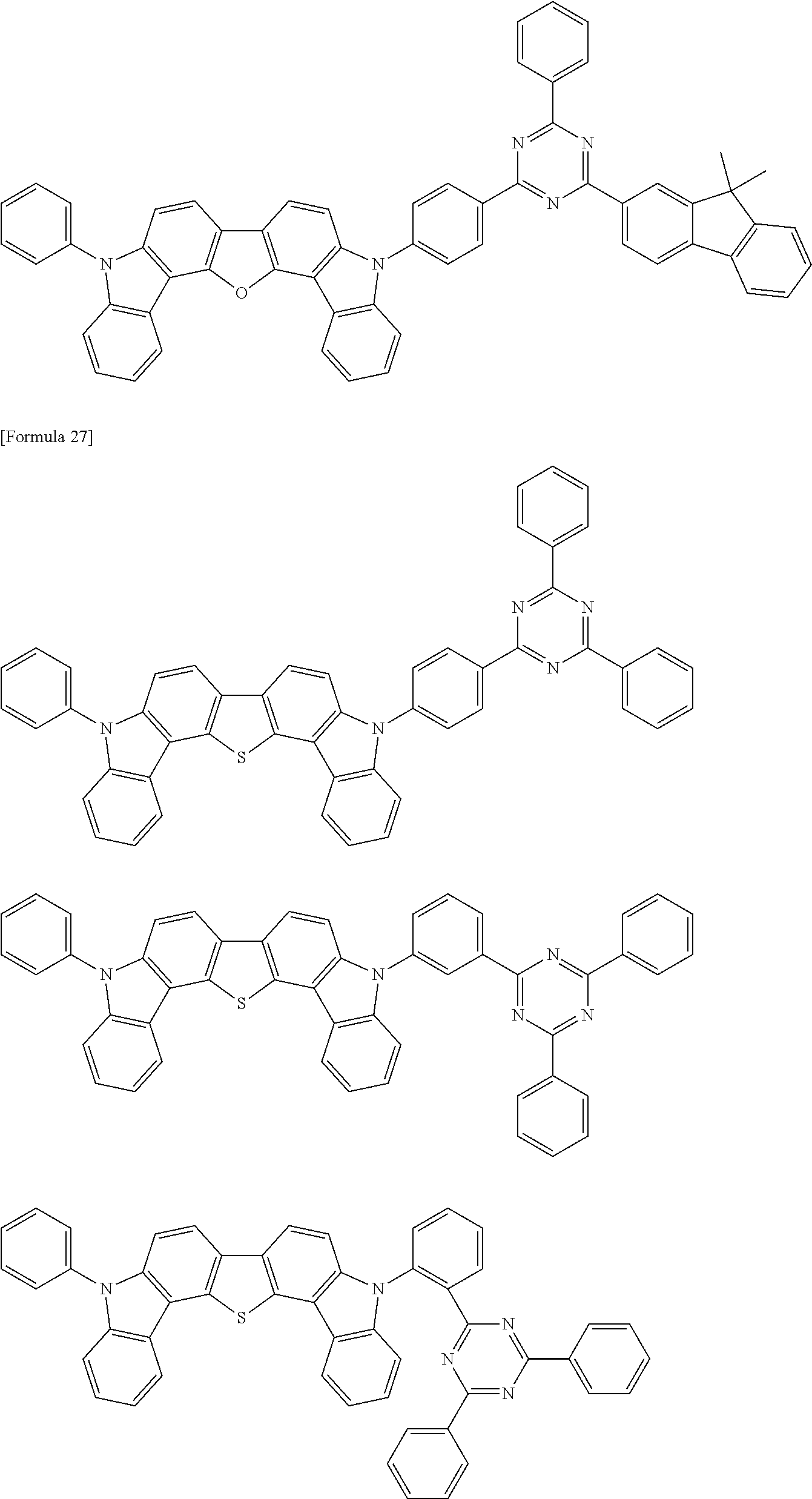


Second Compound
The second compound of the exemplary embodiment has a singlet energy larger than that of the first compound.
In the exemplary embodiment, the second compound preferably has at least one of a partial structure represented by a formula (21) below and a partial structure represented by a formula (22) below in one molecule.

In the formula (21), Y21 to Y26 are each independently a nitrogen atom or a carbon atom bonded to another atom in the molecule of the second compound.
It should be noted that at least one of Y21 to Y26 is a carbon atom bonded to another atom in the molecule of the second compound.
In the formula (22), Y31 to Y38 are each independently a nitrogen atom or a carbon atom bonded to another atom in the molecule of the second compound.
It should be noted that at least one of Y31, to Y38 is a carbon atom bonded to another atom in the molecule of the second compound.
X2 is a nitrogen atom, an oxygen atom or a sulfur atom.
In the exemplary embodiment, the partial structure represented by the formula (21) is preferably in a form of at least one group selected from the group consisting of groups represented by formulae (23) and (24) below and preferably contained in the second compound.
For the second compound, bonding positions are preferably both situated in meta positions as shown in the formulae (23) and (24) to keep an energy gap T77K(M3) at 77 [K] high.

In the above formulae (23) to (24),
-
- Y21, Y22, Y24 and Y26 are each independently a nitrogen atom or CR21.
R21 is a hydrogen atom or a substituent. When R21 is a substituent, the substituent is selected from the group consisting of a substituted or unsubstituted aromatic hydrocarbon group having 6 to 30 ring carbon atoms, a substituted or unsubstituted heterocyclic group having 5 to 30 ring atoms, a substituted or unsubstituted alkyl group having 1 to 30 carbon atoms, a substituted or unsubstituted fluoroalkyl group having 1 to 30 carbon atoms, a substituted or unsubstituted cycloalkyl group having 3 to 30 carbon atoms, a substituted or unsubstituted aralkyl group having 7 to 30 carbon atoms, a substituted silyl group, a substituted germanium group, a substituted phosphine oxide group, a halogen atom, a cyano group, a nitro group, and a carboxy group. However, the substituted or unsubstituted aromatic hydrocarbon group having 6 to 30 ring carbon atoms in R21 is a non-fused ring.
Wavy lines in the formulae (23) and (24) each show a bonding position with another atom or another structure in the molecule of the second compound.
In the exemplary embodiment, Y21, Y22, Y24 and Y26 in the formula (23) are preferably each independently CR21. A plurality of R21 may be the same or different.
In the exemplary embodiment, Y22, Y24 and Y26 in the formula (24) are preferably each independently CR21. A plurality of R21 are optionally mutually the same or different.
In the exemplary embodiment, the substituted germanium group is preferably represented by —Ge(R101)3. R101 is each independently a substituent. The substituent R101 is preferably a substituted or unsubstituted alkyl group having 1 to 30 carbon atoms or a substituted or unsubstituted aromatic hydrocarbon group having 6 to 30 ring carbon atoms. A plurality of R101 are optionally mutually the same or different.
In the exemplary embodiment, the partial structure represented by the formula (22) is preferably in a form of at least one group selected from the group consisting of a group represented by a formula (25) below, a group represented by a formula (26) below, a group represented by a formula (27) below, a group represented by a formula (28) below, a group represented by a formula (29) below and a group represented by a formula (20a) below, and preferably contained in the second compound.


In the above formulae (25) to (29) and (20a), Y31, Y32, Y33, Y34, Y35, Y36, Y37 and Y38 are each independently a nitrogen atom or CR22; in which R22 is a hydrogen atom or a substituent. When R22 is a substituent, the substituent is selected from the group consisting of a substituted or unsubstituted aromatic hydrocarbon group having 6 to 30 ring carbon atoms, a substituted or unsubstituted heterocyclic group having 5 to 30 ring atoms, a substituted or unsubstituted alkyl group having 1 to 30 carbon atoms, a substituted or unsubstituted fluoroalkyl group having 1 to 30 carbon atoms, a substituted or unsubstituted cycloalkyl group having 3 to 30 carbon atoms, a substituted or unsubstituted aralkyl group having 7 to 30 carbon atoms, a substituted silyl group, a substituted germanium group, a substituted phosphine oxide group, a halogen atom, a cyano group, a nitro group, and a carboxy group. However, the substituted or unsubstituted aromatic hydrocarbon group having 6 to 30 ring carbon atoms in R22 is a non-fused ring.
X2 in the formulae (25) and (26) is a nitrogen atom.
X2 in the formulae (27) to (29) and (20a) is NR23, an oxygen atom or a sulfur atom, in which R23 is a substituent selected from the group consisting of a substituted or unsubstituted aromatic hydrocarbon group having 6 to 30 ring carbon atoms, a substituted or unsubstituted heterocyclic group having 5 to 30 ring atoms, a substituted or unsubstituted alkyl group having 1 to 30 carbon atoms, a substituted or unsubstituted fluoroalkyl group having 1 to 30 carbon atoms, a substituted or unsubstituted cycloalkyl group having 3 to 30 carbon atoms, a substituted or unsubstituted aralkyl group having 7 to 30 carbon atoms, a substituted silyl group, a substituted germanium group, a substituted phosphine oxide group, a fluorine atom, a cyano group, a nitro group, and a carboxy group. However, the substituted or unsubstituted aromatic hydrocarbon group having 6 to 30 ring carbon atoms in R2 is a non-fused ring.
Wavy lines in the formulae (25) to (29) and (20a) each show a bonding position with another atom or another structure in the molecule of the second compound.
In the exemplary embodiment: Y31 to Y38 in the formula (25) are preferably each independently CR22; Y31 to Y35 and Y37 in the formula (26) and the formula (27) are preferably each independently CR22; Y31, Y32, Y34, Y35, Y37 and Y38 in the formula (28) are preferably each independently CR22; Y32 to Y38 in the formula (29) are preferably each independently CR22; Y32 to Y37 in the formula (20a) are preferably each independently CR22; and a plurality of R22 are optionally mutually the same or different.
In the exemplary embodiment, the second compound preferably contains a group represented by a formula (20A) below.
For the second compound, bonding positions are preferably situated as shown in the formula (20A) to keep the energy gap T77K at 77 [K] high.

In the formula (20A) Y21, Y22, Y24 and Y26 are each independently a nitrogen atom or CR21; Y31, Y32 and Y34 to Y38 are each independently a nitrogen atom, CR22 or a carbon atom bonded to another atom in the molecule of the second compound.
R21 and R22 are each independently a hydrogen atom or a substituent. When R21 and R22 are substituents, the substituents are each selected from the group consisting of a substituted or unsubstituted aromatic hydrocarbon group having 6 to 30 ring carbon atoms, a substituted or unsubstituted heterocyclic group having 5 to 30 ring atoms, a substituted or unsubstituted alkyl group having 1 to 30 carbon atoms, a substituted or unsubstituted fluoroalkyl group having 1 to 30 carbon atoms, a substituted or unsubstituted cycloalky group having 3 to 30 carbon atoms, a substituted or unsubstituted arakyl group having 7 to 30 carbon atoms, a substituted silyl group, a substituted germanium group, a substituted phosphine oxide group, a fluorine atom, a cyano group, a nitro group, and a carboxy group. However, the substituted or unsubstituted aromatic hydrocarbon group having 6 to 30 ring carbon atoms in R21 and R22 is a non-fused ring.
X2 is NR23, an oxygen atom or a sulfur atom; in which R23 is a substituent selected from the group consisting of a substituted or unsubstituted aromatic hydrocarbon group having 6 to 30 ring carbon atoms, a substituted or unsubstituted heterocyclic group having 5 to 30 ring atoms, a substituted or unsubstituted alkyl group having 1 to 30 carbon atoms, a substituted or unsubstituted fluoroalkyl group having 1 to 30 carbon atoms, a substituted or unsubstituted cycloalkyl group having 3 to 30 carbon atoms, a substituted or unsubstituted aralkyl group having 7 to 30 carbon atoms, a substituted silyl group, a substituted germanium group, a substituted phosphine oxide group, a fluorine atom, a cyano group, a nitro group, and a carboxy group. However, the substituted or unsubstituted aromatic hydrocarbon group having 6 to 30 ring carbon atoms in R23 is a non-fused ring.
Y22 and Y34 are optionally cross-linked via an oxygen atom, sulfur atom or CR51R52.
Y24 and Y32 are optionally cross-linked via an oxygen atom, sulfur atom or CR53R54.
R51 to R54 each independently represent the same as R23 being the substituent.
In the formula (20A), a wavy line shows a bonding position with another atom or another structure in the molecule of the second compound.
For instance, when Y22 and Y34 are cross-linked via an oxygen atom, sulfur atom or CR51R52 in the formula (20A), the formula (20A) is represented by a formula (20A-1) below.

It should be noted that Z21 is an oxygen atom, sulfur atom or CR51R52 in the formula (20A-1). In the formula (20A-1), X2, Y21, Y24, Y26, Y31, Y32 and Y35 to Y38 respectively represent the same as X2, Y21, Y24, Y26, Y31, Y32 and Y35 to Y38 in the formula (20A).
In the exemplary embodiment, the second compound also preferably contains a group represented by a formula (20B) below.
For the second compound, bonding positions are preferably situated as shown in the formula (20B) to keep the energy gap T77K at 77 [K] high.

In the formula (20B): Y21, Y22, Y24 and Y26 are each independently a nitrogen atom or CR21, Y31, Y32, Y34, Y35, Y37 and Y38 are each independently a nitrogen atom or CR22, Y41 to Y45, Y47 and Y48 are each independently a nitrogen atom, CR24 or a carbon atom bonded to another atom in the molecule of the second compound.
R21, R22 and R24 are each independently a hydrogen atom or a substituent. When R21, R22 and R24 are substituents, the substituents are each selected from the group consisting of a substituted or unsubstituted aromatic hydrocarbon group having 6 to 30 ring carbon atoms, a substituted or unsubstituted heterocyclic group having 5 to 30 ring atoms, a substituted or unsubstituted alkyl group having 1 to 30 carbon atoms, a substituted or unsubstituted fluoroalkyl group having 1 to 30 carbon atoms, a substituted or unsubstituted cycloalkyl group having 3 to 30 carbon atoms, a substituted or unsubstituted aralkyl group having 7 to 30 carbon atoms, a substituted silyl group, a substituted germanium group, a substituted phosphine oxide group, a fluorine atom, a cyano group, a nitro group, and a carboxy group. However, the substituted or unsubstituted aromatic hydrocarbon group having 6 to 30 ring carbon atoms in R21, R22 and R24 is a non-fused ring.
X2 is NR23, an oxygen atom or a sulfur atom.
X3 is NR23, an oxygen atom or a sulfur atom.
R23 and R25 are each independently selected from the group consisting of a substituted or unsubstituted aromatic hydrocarbon group having 6 to 30 ring carbon atoms, a substituted or unsubstituted heterocyclic group having 5 to 30 ring atoms, a substituted or unsubstituted alkyl group having 1 to 30 carbon atoms, a substituted or unsubstituted fluoroalkyl group having 1 to 30 carbon atoms, a substituted or unsubstituted cycloalkyl group having 3 to 30 carbon atoms, a substituted or unsubstituted aralkyl group having 7 to 30 carbon atoms, a substituted siyl group, a substituted germanium group, a substituted phosphine oxide group, a fluorine atom, a cyano group, a nitro group, and a carboxy group. However, the substituted or unsubstituted aromatic hydrocarbon group having 6 to 30 ring carbon atoms in R23 and R25 is a non-fused ring.
Y22 and Y34 are optionally cross-linked via an oxygen atom, sulfur atom or CR51R52.
Y24 and Y32 are optionally cross-linked via an oxygen atom, sulfur atom or CR53R54.
R51 to R54 each independently represent the same as R23 and R25 being the substituent.
In the formula (20B), a wavy line shows a bonding position with another atom or another structure in the molecule of the second compound.
For instance, when Y22 and Y34 are cross-linked via an oxygen atom, sulfur atom or CR51R52 in the formula (20B), the formula (20B) is represented by a formula (20A-1) below.

It should be noted that Z22 is an oxygen atom, sulfur atom or CR51R52 in the formula (20B-1). In the formula (20B-1), X2, X3, Y21, Y24, Y26, Y31, Y32, Y35, Y37, Y38, Y41 to Y45, Y47 and Y48 respectively represent the same as X2, X3, Y21, Y24, Y26, Y31, Y32, Y35, Y37, Y38, Y41 to Y45, Y47 and Y48 in the formula (20B).
In the exemplary embodiment, the second compound also preferably contains a group represented by a formula (20C) below.
For the second compound, bonding positions are preferably situated as shown in the formula (20C) to keep the energy gap T77K at 77 [K] high.

In the formula (20C): Y21, Y22, Y24 and Y26 are each independently a nitrogen atom or CR21; and Y51, Y53, Y54 and Y55 are each independently a nitrogen atom or CR26.
R21 and R26 are each independently a hydrogen atom or a substituent. When R21 and R26 are substituents, the substituents are each selected from the group consisting of a substituted or unsubstituted aromatic hydrocarbon group having 6 to 30 ring carbon atoms, a substituted or unsubstituted heterocyclic group having 5 to 30 ring atoms, a substituted or unsubstituted alkyl group having 1 to 30 carbon atoms, a substituted or unsubstituted fluoroalkyl group having 1 to 30 carbon atoms, a substituted or unsubstituted cycloakyl group having 3 to 30 carbon atoms, a substituted or unsubstituted aralkyl group having 7 to 30 carbon atoms, a substituted silyl group, a substituted germanium group, a substituted phosphine oxide group, a fluorine atom, a cyano group, a nitro group, and a carboxy group. However, the substituted or unsubstituted aromatic hydrocarbon group having 6 to 30 ring carbon atoms in R21 and R26 is a non-fused ring.
Y22 and Y51, are optionally cross-linked via an oxygen atom, sulfur atom or CR55R56.
Y24 and Y55 are optionally cross-linked via an oxygen atom, sulfur atom or CR57R55.
R55 to R58 are each independently a substituent selected from the group consisting of a substituted or unsubstituted aromatic hydrocarbon group having 6 to 30 ring carbon atoms, a substituted or unsubstituted heterocyclic group having 5 to 30 ring atoms, a substituted or unsubstituted alkyl group having 1 to 30 carbon atoms, a substituted or unsubstituted fluoroalkyl group having 1 to 30 carbon atoms, a substituted or unsubstituted cycloalkyl group having 3 to 30 carbon atoms, a substituted or unsubstituted aralkyl group having 7 to 30 carbon atoms, a substituted silyl group, a substituted germanium group, a substituted phosphine oxide group, a fluorine atom, a cyano group, a nitro group, and a carboxy group. However, the substituted or unsubstituted aromatic hydrocarbon group having 6 to 30 ring carbon atoms in R55 to R58 is a non-fused ring.
In the formula (20C), a wavy line shows a bonding position with another atom or another structure in the molecule of the second compound.
For instance, when Y22 and Y51 are cross-linked via an oxygen atom, sulfur atom or CR55R56 in the formula (20C), the formula (20C) is represented by a formula (20C-1) below.

It should be noted that Z23 is an oxygen atom, sulfur atom or CR55R56 in the formula (20C-1). In the formula (20C-1), Y21, Y24, Y26 and Y53 to Y55 represent the same as Y21, Y24, Y26 and Y53 to Y55 in the formula (20C).
In the exemplary embodiment, the second compound also preferably contains a group represented by a formula (20D) below.
For the second compound, bonding positions are preferably situated as shown in the formula (20D) to keep the energy gap T77K at 77 [K] high.

In the formula (20D): Y21, Y22, Y24 and Y26 are each independently a nitrogen atom or CR21; Y51, Y53, Y54 and Y55 are each independently a nitrogen atom or CR26; and Y31 to Y35, Y37 and Y38 are each independently a nitrogen atom, CR22 or a carbon atom bonded to another atom in the molecule of the second compound.
R21, R22 and R26 are each independently a hydrogen atom or a substituent. When R21, R22 and R26 are substituents, the substituents are each selected from the group consisting of a substituted or unsubstituted aromatic hydrocarbon group having 6 to 30 ring carbon atoms, a substituted or unsubstituted heterocyclic group having 5 to 30 ring atoms, a substituted or unsubstituted alkyl group having 1 to 30 carbon atoms, a substituted or unsubstituted fluoroalkyl group having 1 to 30 carbon atoms, a substituted or unsubstituted cycloalkyl group having 3 to 30 carbon atoms, a substituted or unsubstituted aralkyl group having 7 to 30 carbon atoms, a substituted silyl group, a substituted germanium group, a substituted phosphine oxide group, a fluorine atom, a cyano group, a nitro group, and a carboxy group. However, the substituted or unsubstituted aromatic hydrocarbon group having 6 to 30 ring carbon atoms in R21, R22 and R26 is a non-fused ring.
X2 is NR23, an oxygen atom or a sulfur atom.
R23 is a substituent selected from the group consisting of a substituted or unsubstituted aromatic hydrocarbon group having 6 to 30 ring carbon atoms, a substituted or unsubstituted heterocyclic group having 5 to 30 ring atoms, a substituted or unsubstituted alkyl group having 1 to 30 carbon atoms, a substituted or unsubstituted fluoroalkyl group having 1 to 30 carbon atoms, a substituted or unsubstituted cycloalkyl group having 3 to 30 carbon atoms, a substituted or unsubstituted aralkyl group having 7 to 30 carbon atoms, a substituted silyl group, a substituted germanium group, a substituted phosphine oxide group, a fluorine atom, a cyano group, a nitro group, and a carboxy group. However, the substituted or unsubstituted aromatic hydrocarbon group having 6 to 30 ring carbon atoms in R23 is a non-fused ring.
Y22 and Y51 are optionally cross-linked via an oxygen atom, sulfur atom or CR55R56.
Y24 and Y55 are optionally cross-linked via an oxygen atom, sulfur atom or CR57R60.
Y51 and Y35 are optionally cross-linked via an oxygen atom, sulfur atom or CR61R62.
Y53 and Y35 are optionally cross-linked via an oxygen atom, sulfur atom or CR61R62.
R55 to R62 each independently represent the same as R23 being the substituent. In the formula (20D), a wavy line shows a bonding position with another atom or another structure in the molecule of the second compound.
For instance, when Y22 and Y51, are cross-linked via an oxygen atom, sulfur atom or CR55R56 in the formula (20D), the formula (20D) is represented by a formula (201D-1) below.

It should be noted that Z24 is an oxygen atom, sulfur atom or CR55R56 in the formula (20D-1). In the formula (20D-1), X2, Y21, Y24, Y26, Y31 to Y35, Y37, Y38 and Y53 to Y55 represent the same as X2, Y21, Y24, Y26, Y31 to Y35, Y37, Y38 and Y53 to Y55 in the formula (20D).
For instance, when Y1 and Y % are cross-linked via an oxygen atom, sulfur atom or CR59R60 in the formula (20D), the formula (20D) is represented by a formula (20D-2) below.

It should be noted that Z25 is an oxygen atom, sulfur atom or CR55R60 in the formula (20D-2). In the formula (20D-2), X2, Y21, Y22, Y24, Y26, Y31 to Y35, Y38 and Y53 to Y55 represent the same as X2, Y21, Y22, Y24, Y26, Y31 to Y35, Y38 and Y53 to Y55 in the formula (20D).
In the exemplary embodiment, the second compound also preferably contains a group represented by a formula (20E) below.
For the second compound, bonding positions are preferably situated as shown in the formula (20E) to keep the energy gap T77K at 77 [K] high.

In the formula (20E): Y31, Y32, Y34, Y35, Y37 and Y38 are each independently a nitrogen atom or CR22, Y41 to Y45, Y47 and Y48 are each independently a nitrogen atom, CR24 or a carbon atom bonded to another atom in the molecule of the second compound.
R22 and R24 are each independently a hydrogen atom or a substituent. When R22 and R24 are substituents, the substituents are each selected from the group consisting of a substituted or unsubstituted aromatic hydrocarbon group having 6 to 30 ring carbon atoms, a substituted or unsubstituted heterocyclic group having 5 to 30 ring atoms, a substituted or unsubstituted alkyl group having 1 to 30 carbon atoms, a substituted or unsubstituted fluoroalkyl group having 1 to 30 carbon atoms, a substituted or unsubstituted cycloalkyl group having 3 to 30 carbon atoms, a substituted or unsubstituted aralkyl group having 7 to 30 carbon atoms, a substituted silyl group, a substituted germanium group, a substituted phosphine oxide group, a fluorine atom, a cyano group, a nitro group, and a carboxy group. However, the substituted or unsubstituted aromatic hydrocarbon group having 6 to 30 ring carbon atoms in R22 and R24 is a non-fused ring.
X2 is NR23, an oxygen atom or a sulfur atom.
X3 is NR25, an oxygen atom or a sulfur atom.
R23 and R25 are each independently selected from the group consisting of a substituted or unsubstituted aromatic hydrocarbon group having 6 to 30 ring carbon atoms, a substituted or unsubstituted heterocyclic group having 5 to 30 ring atoms, a substituted or unsubstituted alkyl group having 1 to 30 carbon atoms, a substituted or unsubstituted fluoroalkyl group having 1 to 30 carbon atoms, a substituted or unsubstituted cycloalkyl group having 3 to 30 carbon atoms, a substituted or unsubstituted aralkyl group having 7 to 30 carbon atoms, a substituted silyl group, a substituted germanium group, a substituted phosphine oxide group, a fluorine atom, a cyano group, a nitro group, and a carboxy group. However, the substituted or unsubstituted aromatic hydrocarbon group having 6 to 30 ring carbon atoms in R23 and R25 is a non-fused ring.
In the formula (20E), a wavy line shows a bonding position with another atom or another structure in the molecule of the second compound.
In the exemplary embodiment, the second compound may contain at least one of a group represented by a formula (20F) below, a group represented by a formula (20G) below and a group represented by a formula (20H) below.


In the formulae (20F), (20G) and (20H): Y21, Y22, Y24, Y26, Y31 to Y38, Y41 to Y48, Y61 to Y65, Y67 and Y68 are each independently a nitrogen atom, CR27 or a carbon atom bonded to another atom in the molecule of the second compound.
R27 is each independently a hydrogen atom or a substituent. When R27 is a substituent, the substituent is selected from the group consisting of a substituted or unsubstituted aromatic hydrocarbon group having 6 to 30 ring carbon atoms, a substituted or unsubstituted heterocyclic group having 5 to 30 ring atoms, a substituted or unsubstituted alkyl group having 1 to 30 carbon atoms, a substituted or unsubstituted fluoroalkyl group having 1 to 30 carbon atoms, a substituted or unsubstituted cycloalkyl group having 3 to 30 carbon atoms, a substituted or unsubstituted aralkyl group having 7 to 30 carbon atoms, a substituted sily group, a substituted germanium group, a substituted phosphine oxide group, a fluorine atom, a cyano group, a nitro group, and a carboxy group. However, the substituted or unsubstituted aromatic hydrocarbon group having 6 to 30 ring carbon atoms in R27 is a non-fused ring.
X2 and X4 are each independently NR28, an oxygen atom or a sulfur atom, in which R28 is each independently selected from the group consisting of a substituted or unsubstituted aromatic hydrocarbon group having 6 to 30 ring carbon atoms, a substituted or unsubstituted heterocyclic group having 5 to 30 ring atoms, a substituted or unsubstituted alkyl group having 1 to 30 carbon atoms, a substituted or unsubstituted fluoroalkyl group having 1 to 30 carbon atoms, a substituted or unsubstituted cycloolkyl group having 3 to 30 carbon atoms, a substituted or unsubstituted aralkyl group having 7 to 30 carbon atoms, a substituted silyl group, a substituted germanium group, a substituted phosphine oxide group, a fluorine atom, a cyano group, a nitro group, and a carboxy group. However, the substituted or unsubstituted aromatic hydrocarbon group having 6 to 30 ring carbon atoms in R28 is a non-fused ring.
Wavy lines in the formulae (20F), (20G) and (20H) each show a bonding position with another atom or another structure in the molecule of the second compound.
In the exemplary embodiment, X2 is preferably an oxygen atom or a sulfur atom, more preferably an oxygen atom.
X3 is preferably an oxygen atom or a sulfur atom, more preferably an oxygen atom.
X4 is preferably an oxygen atom or a sulfur atom, more preferably an oxygen atom.
Moreover, X2 and X3 are preferably an oxygen atom.
Moreover, X2 and X4 are preferably an oxygen atom.
In the exemplary embodiment, R21, R22, R24, R26 and R27 are each independently a hydrogen atom or a substituent. The substituent in R21, R22, R24, R26 and R27 is preferably selected from the group consisting of a fluorine atom, a cyano group, a substituted or unsubstituted alkyl group having 1 to 30 carbon atoms, a substituted or unsubstituted aromatic hydrocarbon group having 6 to 30 ring carbon atoms, and substituted or unsubstituted heterocyclic group having 5 to 30 ring atoms. R21, R22, R24, R26 and R27 are more preferably a hydrogen atom, a cyano group, a substituted or unsubstituted aromatic hydrocarbon group having 6 to 30 ring carbon atoms, or a substituted or unsubstituted aromatic heterocyclic group having 5 to 30 ring atoms. However, the substituted or unsubstituted aromatic hydrocarbon group having 6 to 30 ring carbon atoms in R21, R22, R24, R26 and R27 is a non-fused ring.
In the exemplary embodiment, R23, R25 and R28 are preferably each independently a substituent selected from the group consisting of a substituted or unsubstituted aromatic hydrocarbon group having 6 to 30 ring carbon atoms and a substituted or unsubstituted heterocyclic group having 5 to 30 ring atoms, more preferably a substituent selected from the group consisting of a substituted or unsubstituted aromatic hydrocarbon group having 6 to 20 ring carbon atoms and a substituted or unsubstituted heterocyclic group having 5 to 20 ring atoms. However, the substituted or unsubstituted aromatic hydrocarbon group having 6 to 30 ring carbon atoms in R23, R25 and R28 is a non-fused ring.
In the exemplary embodiment, R51 to R62 are preferably each independently a substituent selected from the group consisting of a substituted or unsubstituted alkyl group having 1 to 30 carbon atoms, a substituted or unsubstituted aromatic hydrocarbon group having 6 to 30 ring carbon atoms, and a substituted or unsubstituted heterocyclic group having 5 to 30 ring atoms, more preferably a substituent selected from the group consisting of a substituted or unsubstituted aromatic hydrocarbon group having 6 to 20 ring carbon atoms and a substituted or unsubstituted heterocyclic group having 5 to 20 ring atoms. However, the substituted or unsubstituted aromatic hydrocarbon group having 6 to 30 ring carbon atoms in R51 to R62 is a non-fused ring.
Method of Preparing Second Compound
The second compound can be prepared by a method described in International Publication Nos. WO2012/153780A1 and WO2013-038650A1.
Specific examples of the substituent for the second compound of the exemplary embodiment are shown below, but the invention is not limited thereto.
Specific examples of the aromatic hydrocarbon group (aryl group) include a phenyl group, tolyl group, xylyl group, naphthyl group, phenanthryl group, pyrenyl group, chrysenyl group, benzo[c]phenanthryl group, benzo[g]chrysenyl group, benzoanthryl group, triphenylenyl group, fluorenyl group, 9,9-dimethylfluorenyl group, benzofluorenyl group, dibenzofluorenyl group, biphenyl group, terphenyl group, quarterphenyl group and fluoranthenyl group, among which a phenyl group, biphenyl group, terphenyl group, quarterphenyl group, naphthyl group, triphenylenyl group and fluorenyl group may be preferable.
Specific examples of the substituted aromatic hydrocarbon group include a tolyl group, xylyl group and 9,9-dimethylfluorenyl group.
As is understood from the specific examples, the aryl group includes both fused aryl group and non-fused aryl group.
Preferable examples of the aromatic hydrocarbon group include a phenyl group, biphenyl group, terphenyl group, quarterphenyl group, naphthyl group, triphenylenyl group and fluorenyl group.
Specific examples of the aromatic heterocyclic group (heteroaryl group, heteroaromatic ring group and heterocyclic group) include a pyrrolyl group, pyrazolyl group, pyrazinyl group, pyrimidinyl group, pyridazynyl group, pyridyl group, triazinyl group, indolyl group, isoindolyl group, imidazolyl group, benimidazolyl group, indazolyl group, imidazo[1,2-a]pyridinyl group, furyl group, benzofuranyl group, isobenzofuranyl group, dibenzofuranyl group, azadibenzofuranyl group, thiophenyl group, benzothiophenyl group, dibenzothiophenyl group, azadibenxothiophenyl group, quinolyl group, isoquinolyl group, quinoxalinyl group, quinazolinyl group, naphthyridinyl group, carbazolyl group, azacarbazolyl group, phenanthridinyl group, acridinyl group, phenathrolinyl group, phenazinyl group, phenothiazinyl group, phenoxazinyl group, oxazolyl group, oxadiazolyl group, furazanyl group, benzoxazolyl group, thienyl group, thiazolyl group, thiadiazolyl group, benzothiazolyl group, triazolyl group and tetrazolyl group, among which a dibenzofuranyl group, dibenzothiophenyl group, carbazolyl group, pyridyl group, pyrimidinyl group, triazinyl group, azadibenzofuranyl group and azadibenzothiophenyl group may be preferable.
The aromatic heterocyclic group is preferably any one of a dibenzofuranyl group, dibenzothiophenyl group, carbazolyl group, pyridyl group, pyrimidinyl group, triazinyl group, azadibenzofuranyl group and azadibenzothiophenyl group, and further preferably any one of a dibenzofuranyl group, dibenzothiophenyl group, azadibenzofuranyl group and azadibenzothiophenyl group.
In the second compound of the exemplary embodiment, the substituted silyl group is also preferably a substituted or unsubstituted trialkylsilyl group, a substituted or unsubstituted arylalkylsilyl group, or a substituted or unsubstituted triarylsilyl group.
Specific examples of the substituted or unsubstituted trialkylsilyl group include trimethylsilyl group and triethylsilyl group.
Specific examples of the substituted or unsubstituted arylalkylsilyl group include diphenylmethylsilyl group, ditoylmethylsilyl group, and phenyldimethylsilyl group.
Specific examples of the substituted or unsubstituted triarylsilyl group include triphenylsilyl group and tritolylsilyl group.
In the second compound of the exemplary embodiment, the substituted phosphine oxide is also preferably a substituted or unsubstituted diaryl phosphine oxide group.
Specific examples of the substituted or unsubstituted diaryl phosphine oxide group include a diphenyl phosphine oxide group and ditolyl phosphine oxide group.
Examples of the second compound according to the exemplary embodiment are shown below. It should be noted that the second compound according to the invention is not limited to these specific examples.


Third Compound
A third compound in the exemplary embodiment is a fluorescent compound and an emission color and emission wavelength thereof are not particularly limited.
For instance, the third compound preferably emits red, yellow, green or blue fluorescence, more preferably red, yellow or green fluorescence, further preferably yellow or green fluorescence, particularly preferably green fluorescence.
Moreover, for instance, the third compound preferably emits fluorescence with a main peak wavelength from 500 nm to 600 nm, more preferably fluorescence with a main peak wavelength from 510 nm to 550 nm. On the other hand, the third compound also preferably emits light having a main peak wavelength exceeding 600 nm.
The main peak wavelength means a peak wavelength of luminescence spectrum exhibiting a maximum luminous intensity among luminous spectra measured in a toluene solution in which a measurement target compound is dissolved at a concentration from 10−5 mol/l to 10−6 mol/l.
The third compound preferably exhibits a high fluorescence quantum efficiency.
A fluorescent material is usable as the third compound in the exemplary embodiment. Specific examples of the fluorescent material include a bisarylaminonaphthalene derivative, aryl-substituted naphthalene derivative, bisarylaminoanthracene derivative, aryl-substituted anthracene derivative, bisarylaminopyrene derivative, aryl-substituted pyrene derivative, bisarylaminochrysene derivative, aryl-substituted chrysene derivative, bisarylaminofluoranthene derivative, aryl-substituted fluoranthene derivative, indenoperylene derivative, pyrromethene boron complex compound, compound having a pyrromethene skeleton, metal comlex of a compound having a pyrromethene skeleton, diketopyrolopyrrol derivative, perylene derivative, arylaminofluorene derivative, aryl-substituted fluorene derivative, arylaminobenofluorene derivative, aryl-substituted benzofluorene derivative, arylamino indenofluorene derivative, and aryl-substituted indenofluorene derivative.
In the exemplary embodiment, the third compound is preferably a compound having at least one of a partial structure represented by a formula (3) below in one molecule. When the third compound has a plurality of partial structures represented by the formula (3) below, the plurality of partial structures may be mutually the same or different.

In the formula (3), X3 is a substituted or unsubstituted fused aromatic hydrocarbon group having 10 to 40 ring carbon atoms;
Ar11 and Ar12 are each independently a group selected from the group consisting of a substituted or unsubstituted aromatic hydrocarbon group having 6 to 40 ring carbon atoms and a substituted or unsubstituted heterocyclic group having 5 to 30 ring atoms.
L11, L12 and L13 are each independently a single bond or a linking group. When L11, L12 and L13 are linking groups, the linking groups are selected from the group consisting of a substituted or unsubstituted aromatic hydrocarbon group having 6 to 30 ring carbon atoms and a substituted or unsubstituted heterocyclic group having 5 to 30 ring atoms.
p is an integer of 1 to 4.
When L11 and L13 are single bonds, Ar11 and X3 may be mutually bonded to form a ring. When L12 and L13 are single bonds. Ar12 and X3 may be mutually bonded to form a ring.
In the formula (3), X3 is preferably a residue of a fused aromatic hydrocarbon ring selected from the group consisiting of naphthalene, phenanthrene, fluoranthene, anthracene, pyrene, perylene, coronene, chrysene, picene, diphenylanthracene, fluorene, triphenylene, rubicene, benzanthracene, phenylanthracene, bisanthracene, dianthrylbenzene, dibenzoanthracene, benzofluorene, indenofluorene, and benzindenofluorene.
Particularly, when X3 is a residue of anthracene, the second compound is preferably 9,10-substituted anthracene or 2,6-substituted anthracene. When X3 is a residue of pyrene, the second compound is preferably 1,6-substituted pyrene or 3,8-substituted pyrene. When X3 is a residue of chrysene, the second compound is preferably 6,12-substituted chrysene.
In the first exemplary embodiment, the partial structure represented by the formula (3) is preferably a group represented by a formula (3A) below.

In the formula (3A), X3, Ar11, Ar12, L11, L12, L13 and p each independently represent the same as X3, Ar11, Ar12, L11, L12, L13 and p in the formula (3). In the formula (3A), a wavy line shows a bonding position with another atom or another structure in the molecule of the second compound.
In the exemplary embodiment, the third compound is preferably a compound represented by a formula (30) below.

In the formula (30), a is an integer of 0 or 1.
When a is 0, L2 is directly bonded to Ar2 and at least two of Ar1, Ar2, R121, R122, R123, R124, R125, R126, R127 and R128 are groups represented by a formula (31) below.
When a is 1, at least two of Ar1, Ar2, R121, R122, R123, R124, R125, R126, R127, R128, R131, R132, R133, R134, R135, R136, R137 and R138 are groups represented by a formula (31) below.
The rest of Ar1, Ar2, R121, R122, R123, R124, R125, R126, R127, R128, R131, R132, R133, R134, R135, R136, R137 and R138 except for the groups represented by the formula (31) below each independently is a hydrogen atom or a substituent. When Ar1, Ar2, R121, R122, R123, R124, R125, R126, R127, R128, R131, R132, R133, R134, R135, R136, R137 and R138 are substituents, the substituents are each independently selected from the group consisting of a halogen atom, a cyano group, a substituted or unsubstituted aromatic hydrocarbon group having 6 to 30 ring carbon atoms, a substituted or unsubstituted heterocyclic group having 5 to 30 ring atoms, a substituted or unsubstituted alkyl group having 1 to 30 carbon atoms, a substituted or unsubstituted alkenyl group having 2 to 30 carbon atoms, a substituted or unsubstituted alkynyl group having 2 to 30 carbon atoms, a substituted silyl group, a substituted or unsubstituted trifluoroalkyl group having 1 to 20 carbon atoms, a substituted or unsubstituted alkoxy group having 1 to 30 carbon atoms, a substituted or unsubstituted aralkyl group having 6 to 30 ring carbon atoms, and a substituted or unsubstituted aryloxy group having 6 to 30 ring atoms.
L1 and L2 are each independently a single bond or a linking group. When L1 and L2 are linking groups, the linking groups are each independently selected from the group consisting of a substituted or unsubstituted aromatic hydrocarbon group having 6 to 30 ring carbon atoms and a substituted or unsubstituted heterocyclic group having 5 to 30 ring atoms.
When two or more of R121 to R128 and R131 to R138 are substituents, the substituents may be mutually bonded to form a ring.

In the formula (31), L11, L12 and L13 are each independently a single bond or a linking group. When L11, L12 and L13 are linking groups, the linking groups are selected from the group consisting of a substituted or unsubstituted aromatic hydrocarbon group having 6 to 30 ring carbon atoms and a substituted or unsubstituted heterocyclic group having 5 to 30 ring atoms.
Ar11 and Ar12 are each independently a group selected from the group consisting of a substituted or unsubstituted aromatic hydrocarbon group having 6 to 30 ring carbon atoms and a substituted or unsubstituted heterocyclic group having 5 to 30 ring atoms.
In the formula (30), it is preferable that a is 0 and Ar1 and Ar2 are the groups represented by the formula (31).
In the formula (30), it is also preferable that a is 0 and R122 and R126 are the groups represented by the formula (31).
In the formula (30), it is also preferable that a is 1 and Ar1 and Ar2 are the groups represented by the formula (31).
In the formula (30), the substituents Ar1, Ar2, R121 to R128 and R131 to R138 are preferably selected from the group consisting of a substituted or unsubstituted aromatic hydrocarbon group having 6 to 30 ring carbon atoms, a substituted or unsubstituted heterocyclic group having 5 to 30 ring atoms, a substituted or unsubstituted alkyl group having 1 to 30 carbon atoms, a substituted silyl group, cyano group, and a substituted or unsubstituted trifluoroalkyl group having 1 to 20 carbon atoms.
Method of Preparing Third Compound
The third compound can be prepared by methods disclosed in International Publication Nos. WO2004/092111A1, WO2011/096506A1 and the like.
Specific examples of the third compound of the exemplary embodiment are shown below. It should be noted that the third compound according to the invention is not limited to these specific examples.


Relationship between First Compound, Second Compound and Third Compound in Emitting Layer
In the exemplary embodiment, the second compound is inferred to function as a dispersant that suppresses molecular association of the first compound of the exemplary embodiment with another in the emitting layer.
The first compound of the exemplary embodiment is a thermally activated delayed fluorescent material, and thus is likely to undergo molecular association. An excitation energy of a molecular assembly (i.e., singlet energy and triplet energy) is small as compared with an excitation energy of a monomer. For this reason, when a concentration of the first compound is high in the thin film, molecular association occurs. Accordingly, when a fluorescent material, particularly, a green-to-blue fluorescent material is used, it becomes difficult to efficiently transfer the excitation energy from thermally activated delayed fluorescent material.
Since the singlet energy of the second compound is larger than that of the first compound, the excited second compound is unstable as compared with the first and third compounds. Accordingly, the second compound preferably has no influence on generation of excitons and carrier transport in the emitting layer. For a typical organic EL device, such a second compound is a unique material in view of criteria for selecting a material to be contained in the emitting layer. While the emitting layer of a typical florescent organic EL device selectively contains a material with high electrical and optical functions, the emitting layer of the exemplary embodiment contains the second compound that has no influence on generation of excitons and carrier transport.
In the exemplary embodiment, a singlet energy S(M1) of the first compound is preferably larger than a singlet energy S(M3) of the third compound.
In other words, a relationship of S(M3)<S(M)<S(M2) is preferably satisfied.
In the exemplary embodiment, it is preferable that an energy gap T77K(M1) at 77 [K] of the first compound is larger than an energy gap T77K(M3) at 77 [K] of the third compound, and an energy gap T77K(M2) at 77 [K] of the second compound is larger than the energy gap T77K(M1) at 77 [K] of the first compound.
In other words, a relationship of T77K (M3)<T77K(M1)<T77K(M2) is preferably satisfied.
In the exemplary embodiment, the energy gap T77K(M2) at 77 [K] of the second compound is preferably 2.9 eV or more. When the second compound has the energy gap T77K(M2) in the above range, the second compound is unlikely to affect generation of excitons and carrier transport in the emitting layer.
TADF Mechanism
In the organic EL device of the exemplary embodiment, the first compound is preferably a compound having a small ΔST(M1) so that inverse intersystem crossing from the triplet energy level of the first compound to the singlet energy level thereof is easily caused by a heat energy given from the outside. An energy state conversion mechanism to perform spin exchange from the triplet state of electrically excited excitons within the organic EL device to the singlet state by inverse intersystem crossing is referred to as TADF Mechanism.
As shown in FIG. 4 , when a compound having a small ΔST(M1) is used as the first compound, inverse intersystem crossing from the lowest triplet state T1(M1) to the lowest singlet state S1(M1) can be caused by a heat energy. Consequently, Förster energy transfer from the lowest singlet state S1(M1) of the first compound to the lowest singlet state S1(M3) of the third compound is caused. Consequently, fluorescence from the lowest singlet state S1(M3) of the third compound can be observed. It is inferred that the internal quantum efficiency can be theoretically raised up to 100% also by using delayed fluorescence by the TADF mechanism.
When the organic EL device 1 of the exemplary embodiment emits light, it is preferable that the third compound in the emitting layer 5 mainly emits light.
Film Thickness of Emitting Layer
A film thickness of the emitting layer 5 of the organic EL device of the exemplary embodiment is preferably in a range from 5 nm to 50 nm, more preferably in a range from 7 nm to 50 nm, and further preferably in a range from 10 nm to 50 nm. The thickness of less than 5 nm may cause difficulty in forming the emitting layer 5 and in controlling chromaticity, while the thickness of more than 50 nm may raise drive voltage.
Content Ratio of Compounds in Emitting Layer
In the emitting layer 5 of the organic EL device of the exemplary embodiment, it is preferable that the content ratio of the first compound is in a range from 10 mass % to 80 mass %, the content ratio of the second compound is in a range from 10 mass % to 80 mass %, and the content ratio of the third compound is in a range from 1 mass % to 10 mass %. An upper limit of the total of the respective content ratios of the first, second and third compounds in the emitting layer 5 is 100 mass %. It should be noted that the emitting layer 5 of the exemplary embodiment may further contain another material in addition to the first, second and third compounds.
Substrate
A substrate 2 is used as a support for the organic EL device 1. For instance, glass, quartz, plastics and the like are usable for the substrate 2. A flexible substrate is also usable. The flexible substrate is a bendable substrate, which is exemplified by a plastic substrate formed of polycarbonate, polyarylate, polyethersulfone, polypropylene, polyester, polyvinyl fluoride, polyvinyl chloride, polyimide, and polyethylene naphthalate. Moreover, an inorganic vapor deposition film is also usable.
Anode
Metal, alloy, an electrically conductive compound and a mixture thereof, which have a large work function, specifically, of 4.0 eV or more, is preferably usable as the anode 3 formed on the substrate 2. Specific examples of the material for the anode include indium tin oxide (ITO), indium tin oxide containing silicon or silicon oxide, indium zinc oxide, tungsten oxide, indium oxide containing zinc oxide and graphene. In addition, gold (Au), platinum (Pt), nickel (Ni), tungsten (W), chrome (Cr), molybdenum (Mo), iron (Fe), cobalt (Co), copper (Cu), palladium (Pd), titanium (Ti), or nitrides of a metal material (e.g., titanium nitride) are usable.
The above materials are typically deposited as a film by sputtering. For instance, indium zinc oxide can be deposited as a film by sputtering using a target that is obtained by adding zinc oxide in a range from 1 mass % to 10 mass % to indium oxide. Moreover, for instance, indium oxide containing tungsten oxide and zinc oxide can be deposited as a film by sputtering using a target that is obtained by adding tungsten oxide in a range from 0.5 mass % to 5 mass % and zinc oxide in a range from 0.1 mass % to 1 mass % to indium oxide. In addition, vapor deposition, coating, ink jet printing, spin coating and the like may be used for forming a film.
Among the organic layers formed on the anode 3, a hole injecting layer 6 formed adjacent to the anode 3 is formed of a composite material that facilitates injection of holes irrespective of the work function of the anode 3. Accordingly, a material usable as an electrode material (e.g., metal, alloy, an electrically conductive compound, a mixture thereof, and elements belonging to Groups 1 and 2 of the periodic table of the elements) is usable as the material for the anode 3.
The elements belonging to Groups 1 and 2 of the periodic table of the elements, which are materials having a small work function, namely, an alkali metal such as lithium (Li) and cesium (Cs) and an alkaline earth metal such as magnesium (Mg), calcium (Ca) and strontium (Sr), alloy thereof (e.g., MgAg, AlLi), a rare earth metal such as europium (Eu) and ytterbium (Yb) and alloy thereof are also usable as the material for the anode. When the anode 3 is formed of the alkali metal, alkaline earth metal and alloy thereof, vapor deposition and sputtering are usable. Further, when the anode is formed of silver paste and the like, coating, ink jet printing and the like are usable.
Hole Injecting Layer
A hole injecting layer 6 is a layer containing a highly hole-injectable substance. Examples of the highly hole-injectable substance include molybdenum oxide, titanium oxide, vanadium oxide, rhenium oxide, ruthenium oxide, chromium oxide, zirconium oxide, hafnium oxide, tantalum oxide, silver oxide, tungsten oxide, and manganese oxide.
In addition, the examples of the highly hole-injectable substance further include: an aromatic amine compound, which is a low-molecule compound, such that 4,4′,4″-tris(N,N-diphenylamino)triphenylamine (abbreviation: TDATA), 4,4′,4″-tris[N-(3-methylphenyl)-N-phenylamino]triphenylamine (abbreviation: MTDATA), 4,4′-bis[N-(4-diphenylaminophenyl)-N-phenylamino]biphenyl(abbreviation: DPAB), 4,4′-bis(N-{4-[N′-(3-methylphenyl)-N′-phenylamino]phenyl}-N-phenylamino)biphenyl (abbreviation: DNTPD), 1,3,5-tris[N-(4-diphenylaminophenyl)-N-phenylamino]benzene (abbreviation: DPA3B), 3-[N-(9-phenylcarbazole-3-yl)-N-phenylamino]-9-phenylcarbazole (abbreviation: PCzPCA1), 3,6-bis[N-(9-phenylcarbazole-3-yl)-N-phenylamino]-9-phenylcarbazole (abbreviation: PCzPCA2), and 3-[N-(1-naphthyl)-N-(9-phenylcarbazole-3-yl)amino]-9-phenylcarbazole (abbreviation: PCzPCN1); and dipyrazino[2,3-f:20,30-h]quinoxaline-2,3,6,7,10,11-hexacarbonitrile (HAT-CN).
Moreover, a high-molecule compound (e.g., an oligomer, dendrimer and polymer) is also usable as the highly hole-injectable substance. Examples of the high-molecule compound include poly(N-vinylcarbazole) (abbreviation: PVK), poly(4-vinyltriphenylamine) (abbreviation: PVTPA), poly[N-(4-{N′-[4-(4-diphenylamino)phenyl]phenyl-N′-phenylamino}phenyl)methacrylamido] (abbreviation: PTPDMA), and poly[N,N′-bis(4-butylphenyl)-N,N′-bis(phenyl)benzidine](abbreviation: Poly-TPD). Furthermore, the examples of the high-molecule compound include a high-molecule compound added with an acid such as poly(3,4-ethylene dioxythiophene)/(poly(styrene sulfonic acid) (PEDOT/PSS), and polyaniline/poly(styrene sulfonic acid)(PAni % PSS).
Hole Transporting Layer
A hole transporting layer 7 is a layer containing a highly hole-transportable substance. An aromatic amine compound, carbazole derivative, anthracene derivative and the like are usable for the hole transporting layer 7. Specific examples of a material for the hole transporting layer include 4,4′-bis[N-(1-naphthyl)-N-phenylamino]biphenyl (abbreviation: NPB), N,N′-bis(3-methylphenyl)-N,N′-diphenyl-[1,1′-biphenyl]-4,4′-diamine (abbreviation: TPD), 4-phenyl-4′-(9-phenylfluorene-9-yl)triphenylamine (abbreviation: BAFLP), 4,4′-bis[N-(9,9-dimethylfluorene-2-yl)-N-phenylamino]biphenyl (abbreviation: DFLDPBi), 4,4′,4″-tris(N,N-diphenylamino)triphenylamine (abbreviation: TDATA), 4,4′,4″-tris[N-(3-methylphenyl)-N-phenylamino]triphenylamine (abbreviation: MTDATA), and 4,4′-bis[N-(spiro-9,9′-bifluorene-2-yl)-N-phenylamino]biphenyl (abbreviation: BSPB). The above-described substances mostly have a hole mobility of 10−6 cm=/Vs or more.
A carbazole derivative (e.g., CBP, 9-[4-(N-carbazolyl)]phenyl-10-phenylanthracene (CzPA), and 9-phenyl-3-[4-(10-phenyl-9-anthryl)phenyl]-9H-carbazole (PCzPA)) and an anthracene derivative (e.g., t-BuDNA, DNA, and DPAnth) may be used for the hole transporting layer 7. A high polymer compound such as poly(N-vinylcarbazole) (abbreviation: PVK) and poly(4-vinyltriphenylamine) (abbreviation: PVTPA) is also usable.
However, any substance having a hole transporting performance higher than an electron transporting performance may be used in addition to the above substances. A highly hole-transportable substance may be provided in the form of a single layer or a laminated layer of two or more layers of the above substance.
When the hole transporting layer includes two or more layers, one of the layers with a larger energy gap is preferably provided closer to the emitting layer 5.
In the exemplary embodiment, the hole transporting layer 7 preferably has a function of preventing triplet excitons generated in the emitting layer 5 from dispersing to the hole transporting layer to trap the triplet excitons in the emitting layer 5.
Electron Transporting Layer
An electron transporting layer 8 is a layer containing a highly electron-transportable substance. As the electron transporting layer, 1) a metal complex such as an aluminum complex, beryllium complex and zinc complex, 2) heteroaromatic compound such as an imidazole derivative, benzimidazole derivative, azine derivative, carbazole derivative, and phenanthroline derivative, and 3) a high-molecule compound are usable. Specifically, as a low-molecule organic compound, a metal complex such as Alq, tris(4-methyl-8-quinolinato)aluminum (abbreviation: Almq3), bis(10-hydroxybenzo[h]quinolinato)beryllium (abbreviation: BeBq2), BAlq, Znq, ZnPBO and ZnBTZ are usable. In addition to the metal complex, a heteroaromatic compound such as 2-(4-biphenyl)-5-(4-tert-butylphenyl)-1,3,4-oxadiazole (abbreviation: PBD), 1,3-bis[5-(ptert-butylphenyl)-1,3,4-oxadiazole-2-yl]benzene (abbreviation: OXD-7), 3-(4-tert-butylphenyl)-4-phenyl-5-(4-biphenyl)-1,2,4-triazole (abbreviation: TAZ), 3-(4-tert-butylphenyl)-4-(4-ethylphenyl)-S-(4-biphenyl)-1,2,4-triazole (abbreviation: p-EtTAZ), bathophenanthroline (abbreviation: BPhen), bathocuproine (abbreviation: BCP), and 4,4′-bis(5-methylbenzoxazole-2-yl)stilbene (abbreviation: BzOs) are usable. In the exemplary embodiment, a benzimidazole compound is suitably usable. The above-described substances mostly have an electron mobility of 10−6 cm2/Vs or more. However, any substance having an electron transporting performance higher than a hole transporting performance may be used for the electron transporting layer 8 in addition to the above substances. The electron transporting layer 8 may be provided in the form of a single layer or a laminated layer of two or more layers of the above substance(s).
Moreover, a high-molecule compound is also usable for the electron transporting layer 8. For instance, poly[(9,9-dihexylfluorene-2,7-diyl)-co-(pyridine-3,5-diyl)] (abbreviation: PF-Py), poly[(9,9-dioctylfluorene-2,7-diyl)-co-(2,2′-bipyridine-6,6′-diyl)] (abbreviation: PF-BPy) and the like are usable.
In the exemplary embodiment, the electron transporting layer 8 preferably has a function of preventing triplet excitons generated in the emitting layer 5 from dispersing to the electron transporting layer 8 and the electron injecting layer 9 to trap the triplet excitons in the emitting layer 5.
Electron Injecting Layer
An electron injecting layer 9 is a layer containing a highly electron-injectable substance. Examples of a material for the electron injecting layer include an alkali metal, alkaline earth metal and a compound thereof, examples of which include lithium (Li), cesium (Cs), calcium (Ca), lithium fluoride (LiF), cesium fluoride (CsF), calcium fluoride (CaF2), and lithium oxide (LiOx). In addition, a compound containing an alkali metal, alkaline earth metal and a compound thereof in the electron transportable substance, specifically, a compound containing magnesium (Mg) in Alq and the like may be used. With this compound, electrons can be more efficiently injected from the cathode.
Alternatively, a composite material provided by mixing an organic compound with an electron donor may be used for the electron injecting layer 9. The composite material exhibits excellent electron injecting performance and electron transporting performance since the electron donor generates electron in the organic compound. In this arrangement, the organic compound is preferably a material exhibiting an excellent transforming performance of the generated electrons. Specifically, for instance, the above-described substance for the electron transporting layer 8 (e.g., the metal complex and heteroaromatic compound) is usable. The electron donor may be any substance exhibiting an electron donating performance to the organic compound. Specifically, an alkali metal, alkaline earth metal and a rare earth metal are preferable, examples of which include lithium, cesium, magnesium, calcium, erbium and ytterbium. Moreover, an alkali metal oxide and alkaline earth metal oxide are preferable, examples of which include lithium oxide, calcium oxide, and barium oxide. Further, Lewis base such as magnesium oxide is also usable. Furthermore, tetrathiafulvalene (abbreviation: TTF) is also usable.
Cathode
Metal, alloy, an electrically conductive compound, a mixture thereof and the like, which have a small work function, specifically, of 3.8 eV or less, is preferably usable as a material for the cathode 4. Specific examples of the material for the cathode include: the elements belonging to Groups 1 and 2 of the periodic table of the elements, namely, an alkali metal such as lithium (Li) and cesium (Cs) and an alkaline earth metal such as magnesium (Mg), calcium (Ca) and strontium (Sr); alloy thereof (e.g., MgAg AlLi); a rare earth metal such as europium (Eu) and ytterbium (Yb); and alloy thereof.
When the cathode 4 is formed of the alkali metal, alkaline earth metal and alloy thereof, vapor deposition and sputtering are usable. Moreover, when the anode is formed of silver paste and the like, coating, ink jet printing and the like are usable.
By providing the electron injecting layer 9, various conductive materials such as Al, Ag, ITO, graphene and indium tin oxide containing silicon or silicon oxide are usable for forming the cathode 4 irrespective of the magnitude of the work function. The conductive materials can be deposited as a film by sputtering, ink jet printing, spin coating and the like.
Layer Formation Method(s)
A method for forming each layer of the organic EL device 1 in the exemplary embodiment is subject to no limitation except for the above particular description. However, known methods of dry film-forming and wet film-forming are applicable. Examples of the dry film-forming include vacuum deposition, sputtering, plasma and ion plating. Examples of the wet film-forming include spin coating, dipping, flow coating and ink-jet.
Film Thickness
A film thickness of each of the organic layers of the organic EL device 1 according to the exemplary embodiment is subject to no limitation except for the above particular description. The thickness is generally preferably in a range from several nanometers to 1 μm, since too small thickness are likely to cause defects such as a pin hole while too large thickness requires high voltage to be applied and lowers efficiency.
In the exemplary embodiment, the number of carbon atoms forming a ring (also referred to as ring carbon atoms) means the number of carbon atoms included in atoms forming the ring itself of a compound in which the atoms are bonded to form the ring (e.g., a monocyclic compound, a fused ring compound, a cross-linked compound, a carbocyclic compound, and a heterocyclic compound). When the ring is substituted by a substituent, carbon atom(s) included in the substituent is not counted as the ring carbon atoms. The same applies to the “ring carbon atoms” described below, unless particularly noted. For instance, a benzene ring has 6 ring carbon atoms, a naphthalene ring has 10 ring carbon atoms, a pyridinyl group has 5 ring carbon atoms, and a furanyl group has 4 ring carbon atoms. When a benzene ring or a naphthalene ring is substituted, for instance, by an alkyl group, the carbon atoms of the alkyl group are not counted as the ring carbon atoms. For instance, when a fluorene ring (inclusive of a spirofluorene ring) is bonded as a substituent to a fluorene ring, the carbon atoms of the fluorene ring as a substituent are not counted as the ring carbon atoms.
In the exemplary embodiment, the number of atoms forming a ring (also referred to as ring atoms) means the number of atoms forming the ring itself of a compound in which the atoms are bonded to form the ring (e.g., a monocyclic compound, a fused ring compound, a cross-linked compound, a carbocyclic compound, and a heterocyclic compound). Atom(s) not forming the ring (e.g., hydrogen atom(s) for saturating the valence of the atom which forms the ring) and atom(s) in a substituent by which the ring is substituted are not counted as the ring atoms. The same applies to the “ring atoms” described below, unless particularly noted. For instance, a pyridine ring has 6 ring atoms, a quinazoline ring has 10 ring atoms, and a furan ring has 5 ring atoms. Hydrogen atoms respectively bonded to carbon atoms of the pyridine ring or the quinazoline ring and atoms forming a substituent are not counted as the ring atoms. For instance, when a fluorene ring (inclusive of a spirofluorene ring) is bonded as a substituent to a fluorene ring, the atoms of the fluorene ring as a substituent are not included in the ring atoms.
Next, each of substituents described in the above formulae will be described.
Examples of the aromatic hydrocarbon group (occasionally referred to as an aryl group) having 6 to 30 ring carbon atoms or having 6 to 40 ring carbon atoms in the exemplary embodiment are a phenyl group, biphenyl group, terphenyl group, naphthyl group, anthryl group, phenanthryl group, fluorenyl group, pyrenyl group, chrysenyl group, fluoranthenyl group, benz[a]anthryl group, benzo[c]phenanthryl group, triphenylenyl group, benzo[k]fluoranthenyl group, benzo[g]chrysenyl group, benzo[b]triphenylenyl group, picenyl group, and perylenyl group.
The aryl group in the exemplary embodiment preferably has 6 to 20 ring carbon atoms, more preferably 6 to 14 ring carbon atoms, further preferably 6 to 12 ring carbon atoms. Among the aryl group, a phenyl group, biphenyl group, naphthyl group, phenanthryl group, terphenyl group and fluorenyl group are particularly preferable. A carbon atom at a position 9 of each of 1-fluorenyl group, 2-fluorenyl group, 3-fluorenyl group and 4-fluorenyl group is preferably substituted by a substituted or unsubstituted alkyl group having 1 to 30 carbon atoms or a substituted or unsubstituted aryl group having 6 to 18 ring carbon atoms later described in the exemplary embodiment.
In the exemplary embodiment, the heterocyclic group (occasionally referred to as heteroaryl group, heteroaromatic ring group or aromatic heterocyclic group) having 5 to 30 ring atoms preferably contains at least one atom selected from the group consisting of nitrogen, sulfur, oxygen, silicon, selenium atom and germanium atom, and more preferably contains at least one atom selected from the group consisting of nitrogen, sulfur and oxygen.
Examples of the heterocyclic group having 5 to 30 ring atoms in the exemplary embodiment are a pyridyl group, pyrimidinyl group, pyrazinyl group, pyridazynyl group, triazinyl group, quinolyl group, isoquinolinyl group, naphthyridinyl group, phthalazinyl group, quinoxalinyl group, quinazolinyl group, phenanthridinyl group, acridinyl group, phenanthrolinyl group, pyrrolyl group, imidazolyl group, pyrazolyl group, triazolyl group, tetrazolyl group, indolyl group, benzimidazolyl group, indazolyl group, imidazopyridinyl group, benzotriazolyl group, carbazolyl group, furyl group, thienyl group, oxazolyl group, thiazolyl group, isoxazolyl group, isothiazolyl group, oxadiazolyl group, thiadiazolyl group, benzofuranyl group, benzothiophenyl group, benzoxazolyl group, benzothiazolyl group, benzisoxazolyl group, benzisothiazolyl group, benzoxadiazolyl group, benzothiadiazolyl group, dibenzofuranyl group, dibenzothiophenyl group, piperidinyl group, pyrrolidinyl group, piperazinyl group, morpholyl group, phenazinyl group, phenothiazinyl group, and phenoxazinyl group.
The heterocyclic group in the exemplary embodiment preferably has 5 to 20 ring atoms, more preferably 5 to 14 ring atoms. Among the above, a 1-dibenzofuranyl group, 2-dibenzofuranyl group, 3-dibenzofuranyl group, 4-dibenzofuranyl group, 1-dibenzothiophenyl group, 2-dibenzothiophenyl group, 3-dibenzothiophenyl group, 4-dibenzothiophenyl group, 1-carbazolyl group, 2-carbazolyl group, 3-carbazolyl group, 4-carbazolyl group, and 9-carbazolyl group are particularly preferable. A nitrogen atom at a position 9 of each of 1-carbazolyl group, 2-carbazolyl group, 3-carbazolyl group and 4-carbazolyl group is preferably substituted by a substituted or unsubstituted aryl group having 6 to 30 ring carbon atoms or a substituted or unsubstituted heterocyclic group having 5 to 30 ring atoms in the exemplary embodiment.
In the exemplary embodiment, the heterocyclic group may be a group derived from any one of moieties represented by formulae (XY-1) to (XY-18).


In the formulae (XY-1) to (XY-18), X and Y are each independently a hetero atom, and are preferably an oxygen atom, sulfur atom, selenium atom, silicon atom or germanium atom. The moieties represented by the formulae (XY-1) to (XY-18) may each be bonded in any position to be a heterocyclic group, which may be substituted.
In the exemplary embodiment, examples of the substituted or unsubstituted carbazolyl group may include a group in which a carbazole ring is further fused with a ring(s) as shown in the following formulae. Such a group may be substituted. The group may be bonded in any position as desired.

The alkyl group having 1 to 30 carbon atoms in the exemplary embodiment may be linear, branched or cyclic. Examples of the linear or branched alkyl group include: a methyl group, ethyl group, n-propyl group, isopropyl group, n-butyl group, s-butyl group, isobutyl group, t-butyl group, n-pentyl group, n-hexyl group, n-heptyl group, n-octyl group, n-nonyl group, n-decyl group, n-undecyl group, n-dodecyl group, n-tridecyl group, n-tetradecyl group, n-pentadecyl group, n-hexadecyl group, n-heptadecyl group, n-octadecyl group, neopentyl group, amyl group, isoamyl group, 1-methylpentyl group, 2-methylpentyl group, 1-pentylhexyl group, 1-butylpentyl group, 1-heptyloctyl group, and 3-methylpentyl group.
The linear or branched alkyl group in the exemplary embodiment preferably has 1 to 10 carbon atoms, more preferably 1 to 6 carbon atoms. Among the linear or branched alkyl group, a methyl group, ethyl group, propyl group, isopropyl group, n-butyl group, s-butyl group, isobutyl group, t-butyl group, n-pentyl group, n-hexyl group, amyl group, isoamyl group and neopentyl group are particularly preferable.
Examples of the cycloalkyl group having 3 to 30 in the exemplary embodiment are a cyclopropyl group, cyclobutyl group, cyclopentyl group, cyclohexyl group, 4-metylcyclohexyl group, adamantyl group and norbornyl group. The cycloalkyl group preferably has 3 to 10 ring carbon atoms, more preferably 5 to 8 ring carbon atoms. Among the cycloalkyl group, a cyclopentyl group and a cyclohexyl group are particularly preferable.
A halogenated alkyl group provided by substituting an alkyl group with a halogen atom is exemplified by one provided by substituting an alkyl group having 1 to 30 carbon atoms with one or more halogen atoms. Specific examples of the above halogenated alkyl group are a fluoromethyl group, difluoromethyl group, trifluoromethyl group, fluoroethyl group, trifluoromethylmethyl group, trifluoroethyl group and pentafluoroethyl group.
Examples of the substituted silyl group in the exemplary embodiment are an alkylsilyl group having 3 to 30 carbon atoms and an arylsilyl group having 6 to 30 ring carbon atoms.
The alkylsilyl group having 3 to 30 carbon atoms in the exemplary embodiment is exemplified by a trialkylsilyl group having the above examples of the alkyl group having 1 to 30 carbon atoms. Specific examples of the alkylsilyl group are a trimethylsilyl group, triethylsilyl group, tri-n-butylsilyl group, tri-n-octylsilyl group, triisobutylsilyl group, dimethylethylsilyl group, dimethylisopropylsilyl group, dimethyl-n-propylsilyl group, dimethyl-n-butylsilyl group, dimethyl-t-butylsilyl group, diethylisopropylsilyl group, vinyl dimethylsilyl group, propyldimethylsilyl group, and triisopropylsilyl group. Three alkyl groups in the trialkylsilyl group may be the same or different.
Examples of the arylsilyl group having 6 to 30 ring carbon atoms in the exemplary embodiment are a dialkylarylsilyl group, alkyldiarylsilyl group and triarylsilyl group.
The dialkylarylsilyl group is exemplified by a dialkylarylsilyl group including two of the alkyl group listed as the examples of the alkyl group having 1 to 30 carbon atoms and one of the aryl group listed as the examples of the aryl group having 6 to 30 ring carbon atoms. The dialkylarylsilyl group preferably has 8 to 30 carbon atoms.
The alkyldiarylsilyl group is exemplified by an alkyldiarylsilyl group including one of the alkyl group listed as the examples of the alkyl group having 1 to 30 carbon atoms and two of the aryl group listed as the examples of the aryl group having 6 to 30 ring carbon atoms. The alkyldiarylsilyl group preferably has 13 to 30 carbon atoms.
The triarylsilyl group is exemplified by a triarylsilyl group including three of the aryl group listed as the examples of the aryl group having 6 to 30 ring carbon atoms. The triarylsilyl group preferably has 18 to 30 carbon atoms.
The alkoxy group having 1 to 30 carbon atoms in the exemplary embodiment is represented by —OZ1. Z1 is exemplified by the above alkyl group having 1 to 30 carbon atoms. Examples of the alkoxy group am a methoxy group, ethoxy group, propoxy group, butoxy group, pentyloxy group and hexyloxy group. The alkoxy group preferably has 1 to 20 carbon atoms.
A halogenated alkoxy group provided by substituting an alkoxy group with a halogen atom is exemplified by one provided by substituting an alkoxy group having 1 to 30 carbon atoms with one or more fluorine atoms.
The aryloxy group having 6 to 30 ring carbon atoms in the exemplary embodiment is represented by −OZ2. Z2 is exemplified by the above aryl group having 6 to 30 ring carbon atoms. The aryloxy group preferably has 6 to 20 ring carbon atoms. The aryloxy group is exemplified by a phenoxy group.
The alkylamino group having 2 to 30 carbon atoms is represented by —NHRV or —N(RV)2. RV is exemplified by the alkyl group having 1 to 30 carbon atoms.
The arylamino group having 6 to 60 ring carbon atoms is represented by —NHRW or —N(RW)2. RW is exemplified by the above aryl group having 6 to 30 ring carbon atoms.
The alkylthio group having 1 to 30 carbon atoms is represented by —SRV. RV is exemplified by the alkyl group having 1 to 30 carbon atoms. The alkylthio group preferably has 1 to 20 carbon atoms.
The arylthio group having 6 to 30 ring carbon atoms is represented by —SRW. RW is exemplified by the above aryl group having 6 to 30 ring carbon atoms. The arylthio group preferably has 6 to 2) ring carbon atoms.
Examples of the halogen atom include a fluorine atom, chlorine atom, bromine tom and iodine atom, among which a fluorine atom is preferable.
In the exemplary embodiment, “carbon atoms forming a ring (ring carbon atoms)” mean carbon atoms forming a saturated ring, unsaturated ring, or aromatic ring. “Atoms forming a ring (ring atoms)” mean carbon atoms and hetero atoms forming a hetero ring including a saturated ring, unsaturated ring, or aromatic ring.
In the exemplary embodiment, a hydrogen atom includes isotope having different numbers of neutrons, specifically, protium, deuterium and tritium.
Examples of the substituent meant by “substituted or unsubstituted” are an alkenyl group, alkynyl group, aralkyl group, halogen atom, cyano group, hydroxyl group, nitro group and carboxy group, in addition to the above-described aryl group, heterocyclic group, alkyl group (linear or branched alkyl group, cycloalkyl group and haloalkyl group), alkylsilyl group, arylsilyl group, alkoxy group, aryloxy group, alkylamino group, arylamino group, alkylthio group, and arylthio group.
Among the above substituents, an aryl group, heterocyclic group, alkyl group, halogen atom, alkylsilyl group, arylsilyl group and cyano group are preferable. More preferable substituents are one listed as the preferable substituents described for each substituent.
The above substituents may be further substituted by an alkenyl group, alkynyl group, aralkyl group, halogen atom, cyano group, hydroxyl group, nitro group and carboxy group, in addition to the above-described aryl group, heterocyclic group, alkyl group, alkylsilyl group, arylsilyl group, alkoxy group, aryloxy group, alkylamino group, arylamino group, alkylthio group, and arylthio group. In addition, plural ones of these substituents may be mutually bonded to form a ring.
The alkenyl group is preferably an alkenyl group having 2 to 30 carbon atoms, which may be linear, branched or cyclic. Examples of the alkenyl group include a vinyl group, propenyl group, butenyl group, oleyl group, eicosapentaenyl group, docosahexaenyl group, styryl group, 2,2-diphenylvinyl group, 1,2,2-triphenylvinyl group, 2-phenyl-2-propenyl group, cyclopentadienyl group, cyclopentenyl group, cyclohexenyl group, and cyclohexadienyl group.
The alkynyl group is preferably an alkynyl group having 2 to 30 carbon atoms, which may be linear, branched or cyclic. Examples of the alkynyl group include ethynyl, propynyl, and 2-phenylethynyl.
The aralkyl group is preferably an aralkyl group having 6 to 30 ring carbon atoms and is represented by —Z3-Z4. Z3 is exemplified by an alkylene group corresponding to the above alkyl group having 1 to 30 carbon atoms. Z4 is exemplified by the above aryl group having 6 to 30 ring carbon atoms. This aralkyl group is preferably an aralkyl group having 7 to 30 carbon atoms, in which an aryl moiety has 6 to 30 carbon atoms, preferably 6 to 20 carbon atoms, more preferably 6 to 12 carbon atoms and an alkyl moiety has 1 to 30 carbon atoms, preferably 1 to 20 carbon atoms, more preferably 1 to 10 carbon atoms, further preferably 1 to 6 carbon atoms. Examples of the aralkyl group are a benzyl group, 2-phenylpropane-2-yl group, 1-phenylethyl group, 2-phenylethyl group, 1-phenylisopropyl group, 2-phenylisopropyl group, phenyl-t-butyl group, α-naphthylmethyl group, 1-α-naphthylethyl group, 2-α-naphthylethyl group, 1-α-naphthylisopropyl group, 2-α-naphthylisopropyl group, β-naphthylmethyl group, 1-β-naphthylethyl group, 2-β-naphthylethyl group, 1-β-naphthylisopropyl group, and 2-β-naphthylisopropyl group.
“Unsubstituted” in “substituted or unsubstituted” means that a group is not substituted by the above-described substituents but bonded with a hydrogen atom.
In the exemplary embodiment, “XX to YY carbon atoms” in the description of “substituted or unsubstituted ZZ group having XX to YY carbon atoms” represent carbon atoms of an unsubstituted ZZ group and do not include carbon atoms of a substituent(s) of a substituted ZZ group. “YY” is larger than “XX” and each of “XX” and “YY” represents an integer of 1 or more.
In the exemplary embodiment, “XX to YY atoms” in the description of “substituted or unsubstituted ZZ group having XX to YY atoms” represent atoms of an unsubstituted ZZ group and does not include atoms of a substituent(s) of a substituted ZZ group. “YY” is larger than “XX” and each of “XX” and “YY” represents an integer of 1 or more.
The same description as the above applies to “substituted or unsubstituted” in the following compound or a partial structure thereof.
In the exemplary embodiment, when substituents are mutually bonded to form a cyclic structure, the cyclic structure is a saturated ring, unsaturated ring, aromatic hydrocarbon ring, or a heterocyclic ring.
In the exemplary embodiment, examples of the aryl group and the heteroaryl group for the linking group include a divalent or multivalent group obtained by removing at least one atom from the above-described monovalent groups.
Moreover, in the exemplary embodiment, examples of the aromatic hydrocarbon group and the heterocyclic group include cyclic structures from which the above-described monovalent groups are derived.
Organic-EL-Device Material
In the exemplary embodiment, an organic-EL-device material contains the first compound represented by the formula (1), the second compound having a larger singlet energy than a singlet energy of the first compound, and a third fluorescent compound.
The first compound is preferably a delayed fluorescent compound.
The second and third compounds may be the same compounds as the above described second and third compounds of the organic EL device.
The organic-EL-device material may consist solely of the first, second and third compounds according to the exemplary embodiment, or may further contain another compound.
In the organic EL device according to the exemplary embodiment, the emitting layer may be formed using the organic-EL-device material according to this exemplary embodiment. A method of forming the emitting layer of the organic organic EL device using the organic-EL-device material according to this exemplary embodiment may be exemplified by known coating methods such as vacuum deposition, molecular beam epitaxy (MBE method) and coating methods such as a dipping, spin coating, casting, bar coating, and roll coating using a solution obtained by dissolving the organic-EL-device material in a solvent.
Electronic Device
The organic EL device 1 of the exemplary embodiment is usable in an electronic device such as a display device and a light-emitting device. Examples of the display unit include display components such as en organic EL panel module, TV, mobile phone, tablet, and personal computer. Examples of the light-emitting unit include an illuminator and a vehicle light.
An arrangement of an organic EL device according to a second exemplary embodiment will be described below. In the description of the second exemplary embodiment, the same components as those in the first exemplary embodiment are denoted by the same reference signs and names to simplify or omit an explanation of the components. In the second exemplary embodiment, the same materials and compounds as described in the first exemplary embodiment are usable, unless otherwise specified.
An organic EL device in the second exemplary embodiment contains the first compound represented by the formula (10) in which L1 is a single bond and R1 and R2 are the same, or the first compound represented by the formula (10A) in which R1 and L1 are the same and R3 and R2 are the same. The first compound in the second exemplary embodiment is represented, for instance, by a formula (40) below.
The organic EL device of the second exemplary embodiment is different from the organic EL device 1 of the first exemplary embodiment in that the first compound contained in the emitting layer is represented by the formula (40), but is the same as the organic EL device 1 of the first exemplary embodiment with respect to the other points. The emitting layer of the organic EL device of the second exemplary embodiment contains the first compound represented by the formula (40) below and the second and third compounds described in the first exemplary embodiment. The first compound in the second exemplary embodiment is preferably a delayed fluorescent compound. The first compound of the second exemplary embodiment is not a metal complex. In the second exemplary embodiment, the emitting layer preferably contains no phosphorescent metal complex, more preferably contains no other metal complex in addition to the phosphorescent metal complex.

In the formula (40): R21 and R22 are each a group selected from the group consisting of a substituted or unsubstituted aromatic hydrocarbon group having 6 to 30 ring carbon atoms and a substituted or unsubstituted heterocyclic group having 5 to 30 ring atoms, R21 and R22 being the same.
L21 and L22 are each a single bond or a linking group. When L21 and L22 are the linking group, the linking group is a group selected from the group consisting of a substituted or unsubstituted aromatic hydrocarbon group having 6 to 30 ring carbon atoms and a substituted or unsubstituted heterocyclic group having 5 to 30 ring atoms, L21 and L22 being the same.
Y11, Y12, Y13, Y14, Y15, Y16, Y17, Y18, Y19, Y20, Y21 and Y22 are each independently a nitrogen atom or CR13.
X1 is an oxygen atom, a sulfur atom, NR10 or CR11R12.
R10, R11, R12 and R13 are each independently a hydrogen atom or a substituent. When R10, R11, R12 and R13 are substituents, the substituents are each independently selected from the group consisting of a substituted or unsubstituted alkyl group having 1 to 30 carbon atoms, a substituted or unsubstituted cycloalkyl group having 3 to 30 carbon atoms, a substituted or unsubstituted aromatic hydrocarbon group having 6 to 30 ring carbon atoms and a substituted or unsubstituted heterocyclic group having 5 to 30 ring atoms.
A plurality of R13 are optionally mutually the same or different. When at least two of the plurality of R13 are substituents, the substituents R13 are optionally mutually bonded to form a cyclic structure.
In the exemplary embodiment, L21 and L22 are preferably a substituted or unsubstituted aromatic hydrocarbon group having 6 to 30 ring carbon atoms, or substituted or unsubstituted aromatic heterocyclic group having 5 to 30 ring atoms.
In the exemplary embodiment, it is preferable that L21 and L22 are a single bond and R21 and R22 are the same. When L21 and L22 each are the single bond, the formula (40) is represented by a formula (40A) below.

In the formula (40A), Y11, Y12, Y13, Y14, Y15, Y16, Y17, Y18, Y19, Y20, Y21, Y22 and X1 respectively represent the same as Y11, Y12, Y13, Y14, Y15, Y16, Y17, Y18, Y19, Y20, Y21, Y22 and X1 in the formula (40). In the formula (40A), R21 and R22 each are preferably a group selected from the group consisting of a substituted or unsubstituted aromatic hydrocarbon group having 6 to 30 ring carbon atoms and a substituted or unsubstituted heterocyclic group having 5 to 30 ring atoms, R21 and R22 being the same. It is further preferable that, in the formula (40A), Y11 and Y22 are the same, Y12 and Y21 are the same, Y13 and Y20 are the same, Y14 and Y19 are the same, Y15 and Y18 are the same, and Y16 and Y17 are the same.
In the second exemplary embodiment, for instance, in the formulae (40) and (40A), it is preferable that Y11 and Y22 are the same, Y12 and Y21 are the same, Y13 and Y20 are the same. Y14 and Y19 are the same, Y15 and Y18 are the same, and Y16 and Y17 are the same.
In the exemplary embodiment, Y11, Y12, Y13, Y14, Y15, Y16, Y17, Y18, Y19, Y20, Y21 and Y22 are preferably CR13, in which R13 is more preferably a hydrogen atom.
In the exemplary embodiment, R21 and R22 are preferably the group represented by the formula (11).
Also in the exemplary embodiment, R21 and R22 are preferably the group represented by the formula (11a), the group represented by the formula (11b) below, the group represented by the formula (11c) below, the group represented by the formula (11d) below, or the group represented by the formula (11e).
In the exemplary embodiment, R21 and R22 are preferably the group represented by the formula (11f) or the group represented by the formula (11h).
In the exemplary embodiment, R21 and R22 are preferably substituted by at least one electron attracting group. The electron attracting group is preferably the same as described above.
In the exemplary embodiment, R21 and R22 are preferably a substituted or unsubstituted pyridinyl group, substituted or unsubstituted pyrimidinyl group, or substituted or unsubstituted triazinyl. Also in the exemplary embodiment, R2, R3, R21 and R22 each are preferably the group represented by any one of the formulae (11i), (11j), (11k), (11m), (11n), (11p), (11q), (11r) and (11s).
In the exemplary embodiment, R21 and R22 are also preferably a substituted or unsubstituted aromatic hydrocarbon group having 6 to 30 ring carbon atoms, more preferably an aromatic hydrocarbon group selected from the group consisting of a phenyl group, biphenyl group, terphenyl group, naphthyl group, phenanthryl group and triphenylenyl group. In this arrangement, the aromatic hydrocarbon group is further preferably substituted by at least one electron attracting group.
In the exemplary embodiment, X1 is preferably an oxygen atom or a sulfur atom, more preferably an oxygen atom.
It should be noted that the invention is not limited to the above exemplary embodiments but may include any modification and improvement as long as such modification and improvement are compatible with the invention.
For instance, the emitting layer is not limited to a single layer, but may be provided by laminating a plurality of emitting layers. When the organic EL device has the plurality of emitting layers, it is only required that at least one of the emitting layers contains the first and second compounds. For instance, the rest of the emitting layers may be a fluorescent emitting layer or a phosphorescent emitting layer using emission by electronic transition from the triplet state directly to the ground state.
When the organic EL device includes the plurality of emitting layers, the plurality of emitting layers may be adjacent to each other, or may be laminated on each other via an intermediate layer, a so-called tandem organic EL device.
For instance, a blocking layer may be provided in contact with an anode-side or a cathode-side of the emitting layer. It is preferable that the blocking layer is adjacent to the emitting layer and blocks at least one of holes, electrons and excitons.
For instance, when the blocking layer is provided in contact with the cathode-side of the emitting layer, the blocking layer permits transport of electrons, but prevents holes from reaching a layer provided near the cathode (e.g., the electron transporting layer) beyond the blocking layer. When the organic EL device includes an electron transporting layer, the blocking layer is preferably interposed between the emitting layer and the electron transporting layer.
When the blocking layer is provided in contact with the emitting layer near the anode, the blocking layer permits transport of holes, but prevents electrons from reaching a layer provided near the anode (e.g., the hole transporting layer) beyond the blocking layer. When the organic EL device includes a hole transporting layer, the blocking layer is preferably interposed between the emitting layer and the hole transporting layer.
Further, a blocking layer may be provided in contact with the emitting layer to prevent an excitation energy from leaking from the emitting layer into a layer in the vicinity thereof. Excitons generated in the emitting layer are prevented from moving into a layer provided near the electrode (e.g., an electron transporting layer and a hole transporting layer) beyond the blocking layer.
The emitting layer and the blocking layer are preferably bonded to each other.
Further, the specific arrangement and disposition for practicing the invention may be altered to other arrangements and treatments as long as such other arrangements and dispositions are compatible with the invention.
Examples of the invention will be described below. However, the invention is not limited by these Examples.
(1) Synthesis of Compound (1-1)
A synthesis scheme of a compound (1-1) is shown below.

Dibenzofuran (20.0 g, 80.9 mmol) and dehydrated tetrahydrofuran (200 ml) were put into a three-necked flask as a reactor. Under a nitrogen gas atmosphere, the reactor was cooled to minus 70 degrees C. 1.68 M s-butyllithium hexane solution (97 ml, 163 mmol) was dropped into the reactor and stirred at minus 70 degrees C. for one hour. Subsequently, triisopropyl borate (37.3 ml, 162 mmol) was further added to the reactor and stirred at the room temperature for six hours. After the reaction was over, an aqueous solution of 1N HCl (100 ml) was added to the reactor and stirred for 30 minutes. Subsequently, the obtained sample solution was transferred to a separating funnel and extracted with dichloromethane for several times. The extracted solution was dried, filtrated and condensed with anhydrous magnesium sulfate. A solid obtained after condensation was dispersed and washed in hexane to obtain a white solid.
A yield of the compound (1-1) was 15.9 g and a yield rate thereof was 93%.
A synthesis scheme of a compound (1-2) is shown below.

The compound (1-1) (25.0 g, 97.7 mmol), 2-iodonitrobenzene (74.7 g, 300 mmol), 2M sodium carbonate solution (250 mL), 1,2-dimethoxyethane (500 mL), and Pd(PPh3)4 (2.30 g, 1.95 mmol) were put into a three-necked flask and refluxed for 12 hours under a nitrogen gas atmosphere. After the reaction was over, the obtained sample solution was filtrated. The obtained solid was washed with methanol and hexane.
A yield of the compound (1-2) was 26.5 g and a yield rate thereof was 66%.
A synthesis scheme of a compound (1-3) is shown below.

A compound (1-3) (26.5 g, 64.6 mmol) and triethyl phosphite (430 ml) were added to a three-necked flask and heated with stirring at 170 degrees C. for 16 hours.
After the reaction was over, the reactant was distilled. Remaining triethyl phosphite and a residue of triethyl phosphite were eliminated. The obtained organic layer was refined by silica-gel column chromatography, so that a light-yellow solid was obtained. In the refinement by silica-gel column chromatography, the solvent mixture of hexane and dichloromethane was used as an eluent. A mixing ratio of the solvent mixture, specifically, hexane:dichloromethane was gradually changed in the order of 10:1, 5:1 and 1:1 to elute a target substance.
A yield of the compound (1-3) was 12.1 g and a yield rate thereof was 54%.
A synthesis scheme of a compound (1-4) is shown below.

The compound (1-3) (3.46 g, 10 mmol), iodobenzene (2.04 g, 10 mmol), copper iodide (1.90 g, 10 mmol), tripotassium phosphate (4.24 g, 20 mmol), cyclohexane diamine (2.28 g, 20 mmol) and 1,4-dioxane (30 mL) were put into a three-necked flask and refluxed for 12 hours under a nitrogen gas atmosphere.
After the reaction was over, undissolved substance was separated by filtration using Celite (registered trademark). The filtrate was transferred to a separating funnel and extracted with dichloromethane for several times. The obtained organic layer was dried, filtrated and condensed with anhydrous magnesium sulfate. The condensed crude product was refined by silica-gel column chromatography, so that a white solid was obtained. In the refinement by silica-gel column chromatography, the solvent mixture of hexane and dichloromethane was used as an eluent. A mixing ratio of the solvent mixture, specifically, hexane:dichloromethane was gradually changed in the order of 10:1 and 5:1 to elute a target substance.
A yield of the compound (1-4) was 3.38 g and a yield rate thereof was 40%.
A synthesis scheme of a compound (GH-1) is shown below.

A compound (1-4) (2.11 g, 5 mmol), an intermediate A (1.94 g, 5 mmol), Pd2(dba)3 (90 mg, 0.1 mmol), tri-t-butylphosphonium tetrafluoroborate (0.12 g, 0.4 mmol), sodium t-butoxide (0.67 g, 7 mmol), dehydrated toluene (100 mL) were put into a three-necked flask and refluxed for 48 hours under an argon gas atmosphere.
After the reaction was over, the obtained sample solution was added to toluene (5000 mL) and heated to 110 degrees C. Undissolved substance was separated by filtration through Celite and silica gel. A solid obtained by condensing the filtrate was repeatedly washed with toluene to provide a target object (compound GH-1) in a form of solid.
A yield of the compound GH-1 was 2.77 g and a yield rate thereof was 76%.
FD-MS (Field Desorption Mass Spectrometry) analysis consequently showed that m/e was equal to 729 while a molecular weight was 729.
Evaluation of Compounds
Next, delayed fluorescence of the compound GH-1 was measured. A measurement method and a calculation method are shown below.
Delayed Fluorescence
Delayed fluorescence was checked by measuring transitional PL using the device shown in FIG. 2 . A sample was prepared by co-depositing the compounds GH-1 and TH-2 on a quartz substrate at a ratio of the compound GH-1 of 12 mass % to form a 100-nm-thick thin film. There are two types of emission: Prompt emission observed immediately when the excited state is achieved by exciting the compound GH-1 with a pulse beam (i.e., a beam emitted from a pulse laser) having an absorbable wavelength; and Delay emission observed not immediately when but after the excited state is achieved. The delayed fluorescence in the exemplary embodiment means that an amount of Delay Emission is 5% or more based on an amount of Prompt Emission. It was found that the amount of Delay Emission was 5% or more based on the amount of Prompt Emission in the compound GH-1. The amount of Prompt Emission and the amount of Delay Emission can be obtained according to the method as a method described in “Nature 492, 234-238, 2012.” A device used for calculating the amounts of Prompt Emission and Delay Emission is not limited to the device of FIG. 2 and a device described in the above document.
Moreover, the compound GH-1, a compound GH-2, and a compound DA were measured with respect to a singlet energy. A measurement method and a calculation method are shown below.
Singlet Energy S
A singlet energy S was measured as follows. A 10 μmol/L toluene solution of a compound (measurement target) was prepared as a sample and put in a quartz cell. A luminescence spectrum (ordinate axis: luminous intensity, abscissa axis: wavelength) of the sample was measured at a normal temperature (300K). A tangent was drawn to the fall of the absorption spectrum on the long-wavelength side, and a wavelength value λedge (nm) at an intersection of the tangent and the abscissa axis was assigned to a conversion equation 1 below to calculate a singlet energy.
S[eV]=1239.85/λedge Conversion Equation 1:
S[eV]=1239.85/λedge Conversion Equation 1:
In Example, the absorption spectrum was measured using a spectrophotometer manufactured by Hitachi. Ltd. (device name: U3310). It should be noted that the absorption spectrum measuring device may be different from the above device.
The calculated singlet energies S are shown below.
-
- GH-1:2.89 eV
- GH-2:3.05 eV
- DA:3.55 eV
Compounds in addition to the compound GH-1 used for preparing the organic EL device are shown below.


The organic EL device was prepared and evaluated as follows.
A glass substrate (size: 25 mm×75 mm×1.1 mm thick, manufactured by Geomatec Co., Ltd.) having an ITO transparent electrode (anode) was ultrasonic-cleaned in isopropyl alcohol for five minutes, and then UV/ozone-cleaned for 30 minutes. A film of ITO was 130 nm thick.
After the glass substrate having the transparent electrode line was cleaned, the glass substrate was mounted on a substrate holder of a vacuum evaporation apparatus. Initially, a compound H1 was vapor-deposited on a surface of the glass substrate where the transparent electrode line was provided in a manner to cover the transparent electrode, thereby forming a 5-nm-thick hole injecting layer.
Next, a compound HT-1 was vapor-deposited on the hole injecting layer to form a 80-nm-thick first hole transporting layer on the HI film.
Next, a compound HT-2 was deposited on the first hole transporting layer to form a 10-nm-thick second hole transporting layer.
Further, the compound GH-1 (the first compound), the compound DA (the second compound) and a compound GD-1 (the third compound) were co-deposited on the second hole transporting layer to form a 25-nm-thick emitting layer. A concentration of the compound GH-1 was defined as 50 mass %, a concentration of the compound DA was defined as 49 mass %, and a concentration of the compound GD-1 was defined 1 mass % in the emitting layer.
Next, a compound HB was deposited on the emitting layer to form a 5-nm-thick blocking layer.
Next, a compound ET-1 was deposited on the blocking layer to form a 20-nm-thick electron transporting layer.
Lithium fluoride (LiF) was then deposited on the electron transporting layer to form a 1-nm-thick electron injecting electrode (cathode).
A metal aluminum (Al) was then deposited on the electron injecting electrode to form an 80-nm-thick metal Al cathode.
A device arrangement of the organic EL device of Example 1 is shown in symbols as follows.
ITO(130)/HI(5)/HT-1(80)/HT-2(10), DA:GH-1:GD-1(25, 49%:50%:1%)/HB(5)/ET(20)/LiF(1)/Al(80)
Numerals in parentheses represent a film thickness (unit: nm). The numerals in the form of percentage in parentheses indicate ratios (mass %) of the compounds in the emitting layer.
An organic EL device of Example 2 was prepared in the same manner as the organic EL device of Example 1 except that a compound GD-2 was used in place of the compound GD-1 in the emitting layer of Example 1.
A device arrangement of the organic EL device of Example 2 is shown in symbols as follows.
ITO(130)/HI(5)/HT-1(80)/HT-2(10)/DA:GH-1:GD-2(25, 49%:50%: 1%)/HB(5)/ET(20)/LiF(1)/Al(80)
An organic EL device of Example 3 was prepared in the same manner as the organic EL device of Example 1 except that a compound GD-3 was used in place of the compound GD-1 in the emitting layer of Example 1.
A device arrangement of the organic EL device of Example 3 is shown in symbols as follows.
ITO(130)/HI(5)/HT-1(80)/HT-2(10)/DA:GH-1:GD-3(25, 49%:50%:1%/HB(5)/ET(20)/LiF(1)/Al(80)
An organic EL device of Example 4 was prepared in the same manner as the organic EL device of Example 1 except that a compound GD-4 was used in place of the compound GD-1 in the emitting layer of Example 1.
A device arrangement of the organic EL device of Example 4 is shown in symbols as follows.
ITO(130)/HI(5)/HT-1(80)/HT-2(10)/DA:GH-1:GD-4(25, 49%:50%:1%)/YHB(5)/ET(20)/LiF(1)/Al(80)
An organic EL device of Example 5 was prepared in the same manner as the organic EL device of Example 1 except that a compound GD-5 was used in place of the compound GD-1 in the emitting layer of Example 1.
A device arrangement of the organic EL device of Example 5 is shown in symbols as follows.
ITO(130)/HI(5)/HT-1(80)/HT-2(10)/DA:GH-1:GD-5(25, 49%:50%:1%)/HB(5)/ET(20)/LiF(1)/Al(80)
An organic EL device of Comparative 1 was manufactured in the same manner as the organic EL device of Example 1 except that a compound GH-2 was used in place of the compound GH-1 in the emitting layer of Example 1.
A device arrangement of the organic EL device in Comparative 1 is shown in symbols as follows.
ITO(130)/HI(5)/HT-1(80)/HT-2(10)/DA:GH-2:GD-1(25, 49%:50%: 1%)/HB(5)/ET(20)/LiF(1)/Al(80)
An organic EL device of Comparative 2 was manufactured in the same manner as the organic EL device of Example 2 except that the compound GH-2 was used in place of the compound GH-1 in the emitting layer of Example 2.
A device arrangement of the organic EL device in Comparative 2 is shown in symbols as follows.
ITO(130)/HI(5)/HT-1(80)/HT-2(10)/DA:GH-2:GD-2(25, 49%:50%: 1%)/HB(5)/ET(20)/Li(1)/Al(80)
An organic EL device of Comparative 3 was prepared in the same manner as the organic EL device of Example 1 except that the compound DA was not used in the emitting layer of Example 1.
A device arrangement of the organic EL device in Comparative 3 is shown in symbols as follows.
ITO(130)/HI(5)/HT-1(80)/HT-2(10)/GH-1:GD-1 (25, 99%:1%)/HB(5)/ET(20)/LiF(1)/Al(80)
Evaluation of Organic EL Devices
The organic EL devices manufactured in Examples 1 to 5 and Comparatives 1 to 3 were evaluated as follows. The evaluation results are shown in Table 1.
Drive Voltage
Voltage was applied between the ITO transparent electrode and the metal Al cathode such that the current density was 0.1 mA/cm2, 1 mA/cm2 or 10 mA/cm2, where voltage (unit: V) was measured.
Luminance and CIE1931 Chromaticity
Voltage was applied on each of the organic EL devices such that the current density was 0.1 mA/cm2, 1 mA/cm2 or 10 mA/cm2, where luminance and CIE1931 chromaticity coordinates (x, y) were measured using a spectroradiometer CS-1000 (manufactured by Konica Minolta Holdings, Inc.).
Current Efficiency L/J and Power Efficiency η
Voltage was applied on each of the organic EL devices such that the current density was 0.1 mA/cm2, 1 mA/cm2 or 10 mA/cm2, where spectral-radiance spectra were measured using the above spectroradiometer. A current efficiency (unit: cd/A) and electrical power efficiency η (unit: 1 m/W) were calculated from the obtained spectral radiance spectra.
Main Peak Wavelength λp
A main peak wavelength λp was calculated based on the obtained spectral-radiance spectra.
External Quantum Efficiency EQE
Voltage was applied on each of the organic EL devices such that the current density was 0.1 mA/cm2, 1 mA/cm2 or 10 mA/cm2, where spectral-radiance spectra were measured using the above spectroradiometer. The external quantum efficiency EQE (unit: %) was calculated based on the obtained spectral-radiance spectra, assuming that the spectra were provided under a Lambertian radiation.
| TABLE 1 | |||||||||
| Current | |||||||||
| Density | Voltage | Luminance | Chromaticity | L/J | η | EQE | λp | ||
| (mA/cm2) | (V) | (nit) | x | y | (cd/A) | (lm/W) | (%) | (nm) | ||
| Example 1 | 0.1 | 2.82 | 40.3 | 0.275 | 0.547 | 40.28 | 44.88 | 13.16 | 516 |
| 1 | 3.12 | 455.1 | 0.272 | 0.545 | 45.51 | 45.89 | 14.89 | 516 | |
| 10 | 3.73 | 3826.5 | 0.268 | 0.541 | 38.27 | 32.26 | 12.57 | 516 | |
| Example 2 | 0.1 | 2.81 | 36.2 | 0.282 | 0.539 | 36.23 | 40.48 | 11.99 | 514 |
| 1 | 3.07 | 373.0 | 0.278 | 0.537 | 37.30 | 38.14 | 12.36 | 513 | |
| 10 | 3.57 | 3400.7 | 0.273 | 0.533 | 34.01 | 29.91 | 11.32 | 513 | |
| Example 3 | 0.1 | 2.86 | 34.5 | 0.287 | 0.554 | 34.53 | 37.87 | 11.09 | 516 |
| 1 | 3.37 | 360.5 | 0.284 | 0.553 | 36.05 | 33.62 | 11.58 | 516 | |
| 10 | 4.13 | 3410.7 | 0.280 | 0.550 | 34.11 | 25.93 | 10.99 | 516 | |
| Example 4 | 0.1 | 2.84 | 39.1 | 0.268 | 0.514 | 39.07 | 43.24 | 13.61 | 504 |
| 1 | 3.12 | 412.8 | 0.264 | 0.511 | 41.28 | 41.52 | 14.44 | 503 | |
| 10 | 3.71 | 3552.8 | 0.260 | 0.505 | 35.53 | 30.08 | 12.52 | 503 | |
| Example 5 | 0.1 | 2.86 | 37.4 | 0.273 | 0.523 | 37.37 | 41.02 | 12.66 | 511 |
| 1 | 3.16 | 390.8 | 0.270 | 0.520 | 39.08 | 38.82 | 13.28 | 511 | |
| 10 | 3.76 | 3251.3 | 0.266 | 0.515 | 32.51 | 27.13 | 11.12 | 511 | |
| Comp. 1 | 0.1 | 2.86 | 5.70 | 0.223 | 0.381 | 5.67 | 6.23 | 2.25 | 515 |
| 1 | 3.30 | 71.2 | 0.222 | 0.381 | 7.12 | 6.78 | 2.80 | 515 | |
| 10 | 4.00 | 738.4 | 0.220 | 0.375 | 7.38 | 5.81 | 2.92 | 516 | |
| Comp. 2 | 0.1 | 2.70 | 8.10 | 0.223 | 0.410 | 8.08 | 9.39 | 3.05 | 513 |
| 1 | 3.10 | 95.5 | 0.217 | 0.395 | 9.55 | 9.69 | 3.69 | 513 | |
| 10 | 3.79 | 912.2 | 0.212 | 0.378 | 9.12 | 7.57 | 3.63 | 512 | |
| Comp. 3 | 0.1 | 2.46 | 35.9 | 0.312 | 0.578 | 35.91 | 45.85 | 11.22 | 522 |
| 1 | 2.69 | 372.9 | 0.308 | 0.577 | 37.29 | 43.56 | 11.66 | 520 | |
| 10 | 3.19 | 3424.1 | 0.302 | 0.575 | 34.24 | 33.72 | 10.74 | 519 | |
As shown in Table 1, the organic EL devices of Examples 1 to 5 exhibited high current efficiency L/J, electrical power efficiency η and external quantum efficiency EQE irrespective of a current density for driving the organic EL device, as compared with the organic EL devices of Comparatives 1 and 2. It is inferred that the organic EL devices of Examples 1 to 5 improved luminous efficiency by combining the first, second and third compounds in the emitting layer, as compared with the organic EL devices of Comparatives 1 and 2. Particularly, the organic EL devices of Examples 1 to 5 exhibited significantly high current efficiency L/J, electrical power efficiency q and external quantum efficiency EQE, as compared with the organic EL devices of Comparatives 1 and 2 using the compound GH-2 as the first compound. As shown by a main skeleton (a skeleton represented by a formula (L-1) below) of the compound GH-1 used in Examples 1 to 5, a fused-seven-ring ladder skeleton in which seven rings are fused has stronger donor property than a fused-five-ring ladder skeleton in which five rings are fused as shown by a main skeleton (a skeleton represented by a formula (L-2) below) used in Comparatives 1 and 2. Accordingly, it is inferred that electron conditions in HOMO and LUMO levels in the compound GH-1 of Examples 1 to 5 become suitable for thermally activated delayed fluorescence. Consequently, it is inferred that the energy can be efficiently transferred from the first compound to the fluorescent compound (the third compound) in Examples 1 to 5, resulting in a highly efficient organic EL device. In Examples, a combination of the first compound, the fluorescent compound (the third compound) that was a diamino anthracene derivative, and a dibensofuran derivative (the second compound) was suitable.

The organic EL device of Example 1 further contains the second compound in addition to the first compound and the third compound in the emitting layer. On the other hand, the organic EL device of Comparative 3 does not contain the second compound in the emitting layer although containing the first compound and the third compound therein. For this reason, it is inferred that the luminous efficiency of the organic EL device of Example 1 was improved as compared with the organic EL device of Comparative 3. It is inferred that, as compared with the organic EL device of Comparative 3, a highly efficient organic EL device was obtained as shown in Example 1 since carrier balance of the entire organic EL device was improved by using the second compound having a higher singlet energy than those of the first compound and the third compound and concentration quenching was prevented by using the third compound.
Organic EL devices in Examples 6 to 14 were prepared using the following compounds in addition to the compounds used in the above Example.


Evaluation of Compounds
Delayed fluorescence of compounds GH-3 and GH-4 was observed. The measurement method and calculation method were the same as the above. It was found that the amount of Delay Emission was 5% or more based on the amount of Prompt Emission in the compounds GH-3 and GH-4.
Moreover, a compound GH-3, a compound GH-4, and a compound DA-2 were measured with respect to a singlet energy. The measurement method and calculation method were the same as the above.
The calculated singlet energies S are shown below.
-
- GH-3:2.74 eV
- GH-4:2.94 eV
- DA-2:3.75 eV
The organic EL device was prepared and evaluated as follows.
A glass substrate (size: 25 mm×75 mm×1.1 mm thick, manufactured by Geomatec Co., Ltd.) having an ITO transparent electrode (anode) was ultrasonic-cleaned in isopropyl alcohol for five minutes, and then UV/ozone-cleaned for 30 minutes. A film of ITO was 130 nm thick.
After the glass substrate having the transparent electrode line was cleaned, the glass substrate was mounted on a substrate holder of a vacuum evaporation apparatus. Initially, a compound H1 was vapor-deposited on a surface of the glass substrate where the transparent electrode line was provided in a manner to cover the transparent electrode, thereby forming a 5-nm-thick hole injecting layer.
Next, the compound HT-1 was vapor-deposited on the hole injecting layer to form a 110-nm-thick first hole transporting layer on the H film.
Next, the compound HT-2 was deposited on the first hole transporting layer to form a 15-nm-thick second hole transporting layer.
Further, the compound GH-1 (the first compound), the compound DA (the second compound) and a compound GD-6 (the third compound) were co-deposited on the second hole transporting layer to form a 25-nm-thick emitting layer. A concentration of the compound GH-1 was defined as 50 mass %, a concentration of the compound DA was defined as 49 mass %, and a concentration of the compound GD-6 was defined 1 mass % in the emitting layer.
Next, the compound HB was deposited on the emitting layer to form a 5-nm-thick blocking layer.
Next, the compound ET-1 was deposited on the blocking layer to form a 35-nm-thick electron transporting layer.
Lithium fluoride (LiF) was then deposited on the electron transporting layer to forma 1-nm-thick electron injecting electrode (cathode).
A metal aluminum (Al) was then deposited on the electron injecting electrode to form an 80-nm-thick metal Al cathode.
A device arrangement of the organic EL device of Example 6 is shown in symbols as follows.
ITO(130)/HI(5)/HT-1(110)/HT-2(15)/DA:GH-1:GD-6(25, 49%:50%:1%)/HB(5)/ET(35)/LiF(1)/Al(80)
Numerals in parentheses represent a film thickness (unit: nm). The numerals in the form of percentage in parentheses indicate ratios (mass %) of the compounds in the emitting layer.
An organic EL device of Example 7 was prepared in the same manner as the organic EL device of Example 6 except that the compound GH-3 was used in place of the compound GH-1 and the compound GD-7 was used in place of the compound GD-6 in the emitting layer of Example 6.
A device arrangement of the organic EL device of Example 7 is shown in symbols as follows.
ITO(130)/HI(5)/HT-1(110)/HT-2(15)/DA:GH-3:GD-7(25, 49%:50%:1%)/HB(5)/ET(35)/LiF(1)/Al(80)
An organic EL device of Comparative 8 was manufactured in the same manner as the organic EL device of Example 6 except that the compound GH-4 was used in place of the compound GH-1 in the emitting layer of Example 6.
A device arrangement of the organic EL device of Example 5 is shown in symbols as follows.
ITO(130)/HI(5)/HT-1(110)/HT-2(15)/DA:GH-4:GD-6(25, 49%: 50%:1%)/HB(5)/ET(35)/LiF(1)/Al(80)
An organic EL device of Example 9 was prepared in the same manner as the organic EL device of Example 6 except that a compound GD-8 was used in place of the compound GD-6 in the emitting layer of Example 6.
A device arrangement of the organic EL device of Example 9 is shown in symbols as follows.
ITO(130)/HI(5)/HT-1(110)/HT-2(15)/DA:GH-1:GD-8(25, 49%:50%:1%)/HB(5)/ET(35)/LiF(1)/Al(80)
An organic EL device of Example 10 was prepared in the same manner as the organic EL device of Example 6 except that the compound GH-4 was used in place of the compound GH-1 and the compound GD-8 was used in place of the compound GD-6 in the emitting layer of Example 6.
A device arrangement of the organic EL device of Example 10 is shown in symbols as follows.
ITO(130)/HI(5)/HT-1(110)/HT-2(15)/DA:GH-4:GD-8(25, 49%:50%:1%)/HB(5)/ET(35)/LiF(1)/Al(80)
A glass substrate (size: 25 mm×75 mm×1.1 mm thick, manufactured by Geomatec Co., Ltd.) having an ITO transparent electrode (anode) was ultrasonic-cleaned in isopropyl alcohol for five minutes, and then UV/ozone-cleaned for 30 minutes. A film of ITO was 130 nm thick.
After the glass substrate having the transparent electrode line was cleaned, the glass substrate was mounted on a substrate holder of a vacuum evaporation apparatus. Initially, a compound HI was vapor-deposited on a surface of the glass substrate where the transparent electrode line was provided in a manner to cover the transparent electrode, thereby forming a 5-nm-thick hole injecting layer.
Next, the compound HT-1 was vapor-deposited on the hole injecting layer to form a 125-nm-thick first hole transporting layer on the HI film.
Next, the compound HT-3 was deposited on the first hole transporting layer to form a 15-nm-thick second hole transporting layer.
Further, the compound GH-3 (the first compound), the compound DA (the second compound) and a compound GD-6 (the third compound) were co-deposited on the second hole transporting layer to form a 25-nm-thick emitting layer. A concentration of the compound GH-3 was defined as 50 mass %, a concentration of the compound DA was defined as 49 mass %, and a concentration of the compound GD-6 was defined 1 mass % in the emitting layer.
Next, a compound HB was deposited on the emitting layer to form a 5-nm-thick blocking layer.
Next, a compound ET-1 was deposited on the blocking layer to form a 35-nm-thick electron transporting layer.
Lithium fluoride (LiF) was then deposited on the electron transporting layer to form a 1-nm-thick electron injecting electrode (cathode).
A metal aluminum (Al) was then deposited on the electron injecting electrode to form an 80-nm-thick metal Al cathode.
A device arrangement of the organic EL device of Example 11 is shown in symbols as follows.
ITO(130)/HI(5)/HT-1(125)/HT-3(15)/DA:GH-3:GD-6(25, 49%:50%:1%)/HB(5)/ET(35)/LiF(1)/Al(80)
Numerals in parentheses represent a film thickness (unit: nm). The numerals in the form of percentage in parentheses indicate ratios (mass %) of the compounds in the emitting layer.
An organic EL device of Example 12 was prepared in the same manner as the organic EL device of Example 11 except that the compound GH-4 was used in place of the compound GH-3 and a compound HB-2 was used in place of the compound HB in the emitting layer of Example 11.
A device arrangement of the organic EL device of Example 12 is shown in symbols as follows.
ITO(130)/HI(5) HT-1(125)/HT-3(15)/DA:GH-4:GD-6(25, 49%:50%:1%)/HB-2(5)/ET(35)/LiF(1)/Al(80)
An organic EL device of Comparative 13 was manufactured in the same manner as the organic EL device of Example 11 except that the compound DA-2 was used in place of the compound DA in the emitting layer of Example 11.
A device arrangement of the organic EL device of Example 13 is shown in symbols as follows.
ITO(130)/HI(5)/HT-1(125)/HT-3(15)/DA-2:GH-3:GD-6(25, 49%:50%:1%)/HB(5)/ET(35)/LiF(1)/Al(80)
An organic EL device of Example 14 was prepared in the same manner as the organic EL device of Example 11 except that a compound HT-4 was used in place of the compound HT-1 in the first hole transporting layer and the compound HB-2 was used in place of the compound HB in the blocking layer of Example 11.
A device arrangement of the organic EL device of Example 14 is shown in symbols as follows.
ITO(130)/HI(5)/HT-4(125)/HT-3(15)/DA:GH-4:GD-6(25, 49%:50%:1%)/HB-2(5)/ET(35)/LiF(1)/Al(80)
Evaluation of Organic EL Devices
The prepared organic EL devices in Examples 6 to 14 were evaluated in terms of drive voltage, luminance, CIE1931 chromaticity, current efficiency L/J, electrical power efficiency η, main peak wavelength λp, and external quantum efficiency EQE. The evaluation method was the same as the above. In Examples 6 to 14, a current density for driving the organic EL devices was determined at 0.10 mA/cm2, 1.00 mA/cm2 or 10 mA/cm2. The results of the evaluation are shown in Table 2.
| TABLE 2 | |||||||||
| Current | |||||||||
| Density | Voltage | Luminance | Chromaticity | L/J | η | EQE | λp | ||
| (mA/cm2) | (V) | (nit) | x | y | (cd/A) | (lm/W) | (%) | (nm) | ||
| Example 6 | 0.1 | 2.97 | 43.7 | 0.302 | 0.624 | 43.70 | 46.22 | 12.05 | 529 |
| 1 | 3.28 | 448.6 | 0.301 | 0.623 | 44.86 | 42.96 | 12.37 | 529 | |
| 10 | 3.99 | 4169.9 | 0.299 | 0.622 | 41.70 | 32.81 | 11.53 | 529 | |
| Example 7 | 0.1 | 3.47 | 47.4 | 0.326 | 0.635 | 47.36 | 42.90 | 12.56 | 526 |
| 1 | 3.88 | 522.0 | 0.325 | 0.633 | 52.20 | 42.23 | 13.91 | 526 | |
| 10 | 4.67 | 4491.4 | 0.324 | 0.631 | 44.91 | 30.22 | 12.02 | 526 | |
| Example 8 | 0.1 | 2.98 | 42.1 | 0.316 | 0.627 | 42.13 | 44.35 | 11.49 | 530 |
| 1 | 3.29 | 437.4 | 0.314 | 0.627 | 43.74 | 41.72 | 11.94 | 530 | |
| 10 | 4.01 | 4114.0 | 0.311 | 0.626 | 41.14 | 32.24 | 11.25 | 530 | |
| Example 9 | 0.1 | 2.97 | 47.2 | 0.281 | 0.619 | 47.17 | 49.96 | 13.49 | 524 |
| 1 | 3.36 | 515.4 | 0.279 | 0.618 | 51.54 | 48.25 | 14.76 | 523 | |
| 10 | 4.20 | 4439.4 | 0.277 | 0.616 | 44.39 | 33.21 | 12.75 | 523 | |
| Example 10 | 0.1 | 3.01 | 42.0 | 0.300 | 0.628 | 41.99 | 43.85 | 11.75 | 526 |
| 1 | 3.41 | 459.0 | 0.297 | 0.627 | 45.90 | 42.32 | 12.86 | 525 | |
| 10 | 4.27 | 4146.0 | 0.294 | 0.626 | 41.46 | 30.51 | 11.64 | 526 | |
| Example 11 | 0.1 | 3.30 | 43.5 | 0.332 | 0.621 | 43.46 | 41.40 | 11.72 | 534 |
| 1 | 3.56 | 467.0 | 0.329 | 0.620 | 46.70 | 41.24 | 12.60 | 534 | |
| 10 | 4.19 | 4515.9 | 0.327 | 0.618 | 45.16 | 33.84 | 12.23 | 534 | |
| Example 12 | 0.1 | 3.04 | 56.2 | 0.323 | 0.624 | 56.20 | 58.12 | 15.18 | 532 |
| 1 | 3.40 | 617.5 | 0.320 | 0.624 | 61.75 | 56.99 | 16.67 | 532 | |
| 10 | 4.21 | 5137.6 | 0.318 | 0.624 | 51.38 | 38.35 | 13.88 | 532 | |
| Example 13 | 0.1 | 2.67 | 50.5 | 0.340 | 0.617 | 50.51 | 59.51 | 13.55 | 536 |
| 1 | 3.03 | 552.0 | 0.337 | 0.617 | 55.20 | 57.24 | 14.82 | 536 | |
| 10 | 3.87 | 4966.7 | 0.335 | 0.617 | 49.67 | 40.33 | 13.36 | 535 | |
| Example 14 | 0.1 | 2.99 | 56.4 | 0.316 | 0.624 | 56.44 | 59.36 | 15.44 | 531 |
| 1 | 3.31 | 573.9 | 0.314 | 0.624 | 57.39 | 54.48 | 15.71 | 531 | |
| 10 | 4.04 | 5250.3 | 0.312 | 0.624 | 52.50 | 40.83 | 14.38 | 530 | |
As shown in Table 2, the organic EL devices of Examples 6 to 14 exhibited high current efficiency L/J, electrical power efficiency η and external quantum efficiency EQE irrespective of a current density for driving the organic EL device. Itis inferred that the organic EL devices of Examples 6 to 14 improved luminous efficiency by combining the first, second and third compounds in the emitting layer. As shown by a main skeleton (the skeleton represented by the formula (L-1)) of the compounds GH-1, GH-3 and GH-4 used in Examples 6 to 14, a fused-seven-ring ladder skeleton in which seven rings are fused has stronger donor property than a fused ring in which five rings are fused. Accordingly, it is inferred that electron conditions in HOMO and LUMO levels in the compounds GH-1, GH-3 and GH-4 of Examples 6 to 14 become suitable for thermally activated delayed fluorescence. Consequently, it is inferred that the energy can be efficiently transferred from the first compound to the fluorescent compound (the third compound) in Examples 6 to 14, resulting in a highly efficient organic EL device. In Examples, a combination of the first compound, the fluorescent compound (the third compound) that was a diamino pyrene derivative or an aminofluoranthene derivative, and a dibensofuran derivative (the second compound) was suitable.
-
- 1 . . . organic EL device, 2 . . . substrate, 3 . . . anode, 4 . . . cathode, 5 . . . emitting layer, 6 . . . hole injecting layer, 7 . . . hole transporting layer, 8 . . . electron transporting layer, 9 . . . electron injecting layer.
Claims (25)
1. An organic electroluminescence device, comprising:
an anode;
an emitting layer; and
a cathode, wherein
the emitting layer comprises a first compound, a second compound, and a third compound,
wherein the emitting layer does not comprise a metal complex,
the first compound is a compound represented by a formula (1) below,
the second compound has a larger singlet energy than a singlet energy of the first compound,
the first compound has a larger singlet energy than a singlet energy of the third compound,
the first compound is a delayed fluorescent compound, and
the third compound is a fluorescent compound,

where: Xa is an oxygen atom, a sulfur atom, or CR3R4;
Xb, and Xc, are each independently a single bond, an oxygen atom, a sulfur atom, NR1 or CR3R4;
Xd and Xe are each independently a single bond, an oxygen atom, a sulfur atom, or CR3R4;
at least one of Xb and Xc is NR1 Xb and Xe are not single bonds at the same time and Xd and Xe are not single bonds at the same time;
R1 is a hydrogen atom or a substituent;
when R1 is a substituent, the substituent is selected from the group consisting of a substituted or unsubstituted alkyl group having 1 to 30 carbon atoms, a substituted or unsubstituted cycloalkyl group having 3 to 30 ring carbon atoms, a substituted or unsubstituted aromatic hydrocarbon group having 6 to 30 ring carbon atoms, a substituted or unsubstituted heterocyclic group having 5 to 30 ring atoms, and a group represented by -L1-R2;
L1 is a single bond or a linking group;
when L1 is a linking group, the linking group is selected from the group consisting of a substituted or unsubstituted aromatic hydrocarbon group having 6 to 30 ring carbon atoms and a substituted or unsubstituted heterocyclic group having 5 to 30 ring atoms;
R2 to R4 are each independently a hydrogen atom or a substituent;
when R2 to R4 are substituents, the substituents are each independently selected from the group consisting of a substituted or unsubstituted alkyl group having 1 to 30 carbon atoms, a substituted or unsubstituted cycloalkyl group having 3 to 30 ring carbon atoms, a substituted or unsubstituted aromatic hydrocarbon group having 6 to 30 ring carbon atoms and a substituted or unsubstituted heterocyclic group having 5 to 30 ring atoms; and
Z1, Z2, Z3 and Z4 are each independently a substituted or unsubstituted aromatic hydrocarbon ring having 6 to 30 ring carbon atoms,
the second compound has at least one of a partial structure represented by formula (21) and a partial structure represented by formula (22) in one molecule,

where:
in formula (21), Y21 to Y26 are each independently a nitrogen atom or a carbon atom bonded to another atom in the molecule of the second compound, and
at least one of Y21 to Y26 is a carbon atom bonded to another atom in the molecule of the second compound,
in formula (22), Y31 to Y38 are each independently a nitrogen atom or a carbon atom bonded to another atom in the molecule of the second compound,
at least one of Y31 to Y38 is a carbon atom bonded to another atom in the molecule of the second compound, and
X2 is a nitrogen atom, an oxygen atom or a sulfur atom.
2. The organic electroluminescence device according to claim 1 , wherein
two of Xb and Xc are each independently NR1.
3. The organic electroluminescence device according to claim 1 , wherein
at least one of R1 is a group represented by -L1-R2.
4. The organic electroluminescence device according to claim 1 , wherein
R2 is a group represented by a formula (11) below,

where: Y1 to Y5 are each independently a nitrogen atom or CR14;
R14 is a hydrogen atom or a substituent;
when R14 is a substituent, the substituent is selected from the group consisting of a fluorine atom, a cyano group, a substituted or unsubstituted alkyl group having 1 to 30 carbon atoms, a substituted or unsubstituted cycloalkyl group having 3 to 30 carbon atoms, a substituted silyl group, a substituted phosphine oxide group, a substituted or unsubstituted aromatic hydrocarbon group having 6 to 30 ring carbon atoms and a substituted or unsubstituted heterocyclic group having 5 to 30 ring atoms;
a plurality of R14 are optionally mutually the same or different; and
when at least two of the plurality of R14 are substituents, the substituents R14 are optionally mutually bonded to form a cyclic structure.
5. The organic electroluminescence device according to claim 4 , wherein
Y1 to Y5 are each independently CR14.
6. The organic electroluminescence device according to claim 4 , wherein
at least one of Y1 to Y5 is a nitrogen atom.
7. The organic electroluminescence device according to claim 4 , wherein
at least one of Y1 to Y5 is CR14, in which at least one of R14 is a cyano group.
8. The organic electroluminescence device according to claim 4 , wherein
R2 is a group represented by formula (11a), a group represented by formula (11b), a group represented by formula (11c), a group represented by formula (11d), or a group represented by formula (11e),

where: in formulae (11a) to (11e), Y1 to Y5 represent the same as Y1 to Y5 in formula (11).
9. The organic electroluminescence device according to claim 4 , wherein
R2 is a group represented by formula (11f), a group represented by formula (11g), or a group represented by formula (11h),

where: in formulae (11g) to (11h), Y3 represents the same as Y3 in formula (11).
10. The organic electroluminescence device according to claim 8 , wherein
Y1 to Y5 are CR14, in which R14 is a hydrogen atom.
11. The organic electroluminescence device according to claim 1 , wherein
the partial structure represented by formula (21) is at least one of a group represented by formula (23) and a group represented by (24) and is present in the second compound,

where: in formulae (23) and (24), Y21, Y22, Y24 and Y26 are each independently a nitrogen atom or CR21;
R21 is a hydrogen atom or a substituent;
when R21 is a substituent, the substituent is selected from the group consisting of a substituted or unsubstituted aromatic hydrocarbon group having 6 to 30 ring carbon atoms, a substituted or unsubstituted heterocyclic group having 5 to 30 ring atoms, a substituted or unsubstituted alkyl group having 1 to 30 carbon atoms, a substituted or unsubstituted fluoroalkyl group having 1 to 30 carbon atoms, a substituted or unsubstituted cycloalkyl group having 3 to 30 carbon atoms, a substituted or unsubstituted aralkyl group having 7 to 30 carbon atoms, a substituted silyl group, a substituted germanium group, a substituted phosphine oxide group, a halogen atom, a cyano group, a nitro group, and a carboxy group, the substituted or unsubstituted aromatic hydrocarbon group having 6 to 30 ring carbon atoms in R21 being a non-fused ring.
12. The organic electroluminescence device according to claim 1 , wherein
the partial structure represented by formula (22) is at least one of a group represented by formula (25), a group represented by formula (26), a group represented by formula (27), a group represented by formula (28), a group represented by formula (29) and a group represented by formula (20a), and is present in the second compound,


where: in the formulae (25) to (29) and (20a), Y31 to Y38 are each independently a nitrogen atom or CR22;
R22 is a hydrogen atom or a substituent;
when R22 is a substituent, the substituent is selected from the group consisting of a substituted or unsubstituted aromatic hydrocarbon group having 6 to 30 ring carbon atoms, a substituted or unsubstituted heterocyclic group having 5 to 30 ring atoms, a substituted or unsubstituted alkyl group having 1 to 30 carbon atoms, a substituted or unsubstituted fluoroalkyl group having 1 to 30 carbon atoms, a substituted or unsubstituted cycloalkyl group having 3 to 30 carbon atoms, a substituted or unsubstituted aralkyl group having 7 to 30 carbon atoms, a substituted silyl group, a substituted germanium group, a substituted phosphine oxide group, a halogen atom, a cyano group, a nitro group, and a carboxy group, the substituted or unsubstituted aromatic hydrocarbon group having 6 to 30 ring carbon atoms in R22 being a non-fused ring;
X2 in the formulae (25) and (26) is a nitrogen atom;
X2 in the formulae (27) to (29) and (20a) is NR23, an oxygen atom or a sulfur atom; and
R23 is a substituent selected from the group consisting of a substituted or unsubstituted aromatic hydrocarbon group having 6 to 30 ring carbon atoms, a substituted or unsubstituted heterocyclic group having 5 to 30 ring atoms, a substituted or unsubstituted alkyl group having 1 to 30 carbon atoms, a substituted or unsubstituted fluoroalkyl group having 1 to 30 carbon atoms, a substituted or unsubstituted cycloalkyl group having 3 to 30 carbon atoms, a substituted or unsubstituted aralkyl group having 7 to 30 carbon atoms, a substituted silyl group, a substituted germanium group, a substituted phosphine oxide group, a fluorine atom, a cyano group, a nitro group, and a carboxy group, the substituted or unsubstituted aromatic hydrocarbon group having 6 to 30 ring carbon atoms in R23 being a non-fused ring.
13. The organic electroluminescence device according to claim 1 , wherein
the third compound has at least one partial structure represented by formula (3) in one molecule, and
when a plurality of partial structures represented by formula (3) are present, the plurality of partial structures are mutually the same or different,

where: X3 is a substituted or unsubstituted fused aromatic hydrocarbon group having 10 to 40 ring carbon atoms;
Ar11 and Ar12 are each independently a group selected from the group consisting of a substituted or unsubstituted aromatic hydrocarbon group having 6 to 40 ring carbon atoms and a substituted or unsubstituted heterocyclic group having 5 to 30 ring atoms;
L11 to L13 are each independently a single bond or a linking group;
when L11 to L13 are linking groups, the linking groups are selected from the group consisting of a substituted or unsubstituted aromatic hydrocarbon group having 6 to 30 ring carbon atoms and a divalent residue of a substituted or un substituted heterocyclic group having 5 to 30 ring atoms; and
p is an integer of 1 to 4.
14. The organic electroluminescence device according to claim 13 , wherein
X3 is a residue of a fused aromatic hydrocarbon ring selected from the group consisting of naphthalene, phenanthrene, fluoranthene, anthracene, pyrene, perylene, coronene, chrysene, picene, diphenylanthracene, fluorene, triphenylene, rubicene, benzanthracene, phenylanthracene, bisanthracene, dianthrylbenzene, and dibenzanthracene.
15. The organic electroluminescence device according to claim 1 , wherein
the third compound is represented by formula (30),

where: a is 0 or 1;
when a is 0, L2 is directly bonded to Ar2 and at least two of Ar1, Ar2, R121 to R128 are groups represented by formula (31);
when a is 1, at least two of Ar1, Ar2, R121 to R128 and R131 to R138 are groups represented by formula (31);
the rest of Ar1, Ar2, R121 to R128 and R131 to R138 except for the groups represented by formula (31) is each independently a hydrogen atom or a substituent,
when Ar1, Ar2, R121 to R128 and R131 to R138 are substituents, the substituents are each independently selected from the group consisting of a halogen atom, a cyano group, a substituted or unsubstituted aromatic hydrocarbon group having 6 to 30 ring carbon atoms, a substituted or unsubstituted heterocyclic group having 5 to 30 ring atoms, a substituted or unsubstituted alkyl group having 1 to 30 carbon atoms, a substituted or unsubstituted alkenyl group having 2 to 30 carbon atoms, a substituted or unsubstituted alkynyl group having 2 to 30 carbon atoms, a substituted silyl group, a substituted or unsubstituted trifluoroalkyl group having 1 to 20 carbon atoms, a substituted or unsubstituted alkoxy group having 1 to 30 carbon atoms, a substituted or unsubstituted aralkyl group having 6 to 30 ring carbon atoms, and a substituted or unsubstituted aryloxy group having 6 to 30 ring atoms;
L1 and L2 are each independently a single bond or a linking group;
when L1 and L2 are linking groups, the linking groups are each independently selected from the group consisting of a substituted or unsubstituted aromatic hydrocarbon group having 6 to 30 ring carbon atoms and a substituted or unsubstituted heterocyclic group having 5 to 30 ring atoms:

where: L11, L12 and L13 are each independently a single bond or a linking group;
when L11 to L13 are linking groups, the linking groups are selected from the group consisting of a substituted or unsubstituted aromatic hydrocarbon group having 6 to 30 ring carbon atoms and a substituted or unsubstituted heterocyclic group having 5 to 30 ring atoms; and
Ar11 and Ar12 are each independently a group selected from the group consisting of a substituted or unsubstituted aromatic hydrocarbon group having 6 to 30 ring carbon atoms and a substituted or unsubstituted heterocyclic group having 5 to 30 ring atoms.
16. The organic electroluminescence device according to claim 15 , wherein
a is 0, and
Ar1 and Ar2 each are the group represented by formula (31).
17. The organic electroluminescence device according to claim 15 , wherein
a is 0, and
R122 and R126 each are the group represented by formula (31).
18. The organic electroluminescence device according to claim 15 , wherein
a is 1, and
Ar1 and Ar2 each are the group represented by formula (31).
19. The organic electroluminescence device according to claim 1 , further comprising:
a hole transporting layer between the anode and the emitting layer.
20. The organic electroluminescence device according to claim 1 , further comprising:
an electron transporting layer between the emitting layer and the cathode.
21. An electronic device comprising the organic electroluminescence device according to claim 1 .
22. An organic-electroluminescence-device material comprising:
a first compound represented by a formula (1) below;
a second compound having a larger singlet energy than a singlet energy of the first compound; and
a third fluorescent compound, wherein
the first compound is a delayed fluorescent compound, and
the first compound has a larger singlet energy than a singlet energy of the third compound,

where: Xa is an oxygen atom, a sulfur atom, or CR3R4;
Xb, and Xc, are each independently a single bond, an oxygen atom, a sulfur atom, NR1 or CR3R4;
Xd and Xe are each independently a single bond, an oxygen atom, a sulfur atom, or CR3R4;
at least one of Xb and Xc, is NR1;
R1 is a hydrogen atom or a substituent;
when R1 is a substituent, the substituent is selected from the group consisting of a substituted or unsubstituted alkyl group having 1 to 30 carbon atoms, a substituted or unsubstituted cycloalkyl group having 3 to 30 ring carbon atoms, a substituted or unsubstituted aromatic hydrocarbon group having 6 to 30 ring carbon atoms, a substituted or unsubstituted heterocyclic group having 5 to 30 ring atoms, and a group represented by -L1-R2;
L+1 is a single bond or a linking group;
when L+1 is a linking group, the linking group is selected from the group consisting of a substituted or unsubstituted aromatic hydrocarbon group having 6 to 30 ring carbon atoms and a substituted or unsubstituted heterocyclic group having 5 to 30 ring atoms;
R2 to R4 are each independently a hydrogen atom or a substituent;
when R2 to R4 are substituents, the substituents are each independently selected from the group consisting of a substituted or unsubstituted alkyl group having 1 to 30 carbon atoms, a substituted or unsubstituted cycloalkyl group having 3 to 30 ring carbon atoms, a substituted or unsubstituted aromatic hydrocarbon group having 6 to 30 ring carbon atoms and a substituted or unsubstituted heterocyclic group having 5 to 30 ring atoms; and
Z1, Z2, Z3 and Z4 each independently represent a cyclic structure selected from the group consisting of a substituted or unsubstituted aromatic hydrocarbon ring having 6 to 30 ring carbon atoms,
wherein
the second compound has at least one of a partial structure represented by formula (21) and a partial structure represented by formula (22) in one molecule:

where:
in formula (21), Y21 to Y26 are each independently a nitrogen atom or a carbon atom bonded to another atom in the molecule of the second compound; and at least one of Y21 to Y26 is a carbon atom bonded to another atom in the molecule of the second compound,
in formula (22), Y31 to Y38 are each independently a nitrogen atom or a carbon atom bonded to another atom in the molecule of the second compound,
at least one of Y31 to Y38 is a carbon atom bonded to another atom in the molecule of the second compound, and
X2 is a nitrogen atom, an oxygen atom or a sulfur atom.
23. The organic electroluminescence device according to claim 9 , wherein Y3 is CR14, in which R14 is a hydrogen atom.
24. The organic electroluminescence device according to claim 1 , wherein the third compound is at least one selected from the group consisting of a pyrromethene boron complex compound, and a compound having a pyrromethene skeleton.
25. The organic electroluminescence device according to claim 1 , wherein the third compound is a pyrromethene boron complex compound.
Priority Applications (1)
| Application Number | Priority Date | Filing Date | Title |
|---|---|---|---|
| US17/118,699 US11968894B2 (en) | 2014-06-26 | 2020-12-11 | Organic electroluminescent element, material for organic electroluminescent elements, and electronic device |
Applications Claiming Priority (7)
| Application Number | Priority Date | Filing Date | Title |
|---|---|---|---|
| JP2014-131948 | 2014-06-26 | ||
| JP2014131948 | 2014-06-26 | ||
| JP2015022735A JP6374329B2 (en) | 2014-06-26 | 2015-02-06 | ORGANIC ELECTROLUMINESCENT ELEMENT, MATERIAL FOR ORGANIC ELECTROLUMINESCENT ELEMENT, AND ELECTRONIC DEVICE |
| JP2015-022735 | 2015-02-06 | ||
| PCT/JP2015/067747 WO2015198988A1 (en) | 2014-06-26 | 2015-06-19 | Organic electroluminescent element, material for organic electroluminescent elements, and electronic device |
| US201614908048A | 2016-01-27 | 2016-01-27 | |
| US17/118,699 US11968894B2 (en) | 2014-06-26 | 2020-12-11 | Organic electroluminescent element, material for organic electroluminescent elements, and electronic device |
Related Parent Applications (2)
| Application Number | Title | Priority Date | Filing Date |
|---|---|---|---|
| US14/908,048 Continuation US10910565B2 (en) | 2014-06-26 | 2015-06-19 | Organic electroluminescent element, material for organic electroluminescent elements, and electronic device |
| PCT/JP2015/067747 Continuation WO2015198988A1 (en) | 2014-06-26 | 2015-06-19 | Organic electroluminescent element, material for organic electroluminescent elements, and electronic device |
Publications (2)
| Publication Number | Publication Date |
|---|---|
| US20210104680A1 US20210104680A1 (en) | 2021-04-08 |
| US11968894B2 true US11968894B2 (en) | 2024-04-23 |
Family
ID=54938072
Family Applications (2)
| Application Number | Title | Priority Date | Filing Date |
|---|---|---|---|
| US14/908,048 Active 2037-03-10 US10910565B2 (en) | 2014-06-26 | 2015-06-19 | Organic electroluminescent element, material for organic electroluminescent elements, and electronic device |
| US17/118,699 Active 2037-07-22 US11968894B2 (en) | 2014-06-26 | 2020-12-11 | Organic electroluminescent element, material for organic electroluminescent elements, and electronic device |
Family Applications Before (1)
| Application Number | Title | Priority Date | Filing Date |
|---|---|---|---|
| US14/908,048 Active 2037-03-10 US10910565B2 (en) | 2014-06-26 | 2015-06-19 | Organic electroluminescent element, material for organic electroluminescent elements, and electronic device |
Country Status (3)
| Country | Link |
|---|---|
| US (2) | US10910565B2 (en) |
| JP (1) | JP6374329B2 (en) |
| WO (1) | WO2015198988A1 (en) |
Families Citing this family (12)
| Publication number | Priority date | Publication date | Assignee | Title |
|---|---|---|---|---|
| JP6012889B2 (en) | 2014-09-19 | 2016-10-25 | 出光興産株式会社 | New compounds |
| CN106716668B (en) | 2014-09-30 | 2020-04-28 | 株式会社半导体能源研究所 | Light-emitting element, display device, electronic device, and lighting device |
| WO2017038728A1 (en) | 2015-08-28 | 2017-03-09 | 出光興産株式会社 | Compound, organic electroluminescent element material, organic electroluminescent element, and electronic device |
| JP7218348B2 (en) * | 2018-03-07 | 2023-02-06 | 株式会社半導体エネルギー研究所 | Light-emitting elements, light-emitting devices, electronic devices and lighting devices |
| CN112189265A (en) * | 2018-05-11 | 2021-01-05 | 株式会社半导体能源研究所 | Light-emitting element, display device, electronic device, organic compound, and lighting device |
| DE112019003481T5 (en) | 2018-07-11 | 2021-04-08 | Semiconductor Energy Laboratory Co., Ltd. | Light emitting device, display device, electronic device, organic compound and lighting device |
| WO2020095141A1 (en) * | 2018-11-09 | 2020-05-14 | 株式会社半導体エネルギー研究所 | Light emitting device, light emitting apparatus, display device, electronic apparatus, and lighting device |
| US11930653B2 (en) | 2019-02-06 | 2024-03-12 | Semiconductor Energy Laboratory Co., Ltd. | Light-emitting device, light-emitting appliance, display device, electronic appliance, and lighting device |
| JPWO2020217129A1 (en) * | 2019-04-25 | 2020-10-29 | ||
| US20220267668A1 (en) * | 2019-05-10 | 2022-08-25 | Semiconductor Energy Laboratory Co., Ltd. | Light-emitting device, light-emitting appliance, display device, electronic appliance, and lighting device |
| KR20210019621A (en) | 2019-08-12 | 2021-02-23 | 삼성디스플레이 주식회사 | Organic electroluminescence device and fused polycyclic compound for organic electroluminescence device |
| CN111440159B (en) * | 2020-04-16 | 2023-12-15 | 烟台显华化工科技有限公司 | Compound, light extraction material and organic electroluminescent device |
Citations (27)
| Publication number | Priority date | Publication date | Assignee | Title |
|---|---|---|---|---|
| US6517958B1 (en) | 2000-07-14 | 2003-02-11 | Canon Kabushiki Kaisha | Organic-inorganic hybrid light emitting devices (HLED) |
| US20040209118A1 (en) | 2003-03-05 | 2004-10-21 | Lg Electronics Inc. | Organic electroluminescent device |
| WO2004092111A1 (en) | 2003-04-10 | 2004-10-28 | Idemitsu Kosan Co., Ltd. | Aromatic amine derivative and organic electroluminescent element employing the same |
| US20050064233A1 (en) | 2002-07-19 | 2005-03-24 | Idemitsu Kosan Co., Ltd. | Organic electroluminescence device and organic light emitting medium |
| US20070152568A1 (en) | 2005-12-29 | 2007-07-05 | Chun-Liang Lai | Compounds for an organic electroluminescent device and an organic electroluminescent device using the same |
| US20070252516A1 (en) | 2006-04-27 | 2007-11-01 | Eastman Kodak Company | Electroluminescent devices including organic EIL layer |
| JP2008273861A (en) | 2007-04-27 | 2008-11-13 | Sony Corp | Anthracene derivative, organic electroluminescent element, and display |
| US20090030202A1 (en) | 2007-07-10 | 2009-01-29 | Idemitsu Kosan Co., Ltd. | Material for organic electroluminescent element and organic electroluminescent element employing the same |
| US20090251049A1 (en) | 2008-03-14 | 2009-10-08 | Gracel Display Inc. | Organic electroluminescent device utilizing organic electroluminescent compounds |
| US20100283386A1 (en) | 2008-01-11 | 2010-11-11 | Sony Corporation | Display device and composition for producing display device, and display device |
| WO2011096506A1 (en) | 2010-02-05 | 2011-08-11 | 出光興産株式会社 | Aminoanthracene derivative and organic electroluminescent element formed using same |
| WO2011099451A1 (en) | 2010-02-12 | 2011-08-18 | 新日鐵化学株式会社 | Organic electroluminescent element |
| JP2011198900A (en) | 2010-03-18 | 2011-10-06 | Nippon Steel Chem Co Ltd | Organic electroluminescent element |
| US20110272681A1 (en) | 2009-01-23 | 2011-11-10 | Toray Industries, Inc. | Light-emitting element material and light-emitting element |
| US20120037890A1 (en) | 2009-02-27 | 2012-02-16 | Mitsui Chemicals, Inc. | Pyrromethene-boron complex compounds and organic electroluminescent elements using same |
| US20120168734A1 (en) | 2009-08-11 | 2012-07-05 | Duksan High Metal Co., Ltd. | Compound containing 5-membered heterocycles, organic light-emitting device using same, and terminal comprising the latter |
| US20120241732A1 (en) | 2009-12-07 | 2012-09-27 | Ayataka Endo | Organic light-emitting material and organic light-emitting element |
| WO2012153780A1 (en) | 2011-05-11 | 2012-11-15 | 出光興産株式会社 | Novel compound, material for organic electroluminescence device, and organic electroluminescence device |
| WO2013038650A1 (en) | 2011-09-13 | 2013-03-21 | 出光興産株式会社 | Fused heterocyclic aromatic derivative, organic electroluminescence element material, and organic electroluminescence element using same |
| WO2014013947A1 (en) | 2012-07-20 | 2014-01-23 | 出光興産株式会社 | Organic electroluminescent element |
| WO2014057684A1 (en) | 2012-10-11 | 2014-04-17 | 出光興産株式会社 | Ladder compound, and organic electroluminescent element using same |
| WO2014092083A1 (en) | 2012-12-10 | 2014-06-19 | 出光興産株式会社 | Organic electroluminescent element |
| US20140225046A1 (en) | 2011-09-21 | 2014-08-14 | Merck Patent Gmbh | Carbazole derivatives for organic electroluminescence devices |
| WO2014199943A1 (en) | 2013-06-14 | 2014-12-18 | 保土谷化学工業株式会社 | Dicarbazole derivative and organic electroluminescent element |
| JP5669163B1 (en) | 2013-08-14 | 2015-02-12 | 国立大学法人九州大学 | Organic electroluminescence device |
| WO2015098975A1 (en) | 2013-12-26 | 2015-07-02 | 出光興産株式会社 | Organic electroluminescent element and electronic device |
| US20170092875A1 (en) | 2014-03-18 | 2017-03-30 | Merck Patent Gmbh | Organic electroluminescent device |
-
2015
- 2015-02-06 JP JP2015022735A patent/JP6374329B2/en active Active
- 2015-06-19 US US14/908,048 patent/US10910565B2/en active Active
- 2015-06-19 WO PCT/JP2015/067747 patent/WO2015198988A1/en active Application Filing
-
2020
- 2020-12-11 US US17/118,699 patent/US11968894B2/en active Active
Patent Citations (31)
| Publication number | Priority date | Publication date | Assignee | Title |
|---|---|---|---|---|
| US6517958B1 (en) | 2000-07-14 | 2003-02-11 | Canon Kabushiki Kaisha | Organic-inorganic hybrid light emitting devices (HLED) |
| US20050064233A1 (en) | 2002-07-19 | 2005-03-24 | Idemitsu Kosan Co., Ltd. | Organic electroluminescence device and organic light emitting medium |
| US20040209118A1 (en) | 2003-03-05 | 2004-10-21 | Lg Electronics Inc. | Organic electroluminescent device |
| WO2004092111A1 (en) | 2003-04-10 | 2004-10-28 | Idemitsu Kosan Co., Ltd. | Aromatic amine derivative and organic electroluminescent element employing the same |
| US20070152568A1 (en) | 2005-12-29 | 2007-07-05 | Chun-Liang Lai | Compounds for an organic electroluminescent device and an organic electroluminescent device using the same |
| US20070252516A1 (en) | 2006-04-27 | 2007-11-01 | Eastman Kodak Company | Electroluminescent devices including organic EIL layer |
| JP2008273861A (en) | 2007-04-27 | 2008-11-13 | Sony Corp | Anthracene derivative, organic electroluminescent element, and display |
| US20090030202A1 (en) | 2007-07-10 | 2009-01-29 | Idemitsu Kosan Co., Ltd. | Material for organic electroluminescent element and organic electroluminescent element employing the same |
| US20100283386A1 (en) | 2008-01-11 | 2010-11-11 | Sony Corporation | Display device and composition for producing display device, and display device |
| US20090251049A1 (en) | 2008-03-14 | 2009-10-08 | Gracel Display Inc. | Organic electroluminescent device utilizing organic electroluminescent compounds |
| US20110272681A1 (en) | 2009-01-23 | 2011-11-10 | Toray Industries, Inc. | Light-emitting element material and light-emitting element |
| US20120037890A1 (en) | 2009-02-27 | 2012-02-16 | Mitsui Chemicals, Inc. | Pyrromethene-boron complex compounds and organic electroluminescent elements using same |
| US20120168734A1 (en) | 2009-08-11 | 2012-07-05 | Duksan High Metal Co., Ltd. | Compound containing 5-membered heterocycles, organic light-emitting device using same, and terminal comprising the latter |
| US20120241732A1 (en) | 2009-12-07 | 2012-09-27 | Ayataka Endo | Organic light-emitting material and organic light-emitting element |
| WO2011096506A1 (en) | 2010-02-05 | 2011-08-11 | 出光興産株式会社 | Aminoanthracene derivative and organic electroluminescent element formed using same |
| US20120299473A1 (en) | 2010-02-05 | 2012-11-29 | Idemitsu Kosan Co., Ltd. | Aminoanthracene derivative and organic electroluminescent element formed using same |
| WO2011099451A1 (en) | 2010-02-12 | 2011-08-18 | 新日鐵化学株式会社 | Organic electroluminescent element |
| US20120305904A1 (en) | 2010-02-12 | 2012-12-06 | Nippon Steel Chemical Co., Ltd. | Organic Electroluminescent Device |
| JP2011198900A (en) | 2010-03-18 | 2011-10-06 | Nippon Steel Chem Co Ltd | Organic electroluminescent element |
| WO2012153780A1 (en) | 2011-05-11 | 2012-11-15 | 出光興産株式会社 | Novel compound, material for organic electroluminescence device, and organic electroluminescence device |
| WO2013038650A1 (en) | 2011-09-13 | 2013-03-21 | 出光興産株式会社 | Fused heterocyclic aromatic derivative, organic electroluminescence element material, and organic electroluminescence element using same |
| US20140225046A1 (en) | 2011-09-21 | 2014-08-14 | Merck Patent Gmbh | Carbazole derivatives for organic electroluminescence devices |
| WO2014013947A1 (en) | 2012-07-20 | 2014-01-23 | 出光興産株式会社 | Organic electroluminescent element |
| US20150188070A1 (en) | 2012-07-20 | 2015-07-02 | Idemitsu Kosan Co., Ltd. | Organic electroluminescent element |
| WO2014057684A1 (en) | 2012-10-11 | 2014-04-17 | 出光興産株式会社 | Ladder compound, and organic electroluminescent element using same |
| WO2014092083A1 (en) | 2012-12-10 | 2014-06-19 | 出光興産株式会社 | Organic electroluminescent element |
| WO2014199943A1 (en) | 2013-06-14 | 2014-12-18 | 保土谷化学工業株式会社 | Dicarbazole derivative and organic electroluminescent element |
| JP5669163B1 (en) | 2013-08-14 | 2015-02-12 | 国立大学法人九州大学 | Organic electroluminescence device |
| US20160190478A1 (en) | 2013-08-14 | 2016-06-30 | Kyushu University, National University Corporation | Organic electroluminescent device |
| WO2015098975A1 (en) | 2013-12-26 | 2015-07-02 | 出光興産株式会社 | Organic electroluminescent element and electronic device |
| US20170092875A1 (en) | 2014-03-18 | 2017-03-30 | Merck Patent Gmbh | Organic electroluminescent device |
Non-Patent Citations (6)
| Title |
|---|
| "Yuki Hando-tai Debaisu Bussei (Device Physics of Organic Semiconductors", edited by Chihaya Adachi, with English translation, 2012, 19 pages. |
| Furukawa, Taro, et al., "Fluorescence OLED with exciton production efficiency of nearly 100%", The 61st Applied Physics Spring Meeting Proceeding (18a-E3-8), with English translation, 2014, 3 pages. |
| International Search Report dated Sep. 15, 2015 for PCT/JP2015/067747 filed on Jun. 19, 2015. |
| Li, et al. "Dicarbazolyldicyanobenzenes as thermally activated delayed fluorescence emitters: effect of substitution position on photoluminescent and electroluminescent Properties." Chemistry Letter 43.3 (2014): 319-321. (Year: 2014). |
| Nakanotani, Hajime, et al. "High-efficiency organic light-emitting diodes with fluorescent emitters." Nature Communications 5.1 (2014): 1-7 (Year: 2014). |
| Nakanotani, Hajime, et al.. "Red fluorescence OLEDs with external EL quantum efficiency over 17%", The 61st Applied Physics Spring Meeting Proceeding (18a-E3-7), with English translation, 2014, 3 pages. |
Also Published As
| Publication number | Publication date |
|---|---|
| JP2016027606A (en) | 2016-02-18 |
| JP6374329B2 (en) | 2018-08-15 |
| US20210104680A1 (en) | 2021-04-08 |
| WO2015198988A1 (en) | 2015-12-30 |
| US10910565B2 (en) | 2021-02-02 |
| US20160172602A1 (en) | 2016-06-16 |
Similar Documents
| Publication | Publication Date | Title |
|---|---|---|
| US11968894B2 (en) | Organic electroluminescent element, material for organic electroluminescent elements, and electronic device | |
| US10547009B2 (en) | Organic electroluminescent element, electronic device and compound | |
| US11043638B2 (en) | Organic electroluminescence device and electronic device | |
| US9997717B2 (en) | Organic electroluminescence device and electronic device | |
| US11482681B2 (en) | Compound, material for organic electroluminescence element, organic electroluminescence element, and electronic device | |
| US11618722B2 (en) | Compound, composition, organic electroluminescent element, and electronic appliance | |
| US10249826B2 (en) | Compound, organic electroluminescent element and electronic device | |
| US9947876B2 (en) | Organic electroluminescence device and electronic device | |
| US10351765B2 (en) | Organic electroluminescence element and electronic device | |
| US11201297B2 (en) | Organic electroluminescence device and electronic device | |
| US20190081249A1 (en) | Organic electroluminescent element and electronic device | |
| US20230014964A1 (en) | Organic electroluminescent element, and electronic apparatus | |
| US20220388991A1 (en) | Compound, material for organic electroluminescent element, organic electroluminescent element, and electronic device | |
| US20220263030A1 (en) | Organic electroluminescent element and electronic device | |
| US20190013476A1 (en) | Organic electroluminescent element, and electronic device | |
| US11271164B2 (en) | Compound, composition, organic electroluminescent element and electronic device | |
| US20220223798A1 (en) | Organic electroluminescent element and electronic device | |
| US20210074925A1 (en) | Organic electroluminescent element and electronic device | |
| US20230011206A1 (en) | Compound, material for organic electroluminescent element, organic electroluminescent element, and electronic appliance | |
| US20220081450A1 (en) | Organic electroluminescent element, compound, material for organic electroluminescent element, and electronic device | |
| US20160211462A1 (en) | Organic electroluminescent element, material for organic electroluminescent elements, and electronic device | |
| US20220238815A1 (en) | Organic electroluminescent element, compound, and electronic appliance | |
| US11944009B2 (en) | Compound, material for organic electroluminescent element, organic electroluminescent element, and electronic device | |
| US20230301188A1 (en) | Organic electroluminescent element, organic electroluminescent light-emitting device, and electronic equipment | |
| US20220380387A1 (en) | Organic electroluminescent element and electronic appliance |
Legal Events
| Date | Code | Title | Description |
|---|---|---|---|
| STPP | Information on status: patent application and granting procedure in general |
Free format text: DOCKETED NEW CASE - READY FOR EXAMINATION |
|
| STPP | Information on status: patent application and granting procedure in general |
Free format text: NOTICE OF ALLOWANCE MAILED -- APPLICATION RECEIVED IN OFFICE OF PUBLICATIONS |
|
| ZAAB | Notice of allowance mailed |
Free format text: ORIGINAL CODE: MN/=. |
|
| STPP | Information on status: patent application and granting procedure in general |
Free format text: AWAITING TC RESP., ISSUE FEE NOT PAID |
|
| STPP | Information on status: patent application and granting procedure in general |
Free format text: NOTICE OF ALLOWANCE MAILED -- APPLICATION RECEIVED IN OFFICE OF PUBLICATIONS |
|
| STPP | Information on status: patent application and granting procedure in general |
Free format text: PUBLICATIONS -- ISSUE FEE PAYMENT VERIFIED |
|
| STCF | Information on status: patent grant |
Free format text: PATENTED CASE |