WO2015198952A1 - 蓋体およびシート体収容パッケージ - Google Patents
蓋体およびシート体収容パッケージ Download PDFInfo
- Publication number
- WO2015198952A1 WO2015198952A1 PCT/JP2015/067528 JP2015067528W WO2015198952A1 WO 2015198952 A1 WO2015198952 A1 WO 2015198952A1 JP 2015067528 W JP2015067528 W JP 2015067528W WO 2015198952 A1 WO2015198952 A1 WO 2015198952A1
- Authority
- WO
- WIPO (PCT)
- Prior art keywords
- base
- lid
- covering
- adhesive
- region
- Prior art date
- Legal status (The legal status is an assumption and is not a legal conclusion. Google has not performed a legal analysis and makes no representation as to the accuracy of the status listed.)
- Ceased
Links
Images



Classifications
-
- A—HUMAN NECESSITIES
- A47—FURNITURE; DOMESTIC ARTICLES OR APPLIANCES; COFFEE MILLS; SPICE MILLS; SUCTION CLEANERS IN GENERAL
- A47K—SANITARY EQUIPMENT; ACCESSORIES THEREFOR, e.g. TOILET ACCESSORIES
- A47K10/00—Body-drying implements; Toilet paper; Holders therefor
- A47K10/24—Towel dispensers; Toilet paper dispensers
- A47K10/32—Dispensers for paper towels or toilet paper
- A47K10/42—Dispensers for paper towels or toilet paper dispensing from a store of single sheets, e.g. stacked
-
- A—HUMAN NECESSITIES
- A47—FURNITURE; DOMESTIC ARTICLES OR APPLIANCES; COFFEE MILLS; SPICE MILLS; SUCTION CLEANERS IN GENERAL
- A47K—SANITARY EQUIPMENT; ACCESSORIES THEREFOR, e.g. TOILET ACCESSORIES
- A47K7/00—Body washing or cleaning implements
-
- B—PERFORMING OPERATIONS; TRANSPORTING
- B65—CONVEYING; PACKING; STORING; HANDLING THIN OR FILAMENTARY MATERIAL
- B65D—CONTAINERS FOR STORAGE OR TRANSPORT OF ARTICLES OR MATERIALS, e.g. BAGS, BARRELS, BOTTLES, BOXES, CANS, CARTONS, CRATES, DRUMS, JARS, TANKS, HOPPERS, FORWARDING CONTAINERS; ACCESSORIES, CLOSURES, OR FITTINGS THEREFOR; PACKAGING ELEMENTS; PACKAGES
- B65D43/00—Lids or covers for rigid or semi-rigid containers
- B65D43/14—Non-removable lids or covers
- B65D43/16—Non-removable lids or covers hinged for upward or downward movement
-
- B—PERFORMING OPERATIONS; TRANSPORTING
- B65—CONVEYING; PACKING; STORING; HANDLING THIN OR FILAMENTARY MATERIAL
- B65D—CONTAINERS FOR STORAGE OR TRANSPORT OF ARTICLES OR MATERIALS, e.g. BAGS, BARRELS, BOTTLES, BOXES, CANS, CARTONS, CRATES, DRUMS, JARS, TANKS, HOPPERS, FORWARDING CONTAINERS; ACCESSORIES, CLOSURES, OR FITTINGS THEREFOR; PACKAGING ELEMENTS; PACKAGES
- B65D81/00—Containers, packaging elements, or packages, for contents presenting particular transport or storage problems, or adapted to be used for non-packaging purposes after removal of contents
- B65D81/18—Containers, packaging elements, or packages, for contents presenting particular transport or storage problems, or adapted to be used for non-packaging purposes after removal of contents providing specific environment for contents, e.g. temperature above or below ambient
- B65D81/22—Containers, packaging elements, or packages, for contents presenting particular transport or storage problems, or adapted to be used for non-packaging purposes after removal of contents providing specific environment for contents, e.g. temperature above or below ambient in moist conditions or immersed in liquids
-
- B—PERFORMING OPERATIONS; TRANSPORTING
- B65—CONVEYING; PACKING; STORING; HANDLING THIN OR FILAMENTARY MATERIAL
- B65D—CONTAINERS FOR STORAGE OR TRANSPORT OF ARTICLES OR MATERIALS, e.g. BAGS, BARRELS, BOTTLES, BOXES, CANS, CARTONS, CRATES, DRUMS, JARS, TANKS, HOPPERS, FORWARDING CONTAINERS; ACCESSORIES, CLOSURES, OR FITTINGS THEREFOR; PACKAGING ELEMENTS; PACKAGES
- B65D83/00—Containers or packages with special means for dispensing contents
- B65D83/08—Containers or packages with special means for dispensing contents for dispensing thin flat articles in succession
- B65D83/0805—Containers or packages with special means for dispensing contents for dispensing thin flat articles in succession through an aperture in a wall
- B65D83/0811—Containers or packages with special means for dispensing contents for dispensing thin flat articles in succession through an aperture in a wall with means for assisting dispensing
- B65D83/0835—Containers or packages with special means for dispensing contents for dispensing thin flat articles in succession through an aperture in a wall with means for assisting dispensing the articles being pulled out of the container
Definitions
- the present invention relates to a lid for attaching to a sheet container, and further relates to a sheet container package having a lid and a sheet container.
- Japanese Patent Application Laid-Open No. 11-70056 discloses a lid used for a flexible storage container for storing a wet sheet.
- the lid body of the patent document has an opening for taking out the sheet body and a covering portion for covering the opening, and is used by being attached to a container for accommodating the sheet body.
- the lid of the patent document has a structure in which the covering portion and the lid main body are fitted and locked, and thus there is a problem that the sealing is not sufficient and the sheet is easily dried. It was.
- the present invention was devised in view of such a point, and is more rationally constructed with respect to a lid used for a sheet container and a sheet container package having the lid and the sheet container.
- the purpose is to provide technology.
- the lid according to the present invention is bonded to a container main body having a storage portion for storing a wet sheet body, and a container opening for taking out the sheet body stored in the storage section, It has a base and a covering part.
- the base includes a base first surface that is a surface on one side, a base second surface that is a surface opposite to the base first surface, a base opening, and a first adhesive region formed on the base second surface.
- the covering portion is formed so as to be able to cover the base opening from the first base surface, and the covering first surface is a surface facing the base first surface in a state where the covering portion covers the base opening, and the covering first surface.
- the 2nd adhesion field which adheres the base 1st surface and the covering 1st surface is formed between the base 1st surface in the state where the covering part covered the base opening, and the covering 1st surface.
- the covering portion and the base portion are bonded by the second bonding region in a state where the covering portion covers the base opening. Therefore, since it becomes possible to improve the airtightness of a cover body, drying of a sheet body can be suppressed.
- the first adhesive region has a first adhesive part formed of an adhesive
- the second adhesive region is a second adhesive formed of an adhesive. Part.
- the 2nd adhesion part has elasticity as one mode of the solving means in the lid concerning the present invention.
- the second adhesive portion when the covering portion covers the base opening, the second adhesive portion is compressed. Since the second adhesive portion has elasticity, it exerts a repulsive force between the base first surface and the covering first surface and is pressed against the base first surface and the covering first surface. That is, according to the lid according to the present aspect, the bonding state between the base first surface and the covering first surface in the second bonding region can be ensured.
- the second adhesive portion can be formed on the first surface of the base.
- the base portion can have a passage portion that passes through the base first surface and the base second surface. Furthermore, a 1st adhesion part and a 2nd adhesion part can be continued via a channel
- the adhesive supplied from the first base surface to form the first adhesive portion can be guided to the second base surface through the passage portion. It becomes possible. That is, the adhesive part of the other surface of the base can be formed by the adhesive supplied from the one surface of the base. Therefore, according to the lid according to this aspect, it is possible to reduce the manufacturing cost.
- the second adhesive portion can be formed on the covering first surface.
- a container body having a housing portion for housing a wet sheet body, and a container opening for taking out the sheet body housed in the housing portion, It can have a lid bonded to the container body.
- the lid has a base portion and a covering portion.
- the base includes a base first surface which is a surface on one side, a base second surface which is a surface opposite to the base first surface, a base opening through which the sheet body taken out from the container opening is inserted, and a base first And a first adhesion region formed on two surfaces.
- the covering portion is formed so as to be able to cover the base opening from the first base surface, and the covering first surface is a surface facing the base first surface in a state where the covering portion covers the base opening, and the covering first surface.
- the 2nd adhesion field which adheres the base 1st surface and the covering 1st surface is formed between the base 1st surface in the state where the covering part covered the base opening, and the covering 1st surface.
- the covering portion and the base portion are bonded by the second bonding region in a state where the covering portion covers the base opening. Therefore, since it becomes possible to improve the airtightness of a cover body, the drying of the sheet body accommodated in the container can be suppressed.
- FIG. 10 is a sectional view taken along line III-III according to FIG. 9. It is explanatory drawing of the 2nd adhesion area
- Sheet body accommodation package A100 is constituted by accommodation container C100 and lid B100.
- the lid B100 is detachably bonded to the storage container C100. That is, for example, when the sheet body E100 stored in the storage container C100 is lost, the lid B100 can be detached from the storage container C100 and attached to a new storage container C100.
- the lid B100 includes a lid B101 according to FIGS. 2 to 8 as the first embodiment, a lid B102 according to FIGS. 9 to 11 as the second embodiment, and a lid according to FIG. 12 as the third embodiment. B103 is shown respectively.
- the sheet body accommodation package A100 is an example of the “sheet body accommodation package” according to the present invention
- the lid bodies B100, B101, B102, and B103 are examples of the “lid body” according to the present invention
- the housing container C100 is the main body. It is an example of the “container body” according to the invention.
- the storage container C100 includes a storage portion C400 that stores the sheet body D100.
- the sheet body D100 is an example of the “sheet body” according to the present invention
- the housing portion C400 is an example of the “housing portion” according to the present invention.
- a container opening C300 for taking out the sheet body D100 is formed in the surface portion C210 of the container C100.
- the container opening C300 is an example of the “container opening” according to the present invention.
- the sheet body D100 is wet.
- the sheet body D100 is composed of various wet tissues obtained by impregnating a tissue paper, a nonwoven fabric, or the like in which a fiber material is formed into a sheet shape with a liquid such as a drug, lotion, or alcohol.
- a liquid such as a drug, lotion, or alcohol.
- a plurality of sheet bodies D100 are laminated. At this time, the sheet body D100 is folded back so that the end portions of the adjacent sheet bodies D100 overlap each other, and when one sheet body D100 is taken out from the storage container C100, the end portion of the next sheet body D100 is Configured to be exposed.
- the outer portion C200 of the container C100 is made of a film and has flexibility.
- the film is formed of a film that can be fused by heating (referred to as a “thermal fusion film”).
- the heat fusion film include a protective layer formed of polyethylene terephthalate (PET) resin, a wet retention layer formed of aluminum (anti-drying layer), and a heat fusion layer formed of biaxially oriented polypropylene resin ( A laminated film (laminated film) or the like on which a heat seal layer) is laminated is used. Since this film has moisture resistance, the liquid impregnated in the sheet body D100 is difficult to evaporate through the outer portion C200.
- PET polyethylene terephthalate
- a laminated film (laminated film) or the like on which a heat seal layer) is laminated is used. Since this film has moisture resistance, the liquid impregnated in the sheet body D100 is difficult to evaporate through the outer portion C200.
- the container C100 defines a longitudinal direction C100y, a longitudinal intersecting direction C100x that intersects the longitudinal direction C100y, and a thickness direction C100z that intersects both the longitudinal direction C100y and the longitudinal intersecting direction C100x.
- the lid defines a longitudinal direction B100y, a longitudinal intersecting direction B100x that intersects the longitudinal direction B100y, and a thickness direction B100z that intersects both the longitudinal direction B100y and the longitudinal intersecting direction B100x.
- each longitudinal direction (C100y, B100y) is an arbitrary direction.
- the lid B100 is preferably formed by injection molding or vacuum molding in the sense of ensuring airtightness.
- injection molding polyethylene or polypropylene is preferably used.
- vacuum molding polyethylene, polypropylene, amorphous polyethylene terephthalate (A-PET) or the like is preferably used.
- the lid B100 is formed with a first adhesion region B500 that adheres the lid B100 and the storage container C100, and a second adhesion region B600 that adheres the base B200 and the covering portion B400 of the lid B100.
- the detailed structure of the lid B100 will be described later based on the first to fourth embodiments shown in FIGS. At this time, the configurations of the lid body B100, the storage container C100, and the sheet body D100 are common to the respective embodiments, and thus description thereof is omitted.
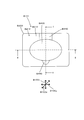
- FIG. 2 is a plan view of the lid body B101 according to the first embodiment.
- the lid B101 includes a base B200, a base opening B300 formed in the base B200, and a covering portion C400 that can cover the base opening B300.
- FIG. 2 shows a state in which the base opening B300 is covered with the covering portion C400.
- the configuration of the base opening B300 will be described later.
- the base B200 is an example of the “base” according to the present invention
- the base opening B300 is an example of the “base opening” according to the present invention
- the covering part B400 is an example of the “covering part” according to the present invention.
- the base B200 has a base first surface B210 and a base second surface B220 which is a surface opposite to the base first surface B210.
- the base first surface B210 is an example of the “base first surface” according to the present invention
- the base second surface B220 is an example of the “base second surface” according to the present invention.
- the covering portion B400 is configured to be able to cover the base opening B300 from the base first surface B210.
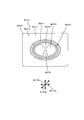
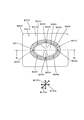
- FIG. 3 is an explanatory diagram in which the covering portion C400 shown in FIG. 2 is omitted.
- the base opening B300 is formed in the central region of the base B200, and is configured such that the sheet D100 taken out from the container opening C300 is inserted.
- a claw B310 is formed from the peripheral region of the base opening B300 toward the inside of the base opening B300.
- the claw portion B310 is configured to apply a predetermined friction force to the sheet body D100 when the sheet body D100 passes through the base opening B300.
- the base B200 includes a first region B211 that is a region including the base opening B300 and a second region B212 that is a region not including the first region B211.
- a second adhesion region B600 that bonds the first region B211 and the covering portion B400 is formed.
- This 2nd adhesion field B600 is an example of the "2nd adhesion field" concerning the present invention. The detailed structure of the second adhesion region B600 will be described later.
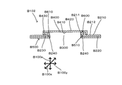
- FIG. 4 is a cross-sectional view taken along the line II shown in FIG.
- a first locking portion B230 is formed on the base B200.
- locking part B230 is formed in the area
- coated part B400 are comprised so that a latching is possible. That is, the state where the first locking portion B230 and the second locking portion B430 are locked is the state where the covering portion B400 covers the base opening B300. This state is referred to as a “closed” state of the lid B101.
- the state where the first locking portion B230 and the second locking portion B430 are unlocked is a state where the covering portion B400 does not cover the base opening B300.
- This state is referred to as “open” state of the lid B101.
- 4 shows a state in which the lid B101 is “closed”
- FIG. 5 shows a state in which the lid B101 is “open”.
- the user prevents the sheet D100 from drying by setting the lid B101 to the “closed” state. And the user can take out the sheet
- a surface of the covering portion B400 facing the base opening B300 is referred to as a covering first surface B410.
- a surface opposite to the coating first surface B410 in the coating part B400 is referred to as a coating second surface B420.
- a second adhesion region B600 that bonds the base B200 and the covering part B400 is formed.
- the second adhesive portion B600 is formed in predetermined regions of the first region B211 and the covered first surface B410.
- the second adhesive region B600 is formed by the second adhesive portion B610 provided in the first region B211.
- This 2nd adhesion part B610 is an example of the "2nd adhesion part" concerning the present invention.
- the second adhesive portion B610 has re-tackiness and can mainly use an elastomer such as urethane, styrene, or acrylic. Further, the second adhesive portion B610 has a predetermined elasticity and is formed so as to protrude on the first region B211.
- the second adhesive portion B610 is fixed to the first region B211.
- the second bonding portion B610 is detachably bonded to the covering first surface B410.
- Such a configuration is achieved by providing an annular groove continuous with the first region B211 and forming the second adhesive B610 in the groove when providing the second adhesive B610.
- a convex part can be provided in the area
- Such a configuration of the second adhesive portion B610 can also be realized by a configuration in which irregularities are formed in a region in contact with the coated first surface B410 in the second adhesive portion B610 or a configuration in which foreign matter is attached. In such a case, the contact area between the second adhesive part B610 and the covering first surface B410 is made smaller than the contact area between the second adhesive part B610 and the first region B211.
- the second bonding portion B610 is detachably bonded to the covering first surface B410.
- a peel strength of 50 g / cm or more is desirable.
- this “desirable peel strength” can be appropriately changed depending on the specific configuration of the locking structure formed by the first locking portion B230 and the second locking portion 430.
- the second adhesive portion B610 has elasticity. As will be described later, the second adhesive portion B610 can ensure the adhesion between the first region B211 and the covering first surface B410 by the elasticity. It is desirable that the elasticity of the second adhesive portion B610 has a size for absorbing the bending of the base portion B200 and the covering portion B400. In normal molding, the base B200 and the cover B400 often have a strain of about 0.2 mm. Therefore, in the case of such molding, it is desirable that the second adhesive portion B610 has an elastic repulsion force of 0.2 mm or more.
- a knob portion B450 that is gripped by the user is formed on one side of the second locking portion B430. Further, on the opposite side of the knob portion B450 of the second locking portion B430, a hinge portion B440 that continues the second locking portion B430 and the base portion B200 is formed.
- the base second surface B220 is formed with a first bonding region B500 that is detachably bonded to the surface portion C210 of the storage container C100. Accordingly, the lid B101 can be attached to and detached from the storage container 500C100.
- This 1st adhesion field B500 is an example of the "1st adhesion field" concerning the present invention.
- the first adhesive region B500 is formed by arranging the first adhesive portion B510 in a predetermined region of the base second surface B220.
- This 1st adhesion part B510 is an example of the "1st adhesion part" concerning the present invention.
- the first adhesive portion B510 is formed of an elastomer such as urethane, styrene, or acrylic.
- the first adhesion region B500 is sufficient if the base second surface B220 and the surface portion C210 of the storage container C100 are configured to be detachable. That is, it is possible to dispose the first adhesive portion B510 in the peripheral region of the container opening C300 without disposing the first adhesive portion B510 on the base second surface B220.
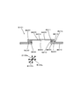
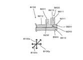
- FIG. 6 is a cross-sectional view taken along the line II-II in FIG. 2, and FIG. 7 is an explanatory diagram showing the configuration of the second adhesive region B600.
- the second adhesive region B600 is formed by disposing the second adhesive portion B610 in the first region B211 of the base B200.
- the second adhesive portion B610 is continuously formed around the base opening B300.
- the second adhesive portion B610 has a surface portion B611.
- the surface portion B611 is formed in the most protruding portion when viewed from the base first surface B210 in the thickness direction B100z.
- the first locking portion B230 of the base portion 200 has a surface portion B231.
- the surface portion B231 is formed at a portion that protrudes most from the base first surface B210 in the thickness direction B100z.
- the surface portion B611 of the second adhesive portion B610 protrudes from the surface portion B231 of the first locking portion B230 when viewed from the base first surface B210 in the thickness direction B100z.
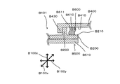
- the user attaches the lid B101 to the new container main body C100. Specifically, the user aligns the container opening C300 and the base opening B300 and attaches the first adhesive part B510 to the surface part C210. In this state, the user opens the lid B201 and takes out the sheet body D100 from the container main body C100 through the base opening B300. And after taking out sheet body D100, lid B201 is closed. In the state where the lid B201 is closed, the covering portion B400 covers the base opening B300 as shown in FIG. At this time, the first locking portion B230 of the base B200 and the second locking portion B430 of the covering portion B400 are locked, so that the covering portion B400 is fixed to the base B200.
- the second bonding portion B610 is compressed between the base first surface B210 and the covering first surface B410. Since the second adhesive portion B610 has elasticity, it is deformed and exhibits a repulsive force. As a result, the surface portion B611 of the second adhesive portion B610 is pressed against the covering first surface B410. As a result, the second bonding portion B610 is bonded to the covering first surface B410. That is, the base B200 and the cover B600 are bonded by the second bonding region B600. As a result, the container body C100 and the lid body B101 form a sealed structure. Therefore, it is possible to prevent the moisture of the sheet body D100 from evaporating.
- the first locking portion B230 and the second locking portion B430 are locked. Therefore, the evaporation of moisture in the sheet body D100 is caused by both the adhesion structure formed by the second bonding portion B610 and the covering first surface B410 and the locking structure formed by the first locking portion B230 and the second locking portion 430. It is prevented.
- the covering part B400 is removed from the base part B200. That is, the engagement state of the first locking portion B230 and the second locking portion B430 is released. In this case, the second adhesive portion B610 and the covering first surface B410 are peeled off.
- the lid body B101 and the sheet body accommodation package A100 according to the first embodiment can prevent the sheet body D100 from being dried by the configuration described above.
- FIG. 9 shows the configuration of the lid B102 according to the second embodiment, and is a view corresponding to FIG. 3 according to the first embodiment.
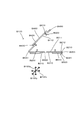
- FIG. 10 is a cross-sectional view taken along line III-III according to FIG. 9, and
- FIG. 11 is an explanatory view of a second adhesion region B600 according to the second embodiment.
- the lid body B102 according to the second embodiment differs from the lid body B101 according to the second embodiment in the configuration of the base 200, the first adhesive region B500, and the second adhesive region B600. That is, as shown in FIG.
- the base B200 according to the second embodiment has a passage part B240 that passes through the base first surface B210 and the base second surface B220.
- This passage portion B240 is an example of the “passage portion” according to the present invention.
- a predetermined number of passage portions B240 are formed in the first region B211 of the base portion B200.
- the first adhesive part B510 and the second adhesive part B610 can be formed simultaneously.
- an adhesive is introduced from the region of the frame where the first adhesive portion B510 is to be formed.
- the adhesive moves to the base first surface B210 through the passage part B240.
- the said adhesive agent is solidified within a predetermined frame in base 1st surface B210, and forms 2nd adhesion part B610.
- the adhesive forms the first adhesive portion B510 on the base second surface B220.
- the adhesive passes from the base first surface B210 to the base second surface through the passage portion B240.
- the first adhesive portion B510 and the second adhesive portion B610 can be easily formed.
- sheet body accommodation package A100 and lid B102 concerning a 2nd embodiment can control drying of sheet body D100 like a 1st embodiment.
- FIG. 12 is an explanatory diagram of the third embodiment, and shows a state corresponding to FIG. 5 according to the first embodiment.
- the sheet body accommodation package A100 and the lid body B103 according to the third embodiment are different in the configuration of the second adhesive region B600 as compared to the first embodiment. That is, in the third embodiment, the second adhesive portion B610 is formed on the covering first surface B410 of the covering portion B400. Also in the lid B103 of the third embodiment, when the base B200 and the covering part B400 are locked, the base B200 and the covering part B400 are bonded by the second bonding region B600. Therefore, the sheet body accommodation package A100 and the lid body B103 according to the third embodiment can suppress the drying of the sheet body D100 as in the first embodiment.
- cover body and sheet body accommodation package which concern on this invention, it is not limited only to the structure described in embodiment mentioned above. That is, a modified example of another configuration can be provided. Moreover, it is also possible to make it the structure which combined each embodiment.
- the sheet body accommodation package A100 is an example of the “sheet body accommodation package” according to the present invention.
- the lid bodies B100, B101, B102, and B103 are examples of the “lid body” according to the present invention.
- the container C100 is an example of the “container body” according to the present invention.
- the sheet body D100 is an example of the “sheet body” according to the present invention.
- the accommodating portion C400 is an example of the “accommodating portion” according to the present invention.
- the container opening C300 is an example of the “container opening” according to the present invention.
- the base B200 is an example of the “base” according to the present invention.
- the base opening B300 is an example embodiment that corresponds to the “base opening” according to the present invention.
- the covering portion B400 is an example of the “covering portion” according to the present invention.
- the base first surface B210 is an example embodiment that corresponds to the “base first surface” according to the present invention.
- the base second surface B220 is an example embodiment that corresponds to the “base second surface” according to the present invention.
- the second adhesion region B600 is an example of the “second adhesion region” according to the present invention.
- 2nd adhesion part B610 is an example of the "2nd adhesion part” concerning the present invention.
- the first adhesion region B500 is an example of the “first adhesion region” according to the present invention.
- the first adhesive portion B510 is an example of the “first adhesive portion” according to the present invention.
- the passage portion B240 is an example of the “passage portion” according to the present invention.
Landscapes
- Engineering & Computer Science (AREA)
- Mechanical Engineering (AREA)
- Health & Medical Sciences (AREA)
- Public Health (AREA)
- Epidemiology (AREA)
- General Health & Medical Sciences (AREA)
- Packages (AREA)
- Containers And Packaging Bodies Having A Special Means To Remove Contents (AREA)
- Closures For Containers (AREA)
- Piezo-Electric Or Mechanical Vibrators, Or Delay Or Filter Circuits (AREA)
Abstract
本発明は、蓋体B100を有するシート体収容パッケージに関し、蓋体B100は、基部開口B300を有する基部B200と、被覆部B400とを有し、被覆部B400が基部開口B200を被覆した状態において、基部B200と被覆部B400とを接着する第2接着領域B600が形成されるものであり、蓋体およびシート体収容部パッケージに関する一層合理的な構築技術を提供する。
Description
本発明は、シート体の収容容器に取り付けるための蓋体に関し、さらに、蓋体とシート体の収容容器とを有するシート体収容パッケージに関する。
湿潤されたシート体を収容するための可撓性の収容容器に使用する蓋体が、特開平11-70056号に開示されている。当該特許文献の蓋体は、シート体を取出す開口と、当該開口を被覆する被覆部を有しており、シート体の収容容器に取付けることにより使用される。
一方、当該特許文献の蓋体は、被覆部と蓋体の本体とを嵌合して係止する構造であったため密閉性が十分ではなく、シート体の乾燥を招きやすいと言う問題点があった。
一方、当該特許文献の蓋体は、被覆部と蓋体の本体とを嵌合して係止する構造であったため密閉性が十分ではなく、シート体の乾燥を招きやすいと言う問題点があった。
本発明は、このような点に鑑みて創案されたものであり、シート体の収容容器に使用する蓋体、および蓋体とシート体の収容容器を有するシート体収容パッケージに関する一層合理的な構築技術を提供することを目的とする。
上記課題を解決するため、本発明に係る蓋体は、湿潤されたシート体を収容する収容部と、収容部に収容されたシート体を取り出すための容器開口とを有する容器本体に接着され、基部と、被覆部とを有する。
基部は、一方側の面である基部第1面と、基部第1面とは反対側の面である基部第2面と、基部開口と、基部第2面に形成された第1接着領域とを有する。被覆部は、基部第1面から基部開口を被覆可能に形成されるとともに、被覆部が基部開口を被覆した状態において基部第1面と向かい合う面である被覆第1面と、被覆第1面とは反対側の面である被覆第2面とを有する。そして、被覆部が基部開口を被覆した状態における基部第1面と被覆第1面との間に、基部第1面と被覆第1面とを接着する第2接着領域が形成される。
基部は、一方側の面である基部第1面と、基部第1面とは反対側の面である基部第2面と、基部開口と、基部第2面に形成された第1接着領域とを有する。被覆部は、基部第1面から基部開口を被覆可能に形成されるとともに、被覆部が基部開口を被覆した状態において基部第1面と向かい合う面である被覆第1面と、被覆第1面とは反対側の面である被覆第2面とを有する。そして、被覆部が基部開口を被覆した状態における基部第1面と被覆第1面との間に、基部第1面と被覆第1面とを接着する第2接着領域が形成される。
本発明に係る蓋体によれば、被覆部が基部開口を被覆した状態において、被覆部と基部とが第2接着領域によって接着される。よって、蓋体の密閉性を向上させることが可能となるため、シート体の乾燥を抑制することができる。
また本発明に係る蓋体における解決手段の一態様として、第1接着領域は、接着剤により形成される第1接着部を有し、第2接着領域は、接着剤により形成される第2接着部を有する。
また本発明に係る蓋体における解決手段の一態様として、第2接着部は、弾性を有する。
本態様に係る蓋体によれば、被覆部が基部開口を被覆した場合に、第2接着部が圧縮される。第2接着部は弾性を有しているため、基部第1面と被覆第1面との間で反発力を発現し、基部第1面と被覆第1面とに押し付けられる。すなわち、本態様に係る蓋体によれば、第2接着領域における基部第1面と被覆第1面との接着状態を確実なものとすることができる。
本態様に係る蓋体によれば、被覆部が基部開口を被覆した場合に、第2接着部が圧縮される。第2接着部は弾性を有しているため、基部第1面と被覆第1面との間で反発力を発現し、基部第1面と被覆第1面とに押し付けられる。すなわち、本態様に係る蓋体によれば、第2接着領域における基部第1面と被覆第1面との接着状態を確実なものとすることができる。
また本発明に係る蓋体における解決手段の一態様として、第2接着部を、基部第1面に形成することができる。
また本発明に係る蓋体における解決手段の一態様として、基部は、基部第1面と基部第2面とを挿通する通路部を有することができる。さらに、第1接着部と第2接着部とを、通路部を介して連続することができる。
本態様に係る蓋体によれば、蓋体の製造において、第1接着部を形成するために基部第1面から供給された接着剤を、通路部を介して基部第2面へ導くことが可能となる。すなわち、基部の一方の面から供給した接着剤により、基部の他方の面の接着部を形成することができる。よって、本態様に係る蓋体によれば、製造コストの低減を図ることが可能となる。
また本発明に係る蓋体における解決手段の一態様として、第2接着部を、被覆第1面に形成することができる。
また本発明に係るシート体収容パッケージにおける解決手段の一態様として、湿潤されたシート体を収容する収容部と、収容部に収容されたシート体を取り出すための容器開口とを有する容器本体と、容器本体に接着される蓋体と有することができる。
蓋体は、基部と、被覆部とを有する。基部は、一方側の面である基部第1面と、基部第1面とは反対側の面である基部第2面と、容器開口から取り出されたシート体を挿通する基部開口と、基部第2面に形成された第1接着領域とを有する。被覆部は、基部第1面から基部開口を被覆可能に形成されるとともに、被覆部が基部開口を被覆した状態において基部第1面と向かい合う面である被覆第1面と、被覆第1面とは反対側の面である被覆第2面とを有する。そして、被覆部が基部開口を被覆した状態における基部第1面と被覆第1面との間に、基部第1面と被覆第1面とを接着する第2接着領域が形成される。
蓋体は、基部と、被覆部とを有する。基部は、一方側の面である基部第1面と、基部第1面とは反対側の面である基部第2面と、容器開口から取り出されたシート体を挿通する基部開口と、基部第2面に形成された第1接着領域とを有する。被覆部は、基部第1面から基部開口を被覆可能に形成されるとともに、被覆部が基部開口を被覆した状態において基部第1面と向かい合う面である被覆第1面と、被覆第1面とは反対側の面である被覆第2面とを有する。そして、被覆部が基部開口を被覆した状態における基部第1面と被覆第1面との間に、基部第1面と被覆第1面とを接着する第2接着領域が形成される。
本発明に係るシート体収容パッケージによれば、被覆部が基部開口を被覆した状態において、被覆部と基部とが第2接着領域によって接着される。よって、蓋体の密閉性を向上させることが可能となるため、収容体に収容されているシート体の乾燥を抑制することができる。
本発明によれば、シート体の収容容器に使用する蓋体、および蓋体とシート体の収容容器を有するシート体収容パッケージに関する一層合理的な構築技術を提供することが可能となる。
(シート体収容パッケージの基本構成)
図1に基づき、本発明に係るシート体収容パッケージA100の基本構成を説明する。シート体収容パッケージA100は、収容容器C100と、蓋体B100とにより構成される。蓋体B100は、収容容器C100に剥離可能に接着される。すなわち、例えば収容容器C100に収容されたシート体E100が無くなった場合、蓋体B100を収容容器C100から剥離し、新たな収容容器C100に取り付けることが可能である。
蓋体B100は、第1実施形態として図2~図8に係る蓋体B101が、第2実施形態として図9~図11に係る蓋体B102が、第3実施形態として図12に係る蓋体B103がそれぞれ示される。
このシート体収容パッケージA100が本発明に係る「シート体収容パッケージ」の一例であり、蓋体B100、B101、B102およびB103が本発明に係る「蓋体」の一例であり、収容容器C100が本発明に係る「容器本体」の一例である。
図1に示す通り、収容容器C100は、シート体D100を収容する収容部C400を有する。このシート体D100が本発明に係る「シート体」の一例であり、収容部C400が本発明に係る「収容部」の一例である。さらに、収容体C100の表面部C210には、シート体D100を取出すための容器開口C300が形成される。この容器開口C300が本発明に係る「容器開口」の一例である。
シート体D100は、湿潤されている。具体的には、シート体D100は繊維材料をシート状に形成したティッシュペーパーや不織布等に薬剤、化粧水やアルコール等の液体を含浸させた種々のウェットティッシュにより構成される。便宜上、図1においては省略するが、シート体D100は複数枚が積層される。この際、シート体D100は、隣接するシート体D100の端部が重なるように折り返されており、一枚のシート体D100を収容容器C100から取り出した場合に、次のシート体D100の端部が露出するように構成される。
シート体D100は、湿潤されている。具体的には、シート体D100は繊維材料をシート状に形成したティッシュペーパーや不織布等に薬剤、化粧水やアルコール等の液体を含浸させた種々のウェットティッシュにより構成される。便宜上、図1においては省略するが、シート体D100は複数枚が積層される。この際、シート体D100は、隣接するシート体D100の端部が重なるように折り返されており、一枚のシート体D100を収容容器C100から取り出した場合に、次のシート体D100の端部が露出するように構成される。
図1に示す通り、収容容器C100の外郭部C200はフィルムにより構成されており、可撓性を有する。フィルムは、加熱することによって融着可能なフィルム(「熱融着フィルム」という)によって形成される。熱融着フィルムとしては、例えば、ポリエチレンテレフタレート(PET)樹脂により形成された保護層、アルミニウムにより形成された湿潤保持層(乾燥防止層)、二軸延伸ポリプロピレン樹脂により形成された熱融着層(ヒートシール層)が積層された積層フィルム(ラミネートフィルム)等が用いられる。このフィルムは防湿性を備えているため、シート体D100に含浸された液体が、外郭部C200を通して蒸発しにくい構成とされている。
収容容器C100は、長手方向C100yと、当該長手方向C100yと交差する方向である長手交差方向C100xと、長手方向C100yと長手交差方向C100xの双方に交差する方向である厚さ方向C100zとを規定する。
蓋体は、長手方向B100yと、当該長手方向B100yと交差する方向である長手交差方向B100xと、長手方向B100yと長手交差方向B100xの双方に交差する方向である厚さ方向B100zとを規定する。
なお、収容容器C100もしくは蓋体B100が正方形や円形であった場合には、それぞれの長手方向(C100y、B100y)は、任意の方向とされる。
蓋体は、長手方向B100yと、当該長手方向B100yと交差する方向である長手交差方向B100xと、長手方向B100yと長手交差方向B100xの双方に交差する方向である厚さ方向B100zとを規定する。
なお、収容容器C100もしくは蓋体B100が正方形や円形であった場合には、それぞれの長手方向(C100y、B100y)は、任意の方向とされる。
蓋体B100は、気密性の確保という意味において、インジェクション成型やバキューム成型により形成することが好ましい。インジェクション成型の場合は、ポリエチレンやポリプロピレンなどが好適に使用される。バキューム成型の場合は、ポリエチレン、ポリプロピレン、非晶性ポリエチレンテレフタレート(A-PET)などが好適に使用される。
蓋体B100には、蓋体B100と収容容器C100とを接着する第1接着領域B500と、蓋体B100における基部B200と被覆部B400とを接着する第2接着領域B600とが形成される。蓋体B100の詳細な構造にあっては、図2~図12に示す第1実施形態~第4実施形態に基づき後述する。この際、蓋体B100、収容容器C100およびシート体D100の構成にあっては、各実施形態に共通のためその説明を省略する。
蓋体B100には、蓋体B100と収容容器C100とを接着する第1接着領域B500と、蓋体B100における基部B200と被覆部B400とを接着する第2接着領域B600とが形成される。蓋体B100の詳細な構造にあっては、図2~図12に示す第1実施形態~第4実施形態に基づき後述する。この際、蓋体B100、収容容器C100およびシート体D100の構成にあっては、各実施形態に共通のためその説明を省略する。
(第1実施形態)
図2~図8に基づき、第1実施形態に係る蓋体B101およびシート体収容パッケージA100の構成を説明する。図2は、第1実施形態に係る蓋体B101の平面図である。蓋体B101は、基部B200と、当該基部B200に形成される基部開口B300と、当該基部開口B300を被覆可能な被覆部C400を有する。なお、図2は、基部開口B300を被覆部C400が被覆した状態を示す。基部開口B300の構成は後述する。
この基部B200が本発明に係る「基部」の一例であり、基部開口B300が本発明に係る「基部開口」の一例であり、被覆部B400が本発明に係る「被覆部」の一例である。
図2~図8に基づき、第1実施形態に係る蓋体B101およびシート体収容パッケージA100の構成を説明する。図2は、第1実施形態に係る蓋体B101の平面図である。蓋体B101は、基部B200と、当該基部B200に形成される基部開口B300と、当該基部開口B300を被覆可能な被覆部C400を有する。なお、図2は、基部開口B300を被覆部C400が被覆した状態を示す。基部開口B300の構成は後述する。
この基部B200が本発明に係る「基部」の一例であり、基部開口B300が本発明に係る「基部開口」の一例であり、被覆部B400が本発明に係る「被覆部」の一例である。
図2および図4に示す通り、基部B200は、基部第1面B210と、当該基部第1面B210とは反対側の面である基部第2面B220とを有する。この基部第1面B210が本発明に係る「基部第1面」の一例であり、この基部第2面B220が本発明に係る「基部第2面」の一例である。被覆部B400は、基部第1面B210から基部開口B300を被覆可能に構成されている。
図3は、図2に示す被覆部C400を省略した説明図である。基部開口B300は、基部B200の中央領域に形成されており、容器開口C300から取り出されたシートD100が挿通されるように構成される。基部開口B300の周辺領域から基部開口B300の内側方向へ向かい、爪部B310が形成されている。爪部B310は、シート体D100が基部開口B300を通過する際に、シート体D100に対して所定の摩擦力を加えるように構成される。
基部B200は、基部開口B300を含む領域である第1領域B211と、第1領域B211を含まない領域である第2領域B212とを有する。第1領域B211には、当該第1領域B211と、被覆部B400とを接着する第2接着領域B600が形成される。この第2接着領域B600が、本発明に係る「第2接着領域」の一例である。第2接着領域B600の詳細な構造については、後述する。
基部B200は、基部開口B300を含む領域である第1領域B211と、第1領域B211を含まない領域である第2領域B212とを有する。第1領域B211には、当該第1領域B211と、被覆部B400とを接着する第2接着領域B600が形成される。この第2接着領域B600が、本発明に係る「第2接着領域」の一例である。第2接着領域B600の詳細な構造については、後述する。
図4は、図2に示すI-I線断面図である。基部B200には、第1係止部B230が形成される。本実施形態においては、第1係止部B230は、第1領域B211および第2領域B212に対し突出する領域にて形成される。第1係止部B230と、被覆部B400の周縁領域に形成された第2係止部B430とは係止可能に構成される。すなわち、第1係止部B230と第2係止部B430が係止している状態は、被覆部B400が基部開口B300を被覆している状態となる。この状態を、蓋体B101が「閉じた」状態と称する。一方、第1係止部B230と第2係止部B430とが係止を解除している状態は、被覆部B400が基部開口B300を被覆していない状態となる。この状態を、蓋体B101が「開いた」状態と称する。図4は、蓋体B101が「閉じた」状態を示し、図5は、蓋体B101が「開いた」状態を示す。
使用者は、蓋体B101を「閉じた」状態とすることで、シート体D100の乾燥を防止する。そして、使用者は、蓋体B101を「開いた」状態とすることで、図1に示される収容部C400のシート体D100を、容器開口C300および基部開口B300を通じて取り出すことができる。
蓋体B101が「閉じた」状態において、被覆部B400における基部開口B300と向かい合う面を被覆第1面B410と称する。被覆部B400における被覆第1面B410とは反対側の面を、被覆第2面B420とする。
使用者は、蓋体B101を「閉じた」状態とすることで、シート体D100の乾燥を防止する。そして、使用者は、蓋体B101を「開いた」状態とすることで、図1に示される収容部C400のシート体D100を、容器開口C300および基部開口B300を通じて取り出すことができる。
蓋体B101が「閉じた」状態において、被覆部B400における基部開口B300と向かい合う面を被覆第1面B410と称する。被覆部B400における被覆第1面B410とは反対側の面を、被覆第2面B420とする。
蓋体B101を閉じた状態において、基部B200と被覆部B400とを接着する第2接着領域B600が形成される。具体的には、第2接着部B600は、第1領域B211と被覆第1面B410の所定領域に形成される。第1実施形態において、第2接着領域B600は、第1領域B211に設けられた第2接着部B610により形成される。この第2接着部B610が、本発明に係る「第2接着部」の一例である。
第2接着部B610は、再粘着性を有しており、ウレタン系、スチレン系、アクリル系等のエラストマーを主に使用することができる。また、第2接着部B610は所定の弾性を有し、第1領域B211上に突出して形成される。
第2接着部B610は、再粘着性を有しており、ウレタン系、スチレン系、アクリル系等のエラストマーを主に使用することができる。また、第2接着部B610は所定の弾性を有し、第1領域B211上に突出して形成される。
第2接着部B610は、第1領域B211に対しては固定されている。一方、第2接着部B610は、被覆第1面B410に対しては、剥離可能に接着される。このような構成は、第2接着部B610を設けるにあたり、第1領域B211に連続した環状の溝部を設け、当該溝部に第2接着部B610を形成することにより達成される。
また、被覆第1面B410における第2接着部B610と当接する領域に凸部を設けることができる。この際、第2接着部B610が第1領域B211に接触する面積の方が、被覆第1面B410の凸部に接触する面積よりも大きくなるように、凸部を形成する。このような構成とすることで、第1領域B211に固定されるともに被覆第1面B410に対して剥離可能な第2接着部B610を形成することができる。
また、このような第2接着部B610の構成は、第2接着部B610における被覆第1面B410に接触する領域に凹凸を形成する構成や、異物を付着する構成によっても実現することができる。このような場合は、第2接着部B610と被覆第1面B410との接触面積が、第2接着部B610と第1領域B211との接触面積よりも少なくされる。
第2接着部B610は、被覆第1面B410に対し剥離可能に接着される。第2接着部B610が被覆第1面B410に対し接着された状態にあっては、例えば、使用者がシート体収容パッケージA100を持ち歩いた際に、容易に剥離しない程度であることが望ましい。具体的には、50g/cm以上の剥離強度であることが望ましい。一方、この「望ましい剥離強度」については、第1係止部B230と第2係止部430とによる係止構造の具体的な構成により、適宜変更することが可能である。
第2接着部B610は、弾性を有する。後述の通り、第2接着部B610は当該弾性により、第1領域B211と被覆第1面B410との接着を確実なものとすることができる。第2接着部B610の弾性は、基部B200や被覆部B400の撓みを吸収するための大きさを有することが望ましい。通常の成型にあっては、基部B200や被覆部B400は0.2mm程度の歪みが発生することが多い。よって、このような成型の場合には、第2接着部B610は、0.2mm以上の弾性反発力を有することが望ましい。
図4および図5に示す通り、第2係止部B430の一方側には、使用者に把持される摘み部B450が形成される。また、第2係止部B430の摘み部B450とは反対側には、第2係止部B430と基部B200とを連続するヒンジ部B440が形成される。
また、基部第2面B220は、収容容器C100の表面部C210に対し剥離可能に接着される第1接着領域B500が形成される。これにより蓋体B101は収容容器500C100に対して着脱可能とされる。この第1接着領域B500が、本発明に係る「第1接着領域」の一例である。
第1接着領域B500は、第1接着部B510が基部第2面B220の所定領域に配置されることにより形成される。この第1接着部B510が、本発明に係る「第1接着部」の一例である。第1接着部B510は、ウレタン系、スチレン系、アクリル系等のエラストマーにより形成される。第1接着領域B500は、基部第2面B220と収容容器C100の表面部C210とを着脱自在に構成すれば足りるものである。すなわち、基部第2面B220に第1接着部B510を配置せずに、容器開口C300の周辺領域に第1接着部B510を配置することも可能である。
(第2粘着領域の構成)
次に、図6~図8に基づき、第2粘着領域B600の構成につき説明する。図6は、図2におけるII-II線の断面図、図7は第2粘着領域B600の構成を示す説明図である。
第2粘着領域B600は、基部B200の第1領域B211に第2粘着部B610を配置することにより形成される。第2粘着部B610は、基部開口B300の周囲に連続して形成される。
図7に示す通り、第2粘着部B610は表面部B611を有する。表面部B611は、厚み方向B100zにおいて、基部第1面B210からみて最も突出した部分に形成される。基部200の第1係止部B230は表面部B231を有する。表面部B231は、厚み方向B100zにおいて、基部第1面B210からみて最も突出した部分に形成される。第2粘着部B610の表面部B611は、厚み方向B100zにおいて、基部第1面B210からみて第1係止部B230の表面部B231よりも突出している。
(第2接着領域の動作)
次に、図8に基づき第2接着領域B600の動作につき説明を行う。使用者は、まず、新品の容器本体C100に対し、蓋体B101を取り付ける。具体的には、使用者は、容器開口C300と基部開口B300との位置合わせを行うとともに、第1接着部B510を表面部C210に貼り付ける。
この状態において、使用者は、蓋体B201を開いた状態とし、シート体D100を容器本体C100から、基部開口B300を通じて取り出す。そして、シート体D100を取出した後、蓋体B201を閉じる。蓋体B201を閉じた状態においては、図8に示す通り、被覆部B400が基部開口B300を被覆する。この際、基部B200の第1係止部B230と、被覆部B400の第2係止部B430とが係止することによって、被覆部B400は、基部B200に対し固定される。
この状態において、第2接着部B610は、基部第1面B210と被覆第1面B410との間で圧縮される。第2接着部B610は、弾性を有するため変形し反発力を発現する。この結果、第2接着部B610の表面部B611は、被覆第1面B410に押し当てられる。これによって、第2接着部B610は、被覆第1面B410に対し接着される。すなわち、第2接着領域B600によって、基部B200と被覆部B600とが接着される。この結果、容器本体C100と蓋体B101とは、密封した構造を形成する。よって、シート体D100の水分の蒸発を防ぐことが可能となる。なお、この場合、第1係止部B230と第2係止部B430とが係止している。よって、シート体D100の水分の蒸発は、第2接着部B610と被覆第1面B410とによる接着構造と、第1係止部B230と第2係止部430とによる係止構造との双方により防がれる。
使用者が、シート体D100をシート体収容パッケージA100から取り出す場合には、被覆部B400を基部B200から取り外す。すなわち、第1係止部B230と第2係止部B430の係合状態を解除する。この場合、第2接着部B610と被覆第1面B410とは剥離される。
第1実施形態に係る蓋体B101およびシート体収容パッケージA100は、上述した構成により、シート体D100の乾燥を防止することが可能となる。
使用者が、シート体D100をシート体収容パッケージA100から取り出す場合には、被覆部B400を基部B200から取り外す。すなわち、第1係止部B230と第2係止部B430の係合状態を解除する。この場合、第2接着部B610と被覆第1面B410とは剥離される。
第1実施形態に係る蓋体B101およびシート体収容パッケージA100は、上述した構成により、シート体D100の乾燥を防止することが可能となる。
(第2実施形態)
次に、本発明に係る第2実施形態を、図9~図11に基づき説明する。図9は、第2実施形態に係る蓋体B102の構成を示すものであり、第1実施形態に係る図3に相当する図である。図10は、図9に係るIII-III線断面図であり、図11は、第2実施例に係る第2接着領域B600の説明図である。
第2実施形態に係る蓋体B102は、第2実施形態に係る蓋体B101と比して、基部200、第1接着領域B500および第2接着領域B600の構成が異なる。すなわち、図10に示す通り、第2実施形態に係る基部B200は、基部第1面B210と基部第2面B220とを挿通する通路部B240を有する。この通路部B240が、本発明に係る「通路部」の一例である。図9に示す通り、通路部B240は、基部B200の第1領域B211において、所定の数にて形成される。
通路部B240を設けることで、第1接着部B510と第2接着部B610とを同時に形成することができる。例えば、基部B200を所定の枠体に配置した後、第1接着部B510が形成されるべき枠体の領域から接着剤を流入する。すると、当該接着剤は、通路部B240を通じて基部第1面B210に移動する。そして、当該接着剤は、基部第1面B210において、所定の枠体内にて固化して第2接着部B610を形成する。また、当該接着剤は、基部第2面B220にて第1接着部B510を形成する。
なお、第2接着部B610が形成されるべき枠体の領域から接着剤を流入することも可能であり、この場合は、接着剤が通路部B240を通じて、基部第1面B210から基部第2面へ移動し、第1接着部B510および第2接着部B610を形成する。
すなわち、第2実施形態によれば、基部B200に通路部B240を形成することにより、第1接着部B510と第2接着部B610とを容易に形成することが可能となる。
なお、第2接着部B610が形成されるべき枠体の領域から接着剤を流入することも可能であり、この場合は、接着剤が通路部B240を通じて、基部第1面B210から基部第2面へ移動し、第1接着部B510および第2接着部B610を形成する。
すなわち、第2実施形態によれば、基部B200に通路部B240を形成することにより、第1接着部B510と第2接着部B610とを容易に形成することが可能となる。
なお、図11に示す通り、第2接着部B610の表面部B611と、第1係止部B230の表面部B231との厚さ方向B100zにおける位置関係は、第1実施形態と同様である。
よって、第2実施形態に係るシート体収容パッケージA100および蓋体B102は、第1実施形態と同様にシート体D100の乾燥を抑制することが可能となる。
よって、第2実施形態に係るシート体収容パッケージA100および蓋体B102は、第1実施形態と同様にシート体D100の乾燥を抑制することが可能となる。
(第3実施形態)
次に、本発明に係る第3実施形態を、図12に基づき説明する。図12は、第3実施形態の説明図であり、第1実施形態に係る図5に相当する状態を示す。
第3実施形態に係るシート体収容パッケージA100および蓋体B103は、第1実施形態と比して第2接着領域B600の構成が異なる。すなわち、第3実施形態においては、第2接着部B610が、被覆部B400の被覆第1面B410に形成される。
第3実施形態の蓋体B103においても、基部B200と被覆部B400を係止した場合には、第2接着領域B600によって、基部B200と被覆部B400とが接着される。
よって、第3実施形態に係るシート体収容パッケージA100および蓋体B103は、第1実施形態と同様にシート体D100の乾燥を抑制することが可能となる。
なお、本発明に係る蓋体およびシート体収容パッケージにあっては、上述した実施形態に記載した構成にのみ限定されるものではない。すなわち、さらに他の構成の変形例とすることが可能である。また、それぞれの実施形態を組み合わせた構成とすることも可能である。
(実施の形態ないし実施例本発明の各構成要素の対応について)
シート体収容パッケージA100は、本発明に係る「シート体収容パッケージ」の一例である。蓋体B100、B101、B102およびB103は、本発明に係る「蓋体」の一例である。収容容器C100は、本発明に係る「容器本体」の一例である。シート体D100は、本発明に係る「シート体」の一例である。収容部C400は、本発明に係る「収容部」の一例である。容器開口C300は、本発明に係る「容器開口」の一例である。基部B200は、本発明に係る「基部」の一例である。基部開口B300は、本発明に係る「基部開口」の一例である。被覆部B400は、本発明に係る「被覆部」の一例である。基部第1面B210は、本発明に係る「基部第1面」の一例である。基部第2面B220は、本発明に係る「基部第2面」の一例である。第2接着領域B600は、本発明に係る「第2接着領域」の一例である。第2接着部B610は、本発明に係る「第2接着部」の一例である。第1接着領域B500は、本発明に係る「第1接着領域」の一例である。第1接着部B510は、本発明に係る「第1接着部」の一例である。通路部B240は、本発明に係る「通路部」の一例である。
シート体収容パッケージA100は、本発明に係る「シート体収容パッケージ」の一例である。蓋体B100、B101、B102およびB103は、本発明に係る「蓋体」の一例である。収容容器C100は、本発明に係る「容器本体」の一例である。シート体D100は、本発明に係る「シート体」の一例である。収容部C400は、本発明に係る「収容部」の一例である。容器開口C300は、本発明に係る「容器開口」の一例である。基部B200は、本発明に係る「基部」の一例である。基部開口B300は、本発明に係る「基部開口」の一例である。被覆部B400は、本発明に係る「被覆部」の一例である。基部第1面B210は、本発明に係る「基部第1面」の一例である。基部第2面B220は、本発明に係る「基部第2面」の一例である。第2接着領域B600は、本発明に係る「第2接着領域」の一例である。第2接着部B610は、本発明に係る「第2接着部」の一例である。第1接着領域B500は、本発明に係る「第1接着領域」の一例である。第1接着部B510は、本発明に係る「第1接着部」の一例である。通路部B240は、本発明に係る「通路部」の一例である。
A100 シート体収容パッケージ
B100、B101、B102、B103 蓋体
B100x 長手交差方向
B100y 長手方向
B100z 厚さ方向
B200 基部
B210 基部第1面
B211 第1領域
B212 第2領域
B220 基部第2面
B230 第1係止部
B231 表面部
B240 通路部
B300 基部開口
B310 爪部
B400 被覆部
B410 被覆第1面
B420 被覆第2面
B430 第2係止部
B440 ヒンジ部
B450 摘み部
B500 第1接着領域
B510 第1接着部
B600 第2接着領域
B610 第2接着部
B611 表面部
C100 収容容器(容器本体)
C100x 長手交差方向
C100y 長手方向
C100z 厚さ方向
C200 外郭部
C210 表面部
C300 容器開口
C400 収容部
D100 シート体
Claims (7)
- 湿潤されたシート体を収容する収容部と、前記収容部に収容された前記シート体を取り出すための容器開口とを有する容器本体に接着される蓋体であって、
基部と、被覆部とを有し、
前記基部は、一方側の面である基部第1面と、前記基部第1面とは反対側の面である基部第2面と、基部開口と、前記基部第2面に形成された第1接着領域とを有し、
前記被覆部は、前記基部第1面から前記基部開口を被覆可能に形成されるとともに、前記被覆部が前記基部開口を被覆した状態において前記基部第1面と向かい合う面である被覆第1面と、前記被覆第1面とは反対側の面である被覆第2面とを有し、
前記被覆部が前記基部開口を被覆した状態における前記基部第1面と前記被覆第1面との間に、前記基部第1面と前記被覆第1面とを接着する第2接着領域が形成されることを特徴とする蓋体。 - 請求項1に記載された蓋体であって、
前記第1接着領域は、接着剤により形成される第1接着部を有し、
前記第2接着領域は、接着剤により形成される第2接着部を有することを特徴とする蓋体。 - 請求項1または2に記載された蓋体であって、
前記第2接着部は、弾性を有することを特徴とする蓋体。 - 請求項1~3のいずれか1項に記載された蓋体であって、
前記第2接着部は、前記基部第1面に形成されることを特徴とする蓋体。 - 請求項4に記載された蓋体であって、
前記基部は、前記基部第1面と前記基部第2面とを挿通する通路部を有し、
前記第1接着部と前記第2接着部は前記通路部を介して連続されていることを特徴とする蓋体。 - 請求項1~3のいずれか1項に記載された蓋体であって、
前記第2接着部は、前記被覆第1面に形成されることを特徴とする蓋体。 - 湿潤されたシート体を収容する収容部と、前記収容部に収容された前記シート体を取り出すための容器開口とを有する容器本体と、前記容器本体に接着される蓋体とを有するシート体収容パッケージであって、
前記蓋体は、基部と、被覆部とを有し、
前記基部は、一方側の面である基部第1面と、前記基部第1面とは反対側の面である基部第2面と、前記容器開口から取り出された前記シート体を挿通する基部開口と、前記基部第2面に形成された第1接着領域とを有し、
前記被覆部は、前記基部第1面から前記基部開口を被覆可能に形成されるとともに、前記被覆部が前記基部開口を被覆した状態において前記基部第1面と向かい合う面である被覆第1面と、前記被覆第1面とは反対側の面である被覆第2面とを有し、
前記被覆部が前記基部開口を被覆した状態における前記基部第1面と前記被覆第1面との間に、前記基部第1面と前記被覆第1面とを接着する第2接着領域が形成されることを特徴とするシート体収容パッケージ。
Priority Applications (2)
| Application Number | Priority Date | Filing Date | Title |
|---|---|---|---|
| CN201580042777.7A CN106660689B (zh) | 2014-06-27 | 2015-06-17 | 盖体以及片体收容包装体 |
| KR1020177002547A KR20170024066A (ko) | 2014-06-27 | 2015-06-17 | 덮개 및 시트체 수용 패키지 |
Applications Claiming Priority (2)
| Application Number | Priority Date | Filing Date | Title |
|---|---|---|---|
| JP2014132942A JP6429365B2 (ja) | 2014-06-27 | 2014-06-27 | 蓋体およびシート体収容パッケージ |
| JP2014-132942 | 2014-06-27 |
Publications (1)
| Publication Number | Publication Date |
|---|---|
| WO2015198952A1 true WO2015198952A1 (ja) | 2015-12-30 |
Family
ID=54938038
Family Applications (1)
| Application Number | Title | Priority Date | Filing Date |
|---|---|---|---|
| PCT/JP2015/067528 Ceased WO2015198952A1 (ja) | 2014-06-27 | 2015-06-17 | 蓋体およびシート体収容パッケージ |
Country Status (5)
| Country | Link |
|---|---|
| JP (1) | JP6429365B2 (ja) |
| KR (1) | KR20170024066A (ja) |
| CN (1) | CN106660689B (ja) |
| MY (1) | MY180609A (ja) |
| WO (1) | WO2015198952A1 (ja) |
Citations (5)
| Publication number | Priority date | Publication date | Assignee | Title |
|---|---|---|---|---|
| JPH09156676A (ja) * | 1995-10-06 | 1997-06-17 | Berusante:Kk | ウエットティッシュ包装体 |
| JPH10179443A (ja) * | 1996-12-27 | 1998-07-07 | Bell Sante:Kk | ウエットティッシュ包装体セット |
| JP2000142842A (ja) * | 1998-10-30 | 2000-05-23 | Pigeon Corp | ウエット材料の収容容器 |
| JP2010115383A (ja) * | 2008-11-14 | 2010-05-27 | Uni Charm Corp | ウェットティッシュ包装体の収納容器 |
| JP2011111195A (ja) * | 2009-11-27 | 2011-06-09 | Eri Shimizu | ウェットティッシュ収納容器の取出口カバー |
Family Cites Families (2)
| Publication number | Priority date | Publication date | Assignee | Title |
|---|---|---|---|---|
| CN201313705Y (zh) * | 2008-12-17 | 2009-09-23 | 蔡世军 | 一种湿巾盒 |
| KR101170056B1 (ko) | 2010-06-03 | 2012-07-31 | 최슬기 | 의료용 영상장비를 이용한 치아 보철기구 제조 방법 |
-
2014
- 2014-06-27 JP JP2014132942A patent/JP6429365B2/ja not_active Expired - Fee Related
-
2015
- 2015-06-17 KR KR1020177002547A patent/KR20170024066A/ko not_active Ceased
- 2015-06-17 CN CN201580042777.7A patent/CN106660689B/zh not_active Expired - Fee Related
- 2015-06-17 MY MYPI2016704749A patent/MY180609A/en unknown
- 2015-06-17 WO PCT/JP2015/067528 patent/WO2015198952A1/ja not_active Ceased
Patent Citations (5)
| Publication number | Priority date | Publication date | Assignee | Title |
|---|---|---|---|---|
| JPH09156676A (ja) * | 1995-10-06 | 1997-06-17 | Berusante:Kk | ウエットティッシュ包装体 |
| JPH10179443A (ja) * | 1996-12-27 | 1998-07-07 | Bell Sante:Kk | ウエットティッシュ包装体セット |
| JP2000142842A (ja) * | 1998-10-30 | 2000-05-23 | Pigeon Corp | ウエット材料の収容容器 |
| JP2010115383A (ja) * | 2008-11-14 | 2010-05-27 | Uni Charm Corp | ウェットティッシュ包装体の収納容器 |
| JP2011111195A (ja) * | 2009-11-27 | 2011-06-09 | Eri Shimizu | ウェットティッシュ収納容器の取出口カバー |
Also Published As
| Publication number | Publication date |
|---|---|
| JP6429365B2 (ja) | 2018-11-28 |
| JP2016010468A (ja) | 2016-01-21 |
| CN106660689B (zh) | 2019-07-05 |
| CN106660689A (zh) | 2017-05-10 |
| KR20170024066A (ko) | 2017-03-06 |
| MY180609A (en) | 2020-12-03 |
Similar Documents
| Publication | Publication Date | Title |
|---|---|---|
| TR201808461T4 (tr) | Islak mendil paket gövdesi için kapak gövdesi ve ıslak mendil paket gövdesi. | |
| WO2010001903A1 (ja) | 収容装置 | |
| JP2011111195A (ja) | ウェットティッシュ収納容器の取出口カバー | |
| US20090088706A1 (en) | Hemorrhoid pad and method for making the same | |
| JP6478839B2 (ja) | 構造体 | |
| KR101954292B1 (ko) | 화장용 퍼프 | |
| JP5772147B2 (ja) | インモールドラベル容器およびその製造方法 | |
| JP6429365B2 (ja) | 蓋体およびシート体収容パッケージ | |
| JP2018196581A5 (ja) | ||
| WO2013146554A1 (ja) | 包装体、および包装体パッケージ | |
| JP6442172B2 (ja) | シート体収容容器およびシート体収容パッケージ | |
| CN206954790U (zh) | 一种包装盒 | |
| WO2015198951A1 (ja) | 蓋体およびシート体収容パッケージ | |
| JP3201522U (ja) | 液剤塗布具及び塗布具包装体 | |
| JP2014094135A (ja) | 液剤塗布具 | |
| JP2008514471A5 (ja) | ||
| WO2014003108A1 (ja) | 注出ユニットおよびファスナー付き包装袋 | |
| JP4756497B2 (ja) | 容器用パッキン | |
| JP5909908B2 (ja) | 液体塗布具 | |
| JP6053090B1 (ja) | ウェットティッシュの収容容器 | |
| JP2015189491A (ja) | 包装体用蓋体及び包装体 | |
| JP2013180794A (ja) | 包装袋 | |
| JP3137302U (ja) | 持ち手付き情報記憶カ−ドケ−ス | |
| JP2017114535A (ja) | 包装容器 | |
| CA2593160A1 (en) | Pouch for applying a liquid |
Legal Events
| Date | Code | Title | Description |
|---|---|---|---|
| 121 | Ep: the epo has been informed by wipo that ep was designated in this application |
Ref document number: 15812614 Country of ref document: EP Kind code of ref document: A1 |
|
| NENP | Non-entry into the national phase |
Ref country code: DE |
|
| ENP | Entry into the national phase |
Ref document number: 20177002547 Country of ref document: KR Kind code of ref document: A |
|
| 122 | Ep: pct application non-entry in european phase |
Ref document number: 15812614 Country of ref document: EP Kind code of ref document: A1 |