WO2015194547A1 - 塗布装置及び多孔性のイミド系樹脂膜製造システム - Google Patents
塗布装置及び多孔性のイミド系樹脂膜製造システム Download PDFInfo
- Publication number
- WO2015194547A1 WO2015194547A1 PCT/JP2015/067295 JP2015067295W WO2015194547A1 WO 2015194547 A1 WO2015194547 A1 WO 2015194547A1 JP 2015067295 W JP2015067295 W JP 2015067295W WO 2015194547 A1 WO2015194547 A1 WO 2015194547A1
- Authority
- WO
- WIPO (PCT)
- Prior art keywords
- unit
- film
- coating
- roller
- belt
- Prior art date
- Legal status (The legal status is an assumption and is not a legal conclusion. Google has not performed a legal analysis and makes no representation as to the accuracy of the status listed.)
- Ceased
Links
Images




Classifications
-
- B—PERFORMING OPERATIONS; TRANSPORTING
- B05—SPRAYING OR ATOMISING IN GENERAL; APPLYING FLUENT MATERIALS TO SURFACES, IN GENERAL
- B05C—APPARATUS FOR APPLYING FLUENT MATERIALS TO SURFACES, IN GENERAL
- B05C5/00—Apparatus in which liquid or other fluent material is projected, poured or allowed to flow on to the surface of the work
- B05C5/02—Apparatus in which liquid or other fluent material is projected, poured or allowed to flow on to the surface of the work the liquid or other fluent material being discharged through an outlet orifice by pressure, e.g. from an outlet device in contact or almost in contact, with the work
-
- H—ELECTRICITY
- H01—ELECTRIC ELEMENTS
- H01M—PROCESSES OR MEANS, e.g. BATTERIES, FOR THE DIRECT CONVERSION OF CHEMICAL ENERGY INTO ELECTRICAL ENERGY
- H01M50/00—Constructional details or processes of manufacture of the non-active parts of electrochemical cells other than fuel cells, e.g. hybrid cells
- H01M50/40—Separators; Membranes; Diaphragms; Spacing elements inside cells
- H01M50/403—Manufacturing processes of separators, membranes or diaphragms
-
- B—PERFORMING OPERATIONS; TRANSPORTING
- B05—SPRAYING OR ATOMISING IN GENERAL; APPLYING FLUENT MATERIALS TO SURFACES, IN GENERAL
- B05C—APPARATUS FOR APPLYING FLUENT MATERIALS TO SURFACES, IN GENERAL
- B05C9/00—Apparatus or plant for applying liquid or other fluent material to surfaces by means not covered by any preceding group, or in which the means of applying the liquid or other fluent material is not important
- B05C9/06—Apparatus or plant for applying liquid or other fluent material to surfaces by means not covered by any preceding group, or in which the means of applying the liquid or other fluent material is not important for applying two different liquids or other fluent materials, or the same liquid or other fluent material twice, to the same side of the work
-
- B—PERFORMING OPERATIONS; TRANSPORTING
- B05—SPRAYING OR ATOMISING IN GENERAL; APPLYING FLUENT MATERIALS TO SURFACES, IN GENERAL
- B05C—APPARATUS FOR APPLYING FLUENT MATERIALS TO SURFACES, IN GENERAL
- B05C9/00—Apparatus or plant for applying liquid or other fluent material to surfaces by means not covered by any preceding group, or in which the means of applying the liquid or other fluent material is not important
- B05C9/08—Apparatus or plant for applying liquid or other fluent material to surfaces by means not covered by any preceding group, or in which the means of applying the liquid or other fluent material is not important for applying liquid or other fluent material and performing an auxiliary operation
- B05C9/14—Apparatus or plant for applying liquid or other fluent material to surfaces by means not covered by any preceding group, or in which the means of applying the liquid or other fluent material is not important for applying liquid or other fluent material and performing an auxiliary operation the auxiliary operation involving heating or cooling
-
- B—PERFORMING OPERATIONS; TRANSPORTING
- B05—SPRAYING OR ATOMISING IN GENERAL; APPLYING FLUENT MATERIALS TO SURFACES, IN GENERAL
- B05D—PROCESSES FOR APPLYING FLUENT MATERIALS TO SURFACES, IN GENERAL
- B05D1/00—Processes for applying liquids or other fluent materials
- B05D1/26—Processes for applying liquids or other fluent materials performed by applying the liquid or other fluent material from an outlet device in contact with, or almost in contact with, the surface
-
- B—PERFORMING OPERATIONS; TRANSPORTING
- B05—SPRAYING OR ATOMISING IN GENERAL; APPLYING FLUENT MATERIALS TO SURFACES, IN GENERAL
- B05D—PROCESSES FOR APPLYING FLUENT MATERIALS TO SURFACES, IN GENERAL
- B05D7/00—Processes, other than flocking, specially adapted for applying liquids or other fluent materials to particular surfaces or for applying particular liquids or other fluent materials
- B05D7/24—Processes, other than flocking, specially adapted for applying liquids or other fluent materials to particular surfaces or for applying particular liquids or other fluent materials for applying particular liquids or other fluent materials
-
- C—CHEMISTRY; METALLURGY
- C08—ORGANIC MACROMOLECULAR COMPOUNDS; THEIR PREPARATION OR CHEMICAL WORKING-UP; COMPOSITIONS BASED THEREON
- C08J—WORKING-UP; GENERAL PROCESSES OF COMPOUNDING; AFTER-TREATMENT NOT COVERED BY SUBCLASSES C08B, C08C, C08F, C08G or C08H
- C08J5/00—Manufacture of articles or shaped materials containing macromolecular substances
- C08J5/20—Manufacture of shaped structures of ion-exchange resins
- C08J5/22—Films, membranes or diaphragms
- C08J5/2206—Films, membranes or diaphragms based on organic and/or inorganic macromolecular compounds
- C08J5/2218—Synthetic macromolecular compounds
- C08J5/2256—Synthetic macromolecular compounds based on macromolecular compounds obtained by reactions other than those involving carbon-to-carbon bonds, e.g. obtained by polycondensation
-
- H—ELECTRICITY
- H01—ELECTRIC ELEMENTS
- H01M—PROCESSES OR MEANS, e.g. BATTERIES, FOR THE DIRECT CONVERSION OF CHEMICAL ENERGY INTO ELECTRICAL ENERGY
- H01M50/00—Constructional details or processes of manufacture of the non-active parts of electrochemical cells other than fuel cells, e.g. hybrid cells
- H01M50/40—Separators; Membranes; Diaphragms; Spacing elements inside cells
-
- H—ELECTRICITY
- H01—ELECTRIC ELEMENTS
- H01M—PROCESSES OR MEANS, e.g. BATTERIES, FOR THE DIRECT CONVERSION OF CHEMICAL ENERGY INTO ELECTRICAL ENERGY
- H01M50/00—Constructional details or processes of manufacture of the non-active parts of electrochemical cells other than fuel cells, e.g. hybrid cells
- H01M50/40—Separators; Membranes; Diaphragms; Spacing elements inside cells
- H01M50/409—Separators, membranes or diaphragms characterised by the material
- H01M50/411—Organic material
-
- H—ELECTRICITY
- H01—ELECTRIC ELEMENTS
- H01M—PROCESSES OR MEANS, e.g. BATTERIES, FOR THE DIRECT CONVERSION OF CHEMICAL ENERGY INTO ELECTRICAL ENERGY
- H01M50/00—Constructional details or processes of manufacture of the non-active parts of electrochemical cells other than fuel cells, e.g. hybrid cells
- H01M50/40—Separators; Membranes; Diaphragms; Spacing elements inside cells
- H01M50/409—Separators, membranes or diaphragms characterised by the material
- H01M50/411—Organic material
- H01M50/414—Synthetic resins, e.g. thermoplastics or thermosetting resins
-
- Y—GENERAL TAGGING OF NEW TECHNOLOGICAL DEVELOPMENTS; GENERAL TAGGING OF CROSS-SECTIONAL TECHNOLOGIES SPANNING OVER SEVERAL SECTIONS OF THE IPC; TECHNICAL SUBJECTS COVERED BY FORMER USPC CROSS-REFERENCE ART COLLECTIONS [XRACs] AND DIGESTS
- Y02—TECHNOLOGIES OR APPLICATIONS FOR MITIGATION OR ADAPTATION AGAINST CLIMATE CHANGE
- Y02E—REDUCTION OF GREENHOUSE GAS [GHG] EMISSIONS, RELATED TO ENERGY GENERATION, TRANSMISSION OR DISTRIBUTION
- Y02E60/00—Enabling technologies; Technologies with a potential or indirect contribution to GHG emissions mitigation
- Y02E60/10—Energy storage using batteries
Definitions
- the present invention relates to a coating apparatus and a porous imide resin film manufacturing system.
- a lithium ion battery which is a type of secondary battery, has a structure in which a separator is disposed between a positive electrode and a negative electrode soaked in an electrolyte, and the separator prevents direct electrical contact between the positive electrode and the negative electrode. Yes.
- a lithium transition metal oxide is used for the positive electrode, and lithium, carbon (graphite) or the like is used for the negative electrode.
- lithium ions pass from the positive electrode through the separator to the negative electrode, and during discharging, lithium ions pass from the negative electrode through the separator to the positive electrode.
- the porous polyimide film is manufactured by, for example, coating and forming a polyamide acid or polyimide unfired film containing fine particles, firing the unfired film to form a fired film, and removing the fine particles from the fired film. Is done.
- the produced porous polyimide film is not sufficient in terms of the uniformity and density of the pores. For this reason, the coating device which can manufacture a higher quality porous polyimide membrane was calculated
- not only a polyimide film but also a coating apparatus capable of forming a high-quality porous film in an imide resin film has been demanded.
- an object of the present invention is to provide a coating apparatus and a porous imide-based resin film manufacturing system capable of manufacturing a high-quality porous imide-based resin film.
- a coating apparatus is a coating apparatus for forming a porous imide-based resin film, a base material moving in a predetermined direction, a polyamic acid, a polyimide, a polyamideimide or a polyamide, and A first application part that forms a first layer by applying a first liquid containing fine particles on a substrate, and includes polyamic acid, polyimide, polyamideimide, or polyamide, and fine particles, and at least fine particles with respect to the first liquid And a second application unit that applies a second liquid having a different content rate on the first layer to form the second layer.
- the porous imide-based resin film manufacturing system is a manufacturing system for manufacturing a porous imide-based resin film, and includes a coating apparatus according to the first aspect.
- the laminate means an unfired film composed of the first layer and the second layer.
- the porous imide-based resin film in the first liquid and the second liquid, among the polyamic acid, polyimide, polyamideimide or polyamide, the same kind of resin is used.
- the unfired film (or porous imide-based resin film) composed of the first layer and the second layer is substantially one layer, but the unfired film (or the region having different porosity) having a different content of fine particles.
- the term “laminated body” is used, including the case where the same kind of resin is used for the first liquid and the second liquid.
- XYZ coordinate system a plane parallel to the horizontal plane is defined as an XY plane.
- One direction parallel to the XY plane is expressed as an X direction
- a direction orthogonal to the X direction is expressed as a Y direction.
- a direction perpendicular to the XY plane is expressed as a Z direction.
- the direction of the arrow in the figure is the + direction
- the direction opposite to the arrow direction is the ⁇ direction.
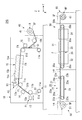
- FIG. 1 is a diagram illustrating an example of a manufacturing system SYS.
- the manufacturing system SYS shown in FIG. 1 manufactures a porous resin film F (porous imide resin film).
- the manufacturing system SYS includes a coating unit (coating apparatus) 10 that applies a predetermined coating solution to form an unfired film FA, a firing unit 20 that fires the unfired film FA to form a fired film FB, and a fired film.
- a removal unit 30 for removing fine particles from the FB to form a porous resin film F, and a control device (not shown) for comprehensively controlling each of the above units are provided.
- the manufacturing system SYS is configured, for example, in two upper and lower layers, the coating unit 10 is disposed on the second floor portion, and the baking unit 20 and the removal unit 30 are disposed on the first floor portion.
- the firing unit 20 and the removal unit 30 arranged on the same floor are arranged side by side in the Y direction, for example, but are not limited to this, for example, arranged in the X direction or the combined direction of the X direction and the Y direction. It may be arranged.
- the hierarchical structure of the manufacturing system SYS and the arrangement of each unit on each floor are not limited to the above.
- the coating unit 10 and the baking unit 20 are arranged on the second floor part, and the removal unit 30 is on the first floor part. It may be arranged. All units may be arranged on the same floor. In this case, each unit may be arranged in a row or in a plurality of rows. Further, all the units may be arranged on different levels.
- the unfired film FA is formed in a strip shape.
- a winding unit 40 that winds the belt-like unfired film FA into a roll is provided.
- a delivery unit 50 that feeds the roll-like unfired film FA toward the firing unit 20 is provided.
- a winding unit 60 that winds the porous resin film F into a roll is provided.
- the coating liquid used as the raw material of the porous resin film F contains a predetermined resin material, fine particles, and a solvent.
- the predetermined resin material include polyamic acid, polyimide, polyamideimide, and polyamide.
- the solvent an organic solvent capable of dissolving these resin materials is used.
- first coating liquid and second coating liquid two kinds of coating liquids having different fine particle contents are used as the coating liquid.
- first coating solution is prepared so that the content of fine particles is higher than that of the second coating solution.
- the first coating liquid contains a resin material and fine particles so as to have a volume ratio of 19:81 to 45:65.
- the second coating solution contains the resin material and the fine particles so as to have a volume ratio of 20:80 to 50:50.
- the volume ratio is set so that the fine particle content of the first coating liquid is higher than the fine particle content of the second coating liquid.
- the volume of each resin material a value obtained by multiplying the mass of each resin material by its specific gravity is used.
- the volume of the fine particles is 65 or more when the entire volume of the first coating liquid is 100, the particles are uniformly dispersed, and when the volume of the fine particles is within 81, the particles are aggregated. Disperse without doing. For this reason, holes can be formed uniformly in the porous resin film F. Moreover, if the volume ratio of the fine particles is within this range, the releasability when the unfired film FA is formed can be ensured.
- the volume of the fine particles is 50 or more when the total volume of the second coating liquid is 100, the fine particles are uniformly dispersed, and if the volume is within 80 of the fine particles, the fine particles are not aggregated, Moreover, since no cracks or the like are generated on the surface, the porous resin film F having good electric characteristics can be formed stably.
- the above-mentioned two types of coating solutions are prepared, for example, by mixing a solvent in which fine particles are dispersed in advance with polyamic acid, polyimide, polyamideimide or polyamide at an arbitrary ratio.
- it may be prepared by polymerizing polyamic acid, polyimide, polyamideimide or polyamide in a solvent in which fine particles are dispersed in advance.
- it can be produced by polymerizing tetracarboxylic dianhydride and diamine in an organic solvent in which fine particles are dispersed in advance to form a polyamic acid, or by further imidizing it into a polyimide.
- the final viscosity of the coating solution is preferably 300 to 2500 cP, more preferably 400 to 1500 cP, and even more preferably 600 to 1200 cP. If the viscosity of the coating solution is within this range, it is possible to form a film uniformly.
- the fine particle / polyimide ratio is 2 to 6 (mass ratio) when the fine particle material is an inorganic material described later.
- the fine particles and polyamic acid or polyimide may be mixed so as to be. More preferably, it is 3 to 5 (mass ratio).
- the fine particles and the polyamic acid or the polyimide may be mixed so that the fine particle / polyimide ratio is 1 to 3.5 (mass ratio). More preferably, the ratio is 1.2 to 3 (mass ratio).
- the fine particles and the polyamic acid or the polyimide are mixed so that the volume ratio of the fine particles / polyimide is 1.5 to 4.5 when the unfired film FA is formed. More preferably, it is 1.8 to 3 (volume ratio). If the fine particle / polyimide mass ratio or volume ratio is equal to or higher than the lower limit when the unfired film FA is used, pores having an appropriate density as a separator can be obtained. It is possible to form a film stably without causing problems such as cracks inside.
- the resin material is polyamide-imide or polyamide instead of polyamic acid or polyimide, the mass ratio is the same as above.
- polyamic acid used in the present embodiment one obtained by polymerizing an arbitrary tetracarboxylic dianhydride and diamine can be used without any particular limitation.
- the amount of tetracarboxylic dianhydride and diamine used is not particularly limited, but 0.50 to 1.50 mol of diamine is preferably used relative to 1 mol of tetracarboxylic dianhydride, and 0.60 to 1. It is more preferable to use 30 mol, and it is particularly preferable to use 0.70 to 1.20 mol.
- the tetracarboxylic dianhydride can be appropriately selected from tetracarboxylic dianhydrides conventionally used as raw materials for polyamic acid synthesis.
- the tetracarboxylic dianhydride may be an aromatic tetracarboxylic dianhydride or an aliphatic tetracarboxylic dianhydride. From the viewpoint of the heat resistance of the resulting polyimide resin, the aromatic tetracarboxylic dianhydride may be used. Preference is given to using carboxylic dianhydrides. Tetracarboxylic dianhydride may be used in combination of two or more.
- aromatic tetracarboxylic dianhydride examples include pyromellitic dianhydride, 1,1-bis (2,3-dicarboxyphenyl) ethane dianhydride, bis (2,3-dicarboxy Phenyl) methane dianhydride, bis (3,4-dicarboxyphenyl) methane dianhydride, 3,3 ′, 4,4′-biphenyltetracarboxylic dianhydride, 2,3,3 ′, 4′- Biphenyltetracarboxylic dianhydride, 2,2,6,6-biphenyltetracarboxylic dianhydride, 2,2-bis (3,4-dicarboxyphenyl) propane dianhydride, 2,2-bis (2 , 3-dicarboxyphenyl) propane dianhydride, 2,2-bis (3,4-dicarboxyphenyl) -1,1,1,3,3,3-hexafluoropropane dianhydride, 2,2
- Examples of the aliphatic tetracarboxylic dianhydride include ethylene tetracarboxylic dianhydride, butane tetracarboxylic dianhydride, cyclopentane tetracarboxylic dianhydride, cyclohexane tetracarboxylic dianhydride, 1, Examples include 2,4,5-cyclohexanetetracarboxylic dianhydride, 1,2,3,4-cyclohexanetetracarboxylic dianhydride, and the like. Among these, 3,3 ′, 4,4′-biphenyltetracarboxylic dianhydride and pyromellitic dianhydride are preferable from the viewpoints of price and availability. These tetracarboxylic dianhydrides may be used alone or in combination of two or more.
- the diamine can be appropriately selected from diamines conventionally used as a raw material for synthesizing polyamic acid.
- the diamine may be an aromatic diamine or an aliphatic diamine, but an aromatic diamine is preferred from the viewpoint of the heat resistance of the resulting polyimide resin. These diamines may be used in combination of two or more.
- aromatic diamines include diamino compounds in which one or about 2 to 10 phenyl groups are bonded. Specifically, phenylenediamine and derivatives thereof, diaminobiphenyl compounds and derivatives thereof, diaminodiphenyl compounds and derivatives thereof, diaminotriphenyl compounds and derivatives thereof, diaminonaphthalene and derivatives thereof, aminophenylaminoindane and derivatives thereof, diaminotetraphenyl Compounds and derivatives thereof, diaminohexaphenyl compounds and derivatives thereof, and cardo-type fluorenediamine derivatives.
- Phenylenediamine is m-phenylenediamine, p-phenylenediamine, etc., and phenylenediamine derivatives include diamines to which alkyl groups such as methyl group and ethyl group are bonded, such as 2,4-diaminotoluene, 2,4-triphenylene. Diamines and the like.
- the diaminobiphenyl compound is a compound in which two aminophenyl groups are bonded to each other.
- the diaminobiphenyl compound is a compound in which two aminophenyl groups are bonded to each other.
- the diaminodiphenyl compound is a compound in which two aminophenyl groups are bonded to each other via other groups.
- the bond is an ether bond, a sulfonyl bond, a thioether bond, a bond by alkylene or a derivative group thereof, an imino bond, an azo bond, a phosphine oxide bond, an amide bond, a ureylene bond, or the like.
- the alkylene bond has about 1 to 6 carbon atoms, and the derivative group has one or more hydrogen atoms in the alkylene group substituted with halogen atoms or the like.
- diaminodiphenyl compounds include 3,3′-diaminodiphenyl ether, 3,4′-diaminodiphenyl ether, 4,4′-diaminodiphenyl ether, 3,3′-diaminodiphenyl sulfone, 3,4′-diaminodiphenyl sulfone, 4,4'-diaminodiphenylsulfone, 3,3'-diaminodiphenylmethane, 3,4'-diaminodiphenylmethane, 4,4'-diaminodiphenylmethane, 4,4'-diaminodiphenyl sulfide, 3,3'-diaminodiphenyl ketone 3,4′-diaminodiphenyl ketone, 2,2-bis (p-aminophenyl) propane, 2,2′-bis (p-aminophenyl) hexafluor
- p-phenylenediamine p-phenylenediamine, m-phenylenediamine, 2,4-diaminotoluene, and 4,4'-diaminodiphenyl ether are preferable from the viewpoint of price and availability.
- the diaminotriphenyl compound is one in which two aminophenyl groups and one phenylene group are bonded via another group, and the other groups are the same as those of the diaminodiphenyl compound.
- Examples of diaminotriphenyl compounds include 1,3-bis (m-aminophenoxy) benzene, 1,3-bis (p-aminophenoxy) benzene, 1,4-bis (p-aminophenoxy) benzene, and the like. be able to.
- diaminonaphthalene examples include 1,5-diaminonaphthalene and 2,6-diaminonaphthalene.
- aminophenylaminoindane examples include 5 or 6-amino-1- (p-aminophenyl) -1,3,3-trimethylindane.
- diaminotetraphenyl compounds examples include 4,4′-bis (p-aminophenoxy) biphenyl, 2,2′-bis [p- (p′-aminophenoxy) phenyl] propane, 2,2′-bis [ and p- (p′-aminophenoxy) biphenyl] propane, 2,2′-bis [p- (m-aminophenoxy) phenyl] benzophenone, and the like.
- cardo-type fluorenediamine derivatives include 9,9-bisaniline fluorene.
- the aliphatic diamine preferably has about 2 to 15 carbon atoms, and specific examples include pentamethylene diamine, hexamethylene diamine, and heptamethylene diamine.
- a compound in which the hydrogen atom of these diamines is substituted with at least one substituent selected from the group such as a halogen atom, a methyl group, a methoxy group, a cyano group, and a phenyl group may be used.
- the means for producing the polyamic acid used in the present embodiment is not particularly limited, and for example, known methods such as a method of reacting an acid and a diamine component in an organic solvent can be used.
- the reaction between tetracarboxylic dianhydride and diamine is usually carried out in an organic solvent.
- the organic solvent used for the reaction of the tetracarboxylic dianhydride and the diamine is particularly capable of dissolving the tetracarboxylic dianhydride and the diamine and not reacting with the tetracarboxylic dianhydride and the diamine. It is not limited. An organic solvent can be used individually or in mixture of 2 or more types.
- organic solvents used in the reaction of tetracarboxylic dianhydride with diamine include N-methyl-2-pyrrolidone, N, N-dimethylacetamide, N, N-diethylacetamide, N, N-dimethylformamide, N Nitrogen-containing polar solvents such as N, diethylformamide, N-methylcaprolactam, N, N, N ′, N′-tetramethylurea; ⁇ -propiolactone, ⁇ -butyrolactone, ⁇ -valerolactone, ⁇ -valerolactone Lactone polar solvents such as ⁇ -caprolactone and ⁇ -caprolactone; dimethyl sulfoxide; acetonitrile; fatty acid esters such as ethyl lactate and butyl lactate; diethylene glycol dimethyl ether, diethylene glycol diethyl ether, dioxane, tetrahydrofuran, methyl cellosolve acetate,
- N-methyl-2-pyrrolidone N, N-dimethylacetamide, N, N-diethylacetamide, N, N-dimethylformamide, N, N- Nitrogen-containing polar solvents such as diethylformamide, N-methylcaprolactam, N, N, N ′, N′-tetramethylurea are preferred.
- the polymerization temperature is generally ⁇ 10 to 120 ° C., preferably 5 to 30 ° C.
- the polymerization time varies depending on the raw material composition used, but is usually 3 to 24 Hr (hour).
- the intrinsic viscosity of the polyamic acid organic solvent solution obtained under such conditions is preferably in the range of 1000 to 100,000 cP (centipoise), and more preferably in the range of 5,000 to 70,000 cP.
- the polyimide used in the present embodiment is not limited to its structure and molecular weight, and any known polyimide can be used as long as it is a soluble polyimide that can be dissolved in the organic solvent used in the coating solution.
- a polyimide you may have a functional group which accelerates
- a monomer to introduce a flexible bending structure into the main chain in order to obtain a polyimide soluble in an organic solvent for example, ethylenediamine, hexamethylenediamine, 1,4-diaminocyclohexane, 1,3-diaminocyclohexane, Aliphatic diamines such as 4,4′-diaminodicyclohexylmethane; 2-methyl-1,4-phenylenediamine, o-tolidine, m-tolidine, 3,3′-dimethoxybenzidine, 4,4′-diaminobenzanilide, etc.
- an organic solvent for example, ethylenediamine, hexamethylenediamine, 1,4-diaminocyclohexane, 1,3-diaminocyclohexane, Aliphatic diamines such as 4,4′-diaminodicyclohexylmethane; 2-methyl-1,4-phenylenediamine
- Aromatic diamines such as polyoxyethylene diamine, polyoxypropylene diamine and polyoxybutylene diamine; polysiloxane diamines; 2,3,3 ′, 4′-oxydiphthalic anhydride, 3,4,3 ′, 4′-oxydiphthalic anhydride, 2,2-bis (4- Hydroxyphenyl) propane dibenzoate-3,3 ', use of such 4,4'-tetracarboxylic dianhydride is valid.
- a monomer having a functional group that improves the solubility in an organic solvent for example, 2,2′-bis (trifluoromethyl) -4,4′-diaminobiphenyl, 2-trifluoromethyl-1,4 It is also effective to use a fluorinated diamine such as phenylenediamine.
- a monomer having a functional group that improves the solubility in an organic solvent for example, 2,2′-bis (trifluoromethyl) -4,4′-diaminobiphenyl, 2-trifluoromethyl-1,4
- a fluorinated diamine such as phenylenediamine.
- the same monomers as those described in the column for the polyamic acid can be used in combination as long as the solubility is not inhibited.
- polyimide which can be melt
- well-known methods such as the method of making a polyamic acid chemically imidate or heat imidize, and making it melt
- polyimide include aliphatic polyimide (total aliphatic polyimide), aromatic polyimide and the like, and aromatic polyimide is preferable.
- the aromatic polyimide is obtained by thermally or chemically obtaining a polyamic acid having a repeating unit represented by the formula (1) by a ring-closing reaction or by dissolving a polyimide having a repeating unit represented by the formula (2) in a solvent.
- Ar represents an aryl group.
- any known polyamideimide can be used as long as it is a soluble polyamideimide that can be dissolved in an organic solvent used in the coating solution, without being limited to its structure and molecular weight.
- the polyamideimide may have a functional group capable of condensing such as a carboxy group in the side chain or a functional group that promotes a crosslinking reaction or the like during firing.
- the polyamideimide used in the present embodiment is obtained by reacting any trimellitic anhydride and diisocyanate, or a precursor polymer obtained by reacting any reactive derivative of trimellitic anhydride with diamine. What is obtained by forming can be used without particular limitation.
- trimellitic anhydride and acid or a reactive derivative thereof examples include, for example, trimellitic anhydride halides such as trimellitic anhydride and trimellitic anhydride chloride, trimellitic anhydride ester, and the like.
- diisocyanate examples include metaphenylene diisocyanate, p-phenylene diisocyanate, 4,4′-oxybis (phenylisocyanate), 4,4′-diisocyanate diphenylmethane, bis [4- (4-isocyanatephenoxy) phenyl] sulfone, 2, And 2'-bis [4- (4-isocyanatophenoxy) phenyl] propane.
- diamine examples include those exemplified in the description of the polyamic acid.
- polyamide a polyamide obtained from a dicarboxylic acid and a diamine is preferable, and an aromatic polyamide is particularly preferable.
- Dicarboxylic acids include maleic acid, fumaric acid, itaconic acid, methylmaleic acid, dimethylmaleic acid, phenylmaleic acid, chloromaleic acid, dichloromaleic acid, fluoromaleic acid, phthalic acid, isophthalic acid, terephthalic acid, and diphenic acid Etc.
- diamine examples include those exemplified in the description of the polyamic acid.
- fine particles having a high sphericity and a small particle size distribution index are used. Such fine particles are excellent in dispersibility in a liquid and do not aggregate with each other.
- the particle diameter (average diameter) of the fine particles can be set to about 100 to 2000 nm, for example.
- the fine particle material is not particularly limited as long as it is a material that is insoluble in the solvent contained in the coating solution and can be removed from the porous resin film F in a later step. can do.
- the inorganic materials silica (silicon dioxide), metal oxides such as titanium oxide, alumina (Al 2 O 3) can be mentioned.
- organic materials include high molecular weight olefins (polypropylene, polyethylene, etc.), polystyrene, epoxy resin, cellulose, polyvinyl alcohol, polyvinyl butyral, polyester, polymethyl methacrylate, polyether, and other organic polymer fine particles.
- the fine particles include colloidal silica such as (monodispersed) spherical silica particles, calcium carbonate, and the like. In this case, the pore diameter of the porous resin film F can be made more uniform.
- the fine particles contained in the first coating solution and the fine particles contained in the second coating solution may have the same specifications such as the sphericity, particle size, material, or the like.
- the fine particles contained in the first coating solution preferably have a smaller or the same particle size distribution index as the fine particles contained in the second coating solution.
- the fine particles contained in the first coating solution preferably have a smaller particle diameter (average diameter) than the fine particles contained in the second coating solution.
- the fine particles contained in the first coating solution have a particle size of 100 to 1000 nm.
- the fine particles contained in the second coating solution are preferably 500 to 2000 nm (more preferably 700 to 2000 nm).
- the opening ratio of the pores on the surface of the porous resin film F can be made high and uniform.
- the strength of the film can be increased as compared with the case where the entire porous resin film F is made the particle size of the fine particles contained in the first coating liquid.
- the coating solution contains various additives such as a mold release agent, a dispersant, a condensing agent, an imidizing agent, and a surfactant as required in addition to a predetermined resin material, fine particles, and a solvent. May be.
- the coating unit 10 includes a transport unit 11, a first nozzle (first coating unit) 12, a second nozzle (second coating unit) 13, a drying unit 14, and a main heating unit (heating unit). ) 15, sub-heating part (heating part) 16, and peeling part 17.
- the transport unit 11 includes a belt-like base material (base material) S1, a base material feed roller 11a, a support roller (first roller) 11b, a support roller (second roller) 11c, a support roller 11d, and a base material winding.
- a take-up roller 11e and a carry-out roller 11f are provided.
- the strip base material S1 is formed in a strip shape.
- the belt-like substrate S1 is fed from the substrate feed roller 11a, is stretched around the support rollers 11b to 11d so as to have a tension, and is taken up by the substrate take-up roller 11e. Therefore, the lower surface S1b of the belt-like substrate S1 is guided by the support rollers 11b to 11d.
- the material of the band-shaped substrate S1 include polyethylene terephthalate (PET), but are not limited thereto, and may be a metal material such as stainless steel.
- the rollers 11a to 11f are formed in a cylindrical shape, for example, and are arranged in parallel to the X direction.
- Each of the rollers 11a to 11f is not limited to the arrangement parallel to the X direction, and at least one of the rollers 11a to 11f may be arranged to be inclined with respect to the X direction.
- the rollers 11a to 11f may be arranged in parallel to the Z direction so that the height positions in the Z direction are the same. In this case, the strip-shaped substrate S1 moves along the horizontal plane while standing with respect to the horizontal plane (XY plane).
- the base material feed roller 11a is arranged in a state where the belt-shaped base material S1 is wound.
- the support roller 11b is disposed on the + Z side of the base material feed roller 11a, and is disposed on the ⁇ Y side of the base material feed roller 11a.
- the support roller 11c is disposed on the + Z side of the support roller 11b, and is disposed on the + Y side of the support roller 11b.
- the support roller 11d is disposed on the + Y side of the support roller 11c, and is disposed on the ⁇ Z side of the support roller 11c.
- the belt-like substrate S1 is supported on the surface including the + Z side end portion of the support roller 11c by the arrangement of the three rollers of the support rollers 11b to 11d.
- the support roller 11d may be disposed at a height position substantially equal to the height position (position in the Z direction) of the support roller 11c.
- the strip-shaped substrate S1 is fed in the + Y direction from the support roller 11c toward the support roller 11d in a state substantially parallel to the XY plane.
- the substrate take-up roller 11e is disposed on the ⁇ Z side of the support roller 11d.
- the belt-like substrate S1 is fed in the ⁇ Z direction from the support roller 11d toward the substrate take-up roller 11e.
- the carry-out roller 11f is disposed on the + Y side and the ⁇ Z side of the support roller 11d.
- the carry-out roller 11f sends the unfired film FA formed by the main heating unit 15 in the + Y direction. This unfired film FA is carried out of the coating unit 10 by the carry-out roller 11f.
- the rollers 11a to 11f are not limited to a cylindrical shape, and a tapered crown may be formed. In this case, it is effective for correcting the deflection of the rollers 11a to 11f, and the belt-like base material S1 or an unfired film FA described later can contact the rollers 11a to 11f evenly. Further, radial crowns may be formed on the rollers 11a to 11f. In this case, it is effective for preventing meandering of the strip-shaped substrate S1 or the unfired film FA. Further, a concave crown (a portion where the central portion in the X direction is curved in a concave shape) may be formed on the rollers 11a to 11f.
- the following rollers may have a taper type, radial type, concave type crown or the like.
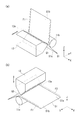
- FIG. 2A is a perspective view showing an example of the first nozzle 12.
- the first nozzle 12 forms a coating film (hereinafter, referred to as a first coating film F1) of the first coating liquid Q1 on the upper surface S1a of the strip-shaped substrate S1.
- the first nozzle 12 has a discharge port 12a that discharges the first coating liquid Q1.
- the discharge port 12a is formed, for example, such that the longitudinal direction is substantially the same as the dimension in the X direction of the strip-shaped substrate S1.
- the first nozzle 12 is disposed at the discharge position P1.
- the discharge position P1 is a position on the ⁇ Y direction with respect to the support roller 11b.
- the first nozzle 12 is disposed to be inclined such that the discharge port 12a faces the + Y direction. Accordingly, the discharge port 12a is directed to the portion of the belt-like substrate S1 that is supported at the ⁇ Y side end of the support roller 11b.
- the 1st nozzle 12 discharges the 1st coating liquid Q1 along the horizontal direction (Y direction) from the discharge port 12a with respect to the upper surface S1a of this strip
- the first nozzle 12 is formed to be movable in the Y direction, for example. For this reason, the first nozzle 12 is movable in the direction approaching (+ Y direction) and the direction separating ( ⁇ Y direction) from the strip-shaped substrate S1.
- the first nozzle 12 may be movable in the X direction or the Z direction.
- the first nozzle 12 may be provided so as to be rotatable around an axis parallel to the X direction.
- FIG. 2B is a perspective view showing an example of the second nozzle 13.
- the second nozzle 13 is formed on the belt-like substrate S1 so as to overlap the first coating film F1 and to apply a coating film (hereinafter referred to as a second coating film F2) of the second coating liquid Q2.
- the second nozzle 13 has a discharge port 13a for discharging the second coating liquid Q2.
- the discharge port 13a is formed, for example, so that the longitudinal direction is substantially the same as the dimension in the X direction of the strip-shaped substrate S1.
- the second nozzle 13 is disposed at the discharge position P2.
- the discharge position P2 is a position corresponding to the support roller 11c, and is a position in the + Z direction with respect to the support roller 11c.
- the second nozzle 13 is disposed such that the discharge port 13a faces the ⁇ Z direction. Accordingly, the discharge port 13a is directed to a portion of the belt-like substrate S1 that is supported by the + Z side end of the support roller 11c.
- the 2nd nozzle 13 discharges the 2nd coating liquid Q2 to the strip
- the second nozzle 13 is formed to be movable in the Z direction, for example. For this reason, the second nozzle 13 is movable in the direction approaching ( ⁇ Z direction) and the direction separating (+ Z direction) from the strip-shaped substrate S1.
- the second nozzle 13 may be movable in the X direction or the Y direction.
- the second nozzle 13 may be provided so as to be rotatable around an axis parallel to the X direction.
- the first nozzle 12 and the second nozzle 13 are arranged at a standby position (not shown) when the coating liquid is not discharged, and move from the standby position to the discharge positions P1 and P2 when discharging the coating liquid, respectively. It may be. Moreover, the part which performs the preliminary discharge operation
- movement of the 1st nozzle 12 and the 2nd nozzle 13 may be provided.
- the first nozzle 12 and the second nozzle 13 are each connected to a coating liquid supply source (not shown) via a connection pipe (not shown).
- the first nozzle 12 and the second nozzle 13 are provided with a holding unit (not shown) for holding a predetermined amount of coating liquid, for example.
- the first nozzle 12 and the second nozzle 13 may include a temperature adjustment unit that adjusts the temperature of the liquid material held in the holding unit.
- the coating amount of each coating liquid coated from the first nozzle 12 or the second nozzle 13 and the film thickness of the first coating film F1 or the second coating film F2 are determined by the nozzles, the connection pipes (not shown), or Adjustment is possible by the pressure of a pump (not shown) connected to a coating liquid supply source (not shown), the conveyance speed, the position of each nozzle or the distance between the belt-like substrate S1 and the nozzle.
- the film thickness of the first coating film F1 or the second coating film F2 is, for example, 0.5 ⁇ m to 500 ⁇ m, respectively.
- the film thickness of the first coating film F1 by the first coating liquid Q1 is, for example, 0. It is preferable to adjust in the range of 5 ⁇ m to 10 ⁇ m, and to adjust the film thickness of the second coating film F2 by the second coating liquid Q2 in the range of 1 ⁇ m to 50 ⁇ m, for example.
- the drying unit 14 is disposed between the first nozzle 12 and the second nozzle 13.
- the drying unit 14 dries the first coating film F1 formed on the strip-shaped substrate S1.
- the second coating film F2 after drying the first coating film F1, for example, it is possible to prevent the fine particles used in the second coating liquid from being mixed with the fine particles of the first coating film F1. Can do.
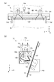
- FIGS. 3A and 3B are diagrams illustrating an example of the drying unit 14.
- the drying unit 14 includes a gas supply unit 14a, a gas ejection nozzle 14b, an exhaust frame 14c, and a mounting unit 14d.
- the gas supply unit 14a heats the gas to a predetermined temperature as necessary and supplies the gas to the gas ejection nozzle 14b.
- the gas supply unit 14a includes, for example, an infrared heater that heats a gas and a gas delivery unit that sends the heated gas.
- the gas heating temperature is, for example, in the range of 50 ° C. to 150 ° C., preferably 50 ° C. to 100 ° C.
- the gas may be ejected from the gas ejection nozzle 14b without heating.
- what is necessary is just to adjust suitably the flow volume of the gas supplied from the gas supply part 14a according to the conveyance speed of strip
- the gas ejection nozzle 14b ejects the gas supplied from the gas supply unit 14a toward the first coating film F1.
- the gas ejection nozzle 14b is formed long in the X direction.
- the gas ejection nozzle 14b has a connection part 14e.
- the connection portion 14e is provided on the end surface on the + Z side of the gas ejection nozzle 14b.
- the gas ejection nozzle 14b is connected to the gas supply part 14a via the connection part 14e.
- the gas ejection nozzle 14b has an ejection port 14f that ejects gas.
- the jet outlet 14f is formed in a slit shape.
- the longitudinal direction of the jet outlet 14f is the X direction.
- the gas ejection nozzle 14b has a long hollow portion in the X direction.
- the gas ejection nozzle 14b is formed so that the gas from the gas supply unit 14a spreads in the X direction and is ejected from the entire X direction of the ejection port 14f.
- the jet port 14f is formed so that the dimension in the longitudinal direction (X direction) is substantially equal to the width (dimension in the X direction) of the strip-shaped substrate S1.
- the dimension of the longitudinal direction of 14 f of jets may be formed larger than the width
- the gas ejection nozzle 14b is provided with an ejection adjustment plate 14g. The ejection adjusting plate 14g can adjust the opening width of the ejection port 14f.
- the exhaust frame 14c is arranged so as to surround the gas ejection nozzle 14b as shown in FIG.
- the exhaust frame 14c is disposed with a gap 14h between the gas ejection nozzle 14b.
- the exhaust frame 14c is fixed so as to be integrated with the gas ejection nozzle 14b in a state where a gap 14h is formed between the exhaust frame 14c and the gas ejection nozzle 14b.
- the exhaust frame 14c has an intake port 14i and an exhaust port 14j.
- the suction port 14i is directed to the first coating film F1 side (the band-shaped substrate S1 side).
- the suction port 14i and the exhaust port 14j communicate with each other through a gap 14h.
- the exhaust port 14j is formed on the end surface on the + Z side of the exhaust frame 14c.
- a plurality of exhaust ports 14j are arranged in the X direction. In this embodiment, the exhaust port 14j is provided in two places.
- An exhaust pipe is connected to the exhaust port 14j.
- a suction source such as a suction pump is connected to the exhaust pipe. By driving this suction source, the exhaust pipe becomes negative pressure.
- the gas on the surface of the first coating film F1 is sucked into the gap 14h from the suction port 14i. Further, the gas sucked into the gap 14h is exhausted from the exhaust port 14j through the exhaust pipe. For this reason, it can prevent that the gas ejected from the outlet 14f leaks out to the 1st nozzle 12 side or the 2nd nozzle 13 side, and can suppress that the discharge ports 12a and 13a dry.
- the mounting portion 14d is fixed to a frame (not shown). As shown in FIG. 3A, the attachment portion 14d is disposed so as to sandwich the belt-like substrate S1 in the X direction. For this reason, it has the structure which can prevent that the gas injected from 14 f of nozzles leaks out from a X direction.
- the main heating unit 15 is disposed on the + Y side of the second nozzle 13 and between the support roller 11c and the support roller 11d.
- the main heating unit 15 heats and dries the laminated body F3 of the first coating film F1 and the second coating film F2 applied on the strip-shaped substrate S1 to form an unfired film FA.
- the main heating unit 15 includes a chamber 15a and a heater 15b.
- the chamber 15a accommodates the strip-shaped substrate S1 and the heater 15b.
- the chamber 15a is disposed such that the + Y side end is inclined to the ⁇ Z side so as to be along the transport direction of the belt-like substrate S1.
- An exhaust duct 15c is provided in the chamber 15a.
- An exhaust pipe (not shown) is connected to the exhaust duct 15c. The gas in the chamber 15a is exhausted to the outside through the exhaust duct 15c and the exhaust pipe.
- the heater 15b heats the first coating film F1 and the second coating film F2.
- an infrared heater or the like is used as the heater 15b.
- the heater 15b heats the coating film at a temperature of about 30 ° C. to 100 ° C. Further, the heater 15b may be provided so as to perform heating while being divided into a plurality of regions in the Y direction.
- the sub-heating unit 16 heats the unsintered film FA so that the unsintered film FA formed by the main heating unit 15 can be easily separated from the strip-shaped substrate S1.
- the sub-heating unit 16 heats the gas to a predetermined temperature and sprays it on the unfired film FA.
- the heating temperature of the gas in the sub-heating unit 16 is set to a temperature at which the unfired film FA is easily peeled from the strip-shaped substrate S1.
- the sub-heating unit 16 exists independently from the main heating unit 15, but may be provided inside the main heating unit 15.
- the peeling part 17 is a part where the unfired film FA is peeled from the strip-shaped substrate S1.
- the unsintered film FA is peeled off manually by the operator, but the present invention is not limited to this, and it may be automatically performed using a manipulator or the like. Moreover, when peeling automatically, you may arrange
- the unsintered film FA peeled off from the strip-shaped substrate S1 is carried out of the coating unit 10 by the carry-out roller 11f and sent to the winding unit 40.
- the strip-shaped substrate S1 from which the unfired film FA has been peeled is wound up by the substrate winding roller 11e.
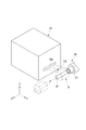
- FIG. 4 is a perspective view schematically showing a configuration on the + Y side of the coating unit 10. As shown in FIG. 4, on the + Y side of the coating unit 10, a carry-out port 10b for carrying out the unfired film FA is provided. The unsintered film FA carried out from the carry-out port 10 b is taken up by the take-up unit 40.
- the winding part 40 has a configuration in which a shaft member SF is mounted on a bearing 41.
- the shaft member SF forms the roll body R by winding up the unfired film FA carried out from the carry-out port 10b.
- the shaft member SF is provided so as to be detachable from the bearing 41.
- the shaft member SF is supported so as to be rotatable around an axis parallel to the X direction.
- the winding unit 40 has a drive mechanism (not shown) that rotates the shaft member SF attached to the bearing 41.
- the unsintered film FA is wound so that the surface of the unsintered film FA on the first coating film F1 side is disposed outside.
- the unfired film FA is wound up by rotating the shaft member SF counterclockwise in FIG. 1 by a drive mechanism.
- the shaft member SF By removing the shaft member SF from the bearing 41 in a state where the roll body R is formed, the roll body R can be moved to another unit.
- FIG. 5 is a perspective view schematically showing a configuration on the ⁇ Y side of the firing unit 20. As shown in FIG. 5, on the ⁇ Y side of the baking unit 20, a carry-in port 20a for carrying the unfired film FA is provided. The delivery unit 50 delivers the unsintered film FA to the carry-in port 20a.
- the delivery part 50 is configured such that the shaft member SF can be attached to the bearing 51.
- the shaft member SF can be used in common with that mounted on the bearing 41 of the winding unit 40. Therefore, the shaft member SF removed from the winding unit 40 can be mounted on the bearing 51 of the delivery unit 50. Thereby, the roll body R formed by the winding unit 40 can be disposed in the delivery unit 50.
- the bearing 41 and the bearing 41 of the winding-up part 40 although it can set so that the height from a floor surface may become equal, respectively, you may set to a different height position.
- the delivery unit 50 has a drive mechanism (not shown) that rotates the shaft member SF attached to the bearing 51.
- the unfired film FA constituting the roll body R is sent out toward the carry-in entrance 20a.
- the unfired film FA is wound so that the surface of the unfired film FA on the first coating film F1 side is disposed outside, the unfired film FA is formed from the roll body R. Is pulled out, the first coating film F1 side is arranged upward.
- the firing unit 20 is a unit that performs high-temperature processing on the unfired film FA.
- the firing unit 20 fires the unfired film FA to form a fired film FB containing fine particles.
- the firing unit 20 includes a chamber 21, a heating unit 22, and a transport unit 23.
- the chamber 21 has a carry-in port 20a for carrying in the unfired film FA and a carry-out port 20b for carrying out the fired film FB.
- the chamber 21 accommodates the heating unit 22 and the transfer unit 23.
- the heating unit 22 heats the unfired film FA carried into the chamber 31.
- the heating unit 22 includes a plurality of heaters 22a arranged side by side in the Y direction. For example, an infrared heater is used as the heater 22a.
- the heating unit 22 is disposed from the ⁇ Y side end to the + Y side end inside the chamber 21.
- the heating unit 22 can heat the unsintered film FA almost entirely in the Y direction.
- the heating unit 22 can heat the unfired film FA to about 120 ° C. to 450 ° C., for example.
- the heating temperature by the heating unit 22 is appropriately adjusted according to the conveyance speed of the unfired film FA, the constituent components of the unfired film FA, and the like.
- the transport unit 23 includes a transport belt 23a, a driving roller 23b, a driven roller 23c, and tension rollers 23d and 23e.
- the conveyor belt 23a is formed in an endless shape and is disposed along the Y direction.
- the conveyor belt 23a is formed using a material having durability against the firing temperature of the unfired film FA.
- the conveying belt 23a is stretched between the driving roller 23b and the driven roller 23c so as to be substantially parallel to the XY plane in a tensioned state.
- the unfired film FA and the fired film FB are transported in the + Y direction while being placed on the transport belt 23a.
- the driving roller 23b is arranged at the + Y side end inside the chamber 21.
- the drive roller 23b is formed in a cylindrical shape, for example, and is disposed in parallel with the X direction.
- the drive roller 23b is provided with a rotary drive device such as a motor.
- the driving roller 23b is provided so as to be rotatable around an axis parallel to the X direction by the rotation driving device.
- the conveying belt 23a rotates in the clockwise direction in FIG.
- the unfired film FA and the fired film FB placed on the transport belt 23a are transported in the + Y direction.
- the driven roller 23 c is disposed at the ⁇ Y side end inside the chamber 21.
- the driven roller 23c is formed in a cylindrical shape, for example, and is arranged in parallel with the X direction.
- the driven roller 23c is formed to have the same diameter as that of the driving roller 23b, and is disposed so that the position (height position) in the Z direction is substantially equal to that of the driving roller 23b.
- the driven roller 23c is provided to be rotatable around an axis parallel to the X direction. The driven roller 23c rotates following the rotation of the conveyor belt 23a.
- the tension roller 23d is disposed on the + Z side of the driven roller 23c.
- the tension roller 23d is arranged in parallel to the X direction and is provided to be rotatable around the X axis.
- the tension roller 23d is provided to be movable up and down in the Z direction.
- the tension roller 23d can sandwich the unfired film FA with the driven roller 23c.
- the tension roller 23d can rotate with the unfired film FA interposed therebetween.
- the tension roller 23e is disposed on the + Z side of the drive roller 23b.
- the tension roller 23e is disposed in parallel with the X direction, and is provided to be rotatable around the X axis.
- the tension roller 23e is provided to be movable up and down in the Z direction.
- the tension roller 23e can sandwich the fired film FB with the driving roller 23b.
- the tension roller 23e can rotate with the fired film FB interposed therebetween.
- the tension rollers 23d and 23e sandwich the unfired film FA and the fired film FB between the driven roller 23c and the drive roller 23b, respectively, so that the unrolled film FA and the fired film FB are sandwiched.
- the tension between the two places is cut from the external tension. Thereby, it is possible to prevent an excessive load from being applied to the unfired film FA and the fired film FB.
- the tension rollers 23d and 23e can be adjusted so that no tension is applied to the unfired film FA and the fired film FB disposed in the chamber 21.
- the removal unit 30 includes a chamber 31, an etching unit 32, a cleaning unit 33, a drying unit 34, and a transport unit 35.
- the chamber 31 has a carry-in port 30a for carrying in the fired film FB and a carry-out port 30b for carrying out the porous resin film F.
- the chamber 31 accommodates an etching unit 32, a cleaning unit 33, a drying unit 34, and a transport unit 35.
- the etching unit 32 performs etching on the fired film FB to remove fine particles contained in the fired film FB to form the porous resin film F.
- the etching unit 32 removes the fine particles by immersing the fired film FB in an etching solution capable of dissolving or decomposing the fine particles.
- the etching unit 32 is provided with a supply unit (not shown) that supplies such an etching solution and a storage unit that can store the etching solution.
- the cleaning unit 33 cleans the etched porous resin film F.
- the cleaning unit 33 is disposed on the + Y side of the etching unit 32 (in front of the transport direction of the porous resin film F).
- the cleaning unit 33 has a supply unit (not shown) for supplying a cleaning liquid. Moreover, you may have a collection
- the drying unit 34 dries the washed porous resin film F.
- the drying unit 34 is disposed on the + Y side of the cleaning unit 33 (in front of the transport direction of the porous resin film F).
- the drying unit 34 is provided with a heating unit for heating the porous resin film F and the like.
- the transport unit 35 transports the fired film FB and the porous resin film F across the etching unit 32, the cleaning unit 33, and the drying unit 34.
- the conveyance unit 35 includes a conveyance belt 35a, a driving roller 35b, and a driven roller 35c.
- a support roller that supports the conveyance belt 35a may be disposed inside the etching unit 32, the cleaning unit 33, and the drying unit 34.
- the conveyor belt 35a is formed in an endless shape and is disposed along the Y direction.
- the transport belt 35a is formed using a material having durability to the etching solution.
- the conveying belt 35a is stretched between the driving roller 35b and the driven roller 35c so as to be substantially parallel to the XY plane in a tensioned state.
- the fired film FB and the porous resin film F are placed on the transport belt 35a.
- the driving roller 35 b is disposed at the + Y side end inside the chamber 31.
- the drive roller 35b is formed in a cylindrical shape, for example, and is disposed in parallel with the X direction.
- the drive roller 35b is provided with a rotary drive device such as a motor.
- the driving roller 35b is provided so as to be rotatable around an axis parallel to the X direction by the rotation driving device.
- the conveying belt 35a rotates in the clockwise direction in FIG.
- the fired film FB and the porous resin film F placed on the transport belt 35a are transported in the + Y direction.
- the driven roller 35 c is disposed at the ⁇ Y side end inside the chamber 31.
- the driven roller 35c is formed in a cylindrical shape, for example, and is arranged in parallel to the X direction.
- the driven roller 35c is formed to have the same diameter as the driving roller 35b, and is disposed so that the position (height position) in the Z direction is substantially equal to the driving roller 35b.
- the driven roller 35c is provided to be rotatable around an axis parallel to the X direction. The driven roller 35c rotates following the rotation of the conveyor belt 35a.
- the removal unit 30 is not limited to removing fine particles by etching.
- an organic material that decomposes at a lower temperature than polyimide is used as the material of the fine particles
- the fine particles can be decomposed by heating the fired film FB.
- Such an organic material is not particularly limited as long as it decomposes at a lower temperature than polyimide.
- resin fine particles made of a linear polymer or a known depolymerizable polymer can be mentioned.
- a normal linear polymer is a polymer in which a polymer molecular chain is randomly cleaved during thermal decomposition
- a depolymerizable polymer is a polymer in which the polymer is decomposed into monomers during thermal decomposition.
- the decomposition temperature of the fine particles is preferably 200 to 320 ° C., more preferably 230 to 260 ° C.
- the decomposition temperature is 200 ° C. or higher, film formation can be performed even when a high boiling point solvent is used for the coating solution, and the range of selection of the baking conditions in the baking unit 20 is widened. If the decomposition temperature is less than 320 ° C., only the fine particles can be lost without causing thermal damage to the fired film FB.
- FIG. 6 is a perspective view schematically showing the configuration on the + Y side of the removal unit 30. As shown in FIG. 6, on the + Y side of the removal unit 30, a carry-out port 30 b for carrying out the porous resin film F is provided. The porous resin film F carried out from the carry-out port 30 b is taken up by the take-up unit 60.
- the winding unit 60 has a configuration in which a shaft member SF is mounted on a bearing 61.
- the shaft member SF winds up the porous resin film F carried out from the carry-out port 30b to form the roll body RF.
- the shaft member SF is provided so as to be detachable from the bearing 61.
- the shaft member SF is supported so as to be rotatable around an axis parallel to the X direction.
- the winding unit 60 has a drive mechanism (not shown) that rotates the shaft member SF attached to the bearing 61.
- the porous resin film F is wound up by rotating the shaft member SF by the drive mechanism.
- FIG. 7A to 7F are diagrams showing an example of the manufacturing process of the porous resin film F.
- an unfired film FA is formed in the coating unit 10.
- the base material feed roller 11a is rotated to send out the belt-like base material S1, and after the belt-like base material S1 is hung on the support rollers 11b to 11d, the base material take-up roller 11e takes up. Thereafter, the belt-like base material S1 is sequentially sent out from the base material feed roller 11a and is taken up by the base material take-up roller 11e.
- the strip-shaped substrate S1 is fed in a state where the lower surface S1b is guided by the support rollers 11b to 11d.
- the first nozzle 12 is disposed at the first position P1, and the discharge port 12a is directed in the + Y direction.
- the discharge port 12a is directed to the portion of the belt-like substrate S1 that is supported by the support roller 11b.
- the first coating liquid Q1 is discharged from the discharge port 12a.
- the first coating liquid Q1 is discharged from the discharge port 12a in the + Y direction, and after reaching the band-shaped substrate S1, is applied to the upper surface S1a of the band-shaped substrate S1 as the band-shaped substrate S1 moves.
- the first coating film F1 by the first coating liquid Q1 is formed on the upper surface S1a of the strip-shaped substrate S1.
- the resin material A1 contains fine particles A2 in a predetermined volume ratio.
- the first coating film F1 moves in the + Z direction with the movement of the strip-shaped substrate S1.
- a heating gas is ejected from the jet nozzle 14f of the gas ejection nozzle 14b, and the surface of the 1st coating film F1 is dried.
- an exhaust mechanism (not shown) connected to the exhaust port 14j, the heated gas sprayed to the first coating film F1 is exhausted through the suction port 14i, the gap 14h, and the exhaust port 14j. Thereby, it can prevent that heated gas leaks out to the 1st nozzle 12 side or the 2nd nozzle 13 side, and can suppress drying of the discharge ports 12a and 13a.
- the second nozzle 12 is arranged at the second position P2, and the discharge port 13a is directed in the ⁇ Z direction.
- the discharge port 13a is directed to the portion of the belt-like substrate S1 that is supported by the support roller 11c.
- the first coating film F1 reaches the ⁇ Z side of the discharge port 13a with the movement of the strip-shaped substrate S1
- the second coating liquid Q2 is discharged from the discharge port 13a.
- the second coating liquid Q2 is discharged in the ⁇ Z direction from the discharge port 13a, reaches the first coating film F1 formed on the band-shaped substrate S1, and then moves along with the movement of the band-shaped substrate S1. It is applied on the coating film F1.
- a second coating film F2 made of the second coating liquid is formed on the first coating film F1.
- the resin material A1 contains fine particles A2 at a predetermined volume ratio.
- the content ratio of the fine particles is set to be larger in the first coating film F1 than in the second coating film F2. Since the surface of the first coating film F1 is in a dried state by the drying unit 14, the first coating is hardly mixed with the second coating film F2 on the first coating film F1 and the like. The fine particle content of the film F1 and the second coating film F2 is maintained.
- the first coating liquid Q1 and the second coating liquid Q2 are applied with the discharge ports 12a and 13a facing the portions of the belt-like substrate S1 supported by the support rollers 11b and 11c, the first coating liquid The forces acting on the belt-like substrate S1 when the Q1 and the second coating liquid Q2 reach the belt-like substrate S1 are received by the support rollers 11b and 11c. For this reason, generation
- the first coating film F1 in the main heating unit 15 is transferred.
- the second coating film F2 is dried.
- the first coating film F1 and the second coating film F2 are heated using a heater 15b at a temperature of about 50 ° C. to 100 ° C., for example. If it is this temperature range, the 1st coating film F1 and the 2nd coating film F2 can be heated, without generating distortion, a deformation
- a heater 15b at a temperature of about 50 ° C. to 100 ° C., for example. If it is this temperature range, the 1st coating film F1 and the 2nd coating film F2 can be heated, without generating distortion, a deformation
- the unsintered film FA After the unsintered film FA is formed, when the unsintered film FA reaches the sub-heating unit 16 due to the movement of the strip-shaped substrate S1, the gas heated to a predetermined temperature is ejected from the sub-heating unit 16 to the unsintered film FA. The unfired film FA is heated. Thereby, the unsintered film FA is easily peeled from the strip-shaped substrate S1.
- the tip portion of the unfired film FA reaches the peeling portion 17
- the tip portion is peeled from the belt-like base material S1, for example, manually by the operator.
- PET is used as the material of the strip-shaped substrate S1
- the uncoated film FA is formed by drying the first coating film F1 and the second coating film F2
- the strip-shaped substrate S1 Since it becomes easy to peel off, the operator can easily peel off.
- the strip-shaped substrate S1 continues to move, and the first coating film F1 is formed by the first nozzle 12. Further, the second coating film F ⁇ b> 2 is subsequently formed by the second nozzle 13, and the unfired film FA is formed by the main heating unit 15. Thereby, the unsintered film FA is formed in a strip shape, and the length of the unsintered film FA carried out from the main heating unit 15 to the + Y side is gradually increased. The operator continues to peel off the unfired film FA at the peeling portion 17.
- the operator manually places the unfired film FA on the carry-out roller 11f and unfires the unfired film FA.
- the tip portion of the film FA is attached to the shaft member SF.
- the winding member 40 rotates the shaft member SF.
- the peeled unfired film FA is sequentially carried out of the coating unit 10 and wound up by the shaft member SF of the winding unit 40 to form the roll body R.
- the unfired film FA constituting the roll body R is peeled from the strip-shaped substrate S1, and both the front surface and the back surface are exposed.
- membrane FA the operation
- tip part to shaft member SF, etc. are not restricted to the aspect which an operator performs manually, For example, a manipulator, a member for peeling, etc. You may perform automatically using.
- a release layer may be formed on the surface of the strip-shaped substrate S1 in order to improve the peelability of the unfired film FA.
- the unfired film FA having a predetermined length is wound around the shaft member SF, the unfired film FA is cut, and the shaft member SF is removed from the bearing 41 together with the roll body R. Then, a new shaft member SF is mounted on the bearing 41 of the winding portion 40, and the cut end portion of the unfired film FA is attached to the shaft member SF and rotated to continuously form the unfired film FA.
- a simple roll body R can be created.
- the worker conveys the shaft member SF removed together with the roll body R from the bearing 41 to the delivery unit 50 and attaches it to the bearing 51.
- the conveying operation and mounting operation of the shaft member SF may be automatically performed using a manipulator, a conveying device, or the like.
- the unfired film FA is sequentially drawn from the roll body R by rotating the shaft member SF, and the unfired film FA is carried into the chamber 21 of the firing unit 20.
- an operator may perform manually and may perform automatically using a manipulator etc.
- the unsintered film FA carried into the chamber 21 is placed on the transport belt 23a and transported in the + Y direction according to the rotation of the transport belt 23a.
- the tension may be adjusted using the tension rollers 23d and 23e.
- the unfired film FA is baked using the heating unit 22 while the unfired film FA is conveyed.
- the temperature during firing varies depending on the structure of the unfired film FA, but is preferably about 120 ° C. to 375 ° C., more preferably 150 ° C. to 350 ° C. Moreover, when the organic material is contained in the fine particles, it is necessary to set the temperature lower than the thermal decomposition temperature. In the case where the coating solution contains polyamic acid, it is preferable to complete imidization in this baking.
- the unfired film FA is composed of polyimide, polyamideimide or polyamide, and the firing unit 20 applies the unfired film FA to the unfired film FA. This does not apply when high-temperature treatment is performed.
- the firing conditions include a method of raising the temperature from room temperature to 375 ° C. over 3 hours and then holding the temperature at 375 ° C. for 20 minutes, or from room temperature to 50 ° C. Stepwise heating may be performed such that the temperature is gradually raised to 375 ° C. in increments (each step is held for 20 minutes) and finally held at 375 ° C. for 20 minutes. Further, the end of the unfired film FA may be fixed to a SUS mold or the like to prevent deformation.
- a fired film FB is formed as shown in FIG.
- fine particles A2 are contained inside the resin layer A3 that has been imidized or subjected to high temperature treatment.
- the film thickness of the fired film FB can be obtained, for example, by measuring and averaging the thickness of a plurality of locations with a micrometer or the like.
- a preferable average film thickness is 3 ⁇ m to 500 ⁇ m, more preferably 5 ⁇ m to 100 ⁇ m, and still more preferably 10 ⁇ m to 30 ⁇ m when used for a separator or the like.
- the fired film FB formed in the firing unit 20 When the fired film FB formed in the firing unit 20 is unloaded from the firing unit 20, it is carried into the removal unit 30 without being wound up.
- an operator when carrying in the removal unit 30 the front-end
- the fired film FB carried into the removal unit 30 is placed on the transport belt 35a and transported in the + Y direction according to the rotation of the transport belt 35a.
- the fine particles A ⁇ b> 2 are first removed in the etching unit 32 as the fired film FB is conveyed.
- the fired film FB is immersed in an etching solution such as low-concentration hydrogen fluoride water.
- an etching solution such as low-concentration hydrogen fluoride water.
- the porous resin film F is sequentially carried into the cleaning unit 33 and the drying unit 34 according to the rotation of the transport belt 35a.
- the cleaning unit 33 the porous resin film F is cleaned by the cleaning liquid, and liquid draining is performed.
- the drying part 34 the porous resin film F after draining is heated, and the cleaning liquid is removed. Then, the porous resin film F is unloaded from the removal unit 30 and wound up by the shaft member SF of the winding unit 60.
- the coating unit 10 includes the first coating liquid Q1 including the strip-shaped substrate S1 that moves in a predetermined direction, the polyamic acid, polyimide, polyamideimide, or polyamide resin material A1 and the fine particles A2.
- a first nozzle 12 that is applied on the belt-like substrate S1 to form the first coating film F1, a resin material A1 and fine particles A2, and a second content of the fine particles A2 that is different from at least the first coating liquid Q1.
- the second nozzle 13 for forming the second coating film F2 by coating the coating liquid Q2 on the first coating film F1, and thus forming two layers with different contents of the fine particles A2 in the unfired film FA can do.
- the first coating film of the porous resin film F is formed.
- the pores of the porous portion are formed uniformly and densely with respect to the layer corresponding to the second coating film F2.
- the ions move smoothly by arranging the first coating film F1 side on the negative electrode surface side, thereby improving the electrical characteristics of the battery. Can be made.
- the strength as a film can be ensured as compared with the case where a porous imide resin film having the same porosity is formed only by the first coating liquid Q1.
- a high-quality porous resin film F can be obtained. it can.
- the manufacturing system SYS includes the coating unit 10, the formation of the unfired film FA, the firing of the unfired film FA (formation of the fired film FB), and the removal of the fine particles A2 (porous)
- the three steps of forming the conductive resin film F) can be performed in a series of flows. Thereby, the manufacturing efficiency of the porous resin film F can be improved.
- the strip-shaped substrate (S1) formed in a strip shape is used as the substrate, a strip-shaped unfired film (FA) can be formed. Therefore, it can be applied to a manufacturing process such as a roll-to-roll method, and a porous imide resin film (porous resin film F) can be efficiently formed.
- a first roller (support roller 11b) and a second roller (support roller 11c) for guiding the lower surface (S1b) of the belt-shaped substrate (S1) are provided, and the second application unit (second nozzle 13) is a second roller. Since the second liquid (second coating liquid Q2) reaches the belt-like base material, the force acting on the belt-like base material is received by the second roller because it is arranged corresponding to the roller. For this reason, generation
- first roller (support roller 11b) and the second roller (support roller 11c) are arranged at different positions in the vertical direction, and the first application unit (first nozzle 12) and the second application unit (second nozzle). 13) are arranged so that the respective coating directions cross each other, so that the first layer (first coating film F1) and the second layer (second coating film F2) are formed at different height positions. can do. Thereby, a 1st application part and a 2nd application part can be arrange
- Each of the first application part (first nozzle 12) and the second application part (second nozzle 13) is formed so as to be movable in the direction of approaching and separating from the base material (band-like base material S1). Therefore, the distances between the first application part and the second application part and the substrate can be adjusted.
- the heating part (15, 16) which heats the laminated body (F3) which consists of a 1st layer (1st nozzle 12) and 2nd layer (2nd nozzle 13) on a base material (band-shaped base material S1) is provided. Therefore, the unsintered film FA having two layers having different fine particle contents can be formed.
- the heating units (15, 16) include a main heating unit (15) for heating the stacked body (F3) and a sub-heating for heating the stacked body (unfired film FA) conveyed from the main heating unit to a predetermined temperature. Therefore, the unfired film FA can be efficiently formed and the unfired film FA can be easily peeled from the base material (band-like base material S1).
- the peeling (unfired film FA) composed of the first layer (first coating film F1) and the second layer (second coating film F2) on the base material (strip-shaped base material S1) is peeled off from the base material. Since the portion (17) is provided, the unfired film FA can be efficiently peeled off.
- FIGS. 8A and 8B are diagrams illustrating configuration examples of portions of the coating units 10A and 10B according to the modification.
- the discharge position P1A is set at a position shifted to the + Z side from the support roller 11b.
- the first nozzle 12 applies the first coating liquid Q1 in a state where the discharge port 12a is directed to a portion of the belt-like substrate S1 that is removed from the support of the support roller 11b (for example, a portion that is removed to the + Z side). To do.
- a protrusion When a foreign object is sandwiched between the lower surface S1b of the belt-like substrate S1 and the support roller 11b, a protrusion may be formed so that the belt-like substrate S1 side is raised. If the first coating liquid Q1 is applied to the portion where such protrusions are formed, a pinhole or the like may be formed in the first coating film F1. On the other hand, in this modification, a pinhole or the like is formed in the first coating film F1 by causing the first coating liquid Q1 to reach a portion of the strip-shaped substrate S1 that is not supported by the support roller 11b. Can be prevented.
- the coating unit 10B As shown in FIG. 8B, in the coating unit 10B, another support roller 11g is disposed between the support roller 11b and the support roller 11c, and the belt-like substrate S1 is provided with the support roller 11b, the support roller 11g, It is in a state of being guided by the support roller 11c.
- the discharge position P1B is set at a position shifted to the + Z side from the support roller 11b.
- the first nozzle 12 discharges the first coating liquid Q1 with the discharge port 12a facing the portion of the strip-shaped substrate S1 that is supported by the support roller 11b and the support roller 11g. Thereby, it can prevent that a pinhole etc. are formed in the 1st coating film F1 similarly to the above.
- FIG. 9 is a diagram illustrating an example of the coating unit 210 according to the second embodiment.
- the configuration in which the belt-shaped substrate S1 formed of a resin material such as PET is used as a substrate is described as an example.
- the material of the belt-shaped substrate is the same as that of the first embodiment. Is different.
- the difference from the first embodiment will be mainly described.
- a strip-shaped substrate S2 formed of a metal material such as stainless steel is used as the substrate.
- the strip-shaped substrate S2 is formed in an endless shape, and is stretched between the support roller 211a, the support rollers 11b, 11c, and 11d, and the support roller 211e so as to have a tension. Therefore, the lower surface S2b of the strip-shaped substrate S2 is guided by the support rollers 211a, 11b, 11c, 11d, and 211e.
- Each strip-shaped substrate S2 circulates between the support rollers 211a, 11b, 11c, 11d, and 211e, for example, in the clockwise direction of FIG.
- first nozzle 12 forms the first coating film F1 on the upper surface S2a of the strip-shaped substrate S2.
- second nozzle 13 forms a second coating film F2 on the upper surface S2a of the strip-shaped substrate S2 so as to overlap the first coating film F1.
- the laminated body F3 formed on the strip-shaped substrate S2 is heated. Since the strip-shaped substrate S2 is formed of a metal material, the heating temperature in the main heating unit 15 can be set higher than when a substrate formed of a resin material is used. For this reason, since it can heat in high temperature and a short time, the unbaking film
- the upper surface S2a of the strip-shaped substrate S2 is formed, for example, as a mirror surface so that the formed unfired film FA can be easily peeled off. Note that a release layer may be formed in advance on the upper surface S2a with a release agent or the like.
- a cleaning section 212 is disposed between the support roller 211e and the support roller 211a.
- the cleaning unit 212 cleans the strip-shaped substrate S2 after the unfired film FA is peeled off.
- the cleaning unit 212 includes a removing unit that removes foreign matter on the upper surface S2a of the strip-shaped substrate S2.
- cleaning part 212 may have a structure which has static elimination parts, such as an ionizer, and can neutralize strip
- the strip-shaped substrate (S2) is formed endlessly and circulates, the material for forming the strip-shaped substrate can be saved, and the cost can be reduced.
- the belt-like base material (S2) is formed of a metal material, wrinkles and the like are hardly formed compared to the case where the belt-like base material is formed of a resin material, and the structure has excellent durability. Thereby, the unfired film FA can be stably formed.
- FIG. 10 is a diagram illustrating an example of the coating unit 310 according to the third embodiment.
- belt-shaped base material S1 differs from 1st Embodiment.
- the difference from the first embodiment will be mainly described.
- the transport unit 311 includes a belt-like base material (base material) S1, a base material feed roller 11a, a support roller (first roller) 11b, and a support roller (first roller). 2 rollers) 11c, a support roller 11d, a substrate take-up roller 11e, and a carry-out roller 11f.
- the transport unit 311 includes a transport member S3 and support rollers 311a and 311e.
- the conveying member S3 is formed in a strip shape, and is formed in an endless shape using a metal material such as stainless steel, for example.
- the conveying member S3 is stretched between the support roller 311a, the support rollers 11b, 11c, and 11d, and the support roller 311e so as to have tension. Therefore, the lower surface of the conveying member S3 is guided by the support rollers 311a, 11b, 11c, 11d, and 311e.
- the conveying member S3 circulates between these support rollers 311a, 11b, 11c, 11d, and 311e, for example, in the clockwise direction of FIG.
- the strip base material S1 is formed in a strip shape.
- the belt-like base material S1 is fed from the base material feed roller 11a, is stretched over the conveying member S3 so as to have a tension, and is taken up by the base material take-up roller 11e. Therefore, the lower surface S1b of the strip-shaped substrate S1 is guided by the transport member S3.
- the first nozzle 12 forms the first coating film F1 on the upper surface S1a of the strip-shaped substrate S1 supported by the transport member S3.
- the second nozzle 13 forms a second coating film F2 on the upper surface S1a of the belt-like substrate S1 supported by the transport member S3 so as to overlap the first coating film F1. For this reason, the 1st coating film F1 and the 2nd coating film F2 can be formed stably.
- the laminated body F3 formed on the strip-shaped substrate S1 is heated. Since this belt-like base material S1 is arranged on the conveying member S3, it is less likely to be wrinkled or the like and has excellent durability compared to the case where the belt-like base material S1 is used alone. Moreover, since strip
- the peeling part 17 the unsintered film FA formed on the strip-shaped substrate S1 is peeled off. Therefore, the peeling can be easily performed as compared with the case where the unfired film FA formed on the band-shaped base material of the metal material is peeled off.
- cleaning part 312 is arrange
- the cleaning unit 312 cleans the transport member S3.
- the cleaning unit 312 has a removing unit that removes foreign matter on the upper surface S3a of the conveying member S3. Thereby, since it can prevent that a foreign material is pinched between conveyance member S3 and strip
- cleaning part 312 may have a structure which has static elimination parts, such as an ionizer, and can neutralize conveyance member S3.
- the belt-like base material (S1) formed in a belt shape is used as the base material, and at least the first application part (first nozzle 12) and the second application part (second nozzle). 13) includes a transport member (S3) that transports the belt-shaped substrate in a range corresponding to 13), and the transport member is formed in a belt-like and endless shape and circulates. Therefore, the first layer (first coating film F1) and the second layer The layer (second coating film F2) can be formed stably. Moreover, since the conveyance member (S3) is formed of a metal material, wrinkles and the like are hardly formed on the belt-like base material S1, and the structure has excellent durability.
- FIG. 11 is a diagram illustrating a configuration example of a part of a coating unit 310A according to a modification.
- an auxiliary roller 11h is provided between the support roller 11b and the support roller 11c.
- the auxiliary roller 11h is disposed between the belt-like base material S1 and the conveying member S3, and supports the belt-like base material S1 in a tensioned state.
- the auxiliary roller 11h is provided in non-contact with the conveying member S3. Therefore, the belt-like substrate S1 is transported between the support roller 11b and the support roller 11c in a state of being separated from the transport member S3.
- the first nozzle 12 applies the first coating liquid Q1 in a state where the discharge port 12a is directed to a portion of the belt-like substrate S1 that is removed from the support of the support roller 11b (for example, a portion that is removed to the + Z side). .
- the discharge port 12a is directed to a portion of the belt-like substrate S1 that is removed from the support of the support roller 11b (for example, a portion that is removed to the + Z side).
- the drying unit 14 is disposed, for example, between the support roller 11b and the auxiliary roller 11h, but is not limited thereto, and may be disposed corresponding to the auxiliary roller 11h. You may arrange
- FIG. 12 is a diagram illustrating an example of the coating unit 410 according to the fourth embodiment.
- the present embodiment is different from the first embodiment in that a winding device for winding the unsintered film FA is provided in the coating unit 410.
- the difference from the first embodiment will be mainly described.
- the coating unit 410 is provided with a winding unit (roll body holding unit) 440.
- the winding unit 440 winds the unsintered film FA peeled off from the strip-shaped substrate S1 and sent by the support roller 11i.
- the configuration of the winding unit 440 is substantially the same as the configuration of the winding unit 40 of the first embodiment.
- the winding unit 440 has a configuration in which the shaft member SF is mounted on the bearing 441.
- the shaft member SF forms the roll body R by winding the unfired film FA sent by the support roller 11i.
- the shaft member SF is detachably attached to the bearing 441.
- the winding unit 440 has a drive mechanism (not shown) that rotates the shaft member SF attached to the bearing 41.
- the unsintered film FA is wound so that the surface of the unsintered film FA on the first coating film F1 side is disposed outside.
- the unfired film FA is wound up by rotating the shaft member SF counterclockwise in FIG. 18 by the drive mechanism.
- the roll body R By removing the shaft member SF from the bearing 441 in a state where the roll body R is formed, the roll body R can be moved to another unit.
- the strip-shaped substrate S1 from which the unfired film FA has been peeled is wound up by a substrate winding roller (winding portion) 11e.
- the roll body holding part (winding part 440) that holds the roll body (R) of the belt-like base material (S1) and the belt-like base material drawn from the roll body are wound up.
- the roll body can be applied to a manufacturing process such as a roll-to-roll system, and an efficient porous imide resin film (porous resin).
- a film F) can be formed.
- belt-shaped base material can be collect
- the winding device 90 includes a frame 91, a shaft member SF, a bearing 92, a drive unit 93, relay rollers 94a to 94e, and a roller support unit 95.
- the frame 91 supports the shaft member SF, the bearing 92, the drive unit 93, the relay rollers 94a to 94e, and the roller support unit 95.
- the shaft member SF forms the roll body R by winding up the unfired film FA carried out from the coating unit 10.
- the shaft member SF is detachably attached to the bearing 92.
- the shaft member SF is supported by the bearing 92 so as to be rotatable around an axis parallel to the X direction.
- the relay rollers 94a to 94e send the unfired film FA to the shaft member SF while adjusting the tension of the unfired film FA.
- the relay rollers 94a to 94e are formed in a cylindrical shape, for example, and are arranged parallel to the X direction.
- the unsintered film FA is bridged in the order of the relay rollers 94a, 94b, 94c, 94d, and 94e, but is not limited to this, and some relay rollers may not be used.
- at least one of the relay rollers 94 a to 94 e may be movable by the roller support portion 95.
- the roller support part 95 may be able to move the relay roller 94b in the Z direction or the Y direction.
- the structure which rotates the relay roller 94b around the axis line AX parallel to an X-axis by the roller support part 95 may be sufficient.
- the load on the relay roller 94b may be changed by moving a movable weight (not shown) located on the ⁇ Y side of the relay roller 94b and arranged via a fulcrum shaft. In this case, it is possible to adjust the tension of the unfired film FA by adjusting the load applied to the relay roller 94b with the weight.
- the relay rollers 94a to 94e are not limited to being arranged parallel to the X direction, and may be arranged inclined with respect to the X direction. Further, the relay rollers R21 to R25 are not limited to a cylindrical shape, and may be a taper type, a radial type, a concave type or the like on which a crown is formed.
- the above-described winding device 90 may be used in place of the winding unit 60. Further, the film such as the unfired film FA can be sent out by rotating the shaft member SF in the direction opposite to the case of winding the film such as the unfired film FA. For this reason, it is also possible to use the winding device 90 instead of the above-mentioned delivery part 50, for example.
- FIG. 14 is a schematic view showing an example of the lithium ion battery 200, and shows a state in which a part thereof is cut open.
- the lithium ion battery 200 includes a metal case 201 that also serves as a positive electrode terminal, and a negative electrode terminal 202. Inside the metal case 201, a positive electrode 201a, a negative electrode 202a, and a separator 100 are provided and are immersed in an electrolyte solution (not shown). The separator 100 is disposed between the positive electrode 201a and the negative electrode 202a, and prevents electrical contact between the positive electrode 201a and the negative electrode 202a.
- the positive electrode 201a a lithium transition metal oxide is used, and as the negative electrode 202a, for example, lithium, carbon (graphite), or the like is used.
- the porous resin film F described in the above embodiment is used as the separator 100 of the lithium ion battery 200.
- the separator 100 of the square lithium ion battery 200 is described as an example, but the present invention is not limited to this.
- the porous resin film F can be used for any type of lithium ion battery separator such as a cylindrical type or a laminate type.
- the porous resin film F can be used as a fuel cell electrolyte membrane, a gas or liquid separation membrane, and a low dielectric constant material.
- the present invention is not limited to the above description, and various modifications can be made without departing from the gist of the present invention.
- the configuration in which the unfired film FA is peeled from the strip-shaped substrate S1 in the peeling portion 17 provided inside the coating unit 10 has been described as an example, but the present invention is not limited thereto.
- the unfired film FA and the strip-shaped substrate S1 are wound together without being peeled off in the coating unit 10, and the unfired film FA is removed from the strip-shaped substrate S1 while being immersed in a liquid such as water outside the coating unit 10. It may be peeled off.
- the mode in which the unfired film FA is immersed in the liquid is not limited to the case where the unfired film FA is peeled off from the strip-shaped substrate S1.
- a means for forcing there is a step of pressing the unfired film FA. Thereby, it is possible to suppress the formation of wrinkles when the unfired film FA is dried or fired.
- the application unit 10 is the conveyance part 11, the 1st nozzle (1st application part) 12, the 2nd nozzle (2nd application part) 13, the drying part 14, and the main part. It has been described that the heating unit (heating unit) 15, the sub-heating unit (heating unit) 16, and the peeling unit 17 are included. Of these, the configuration excluding the sub-heating unit (heating unit) 16. It may be. Moreover, although the said embodiment and modification demonstrated and demonstrated as an example the case where three processes of application
- a production system for producing a porous imide resin film is a coating system in which a liquid containing polyamic acid, polyimide, polyamideimide or polyamide and fine particles is applied to a substrate to form an unfired film. It can be set as the manufacturing system containing a unit and the removal unit which removes the said microparticles
- the configuration in which the porous resin film F is formed by the so-called roll-to-roll method has been described as an example, but the present invention is not limited to this.
- the porous resin film F is unloaded from the removal unit 30 after the processing in the removal unit 30 is finished, the porous resin film F is cut by a predetermined length without being wound by the winding unit 60, It may be recovered.
Landscapes
- Chemical & Material Sciences (AREA)
- Chemical Kinetics & Catalysis (AREA)
- Engineering & Computer Science (AREA)
- Electrochemistry (AREA)
- General Chemical & Material Sciences (AREA)
- Manufacturing & Machinery (AREA)
- Life Sciences & Earth Sciences (AREA)
- Wood Science & Technology (AREA)
- Inorganic Chemistry (AREA)
- Materials Engineering (AREA)
- Health & Medical Sciences (AREA)
- Medicinal Chemistry (AREA)
- Polymers & Plastics (AREA)
- Organic Chemistry (AREA)
- Cell Separators (AREA)
- Coating Apparatus (AREA)
- Manufacture Of Porous Articles, And Recovery And Treatment Of Waste Products (AREA)
- Application Of Or Painting With Fluid Materials (AREA)
- Battery Electrode And Active Subsutance (AREA)
Abstract
Description
ここで、各ユニットを説明する前に、多孔性樹脂膜Fの原料となる塗布液について説明する。塗布液は、所定の樹脂材料と、微粒子と、溶剤とを含む。所定の樹脂材料としては、例えばポリアミド酸、ポリイミド、ポリアミドイミド、又はポリアミドが挙げられる。溶剤としては、これらの樹脂材料を溶解可能な有機溶剤が用いられる。
<ポリアミド酸>
本実施形態で用いるポリアミド酸は、任意のテトラカルボン酸二無水物とジアミンを重合して得られるものが、特に限定されることなく使用できる。テトラカルボン酸二無水物及びジアミンの使用量は特に限定されないが、テトラカルボン酸二無水物1モルに対して、ジアミンを0.50~1.50モル用いるのが好ましく、0.60~1.30モル用いるのがより好ましく、0.70~1.20モル用いるのが特に好ましい。
本実施形態に用いるポリイミドは、塗布液に使用する有機溶剤に溶解可能な可溶性ポリイミドなら、その構造や分子量に限定されることなく、公知のものが使用できる。ポリイミドについて、側鎖にカルボキシ基等の縮合可能な官能基又は焼成時に架橋反応等を促進させる官能基を有していてもよい。


本実施形態に用いるポリアミドイミドは、塗布液に使用する有機溶剤に溶解可能な可溶性ポリアミドイミドなら、その構造や分子量に限定されることなく、公知のものが使用できる。ポリアミドイミドについて、側鎖にカルボキシ基等の縮合可能な官能基又は焼成時に架橋反応等を促進させる官能基を有していてもよい。
ポリアミドとしては、ジカルボン酸とジアミンとから得られるポリアミドが好ましく、特に芳香族ポリアミドが好ましい。
続いて、微粒子について説明する。微粒子は、例えば真球率が高く、粒径分布指数の小さいものが用いられる。このような微粒子は、液体中での分散性に優れ、互いに凝集しない状態となる。微粒子の粒径(平均直径)としては、例えば、100~2000nm程度に設定することができる。上記のような微粒子を用いることにより、後の工程で微粒子を除去することで得られる多孔性樹脂膜Fの孔径を揃えることができる。このため、多孔性樹脂膜Fによって形成されるセパレータに印加される電界を均一化できる。
本実施形態に係る塗布ユニット10は、搬送部11と、第1ノズル(第1塗布部)12と、第2ノズル(第2塗布部)13と、乾燥部14と、主加熱部(加熱部)15と、副加熱部(加熱部)16と、剥離部17とを有する。
搬送部11は、帯状基材(基材)S1と、基材送出ローラ11aと、支持ローラ(第1ローラ)11bと、支持ローラ(第2ローラ)11cと、支持ローラ11dと、基材巻取ローラ11eと、搬出ローラ11fとを有する。
図4は、塗布ユニット10の+Y側の構成を概略的に示す斜視図である。
図4に示すように、塗布ユニット10の+Y側には、未焼成膜FAを搬出する搬出口10bが設けられている。搬出口10bから搬出された未焼成膜FAは、巻き取り部40によって巻き取られる。
図5は、焼成ユニット20の-Y側の構成を概略的に示す斜視図である。
図5に示すように、焼成ユニット20の-Y側には、未焼成膜FAを搬入する搬入口20aが設けられている。送り出し部50は、搬入口20aに対して未焼成膜FAを送り出す。
焼成ユニット20は、本実施形態において、未焼成膜FAに対する高温処理を行うユニットである。焼成ユニット20は、未焼成膜FAを焼成し、微粒子を含んだ焼成膜FBを形成する。焼成ユニット20は、チャンバー21と、加熱部22と、搬送部23とを有する。チャンバー21は、未焼成膜FAを搬入する搬入口20aと、焼成膜FBを搬出する搬出口20bとを有している。チャンバー21は、加熱部22及び搬送部23を収容する。
除去ユニット30は、チャンバー31と、エッチング部32と、洗浄部33と、乾燥部34と、搬送部35と、を有する。チャンバー31は、焼成膜FBを搬入する搬入口30aと、多孔性樹脂膜Fを搬出する搬出口30bとを有している。チャンバー31は、エッチング部32、洗浄部33、乾燥部34及び搬送部35を収容する。
図6は、除去ユニット30の+Y側の構成を概略的に示す斜視図である。
図6に示すように、除去ユニット30の+Y側には、多孔性樹脂膜Fを搬出する搬出口30bが設けられている。搬出口30bから搬出された多孔性樹脂膜Fは、巻き取り部60によって巻き取られる。
次に、上記のように構成された製造システムSYSを用いて多孔性樹脂膜Fを製造する動作の一例を説明する。図7(a)~(f)は、多孔性樹脂膜Fの製造過程の一例を示す図である。
上記第1実施形態では、第1ノズル12について、帯状基材S1のうち支持ローラ11bによって支持される部分に吐出口12aを向けた状態で第1塗布液Q1を塗布する場合を例に挙げて説明したが、これに限定するものではない。
図8(a)に示すように、塗布ユニット10Aでは、支持ローラ11bから+Z側にずれた位置に吐出位置P1Aが設定されている。この場合、第1ノズル12は、帯状基材S1のうち支持ローラ11bの支持から外れた部分(例えば、+Z側に外れた部分)に吐出口12aを向けた状態で第1塗布液Q1を塗布する。帯状基材S1の下面S1bと支持ローラ11bとの間に異物が挟まる場合、帯状基材S1側が盛り上がるように突起が形成される場合がある。このような突起が形成された部分に第1塗布液Q1を塗布すると、第1塗布膜F1にピンホール等が形成されるおそれがある。これに対して、本変形例では、帯状基材S1のうち支持ローラ11bの支持から外れた部分に第1塗布液Q1を到達させることにより、第1塗布膜F1にピンホール等が形成されるのを防ぐことができる。
次に、第2実施形態を説明する。図9は、第2実施形態に係る塗布ユニット210の一例を示す図である。上記実施形態では、基材としてPET等の樹脂材料によって形成された帯状基材S1が用いられる構成を例に挙げて説明したが、本実施形態では帯状基材の材料等が第1実施形態とは異なっている。以下、第1実施形態との相違点を中心に説明する。
次に、第3実施形態を説明する。図10は、第3実施形態に係る塗布ユニット310の一例を示す図である。本実施形態では、帯状基材S1を搬送する搬送部311の構成が第1実施形態とは異なっている。以下、第1実施形態との相違点を中心に説明する。
上記第3実施形態では、支持ローラ11bから支持ローラ11cにかけて、帯状基材S1が搬送部材S3上に支持された状態で搬送される場合を例に挙げて説明したが、これに限定するものではない。
図11に示すように、支持ローラ11bと支持ローラ11cとの間には、補助ローラ11hが設けられている。この補助ローラ11hは、帯状基材S1と搬送部材S3との間に配置され、帯状基材S1をテンションが掛かった状態で支持する。補助ローラ11hは、搬送部材S3とは非接触に設けられる。したがって、支持ローラ11bと支持ローラ11cとの間では、帯状基材S1が搬送部材S3から離れた状態で搬送される。
次に、第4実施形態を説明する。図12は、第4実施形態に係る塗布ユニット410の一例を示す図である。本実施形態では、未焼成膜FAを巻き取るための巻き取り装置が塗布ユニット410に設けられる点で第1実施形態とは異なっている。以下、第1実施形態との相違点を中心に説明する。
上記実施形態では、巻き取り部40、60、440として、軸部材SFを軸受41、61、441に着脱させる構成を例に挙げて説明したが、これに限定するものではなく、例えば図13に示すような巻き取り装置90が用いられてもよい。以下、巻き取り部40に代えて巻き取り装置90が用いられる場合を例に挙げて説明する。
次に、実施形態に係るセパレータ100を説明する。図14は、リチウムイオン電池200の一例を示す模式図であり、一部が切り開かれた状態を示している。図14に示すように、リチウムイオン電池200は、正極端子を兼ねた金属ケース201と、負極端子202とを有している。金属ケース201の内部には、正極201aと、負極202aと、セパレータ100とが設けられており、不図示の電解液に浸されている。セパレータ100は、正極201aと負極202aとの間に配置され、正極201aと負極202aとの間の電気的接触を防いでいる。正極201aとしては、リチウム遷移金属酸化物が用いられ、負極202aとしては、例えばリチウムやカーボン(グラファイト)等が用いられている。
例えば、上記実施形態では、塗布ユニット10の内部に設けられる剥離部17において未焼成膜FAを帯状基材S1から剥離する構成を例に挙げて説明したが、これに限定するものではない。例えば、塗布ユニット10において未焼成膜FAと帯状基材S1とを剥離せずに一体で巻き取り、塗布ユニット10の外部で水などの液体中に浸しながら未焼成膜FAを帯状基材S1から剥離してもよい。
また、上記実施形態及び変形例では、塗布ユニット10における塗布、焼成ユニット20における焼成、除去ユニット30における除去、の3つの工程を行う場合を例に挙げて説明したが、これに限定するものではない。例えば、塗布膜の材料としてポリイミド、ポリアミドイミド、又はポリアミドが用いられる場合、焼成を行わなくてもよい。このため、焼成を行わない場合、例えば焼成ユニット20と除去ユニット30との間に巻き取り装置及び送り出し装置等を設けることにより、塗布ユニット10で形成された未焼成膜FAを、焼成ユニット20を介することなく、除去ユニット30に搬入させることが可能となる。また、焼成を行わない場合、多孔性のイミド系樹脂膜を製造する製造システムは、ポリアミド酸、ポリイミド、ポリアミドイミド又はポリアミド及び微粒子を含む液体を基材に塗布して未焼成膜を形成する塗布ユニットと、前記塗布ユニット内又は前記塗布ユニット外で前記基材から剥離した前記未焼成膜から前記微粒子を除去する除去ユニットとを含む製造システムとすることができる。
Claims (14)
- 多孔性のイミド系樹脂膜を形成するための塗布装置であって、
所定方向に移動する基材と、
ポリアミド酸、ポリイミド、ポリアミドイミド又はポリアミド、及び微粒子を含む第1液体を前記基材上に塗布して第1層を形成する第1塗布部と、
ポリアミド酸、ポリイミド、ポリアミドイミド又はポリアミド、及び微粒子を含み、少なくとも前記第1液体に対して微粒子の含有率が異なる第2液体を前記第1層上に塗布して第2層を形成する第2塗布部と、を備える塗布装置。 - 前記基材として、帯状に形成された帯状基材が用いられる請求項1記載の塗布装置。
- 前記帯状基材の下面を案内する第1ローラ及び第2ローラを備え、
前記第2塗布部は、前記第2ローラに対応して配置される請求項2に記載の塗布装置。 - 前記第1ローラ及び前記第2ローラは、上下方向の位置が異なって配置され、
前記第1塗布部及び前記第2塗布部は、ぞれぞれの塗布方向が互いに交差するように配置される請求項3記載の塗布装置。 - 前記第1塗布部及び前記第2塗布部のそれぞれは、前記基材に対して近接及び離間する方向に移動可能に形成される請求項1~請求項4のいずれか1項に記載の塗布装置。
- 前記第1塗布部と前記第2塗布部との間に、少なくとも前記第1層の表面を乾燥させるための乾燥部を備える請求項1~請求項5のいずれか1項に記載の塗布装置。
- 前記基材上の前記第1層及び前記第2層からなる積層体を加熱する加熱部を備える請求項1~請求項6のいずれか1項に記載の塗布装置。
- 前記加熱部は、前記積層体を加熱する主加熱部と、前記主加熱部から搬送された前記積層体を所定温度に加熱する副加熱部と、を含む請求項7記載の塗布装置。
- 前記基材上の前記第1層及び前記第2層からなる積層体を前記基材から剥離する剥離部を備える請求項1~請求項8のいずれか1項に記載の塗布装置。
- 前記帯状基材のロール体を保持するロール体保持部と、前記ロール体から引き出された前記帯状基材を巻き取る巻き取り部と、を備える請求項2記載の塗布装置。
- 前記帯状基材は、無端状に形成されて循環する請求項2記載の塗布装置。
- 前記基材として、帯状に形成された帯状基材が用いられ、
少なくとも前記第1塗布部及び前記第2塗布部に対応する範囲において前記帯状基材を搬送する搬送部材を備え、
前記搬送部材は、帯状かつ無端状に形成されて循環する請求項2~請求項12のいずれか1項に記載の塗布装置。 - 前記搬送部材は、金属材料により形成される請求項12記載の塗布装置。
- 多孔性のイミド系樹脂膜を製造する製造システムであって、
請求項1~請求項13のいずれか1項に記載の塗布装置を含む多孔性のイミド系樹脂膜製造システム。
Priority Applications (3)
| Application Number | Priority Date | Filing Date | Title |
|---|---|---|---|
| KR1020167035596A KR101918834B1 (ko) | 2014-06-20 | 2015-06-16 | 도포 장치 및 다공성의 이미드계 수지막 제조 시스템 |
| JP2016529370A JP6303005B2 (ja) | 2014-06-20 | 2015-06-16 | 塗布装置及び多孔性のイミド系樹脂膜製造システム |
| CN201580033027.3A CN106457293B (zh) | 2014-06-20 | 2015-06-16 | 涂布装置及多孔性酰亚胺系树脂膜制造系统 |
Applications Claiming Priority (2)
| Application Number | Priority Date | Filing Date | Title |
|---|---|---|---|
| JP2014-127180 | 2014-06-20 | ||
| JP2014127180 | 2014-06-20 |
Publications (1)
| Publication Number | Publication Date |
|---|---|
| WO2015194547A1 true WO2015194547A1 (ja) | 2015-12-23 |
Family
ID=54935530
Family Applications (1)
| Application Number | Title | Priority Date | Filing Date |
|---|---|---|---|
| PCT/JP2015/067295 Ceased WO2015194547A1 (ja) | 2014-06-20 | 2015-06-16 | 塗布装置及び多孔性のイミド系樹脂膜製造システム |
Country Status (5)
| Country | Link |
|---|---|
| JP (1) | JP6303005B2 (ja) |
| KR (1) | KR101918834B1 (ja) |
| CN (1) | CN106457293B (ja) |
| TW (1) | TWI665024B (ja) |
| WO (1) | WO2015194547A1 (ja) |
Cited By (5)
| Publication number | Priority date | Publication date | Assignee | Title |
|---|---|---|---|---|
| CN106733425A (zh) * | 2016-11-28 | 2017-05-31 | 惠州金源精密自动化设备有限公司 | 电池涂胶系统 |
| JP2019011383A (ja) * | 2017-06-29 | 2019-01-24 | 富士ゼロックス株式会社 | ポリイミド前駆体溶液、多孔質ポリイミドフィルムの製造方法、及び多孔質ポリイミドフィルム |
| KR20200123016A (ko) | 2019-04-18 | 2020-10-28 | 스미또모 가가꾸 가부시키가이샤 | 전지용 세퍼레이터의 제조 시스템 및 제조 방법 |
| CN116278083A (zh) * | 2023-05-06 | 2023-06-23 | 西安航天华阳机电装备有限公司 | 聚酰亚胺复合膜生产设备 |
| WO2024203832A1 (ja) * | 2023-03-24 | 2024-10-03 | 株式会社スリーダムアライアンス | 多層ポリイミド多孔膜 |
Families Citing this family (7)
| Publication number | Priority date | Publication date | Assignee | Title |
|---|---|---|---|---|
| CN108480135A (zh) * | 2018-05-24 | 2018-09-04 | 陈鸿奇 | 一种成卷膜基材涂布用的涂布装置 |
| CN109551698B (zh) * | 2019-01-27 | 2020-11-24 | 安徽华淮澄膜科技有限公司 | 孔径可调的膜材料的生产设备 |
| CN110394273B (zh) * | 2019-07-03 | 2020-12-15 | 莱州联友金浩新型材料有限公司 | 一种无纺布型锂离子电池隔膜单面涂层设备及涂层方法 |
| CN111001532A (zh) * | 2019-11-21 | 2020-04-14 | 四川新敏雅电池科技有限公司 | 涂布自动控制系统及其控制方法 |
| JP7486445B2 (ja) * | 2021-01-29 | 2024-05-17 | 株式会社日本製鋼所 | 塗工体の製造方法および塗工体の製造装置 |
| KR102686978B1 (ko) * | 2021-05-27 | 2024-07-22 | 비나텍주식회사 | 연료전지의 막전극접합체 제작방법 및 그 장치 |
| US12113163B2 (en) * | 2021-10-20 | 2024-10-08 | GM Global Technology Operations LLC | Method of using an electric field for roll-to-roll separator coating |
Citations (3)
| Publication number | Priority date | Publication date | Assignee | Title |
|---|---|---|---|---|
| WO2009041395A1 (ja) * | 2007-09-27 | 2009-04-02 | Sanyo Electric Co., Ltd. | 非水電解質電池用セパレータ及び非水電解質電池 |
| JP2009268966A (ja) * | 2008-05-07 | 2009-11-19 | Jfe Steel Corp | ロールコーターを用いた塗布方法 |
| JP2013163806A (ja) * | 2012-01-11 | 2013-08-22 | Toray Ind Inc | 多孔質フィルムおよび蓄電デバイス用セパレータ |
Family Cites Families (17)
| Publication number | Priority date | Publication date | Assignee | Title |
|---|---|---|---|---|
| JP4400211B2 (ja) | 2003-12-24 | 2010-01-20 | コニカミノルタオプト株式会社 | 低反射積層体及び低反射積層体の製造方法 |
| KR100668948B1 (ko) * | 2004-09-21 | 2007-01-12 | 주식회사 엘지화학 | 금속 적층판 및 그의 제조방법 |
| JP4849359B2 (ja) | 2005-12-01 | 2012-01-11 | 株式会社アイ.エス.テイ | 多層ポリイミド管状物及びその製造方法並びに樹脂管状物の製造装置 |
| JP5133724B2 (ja) * | 2008-02-04 | 2013-01-30 | 新日鉄住金化学株式会社 | ポリイミド樹脂積層体の製造方法及び金属張積層板の製造方法 |
| JP2010231897A (ja) * | 2009-03-25 | 2010-10-14 | Tomoegawa Paper Co Ltd | 蓄電デバイス用セパレータ |
| JP5900868B2 (ja) | 2009-11-24 | 2016-04-06 | 公立大学法人首都大学東京 | 多孔質ポリイミドおよびその製造方法 |
| EP2557110B1 (en) * | 2010-04-07 | 2015-06-17 | Ube Industries, Ltd. | Porous polyimide membrane and process for production thereof |
| JP5734623B2 (ja) * | 2010-11-10 | 2015-06-17 | ユニチカ株式会社 | 積層体の製造方法 |
| JP5605566B2 (ja) * | 2010-11-18 | 2014-10-15 | 公立大学法人首都大学東京 | 多孔質ポリイミド膜の製造方法 |
| JP5298153B2 (ja) * | 2011-03-22 | 2013-09-25 | 富士フイルム株式会社 | 流延膜の形成方法及び装置、並びに溶液製膜方法 |
| KR101307384B1 (ko) * | 2011-04-26 | 2013-09-11 | 주식회사 엘지화학 | 다이 코팅 방식의 분리막의 제조방법 |
| TWI467833B (zh) * | 2011-07-20 | 2015-01-01 | Lg Chemical Ltd | 隔離膜、其之製造方法及包含其之電化學裝置 |
| JP2013163906A (ja) * | 2012-02-10 | 2013-08-22 | Giken Seisakusho Co Ltd | 鋼管杭 |
| CN102989626A (zh) * | 2012-10-30 | 2013-03-27 | 无锡鸿声铝业有限公司 | 涂布机涂布辊轮装置 |
| CN109608682A (zh) * | 2013-04-22 | 2019-04-12 | 东京应化工业株式会社 | 多孔聚酰亚胺膜的制造方法、多孔聚酰亚胺膜和使用了该多孔聚酰亚胺膜的隔板 |
| JP6398298B2 (ja) * | 2013-05-16 | 2018-10-03 | 東レ株式会社 | 芳香族ポリアミド/芳香族ポリイミド複合多孔質膜および非水電解液系二次電池用セパレータならびに非水電解液系二次電池 |
| CN105452356B (zh) * | 2013-08-08 | 2018-02-09 | 东京应化工业株式会社 | 多孔聚酰亚胺系树脂膜的制造方法、多孔聚酰亚胺系树脂膜、以及使用了它的间隔件 |
-
2015
- 2015-06-03 TW TW104117953A patent/TWI665024B/zh active
- 2015-06-16 JP JP2016529370A patent/JP6303005B2/ja active Active
- 2015-06-16 WO PCT/JP2015/067295 patent/WO2015194547A1/ja not_active Ceased
- 2015-06-16 KR KR1020167035596A patent/KR101918834B1/ko active Active
- 2015-06-16 CN CN201580033027.3A patent/CN106457293B/zh active Active
Patent Citations (3)
| Publication number | Priority date | Publication date | Assignee | Title |
|---|---|---|---|---|
| WO2009041395A1 (ja) * | 2007-09-27 | 2009-04-02 | Sanyo Electric Co., Ltd. | 非水電解質電池用セパレータ及び非水電解質電池 |
| JP2009268966A (ja) * | 2008-05-07 | 2009-11-19 | Jfe Steel Corp | ロールコーターを用いた塗布方法 |
| JP2013163806A (ja) * | 2012-01-11 | 2013-08-22 | Toray Ind Inc | 多孔質フィルムおよび蓄電デバイス用セパレータ |
Cited By (5)
| Publication number | Priority date | Publication date | Assignee | Title |
|---|---|---|---|---|
| CN106733425A (zh) * | 2016-11-28 | 2017-05-31 | 惠州金源精密自动化设备有限公司 | 电池涂胶系统 |
| JP2019011383A (ja) * | 2017-06-29 | 2019-01-24 | 富士ゼロックス株式会社 | ポリイミド前駆体溶液、多孔質ポリイミドフィルムの製造方法、及び多孔質ポリイミドフィルム |
| KR20200123016A (ko) | 2019-04-18 | 2020-10-28 | 스미또모 가가꾸 가부시키가이샤 | 전지용 세퍼레이터의 제조 시스템 및 제조 방법 |
| WO2024203832A1 (ja) * | 2023-03-24 | 2024-10-03 | 株式会社スリーダムアライアンス | 多層ポリイミド多孔膜 |
| CN116278083A (zh) * | 2023-05-06 | 2023-06-23 | 西安航天华阳机电装备有限公司 | 聚酰亚胺复合膜生产设备 |
Also Published As
| Publication number | Publication date |
|---|---|
| JP6303005B2 (ja) | 2018-03-28 |
| CN106457293B (zh) | 2019-05-10 |
| JPWO2015194547A1 (ja) | 2017-04-20 |
| TW201603897A (zh) | 2016-02-01 |
| TWI665024B (zh) | 2019-07-11 |
| KR101918834B1 (ko) | 2018-11-14 |
| CN106457293A (zh) | 2017-02-22 |
| KR20170009945A (ko) | 2017-01-25 |
Similar Documents
| Publication | Publication Date | Title |
|---|---|---|
| JP6303005B2 (ja) | 塗布装置及び多孔性のイミド系樹脂膜製造システム | |
| KR102244104B1 (ko) | 다공성의 이미드계 수지막 제조 시스템, 세퍼레이터, 및 다공성의 이미드계 수지막 제조 방법 | |
| CN110511424B (zh) | 酰亚胺系树脂膜制造系统及酰亚胺系树脂膜制造方法 | |
| JP6463931B2 (ja) | 焼成装置、焼成方法、製造システム、及び製造方法 | |
| JP7161359B2 (ja) | 加熱処理装置、イミド系樹脂膜製造システム、及び加熱処理方法 | |
| JP6389730B2 (ja) | 処理装置及び製造システム | |
| JP6389731B2 (ja) | 膜製造システム及び膜製造方法 | |
| JP6450120B2 (ja) | エッチング装置及び製造システム | |
| JP7169809B2 (ja) | イミド系樹脂膜製造システム、イミド系樹脂膜製造方法及びセパレータ製造方法 |
Legal Events
| Date | Code | Title | Description |
|---|---|---|---|
| 121 | Ep: the epo has been informed by wipo that ep was designated in this application |
Ref document number: 15809041 Country of ref document: EP Kind code of ref document: A1 |
|
| ENP | Entry into the national phase |
Ref document number: 2016529370 Country of ref document: JP Kind code of ref document: A |
|
| ENP | Entry into the national phase |
Ref document number: 20167035596 Country of ref document: KR Kind code of ref document: A |
|
| NENP | Non-entry into the national phase |
Ref country code: DE |
|
| 122 | Ep: pct application non-entry in european phase |
Ref document number: 15809041 Country of ref document: EP Kind code of ref document: A1 |