WO2015194282A1 - モータ制御装置 - Google Patents
モータ制御装置 Download PDFInfo
- Publication number
- WO2015194282A1 WO2015194282A1 PCT/JP2015/063405 JP2015063405W WO2015194282A1 WO 2015194282 A1 WO2015194282 A1 WO 2015194282A1 JP 2015063405 W JP2015063405 W JP 2015063405W WO 2015194282 A1 WO2015194282 A1 WO 2015194282A1
- Authority
- WO
- WIPO (PCT)
- Prior art keywords
- cpu
- failure
- microcomputer
- function unit
- communication function
- Prior art date
- Legal status (The legal status is an assumption and is not a legal conclusion. Google has not performed a legal analysis and makes no representation as to the accuracy of the status listed.)
- Ceased
Links
Images

Classifications
-
- G—PHYSICS
- G05—CONTROLLING; REGULATING
- G05B—CONTROL OR REGULATING SYSTEMS IN GENERAL; FUNCTIONAL ELEMENTS OF SUCH SYSTEMS; MONITORING OR TESTING ARRANGEMENTS FOR SUCH SYSTEMS OR ELEMENTS
- G05B19/00—Program-control systems
- G05B19/02—Program-control systems electric
- G05B19/04—Program control other than numerical control, i.e. in sequence controllers or logic controllers
- G05B19/042—Program control other than numerical control, i.e. in sequence controllers or logic controllers using digital processors
- G05B19/0428—Safety, monitoring
-
- B—PERFORMING OPERATIONS; TRANSPORTING
- B60—VEHICLES IN GENERAL
- B60L—PROPULSION OF ELECTRICALLY-PROPELLED VEHICLES; SUPPLYING ELECTRIC POWER FOR AUXILIARY EQUIPMENT OF ELECTRICALLY-PROPELLED VEHICLES; ELECTRODYNAMIC BRAKE SYSTEMS FOR VEHICLES IN GENERAL; MAGNETIC SUSPENSION OR LEVITATION FOR VEHICLES; MONITORING OPERATING VARIABLES OF ELECTRICALLY-PROPELLED VEHICLES; ELECTRIC SAFETY DEVICES FOR ELECTRICALLY-PROPELLED VEHICLES
- B60L1/00—Supplying electric power to auxiliary equipment of vehicles
-
- B—PERFORMING OPERATIONS; TRANSPORTING
- B60—VEHICLES IN GENERAL
- B60L—PROPULSION OF ELECTRICALLY-PROPELLED VEHICLES; SUPPLYING ELECTRIC POWER FOR AUXILIARY EQUIPMENT OF ELECTRICALLY-PROPELLED VEHICLES; ELECTRODYNAMIC BRAKE SYSTEMS FOR VEHICLES IN GENERAL; MAGNETIC SUSPENSION OR LEVITATION FOR VEHICLES; MONITORING OPERATING VARIABLES OF ELECTRICALLY-PROPELLED VEHICLES; ELECTRIC SAFETY DEVICES FOR ELECTRICALLY-PROPELLED VEHICLES
- B60L3/00—Electric devices on electrically-propelled vehicles for safety purposes; Monitoring operating variables, e.g. speed, deceleration or energy consumption
- B60L3/0023—Detecting, eliminating, remedying or compensating for drive train abnormalities, e.g. failures within the drive train
- B60L3/0084—Detecting, eliminating, remedying or compensating for drive train abnormalities, e.g. failures within the drive train relating to control modules
-
- B—PERFORMING OPERATIONS; TRANSPORTING
- B60—VEHICLES IN GENERAL
- B60L—PROPULSION OF ELECTRICALLY-PROPELLED VEHICLES; SUPPLYING ELECTRIC POWER FOR AUXILIARY EQUIPMENT OF ELECTRICALLY-PROPELLED VEHICLES; ELECTRODYNAMIC BRAKE SYSTEMS FOR VEHICLES IN GENERAL; MAGNETIC SUSPENSION OR LEVITATION FOR VEHICLES; MONITORING OPERATING VARIABLES OF ELECTRICALLY-PROPELLED VEHICLES; ELECTRIC SAFETY DEVICES FOR ELECTRICALLY-PROPELLED VEHICLES
- B60L3/00—Electric devices on electrically-propelled vehicles for safety purposes; Monitoring operating variables, e.g. speed, deceleration or energy consumption
- B60L3/0092—Electric devices on electrically-propelled vehicles for safety purposes; Monitoring operating variables, e.g. speed, deceleration or energy consumption with use of redundant elements for safety purposes
-
- G—PHYSICS
- G06—COMPUTING OR CALCULATING; COUNTING
- G06F—ELECTRIC DIGITAL DATA PROCESSING
- G06F11/00—Error detection; Error correction; Monitoring
- G06F11/07—Responding to the occurrence of a fault, e.g. fault tolerance
- G06F11/0703—Error or fault processing not based on redundancy, i.e. by taking additional measures to deal with the error or fault not making use of redundancy in operation, in hardware, or in data representation
- G06F11/0706—Error or fault processing not based on redundancy, i.e. by taking additional measures to deal with the error or fault not making use of redundancy in operation, in hardware, or in data representation the processing taking place on a specific hardware platform or in a specific software environment
- G06F11/0718—Error or fault processing not based on redundancy, i.e. by taking additional measures to deal with the error or fault not making use of redundancy in operation, in hardware, or in data representation the processing taking place on a specific hardware platform or in a specific software environment in an object-oriented system
-
- G—PHYSICS
- G06—COMPUTING OR CALCULATING; COUNTING
- G06F—ELECTRIC DIGITAL DATA PROCESSING
- G06F11/00—Error detection; Error correction; Monitoring
- G06F11/07—Responding to the occurrence of a fault, e.g. fault tolerance
- G06F11/0703—Error or fault processing not based on redundancy, i.e. by taking additional measures to deal with the error or fault not making use of redundancy in operation, in hardware, or in data representation
- G06F11/0706—Error or fault processing not based on redundancy, i.e. by taking additional measures to deal with the error or fault not making use of redundancy in operation, in hardware, or in data representation the processing taking place on a specific hardware platform or in a specific software environment
- G06F11/0736—Error or fault processing not based on redundancy, i.e. by taking additional measures to deal with the error or fault not making use of redundancy in operation, in hardware, or in data representation the processing taking place on a specific hardware platform or in a specific software environment in functional embedded systems, i.e. in a data processing system designed as a combination of hardware and software dedicated to performing a certain function
- G06F11/0739—Error or fault processing not based on redundancy, i.e. by taking additional measures to deal with the error or fault not making use of redundancy in operation, in hardware, or in data representation the processing taking place on a specific hardware platform or in a specific software environment in functional embedded systems, i.e. in a data processing system designed as a combination of hardware and software dedicated to performing a certain function in a data processing system embedded in automotive or aircraft systems
-
- G—PHYSICS
- G06—COMPUTING OR CALCULATING; COUNTING
- G06F—ELECTRIC DIGITAL DATA PROCESSING
- G06F11/00—Error detection; Error correction; Monitoring
- G06F11/07—Responding to the occurrence of a fault, e.g. fault tolerance
- G06F11/0703—Error or fault processing not based on redundancy, i.e. by taking additional measures to deal with the error or fault not making use of redundancy in operation, in hardware, or in data representation
- G06F11/0751—Error or fault detection not based on redundancy
-
- G—PHYSICS
- G06—COMPUTING OR CALCULATING; COUNTING
- G06F—ELECTRIC DIGITAL DATA PROCESSING
- G06F11/00—Error detection; Error correction; Monitoring
- G06F11/07—Responding to the occurrence of a fault, e.g. fault tolerance
- G06F11/0703—Error or fault processing not based on redundancy, i.e. by taking additional measures to deal with the error or fault not making use of redundancy in operation, in hardware, or in data representation
- G06F11/079—Root cause analysis, i.e. error or fault diagnosis
-
- G—PHYSICS
- G06—COMPUTING OR CALCULATING; COUNTING
- G06F—ELECTRIC DIGITAL DATA PROCESSING
- G06F11/00—Error detection; Error correction; Monitoring
- G06F11/22—Detection or location of defective computer hardware by testing during standby operation or during idle time, e.g. start-up testing
- G06F11/26—Functional testing
- G06F11/27—Built-in tests
-
- G—PHYSICS
- G06—COMPUTING OR CALCULATING; COUNTING
- G06F—ELECTRIC DIGITAL DATA PROCESSING
- G06F11/00—Error detection; Error correction; Monitoring
- G06F11/30—Monitoring
-
- H—ELECTRICITY
- H02—GENERATION; CONVERSION OR DISTRIBUTION OF ELECTRIC POWER
- H02P—CONTROL OR REGULATION OF ELECTRIC MOTORS, ELECTRIC GENERATORS OR DYNAMO-ELECTRIC CONVERTERS; CONTROLLING TRANSFORMERS, REACTORS OR CHOKE COILS
- H02P29/00—Arrangements for regulating or controlling electric motors, appropriate for both AC and DC motors
- H02P29/02—Providing protection against overload without automatic interruption of supply
- H02P29/032—Preventing damage to the motor, e.g. setting individual current limits for different drive conditions
-
- B—PERFORMING OPERATIONS; TRANSPORTING
- B60—VEHICLES IN GENERAL
- B60L—PROPULSION OF ELECTRICALLY-PROPELLED VEHICLES; SUPPLYING ELECTRIC POWER FOR AUXILIARY EQUIPMENT OF ELECTRICALLY-PROPELLED VEHICLES; ELECTRODYNAMIC BRAKE SYSTEMS FOR VEHICLES IN GENERAL; MAGNETIC SUSPENSION OR LEVITATION FOR VEHICLES; MONITORING OPERATING VARIABLES OF ELECTRICALLY-PROPELLED VEHICLES; ELECTRIC SAFETY DEVICES FOR ELECTRICALLY-PROPELLED VEHICLES
- B60L2220/00—Electrical machine types; Structures or applications thereof
- B60L2220/40—Electrical machine applications
- B60L2220/42—Electrical machine applications with use of more than one motor
-
- G—PHYSICS
- G05—CONTROLLING; REGULATING
- G05B—CONTROL OR REGULATING SYSTEMS IN GENERAL; FUNCTIONAL ELEMENTS OF SUCH SYSTEMS; MONITORING OR TESTING ARRANGEMENTS FOR SUCH SYSTEMS OR ELEMENTS
- G05B2219/00—Program-control systems
- G05B2219/10—Plc systems
- G05B2219/14—Plc safety
- G05B2219/14006—Safety, monitoring in general
-
- G—PHYSICS
- G06—COMPUTING OR CALCULATING; COUNTING
- G06F—ELECTRIC DIGITAL DATA PROCESSING
- G06F11/00—Error detection; Error correction; Monitoring
- G06F11/07—Responding to the occurrence of a fault, e.g. fault tolerance
- G06F11/16—Error detection or correction of the data by redundancy in hardware
- G06F11/1629—Error detection by comparing the output of redundant processing systems
- G06F11/1641—Error detection by comparing the output of redundant processing systems where the comparison is not performed by the redundant processing components
-
- Y—GENERAL TAGGING OF NEW TECHNOLOGICAL DEVELOPMENTS; GENERAL TAGGING OF CROSS-SECTIONAL TECHNOLOGIES SPANNING OVER SEVERAL SECTIONS OF THE IPC; TECHNICAL SUBJECTS COVERED BY FORMER USPC CROSS-REFERENCE ART COLLECTIONS [XRACs] AND DIGESTS
- Y02—TECHNOLOGIES OR APPLICATIONS FOR MITIGATION OR ADAPTATION AGAINST CLIMATE CHANGE
- Y02T—CLIMATE CHANGE MITIGATION TECHNOLOGIES RELATED TO TRANSPORTATION
- Y02T10/00—Road transport of goods or passengers
- Y02T10/60—Other road transportation technologies with climate change mitigation effect
- Y02T10/64—Electric machine technologies in electromobility
-
- Y—GENERAL TAGGING OF NEW TECHNOLOGICAL DEVELOPMENTS; GENERAL TAGGING OF CROSS-SECTIONAL TECHNOLOGIES SPANNING OVER SEVERAL SECTIONS OF THE IPC; TECHNICAL SUBJECTS COVERED BY FORMER USPC CROSS-REFERENCE ART COLLECTIONS [XRACs] AND DIGESTS
- Y02—TECHNOLOGIES OR APPLICATIONS FOR MITIGATION OR ADAPTATION AGAINST CLIMATE CHANGE
- Y02T—CLIMATE CHANGE MITIGATION TECHNOLOGIES RELATED TO TRANSPORTATION
- Y02T90/00—Enabling technologies or technologies with a potential or indirect contribution to GHG emissions mitigation
- Y02T90/10—Technologies relating to charging of electric vehicles
- Y02T90/16—Information or communication technologies improving the operation of electric vehicles
Definitions
- the present invention relates to a motor control device mounted on a vehicle.
- a failure of a microcomputer that controls a device can be detected by comparing two arithmetic units, and when a failure occurs, an error is notified or the function is stopped.
- the motor control device includes an integrated control unit that receives information about a failure from the first microcomputer and the second microcomputer and controls the motor.
- the first microcomputer includes a first CPU and a first self-diagnosis function unit. And a first internal communication function unit that detects a failure of the first CPU by communicating from the second CPU to the first CPU, and the second microcomputer communicates from the third CPU to the first microcomputer. And a second external communication function unit that detects a failure of the first microcomputer, and the integrated control unit is configured to detect the first CPU even if the second CPU is determined to be a failure by the first self-diagnosis function unit. The failure of the first CPU is monitored based on the failure detection result of the first internal communication function unit and the second external communication function unit, and the processing of the first CPU is continued based on the monitoring result.
- the control of the motor mounted on the vehicle can be safely continued by allowing the control of the first CPU to be continued even if the second CPU is diagnosed as malfunctioning.
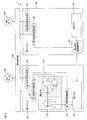
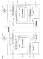
- FIG. 1 is a circuit diagram showing an overall configuration of a motor control device 1 according to the first embodiment.
- the motor control device 1 includes a first microcomputer 100, a second microcomputer 200, an integrated control unit 300, a first motor 400, and a second motor 500.
- the first microcomputer 100 includes a first CPU 120, a second CPU 110, a first internal communication function unit 130, a first failure determination notification unit 140, and a first PWM signal generation unit 150, and generates a PWM signal for motor control. Or failure diagnosis of the first CPU 120 or the second CPU 110 is performed.
- the first microcomputer 100 is a multi-core microcomputer having a second CPU 110 and a first CPU 120.
- the first internal communication function unit 130 is provided between the second CPU 110 and the first CPU 120, and detects a failure of the first CPU 120 by performing communication via a shared memory or the like.
- the first failure determination notification unit 140 receives a failure notification from the first internal communication function unit 130 or the like, and notifies the integrated control unit 300 of a result of the retry determined as a true failure.
- the first PWM signal generation unit 150 generates a PWM signal for motor control, and outputs the PWM signal to the integrated control unit 300.
- the first PWM signal generation unit 150 is operated by the second CPU 110.
- the second CPU 110 includes a first core 111 and a first self-diagnosis function unit 115.
- the first self-diagnosis function unit 115 includes a second core 112 and a failure diagnosis unit 113.
- the first core 111 has a calculation function. For example, it has a function of outputting general CPU instruction fetch, decoding, arithmetic processing, and arithmetic results to a memory or the like. Further, the first core 111 detects a failure of a bus, an IO controller, an internal memory, and the like that are core peripheral modules of the second CPU 110. Then, the first core 111 transmits the calculation processing result to the failure diagnosis unit 113.
- the second core 112 has a calculation function. For example, it has a function of outputting general CPU instruction fetch, decoding, arithmetic processing, and arithmetic results to a memory or the like. Then, the same calculation as that of the first core 111 is performed, and the calculation processing result is transmitted to the failure diagnosis unit 113.
- the failure diagnosis unit 113 compares the arithmetic processing result of the first core 111 with the arithmetic processing result of the second core 112 and determines that it is abnormal if they do not match. If it is not possible to recover from the abnormality, it is determined that the second CPU 110 has failed, and the first failure determination notification unit 140 is informed of the failure.
- the first self-diagnosis function unit 115 includes the second core described above, and a failure diagnosis unit 113 that compares the operation processing result of the first core 111 and the operation processing result of the second core 112 to diagnose a failure.
- the first internal communication function unit 130 is provided between the second CPU 110 and the first CPU 120, and the first core 111 communicates with the first CPU 120 via a shared memory or the like, and communicates via the shared memory or the like. Thus, the failure of the first CPU 120 is detected. When a failure is detected, the failure is transmitted to the first failure determination notification unit 140.
- the first failure determination notification unit 140 receives a failure notification from the first self-diagnosis function unit 115 and the first internal communication function unit 130, and is true when the result of the retry, i.e., the notification of a predetermined number of failures, is received. Is notified to the integrated control unit 300. Specifically, when the failure from the first self-diagnostic function unit 115 is received and it is determined that the failure is true, the second CPU 110 notifies the integrated control unit 300 that the failure has occurred. In addition, when the failure is received from the first internal communication function unit 130 and is determined to be a true failure, the integrated control unit 300 is notified of the failure of the first CPU 120.
- the second microcomputer 200 includes a third CPU 210, a second external communication function unit 260, a second failure determination notification unit 240, and a second PWM signal generation unit 250, and generates a PWM signal for motor control, 1 Diagnosis of failure of the microcomputer 100 is performed.
- the second external communication function unit 260 detects a failure of the first microcomputer 100 by communicating with the first CPU 120 of the first microcomputer 100 and the second microcomputer 200. Specifically, the first CPU 120 processes the example calculation from the third CPU 210 and confirms the coincidence of the result. If they do not match, it is determined that the first CPU 120 has failed, and the second failure determination notification unit 240 is notified of the failure.
- the second failure determination notification unit 240 receives a failure notification from the second external communication function unit 260, and notifies the integrated control unit 300 of a result of the retry determined as a true failure. Specifically, when the failure is received from the second external communication function unit 260 and it is determined that the failure is truly a failure, the integrated control unit 300 is notified that the first CPU 120 is a failure.
- the second PWM signal generation unit 250 generates a PWM signal for motor control, and outputs the PWM signal to the integrated control unit 300.
- the integrated control unit 300 performs failure determination based on notifications from the first failure determination notification unit 140 and the second failure determination notification unit 240, and if normal, the PWM signal transmitted from the first PWM signal generation unit 150 is output.
- the PWM signal is supplied to the first motor 400 and the PWM signal sent from the second PWM signal generator 250 is supplied to the second motor 500.
- the integrated control unit 300 performs the failure determination based on the notifications from the first failure determination notification unit 140 and the second failure determination notification unit 240. For example, when the second CPU 110 is determined to have failed, the first PWM signal generation unit Control is performed so that the PWM signal sent from 150 is not supplied to the first motor 400.
- the first motor 400 is a drive motor used for driving the vehicle
- the second motor 500 is a regenerative motor.
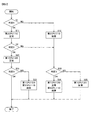
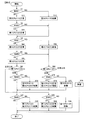
- FIG. 2 is a flowchart for explaining the failure determination operation of the integrated control unit 300.
- the first microcomputer 100 and the second microcomputer 200 always perform failure diagnosis, and the diagnosis result is obtained from the first failure determination notification unit 140 of the first microcomputer 100 and the second failure determination notification unit 240 of the second microcomputer 200.
- the notification is sent to the integrated control unit 300.
- FIG. 2 shows an operation executed by a control unit (not shown) of the integrated control unit 300.
- a logic circuit that operates in the same manner as the operation shown in this flowchart may be provided as hardware in the integrated control unit 300.
- the integrated control unit 300 starts a failure determination of the second CPU 110 and the first CPU 120 of the first microcomputer 100. Note that the failure indicates that an operation other than the assumption is continuously performed, and indicates a hardware failure and a software failure.
- Step S1 is to monitor the failure of the second CPU 110 of the first microcomputer 100, and makes a determination based on the result of the first self-diagnosis function unit 115 of the first microcomputer 100 (determination mode 1). If normal, the process proceeds to step S11, and the second CPU 110 determines normal. If there is a failure, the process proceeds to step S12, and the second CPU 110 determines that there is a failure. After the determination in step S11, the process proceeds to step S2, and after the determination in step S12, the process proceeds to step S32.
- Step S2 is for monitoring a failure between the first CPU 120 and the second CPU 110 of the first microcomputer 100, and determining based on the result of the first internal communication function unit 130 (determination mode 2). If normal, the process proceeds to step S21, and the first CPU 120 determines that it is normal. If there is a failure, the process proceeds to step S32. After the determination in step S21, the process proceeds to step S31.
- Step S31 monitors the failure of the first microcomputer 100 and the failure of the first CPU 120 of the first microcomputer, and makes a determination based on the result of the second external communication function unit 260 (determination mode 3). If it is normal, the first CPU 120 determines that it is normal, as already determined in step S21. In the case of failure, the process proceeds to step S33, and the second CPU 110 and the first CPU 120 determine that there is a failure. This determination is a diagnosis that takes into account when the first self-diagnostic function unit 115 has failed, and is inconsistent with the determinations in step S11 and step S21.
- step S32 monitors the failure of the first microcomputer 100 and the failure of the first CPU 120 of the first microcomputer, and makes a determination based on the result of the second external communication function unit 260 (determination) Mode 3). If normal, the process proceeds to step S34, and it is determined that the first CPU 120 is normal and the second CPU 110 is faulty. Since this determination is inconsistent with the determination in step S2, according to step S32, it is determined that the second CPU 110 is faulty, and further, it is determined that the first CPU 120 is normal. Therefore, in this case, the processing of the first CPU 120 can be continued.
- step S32 if there is a failure, the process proceeds to step S35, and the first CPU 120 determines that there is a failure.
- the integrated control unit 300 performs control to block the PWM signal transmitted from the first PWM signal generation unit 150 without supplying the PWM signal to the first motor 400.
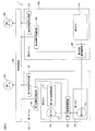
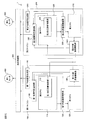
- FIG. 3 is a circuit diagram showing the overall configuration of the motor control device 1 according to the second embodiment.
- the configurations of the first internal communication function unit 130 and the first CPU 120 are different from those of the first embodiment.
- the motor control device 1 includes a first microcomputer 100, a second microcomputer 200, an integrated control unit 300, a first motor 400, and a second motor 500.
- the first microcomputer 100 includes a first CPU 120, a second CPU 110, a first internal communication function unit 130, a first failure determination notification unit 140, and a first PWM signal generation unit 150, and generates a PWM signal for motor control. Or failure diagnosis of the first CPU 120 or the second CPU 110 is performed.
- the first microcomputer 100 is a multi-core microcomputer having a second CPU 110 and a first CPU 120.
- the first internal communication function unit 130 is provided between the second CPU 110 and the first CPU 120, and detects a failure of the first CPU 120 by performing communication via a shared memory or the like.
- the first failure determination notification unit 140 receives a failure notification from the first internal communication function unit 130 or the like, and notifies the integrated control unit 300 of a result of the retry determined as a true failure.
- the first PWM signal generation unit 150 generates a PWM signal for motor control, and outputs the PWM signal to the integrated control unit 300.
- the first PWM signal generation unit 150 is operated by the second CPU 110.
- the second CPU 110 includes a first core 111 and a first self-diagnosis function unit 115. Since the second CPU 110 has the same configuration as that shown in the first embodiment, its details are omitted.
- the first self-diagnosis function unit 115 compares the calculation processing result of the first core 111 with the calculation processing result of the second core (not shown) in the first self-diagnosis function unit 115 to diagnose a failure of the second CPU 110, The failure is notified to the first failure determination notification unit 140.
- the first CPU 120 includes a third core 121, and the third core 121 has an arithmetic function. For example, it has a function of outputting general CPU instruction fetch, decoding, arithmetic processing, and arithmetic results to a memory or the like.
- the first internal communication function unit 130 is provided between the first core 111 of the second CPU 110 and the third core 121 of the first CPU 120, and the second CPU 110 communicates with the first CPU 120 via a shared memory or the like, and the shared memory
- the failure of the first CPU 120 is detected by performing communication via the communication. Further, the first CPU 120 communicates with the second CPU 110 via a shared memory or the like, and performs communication via the shared memory or the like, thereby detecting a failure of the second CPU 110. When a failure is detected, the failure is notified to the first failure determination notification unit 140.
- the first failure determination notification unit 140 receives a failure notification from the first self-diagnostic function unit 115 and the first internal communication function unit 130, and notifies the integrated control unit 300 of a result of the retry determined as a true failure. . Specifically, when the failure from the first self-diagnostic function unit 115 is received and it is determined that the failure is true, the second CPU 110 notifies the integrated control unit 300 that the failure has occurred. Further, when it is determined that the failure is true from the failure of the first internal communication function unit 130, it is determined that the first CPU 120 is defective, and further, the failure from the first internal communication function unit 130 is received, When it is determined that the failure is true, the integrated control unit 300 is notified that the second CPU 110 is in failure.
- the second microcomputer 200 includes a third CPU 210, a second external communication function unit 260, a second failure determination notification unit 240, and a second PWM signal generation unit 250, and generates a PWM signal for motor control, 1 Diagnosis of failure of the microcomputer 100 is performed.
- the second external communication function unit 260 detects a failure of the first microcomputer 100 by communicating with the third core 121 of the first CPU 120 of the first microcomputer 100 and the second microcomputer 200. Specifically, the example calculation from the third CPU 210 is processed by the third core 121 of the first CPU 120, and the coincidence of the result is confirmed. If they do not match, it is determined that the first CPU 120 has failed, and the second failure determination notification unit 240 is notified of the failure.
- the second failure determination notification unit 240 receives a failure notification from the second external communication function unit 260, and notifies the integrated control unit 300 of a result of the retry determined as a true failure. Specifically, when the failure is received from the second external communication function unit 260 and it is determined that the failure is truly a failure, the integrated control unit 300 is notified that the first CPU 120 is a failure.
- the second PWM signal generation unit 250 generates a PWM signal for motor control, and outputs the PWM signal to the integrated control unit 300.
- the integrated control unit 300 performs failure determination based on notifications from the first failure determination notification unit 140 and the second failure determination notification unit 240, and if normal, the PWM signal transmitted from the first PWM signal generation unit 150 is output.
- the PWM signal is supplied to the first motor 400 and the PWM signal sent from the second PWM signal generator 250 is supplied to the second motor 500.
- the integrated control unit 300 performs the failure determination based on the notifications from the first failure determination notification unit 140 and the second failure determination notification unit 240. For example, when the second CPU 110 is determined to have failed, the first PWM signal generation unit Control is performed so that the PWM signal sent from 150 is not supplied to the first motor 400.
- the first motor 400 is a drive motor used for driving the vehicle
- the second motor 500 is a regenerative motor.
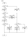
- FIG. 4 is a flowchart for explaining the failure determination operation of the integrated control unit 300.
- the first microcomputer 100 and the second microcomputer 200 always perform failure diagnosis, and the diagnosis result is obtained from the first failure determination notification unit 140 of the first microcomputer 100 and the second failure determination notification unit 240 of the second microcomputer 200.
- the notification is sent to the integrated control unit 300.
- FIG. 4 shows an operation performed by a control unit (not shown) of the integrated control unit 300.
- a logic circuit that operates in the same manner as the operation shown in this flowchart may be provided as hardware in the integrated control unit 300.
- the integrated control unit 300 starts a failure determination of the second CPU 110 and the first CPU 120 of the first microcomputer 100. Note that the failure indicates that an operation other than the assumption is continuously performed, and indicates a hardware failure and a software failure.
- Step S1 is to monitor the failure of the second CPU 110 of the first microcomputer 100, and makes a determination based on the result of the first self-diagnosis function unit 115 of the first microcomputer 100 (determination mode 1). If normal, the process proceeds to step S11, and the second CPU 110 determines normal. If there is a failure, the process proceeds to step S12, and the second CPU 110 determines that there is a failure. After the determination in step S11, the process proceeds to step S2-1. After the determination in step S12, the process proceeds to step S32.
- Step S2-1 is for monitoring the failure of the first CPU 120 to the second CPU 110 of the first microcomputer 100, and making a determination based on the result of the first internal communication function unit 130 (determination mode 21). If normal, the process proceeds to step S2-2. If there is a failure, the process proceeds to step S32.
- Step S2-2 monitors the failure of the first CPU 120 from the second CPU 110 of the first microcomputer 100, and makes a determination based on the result of the first internal communication function unit 130 (determination mode 22). If normal, the process proceeds to step S21, and the first CPU 120 determines that it is normal. If there is a failure, the process proceeds to step S2-3.
- Step S2-3 determines that the second CPU 110 of the first microcomputer 100 is in failure.
- the first self-diagnostic function unit 115 of the second CPU 110 indicates a failure.
- the process proceeds to step S32.
- Step S31 monitors the failure of the first microcomputer 100 and the failure of the first CPU 120 of the first microcomputer, and makes a determination based on the result of the second external communication function unit 260 (determination mode 3). If it is normal, the first CPU 120 determines that it is normal, as already determined in step S21. In the case of failure, the process proceeds to step S33, and the second CPU 110 and the first CPU 120 determine that there is a failure. This determination is a diagnosis that takes into account when the first self-diagnostic function unit 115 has failed, and is inconsistent with the determinations in step S11 and step S21.
- step S32 monitors the failure of the first microcomputer 100 and the failure of the first CPU 120 of the first microcomputer, and makes a determination based on the result of the second external communication function unit 260 (determination) Mode 3). If normal, the process proceeds to step S34, and it is determined that the first CPU 120 is normal and the second CPU 110 is faulty. Since this determination is inconsistent with the determination in step S2, according to step S32, it is determined that the second CPU 110 is faulty, and further, it is determined that the first CPU 120 is normal. Therefore, in this case, the processing of the first CPU 120 can be continued.
- step S32 if there is a failure, the process proceeds to step S35, and the first CPU 120 determines that there is a failure.
- the integrated control unit 300 performs control to block the PWM signal transmitted from the first PWM signal generation unit 150 without supplying the PWM signal to the first motor 400.
- the failure of the first CPU 120 and the second CPU 110 can be detected, but in the second embodiment, the failure of the first CPU 120, the second CPU 110, and the first self-diagnostic function unit 115 can be detected.
- FIG. 5 is a circuit diagram showing the overall configuration of the motor control device 1 according to the third embodiment.
- a first external communication function unit 160, a fourth CPU 220, and a second internal communication function unit 230 are added to the first embodiment.
- the motor control device 1 includes a first microcomputer 100, a second microcomputer 200, an integrated control unit 300, a first motor 400, and a second motor 500.
- the first microcomputer 100 includes a first CPU 120, a second CPU 110, a first internal communication function unit 130, a first failure determination notification unit 140, and a first PWM signal generation unit 150, and generates a PWM signal for motor control. Or failure diagnosis of the first CPU 120 or the second CPU 110 is performed.
- the first microcomputer 100 is a multi-core microcomputer having a second CPU 110 and a first CPU 120.
- the first internal communication function unit 130 is provided between the second CPU 110 and the first CPU 120, and detects a failure of the first CPU 120 by performing communication via a shared memory or the like.
- the first failure determination notification unit 140 receives a failure notification from the first self-diagnostic function unit 115, the first internal communication function unit 130, and a first external communication function unit 160 described later, and as a result of the retry, a true failure is detected. To the integrated control unit 300. Specifically, when the failure from the first self-diagnostic function unit 115 is received and it is determined that the failure is true, the second CPU 110 notifies the integrated control unit 300 that the failure has occurred. In addition, when the failure is received from the first internal communication function unit 130 and is determined to be a true failure, the integrated control unit 300 is notified of the failure of the first CPU 120.
- the first PWM signal generation unit 150 generates a PWM signal for motor control, and outputs the PWM signal to the integrated control unit 300.
- the first PWM signal generation unit 150 is operated by the second CPU 110.
- the second CPU 110 includes a first self-diagnosis function unit 115. Since the second CPU 110 has the same configuration as that shown in the first embodiment, its details are omitted.
- the first self-diagnosis function unit 115 compares the arithmetic processing result of the first core 111 (not shown) and the arithmetic processing result of the second core 112 to diagnose the failure of the second CPU 110 and notifies the first failure determination notification unit 140 of the failure. Tell.
- the first internal communication function unit 130 is provided between the second CPU 110 and the first CPU 120.
- the second CPU 110 communicates with the first CPU 120 via a shared memory or the like, and performs communication via the shared memory or the like.
- a failure of the first CPU 120 is detected.
- the failure is notified to the first failure determination notification unit 140.
- the first external communication function unit 160 detects a failure of the second microcomputer 200 by communicating with the third CPU 210 of the second microcomputer 200 and the first microcomputer 100. Specifically, the example calculation from the first CPU 120 is processed by the third CPU 210 via the second external communication function unit 260, and the result is confirmed to confirm the match. If they do not match, it is determined that the third CPU 210 has failed, and the first failure determination notification unit 140 is notified of the failure.
- the second microcomputer 200 includes a third CPU 210, a fourth CPU 220, a second internal communication function unit 230, a second external communication function unit 260, a second failure determination notification unit 240, and a second PWM signal generation unit 250.
- the PWM signal for motor control is generated, the self-diagnosis of the second microcomputer 200, the failure diagnosis of the first microcomputer 100, and the like are performed.
- the second microcomputer 200 is a multi-core microcomputer having a fourth CPU 220 and a third CPU 210.
- the fourth CPU 220 includes a second self-diagnosis function unit 225.
- the second self-diagnosis function unit 225 has the same configuration as the first self-diagnosis function unit 115 of the second CPU 110, diagnoses a failure of the fourth CPU 220, and notifies the second failure determination notification unit 240 of the failure.
- the second internal communication function unit 230 is provided between the fourth CPU 220 and the third CPU 210.
- the fourth CPU 220 communicates with the third CPU 210 via a shared memory or the like, and performs communication via the shared memory or the like.
- a failure of the third CPU 210 is detected.
- the failure is notified to the second failure determination notification unit 240.
- the second external communication function unit 260 detects a failure of the first microcomputer 100 by communicating with the first CPU 120 of the first microcomputer 100 and the second microcomputer 200. Specifically, the example operation from the third CPU 210 is processed by the first CPU 120 via the first external communication function unit 160, and the match is confirmed by receiving the result. If they do not match, it is determined that the first CPU 120 has failed, and the second failure determination notification unit 240 is notified of the failure.
- the second failure determination notification unit 240 receives a failure notification from the second self-diagnostic function unit 225, the second internal communication function unit 230, and the second external communication function unit 260, and as a result of the retry, determines that it is truly a failure. Is notified to the integrated control unit 300. Specifically, if the failure is received from the second self-diagnostic function unit 225 and is determined to be a true failure, the fourth CPU 220 notifies the integrated control unit 300 that the failure has occurred. In addition, when it is determined that a failure has actually occurred due to a failure from the second internal communication function unit 230, the third CPU 210 notifies the integrated control unit 300 that the failure has occurred. In addition, when the failure from the second external communication function unit 260 is received and it is determined that the failure is true, the first CPU 120 notifies the integrated control unit 300 that the failure has occurred.
- the second PWM signal generation unit 250 generates a PWM signal for motor control, and outputs the PWM signal to the integrated control unit 300.
- the integrated control unit 300 performs failure determination based on notifications from the first failure determination notification unit 140 and the second failure determination notification unit 240, and if normal, the PWM signal transmitted from the first PWM signal generation unit 150 is output.
- the PWM signal is supplied to the first motor 400 and the PWM signal sent from the second PWM signal generator 250 is supplied to the second motor 500.
- the integrated control unit 300 performs the failure determination based on the notifications from the first failure determination notification unit 140 and the second failure determination notification unit 240. For example, when the second CPU 110 is determined to have failed, the first PWM signal generation unit Control is performed so that the PWM signal sent from 150 is not supplied to the first motor 400.
- the first motor 400 is a drive motor used for driving the vehicle
- the second motor 500 is a regenerative motor.
- FIG. 6 is a flowchart for explaining the failure determination operation of the integrated control unit 300.
- the first microcomputer 100 and the second microcomputer 200 always perform failure diagnosis, and the diagnosis result is obtained from the first failure determination notification unit 140 of the first microcomputer 100 and the second failure determination notification unit 240 of the second microcomputer 200.
- the notification is sent to the integrated control unit 300.
- the flowchart of FIG. 6 described below shows an operation performed by a control unit (not shown) of the integrated control unit 300.
- a logic circuit that operates in the same manner as the operation shown in this flowchart may be provided as hardware in the integrated control unit 300.
- the integrated control unit 300 starts the failure determination of the first microcomputer 100 and the second microcomputer 200. Note that the failure indicates that an operation other than the assumption is continuously performed, and indicates a hardware failure and a software failure.
- Step S1 is to monitor the failure of the second CPU 110 of the first microcomputer 100, and makes a determination based on the result of the first self-diagnosis function unit 115 of the first microcomputer 100 (determination mode 1). If normal, the process proceeds to step S11, and the second CPU 110 determines normal. If there is a failure, the process proceeds to step S12, and the second CPU 110 determines that there is a failure. After the determination in step S11, the process proceeds to step S2, and after the determination in step S12, the process proceeds to step S4.
- Step S2 is for monitoring a failure between the first CPU 120 and the second CPU 110 of the first microcomputer 100, and determining based on the result of the first internal communication function unit 130 (determination mode 2). If normal, the process proceeds to step S21, and the first CPU 120 determines that it is normal. If there is a failure, the process proceeds to step S4. After the determination in step S21, the process proceeds to step S4.
- Step S4 monitors the failure of the fourth CPU 220 of the second microcomputer 200, and makes a determination based on the result of the second self-diagnostic function unit 225 of the second microcomputer 200 (determination mode 1). If normal, the process proceeds to step S41, and the fourth CPU 220 determines normal. In the case of failure, the process proceeds to step S42, and the fourth CPU 220 determines that there is a failure. After the determination in step S41, the process proceeds to step S5, and after the determination in step S42, the process proceeds to step S62.
- Step S5 is for monitoring a failure between the third CPU 210 and the fourth CPU 220 of the second microcomputer 200 and making a determination based on the result of the second internal communication function unit 230 (determination mode 2). If normal, the process proceeds to step S51, and the third CPU 210 determines normal. If there is a failure, the process proceeds to step S62. After the determination in step S51, the process proceeds to step S61.
- Step S61 determines whether or not the first CPU 120 is normal. If normal, the process proceeds to step S71, and if not normal, the process proceeds to step S32. This step determination is performed by determining the determination result of step S1.
- Step S32 monitors the failure of the first microcomputer 100 and the failure of the first CPU 120 of the first microcomputer, and makes a determination based on the result of the second external communication function unit 260 (determination mode 3). If normal, the process proceeds to step S34, and it is determined that the first CPU 120 is normal and the second CPU 110 is faulty. Since this determination is inconsistent with the determinations in steps S2 and S61, it is determined that the second CPU 110 is faulty and the first CPU 120 is determined to be normal according to step S32. Therefore, in this case, the processing of the first CPU 120 can be continued.
- step S32 if there is a failure, the process proceeds to step S35, and the first CPU 120 determines that there is a failure.
- Step S71 monitors the failure of the second microcomputer 200 and the failure of the third CPU 210 of the second microcomputer 200, and makes a determination based on the result of the first external communication function unit 160 (determination mode 3). If normal, the process proceeds to step S31.
- Step S31 monitors the failure of the first microcomputer 100 and the failure of the first CPU 120 of the first microcomputer, and makes a determination based on the result of the second external communication function unit 260 (determination mode 1). If it is normal, the first CPU 120 determines that it is normal, as already determined in step S21. In the case of failure, the process proceeds to step S33, and the second CPU 110 and the first CPU 120 determine that there is a failure. This determination is a diagnosis that takes into account when the first self-diagnostic function unit 115 has failed, and is inconsistent with the determinations in step S11 and step S21.
- Step S73 is a diagnosis that takes into account the failure of the second self-diagnosis function unit 225. Since there is a contradiction with the determinations of steps S41 and S51, it is determined that the third CPU 210 and the fourth CPU 220 are defective. After the determination in step S73, the process proceeds to step S31.
- step S62 as in step S61, it is determined whether or not the first CPU 120 is normal. If normal, the process proceeds to step S72, and if not normal, the process proceeds to step S76.
- Step S72 monitors the failure of the second microcomputer 200 and the failure of the third CPU 210 of the second microcomputer 200, and makes a determination based on the result of the first external communication function unit 160 (determination mode 3). If normal, the process proceeds to step S74.
- Step S74 determines that the third CPU 210 is normal and the fourth CPU 220 is faulty. Since this determination is inconsistent with the determination in step S5, it is determined in accordance with step S72 that the fourth CPU 220 is faulty and further that the third CPU 210 is normal. Therefore, in this case, the processing of the third CPU 210 can be continued.
- step S72 if there is a failure, the process proceeds to step S75, and the third CPU 210 determines that there is a failure.
- step S76 it is determined that the first microcomputer 100 and the second microcomputer 200 have failed at the same time, but it is not assumed that the microcomputers which are different modules will simultaneously fail for the same cause, and the determination is ignored.
- the integrated control unit 300 performs control to block the PWM signal transmitted from the first PWM signal generation unit 150 without supplying the PWM signal to the first motor 400. Further, for example, when it is determined that the third CPU 210 or the fourth CPU 220 is out of order, control is performed to block the PWM signal sent from the second PWM signal generation unit 250 without supplying it to the second motor 500.
- FIG. 7 is a circuit diagram showing the overall configuration of the motor control device 1 according to the fourth embodiment.
- the motor control device 1 includes a first microcomputer 100, a second microcomputer 200, an integrated control unit 300, a first motor 400, and a second motor 500.
- the first microcomputer 100 includes a first CPU 120, a second CPU 110, a first internal communication function unit 130, a first failure determination notification unit 140, and a first PWM signal generation unit 150, and generates a PWM signal for motor control. Or failure diagnosis of the first CPU 120 or the second CPU 110 is performed.
- the first microcomputer 100 is a multi-core microcomputer having a second CPU 110 and a first CPU 120.
- the first internal communication function unit 130 is provided between the second CPU 110 and the first CPU 120, and detects a failure of the first CPU 120 by performing communication via a shared memory or the like.
- the first failure determination notification unit 140 receives a failure notification from the first internal communication function unit 130 or the like, and notifies the integrated control unit 300 of a result of the retry determined as a true failure. Specifically, when the failure from the first self-diagnostic function unit 115 is received and it is determined that the failure is true, the second CPU 110 notifies the integrated control unit 300 that the failure has occurred. In addition, when the failure is received from the first internal communication function unit 130 and is determined to be a true failure, the integrated control unit 300 is notified of the failure of the first CPU 120. In addition, when the failure is received from the first external communication function unit 160 and is determined to be truly a failure, the fourth CPU 220 notifies the integrated control unit 300 that the failure has occurred.
- the first PWM signal generation unit 150 generates a PWM signal for motor control, and outputs the PWM signal to the integrated control unit 300.
- the first PWM signal generation unit 150 is operated by the second CPU 110.
- the second CPU 110 includes a first self-diagnosis function unit 115. Since the second CPU 110 has the same configuration as that shown in the first embodiment, its details are omitted.
- the first self-diagnosis function unit 115 compares the arithmetic processing result of the first core 111 (not shown) and the arithmetic processing result of the second core 112 to diagnose the failure of the second CPU 110 and notifies the first failure determination notification unit 140 of the failure. Tell.
- the first internal communication function unit 130 is provided between the second CPU 110 and the first CPU 120.
- the second CPU 110 communicates with the first CPU 120 via a shared memory or the like, and performs communication via the shared memory or the like.
- a failure of the first CPU 120 is detected.
- the failure is notified to the first failure determination notification unit 140.
- the first external communication function unit 160 detects a failure of the second microcomputer 200 by communicating with the fourth CPU 220 of the second microcomputer 200 and the first microcomputer 100. Specifically, the fourth CPU 220 processes the example calculation from the first CPU 120 and confirms that the results match. If they do not match, it is determined that the fourth CPU 220 has failed, and the first failure determination notification unit 140 is notified of the failure.
- the second microcomputer 200 includes a third CPU 210, a fourth CPU 220, a second internal communication function unit 230, a second external communication function unit 260, a second failure determination notification unit 240, and a second PWM signal generation unit 250.
- the PWM signal for motor control is generated, the self-diagnosis of the second microcomputer 200, the failure diagnosis of the first microcomputer 100, and the like are performed.
- the second microcomputer 200 is a multi-core microcomputer having a fourth CPU 220 and a third CPU 210.
- the fourth CPU 220 includes a second self-diagnosis function unit 225.
- the second self-diagnosis function unit 225 has the same configuration as the first self-diagnosis function unit 115 of the second CPU 110, diagnoses a failure of the fourth CPU 220, and notifies the second failure determination notification unit 240 of the failure.
- the second internal communication function unit 230 is provided between the fourth CPU 220 and the third CPU 210.
- the fourth CPU 220 communicates with the third CPU 210 via a shared memory or the like, and performs communication via the shared memory or the like.
- a failure of the third CPU 210 is detected.
- the failure is notified to the second failure determination notification unit 240.
- the second external communication function unit 260 detects a failure of the first microcomputer 100 by communicating with the second CPU 110 of the first microcomputer 100 and the second microcomputer 200. Specifically, the second CPU 110 processes the example calculation from the third CPU 210 and confirms the coincidence of the result. If they do not match, it is determined that the second CPU 110 has failed, and the second failure determination notification unit 240 is notified of the failure.
- the second failure determination notification unit 240 receives a failure notification from the second self-diagnostic function unit 225, the second internal communication function unit 230, and the second external communication function unit 260, and as a result of the retry, determines that it is truly a failure. Is notified to the integrated control unit 300. Specifically, if the failure is received from the second self-diagnostic function unit 225 and is determined to be a true failure, the fourth CPU 220 notifies the integrated control unit 300 that the failure has occurred. In addition, when it is determined that a failure has actually occurred due to a failure from the second internal communication function unit 230, the third CPU 210 notifies the integrated control unit 300 that the failure has occurred. In addition, when it is determined that the failure is actually caused by the failure from the second external communication function unit 260, the integrated control unit 300 is notified that the second CPU 110 is in failure.
- the second PWM signal generation unit 250 generates a PWM signal for motor control, and outputs the PWM signal to the integrated control unit 300.
- the integrated control unit 300 performs failure determination based on notifications from the first failure determination notification unit 140 and the second failure determination notification unit 240, and if normal, the PWM signal transmitted from the first PWM signal generation unit 150 is output.
- the PWM signal is supplied to the first motor 400 and the PWM signal sent from the second PWM signal generator 250 is supplied to the second motor 500.
- the integrated control unit 300 performs the failure determination based on the notifications from the first failure determination notification unit 140 and the second failure determination notification unit 240. For example, when the second CPU 110 is determined to have failed, the first PWM signal generation unit Control is performed so that the PWM signal sent from 150 is not supplied to the first motor 400.
- the first motor 400 is a drive motor used for driving the vehicle
- the second motor 500 is a regenerative motor.
- FIG. 8 is a flowchart illustrating the failure determination operation of the integrated control unit 300.
- the first microcomputer 100 and the second microcomputer 200 always perform failure diagnosis, and the diagnosis result is obtained from the first failure determination notification unit 140 of the first microcomputer 100 and the second failure determination notification unit 240 of the second microcomputer 200.
- the notification is sent to the integrated control unit 300.
- FIG. 8 shows an operation executed by a control unit (not shown) of the integrated control unit 300.
- a logic circuit that operates in the same manner as the operation shown in this flowchart may be provided as hardware in the integrated control unit 300.
- the integrated control unit 300 starts the failure determination of the first microcomputer 100 and the second microcomputer 200. Note that the failure indicates that an operation other than the assumption is continuously performed, and indicates a hardware failure and a software failure.
- Step S1 is to monitor the failure of the second CPU 110 of the first microcomputer 100, and makes a determination based on the result of the first self-diagnosis function unit 115 of the first microcomputer 100 (determination mode 1). If normal, the process proceeds to step S11, and the second CPU 110 determines normal. If there is a failure, the process proceeds to step S12, and the second CPU 110 determines that there is a failure. After the determination in step S11, the process proceeds to step S2, and after the determination in step S12, the process proceeds to step S4.
- Step S2 is for monitoring a failure between the first CPU 120 and the second CPU 110 of the first microcomputer 100, and determining based on the result of the first internal communication function unit 130 (determination mode 2). If normal, the process proceeds to step S21, and the first CPU 120 determines that it is normal. If there is a failure, the process proceeds to step S4. After the determination in step S21, the process proceeds to step S4.
- Step S4 monitors the failure of the fourth CPU 220 of the second microcomputer 200, and makes a determination based on the result of the second self-diagnostic function unit 225 of the second microcomputer 200 (determination mode 1). If normal, the process proceeds to step S41, and the fourth CPU 220 determines normal. In the case of failure, the process proceeds to step S42, and the fourth CPU 220 determines that there is a failure. After the determination in step S41, the process proceeds to step S5, and after the determination in step S42, the process proceeds to step S62 '.
- Step S5 is for monitoring a failure between the third CPU 210 and the fourth CPU 220 of the second microcomputer 200 and making a determination based on the result of the second internal communication function unit 230 (determination mode 2). If normal, the process proceeds to step S51, and the third CPU 210 determines normal. If there is a failure, the process proceeds to step S62 '. After the determination in step S51, the process proceeds to step S61 '.
- Step S61 determines whether or not the second CPU 110 is normal. If normal, the process proceeds to step S71. If not normal, the process proceeds to step S32.
- Step S32 monitors the failure of the first microcomputer 100 and the failure of the second CPU 110 of the first microcomputer, and makes a determination based on the result of the second external communication function unit 260 (determination mode 3). If normal, the process proceeds to step S34 ', and it is determined that the first CPU 120 is out of order and the second CPU 110 is normal. Since this determination is inconsistent with the determinations in steps S1 and S61 ', in accordance with step S32, it is determined that the second CPU 110 is normal, and it is further determined that the first CPU 120 is faulty. Therefore, in this case, the processing of the second CPU 110 can be continued.
- step S32 if there is a failure, the process proceeds to step S35 ', and the second CPU 110 determines that there is a failure.
- step S61 ' if the second CPU 110 is normal, the process proceeds to step S71.
- Step S71 monitors the failure of the second microcomputer 200 and the fourth CPU 220 of the second microcomputer 200, and makes a determination based on the result of the first external communication function unit 160 (determination mode 3). If normal, the process proceeds to step S31.
- Step S31 monitors the failure of the first microcomputer 100 and the failure of the second CPU 110 of the first microcomputer, and makes a determination based on the result of the second external communication function unit 260. If it is normal, the first CPU 120 determines that it is normal, as already determined in steps S21 and S61 '. In the case of failure, the process proceeds to step S33, and the second CPU 110 and the first CPU 120 determine that there is a failure. This determination is a diagnosis that takes into account when the first self-diagnostic function unit 115 has failed, and is inconsistent with the determinations in step S11 and step S21.
- Step S73 is a diagnosis that takes into account the failure of the second self-diagnosis function unit 225. Since there is a contradiction with the determinations of steps S41 and S51, it is determined that the third CPU 210 and the fourth CPU 220 are defective. After the determination in step S73, the process proceeds to step S31.
- step S62 ' as in step S61', it is determined whether or not the second CPU 110 is normal. If normal, the process proceeds to step S72, and if not normal, the process proceeds to step S76.
- Step S72 monitors failure of the second microcomputer 200 and the fourth CPU 220 of the second microcomputer 200, and makes a determination based on the result of the first external communication function unit 160 (determination mode 3). If normal, the process proceeds to step S74 '. If not normal, the process proceeds to step S75.
- step S74 ' it is determined that the third CPU 210 is faulty and the fourth CPU 220 is normal. Since this determination is inconsistent with the determination in step S4, it is determined in step S72 that the fourth CPU 220 is normal and the third CPU 210 is in failure. Therefore, in this case, the process of the fourth CPU 220 can be continued.
- step S72 if there is a failure, the process proceeds to step S75, and the third CPU 210 determines that there is a failure.
- step S76 it is determined that the first microcomputer 100 and the second microcomputer 200 have failed at the same time, but it is not assumed that the microcomputers which are different modules will simultaneously fail for the same cause, and the determination is ignored.
- the integrated control unit 300 performs control to block the PWM signal transmitted from the first PWM signal generation unit 150 without supplying the PWM signal to the first motor 400. Further, for example, when it is determined that the third CPU 210 or the fourth CPU 220 is out of order, control is performed to block the PWM signal sent from the second PWM signal generation unit 250 without supplying it to the second motor 500.
- the third CPU 210 of the second microcomputer 200 if the third CPU 210 of the second microcomputer 200 is faulty, it is erroneously determined that the first CPU 120 and the second CPU 110 are faulty. However, the fourth embodiment Then, since the failure of the third CPU 210 of the second microcomputer 200 is also determined, no erroneous determination is made.
- the first self-diagnosis function unit 115, the first internal communication function unit 130, the first failure determination notification unit 140, and the first PWM signal generation unit 150 are shown as circuit configuration diagrams in the first microcomputer 100. A similar function may be realized by software processing in the microcomputer 100.
- the second self-diagnosis function unit 225, the second internal communication function unit 230, the second failure determination notification unit 240, and the second PWM signal generation unit 250 are shown as circuit configuration diagrams in the second microcomputer 200. The same function may be realized by software processing in the 200.
- the motor control device includes an integrated control unit 300 that receives information about a failure from the first microcomputer 100 and the second microcomputer 200 and controls the motors 400 and 500.
- the first microcomputer 100 includes a first CPU 120, a second CPU 110 having a first self-diagnosis function unit 115, and a first internal communication function unit 130 that detects a failure of the first CPU 120 by communicating from the second CPU 110 to the first CPU 120.
- the second microcomputer 200 includes a third CPU 210 and a second external communication function unit 260 that communicates from the third CPU 210 to the first microcomputer 100 to detect a failure of the first microcomputer 100.
- the integrated control unit 300 detects the failure detection result of the first internal communication function unit 130 and the second external communication function unit 260 even when the second CPU 110 is determined to have a failure by the first self-diagnosis function unit 115. Based on the above, the failure of the first CPU 120 is monitored, and the processing of the first CPU 120 is continued based on the monitoring result. Therefore, even if the second CPU is diagnosed as having a failure, the control of the motor mounted on the vehicle can be safely continued because the control of the first CPU can be continued.
- the present invention is not limited to the above-described embodiment, and other forms conceivable within the scope of the technical idea of the present invention are also included in the scope of the present invention as long as the characteristics of the present invention are not impaired. It is. Moreover, it is good also as a structure which combined the above-mentioned embodiment and a some modification.
- Second external communication function unit 100 1st microcomputer 200 2nd microcomputer 300 Integrated control part 400 1st motor 500 2nd motor 120 1st CPU 110 Second CPU 115 First self-diagnosis function unit 130 First internal communication function unit 140 First failure determination notification unit 150 First PWM signal generation unit 160 First external communication function unit 210 Third CPU 220 4th CPU 225 Second self-diagnosis function unit 230 Second internal communication function unit 240 Second failure determination notification unit 250 Second PWM signal generation unit 260 Second external communication function unit
Landscapes
- Engineering & Computer Science (AREA)
- Theoretical Computer Science (AREA)
- Power Engineering (AREA)
- Physics & Mathematics (AREA)
- General Physics & Mathematics (AREA)
- General Engineering & Computer Science (AREA)
- Transportation (AREA)
- Mechanical Engineering (AREA)
- Quality & Reliability (AREA)
- Life Sciences & Earth Sciences (AREA)
- Sustainable Development (AREA)
- Sustainable Energy (AREA)
- Automation & Control Theory (AREA)
- Computer Hardware Design (AREA)
- Health & Medical Sciences (AREA)
- Biomedical Technology (AREA)
- Control Of Electric Motors In General (AREA)
- Power Steering Mechanism (AREA)
- Debugging And Monitoring (AREA)
Abstract
Description
図1は、第1の実施の形態に係わるモータ制御装置1の全体構成を示す回路図である。
モータ制御装置1は、第1マイコン100と、第2マイコン200と、統合制御部300と、第1モータ400と、第2モータ500とを備えている。
第1マイコン100及び第2マイコン200は常時故障診断を行っており、その診断結果は、第1マイコン100の第1故障判定通知部140及び第2マイコン200の第2故障判定通知部240より、統合制御部300へ通知されている。
図3は、第2の実施の形態に係わるモータ制御装置1の全体構成を示す回路図である。第1内部通信機能部130と第1CPU120の構成が第1の実施の形態と相違する。
モータ制御装置1は、第1マイコン100と、第2マイコン200と、統合制御部300と、第1モータ400と、第2モータ500とを備えている。
第1マイコン100及び第2マイコン200は常時故障診断を行っており、その診断結果は、第1マイコン100の第1故障判定通知部140及び第2マイコン200の第2故障判定通知部240より、統合制御部300へ通知されている。
図5は、第3の実施の形態に係わるモータ制御装置1の全体構成を示す回路図である。第1の実施の形態に、第1外部通信機能部160と第4CPU220と第2内部通信機能部230とを付加した構成である。
モータ制御装置1は、第1マイコン100と、第2マイコン200と、統合制御部300と、第1モータ400と、第2モータ500とを備えている。
正常の場合は、ステップS31に進む。
図7は、第4の実施の形態に係わるモータ制御装置1の全体構成を示す回路図である。第3の実施の形態における、第1外部通信機能部160と第2外部通信機能部260の接続関係が異なる構成である。
モータ制御装置1は、第1マイコン100と、第2マイコン200と、統合制御部300と、第1モータ400と、第2モータ500とを備えている。
第1マイコン100及び第2マイコン200は常時故障診断を行っており、その診断結果は、第1マイコン100の第1故障判定通知部140及び第2マイコン200の第2故障判定通知部240より、統合制御部300へ通知されている。
本発明は、以上説明した第1~第4の実施の形態を次のように変形して実施することができる。
(1)モータ制御装置は、第1マイコン100及び第2マイコン200より故障に関する情報を受け取り、モータ400、500を制御する統合制御部300を備える。第1マイコン100は、第1CPU120と、第1自己診断機能部115を有する第2CPU110と、第2CPU110から第1CPU120へ通信をして第1CPU120の故障を検出する第1内部通信機能部130と有する。第2マイコン200は、第3CPU210と、第3CPU210から第1マイコン100へ通信して第1マイコン100の故障を検出する第2外部通信機能部260とを有する。統合制御部300は、第1マイコン100において、第2CPU110が第1自己診断機能部115により故障と判定された場合でも、第1内部通信機能部130と第2外部通信機能部260の故障検出結果に基づき、第1CPU120の故障を監視し、当該監視結果に基づき第1CPU120の処理を継続する。したがって、第2CPUが故障と診断されても、第1CPUの制御を継続できることにより、車両に搭載されるモータの制御が安全に継続可能である。
200 第2マイコン
300 統合制御部
400 第1モータ
500 第2モータ
120 第1CPU
110 第2CPU
115 第1自己診断機能部
130 第1内部通信機能部
140 第1故障判定通知部
150 第1PWM信号生成部
160 第1外部通信機能部
210 第3CPU
220 第4CPU
225 第2自己診断機能部
230 第2内部通信機能部
240 第2故障判定通知部
250 第2PWM信号生成部
260 第2外部通信機能部
Claims (6)
- 第1マイコン及び第2マイコンより故障に関する情報を受け取り、モータを制御する統合制御部を備え、
前記第1マイコンは、第1CPUと、第1自己診断機能部を有する第2CPUと、前記第2CPUから前記第1CPUへ通信をして前記第1CPUの故障を検出する第1内部通信機能部と有し、
前記第2マイコンは、第3CPUと、前記第3CPUから前記第1マイコンへ通信して前記第1マイコンの故障を検出する第2外部通信機能部とを有し、
前記統合制御部は、
前記第1マイコンにおいて、前記第2CPUが前記第1自己診断機能部により故障と判定された場合でも、前記第1内部通信機能部と前記第2外部通信機能部の故障検出結果に基づき、前記第1CPUの故障を監視し、当該監視結果に基づき前記第1CPUの処理を継続するモータ制御装置。 - 請求項1に記載のモータ制御装置において、
前記第1マイコンは、前記第2CPUと、前記第1CPUとを有するマルチコアマイコンであり、
前記第2CPUは、演算処理を実行する第1コアと演算処理を実行する第2コアを有し、
前記第1自己診断機能部は、前記第1コアの演算処理結果と前記第2コアの演算処理結果を比較して第2CPUの故障を検出し、
前記第1内部通信機能部は、前記第1コアと前記第1CPUと通信を行い、前記第1CPUの故障を検出するモータ制御装置。 - 請求項1または2のいずれか一項に記載のモータ制御装置において、
前記第1CPU及び前記第2CPUは、車両用のモータである第1モータの制御にかかわる処理を行い、
前記統合制御部は、
前記第1マイコンにおいて、前記第2CPUが前記第1自己診断機能部により故障と判定された場合でも、前記第1内部通信機能部と前記第2外部通信機能部の故障検出結果に基づき、前記第1CPUの故障を監視し、当該監視結果に基づき前記第1CPUの処理に基づき前記第1モータの制御を継続するモータ制御装置。 - 請求項2に記載のモータ制御装置において、
前記第1CPUは、演算処理を実行する第3コアを有し、
前記第1内部通信機能部は、前記第1コアから前記第3コアへの通信を行い、前記第1CPUの故障を検出し、且つ、前記第3コアから前記第1コアへの通信を行い、前記第2CPUの故障を検出するモータ制御装置。 - 請求項1~4に記載のモータ制御装置において、
前記第2マイコンは、前記第3CPUと、第4CPUとを有するマルチコアマイコンであり、
前記第2マイコンは、第3CPUと、第2自己診断機能部を有する第4CPUと、前記第4CPUから前記第3CPUへ通信して前記第3CPUの故障を検出する第2内部通信機能部と有し、
前記第1マイコンは、前記第1CPUから前記第2マイコンへ通信して前記第2マイコンの前記第3CPUの故障を検出する第1外部通信機能部とを有し、
前記統合制御部は、
前記第2マイコンにおいて、前記第4CPUが前記第2自己診断機能部により故障と判定された場合でも、前記第2内部通信機能部と前記第1外部通信機能部の故障検出結果に基づき、前記第3CPUの故障を監視し、当該監視結果に基づき前記第3CPUの処理を継続するモータ制御装置。 - 請求項1~4に記載のモータ制御装置において、
前記第2マイコンは、前記第3CPUと、第4CPUとを有するマルチコアマイコンであり、
前記第2マイコンは、第3CPUと、第2自己診断機能部を有する第4CPUと、前記第3CPUと前記第4CPUとの間で通信をして故障を検出する第2内部通信機能部と有し、
前記第2外部通信機能部は、前記第1CPUと前記第4CPUとの間で通信をして前記第4CPUの故障を検出し、
前記第1マイコンは、前記第1CPUから前記第2マイコンへ通信して前記第2マイコンの前記第4CPUの故障を検出する第1外部通信機能部とを有し、
前記統合制御部は、
前記第2マイコンにおいて、前記第4CPUが前記第2自己診断機能部により故障と判定された場合でも、前記第2内部通信機能部と前記第1外部通信機能部の故障検出結果に基づき、前記第4CPUの故障を監視し、当該監視結果に基づき前記第4CPUの処理を継続するモータ制御装置。
Priority Applications (4)
| Application Number | Priority Date | Filing Date | Title |
|---|---|---|---|
| CN201580031889.2A CN106462485B (zh) | 2014-06-20 | 2015-05-11 | 马达控制装置 |
| US15/320,003 US10254733B2 (en) | 2014-06-20 | 2015-05-11 | Motor control device |
| JP2016529163A JP6166473B2 (ja) | 2014-06-20 | 2015-05-11 | モータ制御装置 |
| DE112015002210.4T DE112015002210T5 (de) | 2014-06-20 | 2015-05-11 | Motorsteuervorrichtung |
Applications Claiming Priority (2)
| Application Number | Priority Date | Filing Date | Title |
|---|---|---|---|
| JP2014-126920 | 2014-06-20 | ||
| JP2014126920 | 2014-06-20 |
Publications (1)
| Publication Number | Publication Date |
|---|---|
| WO2015194282A1 true WO2015194282A1 (ja) | 2015-12-23 |
Family
ID=54935276
Family Applications (1)
| Application Number | Title | Priority Date | Filing Date |
|---|---|---|---|
| PCT/JP2015/063405 Ceased WO2015194282A1 (ja) | 2014-06-20 | 2015-05-11 | モータ制御装置 |
Country Status (5)
| Country | Link |
|---|---|
| US (1) | US10254733B2 (ja) |
| JP (1) | JP6166473B2 (ja) |
| CN (1) | CN106462485B (ja) |
| DE (1) | DE112015002210T5 (ja) |
| WO (1) | WO2015194282A1 (ja) |
Cited By (1)
| Publication number | Priority date | Publication date | Assignee | Title |
|---|---|---|---|---|
| JP2026520328A (ja) * | 2023-05-10 | 2026-06-23 | メルセデス・ベンツ グループ アクチェンゲゼルシャフト | 車両コンピューティングシステムのための複数システムオンチップ配置 |
Families Citing this family (10)
| Publication number | Priority date | Publication date | Assignee | Title |
|---|---|---|---|---|
| GB2546789A (en) * | 2016-01-29 | 2017-08-02 | Bombardier Primove Gmbh | Arrangement with battery system for providing electric energy to a vehicle |
| WO2018078870A1 (ja) * | 2016-10-31 | 2018-05-03 | 新電元工業株式会社 | 制御装置、および、制御装置の制御方法 |
| CN108089494A (zh) * | 2017-12-08 | 2018-05-29 | 中山市天隆燃具电器有限公司 | 一种可采集多种新能源汽车运行数据的系统 |
| JP2019142095A (ja) * | 2018-02-20 | 2019-08-29 | 京セラドキュメントソリューションズ株式会社 | 画像形成装置 |
| CN109358591B (zh) | 2018-08-30 | 2020-03-13 | 百度在线网络技术(北京)有限公司 | 车辆故障处理方法、装置、设备及存储介质 |
| IT201900018362A1 (it) * | 2019-10-10 | 2021-04-10 | Texa Spa | Metodo e sistema di controllo di almeno due motori elettrici di trazione di un veicolo |
| CN113067528B (zh) * | 2019-12-31 | 2023-01-06 | 比亚迪股份有限公司 | 电机控制系统和具有其的车辆 |
| GB202000939D0 (en) * | 2020-01-22 | 2020-03-04 | Mclaren Automotive Ltd | Motor control unit |
| DE102020210990A1 (de) * | 2020-09-01 | 2022-03-03 | Robert Bosch Gesellschaft mit beschränkter Haftung | Antriebssystem und Verfahren zum Betreiben eines Antriebssystems |
| CN113335298B (zh) * | 2021-05-28 | 2024-07-09 | 广汽丰田汽车有限公司 | Cpu故障处理方法、车辆及可读存储介质 |
Citations (2)
| Publication number | Priority date | Publication date | Assignee | Title |
|---|---|---|---|---|
| JPH0743257A (ja) * | 1993-07-30 | 1995-02-14 | Mazda Motor Corp | システム制御装置 |
| JP2009274569A (ja) * | 2008-05-14 | 2009-11-26 | Denso Corp | 車両制御装置 |
Family Cites Families (5)
| Publication number | Priority date | Publication date | Assignee | Title |
|---|---|---|---|---|
| JP4518150B2 (ja) * | 2008-01-11 | 2010-08-04 | 株式会社デンソー | 車両用電子制御装置 |
| JP5561515B2 (ja) * | 2009-07-06 | 2014-07-30 | 株式会社ジェイテクト | モータ制御装置 |
| JP5942337B2 (ja) * | 2011-04-28 | 2016-06-29 | 株式会社ジェイテクト | 車両用操舵装置 |
| JP5126393B2 (ja) * | 2011-06-29 | 2013-01-23 | 日本精工株式会社 | 車載電子制御装置 |
| JP2013149041A (ja) | 2012-01-18 | 2013-08-01 | Toshiba Corp | 制御装置、方法及びプログラム |
-
2015
- 2015-05-11 DE DE112015002210.4T patent/DE112015002210T5/de active Pending
- 2015-05-11 JP JP2016529163A patent/JP6166473B2/ja active Active
- 2015-05-11 CN CN201580031889.2A patent/CN106462485B/zh active Active
- 2015-05-11 US US15/320,003 patent/US10254733B2/en active Active
- 2015-05-11 WO PCT/JP2015/063405 patent/WO2015194282A1/ja not_active Ceased
Patent Citations (2)
| Publication number | Priority date | Publication date | Assignee | Title |
|---|---|---|---|---|
| JPH0743257A (ja) * | 1993-07-30 | 1995-02-14 | Mazda Motor Corp | システム制御装置 |
| JP2009274569A (ja) * | 2008-05-14 | 2009-11-26 | Denso Corp | 車両制御装置 |
Cited By (1)
| Publication number | Priority date | Publication date | Assignee | Title |
|---|---|---|---|---|
| JP2026520328A (ja) * | 2023-05-10 | 2026-06-23 | メルセデス・ベンツ グループ アクチェンゲゼルシャフト | 車両コンピューティングシステムのための複数システムオンチップ配置 |
Also Published As
| Publication number | Publication date |
|---|---|
| CN106462485B (zh) | 2019-02-22 |
| JPWO2015194282A1 (ja) | 2017-04-20 |
| US20170131698A1 (en) | 2017-05-11 |
| JP6166473B2 (ja) | 2017-07-19 |
| DE112015002210T5 (de) | 2017-01-26 |
| CN106462485A (zh) | 2017-02-22 |
| US10254733B2 (en) | 2019-04-09 |
Similar Documents
| Publication | Publication Date | Title |
|---|---|---|
| JP6166473B2 (ja) | モータ制御装置 | |
| JP5856234B2 (ja) | インバータ制御装置及びその制御方法 | |
| JP6222362B2 (ja) | 電力変換装置 | |
| JP2013012069A (ja) | 車載電子制御装置 | |
| CN102782655A (zh) | 微机相互监视系统及微机相互监视方法 | |
| JP2020078107A (ja) | モータ制御装置 | |
| JP6563047B2 (ja) | 警報処理回路および警報処理方法 | |
| JPH02501960A (ja) | 計算機により制御される操作素子の監視方法及び回路装置 | |
| JP6344302B2 (ja) | 組電池制御装置 | |
| WO2018211889A1 (ja) | モータ駆動装置 | |
| JP6081239B2 (ja) | 制御装置の異常監視装置および異常監視方法 | |
| JP4693362B2 (ja) | 電力変換装置 | |
| JP2016126692A (ja) | 電子制御装置 | |
| JP2020133520A (ja) | 監視装置及び駆動力制御システム | |
| JP6302852B2 (ja) | 車両用電子制御装置 | |
| JP2011216037A (ja) | 信号処理システムおよびこれに用いる信号源ユニットならびに信号処理ユニット | |
| CN114488991A (zh) | 机器人安全监控系统及其诊断异常的方法 | |
| JP7329579B2 (ja) | 制御装置 | |
| JP4613019B2 (ja) | コンピュータシステム | |
| JP4990847B2 (ja) | 鉄道保安装置の接続異常検出回路 | |
| JP6702175B2 (ja) | 負荷駆動装置 | |
| JP2011248625A (ja) | 制御装置の故障診断回路および故障診断方法 | |
| JP6457149B2 (ja) | 電子制御装置 | |
| KR102063110B1 (ko) | 인터페이스 제어 장치 및 그에 의한 구동 전압 모니터링 방법 | |
| JP6470067B2 (ja) | インバータ装置、及びインバータ装置用プログラム |
Legal Events
| Date | Code | Title | Description |
|---|---|---|---|
| 121 | Ep: the epo has been informed by wipo that ep was designated in this application |
Ref document number: 15809830 Country of ref document: EP Kind code of ref document: A1 |
|
| ENP | Entry into the national phase |
Ref document number: 2016529163 Country of ref document: JP Kind code of ref document: A |
|
| WWE | Wipo information: entry into national phase |
Ref document number: 112015002210 Country of ref document: DE |
|
| WWE | Wipo information: entry into national phase |
Ref document number: 15320003 Country of ref document: US |
|
| 122 | Ep: pct application non-entry in european phase |
Ref document number: 15809830 Country of ref document: EP Kind code of ref document: A1 |