WO2015190157A1 - Dispositif d'affichage d'image virtuelle - Google Patents
Dispositif d'affichage d'image virtuelle Download PDFInfo
- Publication number
- WO2015190157A1 WO2015190157A1 PCT/JP2015/059302 JP2015059302W WO2015190157A1 WO 2015190157 A1 WO2015190157 A1 WO 2015190157A1 JP 2015059302 W JP2015059302 W JP 2015059302W WO 2015190157 A1 WO2015190157 A1 WO 2015190157A1
- Authority
- WO
- WIPO (PCT)
- Prior art keywords
- light
- virtual image
- optical path
- unit
- mirror
- Prior art date
Links
- 230000010287 polarization Effects 0.000 claims abstract description 318
- 230000003287 optical effect Effects 0.000 claims description 257
- 239000004973 liquid crystal related substance Substances 0.000 claims description 26
- 230000008859 change Effects 0.000 claims description 14
- 238000000926 separation method Methods 0.000 claims description 13
- 238000012544 monitoring process Methods 0.000 claims description 7
- 238000010586 diagram Methods 0.000 description 36
- 239000004065 semiconductor Substances 0.000 description 16
- 230000004048 modification Effects 0.000 description 15
- 238000012986 modification Methods 0.000 description 15
- 230000007246 mechanism Effects 0.000 description 9
- 238000000034 method Methods 0.000 description 5
- 238000012545 processing Methods 0.000 description 4
- 101100288387 Caenorhabditis elegans lab-1 gene Proteins 0.000 description 3
- 238000013459 approach Methods 0.000 description 3
- 230000005540 biological transmission Effects 0.000 description 3
- 230000000694 effects Effects 0.000 description 3
- 239000011521 glass Substances 0.000 description 3
- 230000003190 augmentative effect Effects 0.000 description 2
- 230000004907 flux Effects 0.000 description 2
- 230000006872 improvement Effects 0.000 description 2
- 230000009467 reduction Effects 0.000 description 2
- 230000001360 synchronised effect Effects 0.000 description 2
- 230000009471 action Effects 0.000 description 1
- 230000000903 blocking effect Effects 0.000 description 1
- 239000003086 colorant Substances 0.000 description 1
- 230000007423 decrease Effects 0.000 description 1
- 230000005684 electric field Effects 0.000 description 1
- 230000004424 eye movement Effects 0.000 description 1
- 230000005484 gravity Effects 0.000 description 1
- 230000012447 hatching Effects 0.000 description 1
- 210000003128 head Anatomy 0.000 description 1
- 238000003384 imaging method Methods 0.000 description 1
- 238000004904 shortening Methods 0.000 description 1
- 230000002194 synthesizing effect Effects 0.000 description 1
Images


Classifications
-
- G—PHYSICS
- G02—OPTICS
- G02B—OPTICAL ELEMENTS, SYSTEMS OR APPARATUS
- G02B5/00—Optical elements other than lenses
- G02B5/30—Polarising elements
-
- G—PHYSICS
- G02—OPTICS
- G02B—OPTICAL ELEMENTS, SYSTEMS OR APPARATUS
- G02B27/00—Optical systems or apparatus not provided for by any of the groups G02B1/00 - G02B26/00, G02B30/00
- G02B27/01—Head-up displays
- G02B27/0179—Display position adjusting means not related to the information to be displayed
-
- B—PERFORMING OPERATIONS; TRANSPORTING
- B60—VEHICLES IN GENERAL
- B60K—ARRANGEMENT OR MOUNTING OF PROPULSION UNITS OR OF TRANSMISSIONS IN VEHICLES; ARRANGEMENT OR MOUNTING OF PLURAL DIVERSE PRIME-MOVERS IN VEHICLES; AUXILIARY DRIVES FOR VEHICLES; INSTRUMENTATION OR DASHBOARDS FOR VEHICLES; ARRANGEMENTS IN CONNECTION WITH COOLING, AIR INTAKE, GAS EXHAUST OR FUEL SUPPLY OF PROPULSION UNITS IN VEHICLES
- B60K35/00—Instruments specially adapted for vehicles; Arrangement of instruments in or on vehicles
- B60K35/20—Output arrangements, i.e. from vehicle to user, associated with vehicle functions or specially adapted therefor
- B60K35/21—Output arrangements, i.e. from vehicle to user, associated with vehicle functions or specially adapted therefor using visual output, e.g. blinking lights or matrix displays
- B60K35/213—Virtual instruments
-
- B—PERFORMING OPERATIONS; TRANSPORTING
- B60—VEHICLES IN GENERAL
- B60K—ARRANGEMENT OR MOUNTING OF PROPULSION UNITS OR OF TRANSMISSIONS IN VEHICLES; ARRANGEMENT OR MOUNTING OF PLURAL DIVERSE PRIME-MOVERS IN VEHICLES; AUXILIARY DRIVES FOR VEHICLES; INSTRUMENTATION OR DASHBOARDS FOR VEHICLES; ARRANGEMENTS IN CONNECTION WITH COOLING, AIR INTAKE, GAS EXHAUST OR FUEL SUPPLY OF PROPULSION UNITS IN VEHICLES
- B60K35/00—Instruments specially adapted for vehicles; Arrangement of instruments in or on vehicles
- B60K35/80—Arrangements for controlling instruments
- B60K35/81—Arrangements for controlling instruments for controlling displays
-
- G—PHYSICS
- G02—OPTICS
- G02B—OPTICAL ELEMENTS, SYSTEMS OR APPARATUS
- G02B27/00—Optical systems or apparatus not provided for by any of the groups G02B1/00 - G02B26/00, G02B30/00
- G02B27/01—Head-up displays
- G02B27/0101—Head-up displays characterised by optical features
-
- G—PHYSICS
- G02—OPTICS
- G02B—OPTICAL ELEMENTS, SYSTEMS OR APPARATUS
- G02B27/00—Optical systems or apparatus not provided for by any of the groups G02B1/00 - G02B26/00, G02B30/00
- G02B27/01—Head-up displays
- G02B27/0149—Head-up displays characterised by mechanical features
-
- G—PHYSICS
- G02—OPTICS
- G02B—OPTICAL ELEMENTS, SYSTEMS OR APPARATUS
- G02B27/00—Optical systems or apparatus not provided for by any of the groups G02B1/00 - G02B26/00, G02B30/00
- G02B27/28—Optical systems or apparatus not provided for by any of the groups G02B1/00 - G02B26/00, G02B30/00 for polarising
- G02B27/283—Optical systems or apparatus not provided for by any of the groups G02B1/00 - G02B26/00, G02B30/00 for polarising used for beam splitting or combining
-
- G—PHYSICS
- G02—OPTICS
- G02B—OPTICAL ELEMENTS, SYSTEMS OR APPARATUS
- G02B5/00—Optical elements other than lenses
- G02B5/30—Polarising elements
- G02B5/3083—Birefringent or phase retarding elements
-
- H—ELECTRICITY
- H04—ELECTRIC COMMUNICATION TECHNIQUE
- H04N—PICTORIAL COMMUNICATION, e.g. TELEVISION
- H04N9/00—Details of colour television systems
- H04N9/12—Picture reproducers
- H04N9/31—Projection devices for colour picture display, e.g. using electronic spatial light modulators [ESLM]
- H04N9/3129—Projection devices for colour picture display, e.g. using electronic spatial light modulators [ESLM] scanning a light beam on the display screen
- H04N9/3135—Driving therefor
-
- H—ELECTRICITY
- H04—ELECTRIC COMMUNICATION TECHNIQUE
- H04N—PICTORIAL COMMUNICATION, e.g. TELEVISION
- H04N9/00—Details of colour television systems
- H04N9/12—Picture reproducers
- H04N9/31—Projection devices for colour picture display, e.g. using electronic spatial light modulators [ESLM]
- H04N9/3141—Constructional details thereof
- H04N9/315—Modulator illumination systems
- H04N9/3155—Modulator illumination systems for controlling the light source
-
- H—ELECTRICITY
- H04—ELECTRIC COMMUNICATION TECHNIQUE
- H04N—PICTORIAL COMMUNICATION, e.g. TELEVISION
- H04N9/00—Details of colour television systems
- H04N9/12—Picture reproducers
- H04N9/31—Projection devices for colour picture display, e.g. using electronic spatial light modulators [ESLM]
- H04N9/3141—Constructional details thereof
- H04N9/315—Modulator illumination systems
- H04N9/3161—Modulator illumination systems using laser light sources
-
- H—ELECTRICITY
- H04—ELECTRIC COMMUNICATION TECHNIQUE
- H04N—PICTORIAL COMMUNICATION, e.g. TELEVISION
- H04N9/00—Details of colour television systems
- H04N9/12—Picture reproducers
- H04N9/31—Projection devices for colour picture display, e.g. using electronic spatial light modulators [ESLM]
- H04N9/3141—Constructional details thereof
- H04N9/315—Modulator illumination systems
- H04N9/3167—Modulator illumination systems for polarizing the light beam
-
- B—PERFORMING OPERATIONS; TRANSPORTING
- B60—VEHICLES IN GENERAL
- B60K—ARRANGEMENT OR MOUNTING OF PROPULSION UNITS OR OF TRANSMISSIONS IN VEHICLES; ARRANGEMENT OR MOUNTING OF PLURAL DIVERSE PRIME-MOVERS IN VEHICLES; AUXILIARY DRIVES FOR VEHICLES; INSTRUMENTATION OR DASHBOARDS FOR VEHICLES; ARRANGEMENTS IN CONNECTION WITH COOLING, AIR INTAKE, GAS EXHAUST OR FUEL SUPPLY OF PROPULSION UNITS IN VEHICLES
- B60K2360/00—Indexing scheme associated with groups B60K35/00 or B60K37/00 relating to details of instruments or dashboards
- B60K2360/20—Optical features of instruments
- B60K2360/33—Illumination features
- B60K2360/334—Projection means
-
- G—PHYSICS
- G02—OPTICS
- G02B—OPTICAL ELEMENTS, SYSTEMS OR APPARATUS
- G02B27/00—Optical systems or apparatus not provided for by any of the groups G02B1/00 - G02B26/00, G02B30/00
- G02B27/01—Head-up displays
- G02B27/0101—Head-up displays characterised by optical features
- G02B2027/0141—Head-up displays characterised by optical features characterised by the informative content of the display
-
- G—PHYSICS
- G02—OPTICS
- G02B—OPTICAL ELEMENTS, SYSTEMS OR APPARATUS
- G02B27/00—Optical systems or apparatus not provided for by any of the groups G02B1/00 - G02B26/00, G02B30/00
- G02B27/01—Head-up displays
- G02B27/0149—Head-up displays characterised by mechanical features
- G02B2027/0161—Head-up displays characterised by mechanical features characterised by the relative positioning of the constitutive elements
- G02B2027/0163—Electric or electronic control thereof
-
- G—PHYSICS
- G02—OPTICS
- G02B—OPTICAL ELEMENTS, SYSTEMS OR APPARATUS
- G02B27/00—Optical systems or apparatus not provided for by any of the groups G02B1/00 - G02B26/00, G02B30/00
- G02B27/01—Head-up displays
- G02B27/0179—Display position adjusting means not related to the information to be displayed
- G02B2027/0185—Displaying image at variable distance
Definitions
- the present invention mainly relates to a virtual image display device used as an automobile head-up display or the like.
- a vehicle head-up display displays driving support information as a virtual image in front of the front window when viewed from the driver.
- the driving support information is, for example, speed display or navigation information.
- the driver can visually recognize the foreground of the vehicle and driving support information in a superimposed manner. For this reason, the driver can shorten the time of eye movement during driving or the time of focus adjustment. Thereby, HUD can aim at reduction of a driver's fatigue, and improvement in safety.
- the display distance of the virtual image is a distance from the driver to the virtual image.
- the focal distance of the driver's eyes is the distance from the driver to the position where the driver is gazing.
- the position that the driver is watching changes depending on the traveling speed and the like. Therefore, a technique for changing the display distance of the virtual image according to the traveling speed of the vehicle has been proposed (see, for example, Patent Document 1).
- a scanning unit that scans light from a light source, a screen on which light scanned by the scanning unit forms an image, and a projection unit that projects an image formed on the screen are provided.
- the display distance of the virtual image is changed by moving the screen.
- JP 2009-150947 A paragraphs 0023 to 0047, FIGS. 1 and 2
- Patent Document 1 it is necessary to lengthen the moving distance of the screen in order to greatly change the display distance of the virtual image.
- a driving device for moving the screen is required. This increases the size of the apparatus.
- a long time is required to change the display distance of the virtual image.
- a virtual image display device is provided on a light source unit that emits light and an optical path of light emitted from the light source unit, and has a first polarization direction that does not change the polarization direction of the light emitted from the light source unit.
- a polarization switching unit that switches whether to leave or change to the second polarization direction, a video generation unit that generates a video by light emitted from the light source unit, and a position where light emitted from the video generation unit is incident And a first optical path through which light having the first polarization direction passes, and a second optical path through which light having the second polarization direction passes and whose optical path length is longer than the first optical path.
- An optical path unit and a projection unit that projects light emitted from the optical path unit.
- An image is displayed as a virtual image at a first distance from the observer by the light that has passed through the first optical path of the optical path unit. With the light that has passed through the second optical path of the optical path unit, an image is displayed as a virtual image at a second distance farther than the first distance from the observer.
- the virtual image display device can be miniaturized, and the time for changing the display distance of the virtual image can be shortened.
- FIG. 3 is a schematic diagram for explaining a configuration example of a light source unit in the virtual image display device according to the first embodiment.
- 6 is a schematic diagram for explaining a configuration example of a scanning unit in the virtual image display device according to Embodiment 1.
- FIG. (A) And (B) is a schematic diagram for demonstrating the principle of operation of the polarization switching part in the virtual image display apparatus of Embodiment 1.
- FIG. (A) And (B) is a schematic diagram for demonstrating the polarization direction of the light in the virtual image display apparatus of Embodiment 1.
- FIG. 1 In the virtual image display apparatus of Embodiment 1, it is a figure which shows the relationship between the distance from a screen to an expansion mirror, and the distance from a driver
- (A) And (B) is a schematic diagram which shows the optical path switching operation
- FIG. 6 is a schematic diagram for explaining an example of switching control of a display distance of a virtual image in the virtual image display device of Embodiment 1.
- FIG. (A), (B), and (C) are the schematic diagrams for demonstrating the other example of the switching control of the display distance of the virtual image in the virtual image display apparatus of Embodiment 1.
- FIG. 6 is a schematic diagram for explaining another example of the virtual image display distance switching control in the virtual image display device of the first embodiment.
- (A) And (B) is the figure which shows the modification which provided the half mirror instead of the 2nd polarizing mirror in the virtual image display apparatus of Embodiment 1, and the modification which further added the polarizing plate. It is.
- (A) And (B) is a figure for demonstrating the modification which carries out the time division display of the image
- FIG. It is a schematic diagram which shows the example of the virtual image displayed by the modification shown in FIG. It is a figure which shows the video display part in the virtual image display apparatus of Embodiment 2 of this invention.
- FIG. 6 is a diagram illustrating an optical path in a virtual image display device according to Embodiment 2.
- FIG. It is a figure which shows the structure of the virtual image display apparatus of Embodiment 3 of this invention. It is a figure which shows the structure of the virtual image display apparatus of Embodiment 4 of this invention. It is a figure which shows the modification of a structure of the virtual image display apparatus of Embodiment 4 of this invention. It is a figure which shows the structure of the virtual image display apparatus of Embodiment 5 of this invention.
- FIG. 1A is a diagram illustrating a configuration of a virtual image display device 100 according to Embodiment 1.
- FIG. 1B is a schematic diagram for explaining each distance on the optical path in the virtual image display device 100.
- the virtual image display device 100 shown in FIGS. 1A and 1B is used as a head-up display mounted on a dashboard 610 of a vehicle 600 (see FIG. 8), for example.
- the gravity direction is referred to as “vertical direction” and the direction orthogonal to the vertical direction is referred to as “horizontal direction” while the virtual image display device 100 is mounted on the vehicle 600.
- the virtual image display device 100 includes a light source unit 111, a polarization switching unit 112, a video generation unit 115, and an optical path unit 120.
- the polarization switching unit 112 will be described as a polarization switching element.
- the video generation unit 115 will be described as a configuration including a scanning unit 113 and a screen 114 as an example. Further, a configuration including the light source unit 111, the polarization switching element 112, the scanning unit 113, and the screen 114 is referred to as an image display unit 110.
- the video display unit 110 displays video.
- the light source unit 111 emits light (here, laser light).
- the polarization switching element 112 controls the polarization direction of the light emitted from the light source unit 111.
- the scanning unit 113 scans the light emitted from the polarization switching element 112 on the screen 114. As described above, the scanning unit 113 and the screen 114 constitute the video generation unit 115.
- the optical path unit 120 has two optical paths through which light (image light) emitted from the image display unit 110 passes.
- the optical path unit 120 will be described as a configuration including a first polarizing mirror 121, a second polarizing mirror 122, a first reflecting mirror 123, and a second reflecting mirror 124.
- the virtual image display device 100 can include a magnifying mirror 130 and a control unit 150.
- the magnifying mirror 130 as a projection unit magnifies and projects the light emitted from the optical path unit 120.
- the control unit 150 controls the light source unit 111, the polarization switching element 112, and the scanning unit 113.
- FIG. 2 is a schematic diagram illustrating a configuration example of the light source unit 111.
- the light source unit 111 includes, for example, semiconductor lasers 11R, 11G, and 11B that emit laser beams having red, green, and blue wavelengths.
- the semiconductor lasers 11R, 11G, and 11B are arranged side by side in one direction. That is, in FIG. 2, a semiconductor laser 11R, 11G, 11B are arranged side by side in a direction parallel to the optical axis A 0.
- Mirrors 11a, 11b, and 11c are disposed on the emission sides of the semiconductor lasers 11R, 11G, and 11B, respectively.
- the mirror 11a is a reflection mirror that reflects the red laser beam emitted from the semiconductor laser 11R by 90 degrees.
- the mirror 11a is a total reflection mirror.
- the mirror 11b reflects the green laser light emitted from the semiconductor laser 11G by 90 degrees.
- the mirror 11b transmits the red laser light reflected by the mirror 11a.
- a mirror that transmits light of some wavelengths and reflects light of other wavelengths is referred to as a “selective transmission / reflection mirror”.
- the mirror 11b is a selective transmission / reflection mirror that reflects green laser light and transmits red laser light.
- the mirror 11c reflects the blue laser light emitted from the semiconductor laser 11B by 90 degrees. Further, the mirror 11c transmits the red laser light transmitted through the mirror 11b and the green laser light reflected by the mirror 11b. That is, the mirror 11c is a selective transmission / reflection mirror that reflects blue laser light and transmits red and green laser light.
- the red, green and laser light of blue wavelength is synthesized, and is emitted as a beam on a common optical axis A 0.
- the configuration of the light source unit 111 is not limited to the configuration example shown in FIG.
- a laser beam of each color may be synthesized and emitted using a dichroic prism or the like.
- the polarization characteristics of a semiconductor laser used for the light source unit 111 generally include a TE (Transverse Electric) mode and a TM (Transverse Magnetic) mode.
- TE Transverse Electric
- TM Transverse Magnetic
- linearly polarized light having a polarization direction parallel to the bonding surface of the semiconductor laser is obtained.
- TM mode linearly polarized light having a polarization direction orthogonal to the bonding surface of the semiconductor laser is obtained.
- the direction of the bonding surface of the semiconductor laser can be determined from the package shape of the semiconductor laser.
- the mode (TE mode / TM mode) of the polarization characteristics of the semiconductor laser is determined by the specifications of the semiconductor laser.
- the light emitted from the light source unit 111 enters the polarization switching element 112.
- the polarization switching element 112 changes the polarization direction of the incident light according to the applied voltage. That is, the polarization switching element 112 can emit the polarization direction of incident light rotated by 90 degrees in accordance with the applied voltage. Further, the polarization switching element 112 can emit light without changing the polarization direction according to the applied voltage.
- FIG. 4A and 4B are schematic diagrams for explaining the basic configuration of the polarization switching element 112.
- FIG. The polarization switching element 112 can be composed of a liquid crystal element, for example.
- the polarization switching element 112 has a liquid crystal layer 12c made of liquid crystal molecules between two alignment films 12a and 12b whose groove directions are different by 90 degrees.
- Transparent electrodes 12d and 12e for applying a voltage to the liquid crystal layer 12c are provided on both sides of the alignment films 12a and 12b.
- the liquid crystal molecules are aligned along the direction of the grooves of the alignment films 12a and 12b. For this reason, the polarization direction of light incident on the liquid crystal layer 12c is twisted 90 degrees so as to follow the twist of the liquid crystal molecules. That is, incident light is emitted with the polarization direction rotated by 90 degrees.
- the polarization direction of the incident light is the first polarization direction
- the polarization direction of the emitted light is the second polarization direction.
- FIGS. 5A and 5B are schematic diagrams for explaining the polarization direction of the light used in the first embodiment.
- 5A and 5B are diagrams showing the polarization direction when the incident surface of the polarization switching element 112 is viewed from the light source unit 111 side.
- the light source unit 111 is arranged so that the polarization direction of the light (laser light) emitted from the light source unit 111 is the first polarization direction on the incident surface of the polarization switching element 112 (FIG. 5A). ).
- the first polarization direction is a direction rotated 45 degrees clockwise relative to the vertical direction when the incident surface of the polarization switching element 112 is viewed from the light source unit 111 side.
- the polarization switching element 112 is installed so that the groove direction of the alignment film 12a on the incident side transmits the light having the first polarization direction emitted from the light source unit 111.
- the scanning unit 113 is configured by, for example, a MEMS (Micro Electro Mechanical Systems) mirror or a galvanometer mirror. Light that has passed through the polarization switching element 112 is incident on the scanning unit 113. The scanning unit 113 two-dimensionally scans the incident light on the screen 114 to generate an image. Note that light that generates an image (light scanned on the screen 114) is referred to as image light.
- MEMS Micro Electro Mechanical Systems
- galvanometer mirror Light that has passed through the polarization switching element 112 is incident on the scanning unit 113.
- the scanning unit 113 two-dimensionally scans the incident light on the screen 114 to generate an image. Note that light that generates an image (light scanned on the screen 114) is referred to as image light.
- FIG. 3 is a schematic diagram showing a basic configuration when the scanning unit 113 is configured by a MEMS mirror.
- the scanning unit 113 (MEMS mirror) is provided with a scanning mirror 113a having a reflecting surface so as to be rotatable about two axes as central axes (rotational axes).
- the two axes are, for example, a horizontal rotation axis (X axis) and a vertical rotation axis (Y axis).
- the light is scanned in the horizontal direction by rotating the scanning mirror 113a around the vertical rotation axis (Y-axis). Further, the scanning mirror 113a is rotated around the horizontal rotation axis (X axis), thereby scanning the light in the vertical direction. Thereby, the scanning unit 113 performs raster scanning in the biaxial direction.
- “Raster scanning” is a method of displaying an image by drawing horizontal scanning lines on a display screen and sequentially shifting the scanning in the vertical direction.
- the control unit 150 sends a laser drive signal to the light source unit 111 based on the video signal data to be displayed. In addition, the control unit 150 sends a MEMS drive signal synchronized with the laser drive signal to the scanning unit 113.
- the screen 114 is a transmissive screen. Light is two-dimensionally scanned on the surface of the screen 114 to display an image.
- the size of the screen 114 is, for example, 6 inches (diagonal dimension).
- the screen 114 is not limited to a transmissive type, and may be a reflective type.
- the video signal data may be generated by the control unit 150 itself, or may be generated by another device such as a vehicle control unit or a navigation system.
- the state in which the scanning mirror 113a is at the center position in the rotation direction around the rotation axis in the horizontal direction and at the center position in the rotation direction around the rotation axis in the vertical direction is defined as the reference position of the scanning mirror 113a.
- the path of the central ray of the light emitted from the scanning mirror 113a is defined as a reference optical axis Ax.
- the reference optical axis Ax passes through the center position of the screen 114 in the horizontal direction and the vertical direction.
- the optical path unit 120 includes a first optical path 210 and a second optical path 220 corresponding to the polarization direction of incident light.
- the polarization direction of incident light is controlled by the polarization switching element 112.
- the first optical path 210 and the second optical path 220 have different optical path lengths. That is, the optical path length of the first optical path 210 is different from the optical path length of the second optical path 220.
- the optical path unit 120 emits the light that has passed through the first optical path 210 or the second optical path 220 toward the magnifying mirror 130.
- the configuration of the optical path unit 120 will be described later.
- the magnifying mirror 130 has, for example, a reflecting surface (concave surface) having negative power.
- the magnifying mirror 130 projects the image light emitted from the optical path unit 120 toward the front window 300.
- the first virtual image 410 or the second virtual image 420 is enlarged and displayed in front of the front window 300 as viewed from the driver (observer).
- the driver sees the image projected by the magnifying mirror 130 superimposed on the scenery in front of the front window 300. That is, the driver can see an image in which the first virtual image 410 and the scenery in front of the front window 300 are superimposed. Alternatively, the driver can see an image in which the second virtual image 420 and the scenery in front of the front window 300 are superimposed.
- the reflecting surface of the magnifying mirror 130 is formed as a free-form surface, for example, to correct image distortion caused by the curvature of the front window 300.
- ⁇ Display distance of virtual image> As shown in FIG. 1B, the distance from the position a of the screen 114 to the position b of the magnifying mirror 130 is represented by Lab. The distance from the position b of the magnifying mirror 130 to the position v of the virtual image via the front window 300 (position c) is represented by Lbv. In FIG. 1B, the distance Lbv is indicated by a one-dot chain line.
- the virtual image position v is the position e of the first virtual image 410 or the position f of the second virtual image 420.
- the focal length of the magnifying mirror 130 is denoted by F.
- the distance from the position b of the magnifying mirror 130 to the position c of the front window 300 is represented by Lbc.
- the distance from the position c of the front window 300 to the position d of the driver's eyes 500 is represented by Lcd.
- the distance from the position d of the driver's eye 500 to the position v of the virtual image (that is, the position e of the first virtual image 410 or the position f of the second virtual image 420) is represented by Ldv.
- Equation (4) the following equation (4) is obtained.
- Ldv 1 / (1 / Lab ⁇ 1 / F) ⁇ Lbc + Lcd (4)
- the distance Lbc is set to 250 mm.
- the distance Lbc is the distance from the position b of the magnifying mirror 130 to the position c of the front window 300.
- the distance Lcd is 850 mm.
- the distance Lcd is a distance from the position c of the front window 300 to the position d of the driver's eyes 500.
- the focal length F of the magnifying mirror 130 is 600 mm.
- the distance Lab is a distance from the position “a” of the screen 114 to the position “b” of the magnifying mirror 130.
- the distance Ldv is a distance from the position d of the driver's eye 500 to the virtual image.
- FIG. 6 is a diagram showing the relationship between the distance Lab from the screen 114 to the magnifying mirror 130 and the distance Ldv from the driver's eye 500 to the virtual image in the virtual image display device.
- the horizontal axis is the distance Lab (mm). In FIG. 6, the value of the distance Lab is smaller on the left side.
- the vertical axis represents the distance Ldv (m). In FIG. 6, the distance Ldv is smaller on the lower side.
- the distance Ldv increases as the distance Lab approaches the focal length F (600 mm). Further, as the distance Lab approaches the focal length F (600 mm), the ratio of the change in the distance Ldv to the change in the distance Lab increases rapidly.
- the distance Lab is a distance from the position “a” of the screen 114 to the position “b” of the magnifying mirror 130.
- the distance Ldv is a distance from the position d of the driver's eye 500 to the virtual image.
- the driver when the driver is driving at a normal speed, such as in an urban area, it is considered that the driver is gazing at a position relatively close to the driver's eye 500 (a position about 4 to 10 m ahead).
- the normal speed is, for example, about 50 to 60 km / h.
- the distance Lab is about 420 mm. Become.
- the distance Ldv is a distance from the position d of the driver's eye 500 to the virtual image.
- the distance Lab is a distance from the position “a” of the screen 114 to the position “b” of the magnifying mirror 130.
- the driver when the driver is driving at a high speed such as on an expressway, it is considered that the driver is gazing at a position far from the driver's eye 500 (a position about 30 to 50 m ahead).
- the high speed is, for example, 80 km / h or more.
- the distance Lab when the distance Ldv is set to 20 m, the distance Lab is about 582 mm.
- the distance Ldv is a distance from the position d of the driver's eye 500 to the virtual image.
- the distance Lab is a distance from the position “a” of the screen 114 to the position “b” of the magnifying mirror 130.
- the distance Lab is switched according to the driving situation (for example, the traveling speed of the vehicle).
- the distance from the observer to the display position of the virtual image (referred to as a display distance) is switched between the first distance 411 and the second distance 421 shown in FIG.
- the distance Lab is a distance from the position “a” of the screen 114 to the position “b” of the magnifying mirror 130.
- the distance Lcd is largely determined by specifications such as the arrangement of the sheet 601 (see FIG. 8).
- the distance Lbc is generally determined by specifications such as the positional relationship between the dashboard 610 (see FIG. 8) and the front window 300. In general vehicle specifications, the distances Lbc, Lcd, Ldv, etc. are generally the above-described numerical values.
- the distance Lcd is a distance from the position c of the front window 300 to the position d of the driver's eyes 500.
- the distance Lbc is the distance from the position b of the magnifying mirror 130 to the position c of the front window 300.
- Magnification ratio M of the magnifying mirror 130 is expressed by Lbv / Lab.
- the size of the virtual image is a size obtained by multiplying the size of the screen 114 by the enlargement factor M.
- the size (diagonal dimension) of the image (virtual image) displayed at the position e at a distance of 2 m (first distance 411) is, for example, 20 inches.
- the size of the video (virtual image) displayed at the position f at a distance of 20 m (second distance 421) is, for example, 200 inches.
- the apparent size visible to the driver is, for example, 10 inches.
- the size of the screen is represented by a numerical value of the length of the diagonal line. The unit is inches, and the value is called the number of inches.
- the size of the virtual image is shown in inches.
- the focal length F of the magnifying mirror 130 is 60 mm.
- the distance Lab is a distance from the position “a” of the screen 114 to the position “b” of the magnifying mirror 130.
- the distance Ldv is a distance from the position d of the driver's eyes 500 to the position v of the virtual image.
- the distance Ldv can be increased even if the distance Lab is set shorter.
- the distance Lab is a distance from the position “a” of the screen 114 to the position “b” of the magnifying mirror 130.
- the distance Ldv is a distance from the position d of the driver's eye 500 to the virtual image.
- the distance Lab is a distance from the position “a” of the screen 114 to the position “b” of the magnifying mirror 130.
- the optical path unit 120 includes, for example, a first polarizing mirror 121, a second polarizing mirror 122, a first reflecting mirror 123, and a second reflecting mirror 124.
- the first polarization mirror 121 (first polarization separation element) is disposed at a position where light (image light) transmitted through the screen 114 enters. That is, the light (image light) transmitted through the screen 114 is incident on the first polarization mirror 121 (first polarization separation element). More specifically, the center position (the center position in the horizontal direction and the vertical direction) of the first polarizing mirror 121 is on the above-described reference optical axis Ax.
- the first polarizing mirror 121 is a polarization separation element that reflects or transmits incident light according to its polarization direction.
- the first polarizing mirror 121 transmits light in the second polarization direction shown in FIG.
- the first polarizing mirror 121 reflects light in the first polarization direction shown in FIG.
- the first polarizing mirror 121 reflects light in the first polarization direction downward at an angle of 90 degrees.
- the “angle” here is an angle obtained by adding the incident angle and the reflection angle of light.
- the first polarizing mirror 121 is not limited to such a configuration, and transmits the light having the first polarization direction illustrated in FIG. 5A and the second polarization illustrated in FIG. It may reflect light in the polarization direction.
- the second polarization mirror 122 (second polarization separation element) is disposed at a position where light transmitted through the first polarization mirror 121 enters.
- the second polarization mirror 122 (second polarization separation element) is disposed at a distance L1 from the first polarization mirror 121.
- the center position of the second polarizing mirror 122 in the horizontal direction and the vertical direction is on the reference optical axis Ax of the scanning mirror 113a described above.
- the length on the reference optical axis Ax from the first polarizing mirror 121 to the second polarizing mirror 122 is the distance L1.
- the second polarizing mirror 122 is a polarization separation element that reflects or transmits incident light according to its polarization direction.
- the second polarizing mirror 122 transmits light in the second polarization direction. That is, the second polarizing mirror 122 transmits the light transmitted through the first polarizing mirror 121.
- the second polarizing mirror 122 reflects light in the first polarization direction at a reflection angle of 90 degrees. That is, the second polarizing mirror 122 reflects the light sequentially reflected by the first polarizing mirror 121, the first reflecting mirror 123, and the second reflecting mirror 124 at a reflection angle of 90 degrees.
- the first reflecting mirror 123 is disposed at a position where the light reflected by the first polarizing mirror 121 enters.
- the first reflecting mirror 123 is disposed at a distance L2 from the first polarizing mirror 121.
- the center position (the center position in the horizontal direction and the vertical direction) of the first reflecting mirror 123 is on the axis passing through the center position of the first polarizing mirror 121 and orthogonal to the reference optical axis Ax.
- the length on the axis perpendicular to the reference optical axis Ax from the first polarizing mirror 121 to the first reflecting mirror 123 is the distance L2.
- the first reflection mirror 123 is, for example, a total reflection mirror that reflects incident light at an angle of 90 degrees.
- the traveling direction of the light reflected by the first reflecting mirror 123 is parallel to the traveling direction of the light transmitted through the first polarizing mirror 121.
- the second reflection mirror 124 is disposed at a position where the light reflected by the first reflection mirror 123 enters. That is, the light reflected by the first reflection mirror 123 enters the second reflection mirror 124. More specifically, the center position of the second reflection mirror 124 (the center position in the horizontal direction and the vertical direction) is on an axis that passes through the center position of the first reflection mirror 123 and is parallel to the reference optical axis Ax.
- the distance from the first reflecting mirror 123 to the second reflecting mirror 124 is the same as the distance L1 from the first polarizing mirror 121 to the second polarizing mirror 122. That is, the length on the reference optical axis Ax from the first reflecting mirror 123 to the second reflecting mirror 124 is the distance L1.
- the second reflection mirror 124 is, for example, a total reflection mirror that reflects incident light at an angle of 90 degrees, similarly to the first reflection mirror 123.
- the second reflection mirror 124 is arranged so that the light reflected by the second reflection mirror 124 enters the second polarization mirror 122. That is, the light reflected by the second reflecting mirror 124 enters the second polarizing mirror 122. More specifically, the center position (center position in the horizontal direction and the vertical direction) of the second reflection mirror 124 is on an axis that passes through the center position of the second reflection mirror 124 and is perpendicular to the reference optical axis Ax.
- the distance from the second reflecting mirror 124 to the second polarizing mirror 122 is the same as the distance L2 from the first polarizing mirror 121 to the first reflecting mirror 123. That is, the length on the axis perpendicular to the reference optical axis Ax from the second reflecting mirror 124 to the second polarizing mirror 122 is the distance L2.
- the light in the second polarization direction (FIG. 5B) is transmitted through the first polarization mirror 121 and also through the second polarization mirror 122 to the magnifying mirror 130.
- the optical path of the light passing through the first polarizing mirror 121 and the second polarizing mirror 122 in this way is referred to as a first optical path 210.
- first polarization direction (FIG. 5A)
- first polarization mirror 121 light in the first polarization direction
- first reflecting mirror 123 and the second reflecting mirror 124 enters the second polarizing mirror 122.
- the light reflected by the reflecting mirror 124 and incident on the second polarizing mirror 122 is also reflected by the second polarizing mirror 122 and enters the magnifying mirror 130.
- the optical path of light sequentially reflected by the first polarizing mirror 121, the first reflecting mirror 123, the second reflecting mirror 124, and the second polarizing mirror 122 is referred to as a second optical path 220.
- the optical path length of the second optical path 220 is longer than the first optical path 210 by a distance L2 ⁇ 2.
- the distance L1 may be freely set as long as it is 420 mm or less.
- the distance Lab is a distance from the position “a” of the screen 114 to the position “b” of the magnifying mirror 130.
- FIG. 7A is a diagram illustrating an optical path from the screen 114 to the magnifying mirror 130 when no voltage is applied to the polarization switching element 112.
- FIG. 7B is a diagram showing an optical path from the screen 114 to the magnifying mirror 130 when a voltage is applied to the polarization switching element 112. 7A and 7B, the luminous flux after the screen 114 is indicated by hatching.
- the optical path length of the second optical path 220 is longer than the first optical path 210 by the distance L2 ⁇ 2. For this reason, when a voltage is applied to the polarization switching element 112, the distance Lab is also increased by the distance L2 ⁇ 2 compared to the case where no voltage is applied.
- the distance Lab is a distance that the light travels from the position a of the screen 114 to the position b of the magnifying mirror 130.
- the image generated on the screen 114 is a virtual image (first virtual image 410) at the first distance 411 (position e) close to the driver's eye 500. Is displayed.
- an image generated on the screen 114 is a virtual image (second virtual image 420) at a second distance 421 (position f) far from the driver's eye 500. Is displayed.
- the first virtual image 410 is formed by light having polarization characteristics in the first polarization direction (FIG. 5A).
- the second virtual image 420 is formed by light having polarization characteristics in the second polarization direction (FIG. 5B).
- the first polarization direction and the second polarization direction are both inclined with respect to the horizontal direction and the vertical direction. Therefore, even if the driver wears polarized sunglasses, there is no problem in visually recognizing the virtual image.
- polarized sunglasses are configured to block light having a horizontal polarization direction for the purpose of blocking reflected sunlight and the like.
- the polarization direction of light forming the first virtual image 410 first polarization direction
- the polarization direction of light forming the second virtual image 420 second polarization direction
- the first virtual image 410 and the second virtual image 420 can be visually recognized although the amount of light is halved.
- the first polarizing mirror 121 and the second polarizing mirror 122 generally have a characteristic of transmitting p-polarized light and reflecting s-polarized light.
- the incident light to the optical path unit 120 passes through the first optical path 210. That is, the incident light to the optical path unit 120 passes through the first polarizing mirror 121 and the second polarizing mirror 122.
- the first optical path 210 is an optical path that passes through the first polarizing mirror 121 and the second reflecting mirror 124.
- the incident light to the optical path unit 120 passes through the second optical path 220. That is, the incident light to the optical path unit 120 is reflected by the first polarizing mirror 121 and the second polarizing mirror 122.
- the second optical path 220 is an optical path of light that is sequentially reflected by the first polarizing mirror 121, the first reflecting mirror 123, the second reflecting mirror 124, and the second polarizing mirror 122.
- the virtual image 410 is displayed at the position e.
- the virtual image 420 is displayed at the position f.
- control unit 150 of the virtual image display device 100 controls voltage application to the polarization switching element 112 and switches the positions e and f for displaying the virtual image.
- FIG. 8 is a schematic diagram for explaining an example of switching control of the virtual image display distance by the control unit 150 of the virtual image display device 100.
- the driver watches the vicinity of the vehicle when the traveling speed is low, and watches the distance when the traveling speed increases. Therefore, the control unit 150 applies a voltage to the polarization switching element 112 in a situation where the driver is gazing at a distance. Then, the virtual image display device 100 displays the second virtual image 420 at a second distance 421 (position f) far from the driver.
- a situation in which the driver is gazing at a distance is, for example, when driving on a highway.
- Whether or not the vehicle 600 is traveling on a highway can be determined from, for example, information on the traveling speed of the vehicle or navigation information.
- the navigation information is information received from the navigation system 630 (see FIG. 9).
- control unit 150 acquires information on the traveling speed of the vehicle 600 from the traveling speed sensor 620 provided in the vehicle 600.
- the control unit 150 When the traveling speed of the vehicle 600 is less than a predetermined value (for example, 80 km / h), the control unit 150 does not apply a voltage to the polarization switching element 112. Then, the virtual image display device 100 displays the first virtual image 410 at a first distance 411 (position e) close to the driver.
- a predetermined value for example, 80 km / h
- the control unit 150 applies a voltage to the polarization switching element 112. Then, the virtual image display device 100 displays the second virtual image 420 at a second distance 421 (position f) far from the driver.
- a predetermined value for example, 80 km / h
- the virtual image is displayed at the second distance 421 (position f) farther from the driver, thereby shortening the time for adjusting the focus of the driver's eyes 500. Visibility can be improved.
- FIG. 9A is a schematic diagram for explaining another example of the virtual image display position switching control by the control unit 150 of the virtual image display device 100.
- control unit 150 acquires the current position information of the vehicle 600 from the navigation system 630 provided in the vehicle 600.
- the control unit 150 When the current position of the vehicle 600 is on a general road, the control unit 150 does not apply a voltage to the polarization switching element 112.
- the virtual image display apparatus 100 displays the first virtual image 410 at a first distance 411 (position e) close to the driver.
- the control unit 150 applies a voltage to the polarization switching element 112. Then, the virtual image display device 100 displays the second virtual image 420 at a second distance 421 (position f) far from the driver.
- the driving frequency of the general road is higher than the driving frequency of the highway. Accordingly, the virtual image display device 100 is configured to display the first virtual image 410 at the first distance 411 close to the driver without applying a voltage to the polarization switching element 112.
- the virtual image display device 100 displays the first virtual image 410 at the first distance 411 close to the driver in a state where a voltage is applied to the polarization switching element 112 and does not apply a voltage to the polarization switching element 112.
- the second virtual image 420 may be displayed at a second distance 421 far from the driver.
- a virtual image is displayed at the second distance 421 far from the driver.
- it is not limited to such a configuration.
- the display distance of the virtual image may be switched according to the distance from the current location of the vehicle 600 to the target intersection.
- An arrow indicating this direction is referred to as a “direction indicating arrow”.
- control unit 150 acquires the current location information of the vehicle 600 and the location information of the intersection where the vehicle 600 is scheduled to turn right or left from the navigation system 630 (FIG. 9A).
- the virtual image display device 100 displays a direction indication arrow at a second distance 421 (position f) far from the driver.
- the virtual image display device 100 displays a direction indication arrow at the first distance 411 (position e) close to the driver.
- FIG. 9 (B) and 9 (C) are schematic diagrams showing display examples of the direction indicating arrow B.
- FIG. 9B is a diagram when the distance from the current location to the intersection is short.
- FIG. 9C is a diagram when the distance from the current location to the intersection is long.
- the direction indicating arrow B is displayed larger as the distance from the current location to the intersection is shorter. Further, the direction indicating arrow B is displayed smaller as the distance from the current location to the intersection increases. In this way, the driver can feel the distance to the intersection.
- the information that calls attention may be displayed as a virtual image.
- Information that calls attention is also referred to as warning information or warning information.
- the information that calls attention is, for example, an obstacle such as a falling object in front of the vehicle or a pedestrian.
- an obstacle or a pedestrian is referred to as an “attention object”.
- the display distance of the virtual image may be switched according to the distance from the vehicle to the target object.
- FIG. 10 is a schematic diagram for explaining another example of the virtual image display distance switching control.
- the vehicle 600 may be provided with a front monitoring system in which a front monitoring camera 640 and an image processing device 641 are combined.
- the front monitoring camera 640 is mounted on the vehicle 600 and is a camera for monitoring the front of the vehicle 600.
- the front monitoring camera 640 acquires an image in front of the vehicle 600.
- the image processing device 641 calculates the distance from the current location of the vehicle 600 to the attention object based on the image ahead of the vehicle acquired by the front monitoring camera 640.
- the control unit 150 of the virtual image display device 100 acquires information on the distance to the attention object from the image processing device 641.
- the virtual image display device 100 displays the alert information such as “forward attention” at the second distance 421 (position f) far from the driver.
- the virtual image display device 100 displays the alert information at a distance 411 (position e) close to the driver. Thereby, the effect of alerting the driver can be enhanced.
- the polarization switching element 112 switches the polarization direction of light.
- the optical path length is switched in the optical path unit 120 by switching the polarization direction of the light.
- the display distance of the virtual image is switched by switching the optical path length.
- the display distance of the virtual image is a distance from the driver to the display position of the virtual image.
- the display distance of the virtual image can be switched in a short time compared to the configuration in which the display distance of the virtual image is switched by moving the screen.
- the virtual image display device 100 can be reduced in size.
- the polarization switching element 112 switches the polarization direction of the light before the light is scanned two-dimensionally by the scanning unit 113 (for example, a MEMS mirror). For this reason, the light flux incident on the polarization switching element 112 is thin, and the polarization switching element 112 can be configured with a small element.
- the optical path unit 120 may be added to the optical path provided in a general virtual image display device.
- the optical path provided in the general virtual image display device corresponds to the optical path from the screen 114 to the magnifying mirror 130 in the first embodiment. For this reason, the display distance of the virtual image can be switched with a simple device configuration.
- the optical path unit 120 includes, for example, the first polarizing mirror 121, the first reflecting mirror 123, the second reflecting mirror 124, and the second polarizing mirror 122.
- the virtual image display device 100 switches the display distance of the virtual image based on the traveling speed of the vehicle, the distance from the current location of the vehicle to the intersection, the distance from the vehicle to the attention object, or the like. Thereby, the virtual image display apparatus 100 can display a virtual image near the driver's gaze position. And the virtual image display apparatus 100 can further improve a driver
- the intersection is an intersection where the vehicle is scheduled to turn right or left.
- the polarization switching element 112 is arranged on the incident side (light source unit 111 side) of the scanning unit 113.
- the polarization switching element 112 may be disposed between the light source unit 111 and the optical path unit 120.
- the polarization switching element 112 may be disposed between the scanning unit 113 and the screen 114. Further, the polarization switching element 112 may be disposed on the exit side of the screen 114.
- the light passes through the first optical path 210 when no voltage is applied to the polarization switching element 112, and the light passes through the second optical path 220 when a voltage is applied to the polarization switching element 112. I made it.
- light passes through the first optical path 210 when a voltage is applied to the polarization switching element 112, and light passes through the second optical path 220 when no voltage is applied to the polarization switching element 112. It may be.
- the first polarization direction (FIG. 5A) is the polarization direction rotated 45 degrees clockwise relative to the vertical direction on the incident surface of the optical path unit 120
- the second polarization The direction (FIG. 5B) was set to a polarization direction rotated 45 degrees counterclockwise with respect to the vertical direction on the incident surface of the optical path unit 120.
- the relationship between the first polarization direction and the second polarization direction may be reversed.
- FIG. 11A is a diagram illustrating a first modification of the configuration of the virtual image display device 100 using the half mirror 125 instead of the second polarizing mirror 122.
- the half mirror 125 transmits half of the amount of incident light and reflects half regardless of the polarization direction.
- the half mirror 125 is arranged at the same position as the second polarizing mirror 122 (FIG. 1A).
- the light that has passed through the first polarizing mirror 121 enters the half mirror 125, and half of the light quantity passes through the half mirror 125 and enters the magnifying mirror 130.
- the light reflected by the first polarizing mirror 121 is sequentially reflected by the first reflecting mirror 123 and the second reflecting mirror 124 and enters the half mirror 125.
- Half of the amount of light incident on the half mirror 125 from the second reflecting mirror 124 is reflected by the half mirror 125 and enters the magnifying mirror 130.
- Half mirrors are inferior to polarizing mirrors in terms of light utilization efficiency because half the amount of incident light is not used, but are advantageous in terms of low cost.
- the polarization direction (first polarization direction) of the light output from the light source unit 111 is set to a direction inclined by 45 degrees with respect to the vertical direction.
- the polarization direction of the light is the vertical direction. There may be.
- FIG. 11B is a diagram illustrating a second modification of the configuration of the virtual image display device 100 when the polarization direction of light is the vertical direction.
- an optical element that rotates the polarization direction by 90 degrees is disposed between the first polarizing mirror 121 and the half mirror 125.
- An optical element that rotates the polarization direction by 90 degrees is, for example, a half-wave plate ( ⁇ / 2 plate) 126.
- the first polarizing mirror 121 is disposed so as to transmit light having a horizontal polarization direction and reflect light having a vertical polarization direction.
- the polarization switching element 112 when a voltage is applied to the polarization switching element 112, the polarization switching element 112 switches the polarization direction (vertical direction) of light to the horizontal direction.
- the first polarizing mirror 121 transmits light having a horizontal polarization direction.
- the light transmitted through the first polarizing mirror 121 enters the half mirror 125 after the polarization direction is switched to the vertical direction by the half-wave plate 126.
- Half of the amount of light incident on the half mirror 125 from the half-wave plate 126 passes through the half mirror 125 and enters the magnifying mirror 130.
- the polarization switching element 112 When no voltage is applied to the polarization switching element 112, the polarization switching element 112 does not switch the polarization direction of light. For this reason, light having a vertical polarization direction enters the first polarizing mirror 121.
- the light having the vertical polarization direction is reflected by the first polarization mirror 121.
- the light reflected by the first polarizing mirror 121 is sequentially reflected by the first polarizing mirror 121, the first reflecting mirror 123, and the second reflecting mirror 124 and enters the half mirror 125. Then, half of the amount of light incident on the half mirror 125 from the second reflecting mirror 124 is reflected by the half mirror 125 and enters the magnifying mirror 130.
- the polarization direction of the light forming the virtual image is the vertical direction.
- the polarization direction of the light of the first virtual image 410 and the polarization direction of the light of the second virtual image 420 are both vertical. Therefore, even if the driver wears polarized sunglasses that blocks light having a horizontal polarization direction, the virtual image can be visually recognized.
- the polarization direction of light has been described as a direction inclined by 45 degrees with respect to the vertical direction, a vertical direction, or a horizontal direction.
- the angle of the polarization direction does not have to be exact, and there may be an error of about several degrees.
- errors in relative angles of the light source unit 111, the polarization switching element 112, the polarization mirrors 121 and 122 of the optical path unit 120, etc. are possible. It is desirable that the error is as small as possible.
- the polarization switching element 112 is composed of a liquid crystal element that switches the polarization direction of incident light depending on the presence or absence (on / off) of an applied voltage.
- the liquid crystal element is not limited as long as the polarization direction of the light output from the light source unit 111 is switched.
- it may be mechanically switched whether or not the half-wave plate is arranged in the optical path.
- the position where the half-wave plate is disposed is, for example, between the light source unit 111 and the scanning unit 113.
- the second optical path 220 is provided below the first optical path 210.
- the second optical path 220 may be provided above the first optical path 210.
- the second optical path 220 may be provided in the depth direction or the front direction of the drawing with respect to the first optical path 210.
- the configuration of the optical path unit 120 is not limited to the configuration shown in FIG. What is necessary is just to select the optical path of different optical path lengths according to the polarization direction of incident light.
- an image is displayed on the screen 114 by scanning the three colors of light (laser light) emitted from the light source unit 111 with the scanning unit 113.
- laser light laser light
- it is not limited to such a configuration.
- the video may be displayed using DLP (Digital Light Processing: registered trademark) using DMD (Digital Mirror Device). That is, DLP may be used as the video generation unit 115.
- the DLP is an element that forms an image in which micromirrors are two-dimensionally arranged.
- a polarization switching element 112 may be arranged at a position where image light formed by DLP passes to switch the polarization direction of the image light.
- a liquid crystal display unit (liquid crystal display) may be used as the video generation unit 115.
- a liquid crystal display unit is arranged at the position of the screen 114 shown in FIG.
- the polarization switching element 112 is disposed at a position where the emitted light (image light) of the liquid crystal display unit passes, and the polarization direction of the image light is switched.
- the light source unit 111 can be configured as a backlight of a liquid crystal display unit.
- the light for displaying the image is not limited to the laser beam.
- laser light having polarization characteristics is more suitable for the virtual image display device 100 than other light such as LED light.
- the display distance of the virtual image is switched according to information (traveling speed, current location, attention object, etc.) regarding the driving state of the vehicle.
- different videos may be displayed in a time division manner at the first distance 411 (position e) and the second distance 421 (position f).
- FIG. 12A and FIG. 12B are diagrams for describing a modification example in which video is displayed in a time-division manner at different display distances.
- FIG. 12A is a schematic diagram showing an energization pattern to the polarization switching element 112.
- the vertical axis represents the voltage height.
- the horizontal axis represents time.
- a high voltage is indicated as “ON (on)”
- a low voltage is indicated as “OFF (off)”.
- the “ON” state is a state in which a voltage is applied.
- the “OFF” state is a state where no voltage is applied. “Applying a voltage” means applying a voltage.
- FIG. 12A shows an example in which the voltage changes so as to form a rectangular wave.
- FIG. 12B is a schematic diagram showing the types of video to be displayed in time series.
- the switching timing of the images A1 and A2 is synchronized with the switching timing of the rectangular wave in FIG.
- the video A1 is displayed with the voltage being “OFF”.
- the video A2 is displayed with the voltage being “ON”.
- control unit 150 switches the voltage of the polarization switching element 112 on and off at a constant cycle, as shown in FIG. Then, in synchronization with the turn-on and turn-off timing of the voltage of the polarization switching element 112, the image A1 and the image A2 are alternately displayed by the light source unit 111 and the scanning unit 113 as shown in FIG.
- Image A1 is an image displayed in a state where no voltage is applied to the polarization switching element 112 (off state).
- the image A1 corresponds to, for example, the first virtual image 410 displayed at the first distance 411 (position e) close to the driver.
- the video A2 is a video that is displayed in a state where the voltage is applied to the polarization switching element 112 (on state).
- the image A2 corresponds to, for example, the second virtual image 420 displayed at the second distance 421 (distance f) far from the driver.
- FIG. 13 is a schematic diagram showing an example of a virtual image to be displayed.
- Video A1 is indicated as “60 km / h”.
- Video A2 is an arrow that turns to the right.
- the images A1 and A2 are displayed on the left side of the front window 300.
- the video A1 is displayed below the video A2.
- the video A1 is information on the traveling speed of the vehicle based on information acquired from the traveling speed sensor 620 (FIG. 8), for example.
- the video A2 is, for example, a direction indication arrow B based on information acquired from the navigation system 630 (FIG. 9A).
- the video A2 may be the above-described alert information.
- the driver When the driver is watching the vicinity, the driver can clearly see the image A1 (first virtual image 410) at the first distance 411 close to the driver. At this time, the image A2 (second virtual image 420) at the second distance 421 far from the driver appears blurred to the driver.
- the image A2 (second virtual image 420) is clearly visible to the driver.
- the image A1 (first virtual image 410) appears blurred to the driver. Therefore, different information can be visually recognized according to the position viewed by the driver.
- the virtual image display device 100A of the second embodiment is different from the virtual image display device 100 of the first embodiment in the configuration of the video display unit 110A, and the other parts are the same.
- the difference from the virtual image display apparatus 100 of Embodiment 1 is demonstrated.
- the same or corresponding elements as those of the virtual image display device 100 of the first embodiment are denoted by the same reference numerals, and the description thereof is omitted.
- the same components as those of the virtual image display device 100 of the first embodiment are a light source unit 111, a scanning unit 113, a screen 114, an optical path unit 120, a magnifying mirror 130, and a control unit 150.
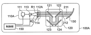
- FIG. 14 is a diagram showing a video display unit 110A in the virtual image display device 100A of the second embodiment.
- the video display unit 110A includes a light source unit 111, a polarization switching unit 112A, and a video generation unit 115.
- the polarization switching unit 112A will be described as a polarization switching element.
- the video generation unit 115 will be described with a configuration including a scanning unit 113 and a screen 114.
- the configurations of the light source unit 111, the scanning unit 113, and the screen 114 are as described in the first embodiment.
- the polarization switching element 112A is disposed adjacent to the incident side of the screen 114. “Adjacent” means being adjacent. Unlike the first embodiment, the polarization switching element 112 ⁇ / b> A is disposed between the scanning unit 113 and the screen 114. In FIG. 14, the polarization switching element 112 ⁇ / b> A is disposed in contact with the screen 114. The incident side of the screen 114 is the light source unit 111 side with respect to the screen 114.
- the polarization switching element 112A has substantially the same size as the screen 114.
- the polarization switching element 112 ⁇ / b> A is the same size as the screen 114.
- the size of the polarization switching element 112A does not have to be exactly the same as the size of the screen 114. The size may be such that all the light incident on the screen 114 passes through the polarization switching element 112A. That is, when the polarization switching element 112A has a size different from that of the screen 114, the polarization switching element 112A is smaller than the screen 114.
- the polarization switching element 112A is an element that can switch the polarization direction by applying a voltage, similarly to the polarization switching element 112 of the first embodiment. However, unlike the polarization switching element 112 of the first embodiment, the applied voltage can be controlled for each pixel.
- the polarization switching element 112 includes a switch that independently controls the presence / absence (on / off) of the voltage applied to the liquid crystal layer for each pixel, such as a general liquid crystal panel.
- the light passes through the first optical path 210 as shown in FIG.
- the light passes through the second optical path 220 as shown in FIG.
- FIG. 15 is a diagram illustrating an optical path of image light in the virtual image display device 100A according to the second embodiment.
- the virtual image display device 100A does not apply a voltage to the upper half area (non-voltage application area R1) of the polarization switching element 112A.
- the virtual image display device 100A applies a voltage to the lower half area (voltage application area R2) of the polarization switching element 112A.
- the light that has passed through the non-voltage application area R1 of the polarization switching element 112A passes through the first polarizing mirror 121 and the second polarizing mirror 122 and enters the magnifying mirror 130. That is, the light transmitted through the non-voltage application area R1 of the polarization switching element 112A passes through the first optical path 211.
- the light transmitted through the voltage application area R2 of the polarization switching element 112A is sequentially reflected by the first polarizing mirror 121, the first reflecting mirror 123, the second reflecting mirror 124, and the second polarizing mirror 122, The light enters the magnifying mirror 130. That is, the light transmitted through the voltage application area R2 of the polarization switching element 112A passes through the second optical path 221.
- the image A1 (first virtual image 410) is displayed at the first distance 411 (position e) close to the driver by the light passing through the first optical path 211.
- the image A ⁇ b> 2 (second virtual image 420) is displayed at a second distance 421 (position f) far from the driver by the light passing through the second optical path 221. That is, as shown in FIG. 13 described above, video A1 and video A2 are displayed simultaneously.
- the image displayed on the screen 114 is inverted in the vertical direction by the reflecting action of the magnifying mirror 130. Therefore, the image A1 (first virtual image 410) by the light passing through the non-voltage application area R1 in the upper half of the polarization switching element 112A is displayed on the lower side. An image A2 (second virtual image 420) by light passing through the voltage application area R2 in the lower half of the polarization switching element 112A is displayed on the upper side.
- the video A1 is information such as the traveling speed of the vehicle based on the information acquired from the traveling speed sensor 620 (FIG. 8), for example.
- the video A2 is, for example, a direction instruction arrow or alert information based on information acquired from the navigation system 630 (FIG. 9A).
- the image A1 (first virtual image 410) at the first distance 411 close to the driver can be clearly seen.
- the image A2 (second virtual image 420) at the second distance 421 far from the driver appears blurred to the driver.
- the video A2 (second virtual image 420) is clearly visible.
- the image A1 (first virtual image 410) appears blurred to the driver.
- the control unit 150 of the virtual image display device 100A performs control not to apply a voltage to the pixels corresponding to the upper half area (non-voltage application area R1) of the polarization switching element 112A. Then, the control unit 150 performs control to apply a voltage to the pixels corresponding to the lower half area (voltage application area R2) of the polarization switching element 112A.
- control unit 150 drives and controls the light source unit 111 and the scanning unit 113 so that the video A1 is displayed in the upper area of the screen 114.
- control unit 150 drives and controls the light source unit 111 and the scanning unit 113 so that the video A2 is displayed in the area below the screen 114.
- the applied voltage of the polarization switching element 112A is controlled for each pixel.
- the control is not limited to each pixel.
- the voltage applied to the polarization switching element 112A may be controlled for each area of the polarization switching element 112A.
- the applied voltage of the polarization switching element 112A is controlled in the upper half area and the lower half area of the polarization switching element 112A.
- the polarization switching element 112A switches the polarization direction for each area (for each pixel). Then, the virtual image display device 100A can simultaneously display virtual images at two positions e and f at different distances from the driver. Therefore, the driver can visually recognize different information depending on the position viewed by the driver.
- the light transmitted through the non-voltage application area R1 of the polarization switching element 112A passes through the first optical path 211.
- the light transmitted through the voltage application area R2 of the polarization switching element 112A passes through the second optical path 221.
- the light transmitted through the non-voltage application area R1 of the polarization switching element 112A passes through the second optical path 221 and the light transmitted through the voltage application area R2 of the polarization switching element 112A passes through the first optical path 211. It may be.
- the polarization switching element 112A is arranged on the incident side (light source unit 111 side) of the screen 114.
- the polarization switching element 112A may be arranged on the exit side of the screen 114 (the side opposite to the light source unit 111 side).
- the polarization switching element 112A converts the polarization direction of the image light formed by the scanning unit 113.
- a liquid crystal display unit can be used instead of the scanning unit 113 and the screen 114 (video generation unit 115).
- a liquid crystal display unit is arranged at the position of the screen 114 shown in FIG.
- the polarization switching element 112A is arranged at a position where the outgoing light (image light) of the liquid crystal display unit is incident.
- the light source unit 111 can be configured as a backlight of a liquid crystal display unit.
- DLP can be used instead of the scanning unit 113 and the screen 114 (video generation unit 115). That is, a DLP in which micromirrors are two-dimensionally arranged may be used instead of the liquid crystal display unit.
- all the light incident on the screen 114 is transmitted through the polarization switching element 112A (non-voltage application area R1 and voltage application area R2).
- the polarization switching element 112A non-voltage application area R1 and voltage application area R2.
- only light incident on a specific area of the screen 114 may be transmitted through the polarization switching element 112A.
- the specific area of the screen 114 is, for example, an area from 1/3 to 1/2 of the upper side of the screen 114.
- the polarization switching element may be capable of switching the voltage application for each pixel as described in the second embodiment. Further, as described in the first embodiment, the polarization switching element may be one that can switch the voltage application as a whole. By doing so, the virtual image display device 100A can switch the display distance of the virtual image of only the image of the necessary area on the screen 114.
- configuration example of the second embodiment may be combined with the configuration example (FIGS. 8 to 11) described in the first embodiment.
- FIG. 3 a virtual image display device 100B according to Embodiment 3 of the present invention will be described.
- the virtual image display device 100B according to the third embodiment is different from the virtual image display device 100 according to the first embodiment in the configuration of the optical path unit 120B, and the other parts are the same.
- the difference from the virtual image display apparatus 100 of Embodiment 1 is demonstrated.
- the same or corresponding elements as those of the virtual image display device 100 of the first embodiment are denoted by the same reference numerals, and the description thereof is omitted.
- the same components as the virtual image display device 100 of the first embodiment are the image display unit 110 (the light source unit 111, the polarization switching element 112, the scanning unit 113, and the screen 114), the first polarizing mirror 121, and the second polarizing mirror. 122, the first reflecting mirror 123, the second reflecting mirror 124, the magnifying mirror 130, and the control unit 150.
- the first reflection mirror 123 and the second reflection mirror 124 are different from the first embodiment in that they are mounted on the moving unit 127. That is, the first reflection mirror 123 and the second reflection mirror 124 are themselves the same as in the first embodiment.
- FIG. 16 illustrates a virtual image display device 100B according to the third embodiment.
- the optical path unit 120B of the virtual image display device 100B includes a moving unit 127 in addition to the optical path unit 120 described in the first embodiment.
- the moving unit 127 includes the first reflection mirror 123 and the second reflection mirror 124.
- the moving unit 127 is movable in the vertical direction.
- the vertical direction is the traveling direction of the light reflected at the center position of the first polarizing mirror 121.
- the virtual image display device 100B according to Embodiment 3 further includes a drive mechanism 160.
- the drive mechanism 160 moves the moving unit 127 in the vertical direction.
- the drive mechanism 160 is, for example, a combination of a feed screw and a motor.
- the drive mechanism 160 is not limited to one using a feed screw and a motor.
- the drive mechanism 160 only needs to be able to reciprocate the moving unit 127.
- the control unit 150 controls driving of the motor of the driving mechanism 160.
- the driving mechanism 160 moves the moving unit 127 in the vertical direction.
- the moving unit 127 includes the first reflection mirror 123 and the second reflection mirror 124. That is, the first reflection mirror 123 and the second reflection mirror 124 move in the vertical direction. As a result, the length of the optical path 220 changes.
- the optical path length of the second optical path 220 becomes longer. Then, the position f at which the second virtual image 420 is displayed moves in a direction away from the driver.
- the distance Ldv is a distance from the position d of the driver's eye 500 to the virtual image.
- the distance Lab is a distance from the position “a” of the screen 114 to the position “b” of the magnifying mirror 130.
- the distance Ldv is a distance from the position d of the driver's eye 500 to the virtual image.
- the position of the moving unit 127 is set so that the distance Ldv is 10 m or more when the moving unit 127 is at the reference position within the moving range.
- the reference position is, for example, the center position of the moving unit 127 in the moving direction.
- the display distance of the second virtual image 420 can be greatly moved by moving the moving unit 127 a little.
- the first reflection mirror 123 and the second reflection mirror 124 are moved by moving the moving unit 127.
- the virtual image display device 100B can adjust the display distance of the second virtual image 420.
- the display distance of the virtual image can be adjusted according to the real image.
- “Augmented Reality” is a technology for extending a real environment perceived by a person using a computer.
- AR display for example, a virtual image is superimposed on a real image.
- the virtual image display device 100B can adjust the display distance (second distance 421) of the second virtual image 420 according to the driver's preference.
- the first reflection mirror 123 and the second reflection mirror 124 mounted on the moving unit 127 are moved in the vertical direction.
- any configuration may be used as long as a part of the components of the optical path unit 120 is moved in the direction in which the optical path length of at least one of the first optical path 210 or the second optical path 220 is changed.
- first polarizing mirror 121 and the first reflecting mirror 123 may be moved in the front-rear direction (left-right direction in FIG. 16).
- second reflecting mirror 124 and the second polarizing mirror 122 may be moved in the front-rear direction.
- the screen 114 may be moved in the front-rear direction (the traveling direction of the laser light transmitted through the center position of the second polarizing mirror 122). Further, the entire video display unit 110 may be moved in the front-rear direction.
- the optical path lengths of both the first optical path 210 and the second optical path 220 can be adjusted. For this reason, it is possible to adjust both the position e where the first virtual image 410 is displayed and the position f where the second virtual image 420 is displayed.
- the third embodiment may be combined with the configuration example (FIGS. 8 to 11) described in the first embodiment or the second embodiment.
- Embodiment 4 FIG. Next, a virtual image display device 100C according to Embodiment 4 of the present invention will be described.
- the virtual image display device 100C according to the fourth embodiment is different from the virtual image display device 100 according to the first embodiment in the configuration of the optical path unit 120C, and the other parts are the same.
- the difference from the virtual image display apparatus 100 of Embodiment 1 is demonstrated.
- the same or corresponding elements as those of the virtual image display device 100 of the first embodiment are denoted by the same reference numerals, and the description thereof is omitted.
- the same components as the virtual image display device 100 of the first embodiment are the image display unit 110 (the light source unit 111, the polarization switching element 112, the scanning unit 113, and the screen 114), the polarizing mirror 121, the magnifying mirror 130, and the control unit 150. is there.
- FIG. 17 is a diagram showing a virtual image display device 100C according to the fourth embodiment.
- the optical path unit 120C of the virtual image display device 100C according to Embodiment 4 includes a polarizing mirror 121, a first quarter-wave plate 125a, a second quarter-wave plate 125b, and a first mirror 126a as a polarization separation element. And a second mirror 126b.
- the polarizing mirror 121 is the same as the polarizing mirror 121 in the optical path unit 120 described in the first embodiment.
- the polarizing mirror 121 is disposed at a position where the image light from the image display unit 110 is incident.
- the first quarter-wave plate 125 a and the first mirror 126 a are disposed on the optical axis where incident light is reflected by the polarizing mirror 121.
- the second quarter-wave plate 125b and the second mirror 126b are disposed on the opposite side of the first quarter-wave plate 125a and the first mirror 126a with the polarizing mirror 121 interposed therebetween.
- the polarizing mirror 121 has characteristics of transmitting p-polarized light and reflecting s-polarized light will be described.
- the light incident on the optical path unit 120C enters the polarizing mirror 121.
- the light incident on the polarizing mirror 121 is p-polarized light
- the light incident on the polarizing mirror 121 passes through the polarizing mirror 121 and passes through the first optical path 210.
- the virtual image 410 is displayed at the position e.
- the first optical path 210 is an optical path that passes through the polarizing mirror 121.
- the second optical path 220 includes, for example, the following optical paths (1), (2), and (3).
- (1) The light that has entered the polarizing mirror 121 is reflected by the polarizing mirror 121, passes through the first quarter-wave plate 125a, is reflected by the first mirror 126a, and then again the first 1/4. The light passes through the wave plate 125a and enters the polarizing mirror 121 again.
- the reason why the second optical path 220 is as described above will be described.
- the light incident on the polarizing mirror 121 is s-polarized light, it is first reflected by the polarizing mirror 121.
- the light reflected by the polarizing mirror 121 travels downward in FIG.
- the light traveling downward in FIG. 17 reaches the first quarter-wave plate 125a.
- the s-polarized light (linearly polarized light) transmitted through the first quarter-wave plate 125a is converted into circularly polarized light having a phase difference of 90 degrees.
- the circularly polarized light reaches the first mirror 126a.
- the first mirror 126a reflects the circularly polarized light as it is.
- the circularly polarized light reflected by the first mirror 126a passes through the first quarter-wave plate 125a again, and a phase difference of 90 degrees is further added. Then, the light transmitted through the first quarter-wave plate 125a again is converted from circularly polarized light to linearly polarized light. As a result, the light incident on the polarizing mirror 121 again with respect to the light incident on the polarizing mirror 121 (s-polarized light) first is converted into p-polarized light having a phase difference of 180 degrees and a polarization direction rotated by 90 degrees. It will be.
- the light converted into p-polarized light by reciprocating the first quarter-wave plate 125a passes through the polarizing mirror 121 and travels upward in FIG.
- the light transmitted through the polarizing mirror 121 reaches the second quarter wavelength plate 125b.
- the light transmitted through the polarizing mirror 121 is transmitted through the second quarter-wave plate 125 b, converted into circularly polarized light having a phase difference of 90 degrees, and reflected by the second mirror 126.
- the circularly polarized light reflected by the second mirror 126b passes through the second quarter-wave plate 125b again and is converted to s-polarized light.
- the light that has returned to the polarizing mirror 121 again is reflected by the polarizing mirror 121 and travels toward the magnifying mirror 130.
- the virtual image display device 100C Since it is configured as described above, the virtual image display device 100C according to the fourth embodiment has the following characteristics as compared with the first to third embodiments.
- the optical path unit 120C has only one polarizing mirror which is a special optical component.
- the optical path unit 120C can be configured with a small space, and the virtual image display device 100C can be miniaturized.
- the second optical path 220 is an optical path having a long optical path length.
- first mirror 126a or the second mirror 126b may be fixed. Further, the first mirror 126a or the second mirror 126b may be moved. In the configuration in which the first mirror 126a or the second mirror 126b is moved, the first mirror 126a or the second mirror 126b is moved in the vertical direction in FIG. Thereby, the position g of the virtual image 430 can be changed.
- both the first mirror 126a and the second mirror 126b may be moved in opposite directions.
- first quarter-wave plate 125a and the first mirror 126a may be moved together.
- second quarter-wave plate 125b and the second mirror 126b may be moved together.
- FIG. 18 is a diagram illustrating a modification of the configuration of the virtual image display device according to the fourth embodiment.
- the virtual image display device 100D of the modification shown in FIG. 18 further includes an optical path unit 120D in addition to the optical path unit 120C.
- the optical path unit 120D has the same configuration as the optical path unit 120C except for the optical path length.
- the virtual image display device 100D includes a second polarization switching unit 128 between the optical path unit 120C and the optical path unit D.
- the second optical path 220 has different optical path lengths for the optical path unit 120C and the optical path unit 120D.
- the second optical path 220 is an optical path having a longer optical path length in the optical path unit.
- FIG. 18 shows a case where the optical path length of the optical path unit 120D is shorter than the optical path length of the optical path unit 120C.
- the optical path unit 120C is disposed at a position where the image light from the image display unit 110 is incident.
- the second polarization switching unit 128 is disposed at a position where light emitted from the optical path unit 120C enters.
- the optical path unit 120D is disposed at a position where the light emitted from the second polarization switching unit 128 enters.
- the second polarization switching unit 128 is configured to be able to switch between emitting light without changing the polarization direction of incident light or changing the polarization direction by 90 degrees.
- the second polarization switching unit 128 is controlled by the control unit 150. In FIG. 18, the arrow from the control unit 150 to the second polarization switching unit 128 is omitted.
- the light incident on the optical path unit 120C passes through the first optical path 210. That is, the light incident on the optical path unit 120C passes through the short optical path of the optical path unit 120C and the short optical path of the optical path unit D. Then, the virtual image 410 is displayed at the position e.
- the light emitted from the optical path unit 120C cannot be switched in polarization by the second polarization switching unit 128. That is, the light emitted from the optical path unit 120C is incident on the optical path unit 120D as p-polarized light.
- the second optical path 220 has three optical path lengths. That is, the virtual image 440 is displayed at the position h, the virtual image 430 is displayed at the position g, and the virtual image 450 is displayed at the position i.
- the virtual image 440 is displayed farther than the virtual image 410.
- the virtual image 430 is displayed farther than the virtual image 440.
- the virtual image 450 is displayed farther than the virtual image 430.
- the virtual image 440 displayed at the position h will be described.
- the light from the screen 114 is p-polarized light
- the second polarization switching unit 128 changes the polarization direction of the incident light by 90 degrees.
- the light incident on the optical path unit 120C passes through the short optical path (first optical path 210) of the optical path unit 120C.
- the light emitted from the optical path unit 120C is switched from p-polarized light to s-polarized light by the second polarization switching unit 128.
- the light switched to the s-polarized light passes through the long optical path (second optical path 220) of the optical path unit 120D.
- the virtual image 440 is displayed at the position h by the light emitted from the optical path unit 120D.
- the virtual image 430 displayed at the position g will be described.
- the light from the screen 114 is s-polarized light
- the second polarization switching unit 128 changes the polarization direction of the incident light by 90 degrees.
- the light incident on the optical path unit 120C passes through the long optical path (second optical path 220) of the optical path unit C.
- the light emitted from the optical path unit 120C is switched from s-polarized light to p-polarized light by the second polarization switching unit 128.
- the light switched to the p-polarized light passes through the short optical path (first optical path 210) of the optical path unit 120D.
- the virtual image 430 is displayed at the position g by the light emitted from the optical path unit 120D.
- the virtual image 450 displayed at the position i will be described.
- the light from the screen 114 is s-polarized light, and the second polarization switching unit 128 does not change the polarization direction of the incident light.
- the light incident on the optical path unit 120C passes through a long optical path (second optical path 220) of the optical path unit 120C.
- the polarization direction of the light emitted from the optical path unit 120C is not changed by the second polarization switching unit 128. That is, the light emitted from the optical path unit 120C enters the optical path unit 120D as s-polarized light.
- the light incident on the optical path unit 120D passes through the long optical path (second optical path 220) of the optical path unit 120D.
- the virtual image 450 is displayed at the position i by the light emitted from the optical path unit 120D.
- the quarter-wave plates 125 a and 125 b and the mirrors 126 a and 126 b are arranged in the vertical direction of the polarizing mirror 121.
- the arrangement is not limited to this.
- the quarter wave plates 125 a and 125 b and the mirrors 126 a and 126 b may be arranged in the lateral direction of the polarizing mirror 121.
- the distance from the first polarizing mirror 121 to the first mirror 126a is the same as the distance from the first polarizing mirror 121 to the second mirror 126b. Yes.
- a configuration in which one of the distances is increased may be used.
- it can be arranged at an asymmetrical distance according to the space of the dashboard of an automobile. Thereby, the freedom degree which installs a virtual image display apparatus improves compared with the structure from Embodiment 1 to 3.
- the fourth embodiment may be combined with the first embodiment (FIGS. 1 to 7), the configuration example (FIGS. 8 to 11), the second embodiment, or the third embodiment.
- Embodiment 5 FIG. Next, a virtual image display device 100E according to Embodiment 5 of the present invention will be described.
- the virtual image display device 100E according to Embodiment 5 is a head mounted display attached to, for example, glasses.
- the virtual image display device 100E according to the fifth embodiment has the same basic configuration as the first embodiment. Below, the difference from the virtual image display apparatus 100 of Embodiment 1 is demonstrated. The same or corresponding elements as those in the virtual image display device 100 of the first embodiment are denoted by the same reference numerals.
- FIG. 19 is a view of a glasses-type head-mounted display as viewed from the top as the virtual image display device 100E according to the fifth embodiment.
- the virtual image display device 100E according to Embodiment 5 is installed in the glasses 700.
- Video light from the video display unit 110 passes through either the optical path 210 or the optical path 220 and is reflected by the mirror 131 toward the lens of the glasses 700.
- the image light reflected by the mirror 131 is reflected by the mirror 301 incorporated in the lens portion of the spectacles 700, and the virtual image 410 or the virtual image 420 can be visually recognized from the person wearing the spectacles 700.
- the control unit 150 (FIG. 1) is omitted.
- the mirror 301 corresponds to the front window 300 (FIG. 1) of the first embodiment.
- image light is reflected in the direction of the eye (left eye) 500L by a transmissive free-form surface mirror.
- the mirror 301 is not limited to a free-form surface mirror.
- a hologram element or a diffraction element that can control the light diffraction angle to a desired angle may be used.
- the optical path 210 and the optical path 220 through which the image light passes can be switched.
- the virtual image 410 can be visually recognized at a position close to the eye (left eye) 500L.
- the virtual image 420 can be visually recognized at a position far from the eye (left eye) 500L.
- the head-mounted display displays information and video superimposed on the background as work support video display. For this reason, if the difference between the distance from the eyes to the virtual image (information) and the distance from the eyes to the background is large, the visibility decreases. Moreover, it makes it easy to fatigue an operator. Therefore, for example, the distance to the background when information is superimposed is separately measured, and switching between displaying a virtual image at a short distance or displaying a virtual image at a long distance is performed.
- the distance for displaying the virtual image is switched in the head mounted display. For this reason, it is possible to reduce a distance difference between information superimposed on the background and video. And visibility improvement and a worker's fatigue reduction are attained.
- the virtual image display device 100D is attached to the left eye 500L side.
- the virtual image display device 100D may be attached to the right eye 500R side in the same manner.
- the virtual image display device 100D may be attached to both the left eye 500L side and the right eye side 500R.
- the virtual image display devices 100, 100A, 100B, 100C, 100D, and 100E described above can be used as, for example, a head-up display or a head-mounted display for an automobile or the like. Further, the virtual image display devices 100, 100A, 100B, 100C, 100D, and 100E can be used not only in automobiles but also in various fields that use airplanes, medical fields, or virtual images.
- 100, 100A, 100B, 100C, 100D, 100E virtual image display device 110, 110A video display unit, 111 light source unit, 11R, 11G, 11B semiconductor laser, 11a, 11b, 11c mirror, 112, 112A polarization switching element, 113 scanning Unit, 113a scanning mirror, 114 screen, 115 video generation unit, 120, 120B, 120C optical path unit, 121 first polarizing mirror, 122 second polarizing mirror, 123 first reflecting mirror, 124 second reflecting mirror, 125 half mirror, 125a first quarter wave plate, 125b second quarter wave plate, 126a first mirror, 126b second mirror, 126 polarizing plate, 127 moving part, 128 second Polarization switching unit, 130 magnifying mirror, 150 control unit, 160 drive mechanism, 210, 211, first optical path, 220, 221, second optical path, 300 front window, 410, first virtual image, 411, first distance, 420th 2 virtual images, 421 2nd distance, 500 driver's eyes, 600 vehicles.
Landscapes
- Physics & Mathematics (AREA)
- Optics & Photonics (AREA)
- Engineering & Computer Science (AREA)
- General Physics & Mathematics (AREA)
- Multimedia (AREA)
- Signal Processing (AREA)
- Chemical & Material Sciences (AREA)
- Combustion & Propulsion (AREA)
- Transportation (AREA)
- Mechanical Engineering (AREA)
- Instrument Panels (AREA)
- Mechanical Optical Scanning Systems (AREA)
Abstract
Priority Applications (4)
| Application Number | Priority Date | Filing Date | Title |
|---|---|---|---|
| JP2016527670A JP6271006B2 (ja) | 2014-06-13 | 2015-03-26 | 虚像表示装置 |
| DE112015002814.5T DE112015002814B4 (de) | 2014-06-13 | 2015-03-26 | Anzeigevorrichtung für virtuelle Bilder |
| US15/310,399 US10254551B2 (en) | 2014-06-13 | 2015-03-26 | Virtual image display device |
| CN201580031269.9A CN106471417B (zh) | 2014-06-13 | 2015-03-26 | 虚像显示装置以及车辆的头戴式显示器 |
Applications Claiming Priority (2)
| Application Number | Priority Date | Filing Date | Title |
|---|---|---|---|
| JP2014-121944 | 2014-06-13 | ||
| JP2014121944 | 2014-06-13 |
Publications (1)
| Publication Number | Publication Date |
|---|---|
| WO2015190157A1 true WO2015190157A1 (fr) | 2015-12-17 |
Family
ID=54833266
Family Applications (1)
| Application Number | Title | Priority Date | Filing Date |
|---|---|---|---|
| PCT/JP2015/059302 WO2015190157A1 (fr) | 2014-06-13 | 2015-03-26 | Dispositif d'affichage d'image virtuelle |
Country Status (5)
| Country | Link |
|---|---|
| US (1) | US10254551B2 (fr) |
| JP (1) | JP6271006B2 (fr) |
| CN (1) | CN106471417B (fr) |
| DE (1) | DE112015002814B4 (fr) |
| WO (1) | WO2015190157A1 (fr) |
Cited By (53)
| Publication number | Priority date | Publication date | Assignee | Title |
|---|---|---|---|---|
| JP2016212338A (ja) * | 2015-05-13 | 2016-12-15 | 日本精機株式会社 | ヘッドアップディスプレイ |
| JP2017076044A (ja) * | 2015-10-14 | 2017-04-20 | ホシデン株式会社 | レーザ光を用いた投射型表示装置及び該投射型表示装置を用いた車載用ヘッドアップディスプレイ |
| CN106814458A (zh) * | 2017-02-13 | 2017-06-09 | 惠州市华阳多媒体电子有限公司 | 一种增强现实抬头显示器 |
| JP2017129754A (ja) * | 2016-01-20 | 2017-07-27 | パナソニックIpマネジメント株式会社 | 表示装置 |
| WO2017163288A1 (fr) * | 2016-03-24 | 2017-09-28 | パナソニックIpマネジメント株式会社 | Dispositif d'affichage tête haute et véhicule |
| WO2017170702A1 (fr) * | 2016-03-30 | 2017-10-05 | 三菱電機株式会社 | Dispositif d'affichage tête haute |
| JP2018017750A (ja) * | 2016-07-25 | 2018-02-01 | 富士フイルム株式会社 | ヘッドアップディスプレイ装置 |
| WO2018031963A1 (fr) | 2016-08-12 | 2018-02-15 | Avegant Corp. | Système d'affichage proche de l'oeil comprenant un empilement de modulation |
| WO2018031965A1 (fr) * | 2016-08-12 | 2018-02-15 | Avegant Corp. | Modulation numérique de longueur de trajet de lumière |
| WO2018031964A1 (fr) * | 2016-08-12 | 2018-02-15 | Avegant Corp. | Systèmes de modulation de longueur de trajet de lumière numérique |
| DE102017202228A1 (de) | 2017-02-13 | 2018-03-15 | Volkswagen Aktiengesellschaft | Head-UP-Display-Vorrichtung für ein Kraftfahrzeug, Verfahren, Vorrichtung und Computerlesbares Speichermedium mit Instruktionen zur Steuerung einer Anzeige einer Head-Up-Display-Vorrichtung |
| JP2018072598A (ja) * | 2016-10-31 | 2018-05-10 | 株式会社ジャパンディスプレイ | 表示装置 |
| WO2018116778A1 (fr) * | 2016-12-21 | 2018-06-28 | パナソニックIpマネジメント株式会社 | Dispositif d'affichage d'image virtuelle |
| CN108241209A (zh) * | 2016-12-23 | 2018-07-03 | 怡利电子工业股份有限公司 | 多重显示抬头显示设备 |
| WO2018135056A1 (fr) * | 2017-01-23 | 2018-07-26 | 浜松ホトニクス株式会社 | Dispositif d'affichage |
| US10057488B2 (en) | 2016-08-12 | 2018-08-21 | Avegant Corp. | Image capture with digital light path length modulation |
| DE102017104835A1 (de) | 2017-03-08 | 2018-09-13 | Dr. Ing. H.C. F. Porsche Aktiengesellschaft | Bilderzeugungseinheit für ein Head-up-Display |
| WO2018168708A1 (fr) * | 2017-03-14 | 2018-09-20 | パイオニア株式会社 | Dispositif d'affichage |
| WO2018167314A1 (fr) * | 2017-03-17 | 2018-09-20 | Valeo Comfort And Driving Assistance | Afficheur tête haute adapté au port de lunettes polarisantes |
| JP2018146950A (ja) * | 2017-03-02 | 2018-09-20 | 株式会社リコー | 表示装置及び機器 |
| US10185153B2 (en) | 2016-08-12 | 2019-01-22 | Avegant Corp. | Orthogonal optical path length extender |
| JP2019032362A (ja) * | 2017-08-04 | 2019-02-28 | アルパイン株式会社 | ヘッドアップディスプレイ装置、ナビゲーション装置 |
| CN109643021A (zh) * | 2016-08-29 | 2019-04-16 | 麦克赛尔株式会社 | 平视显示装置 |
| JPWO2017221945A1 (ja) * | 2016-06-20 | 2019-05-23 | 京セラ株式会社 | 表示装置、表示システム、移動体、および表示方法 |
| CN109932819A (zh) * | 2017-12-18 | 2019-06-25 | 深圳点石创新科技有限公司 | 抬头显示器 |
| CN110036334A (zh) * | 2016-08-12 | 2019-07-19 | 阿维甘特公司 | 数字光路长度调制 |
| CN110337606A (zh) * | 2017-02-28 | 2019-10-15 | 京瓷株式会社 | 室外用图像照射装置及具备其的移动体 |
| US10516879B2 (en) | 2016-08-12 | 2019-12-24 | Avegant Corp. | Binocular display with digital light path length modulation |
| WO2020021773A1 (fr) * | 2018-07-23 | 2020-01-30 | 株式会社Jvcケンウッド | Dispositif d'affichage d'image virtuelle |
| EP3465330A4 (fr) * | 2016-05-23 | 2020-03-04 | LG Electronics Inc. -1- | Affichage tête haute pour véhicule |
| JP2020037351A (ja) * | 2018-09-05 | 2020-03-12 | マクセル株式会社 | ヘッドアップディスプレイ装置 |
| WO2020080355A1 (fr) | 2018-10-17 | 2020-04-23 | 富士フイルム株式会社 | Élément d'affichage d'image à projection, vitre de pare-brise, et système d'affichage tête haute |
| WO2020122023A1 (fr) | 2018-12-10 | 2020-06-18 | 富士フイルム株式会社 | Élément d'affichage d'image de projection, vitre de pare-brise et système d'affichage tête haute |
| JP2020522010A (ja) * | 2017-05-29 | 2020-07-27 | アイウェイ ビジョン リミテッドEyeWay Vision Ltd. | 焦点合わせ管理を伴う眼の投影システム、及び、方法 |
| US10809546B2 (en) | 2016-08-12 | 2020-10-20 | Avegant Corp. | Digital light path length modulation |
| JP2021120750A (ja) * | 2016-12-15 | 2021-08-19 | デュアリタス リミテッド | 車載用表示装置 |
| WO2021200652A1 (fr) | 2020-03-30 | 2021-10-07 | 富士フイルム株式会社 | Film de réflexion de lumière à polarisation linéaire, verre de pare-brise et système d'affichage tête haute |
| WO2021200655A1 (fr) | 2020-03-30 | 2021-10-07 | 富士フイルム株式会社 | Film réfléchissant, verre de pare-brise et système d'affichage tête haute |
| JP2021529332A (ja) * | 2018-06-29 | 2021-10-28 | 京東方科技集團股▲ふん▼有限公司Boe Technology Group Co.,Ltd. | ヘッドアップ表示装置及びその表示方法 |
| WO2021246402A1 (fr) | 2020-06-03 | 2021-12-09 | 富士フイルム株式会社 | Film réfléchissant, procédé de production de verre feuilleté et verre feuilleté |
| JP2022023860A (ja) * | 2016-03-02 | 2022-02-08 | フェイスブック・テクノロジーズ・リミテッド・ライアビリティ・カンパニー | 像面湾曲補正ディスプレイ |
| JP2022044194A (ja) * | 2020-09-07 | 2022-03-17 | 創智車電股▲ふん▼有限公司 | 異なる距離の虚像を利用する、車両用ヘッドアップ表示システム |
| US11287649B2 (en) * | 2018-11-09 | 2022-03-29 | Boe Technology Group Co., Ltd. | Display device and display method |
| WO2022075184A1 (fr) | 2020-10-09 | 2022-04-14 | 富士フイルム株式会社 | Film réfléchissant, verre de pare-brise et système d'affichage tête haute |
| WO2022123946A1 (fr) | 2020-12-09 | 2022-06-16 | 富士フイルム株式会社 | Film de réflexion, verre de pare-brise et système d'affichage tête haute |
| US11402633B2 (en) * | 2018-03-28 | 2022-08-02 | Boe Technology Group Co., Ltd. | Head-up display device, method for controlling the same, and vehicle |
| EP4086690A1 (fr) * | 2016-12-02 | 2022-11-09 | LG Electronics Inc. | Affichage tête haute pour véhicule |
| WO2022270222A1 (fr) | 2021-06-21 | 2022-12-29 | 富士フイルム株式会社 | Système de projection d'images |
| WO2023054324A1 (fr) | 2021-09-30 | 2023-04-06 | 富士フイルム株式会社 | Système d'affichage tête haute et transport |
| WO2023074288A1 (fr) * | 2021-10-26 | 2023-05-04 | 矢崎総業株式会社 | Dispositif d'affichage pour véhicule |
| WO2023080115A1 (fr) | 2021-11-05 | 2023-05-11 | 富士フイルム株式会社 | Dispositif d'affichage d'image virtuelle, système d'affichage tête haute, et engin de transport |
| WO2024014202A1 (fr) * | 2022-07-15 | 2024-01-18 | ソニーグループ株式会社 | Système optique et dispositif d'affichage |
| JP7490820B2 (ja) | 2020-05-15 | 2024-05-27 | 華為技術有限公司 | 多焦点画像生成装置、ヘッドアップディスプレイ装置、関連する方法およびデバイス |
Families Citing this family (52)
| Publication number | Priority date | Publication date | Assignee | Title |
|---|---|---|---|---|
| US20110187878A1 (en) | 2010-02-02 | 2011-08-04 | Primesense Ltd. | Synchronization of projected illumination with rolling shutter of image sensor |
| JP6485732B2 (ja) * | 2014-12-10 | 2019-03-20 | 株式会社リコー | 情報提供装置、情報提供方法及び情報提供用制御プログラム |
| JP6451523B2 (ja) * | 2015-06-17 | 2019-01-16 | 株式会社デンソー | ヘッドアップディスプレイ装置 |
| JP6489371B2 (ja) * | 2015-07-01 | 2019-03-27 | パナソニックIpマネジメント株式会社 | 表示装置 |
| US9823472B2 (en) * | 2015-07-17 | 2017-11-21 | Lg Electronics Inc. | Head up display for vehicle |
| CN105150935A (zh) * | 2015-08-19 | 2015-12-16 | 京东方科技集团股份有限公司 | 平视显示器、平视显示方法以及车载显示装置 |
| CN108139584B (zh) * | 2015-10-15 | 2020-08-28 | 麦克赛尔株式会社 | 信息显示装置 |
| US10031336B2 (en) * | 2016-01-26 | 2018-07-24 | Panasonic Intellectual Property Management Co., Ltd. | Image display device |
| CN108473055B (zh) * | 2016-02-05 | 2021-02-26 | 麦克赛尔株式会社 | 平视显示器装置 |
| JP6817088B2 (ja) * | 2017-01-26 | 2021-01-20 | 矢崎総業株式会社 | 表示装置、及び、表示装置本体 |
| JP6692939B2 (ja) * | 2017-02-15 | 2020-05-13 | マクセル株式会社 | ヘッドアップディスプレイ装置 |
| WO2018186709A1 (fr) * | 2017-04-06 | 2018-10-11 | 엘지전자 주식회사 | Appareil d'affichage tête haute pour véhicule |
| US10726574B2 (en) * | 2017-04-11 | 2020-07-28 | Dolby Laboratories Licensing Corporation | Passive multi-wearable-devices tracking |
| CN109143576B (zh) * | 2017-06-27 | 2021-01-22 | 京东方科技集团股份有限公司 | 显示系统及其显示方法、交通工具 |
| DE102017211691A1 (de) * | 2017-07-07 | 2019-01-10 | Bayerische Motoren Werke Aktiengesellschaft | Blickfeldanzeigevorrichtung für ein Fahrzeug |
| CN107238936A (zh) * | 2017-07-11 | 2017-10-10 | 京东方科技集团股份有限公司 | 立体显示装置、系统及立体显示方法 |
| CA3013888A1 (fr) * | 2017-08-11 | 2019-02-11 | Jason Carl Radel | Affichage d'image aerienne transmissible |
| JP6663890B2 (ja) * | 2017-09-06 | 2020-03-13 | 矢崎総業株式会社 | バックライトユニットおよびヘッドアップディスプレイ装置 |
| DE102017216466A1 (de) * | 2017-09-18 | 2019-03-21 | Bayerische Motoren Werke Aktiengesellschaft | Blickfeldanzeigevorrichtung für ein Fahrzeug |
| CN109991744B (zh) * | 2018-01-02 | 2020-12-01 | 京东方科技集团股份有限公司 | 显示装置、显示方法及平视显示装置 |
| US11378800B2 (en) | 2018-01-11 | 2022-07-05 | Samsung Electronics Co., Ltd. | Image display apparatus |
| US10447424B2 (en) | 2018-01-18 | 2019-10-15 | Apple Inc. | Spatial multiplexing scheme |
| JP7126115B2 (ja) * | 2018-01-31 | 2022-08-26 | パナソニックIpマネジメント株式会社 | 表示システム、移動体、及び、設計方法 |
| US10877285B2 (en) | 2018-03-28 | 2020-12-29 | Apple Inc. | Wavelength-based spatial multiplexing scheme |
| CN108398791B (zh) * | 2018-03-29 | 2022-11-25 | 陈超平 | 一种基于偏光隐形眼镜的近眼显示装置 |
| CN108761789B (zh) * | 2018-05-24 | 2020-03-10 | 京东方科技集团股份有限公司 | 抬头显示器及汽车 |
| JP7042443B2 (ja) * | 2018-06-21 | 2022-03-28 | パナソニックIpマネジメント株式会社 | 映像表示システム、映像表示方法、プログラム、及び移動体 |
| JP6877643B2 (ja) * | 2018-06-22 | 2021-05-26 | 三菱電機株式会社 | 映像表示装置 |
| CN108919494B (zh) * | 2018-08-01 | 2021-02-02 | 张家港康得新光电材料有限公司 | 一种抬头显示装置及汽车 |
| GB2576738B (en) * | 2018-08-29 | 2020-08-19 | Envisics Ltd | Head-up display |
| US11493606B1 (en) | 2018-09-12 | 2022-11-08 | Apple Inc. | Multi-beam scanning system |
| CN109100866A (zh) * | 2018-10-22 | 2018-12-28 | 萤欧(上海)汽车科技有限公司 | 一种基于液晶偏振方向旋转器的车载ar-hud光学系统 |
| JP7105173B2 (ja) * | 2018-11-02 | 2022-07-22 | 京セラ株式会社 | 3次元表示装置、ヘッドアップディスプレイ、移動体、およびプログラム |
| US11002970B2 (en) * | 2019-02-06 | 2021-05-11 | Google Llc | Multi-focal catadioptric head mounted display with LC switch |
| DE102019001559A1 (de) | 2019-03-06 | 2019-09-19 | Daimler Ag | Vorrichtung und Verfahren zur Einstellung der Polarisationsrichtung eines Head-UP-Displays |
| CN110161693A (zh) * | 2019-05-06 | 2019-08-23 | 苏州佳世达光电有限公司 | 成像系统 |
| CN110275154B (zh) * | 2019-07-05 | 2021-11-02 | 哈尔滨工业大学 | 一种激光雷达偏振探测光学调节机构 |
| US20230014232A1 (en) * | 2019-12-05 | 2023-01-19 | Koito Manufacturing Co., Ltd. | Image displaying device |
| CN114063290A (zh) * | 2020-08-07 | 2022-02-18 | 东莞创奕电子科技有限公司 | 车用抬头显示系统 |
| US20220055479A1 (en) * | 2020-08-24 | 2022-02-24 | Conserve & Associates , Inc. | Vehicular head-up display system with virtual images in different distances |
| TWI738486B (zh) * | 2020-09-01 | 2021-09-01 | 創智車電股份有限公司 | 具有雙虛像距離的車用抬頭顯示系統 |
| US20220163919A1 (en) * | 2020-11-23 | 2022-05-26 | GM Global Technology Operations LLC | Micromirror pixel design to eliminate intensity artifacts in holographic displays |
| CN112630879B (zh) * | 2020-12-25 | 2022-09-30 | 中国工程物理研究院激光聚变研究中心 | 一种相位延迟元件及相位延迟装置 |
| CN112578567A (zh) * | 2020-12-28 | 2021-03-30 | 广景视睿科技(深圳)有限公司 | 一种投影光学系统及汽车的抬头显示装置 |
| CN112558308A (zh) * | 2020-12-28 | 2021-03-26 | 广景视睿科技(深圳)有限公司 | 一种投影光学系统及汽车的抬头显示装置 |
| CN112578566A (zh) * | 2020-12-28 | 2021-03-30 | 广景视睿科技(深圳)有限公司 | 一种投影光学系统及汽车的抬头显示装置 |
| CN115113394A (zh) * | 2021-03-23 | 2022-09-27 | 群创光电股份有限公司 | 抬头显示系统 |
| JP2022179358A (ja) * | 2021-05-21 | 2022-12-02 | 中強光電股▲ふん▼有限公司 | ヘッドアップ表示装置 |
| CN113391451B (zh) * | 2021-06-30 | 2022-11-15 | 上海天马微电子有限公司 | 一种显示装置及汽车 |
| CN114089532A (zh) * | 2021-11-19 | 2022-02-25 | 业成科技(成都)有限公司 | 显示器系统 |
| CN115629475A (zh) * | 2022-01-30 | 2023-01-20 | 华为技术有限公司 | 显示装置和交通工具 |
| CN114647089A (zh) * | 2022-04-12 | 2022-06-21 | 业成科技(成都)有限公司 | 抬头显示器及车辆 |
Citations (9)
| Publication number | Priority date | Publication date | Assignee | Title |
|---|---|---|---|---|
| JP2004168230A (ja) * | 2002-11-21 | 2004-06-17 | Nissan Motor Co Ltd | 車両用表示装置 |
| JP2007524117A (ja) * | 2004-01-09 | 2007-08-23 | コーニンクレッカ フィリップス エレクトロニクス エヌ ヴィ | 光路長アジャスター |
| JP2009248847A (ja) * | 2008-04-09 | 2009-10-29 | Toyota Motor Corp | 車両用表示装置 |
| JP2009280142A (ja) * | 2008-05-23 | 2009-12-03 | Mitsubishi Electric Corp | 車載インパネ画像表示装置 |
| JP2012037761A (ja) * | 2010-08-09 | 2012-02-23 | Sony Corp | 表示装置組立体 |
| JP2013190957A (ja) * | 2012-03-13 | 2013-09-26 | Toyota Motor Corp | 周辺監視装置及び周辺監視方法 |
| JP2013214008A (ja) * | 2012-04-04 | 2013-10-17 | Mitsubishi Electric Corp | 表示装置及びこれを備えたヘッドアップディスプレイシステム |
| JP2013235256A (ja) * | 2012-04-10 | 2013-11-21 | Panasonic Corp | 計算機ホログラム型表示装置 |
| WO2014208330A1 (fr) * | 2013-06-28 | 2014-12-31 | アイシン・エィ・ダブリュ株式会社 | Dispositif d'affichage tête haute |
Family Cites Families (15)
| Publication number | Priority date | Publication date | Assignee | Title |
|---|---|---|---|---|
| US6639706B2 (en) * | 2001-01-24 | 2003-10-28 | Kollsman, Inc. | Optical path switch and method of using thereof |
| US6522474B2 (en) * | 2001-06-11 | 2003-02-18 | Eastman Kodak Company | Head-mounted optical apparatus for stereoscopic display |
| US6950173B1 (en) * | 2003-04-08 | 2005-09-27 | Science Applications International Corporation | Optimizing performance parameters for switchable polymer dispersed liquid crystal optical elements |
| GB0403933D0 (en) | 2004-02-21 | 2004-03-24 | Koninkl Philips Electronics Nv | Optical path length adjuster |
| JP2008257021A (ja) | 2007-04-06 | 2008-10-23 | Nippon Seiki Co Ltd | 表示装置 |
| JP2009015128A (ja) | 2007-07-06 | 2009-01-22 | Alpine Electronics Inc | 立体画像表示装置 |
| JP2009015094A (ja) | 2007-07-06 | 2009-01-22 | Hitachi Kokusai Electric Inc | 撮像装置 |
| JP2009150947A (ja) | 2007-12-19 | 2009-07-09 | Hitachi Ltd | 車両用ヘッドアップディスプレイ装置 |
| JP2009288388A (ja) | 2008-05-28 | 2009-12-10 | Nippon Seiki Co Ltd | 表示装置 |
| JP2010107545A (ja) * | 2008-10-28 | 2010-05-13 | Panasonic Corp | 画像表示装置 |
| DE102010002956A1 (de) | 2010-03-17 | 2011-09-22 | Robert Bosch Gmbh | Head-up Display für Fahrzeuge |
| JP5723123B2 (ja) * | 2010-09-13 | 2015-05-27 | 矢崎総業株式会社 | ヘッドアップディスプレイ |
| JP5423742B2 (ja) * | 2011-08-27 | 2014-02-19 | 株式会社デンソー | ヘッドアップディスプレイ装置 |
| JP6031741B2 (ja) | 2011-10-06 | 2016-11-24 | 日本精機株式会社 | 表示装置 |
| JP6107153B2 (ja) * | 2012-03-28 | 2017-04-05 | 日本精機株式会社 | 車両用表示装置 |
-
2015
- 2015-03-26 DE DE112015002814.5T patent/DE112015002814B4/de not_active Expired - Fee Related
- 2015-03-26 WO PCT/JP2015/059302 patent/WO2015190157A1/fr active Application Filing
- 2015-03-26 CN CN201580031269.9A patent/CN106471417B/zh not_active Expired - Fee Related
- 2015-03-26 JP JP2016527670A patent/JP6271006B2/ja active Active
- 2015-03-26 US US15/310,399 patent/US10254551B2/en active Active
Patent Citations (9)
| Publication number | Priority date | Publication date | Assignee | Title |
|---|---|---|---|---|
| JP2004168230A (ja) * | 2002-11-21 | 2004-06-17 | Nissan Motor Co Ltd | 車両用表示装置 |
| JP2007524117A (ja) * | 2004-01-09 | 2007-08-23 | コーニンクレッカ フィリップス エレクトロニクス エヌ ヴィ | 光路長アジャスター |
| JP2009248847A (ja) * | 2008-04-09 | 2009-10-29 | Toyota Motor Corp | 車両用表示装置 |
| JP2009280142A (ja) * | 2008-05-23 | 2009-12-03 | Mitsubishi Electric Corp | 車載インパネ画像表示装置 |
| JP2012037761A (ja) * | 2010-08-09 | 2012-02-23 | Sony Corp | 表示装置組立体 |
| JP2013190957A (ja) * | 2012-03-13 | 2013-09-26 | Toyota Motor Corp | 周辺監視装置及び周辺監視方法 |
| JP2013214008A (ja) * | 2012-04-04 | 2013-10-17 | Mitsubishi Electric Corp | 表示装置及びこれを備えたヘッドアップディスプレイシステム |
| JP2013235256A (ja) * | 2012-04-10 | 2013-11-21 | Panasonic Corp | 計算機ホログラム型表示装置 |
| WO2014208330A1 (fr) * | 2013-06-28 | 2014-12-31 | アイシン・エィ・ダブリュ株式会社 | Dispositif d'affichage tête haute |
Cited By (97)
| Publication number | Priority date | Publication date | Assignee | Title |
|---|---|---|---|---|
| JP2016212338A (ja) * | 2015-05-13 | 2016-12-15 | 日本精機株式会社 | ヘッドアップディスプレイ |
| JP2017076044A (ja) * | 2015-10-14 | 2017-04-20 | ホシデン株式会社 | レーザ光を用いた投射型表示装置及び該投射型表示装置を用いた車載用ヘッドアップディスプレイ |
| WO2017125974A1 (fr) * | 2016-01-20 | 2017-07-27 | パナソニックIpマネジメント株式会社 | Dispositif d'affichage |
| JP2017129754A (ja) * | 2016-01-20 | 2017-07-27 | パナソニックIpマネジメント株式会社 | 表示装置 |
| DE112016006260B4 (de) | 2016-01-20 | 2022-05-25 | Panasonic Intellectual Property Management Co., Ltd. | Anzeigevorrichtung |
| US10663722B2 (en) | 2016-01-20 | 2020-05-26 | Panasonic Intellectual Property Managemnet Co., Ltd. | Display device |
| JP2022023860A (ja) * | 2016-03-02 | 2022-02-08 | フェイスブック・テクノロジーズ・リミテッド・ライアビリティ・カンパニー | 像面湾曲補正ディスプレイ |
| JP6238151B1 (ja) * | 2016-03-24 | 2017-11-29 | パナソニックIpマネジメント株式会社 | ヘッドアップディスプレイ装置、及び車両 |
| WO2017163288A1 (fr) * | 2016-03-24 | 2017-09-28 | パナソニックIpマネジメント株式会社 | Dispositif d'affichage tête haute et véhicule |
| US10120188B2 (en) | 2016-03-24 | 2018-11-06 | Panasonic Intellectual Property Management Co., Ltd. | Head-up display device and vehicle |
| WO2017170702A1 (fr) * | 2016-03-30 | 2017-10-05 | 三菱電機株式会社 | Dispositif d'affichage tête haute |
| CN108885344B (zh) * | 2016-03-30 | 2021-02-05 | 三菱电机株式会社 | 平视显示装置 |
| JPWO2017170702A1 (ja) * | 2016-03-30 | 2018-10-04 | 三菱電機株式会社 | ヘッドアップディスプレイ装置 |
| CN108885344A (zh) * | 2016-03-30 | 2018-11-23 | 三菱电机株式会社 | 平视显示装置 |
| EP3465330A4 (fr) * | 2016-05-23 | 2020-03-04 | LG Electronics Inc. -1- | Affichage tête haute pour véhicule |
| JPWO2017221945A1 (ja) * | 2016-06-20 | 2019-05-23 | 京セラ株式会社 | 表示装置、表示システム、移動体、および表示方法 |
| JP2018017750A (ja) * | 2016-07-25 | 2018-02-01 | 富士フイルム株式会社 | ヘッドアップディスプレイ装置 |
| US10944904B2 (en) | 2016-08-12 | 2021-03-09 | Avegant Corp. | Image capture with digital light path length modulation |
| US10516879B2 (en) | 2016-08-12 | 2019-12-24 | Avegant Corp. | Binocular display with digital light path length modulation |
| US10057488B2 (en) | 2016-08-12 | 2018-08-21 | Avegant Corp. | Image capture with digital light path length modulation |
| US11480784B2 (en) | 2016-08-12 | 2022-10-25 | Avegant Corp. | Binocular display with digital light path length modulation |
| CN109997070B (zh) * | 2016-08-12 | 2022-03-25 | 阿维甘特公司 | 包括调制叠层的近眼显示系统 |
| WO2018031963A1 (fr) | 2016-08-12 | 2018-02-15 | Avegant Corp. | Système d'affichage proche de l'oeil comprenant un empilement de modulation |
| CN109997357B (zh) * | 2016-08-12 | 2021-12-24 | 阿维甘特公司 | 数字光路长度调制系统 |
| US11852890B2 (en) | 2016-08-12 | 2023-12-26 | Avegant Corp. | Near-eye display system |
| US11042048B2 (en) | 2016-08-12 | 2021-06-22 | Avegant Corp. | Digital light path length modulation systems |
| US11025893B2 (en) | 2016-08-12 | 2021-06-01 | Avegant Corp. | Near-eye display system including a modulation stack |
| US11016307B2 (en) | 2016-08-12 | 2021-05-25 | Avegant Corp. | Method and apparatus for a shaped optical path length extender |
| WO2018031965A1 (fr) * | 2016-08-12 | 2018-02-15 | Avegant Corp. | Modulation numérique de longueur de trajet de lumière |
| US10187634B2 (en) | 2016-08-12 | 2019-01-22 | Avegant Corp. | Near-eye display system including a modulation stack |
| US10185153B2 (en) | 2016-08-12 | 2019-01-22 | Avegant Corp. | Orthogonal optical path length extender |
| US10809546B2 (en) | 2016-08-12 | 2020-10-20 | Avegant Corp. | Digital light path length modulation |
| US11852839B2 (en) | 2016-08-12 | 2023-12-26 | Avegant Corp. | Optical path length extender |
| WO2018031964A1 (fr) * | 2016-08-12 | 2018-02-15 | Avegant Corp. | Systèmes de modulation de longueur de trajet de lumière numérique |
| EP3497508A4 (fr) * | 2016-08-12 | 2020-04-22 | Avegant Corp. | Système d'affichage proche de l'oeil comprenant un empilement de modulation |
| CN109997357A (zh) * | 2016-08-12 | 2019-07-09 | 阿维甘特公司 | 数字光路长度调制系统 |
| CN109997070A (zh) * | 2016-08-12 | 2019-07-09 | 阿维甘特公司 | 包括调制叠层的近眼显示系统 |
| CN110036334A (zh) * | 2016-08-12 | 2019-07-19 | 阿维甘特公司 | 数字光路长度调制 |
| US10379388B2 (en) | 2016-08-12 | 2019-08-13 | Avegant Corp. | Digital light path length modulation systems |
| US10401639B2 (en) | 2016-08-12 | 2019-09-03 | Avegant Corp. | Method and apparatus for an optical path length extender |
| CN109643021B (zh) * | 2016-08-29 | 2024-05-07 | 麦克赛尔株式会社 | 平视显示装置 |
| CN109643021A (zh) * | 2016-08-29 | 2019-04-16 | 麦克赛尔株式会社 | 平视显示装置 |
| JP2018072598A (ja) * | 2016-10-31 | 2018-05-10 | 株式会社ジャパンディスプレイ | 表示装置 |
| CN108020922B (zh) * | 2016-10-31 | 2022-07-01 | 株式会社日本显示器 | 显示装置 |
| CN108020922A (zh) * | 2016-10-31 | 2018-05-11 | 株式会社日本显示器 | 显示装置 |
| EP4269154A3 (fr) * | 2016-12-02 | 2024-01-24 | LG Electronics Inc. | Affichage tête haute pour véhicule |
| EP4086690A1 (fr) * | 2016-12-02 | 2022-11-09 | LG Electronics Inc. | Affichage tête haute pour véhicule |
| US11526005B2 (en) | 2016-12-02 | 2022-12-13 | Lg Electronics Inc. | Head-up display for vehicle |
| JP7048792B2 (ja) | 2016-12-15 | 2022-04-05 | デュアリタス リミテッド | 車載用表示装置 |
| JP2021120750A (ja) * | 2016-12-15 | 2021-08-19 | デュアリタス リミテッド | 車載用表示装置 |
| JP2018101099A (ja) * | 2016-12-21 | 2018-06-28 | パナソニックIpマネジメント株式会社 | 虚像表示装置 |
| WO2018116778A1 (fr) * | 2016-12-21 | 2018-06-28 | パナソニックIpマネジメント株式会社 | Dispositif d'affichage d'image virtuelle |
| US10775619B2 (en) | 2016-12-21 | 2020-09-15 | Panasonic Intellectual Property Management Co., Ltd. | Virtual image display device |
| CN108474953A (zh) * | 2016-12-21 | 2018-08-31 | 松下知识产权经营株式会社 | 虚像显示装置 |
| CN108241209A (zh) * | 2016-12-23 | 2018-07-03 | 怡利电子工业股份有限公司 | 多重显示抬头显示设备 |
| WO2018135056A1 (fr) * | 2017-01-23 | 2018-07-26 | 浜松ホトニクス株式会社 | Dispositif d'affichage |
| US11340447B2 (en) | 2017-01-23 | 2022-05-24 | Hamamatsu Photonics K.K. | Scanning device |
| CN106814458B (zh) * | 2017-02-13 | 2023-08-18 | 惠州市华阳多媒体电子有限公司 | 一种增强现实抬头显示器 |
| CN106814458A (zh) * | 2017-02-13 | 2017-06-09 | 惠州市华阳多媒体电子有限公司 | 一种增强现实抬头显示器 |
| DE102017202228A1 (de) | 2017-02-13 | 2018-03-15 | Volkswagen Aktiengesellschaft | Head-UP-Display-Vorrichtung für ein Kraftfahrzeug, Verfahren, Vorrichtung und Computerlesbares Speichermedium mit Instruktionen zur Steuerung einer Anzeige einer Head-Up-Display-Vorrichtung |
| JPWO2018159598A1 (ja) * | 2017-02-28 | 2019-12-12 | 京セラ株式会社 | 屋外用画像照射装置およびこれを備える移動体 |
| EP3591455A4 (fr) * | 2017-02-28 | 2021-01-06 | Kyocera Corporation | Appareil d'irradiation d'image d'extérieur et objet mobile équipé de celui-ci |
| CN110337606A (zh) * | 2017-02-28 | 2019-10-15 | 京瓷株式会社 | 室外用图像照射装置及具备其的移动体 |
| CN110337606B (zh) * | 2017-02-28 | 2022-02-08 | 京瓷株式会社 | 室外用图像照射装置及具备其的移动体 |
| JP2018146950A (ja) * | 2017-03-02 | 2018-09-20 | 株式会社リコー | 表示装置及び機器 |
| DE102017104835A1 (de) | 2017-03-08 | 2018-09-13 | Dr. Ing. H.C. F. Porsche Aktiengesellschaft | Bilderzeugungseinheit für ein Head-up-Display |
| WO2018168708A1 (fr) * | 2017-03-14 | 2018-09-20 | パイオニア株式会社 | Dispositif d'affichage |
| US11036045B2 (en) | 2017-03-14 | 2021-06-15 | Pioneer Corporation | Display device |
| JPWO2018168708A1 (ja) * | 2017-03-14 | 2020-01-23 | パイオニア株式会社 | 表示装置 |
| WO2018167314A1 (fr) * | 2017-03-17 | 2018-09-20 | Valeo Comfort And Driving Assistance | Afficheur tête haute adapté au port de lunettes polarisantes |
| FR3064080A1 (fr) * | 2017-03-17 | 2018-09-21 | Valeo Comfort And Driving Assistance | Afficheur tete haute adapte au port de lunettes polarisantes |
| JP2020522010A (ja) * | 2017-05-29 | 2020-07-27 | アイウェイ ビジョン リミテッドEyeWay Vision Ltd. | 焦点合わせ管理を伴う眼の投影システム、及び、方法 |
| JP2019032362A (ja) * | 2017-08-04 | 2019-02-28 | アルパイン株式会社 | ヘッドアップディスプレイ装置、ナビゲーション装置 |
| CN109932819A (zh) * | 2017-12-18 | 2019-06-25 | 深圳点石创新科技有限公司 | 抬头显示器 |
| US11402633B2 (en) * | 2018-03-28 | 2022-08-02 | Boe Technology Group Co., Ltd. | Head-up display device, method for controlling the same, and vehicle |
| JP7293223B2 (ja) | 2018-06-29 | 2023-06-19 | 京東方科技集團股▲ふん▼有限公司 | ヘッドアップ表示装置及びその表示方法 |
| JP2021529332A (ja) * | 2018-06-29 | 2021-10-28 | 京東方科技集團股▲ふん▼有限公司Boe Technology Group Co.,Ltd. | ヘッドアップ表示装置及びその表示方法 |
| WO2020021773A1 (fr) * | 2018-07-23 | 2020-01-30 | 株式会社Jvcケンウッド | Dispositif d'affichage d'image virtuelle |
| JP2020016675A (ja) * | 2018-07-23 | 2020-01-30 | 株式会社Jvcケンウッド | 虚像表示装置 |
| JP2020037351A (ja) * | 2018-09-05 | 2020-03-12 | マクセル株式会社 | ヘッドアップディスプレイ装置 |
| WO2020049873A1 (fr) * | 2018-09-05 | 2020-03-12 | マクセル株式会社 | Dispositif d'affichage tête haute |
| JP7344635B2 (ja) | 2018-09-05 | 2023-09-14 | マクセル株式会社 | ヘッドアップディスプレイ装置 |
| WO2020080355A1 (fr) | 2018-10-17 | 2020-04-23 | 富士フイルム株式会社 | Élément d'affichage d'image à projection, vitre de pare-brise, et système d'affichage tête haute |
| US11287649B2 (en) * | 2018-11-09 | 2022-03-29 | Boe Technology Group Co., Ltd. | Display device and display method |
| WO2020122023A1 (fr) | 2018-12-10 | 2020-06-18 | 富士フイルム株式会社 | Élément d'affichage d'image de projection, vitre de pare-brise et système d'affichage tête haute |
| WO2021200655A1 (fr) | 2020-03-30 | 2021-10-07 | 富士フイルム株式会社 | Film réfléchissant, verre de pare-brise et système d'affichage tête haute |
| WO2021200652A1 (fr) | 2020-03-30 | 2021-10-07 | 富士フイルム株式会社 | Film de réflexion de lumière à polarisation linéaire, verre de pare-brise et système d'affichage tête haute |
| JP7490820B2 (ja) | 2020-05-15 | 2024-05-27 | 華為技術有限公司 | 多焦点画像生成装置、ヘッドアップディスプレイ装置、関連する方法およびデバイス |
| WO2021246402A1 (fr) | 2020-06-03 | 2021-12-09 | 富士フイルム株式会社 | Film réfléchissant, procédé de production de verre feuilleté et verre feuilleté |
| JP2022044194A (ja) * | 2020-09-07 | 2022-03-17 | 創智車電股▲ふん▼有限公司 | 異なる距離の虚像を利用する、車両用ヘッドアップ表示システム |
| WO2022075184A1 (fr) | 2020-10-09 | 2022-04-14 | 富士フイルム株式会社 | Film réfléchissant, verre de pare-brise et système d'affichage tête haute |
| WO2022123946A1 (fr) | 2020-12-09 | 2022-06-16 | 富士フイルム株式会社 | Film de réflexion, verre de pare-brise et système d'affichage tête haute |
| WO2022270222A1 (fr) | 2021-06-21 | 2022-12-29 | 富士フイルム株式会社 | Système de projection d'images |
| WO2023054324A1 (fr) | 2021-09-30 | 2023-04-06 | 富士フイルム株式会社 | Système d'affichage tête haute et transport |
| WO2023074288A1 (fr) * | 2021-10-26 | 2023-05-04 | 矢崎総業株式会社 | Dispositif d'affichage pour véhicule |
| WO2023080115A1 (fr) | 2021-11-05 | 2023-05-11 | 富士フイルム株式会社 | Dispositif d'affichage d'image virtuelle, système d'affichage tête haute, et engin de transport |
| WO2024014202A1 (fr) * | 2022-07-15 | 2024-01-18 | ソニーグループ株式会社 | Système optique et dispositif d'affichage |
Also Published As
| Publication number | Publication date |
|---|---|
| US20170146803A1 (en) | 2017-05-25 |
| CN106471417A (zh) | 2017-03-01 |
| CN106471417B (zh) | 2019-03-12 |
| DE112015002814T5 (de) | 2017-03-09 |
| JPWO2015190157A1 (ja) | 2017-04-20 |
| US10254551B2 (en) | 2019-04-09 |
| DE112015002814B4 (de) | 2022-04-07 |
| JP6271006B2 (ja) | 2018-01-31 |
Similar Documents
| Publication | Publication Date | Title |
|---|---|---|
| JP6271006B2 (ja) | 虚像表示装置 | |
| CN108957755B (zh) | 一种显示组件及其控制方法、平视显示器及汽车 | |
| US11960075B1 (en) | Head up display for helmet based on laser MEMS emissive film projection system | |
| JP7003925B2 (ja) | 反射板、情報表示装置および移動体 | |
| JP2009150947A (ja) | 車両用ヘッドアップディスプレイ装置 | |
| CN108885344B (zh) | 平视显示装置 | |
| WO2018225309A1 (fr) | Dispositif d'affichage d'image virtuelle, unité de formation d'image intermédiaire et unité de génération de lumière d'affichage d'image | |
| EP3605195B1 (fr) | Dispositif d'affichage d'image virtuelle | |
| CN113661432B (zh) | 平视显示装置 | |
| KR20180090115A (ko) | 3차원 프로젝션 시스템 | |
| KR20190071005A (ko) | 허상 표시 장치 | |
| US10598830B2 (en) | Screen member, image display apparatus, and object apparatus | |
| WO2019087714A1 (fr) | Dispositif d'affichage tête haute | |
| WO2018150736A1 (fr) | Dispositif d'affichage tête haute | |
| JP7048792B2 (ja) | 車載用表示装置 | |
| JP7424823B2 (ja) | 画像表示装置 | |
| CN108152951B (zh) | 头戴式显示装置 | |
| EP4071542A1 (fr) | Dispositif d'affichage d'image | |
| JP2020060619A (ja) | 表示システム、移動体および透過部材 | |
| JP7111071B2 (ja) | ヘッドアップディスプレイ装置 | |
| JP7111070B2 (ja) | ヘッドアップディスプレイ装置 | |
| WO2016136060A1 (fr) | Système optique de projection, et dispositif de projection d'image comportant ce système | |
| WO2022130724A1 (fr) | Dispositif d'affichage | |
| KR101917511B1 (ko) | 영상 생성 유닛 및 영상 생성 유닛을 포함하는 헤드업 디스플레이 장치 | |
| JP2023076786A (ja) | 虚像表示装置 |
Legal Events
| Date | Code | Title | Description |
|---|---|---|---|
| 121 | Ep: the epo has been informed by wipo that ep was designated in this application |
Ref document number: 15807041 Country of ref document: EP Kind code of ref document: A1 |
|
| ENP | Entry into the national phase |
Ref document number: 2016527670 Country of ref document: JP Kind code of ref document: A |
|
| WWE | Wipo information: entry into national phase |
Ref document number: 15310399 Country of ref document: US |
|
| WWE | Wipo information: entry into national phase |
Ref document number: 112015002814 Country of ref document: DE |
|
| 122 | Ep: pct application non-entry in european phase |
Ref document number: 15807041 Country of ref document: EP Kind code of ref document: A1 |