WO2024014202A1 - Système optique et dispositif d'affichage - Google Patents
Système optique et dispositif d'affichage Download PDFInfo
- Publication number
- WO2024014202A1 WO2024014202A1 PCT/JP2023/021463 JP2023021463W WO2024014202A1 WO 2024014202 A1 WO2024014202 A1 WO 2024014202A1 JP 2023021463 W JP2023021463 W JP 2023021463W WO 2024014202 A1 WO2024014202 A1 WO 2024014202A1
- Authority
- WO
- WIPO (PCT)
- Prior art keywords
- light
- optical path
- section
- path section
- display element
- Prior art date
Links
- 230000003287 optical effect Effects 0.000 title claims abstract description 305
- 230000010287 polarization Effects 0.000 claims abstract description 63
- 239000004973 liquid crystal related substance Substances 0.000 claims description 92
- 238000003384 imaging method Methods 0.000 claims description 4
- 238000010586 diagram Methods 0.000 description 26
- 230000004048 modification Effects 0.000 description 10
- 238000012986 modification Methods 0.000 description 10
- 238000000034 method Methods 0.000 description 8
- 230000004075 alteration Effects 0.000 description 6
- 229910003460 diamond Inorganic materials 0.000 description 5
- 239000010432 diamond Substances 0.000 description 5
- 230000007246 mechanism Effects 0.000 description 5
- 230000000694 effects Effects 0.000 description 4
- 238000005516 engineering process Methods 0.000 description 4
- 210000003128 head Anatomy 0.000 description 3
- 210000001747 pupil Anatomy 0.000 description 3
- 239000013078 crystal Substances 0.000 description 2
- 238000012545 processing Methods 0.000 description 2
- 229910021532 Calcite Inorganic materials 0.000 description 1
- 239000005264 High molar mass liquid crystal Substances 0.000 description 1
- 229920000106 Liquid crystal polymer Polymers 0.000 description 1
- 239000004977 Liquid-crystal polymers (LCPs) Substances 0.000 description 1
- 238000005452 bending Methods 0.000 description 1
- 230000008901 benefit Effects 0.000 description 1
- 230000005540 biological transmission Effects 0.000 description 1
- 230000008859 change Effects 0.000 description 1
- 238000013461 design Methods 0.000 description 1
- 239000006185 dispersion Substances 0.000 description 1
- 230000004305 hyperopia Effects 0.000 description 1
- 201000006318 hyperopia Diseases 0.000 description 1
- 230000007774 longterm Effects 0.000 description 1
- 201000003152 motion sickness Diseases 0.000 description 1
- 230000004379 myopia Effects 0.000 description 1
- 208000001491 myopia Diseases 0.000 description 1
- 230000001151 other effect Effects 0.000 description 1
- 230000004800 psychological effect Effects 0.000 description 1
- 230000004304 visual acuity Effects 0.000 description 1
Images


Classifications
-
- G—PHYSICS
- G02—OPTICS
- G02B—OPTICAL ELEMENTS, SYSTEMS OR APPARATUS
- G02B27/00—Optical systems or apparatus not provided for by any of the groups G02B1/00 - G02B26/00, G02B30/00
- G02B27/02—Viewing or reading apparatus
-
- G—PHYSICS
- G02—OPTICS
- G02B—OPTICAL ELEMENTS, SYSTEMS OR APPARATUS
- G02B27/00—Optical systems or apparatus not provided for by any of the groups G02B1/00 - G02B26/00, G02B30/00
- G02B27/28—Optical systems or apparatus not provided for by any of the groups G02B1/00 - G02B26/00, G02B30/00 for polarising
-
- G—PHYSICS
- G02—OPTICS
- G02B—OPTICAL ELEMENTS, SYSTEMS OR APPARATUS
- G02B30/00—Optical systems or apparatus for producing three-dimensional [3D] effects, e.g. stereoscopic images
- G02B30/50—Optical systems or apparatus for producing three-dimensional [3D] effects, e.g. stereoscopic images the image being built up from image elements distributed over a 3D volume, e.g. voxels
-
- G—PHYSICS
- G02—OPTICS
- G02B—OPTICAL ELEMENTS, SYSTEMS OR APPARATUS
- G02B5/00—Optical elements other than lenses
- G02B5/30—Polarising elements
-
- G—PHYSICS
- G02—OPTICS
- G02F—OPTICAL DEVICES OR ARRANGEMENTS FOR THE CONTROL OF LIGHT BY MODIFICATION OF THE OPTICAL PROPERTIES OF THE MEDIA OF THE ELEMENTS INVOLVED THEREIN; NON-LINEAR OPTICS; FREQUENCY-CHANGING OF LIGHT; OPTICAL LOGIC ELEMENTS; OPTICAL ANALOGUE/DIGITAL CONVERTERS
- G02F1/00—Devices or arrangements for the control of the intensity, colour, phase, polarisation or direction of light arriving from an independent light source, e.g. switching, gating or modulating; Non-linear optics
- G02F1/01—Devices or arrangements for the control of the intensity, colour, phase, polarisation or direction of light arriving from an independent light source, e.g. switching, gating or modulating; Non-linear optics for the control of the intensity, phase, polarisation or colour
- G02F1/13—Devices or arrangements for the control of the intensity, colour, phase, polarisation or direction of light arriving from an independent light source, e.g. switching, gating or modulating; Non-linear optics for the control of the intensity, phase, polarisation or colour based on liquid crystals, e.g. single liquid crystal display cells
Definitions
- the present disclosure relates to an optical system and a display device.
- Patent Document 1 discloses a technique for moving a liquid crystal display in the optical axis direction so that the convergence angle and the diopter match.
- a display element such as a liquid crystal display is moved in the optical axis direction, the device becomes larger.
- One aspect of the present disclosure suppresses device enlargement while addressing congestion adjustment contradictions.
- An optical system is an optical system that images light from a display element, and the light from each part of the display element is one of a plurality of polarized lights having different polarization directions.
- a modulation section that individually polarizes and modulates the light from each part of the display element so that it becomes polarized light, and an optical path section through which the light polarization-modulated by the modulation section passes.
- the optical path length of the light passing through the optical path section is configured to vary depending on the polarization direction when the light enters the optical path section.
- a display device includes a display element and an optical system that images light from the display element, and the optical system allows light from each part of the display element to be divided into multiple polarization directions.
- a modulator that individually polarize-modulates the light from each part of the display element so that the polarized light becomes one of the polarized lights, and an optical path section through which the light polarization-modulated by the modulator passes.
- the optical path section is configured such that the optical path length of light passing through the optical path section differs depending on the polarization direction of the light when it enters the optical path section.
- FIG. 1 is a diagram illustrating an example of a schematic configuration of a display device 1 according to an embodiment.
- 5 is a diagram showing an example of a schematic configuration of a modulation section 5.
- FIG. 3 is a diagram showing an example of a schematic configuration of an optical path section 6.
- FIG. 3 is a diagram showing an example of the polarization direction of light in the optical system 3.
- FIG. 3 is a diagram illustrating an example of a schematic configuration of a display device 1 according to a modification.
- 3 is a diagram showing an example of a schematic configuration of an optical path section 8.
- FIG. 5 is a diagram showing an example of the optical path length of the optical path section 8.
- FIG. FIG. 3 is a diagram illustrating an example of a schematic configuration of a display device 1 according to a modification.
- FIG. 5 is a diagram showing an example of polarization modulation by modulator 5 and modulator 5-2.
- FIG. 3 is a diagram showing an example of the polarization direction of light in the optical system 3.
- FIG. 5 is a diagram showing an example of a schematic configuration of a modulation section 5.
- FIG. 5 is a diagram showing an example of polarization modulation by a modulation section 5.
- FIG. 3 is a diagram illustrating an example of a schematic configuration of a display device 1 according to a modification.
- the disclosed technology it is possible to individually adjust the virtual image position corresponding to the light from each part (each position) of the display element, thereby making it possible to deal with convergence adjustment contradictions.
- Eye sensing is not essential, and since a focusing mechanism is not required, the device can be made smaller and lighter.
- the possibility of providing natural VR that is less likely to cause motion sickness and discomfort than ever before is also increasing.
- Embodiment FIG. 1 is a diagram showing an example of a schematic configuration of a display device 1 according to an embodiment.
- the display device 1 is, for example, an HMD that presents images such as VR, and is used by being worn on a user's head.
- the term "video” may be interpreted to include images, and the terms "video” and “image” may be interpreted as appropriate to the extent that there is no contradiction.
- the user's eye is referred to as user's eye E in the figure.
- the image presented by the display device 1 is observed by the eye E of the user.
- an XYZ coordinate system is shown.
- the display device 1 and the user's eye E are located in this order in the positive direction of the Z-axis.
- Each element of the display device 1 extends in the XY plane direction and has a thickness in the Z axis direction.
- 1A and 1B schematically show a side surface (or a cross section) of the display device 1 when viewed in the X-axis direction.
- FIG. 1B schematically shows several light paths.
- polarized light polarized in the X-axis direction is also referred to as X-polarized light.
- Polarized light polarized in the Y-axis direction is also referred to as Y-polarized light.
- Polarized light polarized in a direction of 45 degrees with respect to the X-axis direction and the Y-axis direction is also referred to as 45-degree polarized light.
- polarized light includes linearly polarized light and circularly polarized light, but unless otherwise specified, the term simply polarized light may be interpreted to mean linearly polarized light.
- the display device 1 includes a display element 2 and an optical system 3.
- the display element 2 and the optical system 3 are arranged in this order in the positive direction of the Z-axis.
- the display element 2 emits light that forms an image.
- the display element 2 is a display panel that has the XY plane direction as its surface direction and a display surface on the Z-axis negative direction side.
- the display element 2 includes, for example, an OLED (Organic Light Emitting Diode), an LC (Liquid Crystal), an LED (Light Emitting Diode), and the like.
- the display element 2 includes a plurality of parts, each of which is independently controlled to emit light. Typically, one portion of the display element 2 is one pixel of the display element 2.
- the optical system 3 forms an image of the light from the display element 2.
- the optical system 3 includes a polarizing plate 4, a modulation section 5, an optical path section 6, a polarizing plate 7, and other optical systems.
- Other optical systems include a lens L1, a lens L2, a lens L3, and a flat plate B.
- Polarizing plate 4, modulating section 5, lens L1, optical path section 6, polarizing plate 7, lens L2, lens L3, and flat plate B are arranged in this order in the positive direction of the Z-axis. Light from the display element 2 passes through these elements in order and is imaged so that the user observes a virtual image with the eye E.
- the polarizing plate 4 is arranged between the display element 2 and the modulation section 5.
- the polarizing plate 4 is, for example, a polarizer, a wire grid polarizer, or the like, and allows only predetermined polarized light out of the light from the display element 2 to pass through. Thereby, the polarized light that enters the modulation section 5 can be limited. For example, this is effective when the display element 2 includes an OLED that emits light containing various polarized lights. In the case where the display element 2 includes an LCD that emits only light containing a specific polarized light, the polarizing plate 4 may be omitted. In the following description, it is assumed that the predetermined polarized light that the polarizing plate 4 passes is Y-polarized light, unless otherwise specified.
- the modulator 5 polarizes and modulates the light from the display element 2 (in this example, the light from the polarizing plate 4).
- the modulator 5 individually polarizes the light from each part of the display element 2 so that the light from each part of the display element 2 becomes one of a plurality of polarized lights having different polarization directions. Modulate. Examples of the plurality of polarized lights include X-polarized light and Y-polarized light. Unless otherwise specified, the modulator 5 polarizes the light from each portion of the display element 2 individually into either X-polarized light or Y-polarized light. The modulator 5 will be explained with reference to FIG. 2 as well.
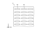
- FIG. 2 is a diagram showing an example of a schematic configuration of the modulation section 5.
- the modulation unit 5 is schematically shown when viewed in the negative Z-axis direction. Note that in the figure, a white arrow extending in the X-axis direction schematically indicates X-polarized light. A white arrow extending in the Y-axis direction schematically indicates Y-polarized light.
- the modulator 5 has, for example, a configuration similar to that of a modulation liquid crystal panel in which liquid crystal molecules are aligned in-plane, with the polarizing plate removed.
- the modulation section 5 includes a plurality of liquid crystal sections 51. Each liquid crystal section 51 corresponds to each part of the display element 2. Light from a corresponding portion of each portion of the display element 2 enters each of the plurality of liquid crystal portions 51 . In each liquid crystal section 51, one or more liquid crystal molecules 5m are arranged. Light from each part of the display element 2 passes through liquid crystal molecules 5m arranged in the corresponding liquid crystal section 51.
- Each liquid crystal section 51 is driven individually. For example, voltage application to each liquid crystal section 51 is individually controlled. Driving the liquid crystal section 51 includes changing the state of the liquid crystal molecules 5m arranged in the liquid crystal section 51. An example of the state of the liquid crystal molecules 5m is the orientation of the liquid crystal molecules 5m.
- the liquid crystal molecules 5m have an orientation of 45 degrees with respect to the X-axis and the Y-axis when no voltage is applied and they are not driven (default state). It is assumed that the applied phase difference is 1/2 wavelength.
- the Y-polarized light from the polarizing plate 4 enters the liquid crystal section 51, the Y-polarized light is converted into X-polarized light and output.
- the liquid crystal molecules 5m have an orientation of 90 degrees with respect to the X axis (0 degrees with respect to the Y axis) when a voltage is applied and the liquid crystal molecules 5m are driven (driving state).
- the Y-polarized light that has entered the liquid crystal section 51 is directly output as Y-polarized light.
- the modulation unit 5 individually polarizes the light that has passed through each liquid crystal unit 51, that is, the light from each part of the display element 2, into either X-polarized light or Y-polarized light. do.
- the selection of the X-polarized light and the Y-polarized light here changes the virtual image position (depth).
- the modulator 5 is configured to include a plurality of layers, each layer having a different phase amount and phase axis angle. You can.
- the illustrated lens L1 is an aspherical lens, and is provided between the modulation section 5 and the optical path section 6.
- Lens L1 may be designed such that the angle of incidence is larger (for example, 5 degrees or more) than the angle of exit. It is possible to ensure the amount of inward bending of the chief ray at the maximum angle of view, and it is possible to adjust the diopter while maintaining the image plane.
- the light that has passed through the lens L1 enters the optical path section 6.
- the optical path section 6 is a section through which the light polarization-modulated by the modulation section 5 (in this example, the light from the lens L1) passes.
- the optical path section 6 is configured such that the optical path length of the light passing through the optical path section 6 differs depending on the polarization direction when the light is incident on the optical path section 6.
- the optical path section 6 is configured such that the refractive index of light passing through the optical path section 6 differs depending on the polarization direction of the light. This will be explained with reference to FIG.
- FIG. 3 is a diagram showing an example of a schematic configuration of the optical path section 6.
- the optical path portion 6 when viewed in the negative Z-axis direction is schematically shown.
- the optical path section 6 includes a plurality of liquid crystal molecules 6m.
- the plurality of liquid crystal molecules 6m are arranged so that the refractive index of the light passing therethrough varies depending on the polarization direction of the light.
- the plurality of liquid crystal molecules 6m are, for example, polymer liquid crystals, and are all arranged in the same direction.
- the plurality of liquid crystal molecules 6m have an orientation of 0 degrees with respect to the X axis (orientation of 90 degrees with respect to the Y axis).
- the optical path section 6 gives mutually different refractive indexes to the X-polarized light and the Y-polarized light.
- the refractive index of Y-polarized light is higher than the refractive index of X-polarized light.
- the refractive index of X-polarized light is 1.52
- the refractive index of Y-polarized light is 1.77.
- the refractive index difference is 0.25.
- the optical path length of the X-polarized light and the optical path length of the Y-polarized light passing through the optical path section 6 are different from each other.
- the optical path length of Y-polarized light is longer than the optical path length of X-polarized light. That is, by combining the polarization modulation by the modulation section 5 and the optical path section 6, the optical path length of the light from each part of the display element 2 can be changed.
- the optical path length of the light passing through the optical path unit 6 corresponds to the focus adjustment interval of the optical system 3, and as a result, changes the virtual image position (Diopter). For example, a virtual image formed by light with a short optical path length is observed to be located in the front, and a virtual image formed by light with a long optical path length is observed to be located in the back. The virtual image position can be adjusted.
- the difference between the virtual image position in the case of X-polarized light and the virtual image position in the case of Y-polarized light is due to the thickness (length in the Z-axis direction) of the optical path section 6.
- the thickness of the optical path section 6 is designed so that a desired difference between the two virtual image positions can be obtained. For example, as mentioned above, if the refractive index difference is 0.25 and the optical path length is 0.664 m (air length) to make the difference between the two virtual image positions 0.6 D (D is the diopter value), the optical path The thickness of the portion 6 is designed to be 2.655 mm (0.644/0.25).
- the polarizing plate 7 is disposed on the opposite side of the modulating section 5 with the optical path section 6 (in this example, the optical path section 6 and the lens L1) in between, and converts the light from the optical path section 6 into predetermined polarized light. rectify. Thereby, the final polarized light of the light after passing through the optical path section 6 can be unified.
- a configuration including a lens L1, a lens L2, and a lens L3 can be adopted.
- the polarizing plate 7 rectifies the light from the optical path section 6 so that the light from the optical path section 6 becomes 45-degree polarized light.
- the polarizing plate 7 is arranged to have an azimuth angle of, for example, 45 degrees.
- Lens L2 and lens L3 are aspherical lenses designed to form an image of the light from polarizing plate 7, and are provided in order on the opposite side of modulation unit 5 with optical path unit 6 and polarizing plate 7 in between.
- Lens L2 may be configured with positive refractive power (focal length >0) and lens L3 may be configured with negative refractive power (focal length ⁇ 0).
- the refractive index of the lens L3 at the d-line may be greater than the refractive index of the lens L2.
- the Abbe number of the lens L3 at the d-line may be smaller than the Abbe number of the lens L2. Lateral chromatic aberration can be effectively corrected.
- the flat plate B is a transparent flat plate that transmits the light from the lens L3.
- the surface of the flat plate B (for example, the surface on the negative side of the Z-axis) may be a transflective surface that reflects part of the incident light and allows part of it to pass through. For example, a half mirror may be used.
- the illustrated optical system 3 has a triple-pass configuration in which light from the display element 2 passes through three lenses: a lens L1, a lens L2, and a lens L3. With such a configuration, the optical system 3 can be made thinner and smaller.
- FIG. 4 is a diagram showing an example of the polarization direction of light in the optical system 3.
- the polarization directions of the light after passing through the polarizing plate 4, the modulating section 5, and the polarizing plate 7 are schematically indicated by white arrows. All of the light that has passed through the polarizing plate 4 is Y-polarized light.
- the light that has passed through the modulator 5 is either X-polarized light or Y-polarized light.
- the light that has passed through the polarizing plate 7 is 45 degree polarized light.
- the optical path length of light from each part of the display element 2 can be changed by the combination of the polarization modulation by the modulation section 5 and the optical path section 6. This makes it possible to adjust the virtual image position, making it possible to deal with convergence adjustment contradictions. Eye sensing is not essential, and since a focusing mechanism is not required, the camera can be made smaller and lighter. Therefore, it is possible to suppress the increase in size of the device while dealing with the congestion adjustment contradiction.
- this method has the advantage of being easily applicable to images in which images in the foreground and images in the background are mixed in a complex manner.
- this method in a method of using a plurality of panels for the VR optical system, it is necessary to position the panels quite close to each other in the Z-axis direction, and it is also difficult to correct aberrations.
- a beam splitter When combining two images using a beam splitter, there is no back focus at high resolution and a wide viewing angle, so it cannot be incorporated.
- the influence of aberrations caused by the optical path section 6 is slight.
- the contrast characteristics with respect to the spatial frequencies of the portions of the video that are adjusted to different virtual image positions are all within a range that poses no problem for practical use.
- FIG. 5 is a diagram illustrating an example of a schematic configuration of a display device 1 according to a modification.
- the optical system 3 of the display device 1 includes an optical path section 8 instead of the optical path section 6 (FIG. 1) described above.
- the optical path section 8 is also configured such that the optical path length of the light passing through the optical path section 8 varies depending on the polarization direction when the light is incident on the optical path section 8.
- the specific configuration of the optical path section 8 is different from the configuration of the optical path section 6.
- the optical path section 8 will be explained with reference also to FIGS. 6 and 7.
- FIG. 6 is a diagram showing an example of a schematic configuration of the optical path section 8.
- the optical path section 8 includes a wavelength plate 81, a half mirror 81a, a wavelength plate 82, and a reflective polarizing plate 82a.
- the wavelength plate 81, the half mirror 81a, the wavelength plate 82, and the reflective polarizing plate 82a are arranged in this order.
- the wavelength plate 81 and the half mirror 81a are arranged so as to be stuck to each other.
- the half mirror 81a and the wave plate 82 are arranged at intervals.
- the wavelength plate 82 and the reflective polarizing plate 82a are attached to each other.
- the traveling direction of light passing through the optical path section 8 is schematically indicated by a black arrow.
- the wavelength plate 81 is a first wavelength plate that converts the linearly polarized light from the modulator 5 into circularly polarized light according to the polarization direction of the linearly polarized light.
- the wavelength plate 81 is, for example, a quarter wavelength plate (QWP), and converts the X-polarized light or the Y-polarized light that has passed through the wavelength plate 81 into circularly polarized light.
- QWP quarter wavelength plate
- the direction of rotation of the circularly polarized light obtained when the X-polarized light passes through the wave plate 81 and the direction of rotation of the circularly polarized light obtained when the Y-polarized light passes through the wave plate 81 are opposite to each other.
- the half mirror 81a is arranged between the wavelength plate 81 and the wavelength plate 82, and reflects a part of the incident light and allows the part to pass through. A portion of the circularly polarized light from the wave plate 81 passes through the half mirror 81a and heads toward the wave plate 82.
- the wavelength plate 82 converts the circularly polarized light from the wavelength plate 81, more specifically, the circularly polarized light from the half mirror 81a in this example, into linearly polarized light according to the rotation direction of the circularly polarized light. It is a board.
- the wavelength plate 82 is, for example, a quarter-wave plate, and converts the circularly polarized light from the wavelength plate 81 into X-polarized light or Y-polarized light.
- the reflective polarizing plate 82a is placed on the opposite side of the wavelength plate 81 (in this example, the wavelength plate 81 and the half mirror 81a) with the wavelength plate 82 in between.
- the reflective polarizing plate 82a allows predetermined linearly polarized light to pass therethrough and reflects other linearly polarized light.
- the reflective polarizer 82a reflects Y-polarized light while passing X-polarized light. As a result, only X-polarized light is emitted from the optical path section 8.
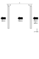
- FIG. 7 is a diagram showing an example of the optical path length of the optical path section 8.
- the wave plate 81 and the half mirror 81a are illustrated separated from each other.
- the rotation direction of circularly polarized light is schematically illustrated by a circular arrow.
- the optical path when X-polarized light enters the optical path section 8 is schematically shown by a black arrow.
- the X-polarized light passes through the wave plate 81 and becomes circularly polarized light. A portion of this circularly polarized light passes through the half mirror 81a, passes through the wavelength plate 83, and becomes X-polarized light. This X-polarized light passes through the reflective polarizing plate 84 and is emitted.
- the light passing through the optical path section 8 passes between the half mirror 81a and the reflective polarizing plate 82a only once (one pass).
- the optical path when Y-polarized light enters the optical path section 8 is schematically shown by a black arrow.
- the Y polarized light passes through the wave plate 81 and becomes circularly polarized light. A portion of this circularly polarized light passes through the half mirror 81a and further passes through the wavelength plate 83 to become Y-polarized light. This Y-polarized light is reflected by the reflective polarizing plate 84, passes through the wavelength plate 83, and becomes circularly polarized light.
- a portion of this circularly polarized light is reflected by the half mirror 81a, passes through the wavelength plate 83, and becomes X-polarized light.
- This X-polarized light passes through the reflective polarizing plate 84 and is emitted.
- the light passing through the optical path section 8 passes between the half mirror 81a and the reflective polarizing plate 82a three times (three passes).
- the optical path length of the Y-polarized light is longer than the optical path length of the X-polarized light when it enters the optical path unit 8. That is, by combining the polarization modulation by the modulation section 5 and the optical path section 8, the optical path length of the light from each part of the display element 2 can be changed. It is also possible to adjust the virtual image position in this way. For example, if the optical path length to make the difference between the two virtual image positions 0.6D is 0.664 m (air length), the thickness of the optical path section 8 is designed to be 0.322 mm (0.644/2). Ru. It is most desirable for the half mirror 81a to have a transmission efficiency of around 38% and a reflection efficiency of around 62%. This is because the efficiency of the single-pass optical path, 38%, and the efficiency of the triple-pass, 62% ⁇ 62% ⁇ 38%, are approximately the same.
- FIG. 8 is a diagram illustrating an example of a schematic configuration of a display device 1 according to a modification.
- the illustrated display device 1 includes two sets of a polarizing plate 4 , a modulating section 5 , an optical path section 6 , and a polarizing plate 7 .
- the polarizing plate 4, modulating section 5, optical path section 6, and polarizing plate 7 related to the second set are referred to as polarizing plate 4-2, modulating section 5-2, optical path section 6-2, and polarizing plate 7-2, and are illustrated in the figure. do.
- a polarizing plate 4-2, a modulating section 5-2, an optical path section 6-2, and a polarizing plate 7-2 are arranged in this order between the polarizing plate 7 and the lens L2.
- the polarizing plate 4-2, the modulating section 5-2, the optical path section 6-2, and the polarizing plate 7-2 may have the same configuration as the polarizing plate 4, the modulating section 5, the optical path section 6, and the polarizing plate 7.
- the thickness of the optical path section 6-2 may be the same as or different from the thickness of the optical path section 6-1.
- the light to be polarized by the modulator 5-2 is the light from each part of the display element 2, and the light that has passed through the optical path section 6 (in this example, the light that has also passed through the polarizing plate 7 and the polarizing plate 4-2). It is.
- the light passing through the optical path section 6-2 is polarization-modulated light by the modulation section 5-2.
- the combination of the polarization modulation by the modulation unit 5 and the optical path unit 6 can provide two different virtual image positions. Two different virtual image positions can also be provided by the combination of the polarization modulation by the modulation section 5-2 and the optical path section 6-2. These combinations can provide three or more, up to four, different virtual image positions. This will be explained with reference to FIG.
- FIG. 9 is a diagram showing an example of polarization modulation by the modulation section 5 and the modulation section 5-2.
- FIG. 9A shows an example of polarization modulation by the modulation section 5.
- FIG. 9B shows an example of polarization modulation by the modulation section 5-2. Note that the liquid crystal and liquid crystal molecules of the modulation section 5-2 are illustrated as a liquid crystal section 51-2 and a liquid crystal molecule 5m-2.
- liquid crystal sections 51 of interest are marked with a diamond mark and a star mark.
- a diamond mark and a star mark are attached to two of the plurality of liquid crystal parts 51-2.
- Liquid crystal section 51 and liquid crystal section 51-2 with the same mark correspond to the same part of display element 2.
- the liquid crystal unit 51 marked with a star mark is driven, and the liquid crystal molecules 5m are aligned at 90 degrees with respect to the X axis (0 degrees with respect to the Y axis). ).
- the light that has passed through the liquid crystal section 51 passes through the optical path section 6 as Y-polarized light.
- the light that has passed through the other liquid crystal section 51 passes through the optical path section 6 as X-polarized light.
- the liquid crystal section 51-2 marked with a diamond mark and the liquid crystal section 51-2 marked with a star mark are driven, and the liquid crystal molecules 5m has an orientation of 90 degrees with respect to the X axis (0 degrees with respect to the Y axis).
- the light that has passed through these liquid crystal sections 51-2 passes through the optical path section 6-2 as Y-polarized light.
- the light that has passed through the other liquid crystal section 51-2 passes through the optical path section 6-2 as X-polarized light.
- the optical path of the light passing through the liquid crystal section 51 and the liquid crystal section 51-2 marked with star marks is the longest.
- the optical path of the light passing through the liquid crystal section 51 and the liquid crystal section 51-2 with the diamond marks becomes longer.
- the optical path of the light that has passed through the other liquid crystal sections 51 and 51-2 is the shortest.
- the refractive index difference in the optical path section 6 is 0.25 and the thickness of the optical path section 6 is 0.8 mm
- the refractive index difference in the optical path section 6-2 is 0.25
- the thickness of the optical path section 6-2 is 0.8 mm.
- the difference between the two virtual image positions obtained by the optical path section 6-2 is 0.6D.
- the total of the optical path section 6 and the optical path section 6-2 is 0.8D.
- the light that has passed through the liquid crystal section 51 and the liquid crystal section 51-2 marked with star marks is Y-polarized light both when it enters the optical path section 6 and when it enters the optical path section 6-2, and the optical path length is the longest. become longer.
- a virtual image position of 0.5D is given.
- the light that has passed through the liquid crystal section 51 and the liquid crystal section 51-2 with diamond marks is X-polarized light when it enters the optical path section 6, and Y-polarized light when it enters the optical path section 6-2. It is light.
- a virtual image position of 0.7D is given.
- the light that has passed through the other liquid crystal sections 51 and 51-2 is X-polarized light both when it is incident on the optical path section 6 and when it is incident on the optical path section 6-2, and the optical path length is the shortest.
- a 1.3D virtual image position is given.
- FIG. 10 is a diagram showing an example of the polarization direction of light in the optical system 3.
- the polarization direction of the light after passing through each of the polarizing plate 4, the modulating section 5, the polarizing plate 7, the polarizing plate 4-2, the modulating section 5-2, and the polarizing plate 7-2 is as follows. Schematically indicated by a white arrow. All of the light that has passed through the polarizing plate 4 is Y-polarized light. The light that has passed through the modulator 5 is either X-polarized light or Y-polarized light. The light that has passed through the polarizing plate 7 is 45 degree polarized light. All of the light that has passed through the polarizing plate 4-2 is Y-polarized light. The light that has passed through the modulator 5-2 is either X-polarized light or Y-polarized light. The light that has passed through the polarizing plate 7-2 is 45 degree polarized light.
- polarization modulation may be performed such that the modulation unit 5 converts the light into Y-polarized light and the modulation unit 5-2 converts it into X-polarized light. Light so polarized may provide yet another virtual image position. As a result, up to four different virtual image positions can be provided (eg 4 focal points VR).
- a wavelength plate may be stacked on the modulation section 5 to achieve a wide wavelength band. This will be explained with reference to FIG.
- FIG. 11 is a diagram showing an example of a schematic configuration of the modulation section 5.
- a wavelength plate 5a is provided for the modulation section 5.
- a wave plate 5a is stacked on the surface of the modulation section 5 on the Z-axis positive direction side.
- the wavelength plate 5a is, for example, a 1/2 wavelength plate with an azimuth axis of 114.5 degrees. It is possible to improve the wavelength characteristics of the modulation section 5 itself, that is, the liquid crystal section 51 itself in which the liquid crystal molecules 5m are arranged. For example, equivalent modulation can be performed over a wide wavelength band such as the RGB band. It becomes possible to improve RGB efficiency and crosstalk.
- the plurality of polarized lights obtained by polarization modulation by the modulator 5 may include polarized lights polarized in a direction between the X-axis direction and the Y-axis direction. This will be explained with reference to FIG.
- FIG. 12 is a diagram showing an example of polarization modulation by the modulation section 5.
- An asterisk is attached to the liquid crystal section 51 in the driven state.
- the liquid crystal molecules 5m have an orientation of 67.5 degrees with respect to the X axis (22.5 degrees with respect to the Y axis).
- the Y-polarized light incident on the liquid crystal section 51 is polarized and modulated to become 45-degree polarized light.
- this light passes through the optical path section 6, since the optical path length in the optical path section 6 is different between the X-polarized light and the Y-polarized light, it behaves as if the optical path length in both cases exists.
- both a 0.5D virtual image position and a 1.1D virtual image position are provided.
- the virtual image positions are superimposed, but due to a psychological effect, the user can view the image as if there was a virtual image position of 0.8D between them.
- the optical system 3 has a triple-pass system configuration including the lens L1, the lens L2, and the lens L3 has been described as an example.
- the triple-pass type configuration is not essential, and various other configurations may be adopted. Examples of other configurations include Fresnel systems, two-panel configurations, and the like.
- the D value is not limited to the values described above, and may be designed to be any various values.
- 0.5D was used as a reference, but design may be performed using 0D as a reference.
- the air portions at both ends of the optical path portion 6 (or the optical path portion 6 and the polarizing plate 7) in the Z-axis direction are portions that can change the virtual image position, so the diopter can be adjusted by adjusting the length of this portion. may be performed. This diopter adjustment may simply be used to correct visual acuity such as nearsightedness and farsightedness.
- the length of the air portions at both ends of the optical path section 6 may be roughly adjusted, and then the virtual image position may be adjusted by the combination of the modulation section 5 and the optical path section 6 as described above. For example, it is possible to further expand the virtual image correction range while reducing the sense of discomfort in close-up views mixed in with distant views.
- the length of the air portions at both ends of the optical path section 6 and the virtual image position (Diopter) do not have a simple proportional relationship, they may be designed with reference to a data table or calculation formula prepared in advance. The same may be applied to the case where the polarization direction by the modulator 5 is determined.
- the portion of the video that the user is viewing may be specified (identified, etc.) by eye sensing. This will be explained with reference to FIG.
- FIG. 13 is a diagram illustrating an example of a schematic configuration of a display device 1 according to a modification.
- FIG. 13A shows a schematic configuration of the display device 1. Note that the configurations of the display element 2 and the optical system 3 are illustrated in a simplified manner.
- the display device 1 further includes a projector 9 and a camera 10 for eye sensing.
- the projector 9 and the camera 10 are arranged at a position where the optical system 3 does not interfere with the light from the display element 2 on which the image is formed.
- the projector 9 emits light toward the user's U eyes, for example.
- An example of light is infrared light.
- the camera 10 detects the light reflected by the user's U pupil and images the eye E based on the light reflected by the user's U pupil.
- FIG. 13B shows an example of the imaged eye E of the user.
- an object point P on the eye E on the pupil
- a Purkinje image is acquired, and thereby the location in the video that the user is viewing is specified.
- the virtual image position may be adjusted based on the results of such eye sensing.
- the interval (pitch) between adjacent liquid crystal sections 51 in the modulation section 5 may be coarser than the interval (for example, pixel pitch) between each part of the display element 2.
- the display element 2 may have a 4K resolution (3840x2160), and the resolution of the modulator 5 may be HD (1280x720), FHD (1920x1080), or the like. This is because while the display element 2 has a direct effect on image quality, the modulation section 5 only changes the virtual image position, and there is no problem even if the degree of fineness is relatively small. For example, even if the aperture ratio of the transmissive liquid crystal of the modulation section 5 is not so high, the low resolution can compensate for this point. The image focus of the modulating section 5 is shifted from that of the display element 2, and in this sense as well, it can be said that there is little need for the modulating section 5 to have high resolution.
- birefringent crystals having different dispersions in XY may be arranged instead of a laminated layer of liquid crystal polymers. Examples include CaCO 3 crystal (calcite), ⁇ -BaB2O4, and the like.
- the optical path section 6 described below may be read as the optical path section 8 as appropriate within the scope of consistency.
- One of the techniques disclosed is the optical system 3.
- the optical system 3 forms an image of the light from the display element 2.
- the optical system 3 includes a modulation section 5 and an optical path section 6.
- the modulator 5 individually polarizes the light from each part of the display element 2 so that the light from each part of the display element 2 becomes one of a plurality of polarized lights having different polarization directions. Modulate.
- the optical path section 6 is a section through which the light polarization-modulated by the modulation section 5 passes.
- the optical path section 6 is configured such that the optical path length of the light passing through the optical path section 6 differs depending on the polarization direction when the light is incident on the optical path section 6.
- the optical path length of the light from each part of the display element 2 can be changed by the combination of the polarization modulation by the modulation section 5 and the optical path section 6. This makes it possible to adjust the virtual image position, making it possible to deal with convergence adjustment contradictions. For example, there is no need to move the display element 2 as in Patent Document 1, and it is possible to suppress the increase in size of the device. It is possible to suppress the increase in size of the device while dealing with congestion adjustment contradictions.
- the modulation section 5 includes a plurality of liquid crystal sections 51 each having a liquid crystal molecule 5m arranged thereon and driven individually. Light from a corresponding part of each part is incident, and driving the liquid crystal part 51 may include changing the state of the liquid crystal molecules 5m arranged in the liquid crystal part 51 (for example, the direction of the liquid crystal molecules 5m). .
- the modulation section 5 having such a configuration can individually polarize the light from each part of the display element 2.
- the optical path section 6 may be configured such that the refractive index of light passing through the optical path section 6 differs depending on the polarization direction of the light.
- the optical path section 6 may include a plurality of liquid crystal molecules 6m arranged in the same direction.
- the optical path length of the light passing through the optical path section 6 can be varied depending on the polarization direction at the time of incidence.
- the optical path section 8 includes a wavelength plate 81 (wave plate 81) that converts the linearly polarized light from the modulator 5 into circularly polarized light according to the polarization direction of the linearly polarized light. 1), a wavelength plate 82 (second wavelength plate) that converts the circularly polarized light from the wavelength plate 81 into linearly polarized light according to the rotation direction of the circularly polarized light, and the wavelength plate 81 and the wavelength plate.
- a wavelength plate 81 wave plate 81
- second wavelength plate that converts the circularly polarized light from the wavelength plate 81 into linearly polarized light according to the rotation direction of the circularly polarized light
- a half mirror 81a disposed between the half mirror 81a and a reflective polarizing plate 82a disposed on the opposite side of the wavelength plate 81 with the wavelength plate 82 in between, which passes a predetermined linearly polarized light and reflects other linearly polarized light; and may include.
- the optical path length of the light passing through the optical path section 8 can be varied depending on the polarization direction at the time of incidence.
- the optical system 3 is disposed between the display element 2 and the modulator 5, and allows only predetermined polarized light to pass among the light from the display element 2.
- a polarizing plate 4 may be provided. Even when the display element 2 emits light containing polarized light in various directions, the polarized light that enters the modulation section 5 can be limited.
- the display element 2 may include an OLED (Organic Light Emitting Diode).
- the optical system 3 includes a polarizing plate that is disposed on the opposite side of the modulation section 5 with the optical path section 6 in between, and that rectifies the light from the optical path section 6 into predetermined polarized light. 7 may be provided. Thereby, the final polarized light after passing through the optical path section 6 can be unified.
- the optical system 3 includes a plurality of lenses for imaging the light from the display element 2, and the plurality of lenses include a lens L1 provided between the modulation section 5 and the optical path section 6, and a lens L1 provided between the modulation section 5 and the optical path section 6 (or the optical path section 6). It may include a lens L2 and a lens L3 that are provided in this order on the opposite side of the modulation section 5 with the optical path section 6 and polarizing plate 7 interposed therebetween. For example, such a triple pass configuration can be adopted.
- the optical system 3 may include the modulation section 5-2 and the optical path section 6-2.
- the modulator 5-2 modulates the display so that the light from each part of the display element 2 that passes through the optical path section 6 becomes one of a plurality of polarized lights having different polarization directions.
- This is a second modulation section that individually polarizes and modulates the light from each part of the element 2 that has passed through the optical path section 6.
- the optical path section 6-2 is a second optical path section through which the light polarization-modulated by the modulation section 5-2 passes.
- the optical path section 6-2 is configured such that the optical path length of the light passing through the optical path section 6-2 differs depending on the polarization direction of the light when it enters the optical path section 6-2. Thereby, more different virtual image positions can be provided than in the case where only one modulation section 5 and one optical path section 6 are provided.
- the modulation section 5 may have a wave plate 5a laminated thereon. This makes it possible to widen the wavelength band.
- the display element 2 extends in the XY plane direction, and the plurality of polarized lights obtained by polarization modulation of the modulation unit 5 are polarized in the X-axis direction. It may include X-polarized light and Y-polarized light polarized in the Y-axis direction. For example, by using such polarized light, the optical path length of light from each part of the display element 2 can be changed to provide different virtual image positions. As described with reference to FIG. 12 and the like, the plurality of polarized lights may include polarized lights polarized in a direction between the X-axis direction and the Y-axis direction. Thereby, different virtual image positions can be mixed to provide a virtual image position in a pseudo intermediate state.
- the display device 1 described with reference to FIGS. 1 to 7 and the like is also one of the disclosed technologies.
- the display device 1 includes a display element 2 and an optical system 3 that forms an image of light from the display element 2.
- the optical system 3 is as described above. With such a display device 1, as described above, it is possible to suppress the increase in size of the device while dealing with the convergence adjustment contradiction.
- the display device 1 may include the camera 10 for eye sensing. For example, it becomes possible to adjust the virtual image position based on the results of eye sensing.
- the present technology can also have the following configuration.
- An optical system that images light from a display element, a modulator that individually polarizes and modulates the light from each part of the display element so that the light from each part of the display element becomes one of a plurality of polarized lights having different polarization directions; , an optical path section through which the light polarization-modulated by the modulation section passes; Equipped with The optical path section is configured such that the optical path length of the light passing through the optical path section varies depending on the polarization direction when the light enters the optical path section.
- Optical system that images light from a display element, a modulator that individually polarizes and modulates the light from each part of the display element so that the light from each part of the display element becomes one of a plurality of polarized lights having different polarization directions; , an optical path section through which the light polarization-modulated by the modulation section passes; Equipped with The optical path section is configured such that the optical path length of the light passing through the optical
- the modulation unit includes a plurality of liquid crystal units each having liquid crystal molecules arranged therein and driven individually; Light from a corresponding portion of each portion of the display element is incident on each of the plurality of liquid crystal portions,
- the driving of the liquid crystal section includes changing the state of the liquid crystal molecules arranged in the liquid crystal section.
- the state of the liquid crystal molecules includes the orientation of the liquid crystal molecules, The optical system described in (2).
- the optical path section is configured such that the refractive index of light passing through the optical path section differs depending on the polarization direction of the light.
- the optical system according to any one of (1) to (3).
- the optical path section includes a plurality of liquid crystal molecules arranged in the same direction. The optical system described in (4).
- the optical path section is a first wavelength plate that converts the linearly polarized light from the modulation section into circularly polarized light according to the polarization direction of the linearly polarized light; a second wavelength plate that converts the circularly polarized light from the first wavelength plate into linearly polarized light according to the rotation direction of the circularly polarized light; a half mirror disposed between the first wave plate and the second wave plate; a reflective polarizing plate that is disposed on the opposite side of the first wavelength plate with the second wavelength plate in between and passes a predetermined linearly polarized light and reflects other linearly polarized light; including, The optical system according to any one of (1) to (3).
- the optical system according to any one of (1) to (6).
- the display element includes an OLED (Organic Light Emitting Diode).
- the optical system according to any one of (1) to (7). (9) comprising a polarizing plate disposed on the opposite side of the modulation section across the optical path section and rectifying the light from the optical path section into predetermined polarized light;
- the plurality of lenses are a lens provided between the modulation section and the optical path section; two lenses provided in order on the opposite side of the modulation section across the optical path section; including, The optical system according to any one of (1) to (9).
- the light from each part of the display element is configured such that the light from each part of the display element that passes through the optical path becomes one of a plurality of polarized lights having different polarization directions.
- a second modulation section that individually polarizes and modulates the light that has passed through the optical path section; a second optical path section through which the light polarization-modulated by the second modulation section passes; Equipped with The second optical path section is configured such that the optical path length of the light passing through the optical path section varies depending on the polarization direction when the light enters the second optical path section.
- the display element extends in the XY plane direction,
- the plurality of polarized lights obtained by polarization modulation of the modulation unit include X-polarized light polarized in the X-axis direction and Y-polarized light polarized in the Y-axis direction.
- the display element extends in the XY plane direction,
- the plurality of polarized lights obtained by polarization modulation of the modulation unit include polarized lights polarized in a direction between an X-axis direction and a Y-axis direction.
- the optical system according to any one of (1) to (13).
- a display element an optical system that images light from the display element; Equipped with The optical system is a modulator that individually polarizes and modulates the light from each part of the display element so that the light from each part of the display element becomes one of a plurality of polarized lights having different polarization directions; , an optical path section through which the light polarization-modulated by the modulation section passes; including; The optical path section is configured such that the optical path length of the light passing through the optical path section varies depending on the polarization direction when the light enters the optical path section.
- Display device (16) Equipped with a camera for eye sensing, The display device according to (15).
Landscapes
- Physics & Mathematics (AREA)
- General Physics & Mathematics (AREA)
- Optics & Photonics (AREA)
- Nonlinear Science (AREA)
- Chemical & Material Sciences (AREA)
- Crystallography & Structural Chemistry (AREA)
Abstract
Un aspect de la présente divulgation supprime l'augmentation de taille d'un dispositif tout en traitant un conflit d'accommodation de vergence. Un système optique (3) pour former une image de lumière à partir d'un élément d'affichage (2) comprend : une partie de modulation (5) qui polarise et module individuellement la lumière provenant de chaque partie de l'élément d'affichage de telle sorte que la lumière provenant de chaque partie de l'élément d'affichage devient tout faisceau de lumière polarisée parmi une pluralité de faisceaux de lumière polarisée ayant différentes directions de polarisation ; et une partie de trajet optique (6) à travers laquelle passe la lumière polarisée et modulée par la partie de modulation. La partie de trajet optique est configurée de telle sorte que la longueur de trajet optique de la lumière traversant la partie de trajet optique diffère selon la direction de polarisation lorsque la lumière est incidente sur la partie de trajet optique.
Applications Claiming Priority (2)
| Application Number | Priority Date | Filing Date | Title |
|---|---|---|---|
| JP2022-113888 | 2022-07-15 | ||
| JP2022113888 | 2022-07-15 |
Publications (1)
| Publication Number | Publication Date |
|---|---|
| WO2024014202A1 true WO2024014202A1 (fr) | 2024-01-18 |
Family
ID=89536530
Family Applications (1)
| Application Number | Title | Priority Date | Filing Date |
|---|---|---|---|
| PCT/JP2023/021463 WO2024014202A1 (fr) | 2022-07-15 | 2023-06-09 | Système optique et dispositif d'affichage |
Country Status (1)
| Country | Link |
|---|---|
| WO (1) | WO2024014202A1 (fr) |
Citations (5)
| Publication number | Priority date | Publication date | Assignee | Title |
|---|---|---|---|---|
| JP2002156603A (ja) * | 2000-11-16 | 2002-05-31 | Nippon Telegr & Teleph Corp <Ntt> | 三次元表示方法および装置 |
| WO2015190157A1 (fr) * | 2014-06-13 | 2015-12-17 | 三菱電機株式会社 | Dispositif d'affichage d'image virtuelle |
| US20180048881A1 (en) * | 2016-08-12 | 2018-02-15 | Avegant Corp. | Near-eye display system including a modulation stack |
| US20200249480A1 (en) * | 2019-02-06 | 2020-08-06 | Google Llc | Multi-focal catadioptric head mounted display with lc switch |
| WO2022038777A1 (fr) * | 2020-08-21 | 2022-02-24 | コピン コーポレーション | Dispositif d'affichage vidéo à champ large |
-
2023
- 2023-06-09 WO PCT/JP2023/021463 patent/WO2024014202A1/fr unknown
Patent Citations (5)
| Publication number | Priority date | Publication date | Assignee | Title |
|---|---|---|---|---|
| JP2002156603A (ja) * | 2000-11-16 | 2002-05-31 | Nippon Telegr & Teleph Corp <Ntt> | 三次元表示方法および装置 |
| WO2015190157A1 (fr) * | 2014-06-13 | 2015-12-17 | 三菱電機株式会社 | Dispositif d'affichage d'image virtuelle |
| US20180048881A1 (en) * | 2016-08-12 | 2018-02-15 | Avegant Corp. | Near-eye display system including a modulation stack |
| US20200249480A1 (en) * | 2019-02-06 | 2020-08-06 | Google Llc | Multi-focal catadioptric head mounted display with lc switch |
| WO2022038777A1 (fr) * | 2020-08-21 | 2022-02-24 | コピン コーポレーション | Dispositif d'affichage vidéo à champ large |
Similar Documents
| Publication | Publication Date | Title |
|---|---|---|
| CN110941088B (zh) | 透视型显示装置 | |
| CN215982382U (zh) | 用于将图像显示到观察者的眼睛中的显示器 | |
| US7675684B1 (en) | Compact optical system | |
| CN112654902B (zh) | 具有空间变化相移器光学器件的头戴式显示器(hmd) | |
| US6989935B2 (en) | Optical arrangements for head mounted displays | |
| WO2020036619A1 (fr) | Amélioration de transmission pour lunettes à ra/rv basées sur une lentille plate | |
| US20200033614A1 (en) | Display apparatus and on-vehicle head-up display system | |
| US11619816B2 (en) | Head-mounted display | |
| EP4184226A2 (fr) | Polariseur réfléchissant à cristaux liquides et ensemble lentille à galette doté de celui-ci | |
| US20240061248A1 (en) | Anamorphic directional illumination device | |
| US11640060B2 (en) | Head-mounted display | |
| US20230418068A1 (en) | Anamorphic directional illumination device | |
| US11215743B2 (en) | Achromatic optical device based on birefringent materials having positive and negative birefringence dispersions | |
| WO2024014202A1 (fr) | Système optique et dispositif d'affichage | |
| US20220367839A1 (en) | Color conversion display with polarized emission enhancement | |
| US20220365266A1 (en) | Apochromatic liquid crystal polarization hologram device | |
| US11869560B2 (en) | Object tracking system including polarization selective optical element | |
| JP2011257645A (ja) | プロジェクター | |
| TW202246848A (zh) | 包含偏振選擇性的微透鏡陣列的顯示裝置 | |
| JPH07128614A (ja) | 画像表示装置 | |
| US20230418034A1 (en) | Anamorphic directional illumination device | |
| US20240118547A1 (en) | Optical Display System and Electronics Device | |
| JP7476073B2 (ja) | 表示装置 | |
| US11796881B2 (en) | Blue phase liquid crystal polarization hologram comprising liquid crystal molecules having a spatially varying in-plane orientation pattern and device including the same | |
| US12099190B2 (en) | Waveguide with polarization volume hologram grating |
Legal Events
| Date | Code | Title | Description |
|---|---|---|---|
| 121 | Ep: the epo has been informed by wipo that ep was designated in this application |
Ref document number: 23839378 Country of ref document: EP Kind code of ref document: A1 |