WO2024014202A1 - Optical system and display device - Google Patents
Optical system and display device Download PDFInfo
- Publication number
- WO2024014202A1 WO2024014202A1 PCT/JP2023/021463 JP2023021463W WO2024014202A1 WO 2024014202 A1 WO2024014202 A1 WO 2024014202A1 JP 2023021463 W JP2023021463 W JP 2023021463W WO 2024014202 A1 WO2024014202 A1 WO 2024014202A1
- Authority
- WO
- WIPO (PCT)
- Prior art keywords
- light
- optical path
- section
- path section
- display element
- Prior art date
Links
- 230000003287 optical effect Effects 0.000 title claims abstract description 305
- 230000010287 polarization Effects 0.000 claims abstract description 63
- 239000004973 liquid crystal related substance Substances 0.000 claims description 92
- 238000003384 imaging method Methods 0.000 claims description 4
- 238000010586 diagram Methods 0.000 description 26
- 230000004048 modification Effects 0.000 description 10
- 238000012986 modification Methods 0.000 description 10
- 238000000034 method Methods 0.000 description 8
- 230000004075 alteration Effects 0.000 description 6
- 229910003460 diamond Inorganic materials 0.000 description 5
- 239000010432 diamond Substances 0.000 description 5
- 230000007246 mechanism Effects 0.000 description 5
- 230000000694 effects Effects 0.000 description 4
- 238000005516 engineering process Methods 0.000 description 4
- 210000003128 head Anatomy 0.000 description 3
- 210000001747 pupil Anatomy 0.000 description 3
- 239000013078 crystal Substances 0.000 description 2
- 238000012545 processing Methods 0.000 description 2
- 229910021532 Calcite Inorganic materials 0.000 description 1
- 239000005264 High molar mass liquid crystal Substances 0.000 description 1
- 229920000106 Liquid crystal polymer Polymers 0.000 description 1
- 239000004977 Liquid-crystal polymers (LCPs) Substances 0.000 description 1
- 238000005452 bending Methods 0.000 description 1
- 230000008901 benefit Effects 0.000 description 1
- 230000005540 biological transmission Effects 0.000 description 1
- 230000008859 change Effects 0.000 description 1
- 238000013461 design Methods 0.000 description 1
- 239000006185 dispersion Substances 0.000 description 1
- 230000004305 hyperopia Effects 0.000 description 1
- 201000006318 hyperopia Diseases 0.000 description 1
- 230000007774 longterm Effects 0.000 description 1
- 201000003152 motion sickness Diseases 0.000 description 1
- 230000004379 myopia Effects 0.000 description 1
- 208000001491 myopia Diseases 0.000 description 1
- 230000001151 other effect Effects 0.000 description 1
- 230000004800 psychological effect Effects 0.000 description 1
- 230000004304 visual acuity Effects 0.000 description 1
Images


Classifications
-
- G—PHYSICS
- G02—OPTICS
- G02B—OPTICAL ELEMENTS, SYSTEMS OR APPARATUS
- G02B27/00—Optical systems or apparatus not provided for by any of the groups G02B1/00 - G02B26/00, G02B30/00
- G02B27/02—Viewing or reading apparatus
-
- G—PHYSICS
- G02—OPTICS
- G02B—OPTICAL ELEMENTS, SYSTEMS OR APPARATUS
- G02B27/00—Optical systems or apparatus not provided for by any of the groups G02B1/00 - G02B26/00, G02B30/00
- G02B27/28—Optical systems or apparatus not provided for by any of the groups G02B1/00 - G02B26/00, G02B30/00 for polarising
-
- G—PHYSICS
- G02—OPTICS
- G02B—OPTICAL ELEMENTS, SYSTEMS OR APPARATUS
- G02B30/00—Optical systems or apparatus for producing three-dimensional [3D] effects, e.g. stereoscopic images
- G02B30/50—Optical systems or apparatus for producing three-dimensional [3D] effects, e.g. stereoscopic images the image being built up from image elements distributed over a 3D volume, e.g. voxels
-
- G—PHYSICS
- G02—OPTICS
- G02B—OPTICAL ELEMENTS, SYSTEMS OR APPARATUS
- G02B5/00—Optical elements other than lenses
- G02B5/30—Polarising elements
-
- G—PHYSICS
- G02—OPTICS
- G02F—OPTICAL DEVICES OR ARRANGEMENTS FOR THE CONTROL OF LIGHT BY MODIFICATION OF THE OPTICAL PROPERTIES OF THE MEDIA OF THE ELEMENTS INVOLVED THEREIN; NON-LINEAR OPTICS; FREQUENCY-CHANGING OF LIGHT; OPTICAL LOGIC ELEMENTS; OPTICAL ANALOGUE/DIGITAL CONVERTERS
- G02F1/00—Devices or arrangements for the control of the intensity, colour, phase, polarisation or direction of light arriving from an independent light source, e.g. switching, gating or modulating; Non-linear optics
- G02F1/01—Devices or arrangements for the control of the intensity, colour, phase, polarisation or direction of light arriving from an independent light source, e.g. switching, gating or modulating; Non-linear optics for the control of the intensity, phase, polarisation or colour
- G02F1/13—Devices or arrangements for the control of the intensity, colour, phase, polarisation or direction of light arriving from an independent light source, e.g. switching, gating or modulating; Non-linear optics for the control of the intensity, phase, polarisation or colour based on liquid crystals, e.g. single liquid crystal display cells
Definitions
- the present disclosure relates to an optical system and a display device.
- Patent Document 1 discloses a technique for moving a liquid crystal display in the optical axis direction so that the convergence angle and the diopter match.
- a display element such as a liquid crystal display is moved in the optical axis direction, the device becomes larger.
- One aspect of the present disclosure suppresses device enlargement while addressing congestion adjustment contradictions.
- An optical system is an optical system that images light from a display element, and the light from each part of the display element is one of a plurality of polarized lights having different polarization directions.
- a modulation section that individually polarizes and modulates the light from each part of the display element so that it becomes polarized light, and an optical path section through which the light polarization-modulated by the modulation section passes.
- the optical path length of the light passing through the optical path section is configured to vary depending on the polarization direction when the light enters the optical path section.
- a display device includes a display element and an optical system that images light from the display element, and the optical system allows light from each part of the display element to be divided into multiple polarization directions.
- a modulator that individually polarize-modulates the light from each part of the display element so that the polarized light becomes one of the polarized lights, and an optical path section through which the light polarization-modulated by the modulator passes.
- the optical path section is configured such that the optical path length of light passing through the optical path section differs depending on the polarization direction of the light when it enters the optical path section.
- FIG. 1 is a diagram illustrating an example of a schematic configuration of a display device 1 according to an embodiment.
- 5 is a diagram showing an example of a schematic configuration of a modulation section 5.
- FIG. 3 is a diagram showing an example of a schematic configuration of an optical path section 6.
- FIG. 3 is a diagram showing an example of the polarization direction of light in the optical system 3.
- FIG. 3 is a diagram illustrating an example of a schematic configuration of a display device 1 according to a modification.
- 3 is a diagram showing an example of a schematic configuration of an optical path section 8.
- FIG. 5 is a diagram showing an example of the optical path length of the optical path section 8.
- FIG. FIG. 3 is a diagram illustrating an example of a schematic configuration of a display device 1 according to a modification.
- FIG. 5 is a diagram showing an example of polarization modulation by modulator 5 and modulator 5-2.
- FIG. 3 is a diagram showing an example of the polarization direction of light in the optical system 3.
- FIG. 5 is a diagram showing an example of a schematic configuration of a modulation section 5.
- FIG. 5 is a diagram showing an example of polarization modulation by a modulation section 5.
- FIG. 3 is a diagram illustrating an example of a schematic configuration of a display device 1 according to a modification.
- the disclosed technology it is possible to individually adjust the virtual image position corresponding to the light from each part (each position) of the display element, thereby making it possible to deal with convergence adjustment contradictions.
- Eye sensing is not essential, and since a focusing mechanism is not required, the device can be made smaller and lighter.
- the possibility of providing natural VR that is less likely to cause motion sickness and discomfort than ever before is also increasing.
- Embodiment FIG. 1 is a diagram showing an example of a schematic configuration of a display device 1 according to an embodiment.
- the display device 1 is, for example, an HMD that presents images such as VR, and is used by being worn on a user's head.
- the term "video” may be interpreted to include images, and the terms "video” and “image” may be interpreted as appropriate to the extent that there is no contradiction.
- the user's eye is referred to as user's eye E in the figure.
- the image presented by the display device 1 is observed by the eye E of the user.
- an XYZ coordinate system is shown.
- the display device 1 and the user's eye E are located in this order in the positive direction of the Z-axis.
- Each element of the display device 1 extends in the XY plane direction and has a thickness in the Z axis direction.
- 1A and 1B schematically show a side surface (or a cross section) of the display device 1 when viewed in the X-axis direction.
- FIG. 1B schematically shows several light paths.
- polarized light polarized in the X-axis direction is also referred to as X-polarized light.
- Polarized light polarized in the Y-axis direction is also referred to as Y-polarized light.
- Polarized light polarized in a direction of 45 degrees with respect to the X-axis direction and the Y-axis direction is also referred to as 45-degree polarized light.
- polarized light includes linearly polarized light and circularly polarized light, but unless otherwise specified, the term simply polarized light may be interpreted to mean linearly polarized light.
- the display device 1 includes a display element 2 and an optical system 3.
- the display element 2 and the optical system 3 are arranged in this order in the positive direction of the Z-axis.
- the display element 2 emits light that forms an image.
- the display element 2 is a display panel that has the XY plane direction as its surface direction and a display surface on the Z-axis negative direction side.
- the display element 2 includes, for example, an OLED (Organic Light Emitting Diode), an LC (Liquid Crystal), an LED (Light Emitting Diode), and the like.
- the display element 2 includes a plurality of parts, each of which is independently controlled to emit light. Typically, one portion of the display element 2 is one pixel of the display element 2.
- the optical system 3 forms an image of the light from the display element 2.
- the optical system 3 includes a polarizing plate 4, a modulation section 5, an optical path section 6, a polarizing plate 7, and other optical systems.
- Other optical systems include a lens L1, a lens L2, a lens L3, and a flat plate B.
- Polarizing plate 4, modulating section 5, lens L1, optical path section 6, polarizing plate 7, lens L2, lens L3, and flat plate B are arranged in this order in the positive direction of the Z-axis. Light from the display element 2 passes through these elements in order and is imaged so that the user observes a virtual image with the eye E.
- the polarizing plate 4 is arranged between the display element 2 and the modulation section 5.
- the polarizing plate 4 is, for example, a polarizer, a wire grid polarizer, or the like, and allows only predetermined polarized light out of the light from the display element 2 to pass through. Thereby, the polarized light that enters the modulation section 5 can be limited. For example, this is effective when the display element 2 includes an OLED that emits light containing various polarized lights. In the case where the display element 2 includes an LCD that emits only light containing a specific polarized light, the polarizing plate 4 may be omitted. In the following description, it is assumed that the predetermined polarized light that the polarizing plate 4 passes is Y-polarized light, unless otherwise specified.
- the modulator 5 polarizes and modulates the light from the display element 2 (in this example, the light from the polarizing plate 4).
- the modulator 5 individually polarizes the light from each part of the display element 2 so that the light from each part of the display element 2 becomes one of a plurality of polarized lights having different polarization directions. Modulate. Examples of the plurality of polarized lights include X-polarized light and Y-polarized light. Unless otherwise specified, the modulator 5 polarizes the light from each portion of the display element 2 individually into either X-polarized light or Y-polarized light. The modulator 5 will be explained with reference to FIG. 2 as well.
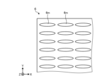
- FIG. 2 is a diagram showing an example of a schematic configuration of the modulation section 5.
- the modulation unit 5 is schematically shown when viewed in the negative Z-axis direction. Note that in the figure, a white arrow extending in the X-axis direction schematically indicates X-polarized light. A white arrow extending in the Y-axis direction schematically indicates Y-polarized light.
- the modulator 5 has, for example, a configuration similar to that of a modulation liquid crystal panel in which liquid crystal molecules are aligned in-plane, with the polarizing plate removed.
- the modulation section 5 includes a plurality of liquid crystal sections 51. Each liquid crystal section 51 corresponds to each part of the display element 2. Light from a corresponding portion of each portion of the display element 2 enters each of the plurality of liquid crystal portions 51 . In each liquid crystal section 51, one or more liquid crystal molecules 5m are arranged. Light from each part of the display element 2 passes through liquid crystal molecules 5m arranged in the corresponding liquid crystal section 51.
- Each liquid crystal section 51 is driven individually. For example, voltage application to each liquid crystal section 51 is individually controlled. Driving the liquid crystal section 51 includes changing the state of the liquid crystal molecules 5m arranged in the liquid crystal section 51. An example of the state of the liquid crystal molecules 5m is the orientation of the liquid crystal molecules 5m.
- the liquid crystal molecules 5m have an orientation of 45 degrees with respect to the X-axis and the Y-axis when no voltage is applied and they are not driven (default state). It is assumed that the applied phase difference is 1/2 wavelength.
- the Y-polarized light from the polarizing plate 4 enters the liquid crystal section 51, the Y-polarized light is converted into X-polarized light and output.
- the liquid crystal molecules 5m have an orientation of 90 degrees with respect to the X axis (0 degrees with respect to the Y axis) when a voltage is applied and the liquid crystal molecules 5m are driven (driving state).
- the Y-polarized light that has entered the liquid crystal section 51 is directly output as Y-polarized light.
- the modulation unit 5 individually polarizes the light that has passed through each liquid crystal unit 51, that is, the light from each part of the display element 2, into either X-polarized light or Y-polarized light. do.
- the selection of the X-polarized light and the Y-polarized light here changes the virtual image position (depth).
- the modulator 5 is configured to include a plurality of layers, each layer having a different phase amount and phase axis angle. You can.
- the illustrated lens L1 is an aspherical lens, and is provided between the modulation section 5 and the optical path section 6.
- Lens L1 may be designed such that the angle of incidence is larger (for example, 5 degrees or more) than the angle of exit. It is possible to ensure the amount of inward bending of the chief ray at the maximum angle of view, and it is possible to adjust the diopter while maintaining the image plane.
- the light that has passed through the lens L1 enters the optical path section 6.
- the optical path section 6 is a section through which the light polarization-modulated by the modulation section 5 (in this example, the light from the lens L1) passes.
- the optical path section 6 is configured such that the optical path length of the light passing through the optical path section 6 differs depending on the polarization direction when the light is incident on the optical path section 6.
- the optical path section 6 is configured such that the refractive index of light passing through the optical path section 6 differs depending on the polarization direction of the light. This will be explained with reference to FIG.
- FIG. 3 is a diagram showing an example of a schematic configuration of the optical path section 6.
- the optical path portion 6 when viewed in the negative Z-axis direction is schematically shown.
- the optical path section 6 includes a plurality of liquid crystal molecules 6m.
- the plurality of liquid crystal molecules 6m are arranged so that the refractive index of the light passing therethrough varies depending on the polarization direction of the light.
- the plurality of liquid crystal molecules 6m are, for example, polymer liquid crystals, and are all arranged in the same direction.
- the plurality of liquid crystal molecules 6m have an orientation of 0 degrees with respect to the X axis (orientation of 90 degrees with respect to the Y axis).
- the optical path section 6 gives mutually different refractive indexes to the X-polarized light and the Y-polarized light.
- the refractive index of Y-polarized light is higher than the refractive index of X-polarized light.
- the refractive index of X-polarized light is 1.52
- the refractive index of Y-polarized light is 1.77.
- the refractive index difference is 0.25.
- the optical path length of the X-polarized light and the optical path length of the Y-polarized light passing through the optical path section 6 are different from each other.
- the optical path length of Y-polarized light is longer than the optical path length of X-polarized light. That is, by combining the polarization modulation by the modulation section 5 and the optical path section 6, the optical path length of the light from each part of the display element 2 can be changed.
- the optical path length of the light passing through the optical path unit 6 corresponds to the focus adjustment interval of the optical system 3, and as a result, changes the virtual image position (Diopter). For example, a virtual image formed by light with a short optical path length is observed to be located in the front, and a virtual image formed by light with a long optical path length is observed to be located in the back. The virtual image position can be adjusted.
- the difference between the virtual image position in the case of X-polarized light and the virtual image position in the case of Y-polarized light is due to the thickness (length in the Z-axis direction) of the optical path section 6.
- the thickness of the optical path section 6 is designed so that a desired difference between the two virtual image positions can be obtained. For example, as mentioned above, if the refractive index difference is 0.25 and the optical path length is 0.664 m (air length) to make the difference between the two virtual image positions 0.6 D (D is the diopter value), the optical path The thickness of the portion 6 is designed to be 2.655 mm (0.644/0.25).
- the polarizing plate 7 is disposed on the opposite side of the modulating section 5 with the optical path section 6 (in this example, the optical path section 6 and the lens L1) in between, and converts the light from the optical path section 6 into predetermined polarized light. rectify. Thereby, the final polarized light of the light after passing through the optical path section 6 can be unified.
- a configuration including a lens L1, a lens L2, and a lens L3 can be adopted.
- the polarizing plate 7 rectifies the light from the optical path section 6 so that the light from the optical path section 6 becomes 45-degree polarized light.
- the polarizing plate 7 is arranged to have an azimuth angle of, for example, 45 degrees.
- Lens L2 and lens L3 are aspherical lenses designed to form an image of the light from polarizing plate 7, and are provided in order on the opposite side of modulation unit 5 with optical path unit 6 and polarizing plate 7 in between.
- Lens L2 may be configured with positive refractive power (focal length >0) and lens L3 may be configured with negative refractive power (focal length ⁇ 0).
- the refractive index of the lens L3 at the d-line may be greater than the refractive index of the lens L2.
- the Abbe number of the lens L3 at the d-line may be smaller than the Abbe number of the lens L2. Lateral chromatic aberration can be effectively corrected.
- the flat plate B is a transparent flat plate that transmits the light from the lens L3.
- the surface of the flat plate B (for example, the surface on the negative side of the Z-axis) may be a transflective surface that reflects part of the incident light and allows part of it to pass through. For example, a half mirror may be used.
- the illustrated optical system 3 has a triple-pass configuration in which light from the display element 2 passes through three lenses: a lens L1, a lens L2, and a lens L3. With such a configuration, the optical system 3 can be made thinner and smaller.
- FIG. 4 is a diagram showing an example of the polarization direction of light in the optical system 3.
- the polarization directions of the light after passing through the polarizing plate 4, the modulating section 5, and the polarizing plate 7 are schematically indicated by white arrows. All of the light that has passed through the polarizing plate 4 is Y-polarized light.
- the light that has passed through the modulator 5 is either X-polarized light or Y-polarized light.
- the light that has passed through the polarizing plate 7 is 45 degree polarized light.
- the optical path length of light from each part of the display element 2 can be changed by the combination of the polarization modulation by the modulation section 5 and the optical path section 6. This makes it possible to adjust the virtual image position, making it possible to deal with convergence adjustment contradictions. Eye sensing is not essential, and since a focusing mechanism is not required, the camera can be made smaller and lighter. Therefore, it is possible to suppress the increase in size of the device while dealing with the congestion adjustment contradiction.
- this method has the advantage of being easily applicable to images in which images in the foreground and images in the background are mixed in a complex manner.
- this method in a method of using a plurality of panels for the VR optical system, it is necessary to position the panels quite close to each other in the Z-axis direction, and it is also difficult to correct aberrations.
- a beam splitter When combining two images using a beam splitter, there is no back focus at high resolution and a wide viewing angle, so it cannot be incorporated.
- the influence of aberrations caused by the optical path section 6 is slight.
- the contrast characteristics with respect to the spatial frequencies of the portions of the video that are adjusted to different virtual image positions are all within a range that poses no problem for practical use.
- FIG. 5 is a diagram illustrating an example of a schematic configuration of a display device 1 according to a modification.
- the optical system 3 of the display device 1 includes an optical path section 8 instead of the optical path section 6 (FIG. 1) described above.
- the optical path section 8 is also configured such that the optical path length of the light passing through the optical path section 8 varies depending on the polarization direction when the light is incident on the optical path section 8.
- the specific configuration of the optical path section 8 is different from the configuration of the optical path section 6.
- the optical path section 8 will be explained with reference also to FIGS. 6 and 7.
- FIG. 6 is a diagram showing an example of a schematic configuration of the optical path section 8.
- the optical path section 8 includes a wavelength plate 81, a half mirror 81a, a wavelength plate 82, and a reflective polarizing plate 82a.
- the wavelength plate 81, the half mirror 81a, the wavelength plate 82, and the reflective polarizing plate 82a are arranged in this order.
- the wavelength plate 81 and the half mirror 81a are arranged so as to be stuck to each other.
- the half mirror 81a and the wave plate 82 are arranged at intervals.
- the wavelength plate 82 and the reflective polarizing plate 82a are attached to each other.
- the traveling direction of light passing through the optical path section 8 is schematically indicated by a black arrow.
- the wavelength plate 81 is a first wavelength plate that converts the linearly polarized light from the modulator 5 into circularly polarized light according to the polarization direction of the linearly polarized light.
- the wavelength plate 81 is, for example, a quarter wavelength plate (QWP), and converts the X-polarized light or the Y-polarized light that has passed through the wavelength plate 81 into circularly polarized light.
- QWP quarter wavelength plate
- the direction of rotation of the circularly polarized light obtained when the X-polarized light passes through the wave plate 81 and the direction of rotation of the circularly polarized light obtained when the Y-polarized light passes through the wave plate 81 are opposite to each other.
- the half mirror 81a is arranged between the wavelength plate 81 and the wavelength plate 82, and reflects a part of the incident light and allows the part to pass through. A portion of the circularly polarized light from the wave plate 81 passes through the half mirror 81a and heads toward the wave plate 82.
- the wavelength plate 82 converts the circularly polarized light from the wavelength plate 81, more specifically, the circularly polarized light from the half mirror 81a in this example, into linearly polarized light according to the rotation direction of the circularly polarized light. It is a board.
- the wavelength plate 82 is, for example, a quarter-wave plate, and converts the circularly polarized light from the wavelength plate 81 into X-polarized light or Y-polarized light.
- the reflective polarizing plate 82a is placed on the opposite side of the wavelength plate 81 (in this example, the wavelength plate 81 and the half mirror 81a) with the wavelength plate 82 in between.
- the reflective polarizing plate 82a allows predetermined linearly polarized light to pass therethrough and reflects other linearly polarized light.
- the reflective polarizer 82a reflects Y-polarized light while passing X-polarized light. As a result, only X-polarized light is emitted from the optical path section 8.
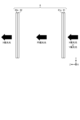
- FIG. 7 is a diagram showing an example of the optical path length of the optical path section 8.
- the wave plate 81 and the half mirror 81a are illustrated separated from each other.
- the rotation direction of circularly polarized light is schematically illustrated by a circular arrow.
- the optical path when X-polarized light enters the optical path section 8 is schematically shown by a black arrow.
- the X-polarized light passes through the wave plate 81 and becomes circularly polarized light. A portion of this circularly polarized light passes through the half mirror 81a, passes through the wavelength plate 83, and becomes X-polarized light. This X-polarized light passes through the reflective polarizing plate 84 and is emitted.
- the light passing through the optical path section 8 passes between the half mirror 81a and the reflective polarizing plate 82a only once (one pass).
- the optical path when Y-polarized light enters the optical path section 8 is schematically shown by a black arrow.
- the Y polarized light passes through the wave plate 81 and becomes circularly polarized light. A portion of this circularly polarized light passes through the half mirror 81a and further passes through the wavelength plate 83 to become Y-polarized light. This Y-polarized light is reflected by the reflective polarizing plate 84, passes through the wavelength plate 83, and becomes circularly polarized light.
- a portion of this circularly polarized light is reflected by the half mirror 81a, passes through the wavelength plate 83, and becomes X-polarized light.
- This X-polarized light passes through the reflective polarizing plate 84 and is emitted.
- the light passing through the optical path section 8 passes between the half mirror 81a and the reflective polarizing plate 82a three times (three passes).
- the optical path length of the Y-polarized light is longer than the optical path length of the X-polarized light when it enters the optical path unit 8. That is, by combining the polarization modulation by the modulation section 5 and the optical path section 8, the optical path length of the light from each part of the display element 2 can be changed. It is also possible to adjust the virtual image position in this way. For example, if the optical path length to make the difference between the two virtual image positions 0.6D is 0.664 m (air length), the thickness of the optical path section 8 is designed to be 0.322 mm (0.644/2). Ru. It is most desirable for the half mirror 81a to have a transmission efficiency of around 38% and a reflection efficiency of around 62%. This is because the efficiency of the single-pass optical path, 38%, and the efficiency of the triple-pass, 62% ⁇ 62% ⁇ 38%, are approximately the same.
- FIG. 8 is a diagram illustrating an example of a schematic configuration of a display device 1 according to a modification.
- the illustrated display device 1 includes two sets of a polarizing plate 4 , a modulating section 5 , an optical path section 6 , and a polarizing plate 7 .
- the polarizing plate 4, modulating section 5, optical path section 6, and polarizing plate 7 related to the second set are referred to as polarizing plate 4-2, modulating section 5-2, optical path section 6-2, and polarizing plate 7-2, and are illustrated in the figure. do.
- a polarizing plate 4-2, a modulating section 5-2, an optical path section 6-2, and a polarizing plate 7-2 are arranged in this order between the polarizing plate 7 and the lens L2.
- the polarizing plate 4-2, the modulating section 5-2, the optical path section 6-2, and the polarizing plate 7-2 may have the same configuration as the polarizing plate 4, the modulating section 5, the optical path section 6, and the polarizing plate 7.
- the thickness of the optical path section 6-2 may be the same as or different from the thickness of the optical path section 6-1.
- the light to be polarized by the modulator 5-2 is the light from each part of the display element 2, and the light that has passed through the optical path section 6 (in this example, the light that has also passed through the polarizing plate 7 and the polarizing plate 4-2). It is.
- the light passing through the optical path section 6-2 is polarization-modulated light by the modulation section 5-2.
- the combination of the polarization modulation by the modulation unit 5 and the optical path unit 6 can provide two different virtual image positions. Two different virtual image positions can also be provided by the combination of the polarization modulation by the modulation section 5-2 and the optical path section 6-2. These combinations can provide three or more, up to four, different virtual image positions. This will be explained with reference to FIG.
- FIG. 9 is a diagram showing an example of polarization modulation by the modulation section 5 and the modulation section 5-2.
- FIG. 9A shows an example of polarization modulation by the modulation section 5.
- FIG. 9B shows an example of polarization modulation by the modulation section 5-2. Note that the liquid crystal and liquid crystal molecules of the modulation section 5-2 are illustrated as a liquid crystal section 51-2 and a liquid crystal molecule 5m-2.
- liquid crystal sections 51 of interest are marked with a diamond mark and a star mark.
- a diamond mark and a star mark are attached to two of the plurality of liquid crystal parts 51-2.
- Liquid crystal section 51 and liquid crystal section 51-2 with the same mark correspond to the same part of display element 2.
- the liquid crystal unit 51 marked with a star mark is driven, and the liquid crystal molecules 5m are aligned at 90 degrees with respect to the X axis (0 degrees with respect to the Y axis). ).
- the light that has passed through the liquid crystal section 51 passes through the optical path section 6 as Y-polarized light.
- the light that has passed through the other liquid crystal section 51 passes through the optical path section 6 as X-polarized light.
- the liquid crystal section 51-2 marked with a diamond mark and the liquid crystal section 51-2 marked with a star mark are driven, and the liquid crystal molecules 5m has an orientation of 90 degrees with respect to the X axis (0 degrees with respect to the Y axis).
- the light that has passed through these liquid crystal sections 51-2 passes through the optical path section 6-2 as Y-polarized light.
- the light that has passed through the other liquid crystal section 51-2 passes through the optical path section 6-2 as X-polarized light.
- the optical path of the light passing through the liquid crystal section 51 and the liquid crystal section 51-2 marked with star marks is the longest.
- the optical path of the light passing through the liquid crystal section 51 and the liquid crystal section 51-2 with the diamond marks becomes longer.
- the optical path of the light that has passed through the other liquid crystal sections 51 and 51-2 is the shortest.
- the refractive index difference in the optical path section 6 is 0.25 and the thickness of the optical path section 6 is 0.8 mm
- the refractive index difference in the optical path section 6-2 is 0.25
- the thickness of the optical path section 6-2 is 0.8 mm.
- the difference between the two virtual image positions obtained by the optical path section 6-2 is 0.6D.
- the total of the optical path section 6 and the optical path section 6-2 is 0.8D.
- the light that has passed through the liquid crystal section 51 and the liquid crystal section 51-2 marked with star marks is Y-polarized light both when it enters the optical path section 6 and when it enters the optical path section 6-2, and the optical path length is the longest. become longer.
- a virtual image position of 0.5D is given.
- the light that has passed through the liquid crystal section 51 and the liquid crystal section 51-2 with diamond marks is X-polarized light when it enters the optical path section 6, and Y-polarized light when it enters the optical path section 6-2. It is light.
- a virtual image position of 0.7D is given.
- the light that has passed through the other liquid crystal sections 51 and 51-2 is X-polarized light both when it is incident on the optical path section 6 and when it is incident on the optical path section 6-2, and the optical path length is the shortest.
- a 1.3D virtual image position is given.
- FIG. 10 is a diagram showing an example of the polarization direction of light in the optical system 3.
- the polarization direction of the light after passing through each of the polarizing plate 4, the modulating section 5, the polarizing plate 7, the polarizing plate 4-2, the modulating section 5-2, and the polarizing plate 7-2 is as follows. Schematically indicated by a white arrow. All of the light that has passed through the polarizing plate 4 is Y-polarized light. The light that has passed through the modulator 5 is either X-polarized light or Y-polarized light. The light that has passed through the polarizing plate 7 is 45 degree polarized light. All of the light that has passed through the polarizing plate 4-2 is Y-polarized light. The light that has passed through the modulator 5-2 is either X-polarized light or Y-polarized light. The light that has passed through the polarizing plate 7-2 is 45 degree polarized light.
- polarization modulation may be performed such that the modulation unit 5 converts the light into Y-polarized light and the modulation unit 5-2 converts it into X-polarized light. Light so polarized may provide yet another virtual image position. As a result, up to four different virtual image positions can be provided (eg 4 focal points VR).
- a wavelength plate may be stacked on the modulation section 5 to achieve a wide wavelength band. This will be explained with reference to FIG.
- FIG. 11 is a diagram showing an example of a schematic configuration of the modulation section 5.
- a wavelength plate 5a is provided for the modulation section 5.
- a wave plate 5a is stacked on the surface of the modulation section 5 on the Z-axis positive direction side.
- the wavelength plate 5a is, for example, a 1/2 wavelength plate with an azimuth axis of 114.5 degrees. It is possible to improve the wavelength characteristics of the modulation section 5 itself, that is, the liquid crystal section 51 itself in which the liquid crystal molecules 5m are arranged. For example, equivalent modulation can be performed over a wide wavelength band such as the RGB band. It becomes possible to improve RGB efficiency and crosstalk.
- the plurality of polarized lights obtained by polarization modulation by the modulator 5 may include polarized lights polarized in a direction between the X-axis direction and the Y-axis direction. This will be explained with reference to FIG.
- FIG. 12 is a diagram showing an example of polarization modulation by the modulation section 5.
- An asterisk is attached to the liquid crystal section 51 in the driven state.
- the liquid crystal molecules 5m have an orientation of 67.5 degrees with respect to the X axis (22.5 degrees with respect to the Y axis).
- the Y-polarized light incident on the liquid crystal section 51 is polarized and modulated to become 45-degree polarized light.
- this light passes through the optical path section 6, since the optical path length in the optical path section 6 is different between the X-polarized light and the Y-polarized light, it behaves as if the optical path length in both cases exists.
- both a 0.5D virtual image position and a 1.1D virtual image position are provided.
- the virtual image positions are superimposed, but due to a psychological effect, the user can view the image as if there was a virtual image position of 0.8D between them.
- the optical system 3 has a triple-pass system configuration including the lens L1, the lens L2, and the lens L3 has been described as an example.
- the triple-pass type configuration is not essential, and various other configurations may be adopted. Examples of other configurations include Fresnel systems, two-panel configurations, and the like.
- the D value is not limited to the values described above, and may be designed to be any various values.
- 0.5D was used as a reference, but design may be performed using 0D as a reference.
- the air portions at both ends of the optical path portion 6 (or the optical path portion 6 and the polarizing plate 7) in the Z-axis direction are portions that can change the virtual image position, so the diopter can be adjusted by adjusting the length of this portion. may be performed. This diopter adjustment may simply be used to correct visual acuity such as nearsightedness and farsightedness.
- the length of the air portions at both ends of the optical path section 6 may be roughly adjusted, and then the virtual image position may be adjusted by the combination of the modulation section 5 and the optical path section 6 as described above. For example, it is possible to further expand the virtual image correction range while reducing the sense of discomfort in close-up views mixed in with distant views.
- the length of the air portions at both ends of the optical path section 6 and the virtual image position (Diopter) do not have a simple proportional relationship, they may be designed with reference to a data table or calculation formula prepared in advance. The same may be applied to the case where the polarization direction by the modulator 5 is determined.
- the portion of the video that the user is viewing may be specified (identified, etc.) by eye sensing. This will be explained with reference to FIG.
- FIG. 13 is a diagram illustrating an example of a schematic configuration of a display device 1 according to a modification.
- FIG. 13A shows a schematic configuration of the display device 1. Note that the configurations of the display element 2 and the optical system 3 are illustrated in a simplified manner.
- the display device 1 further includes a projector 9 and a camera 10 for eye sensing.
- the projector 9 and the camera 10 are arranged at a position where the optical system 3 does not interfere with the light from the display element 2 on which the image is formed.
- the projector 9 emits light toward the user's U eyes, for example.
- An example of light is infrared light.
- the camera 10 detects the light reflected by the user's U pupil and images the eye E based on the light reflected by the user's U pupil.
- FIG. 13B shows an example of the imaged eye E of the user.
- an object point P on the eye E on the pupil
- a Purkinje image is acquired, and thereby the location in the video that the user is viewing is specified.
- the virtual image position may be adjusted based on the results of such eye sensing.
- the interval (pitch) between adjacent liquid crystal sections 51 in the modulation section 5 may be coarser than the interval (for example, pixel pitch) between each part of the display element 2.
- the display element 2 may have a 4K resolution (3840x2160), and the resolution of the modulator 5 may be HD (1280x720), FHD (1920x1080), or the like. This is because while the display element 2 has a direct effect on image quality, the modulation section 5 only changes the virtual image position, and there is no problem even if the degree of fineness is relatively small. For example, even if the aperture ratio of the transmissive liquid crystal of the modulation section 5 is not so high, the low resolution can compensate for this point. The image focus of the modulating section 5 is shifted from that of the display element 2, and in this sense as well, it can be said that there is little need for the modulating section 5 to have high resolution.
- birefringent crystals having different dispersions in XY may be arranged instead of a laminated layer of liquid crystal polymers. Examples include CaCO 3 crystal (calcite), ⁇ -BaB2O4, and the like.
- the optical path section 6 described below may be read as the optical path section 8 as appropriate within the scope of consistency.
- One of the techniques disclosed is the optical system 3.
- the optical system 3 forms an image of the light from the display element 2.
- the optical system 3 includes a modulation section 5 and an optical path section 6.
- the modulator 5 individually polarizes the light from each part of the display element 2 so that the light from each part of the display element 2 becomes one of a plurality of polarized lights having different polarization directions. Modulate.
- the optical path section 6 is a section through which the light polarization-modulated by the modulation section 5 passes.
- the optical path section 6 is configured such that the optical path length of the light passing through the optical path section 6 differs depending on the polarization direction when the light is incident on the optical path section 6.
- the optical path length of the light from each part of the display element 2 can be changed by the combination of the polarization modulation by the modulation section 5 and the optical path section 6. This makes it possible to adjust the virtual image position, making it possible to deal with convergence adjustment contradictions. For example, there is no need to move the display element 2 as in Patent Document 1, and it is possible to suppress the increase in size of the device. It is possible to suppress the increase in size of the device while dealing with congestion adjustment contradictions.
- the modulation section 5 includes a plurality of liquid crystal sections 51 each having a liquid crystal molecule 5m arranged thereon and driven individually. Light from a corresponding part of each part is incident, and driving the liquid crystal part 51 may include changing the state of the liquid crystal molecules 5m arranged in the liquid crystal part 51 (for example, the direction of the liquid crystal molecules 5m). .
- the modulation section 5 having such a configuration can individually polarize the light from each part of the display element 2.
- the optical path section 6 may be configured such that the refractive index of light passing through the optical path section 6 differs depending on the polarization direction of the light.
- the optical path section 6 may include a plurality of liquid crystal molecules 6m arranged in the same direction.
- the optical path length of the light passing through the optical path section 6 can be varied depending on the polarization direction at the time of incidence.
- the optical path section 8 includes a wavelength plate 81 (wave plate 81) that converts the linearly polarized light from the modulator 5 into circularly polarized light according to the polarization direction of the linearly polarized light. 1), a wavelength plate 82 (second wavelength plate) that converts the circularly polarized light from the wavelength plate 81 into linearly polarized light according to the rotation direction of the circularly polarized light, and the wavelength plate 81 and the wavelength plate.
- a wavelength plate 81 wave plate 81
- second wavelength plate that converts the circularly polarized light from the wavelength plate 81 into linearly polarized light according to the rotation direction of the circularly polarized light
- a half mirror 81a disposed between the half mirror 81a and a reflective polarizing plate 82a disposed on the opposite side of the wavelength plate 81 with the wavelength plate 82 in between, which passes a predetermined linearly polarized light and reflects other linearly polarized light; and may include.
- the optical path length of the light passing through the optical path section 8 can be varied depending on the polarization direction at the time of incidence.
- the optical system 3 is disposed between the display element 2 and the modulator 5, and allows only predetermined polarized light to pass among the light from the display element 2.
- a polarizing plate 4 may be provided. Even when the display element 2 emits light containing polarized light in various directions, the polarized light that enters the modulation section 5 can be limited.
- the display element 2 may include an OLED (Organic Light Emitting Diode).
- the optical system 3 includes a polarizing plate that is disposed on the opposite side of the modulation section 5 with the optical path section 6 in between, and that rectifies the light from the optical path section 6 into predetermined polarized light. 7 may be provided. Thereby, the final polarized light after passing through the optical path section 6 can be unified.
- the optical system 3 includes a plurality of lenses for imaging the light from the display element 2, and the plurality of lenses include a lens L1 provided between the modulation section 5 and the optical path section 6, and a lens L1 provided between the modulation section 5 and the optical path section 6 (or the optical path section 6). It may include a lens L2 and a lens L3 that are provided in this order on the opposite side of the modulation section 5 with the optical path section 6 and polarizing plate 7 interposed therebetween. For example, such a triple pass configuration can be adopted.
- the optical system 3 may include the modulation section 5-2 and the optical path section 6-2.
- the modulator 5-2 modulates the display so that the light from each part of the display element 2 that passes through the optical path section 6 becomes one of a plurality of polarized lights having different polarization directions.
- This is a second modulation section that individually polarizes and modulates the light from each part of the element 2 that has passed through the optical path section 6.
- the optical path section 6-2 is a second optical path section through which the light polarization-modulated by the modulation section 5-2 passes.
- the optical path section 6-2 is configured such that the optical path length of the light passing through the optical path section 6-2 differs depending on the polarization direction of the light when it enters the optical path section 6-2. Thereby, more different virtual image positions can be provided than in the case where only one modulation section 5 and one optical path section 6 are provided.
- the modulation section 5 may have a wave plate 5a laminated thereon. This makes it possible to widen the wavelength band.
- the display element 2 extends in the XY plane direction, and the plurality of polarized lights obtained by polarization modulation of the modulation unit 5 are polarized in the X-axis direction. It may include X-polarized light and Y-polarized light polarized in the Y-axis direction. For example, by using such polarized light, the optical path length of light from each part of the display element 2 can be changed to provide different virtual image positions. As described with reference to FIG. 12 and the like, the plurality of polarized lights may include polarized lights polarized in a direction between the X-axis direction and the Y-axis direction. Thereby, different virtual image positions can be mixed to provide a virtual image position in a pseudo intermediate state.
- the display device 1 described with reference to FIGS. 1 to 7 and the like is also one of the disclosed technologies.
- the display device 1 includes a display element 2 and an optical system 3 that forms an image of light from the display element 2.
- the optical system 3 is as described above. With such a display device 1, as described above, it is possible to suppress the increase in size of the device while dealing with the convergence adjustment contradiction.
- the display device 1 may include the camera 10 for eye sensing. For example, it becomes possible to adjust the virtual image position based on the results of eye sensing.
- the present technology can also have the following configuration.
- An optical system that images light from a display element, a modulator that individually polarizes and modulates the light from each part of the display element so that the light from each part of the display element becomes one of a plurality of polarized lights having different polarization directions; , an optical path section through which the light polarization-modulated by the modulation section passes; Equipped with The optical path section is configured such that the optical path length of the light passing through the optical path section varies depending on the polarization direction when the light enters the optical path section.
- Optical system that images light from a display element, a modulator that individually polarizes and modulates the light from each part of the display element so that the light from each part of the display element becomes one of a plurality of polarized lights having different polarization directions; , an optical path section through which the light polarization-modulated by the modulation section passes; Equipped with The optical path section is configured such that the optical path length of the light passing through the optical
- the modulation unit includes a plurality of liquid crystal units each having liquid crystal molecules arranged therein and driven individually; Light from a corresponding portion of each portion of the display element is incident on each of the plurality of liquid crystal portions,
- the driving of the liquid crystal section includes changing the state of the liquid crystal molecules arranged in the liquid crystal section.
- the state of the liquid crystal molecules includes the orientation of the liquid crystal molecules, The optical system described in (2).
- the optical path section is configured such that the refractive index of light passing through the optical path section differs depending on the polarization direction of the light.
- the optical system according to any one of (1) to (3).
- the optical path section includes a plurality of liquid crystal molecules arranged in the same direction. The optical system described in (4).
- the optical path section is a first wavelength plate that converts the linearly polarized light from the modulation section into circularly polarized light according to the polarization direction of the linearly polarized light; a second wavelength plate that converts the circularly polarized light from the first wavelength plate into linearly polarized light according to the rotation direction of the circularly polarized light; a half mirror disposed between the first wave plate and the second wave plate; a reflective polarizing plate that is disposed on the opposite side of the first wavelength plate with the second wavelength plate in between and passes a predetermined linearly polarized light and reflects other linearly polarized light; including, The optical system according to any one of (1) to (3).
- the optical system according to any one of (1) to (6).
- the display element includes an OLED (Organic Light Emitting Diode).
- the optical system according to any one of (1) to (7). (9) comprising a polarizing plate disposed on the opposite side of the modulation section across the optical path section and rectifying the light from the optical path section into predetermined polarized light;
- the plurality of lenses are a lens provided between the modulation section and the optical path section; two lenses provided in order on the opposite side of the modulation section across the optical path section; including, The optical system according to any one of (1) to (9).
- the light from each part of the display element is configured such that the light from each part of the display element that passes through the optical path becomes one of a plurality of polarized lights having different polarization directions.
- a second modulation section that individually polarizes and modulates the light that has passed through the optical path section; a second optical path section through which the light polarization-modulated by the second modulation section passes; Equipped with The second optical path section is configured such that the optical path length of the light passing through the optical path section varies depending on the polarization direction when the light enters the second optical path section.
- the display element extends in the XY plane direction,
- the plurality of polarized lights obtained by polarization modulation of the modulation unit include X-polarized light polarized in the X-axis direction and Y-polarized light polarized in the Y-axis direction.
- the display element extends in the XY plane direction,
- the plurality of polarized lights obtained by polarization modulation of the modulation unit include polarized lights polarized in a direction between an X-axis direction and a Y-axis direction.
- the optical system according to any one of (1) to (13).
- a display element an optical system that images light from the display element; Equipped with The optical system is a modulator that individually polarizes and modulates the light from each part of the display element so that the light from each part of the display element becomes one of a plurality of polarized lights having different polarization directions; , an optical path section through which the light polarization-modulated by the modulation section passes; including; The optical path section is configured such that the optical path length of the light passing through the optical path section varies depending on the polarization direction when the light enters the optical path section.
- Display device (16) Equipped with a camera for eye sensing, The display device according to (15).
Abstract
One aspect of the present disclosure suppresses upsizing of a device while dealing with a vergence-accommodation conflict. An optical system (3) for forming an image of light from a display element (2) comprises: a modulation part (5) which individually polarizes and modulates light from each portion of the display element such that the light from each portion of the display element becomes any polarized light beam among a plurality of polarized light beams with different polarization directions; and an optical path part (6) through which the light polarized and modulated by the modulation part passes. The optical path part is configured such that the optical path length of the light passing through the optical path part differs according to the polarization direction when the light is incident on the optical path part.
Description
本開示は、光学系及び表示装置に関する。
The present disclosure relates to an optical system and a display device.
HMD(Head Mount Display)等における輻輳調整矛盾に対処するための技術が提案されている。例えば特許文献1は、輻輳角と視度とが一致するように液晶ディスプレイを光軸方向に移動させる技術を開示する。
Techniques have been proposed to deal with congestion adjustment conflicts in HMDs (Head Mount Displays) and the like. For example, Patent Document 1 discloses a technique for moving a liquid crystal display in the optical axis direction so that the convergence angle and the diopter match.
液晶ディスプレイのような表示素子を光軸方向に移動させると、その分装置が大型化する。
If a display element such as a liquid crystal display is moved in the optical axis direction, the device becomes larger.
本開示の一側面は、輻輳調整矛盾に対処しつつ装置の大型化を抑制する。
One aspect of the present disclosure suppresses device enlargement while addressing congestion adjustment contradictions.
本開示の一側面に係る光学系は、表示素子からの光を結像する光学系であって、表示素子の各部分からの光が、偏光方向の異なる複数の偏光光のうちのいずれかの偏光光になるように、表示素子の各部分からの光を個別に偏光変調する変調部と、変調部によって偏光変調された光が通過する光路部と、を備え、光路部は、当該光路部を通過する光の光路長が、当該光が当該光路部に入射したときの偏光方向によって異なるように構成される。
An optical system according to one aspect of the present disclosure is an optical system that images light from a display element, and the light from each part of the display element is one of a plurality of polarized lights having different polarization directions. A modulation section that individually polarizes and modulates the light from each part of the display element so that it becomes polarized light, and an optical path section through which the light polarization-modulated by the modulation section passes. The optical path length of the light passing through the optical path section is configured to vary depending on the polarization direction when the light enters the optical path section.
本開示の一側面に係る表示装置は、表示素子と、表示素子からの光を結像する光学系と、を備え、光学系は、表示素子の各部分からの光が、偏光方向の異なる複数の偏光光のうちのいずれかの偏光光になるように、表示素子の各部分からの光を個別に偏光変調する変調部と、変調部によって偏光変調された光が通過する光路部と、を含み、光路部は、当該光路部を通過する光の光路長が、当該光が当該光路部に入射したときの偏光方向によって異なるように構成される。
A display device according to an aspect of the present disclosure includes a display element and an optical system that images light from the display element, and the optical system allows light from each part of the display element to be divided into multiple polarization directions. a modulator that individually polarize-modulates the light from each part of the display element so that the polarized light becomes one of the polarized lights, and an optical path section through which the light polarization-modulated by the modulator passes. The optical path section is configured such that the optical path length of light passing through the optical path section differs depending on the polarization direction of the light when it enters the optical path section.
以下に、本開示の実施形態について図面に基づいて詳細に説明する。なお、以下の各実施形態において、同一の要素には同一の符号を付することにより重複する説明を省略する。
Below, embodiments of the present disclosure will be described in detail based on the drawings. In addition, in each of the following embodiments, the same elements are given the same reference numerals to omit redundant explanation.
以下に示す項目順序に従って本開示を説明する。
0.序
1.実施形態
2.変形例
3.効果の例 The present disclosure will be described according to the order of items shown below.
0.Introduction 1. Embodiment 2. Modification example 3. Example of effect
0.序
1.実施形態
2.変形例
3.効果の例 The present disclosure will be described according to the order of items shown below.
0.
0.序
例えばVR(Virtual Reality)向けHMD等の光学系では、眼の焦点と両眼視差とが異なる輻輳調整矛盾への対処が重要である。一案として、アイセンシングで検出した目線方向に虚像位置を与えるようにフォーカシング機構を駆動することが考えられる。ただし、非常に精密なアイセンシングが求められる。また、特許文献1のように表示素子を移動させるフォーカシング機構では、装置が大型化する。別の案として、各々が異なる虚像位置を与える複数のパネルを用いる技術もあるが、やはり装置の大型化を招く等の課題がある。 0. Introduction For example, in optical systems such as HMDs for VR (Virtual Reality), it is important to deal with convergence adjustment contradictions in which the focus of the eyes and the binocular parallax are different. One idea is to drive the focusing mechanism so as to give the virtual image position in the line of sight direction detected by eye sensing. However, extremely precise eye sensing is required. Furthermore, in the focusing mechanism that moves the display element as inPatent Document 1, the device becomes large. As another idea, there is a technique using a plurality of panels, each of which provides a different virtual image position, but this also has problems such as increasing the size of the device.
例えばVR(Virtual Reality)向けHMD等の光学系では、眼の焦点と両眼視差とが異なる輻輳調整矛盾への対処が重要である。一案として、アイセンシングで検出した目線方向に虚像位置を与えるようにフォーカシング機構を駆動することが考えられる。ただし、非常に精密なアイセンシングが求められる。また、特許文献1のように表示素子を移動させるフォーカシング機構では、装置が大型化する。別の案として、各々が異なる虚像位置を与える複数のパネルを用いる技術もあるが、やはり装置の大型化を招く等の課題がある。 0. Introduction For example, in optical systems such as HMDs for VR (Virtual Reality), it is important to deal with convergence adjustment contradictions in which the focus of the eyes and the binocular parallax are different. One idea is to drive the focusing mechanism so as to give the virtual image position in the line of sight direction detected by eye sensing. However, extremely precise eye sensing is required. Furthermore, in the focusing mechanism that moves the display element as in
開示される技術によれば、表示素子の各部分(各位置)からの光に対応する虚像位置の個別調整が可能であり、それによって輻輳調整矛盾に対処できる。アイセンシングは必須ではなく、また、フォーカシング機構が不要であることから、装置の小型化、軽量化が可能である。これまで以上に酔いにくく、違和感の少ない自然なVRを提供できる可能性も高まる。
According to the disclosed technology, it is possible to individually adjust the virtual image position corresponding to the light from each part (each position) of the display element, thereby making it possible to deal with convergence adjustment contradictions. Eye sensing is not essential, and since a focusing mechanism is not required, the device can be made smaller and lighter. The possibility of providing natural VR that is less likely to cause motion sickness and discomfort than ever before is also increasing.
1.実施形態
図1は、実施形態に係る表示装置1の概略構成の例を示す図である。表示装置1は、例えばVR等の映像を提示するHMDであり、ユーザの頭部に装着されて用いられる。映像は画像を含む意味に解されてよく、矛盾の無い範囲において、映像及び画像は適宜読み替えられてよい。ユーザの眼部を、ユーザの眼部Eと称し図示する。表示装置1が提示する映像は、ユーザの眼部Eによって観察される。 1. Embodiment FIG. 1 is a diagram showing an example of a schematic configuration of adisplay device 1 according to an embodiment. The display device 1 is, for example, an HMD that presents images such as VR, and is used by being worn on a user's head. The term "video" may be interpreted to include images, and the terms "video" and "image" may be interpreted as appropriate to the extent that there is no contradiction. The user's eye is referred to as user's eye E in the figure. The image presented by the display device 1 is observed by the eye E of the user.
図1は、実施形態に係る表示装置1の概略構成の例を示す図である。表示装置1は、例えばVR等の映像を提示するHMDであり、ユーザの頭部に装着されて用いられる。映像は画像を含む意味に解されてよく、矛盾の無い範囲において、映像及び画像は適宜読み替えられてよい。ユーザの眼部を、ユーザの眼部Eと称し図示する。表示装置1が提示する映像は、ユーザの眼部Eによって観察される。 1. Embodiment FIG. 1 is a diagram showing an example of a schematic configuration of a
図において、XYZ座標系が示される。Z軸正方向に、表示装置1及びユーザの眼部Eがこの順に位置する。表示装置1の各要素は、XY平面方向に延在し、Z軸方向に厚さを有する。図1の(A)及び(B)には、X軸方向にみたときの表示装置1の側面(断面であってもよい)が模式的に示される。図1の(B)には、いくつかの光の経路が模式的に示される。
In the figure, an XYZ coordinate system is shown. The display device 1 and the user's eye E are located in this order in the positive direction of the Z-axis. Each element of the display device 1 extends in the XY plane direction and has a thickness in the Z axis direction. 1A and 1B schematically show a side surface (or a cross section) of the display device 1 when viewed in the X-axis direction. FIG. 1B schematically shows several light paths.
本開示において、X軸方向に偏光された偏光光を、X偏光光とも称する。Y軸方向に偏光された偏光光を、Y偏光光とも称する。X軸方向及びY軸方向に対して45度の方向に偏光された偏光光を、45度偏光光とも称する。なお、偏光光には、直線偏光光及び円偏光光があるが、とくに説明がある場合を除き、単に偏光光という場合は、直線偏光光の意味に解されてよい。
In the present disclosure, polarized light polarized in the X-axis direction is also referred to as X-polarized light. Polarized light polarized in the Y-axis direction is also referred to as Y-polarized light. Polarized light polarized in a direction of 45 degrees with respect to the X-axis direction and the Y-axis direction is also referred to as 45-degree polarized light. Note that polarized light includes linearly polarized light and circularly polarized light, but unless otherwise specified, the term simply polarized light may be interpreted to mean linearly polarized light.
表示装置1は、表示素子2と、光学系3とを含む。Z軸正方向に、表示素子2及び光学系3がこの順に配置される。
The display device 1 includes a display element 2 and an optical system 3. The display element 2 and the optical system 3 are arranged in this order in the positive direction of the Z-axis.
表示素子2は、映像を構成する光を出射する。表示素子2は、XY平面方向を面方向とし、Z軸負方向側に表示面を有する表示パネルである。表示素子2は、例えば、OLED(Organic Light Emitting Diode)、LC(Liquid Crystal)、LED(Light Emitting Diode)等を含んで構成される。
The display element 2 emits light that forms an image. The display element 2 is a display panel that has the XY plane direction as its surface direction and a display surface on the Z-axis negative direction side. The display element 2 includes, for example, an OLED (Organic Light Emitting Diode), an LC (Liquid Crystal), an LED (Light Emitting Diode), and the like.
表示素子2は、各々が独立に発光制御される複数の部分を含む。典型的には、表示素子2の1つの部分は、表示素子2の1つのピクセルである。
The display element 2 includes a plurality of parts, each of which is independently controlled to emit light. Typically, one portion of the display element 2 is one pixel of the display element 2.
光学系3は、表示素子2からの光を結像する。光学系3は、偏光板4と、変調部5と、光路部6と、偏光板7と、他の光学系とを含む。他の光学系として、レンズL1、レンズL2、レンズL3及び平板Bが例示される。Z軸正方向に、偏光板4、変調部5、レンズL1、光路部6、偏光板7、レンズL2、レンズL3及び平板Bがこの順に配置される。表示素子2からの光は、これらの要素を順に通り、ユーザが眼部Eで虚像を観察するように結像される。
The optical system 3 forms an image of the light from the display element 2. The optical system 3 includes a polarizing plate 4, a modulation section 5, an optical path section 6, a polarizing plate 7, and other optical systems. Other optical systems include a lens L1, a lens L2, a lens L3, and a flat plate B. Polarizing plate 4, modulating section 5, lens L1, optical path section 6, polarizing plate 7, lens L2, lens L3, and flat plate B are arranged in this order in the positive direction of the Z-axis. Light from the display element 2 passes through these elements in order and is imaged so that the user observes a virtual image with the eye E.
偏光板4は、表示素子2及び変調部5の間に配置される。偏光板4は、例えばポラライザ、ワイヤーグリッド偏光子等であり、表示素子2からの光のうち、所定の偏光光だけを通過させる。これにより、変調部5に入射する偏光光を限定することができる。例えば、表示素子2がさまざまな偏光光を含む光を発するOLEDを含んで構成される場合等に有効である。表示素子2が特定の偏光光を含む光だけを発するLCDを含んで構成される場合等には、偏光板4は無くてもよい。以下では、とくに説明がある場合を除き、偏光板4が通過させる所定の偏光光は、Y偏光光であるものとする。
The polarizing plate 4 is arranged between the display element 2 and the modulation section 5. The polarizing plate 4 is, for example, a polarizer, a wire grid polarizer, or the like, and allows only predetermined polarized light out of the light from the display element 2 to pass through. Thereby, the polarized light that enters the modulation section 5 can be limited. For example, this is effective when the display element 2 includes an OLED that emits light containing various polarized lights. In the case where the display element 2 includes an LCD that emits only light containing a specific polarized light, the polarizing plate 4 may be omitted. In the following description, it is assumed that the predetermined polarized light that the polarizing plate 4 passes is Y-polarized light, unless otherwise specified.
変調部5は、表示素子2からの光(この例では偏光板4からの光)を偏光変調する。変調部5は、表示素子2の各部分からの光が、偏光方向の異なる複数の偏光光のうちのいずれかの偏光光になるように、表示素子2の各部分からの光を個別に偏光変調する。複数の偏光光の例は、X偏光光及びY偏光光等である。とくに説明がある場合を除き、変調部5は、表示素子2の各部分からの光を、X偏光光及びY偏光光のいずれかに個別に偏光変調するものとする。変調部5について、図2も参照して説明する。
The modulator 5 polarizes and modulates the light from the display element 2 (in this example, the light from the polarizing plate 4). The modulator 5 individually polarizes the light from each part of the display element 2 so that the light from each part of the display element 2 becomes one of a plurality of polarized lights having different polarization directions. Modulate. Examples of the plurality of polarized lights include X-polarized light and Y-polarized light. Unless otherwise specified, the modulator 5 polarizes the light from each portion of the display element 2 individually into either X-polarized light or Y-polarized light. The modulator 5 will be explained with reference to FIG. 2 as well.
図2は、変調部5の概略構成の例を示す図である。Z軸負方向にみたときの変調部5が模式的に示される。なお、図において、X軸方向に延在する白抜き矢印は、X偏光光を模式的に示す。Y軸方向に延在する白抜き矢印は、Y偏光光を模式的に示す。変調部5は、例えば、面内に液晶分子が配向された変調液晶パネルから偏光板を取り除いた構成と同様の構成を備える。
FIG. 2 is a diagram showing an example of a schematic configuration of the modulation section 5. The modulation unit 5 is schematically shown when viewed in the negative Z-axis direction. Note that in the figure, a white arrow extending in the X-axis direction schematically indicates X-polarized light. A white arrow extending in the Y-axis direction schematically indicates Y-polarized light. The modulator 5 has, for example, a configuration similar to that of a modulation liquid crystal panel in which liquid crystal molecules are aligned in-plane, with the polarizing plate removed.
変調部5は、複数の液晶部51を含む。各液晶部51は、表示素子2の各部分に対応する。複数の液晶部51それぞれに、表示素子2の各部分のうちの対応する部分からの光が入射する。各液晶部51には、1つ以上の液晶分子5mが配置される。表示素子2の各部分からの光は、対応する液晶部51に配置された液晶分子5mを通過する。
The modulation section 5 includes a plurality of liquid crystal sections 51. Each liquid crystal section 51 corresponds to each part of the display element 2. Light from a corresponding portion of each portion of the display element 2 enters each of the plurality of liquid crystal portions 51 . In each liquid crystal section 51, one or more liquid crystal molecules 5m are arranged. Light from each part of the display element 2 passes through liquid crystal molecules 5m arranged in the corresponding liquid crystal section 51.
各液晶部51は、個別に駆動される。例えば、各液晶部51への電圧印加が個別に制御される。液晶部51の駆動は、液晶部51に配置された液晶分子5mの状態を変えることを含む。液晶分子5mの状態の一例は、液晶分子5mの向きである。
Each liquid crystal section 51 is driven individually. For example, voltage application to each liquid crystal section 51 is individually controlled. Driving the liquid crystal section 51 includes changing the state of the liquid crystal molecules 5m arranged in the liquid crystal section 51. An example of the state of the liquid crystal molecules 5m is the orientation of the liquid crystal molecules 5m.
図2に示される例では、液晶分子5mは、電圧が印加されず駆動されていない状態(デフォルト状態)で、X軸及びY軸に対して45度の向きを有する。付与位相差は1/2波長であるものとする。この液晶部51に偏光板4からのY偏光光が入射すると、そのY偏光光は、X偏光光に変換されて出射される。反対に、液晶分子5mは、電圧が印可され駆動されている状態(駆動状態)では、X軸に対して90度(Y軸に対して0度)の向きを有する。この液晶部51に入射したY偏光光は、そのままY偏光光として出射される。
In the example shown in FIG. 2, the liquid crystal molecules 5m have an orientation of 45 degrees with respect to the X-axis and the Y-axis when no voltage is applied and they are not driven (default state). It is assumed that the applied phase difference is 1/2 wavelength. When Y-polarized light from the polarizing plate 4 enters the liquid crystal section 51, the Y-polarized light is converted into X-polarized light and output. On the contrary, the liquid crystal molecules 5m have an orientation of 90 degrees with respect to the X axis (0 degrees with respect to the Y axis) when a voltage is applied and the liquid crystal molecules 5m are driven (driving state). The Y-polarized light that has entered the liquid crystal section 51 is directly output as Y-polarized light.
例えば上記の構成を備えることにより、変調部5は、各液晶部51を通過した光、すなわち表示素子2の各部分からの光を、X偏光光及びY偏光光のいずれかに個別に偏光変調する。後述の原理により、ここでのX偏光光及びY偏光光の選択が、虚像位置(奥行)の変化を与える。
For example, by having the above configuration, the modulation unit 5 individually polarizes the light that has passed through each liquid crystal unit 51, that is, the light from each part of the display element 2, into either X-polarized light or Y-polarized light. do. Based on the principle described below, the selection of the X-polarized light and the Y-polarized light here changes the virtual image position (depth).
なお、例えばRGBを含むような広帯域にわって1/2波長の付与位相差を実現するように、変調部5は、各層が異なる位相量、位相軸角を有する複数の層を含んで構成されてもよい。
Note that, in order to realize an imparted phase difference of 1/2 wavelength over a wide band including, for example, RGB, the modulator 5 is configured to include a plurality of layers, each layer having a different phase amount and phase axis angle. You can.
図1に戻り、変調部5からの光は、レンズL1を通過する。例示されるレンズL1は、非球面レンズであり、変調部5及び光路部6の間に設けられる。レンズL1は、入射角が出射角よりも(例えば5度以上)大きくなるように設計されてよい。最大画角の主光線の内側への曲げ量を確保することができ、像面性を維持しながら視度調整を行うことができる。レンズL1を通過した光は、光路部6に入射する。
Returning to FIG. 1, the light from the modulation section 5 passes through the lens L1. The illustrated lens L1 is an aspherical lens, and is provided between the modulation section 5 and the optical path section 6. Lens L1 may be designed such that the angle of incidence is larger (for example, 5 degrees or more) than the angle of exit. It is possible to ensure the amount of inward bending of the chief ray at the maximum angle of view, and it is possible to adjust the diopter while maintaining the image plane. The light that has passed through the lens L1 enters the optical path section 6.
光路部6は、変調部5によって偏光変調された光(この例ではレンズL1からの光)が通過する部分である。光路部6は、光路部6を通過する光の光路長が、その光が光路部6に入射したときの偏光方向によって異なるように構成される。例えば、光路部6は、光路部6を通過する光の屈折率が当該光の偏光方向によって異なるように構成される。図3を参照して説明する。
The optical path section 6 is a section through which the light polarization-modulated by the modulation section 5 (in this example, the light from the lens L1) passes. The optical path section 6 is configured such that the optical path length of the light passing through the optical path section 6 differs depending on the polarization direction when the light is incident on the optical path section 6. For example, the optical path section 6 is configured such that the refractive index of light passing through the optical path section 6 differs depending on the polarization direction of the light. This will be explained with reference to FIG.
図3は、光路部6の概略構成の例を示す図である。Z軸負方向にみたときの光路部6が模式的に示される。光路部6は、複数の液晶分子6mを含む。複数の液晶分子6mは、通過する光の屈折率がその光の偏光方向によって異なるように配置される。複数の液晶分子6mは、例えばポリマー液晶であり、いずれも同じ向きに配置される。
FIG. 3 is a diagram showing an example of a schematic configuration of the optical path section 6. The optical path portion 6 when viewed in the negative Z-axis direction is schematically shown. The optical path section 6 includes a plurality of liquid crystal molecules 6m. The plurality of liquid crystal molecules 6m are arranged so that the refractive index of the light passing therethrough varies depending on the polarization direction of the light. The plurality of liquid crystal molecules 6m are, for example, polymer liquid crystals, and are all arranged in the same direction.
図3に示される例では、複数の液晶分子6mは、X軸に対して0度の向き(Y軸に対して90度の向き)を有する。光路部6は、X偏光光及びY偏光光に対して互いに異なる屈折率を与える。具体的に、X偏光光の屈折率よりも、Y偏光光の屈折率が高くなる。例えば、X偏光光の屈折率が1.52であり、Y偏光光の屈折率が1.77になる。屈折率差は0.25である。
In the example shown in FIG. 3, the plurality of liquid crystal molecules 6m have an orientation of 0 degrees with respect to the X axis (orientation of 90 degrees with respect to the Y axis). The optical path section 6 gives mutually different refractive indexes to the X-polarized light and the Y-polarized light. Specifically, the refractive index of Y-polarized light is higher than the refractive index of X-polarized light. For example, the refractive index of X-polarized light is 1.52, and the refractive index of Y-polarized light is 1.77. The refractive index difference is 0.25.
屈折率差に起因して、光路部6を通過するX偏光光の光路長及びY偏光光の光路長が互いに異なる。上記の例では、X偏光光の光路長よりも、Y偏光光の光路長が長くなる。すなわち、先の変調部5による偏光変調と光路部6とを組み合わせることで、表示素子2の各部分からの光の光路長を変化させることができる。光路部6を通過する光の光路長は、光学系3のフォーカス調整間隔に相当し、結果として、虚像位置(Diopter)の変化を与える。例えば、光路長が短い光によって構成された虚像が手前に位置するように観察され、光路長が長い光によって構成された虚像が奥に位置するように観察される。虚像位置の調整が可能になる。
Due to the difference in refractive index, the optical path length of the X-polarized light and the optical path length of the Y-polarized light passing through the optical path section 6 are different from each other. In the above example, the optical path length of Y-polarized light is longer than the optical path length of X-polarized light. That is, by combining the polarization modulation by the modulation section 5 and the optical path section 6, the optical path length of the light from each part of the display element 2 can be changed. The optical path length of the light passing through the optical path unit 6 corresponds to the focus adjustment interval of the optical system 3, and as a result, changes the virtual image position (Diopter). For example, a virtual image formed by light with a short optical path length is observed to be located in the front, and a virtual image formed by light with a long optical path length is observed to be located in the back. The virtual image position can be adjusted.
X偏光光の場合の虚像位置と、Y偏光光の場合の虚像位置との差は、光路部6の厚さ(Z軸方向の長さ)に起因する。それら2つの虚像位置の所望の差が得られるように、光路部6の厚さが設計される。例えば、上述のように屈折率差が0.25であり、2つの虚像位置の差を0.6D(DはDiopter値)にするための光路長が0.664m(空気長)の場合、光路部6の厚さは、2.655mm(0.644/0.25)に設計される。
The difference between the virtual image position in the case of X-polarized light and the virtual image position in the case of Y-polarized light is due to the thickness (length in the Z-axis direction) of the optical path section 6. The thickness of the optical path section 6 is designed so that a desired difference between the two virtual image positions can be obtained. For example, as mentioned above, if the refractive index difference is 0.25 and the optical path length is 0.664 m (air length) to make the difference between the two virtual image positions 0.6 D (D is the diopter value), the optical path The thickness of the portion 6 is designed to be 2.655 mm (0.644/0.25).
図1に戻り、偏光板7は、光路部6(この例では光路部6及びレンズL1)を挟んで変調部5とは反対側に配置され、光路部6からの光を所定の偏光光に整流する。これにより、光路部6を通過した後の光の最終的な偏光光を統一することができる。例えばレンズL1、レンズL2及びレンズL3を含む構成(トリプルパス構成)を採用することができる。とくに説明がある場合を除き、偏光板7は、光路部6からの光が45度偏光光になるように、光路部6からの光を整流するものとする。偏光板7は、例えば45度の方位角を有するように配置される。
Returning to FIG. 1, the polarizing plate 7 is disposed on the opposite side of the modulating section 5 with the optical path section 6 (in this example, the optical path section 6 and the lens L1) in between, and converts the light from the optical path section 6 into predetermined polarized light. rectify. Thereby, the final polarized light of the light after passing through the optical path section 6 can be unified. For example, a configuration including a lens L1, a lens L2, and a lens L3 (triple pass configuration) can be adopted. Unless otherwise specified, the polarizing plate 7 rectifies the light from the optical path section 6 so that the light from the optical path section 6 becomes 45-degree polarized light. The polarizing plate 7 is arranged to have an azimuth angle of, for example, 45 degrees.
偏光板7からの光は、レンズL2、レンズL3及び平板Bを通過する。レンズL2及びレンズL3は、偏光板7からの光を結像するように設計された非球面レンズであり、光路部6及び偏光板7を挟んで変調部5とは反対側に順に設けられる。レンズL2は正の屈折力(焦点距離>0)に構成され、レンズL3は負の屈折力(焦点距離<0)に構成されてよい。色収差等の収差の調整を容易に行うことができる。レンズL3のd線における屈折率は、レンズL2の屈折率よりも大きくてよい。レンズL3のd線におけるアッベ数は、レンズL2のアッベ数よりも小さくてよい。倍率色収差を有効に補正することができる。平板Bは、レンズL3からの光を透過させる透明平板である。平板Bの表面(例えばZ軸負方向側の面)は、入射した光の一部を反射させ、一部を通過させる半透過反射面であってよい。例えばハーフミラーが用いられてよい。
The light from the polarizing plate 7 passes through the lens L2, the lens L3, and the flat plate B. Lens L2 and lens L3 are aspherical lenses designed to form an image of the light from polarizing plate 7, and are provided in order on the opposite side of modulation unit 5 with optical path unit 6 and polarizing plate 7 in between. Lens L2 may be configured with positive refractive power (focal length >0) and lens L3 may be configured with negative refractive power (focal length <0). Aberrations such as chromatic aberration can be easily adjusted. The refractive index of the lens L3 at the d-line may be greater than the refractive index of the lens L2. The Abbe number of the lens L3 at the d-line may be smaller than the Abbe number of the lens L2. Lateral chromatic aberration can be effectively corrected. The flat plate B is a transparent flat plate that transmits the light from the lens L3. The surface of the flat plate B (for example, the surface on the negative side of the Z-axis) may be a transflective surface that reflects part of the incident light and allows part of it to pass through. For example, a half mirror may be used.
例示される光学系3は、表示素子2からの光がレンズL1、レンズL2及びレンズL3の3つのレンズを通過するトリプルパス構成を備える。このような構成により、光学系3の薄型化、小型化が図られる。
The illustrated optical system 3 has a triple-pass configuration in which light from the display element 2 passes through three lenses: a lens L1, a lens L2, and a lens L3. With such a configuration, the optical system 3 can be made thinner and smaller.
図4は、光学系3における光の偏光方向の例を示す図である。光学系3の構成要素のうち、偏光板4、変調部5及び偏光板7それぞれを通過した後の光の偏光方向が、白抜き矢印で模式的に示される。偏光板4を通過した光は、いずれもY偏光光である。変調部5を通過した光は、X偏光光及びY偏光光のいずれかである。偏光板7を通過した光は、45度偏光光である。
FIG. 4 is a diagram showing an example of the polarization direction of light in the optical system 3. Among the components of the optical system 3, the polarization directions of the light after passing through the polarizing plate 4, the modulating section 5, and the polarizing plate 7 are schematically indicated by white arrows. All of the light that has passed through the polarizing plate 4 is Y-polarized light. The light that has passed through the modulator 5 is either X-polarized light or Y-polarized light. The light that has passed through the polarizing plate 7 is 45 degree polarized light.
以上で説明した光学系3を備える表示装置1によれば、変調部5による偏光変調及び光路部6の組合せによって、表示素子2の各部分からの光の光路長を変化させることができる。これにより虚像位置を調整できるようになるので、輻輳調整矛盾への対処が可能になる。アイセンシングは必須ではなく、また、フォーカシング機構が不要な分、小型化、軽量化も可能である。従って、輻輳調整矛盾に対処しつつ装置の大型化を抑制することができる。
According to the display device 1 equipped with the optical system 3 described above, the optical path length of light from each part of the display element 2 can be changed by the combination of the polarization modulation by the modulation section 5 and the optical path section 6. This makes it possible to adjust the virtual image position, making it possible to deal with convergence adjustment contradictions. Eye sensing is not essential, and since a focusing mechanism is not required, the camera can be made smaller and lighter. Therefore, it is possible to suppress the increase in size of the device while dealing with the congestion adjustment contradiction.
また、アイセンシングやフォーカシング機構の駆動に関する処理が不要になるので、信号処理負担も軽減される。発熱量が低減され、バッテリーによる長時間動作も可能になる。
Furthermore, since processing related to eye sensing and driving of the focusing mechanism is no longer necessary, the burden of signal processing is also reduced. The amount of heat generated is reduced, and long-term battery operation is possible.
より美しい映像提示も可能になる。とくに手前の像と奥の像が複雑に混在するような映像に対応し易いというメリットがある。例えば、VR光学系に対して複数枚パネルを使用するような手法では、Z軸方向におけるパネルどうしの位置を相当近づける必要があり、また、収差補正も困難になる。ビームスプリッタで二枚を合成する場合は、高解像度広視野角ではバックフォーカスが無く、組み入れることができない。こういった問題も、実施形態に係る表示装置1では対処することができる。
It also becomes possible to present more beautiful images. In particular, this method has the advantage of being easily applicable to images in which images in the foreground and images in the background are mixed in a complex manner. For example, in a method of using a plurality of panels for the VR optical system, it is necessary to position the panels quite close to each other in the Z-axis direction, and it is also difficult to correct aberrations. When combining two images using a beam splitter, there is no back focus at high resolution and a wide viewing angle, so it cannot be incorporated. These problems can also be addressed with the display device 1 according to the embodiment.
光路部6による収差の影響は軽微である。例えば、映像中の異なる虚像位置に調整された部分それぞれの空間周波数に対するコントラスト特性は、いずれも実用上問題ない範囲に収まる。倍率色収差についても同様である。
The influence of aberrations caused by the optical path section 6 is slight. For example, the contrast characteristics with respect to the spatial frequencies of the portions of the video that are adjusted to different virtual image positions are all within a range that poses no problem for practical use. The same applies to lateral chromatic aberration.
2.変形例
開示される技術は、上記の実施形態に限定されない。いくつかの変形例について述べる。例えば、光路部の構成は、上記の光路部6の構成と別の構成であってもよい。図5~図8を参照して説明する。 2. Modifications The disclosed technology is not limited to the above embodiments. Some modifications will be described. For example, the configuration of the optical path section may be different from the configuration of theoptical path section 6 described above. This will be explained with reference to FIGS. 5 to 8.
開示される技術は、上記の実施形態に限定されない。いくつかの変形例について述べる。例えば、光路部の構成は、上記の光路部6の構成と別の構成であってもよい。図5~図8を参照して説明する。 2. Modifications The disclosed technology is not limited to the above embodiments. Some modifications will be described. For example, the configuration of the optical path section may be different from the configuration of the
図5は、変形例に係る表示装置1の概略構成の例を示す図である。図5に示される例では、表示装置1の光学系3は、先に説明した光路部6(図1)に代えて、光路部8を含む。光路部8も、光路部6と同様に、光路部8を通過する光の光路長が、その光が光路部8に入射したときの偏光方向によって異なるように構成される。ただし、光路部8の具体的な構成は、光路部6の構成とは異なる。光路部8について、図6及び図7も参照して説明する。
FIG. 5 is a diagram illustrating an example of a schematic configuration of a display device 1 according to a modification. In the example shown in FIG. 5, the optical system 3 of the display device 1 includes an optical path section 8 instead of the optical path section 6 (FIG. 1) described above. Similarly to the optical path section 6, the optical path section 8 is also configured such that the optical path length of the light passing through the optical path section 8 varies depending on the polarization direction when the light is incident on the optical path section 8. However, the specific configuration of the optical path section 8 is different from the configuration of the optical path section 6. The optical path section 8 will be explained with reference also to FIGS. 6 and 7.
図6は、光路部8の概略構成の例を示す図である。光路部8は、波長板81と、ハーフミラー81aと、波長板82と、反射偏光板82aとを含む。Z軸正方向において、波長板81、ハーフミラー81a、波長板82及び反射偏光板82aがこの順に配置される。この例では、波長板81及びハーフミラー81aは、互いに張り付けられて配置される。ハーフミラー81a及び波長板82は、互い間隔をあけて配置される。波長板82及び反射偏光板82aは、互いに張り付けられて配置される。光路部8を通過する光の進行方向が、黒塗り矢印で模式的に示される。
FIG. 6 is a diagram showing an example of a schematic configuration of the optical path section 8. The optical path section 8 includes a wavelength plate 81, a half mirror 81a, a wavelength plate 82, and a reflective polarizing plate 82a. In the Z-axis positive direction, the wavelength plate 81, the half mirror 81a, the wavelength plate 82, and the reflective polarizing plate 82a are arranged in this order. In this example, the wavelength plate 81 and the half mirror 81a are arranged so as to be stuck to each other. The half mirror 81a and the wave plate 82 are arranged at intervals. The wavelength plate 82 and the reflective polarizing plate 82a are attached to each other. The traveling direction of light passing through the optical path section 8 is schematically indicated by a black arrow.
波長板81は、変調部5からの直線偏光光を、その直線偏光光の偏光方向に応じた円偏光光に変える第1の波長板である。波長板81は、例えば1/4波長板(QWP)であり、波長板81を通過したX偏光光又はY偏光光を、円偏光光にする。X偏光光が波長板81を通過して得られる円偏光光の回転方向と、Y偏光光が波長板81を通過して得られる円偏光光の回転方向とは、互いに逆向きである。
The wavelength plate 81 is a first wavelength plate that converts the linearly polarized light from the modulator 5 into circularly polarized light according to the polarization direction of the linearly polarized light. The wavelength plate 81 is, for example, a quarter wavelength plate (QWP), and converts the X-polarized light or the Y-polarized light that has passed through the wavelength plate 81 into circularly polarized light. The direction of rotation of the circularly polarized light obtained when the X-polarized light passes through the wave plate 81 and the direction of rotation of the circularly polarized light obtained when the Y-polarized light passes through the wave plate 81 are opposite to each other.
ハーフミラー81aは、波長板81及び波長板82の間に配置され、入射した光の一部を反射させ、一部を通過させる。波長板81からの円偏光光の一部は、ハーフミラー81aを通過して波長板82に向かう。
The half mirror 81a is arranged between the wavelength plate 81 and the wavelength plate 82, and reflects a part of the incident light and allows the part to pass through. A portion of the circularly polarized light from the wave plate 81 passes through the half mirror 81a and heads toward the wave plate 82.
波長板82は、波長板81からの円偏光光、より具体的にこの例ではハーフミラー81aからの円偏光光を、その円偏光光の回転方向に応じた直線偏光光に変える第2の波長板である。波長板82は、例えば1/4波長板であり、波長板81からの円偏光光を、X偏光光又はY偏光光にする。
The wavelength plate 82 converts the circularly polarized light from the wavelength plate 81, more specifically, the circularly polarized light from the half mirror 81a in this example, into linearly polarized light according to the rotation direction of the circularly polarized light. It is a board. The wavelength plate 82 is, for example, a quarter-wave plate, and converts the circularly polarized light from the wavelength plate 81 into X-polarized light or Y-polarized light.
反射偏光板82aは、波長板82を挟んで波長板81(この例では波長板81及びハーフミラー81a)とは反対側に配置される。反射偏光板82aは、所定の直線偏光光を通過させ、他の直線偏光光を反射する。この例では、反射偏光板82aは、X偏光光を通過させる一方で、Y偏光光を反射する。結果として、光路部8からは、X偏光光だけた出射される。
The reflective polarizing plate 82a is placed on the opposite side of the wavelength plate 81 (in this example, the wavelength plate 81 and the half mirror 81a) with the wavelength plate 82 in between. The reflective polarizing plate 82a allows predetermined linearly polarized light to pass therethrough and reflects other linearly polarized light. In this example, the reflective polarizer 82a reflects Y-polarized light while passing X-polarized light. As a result, only X-polarized light is emitted from the optical path section 8.
図7は、光路部8の光路長の例を示す図である。説明の便宜上、波長板81及びハーフミラー81aが離れて図示される。円偏光光の回転方向が、円矢印で模式的に図示される。
FIG. 7 is a diagram showing an example of the optical path length of the optical path section 8. For convenience of explanation, the wave plate 81 and the half mirror 81a are illustrated separated from each other. The rotation direction of circularly polarized light is schematically illustrated by a circular arrow.
図7の(A)には、光路部8にX偏光光が入射した場合の光路が黒塗り矢印で模式的に示される。X偏光光は、波長板81を通過して円偏光光になる。この円偏光光の一部がハーフミラー81aを通過し、波長板83を通過してX偏光光になる。このX偏光光が、反射偏光板84を通過して出射される。光路部8を通過する光は、ハーフミラー81a及び反射偏光板82aの間を1回だけ通る(ワンパス)。
In FIG. 7(A), the optical path when X-polarized light enters the optical path section 8 is schematically shown by a black arrow. The X-polarized light passes through the wave plate 81 and becomes circularly polarized light. A portion of this circularly polarized light passes through the half mirror 81a, passes through the wavelength plate 83, and becomes X-polarized light. This X-polarized light passes through the reflective polarizing plate 84 and is emitted. The light passing through the optical path section 8 passes between the half mirror 81a and the reflective polarizing plate 82a only once (one pass).
図7の(B)には、光路部8にY偏光光が入射した場合の光路が黒塗り矢印で模式的に示される。なお、理解を容易にするために、各黒塗り矢印で示される光路をY軸方向の異なる位置に示しているが、それらの光路はY軸方向の同じ位置に位置していてよい。Y偏光光は、波長板81を通過して円偏光光になる。この円偏光光の一部がハーフミラー81aを通過し、さらに波長板83を通過してY偏光光になる。このY偏光光は、反射偏光板84で反射し、波長板83を通過して円偏光光になる。この円偏光光の一部は、ハーフミラー81aで反射し、波長板83を通過してX偏光光になる。このX偏光光が、反射偏光板84を通過して出射される。光路部8を通過する光は、ハーフミラー81a及び反射偏光板82aの間を3回も通る(スリーパス)。
In FIG. 7(B), the optical path when Y-polarized light enters the optical path section 8 is schematically shown by a black arrow. Note that for ease of understanding, the optical paths indicated by the black arrows are shown at different positions in the Y-axis direction, but these optical paths may be located at the same position in the Y-axis direction. The Y polarized light passes through the wave plate 81 and becomes circularly polarized light. A portion of this circularly polarized light passes through the half mirror 81a and further passes through the wavelength plate 83 to become Y-polarized light. This Y-polarized light is reflected by the reflective polarizing plate 84, passes through the wavelength plate 83, and becomes circularly polarized light. A portion of this circularly polarized light is reflected by the half mirror 81a, passes through the wavelength plate 83, and becomes X-polarized light. This X-polarized light passes through the reflective polarizing plate 84 and is emitted. The light passing through the optical path section 8 passes between the half mirror 81a and the reflective polarizing plate 82a three times (three passes).
上記の例では、光路部8への入射時にX偏光光であった光の光路長よりも、Y偏光光であった光の光路長の方が長くなる。すなわち、先の変調部5による偏光変調と光路部8とを組み合わせることで、表示素子2の各部分からの光の光路長を変化させることができる。このようにして虚像位置を調整することも可能である。例えば、2つの虚像位置の差を0.6Dにするための光路長が0.664m(空気長)の場合、光路部8の厚さは、0.322mm(0.644/2)に設計される。なおハーフミラー81aについては透過効率を38%近傍、反射効率62%近傍とするのが最も望ましい。これはワンパス光路の効率38%と、トリプルパス時の効率62%×62%≒38%が概ね一致するためである。
In the above example, the optical path length of the Y-polarized light is longer than the optical path length of the X-polarized light when it enters the optical path unit 8. That is, by combining the polarization modulation by the modulation section 5 and the optical path section 8, the optical path length of the light from each part of the display element 2 can be changed. It is also possible to adjust the virtual image position in this way. For example, if the optical path length to make the difference between the two virtual image positions 0.6D is 0.664 m (air length), the thickness of the optical path section 8 is designed to be 0.322 mm (0.644/2). Ru. It is most desirable for the half mirror 81a to have a transmission efficiency of around 38% and a reflection efficiency of around 62%. This is because the efficiency of the single-pass optical path, 38%, and the efficiency of the triple-pass, 62%×62%≈38%, are approximately the same.
上記実施形態では、変調部5による偏光変調と光路部6(又は光路部8)との組み合わせにより、2つの異なる虚像位置を与える手法(例えば2焦点VR)について説明した。ただし、3つ以上の異なる虚像位置を与えることも可能である。図8及び図9を参照して説明する。
In the above embodiment, a method (for example, bifocal VR) in which two different virtual image positions are provided by a combination of polarization modulation by the modulation unit 5 and the optical path unit 6 (or optical path unit 8) has been described. However, it is also possible to provide three or more different virtual image positions. This will be explained with reference to FIGS. 8 and 9.
図8は、変形例に係る表示装置1の概略構成の例を示す図である。例示される表示装置1は、偏光板4、変調部5、光路部6及び偏光板7のセットを2つ含む。2つ目のセットに係る偏光板4、変調部5、光路部6及び偏光板7を、偏光板4-2、変調部5-2、光路部6-2及び偏光板7-2と称し図示する。Z軸正方向において、偏光板7とレンズL2との間に、偏光板4-2、変調部5-2、光路部6-2及び偏光板7-2がこの順に配置される。
FIG. 8 is a diagram illustrating an example of a schematic configuration of a display device 1 according to a modification. The illustrated display device 1 includes two sets of a polarizing plate 4 , a modulating section 5 , an optical path section 6 , and a polarizing plate 7 . The polarizing plate 4, modulating section 5, optical path section 6, and polarizing plate 7 related to the second set are referred to as polarizing plate 4-2, modulating section 5-2, optical path section 6-2, and polarizing plate 7-2, and are illustrated in the figure. do. In the positive direction of the Z-axis, a polarizing plate 4-2, a modulating section 5-2, an optical path section 6-2, and a polarizing plate 7-2 are arranged in this order between the polarizing plate 7 and the lens L2.
偏光板4-2、変調部5-2、光路部6-2及び偏光板7-2は、偏光板4、変調部5、光路部6及び偏光板7と同様の構成を備えてよい。光路部6-2の厚さは、光路部6-1の厚さと同じであってもよいし異なっていてもよい。変調部5-2の偏光変調対象の光は、表示素子2の各部分からの光であって光路部6を通過した光(この例では偏光板7及び偏光板4-2も通過した光)である。光路部6-2を通過する光は、変調部5-2によって偏光変調された光である。
The polarizing plate 4-2, the modulating section 5-2, the optical path section 6-2, and the polarizing plate 7-2 may have the same configuration as the polarizing plate 4, the modulating section 5, the optical path section 6, and the polarizing plate 7. The thickness of the optical path section 6-2 may be the same as or different from the thickness of the optical path section 6-1. The light to be polarized by the modulator 5-2 is the light from each part of the display element 2, and the light that has passed through the optical path section 6 (in this example, the light that has also passed through the polarizing plate 7 and the polarizing plate 4-2). It is. The light passing through the optical path section 6-2 is polarization-modulated light by the modulation section 5-2.
変調部5による偏光変調と光路部6との組み合わせにより、2つの異なる虚像位置を与えることができる。変調部5-2による偏光変調と光路部6-2との組み合わせによっても、2つの異なる虚像位置を与えることができる。これらの組合せにより、3つ以上、最大で4つの異なる虚像位置を与えることができる。図9を参照して説明する。
The combination of the polarization modulation by the modulation unit 5 and the optical path unit 6 can provide two different virtual image positions. Two different virtual image positions can also be provided by the combination of the polarization modulation by the modulation section 5-2 and the optical path section 6-2. These combinations can provide three or more, up to four, different virtual image positions. This will be explained with reference to FIG.
図9は、変調部5及び変調部5-2による偏光変調の例を示す図である。図9の(A)には、変調部5による偏光変調の例が示される。図9の(B)には、変調部5-2による偏光変調の例が示される。なお、変調部5-2の液晶及び液晶分子を、液晶部51-2及び液晶分子5m-2と称し図示する。
FIG. 9 is a diagram showing an example of polarization modulation by the modulation section 5 and the modulation section 5-2. FIG. 9A shows an example of polarization modulation by the modulation section 5. FIG. 9B shows an example of polarization modulation by the modulation section 5-2. Note that the liquid crystal and liquid crystal molecules of the modulation section 5-2 are illustrated as a liquid crystal section 51-2 and a liquid crystal molecule 5m-2.
図9において、複数の液晶部51のうちの着目する2つの液晶部に、ひし形マーク及び星形マークを付している。同様に、複数の液晶部51-2のうちの2つの液晶部に、ひし形マーク及び星形マークを付している。同じマークが付された液晶部51及び液晶部51-2は、表示素子2の同じ部分に対応する。
In FIG. 9, two of the liquid crystal sections 51 of interest are marked with a diamond mark and a star mark. Similarly, a diamond mark and a star mark are attached to two of the plurality of liquid crystal parts 51-2. Liquid crystal section 51 and liquid crystal section 51-2 with the same mark correspond to the same part of display element 2.
図9の(A)に示されるように、変調部5では、星形マークが付された液晶部51が駆動され、液晶分子5mがX軸に対して90度(Y軸に対して0度)の向きを有する。この液晶部51を通過した光は、Y偏光光として光路部6を通過する。他の液晶部51を通過した光は、X偏光光として光路部6を通過する。
As shown in FIG. 9A, in the modulation unit 5, the liquid crystal unit 51 marked with a star mark is driven, and the liquid crystal molecules 5m are aligned at 90 degrees with respect to the X axis (0 degrees with respect to the Y axis). ). The light that has passed through the liquid crystal section 51 passes through the optical path section 6 as Y-polarized light. The light that has passed through the other liquid crystal section 51 passes through the optical path section 6 as X-polarized light.
図9の(B)に示されるように、変調部5-2では、ひし形マークが付された液晶部51-2及び星形マークが付された液晶部51-2が駆動され、液晶分子5mがX軸に対して90度(Y軸に対して0度)の向きを有する。これらの液晶部51-2を通過した光は、Y偏光光として光路部6-2を通過する。他の液晶部51-2を通過した光は、X偏光光として光路部6-2を通過する。
As shown in FIG. 9B, in the modulation section 5-2, the liquid crystal section 51-2 marked with a diamond mark and the liquid crystal section 51-2 marked with a star mark are driven, and the liquid crystal molecules 5m has an orientation of 90 degrees with respect to the X axis (0 degrees with respect to the Y axis). The light that has passed through these liquid crystal sections 51-2 passes through the optical path section 6-2 as Y-polarized light. The light that has passed through the other liquid crystal section 51-2 passes through the optical path section 6-2 as X-polarized light.
上記の例では、星形マークが付された液晶部51及び液晶部51-2を通過した光の光路が最も長くなる。次いで、ひし形マークが付された液晶部51及び液晶部51-2を通過した光の光路が長くなる。他の液晶部51及び液晶部51-2を通過した光の光路は最も短くなる。
In the above example, the optical path of the light passing through the liquid crystal section 51 and the liquid crystal section 51-2 marked with star marks is the longest. Next, the optical path of the light passing through the liquid crystal section 51 and the liquid crystal section 51-2 with the diamond marks becomes longer. The optical path of the light that has passed through the other liquid crystal sections 51 and 51-2 is the shortest.
例えば、光路部6における屈折率差が0.25、光路部6の厚さが0.8mmであり、光路部6-2における屈折率差が0.25、光路部6-2の厚さが2.655mmである場合を考える。光路部6-2によって得られる2つの虚像位置の差は、0.6Dである。光路部6及び光路部6-2の合計では0.8Dになる。星形マークが付された液晶部51及び液晶部51-2を通過した光は、光路部6に入射するときも光路部6-2に入射するときもY偏光光であり、光路長はもっとも長くなる。例えば0.5Dの虚像位置が与えられる。一方で、ひし形マークが付された液晶部51及び液晶部51-2を通過した光は、光路部6に入射するときはX偏光光であり、光路部6-2に入射するときはY偏光光である。0.7Dの虚像位置が与えられる。他の液晶部51及び液晶部51-2を通過した光は、光路部6に入射するときも光路部6-2に入射するときもX偏光光であり、光路長はもっとも短くなる。1.3Dの虚像位置が与えられる。
For example, the refractive index difference in the optical path section 6 is 0.25 and the thickness of the optical path section 6 is 0.8 mm, the refractive index difference in the optical path section 6-2 is 0.25, and the thickness of the optical path section 6-2 is 0.8 mm. Consider the case where the length is 2.655 mm. The difference between the two virtual image positions obtained by the optical path section 6-2 is 0.6D. The total of the optical path section 6 and the optical path section 6-2 is 0.8D. The light that has passed through the liquid crystal section 51 and the liquid crystal section 51-2 marked with star marks is Y-polarized light both when it enters the optical path section 6 and when it enters the optical path section 6-2, and the optical path length is the longest. become longer. For example, a virtual image position of 0.5D is given. On the other hand, the light that has passed through the liquid crystal section 51 and the liquid crystal section 51-2 with diamond marks is X-polarized light when it enters the optical path section 6, and Y-polarized light when it enters the optical path section 6-2. It is light. A virtual image position of 0.7D is given. The light that has passed through the other liquid crystal sections 51 and 51-2 is X-polarized light both when it is incident on the optical path section 6 and when it is incident on the optical path section 6-2, and the optical path length is the shortest. A 1.3D virtual image position is given.
図10は、光学系3における光の偏光方向の例を示す図である。光学系3の構成要素のうち、偏光板4、変調部5、偏光板7、偏光板4-2、変調部5-2及び偏光板7-2それぞれを通過した後の光の偏光方向が、白抜き矢印で模式的に示される。偏光板4を通過した光は、いずれもY偏光光である。変調部5を通過した光は、X偏光光及びY偏光光のいずれかである。偏光板7を通過した光は、45度偏光光である。偏光板4-2を通過した光は、いずれもY偏光光である。変調部5-2を通過した光は、X偏光光及びY偏光光のいずれかである。偏光板7-2を通過した光は、45度偏光光である。
FIG. 10 is a diagram showing an example of the polarization direction of light in the optical system 3. Among the components of the optical system 3, the polarization direction of the light after passing through each of the polarizing plate 4, the modulating section 5, the polarizing plate 7, the polarizing plate 4-2, the modulating section 5-2, and the polarizing plate 7-2 is as follows. Schematically indicated by a white arrow. All of the light that has passed through the polarizing plate 4 is Y-polarized light. The light that has passed through the modulator 5 is either X-polarized light or Y-polarized light. The light that has passed through the polarizing plate 7 is 45 degree polarized light. All of the light that has passed through the polarizing plate 4-2 is Y-polarized light. The light that has passed through the modulator 5-2 is either X-polarized light or Y-polarized light. The light that has passed through the polarizing plate 7-2 is 45 degree polarized light.
上記では触れなかったが、変調部5によってY偏光光とされ、変調部5-2によってX偏光光とされるような偏光変調が行われてもよい。そのように偏光された光は、さらに別の虚像位置を与え得る。結果として、最大で4つの異なる虚像位置を与えることができる(例えば4焦点VR)。
Although not mentioned above, polarization modulation may be performed such that the modulation unit 5 converts the light into Y-polarized light and the modulation unit 5-2 converts it into X-polarized light. Light so polarized may provide yet another virtual image position. As a result, up to four different virtual image positions can be provided (eg 4 focal points VR).
例えば以上のように、偏光板4、変調部5、光路部6、偏光板7のセットを2つ配置することで、1セットの場合よりも多くの虚像位置を与えることができる。当然ながら、セット数を3以上にして、さらに多くの虚像位置を与えることもできる。
For example, as described above, by arranging two sets of the polarizing plate 4, modulation section 5, optical path section 6, and polarizing plate 7, more virtual image positions can be provided than in the case of one set. Naturally, the number of sets can be increased to three or more to provide even more virtual image positions.
一実施形態において、変調部5に波長板を積層することで、波長の広帯域化が図られてよい。図11を参照して説明する。
In one embodiment, a wavelength plate may be stacked on the modulation section 5 to achieve a wide wavelength band. This will be explained with reference to FIG.
図11は、変調部5の概略構成の例を示す図である。変調部5に対して波長板5aが設けられる。この例では、変調部5のZ軸正方向側の面上に、波長板5aが積層される。波長板5aは、例えば方位軸114.5度の1/2波長板である。変調部5自体、すなわち液晶分子5mが配置された液晶部51自体の波長特性を改善することができる。例えばRGB帯域のような広い波長帯域にわたって、同等の変更変調を行うことができる。RGB効率やクロストークの改善が可能になる。
FIG. 11 is a diagram showing an example of a schematic configuration of the modulation section 5. A wavelength plate 5a is provided for the modulation section 5. In this example, a wave plate 5a is stacked on the surface of the modulation section 5 on the Z-axis positive direction side. The wavelength plate 5a is, for example, a 1/2 wavelength plate with an azimuth axis of 114.5 degrees. It is possible to improve the wavelength characteristics of the modulation section 5 itself, that is, the liquid crystal section 51 itself in which the liquid crystal molecules 5m are arranged. For example, equivalent modulation can be performed over a wide wavelength band such as the RGB band. It becomes possible to improve RGB efficiency and crosstalk.
一実施形態において、変調部5の偏光変調によって得られる複数の偏光光は、X軸方向及びY軸方向の間の方向に偏光された偏光光を含んでよい。図12を参照して説明する。
In one embodiment, the plurality of polarized lights obtained by polarization modulation by the modulator 5 may include polarized lights polarized in a direction between the X-axis direction and the Y-axis direction. This will be explained with reference to FIG.
図12は、変調部5による偏光変調の例を示す図である。駆動状態の液晶部51に星印が付されている。液晶分子5mは、X軸に対して67.5度(Y軸に対して22.5度)の向きを有する。この液晶部51に入射したY偏光光は、45度偏光光になるように偏光変調される。この光が光路部6を通過すると、光路部6での光路長がX偏光光とY偏光光とで異なることから、両方の場合の光路長が存在するかのように振る舞う。先の実施形態の数値を用いて説明すると、0.5Dの虚像位置と1.1Dの虚像位置の両方が与えられる。厳密には各々の虚像位置の重ね合わせではあるものの、心理的な効果によって、ユーザは、それらの中間である0.8Dの虚像位置が存在するかのような映像を見ることができる。このようにして異なる虚像位置を混ぜ合わせることで、疑似的な中間状態の虚像位置を与えることもできる。
FIG. 12 is a diagram showing an example of polarization modulation by the modulation section 5. An asterisk is attached to the liquid crystal section 51 in the driven state. The liquid crystal molecules 5m have an orientation of 67.5 degrees with respect to the X axis (22.5 degrees with respect to the Y axis). The Y-polarized light incident on the liquid crystal section 51 is polarized and modulated to become 45-degree polarized light. When this light passes through the optical path section 6, since the optical path length in the optical path section 6 is different between the X-polarized light and the Y-polarized light, it behaves as if the optical path length in both cases exists. Using the numerical values of the previous embodiment, both a 0.5D virtual image position and a 1.1D virtual image position are provided. Strictly speaking, the virtual image positions are superimposed, but due to a psychological effect, the user can view the image as if there was a virtual image position of 0.8D between them. By mixing different virtual image positions in this way, it is also possible to provide a virtual image position in a pseudo intermediate state.
上記実施形態では、光学系3が、レンズL1、レンズL2及びレンズL3を含むトリプルパス系の構成を備える場合を例に挙げて説明した。ただし、トリプルパス系の構成は必須ではなく、他のさまざまな構成が採用されてよい。他の構成の例は、フレネル系、二枚パネル構成等である。
In the above embodiment, the case where the optical system 3 has a triple-pass system configuration including the lens L1, the lens L2, and the lens L3 has been described as an example. However, the triple-pass type configuration is not essential, and various other configurations may be adopted. Examples of other configurations include Fresnel systems, two-panel configurations, and the like.
D値は、これまで説明した値に限らず、さまざまな任意の値に設計されてよい。例えば、先の実施形態では0.5Dを基準としていたが、0Dを基準とした設計が行われてもよい。
The D value is not limited to the values described above, and may be designed to be any various values. For example, in the previous embodiment, 0.5D was used as a reference, but design may be performed using 0D as a reference.
Z軸方向における光路部6(或いは光路部6及び偏光板7)の両端の空気部分は、虚像位置を変化させることができる部分であるので、この部分の長さを調整することで視度調整が行われてもよい。この視度調整は、単純に近視、遠視等の視力補正に用いられてもよい。まずは光路部6の両端の空気部分の長さをおおまかに調整したうえで、これまで説明したような変調部5及び光路部6の組合せによる虚像位置の調整が行われてよい。例えば、より虚像補正範囲を広げつつ、遠景に混じった近景での違和感を減らすことができる。光路部6の両端の空気部分の長さと虚像位置(Diopter)とが単純な比例関係に無いので、予め準備されたデータテーブルや計算式を参照してそれらが設計されてよい。変調部5による偏光方向を決める場合も同様であってよい。
The air portions at both ends of the optical path portion 6 (or the optical path portion 6 and the polarizing plate 7) in the Z-axis direction are portions that can change the virtual image position, so the diopter can be adjusted by adjusting the length of this portion. may be performed. This diopter adjustment may simply be used to correct visual acuity such as nearsightedness and farsightedness. First, the length of the air portions at both ends of the optical path section 6 may be roughly adjusted, and then the virtual image position may be adjusted by the combination of the modulation section 5 and the optical path section 6 as described above. For example, it is possible to further expand the virtual image correction range while reducing the sense of discomfort in close-up views mixed in with distant views. Since the length of the air portions at both ends of the optical path section 6 and the virtual image position (Diopter) do not have a simple proportional relationship, they may be designed with reference to a data table or calculation formula prepared in advance. The same may be applied to the case where the polarization direction by the modulator 5 is determined.
一実施形態において、映像中のユーザが見ている箇所がアイセンシングによって特定(同定等)されてよい。図13を参照して説明する。
In one embodiment, the portion of the video that the user is viewing may be specified (identified, etc.) by eye sensing. This will be explained with reference to FIG.
図13は、変形例に係る表示装置1の概略構成の例を示す図である。図13の(A)には、表示装置1の概略構成が示される。なお、表示素子2及び光学系3の部分の構成は簡素化されて図示される。表示装置1は、アイセンシング用の投影機9及びカメラ10をさらに含む。投影機9及びカメラ10は、光学系3が結像する表示素子2からの光を妨げない位置に配置される。投影機9は、例えば光をユーザUの瞳に向けて出射する。光の例は、赤外光である。カメラ10は、ユーザUの瞳で反射した光を検出し、それによって眼部Eを撮像する。撮像されたユーザの眼部Eに基づいて、映像中のユーザが見ている箇所が特定される。図13の(B)には、撮像されたユーザの眼部Eの例が示される。撮像結果に基づいて、眼部E上(瞳上)の物点P、例えばプルキンエ像が取得され、それによって映像中のユーザが見ている箇所が特定される。このようなアイセンシングの結果に基づいて虚像位置が調整されてよい。
FIG. 13 is a diagram illustrating an example of a schematic configuration of a display device 1 according to a modification. FIG. 13A shows a schematic configuration of the display device 1. Note that the configurations of the display element 2 and the optical system 3 are illustrated in a simplified manner. The display device 1 further includes a projector 9 and a camera 10 for eye sensing. The projector 9 and the camera 10 are arranged at a position where the optical system 3 does not interfere with the light from the display element 2 on which the image is formed. The projector 9 emits light toward the user's U eyes, for example. An example of light is infrared light. The camera 10 detects the light reflected by the user's U pupil and images the eye E based on the light reflected by the user's U pupil. Based on the captured eye E of the user, the location in the video that the user is viewing is identified. FIG. 13B shows an example of the imaged eye E of the user. Based on the imaging result, an object point P on the eye E (on the pupil), for example, a Purkinje image, is acquired, and thereby the location in the video that the user is viewing is specified. The virtual image position may be adjusted based on the results of such eye sensing.
一実施形態において、変調部5において隣り合う液晶部51どうしの間隔(ピッチ)は、表示素子2の各部分の間隔(例えばピクセルピッチ)よりも粗くてよい。例えば表示素子2が4K解像度(3840×2160)であり、変調部5の解像度は、HD(1280×720)、FHD(1920×1080)等であってよい。表示素子2が画質に直接的な影響を与えるのに対して、変調部5は虚像位置を変化させるだけであり、微細度が比較的少なくても問題無いからである。例えば変調部5の透過型液晶の開口率がそれほど高くない場合でも、解像度が低いことでその点を補うことができる。変調部5の位置は表示素子2よりも像焦点がズレており、この意味においても変調部5が高い解像度を持つ必要性は低いといえる。
In one embodiment, the interval (pitch) between adjacent liquid crystal sections 51 in the modulation section 5 may be coarser than the interval (for example, pixel pitch) between each part of the display element 2. For example, the display element 2 may have a 4K resolution (3840x2160), and the resolution of the modulator 5 may be HD (1280x720), FHD (1920x1080), or the like. This is because while the display element 2 has a direct effect on image quality, the modulation section 5 only changes the virtual image position, and there is no problem even if the degree of fineness is relatively small. For example, even if the aperture ratio of the transmissive liquid crystal of the modulation section 5 is not so high, the low resolution can compensate for this point. The image focus of the modulating section 5 is shifted from that of the display element 2, and in this sense as well, it can be said that there is little need for the modulating section 5 to have high resolution.
先に説明した図12の形態において、中間状態の偏光光(X偏光光及びY偏光光以外の偏光光)を作り出す代わりに、時系列的にX偏光光及びY偏光光の割合を切り替えてもよい。また、先に説明した図1等の光路部6について、液晶ポリマーの積層ではなく、XYに異なった分散性を持つ複屈折結晶を配置してもよい。例えばCaCO3結晶(方解石)、α-BaB2O4等が挙げられる。
In the form of FIG. 12 described above, instead of creating polarized light in an intermediate state (polarized light other than good. Furthermore, regarding the optical path section 6 as shown in FIG. 1 and the like described above, birefringent crystals having different dispersions in XY may be arranged instead of a laminated layer of liquid crystal polymers. Examples include CaCO 3 crystal (calcite), α-BaB2O4, and the like.
3.効果の例
以上で説明した技術は、例えば次のように特定される。なお、下記における光路部6は、矛盾の無い範囲において、光路部8に適宜読み替えられてよい。開示される技術の1つは、光学系3である。図1~図7等を参照して説明したように、光学系3は、表示素子2からの光を結像する。光学系3は、変調部5と、光路部6と、を備える。変調部5は、表示素子2の各部分からの光が、偏光方向の異なる複数の偏光光のうちのいずれかの偏光光になるように、表示素子2の各部分からの光を個別に偏光変調する。光路部6は、変調部5によって偏光変調された光が通過する部分である。光路部6は、光路部6を通過する光の光路長が、その光が光路部6に入射したときの偏光方向によって異なるように構成される。 3. Examples of effects The techniques described above are specified as follows, for example. Note that theoptical path section 6 described below may be read as the optical path section 8 as appropriate within the scope of consistency. One of the techniques disclosed is the optical system 3. As described with reference to FIGS. 1 to 7, etc., the optical system 3 forms an image of the light from the display element 2. The optical system 3 includes a modulation section 5 and an optical path section 6. The modulator 5 individually polarizes the light from each part of the display element 2 so that the light from each part of the display element 2 becomes one of a plurality of polarized lights having different polarization directions. Modulate. The optical path section 6 is a section through which the light polarization-modulated by the modulation section 5 passes. The optical path section 6 is configured such that the optical path length of the light passing through the optical path section 6 differs depending on the polarization direction when the light is incident on the optical path section 6.
以上で説明した技術は、例えば次のように特定される。なお、下記における光路部6は、矛盾の無い範囲において、光路部8に適宜読み替えられてよい。開示される技術の1つは、光学系3である。図1~図7等を参照して説明したように、光学系3は、表示素子2からの光を結像する。光学系3は、変調部5と、光路部6と、を備える。変調部5は、表示素子2の各部分からの光が、偏光方向の異なる複数の偏光光のうちのいずれかの偏光光になるように、表示素子2の各部分からの光を個別に偏光変調する。光路部6は、変調部5によって偏光変調された光が通過する部分である。光路部6は、光路部6を通過する光の光路長が、その光が光路部6に入射したときの偏光方向によって異なるように構成される。 3. Examples of effects The techniques described above are specified as follows, for example. Note that the
上記の光学系3によれば、変調部5による偏光変調及び光路部6の組合せによって、表示素子2の各部分からの光の光路長を変化させることができる。これにより虚像位置を調整できるようになるので、輻輳調整矛盾への対処が可能になる。例えば特許文献1のように表示素子2を移動させる必要が無く、その分、装置の大型化を抑制することができる。輻輳調整矛盾に対処しつつ装置の大型化を抑制することができる。
According to the optical system 3 described above, the optical path length of the light from each part of the display element 2 can be changed by the combination of the polarization modulation by the modulation section 5 and the optical path section 6. This makes it possible to adjust the virtual image position, making it possible to deal with convergence adjustment contradictions. For example, there is no need to move the display element 2 as in Patent Document 1, and it is possible to suppress the increase in size of the device. It is possible to suppress the increase in size of the device while dealing with congestion adjustment contradictions.
図2等を参照して説明したように、変調部5は、各々に液晶分子5mが配置され個別に駆動される複数の液晶部51を含み、複数の液晶部51それぞれに、表示素子2の各部分のうちの対応する部分からの光が入射し、液晶部51の駆動は、その液晶部51に配置された液晶分子5mの状態(例えば液晶分子5mの向き)を変えることを含んでよい。例えばこのような構成を備える変調部5によって、表示素子2の各部分からの光を個別に偏光変調することができる。
As described with reference to FIG. 2 and the like, the modulation section 5 includes a plurality of liquid crystal sections 51 each having a liquid crystal molecule 5m arranged thereon and driven individually. Light from a corresponding part of each part is incident, and driving the liquid crystal part 51 may include changing the state of the liquid crystal molecules 5m arranged in the liquid crystal part 51 (for example, the direction of the liquid crystal molecules 5m). . For example, the modulation section 5 having such a configuration can individually polarize the light from each part of the display element 2.
図3等を参照して説明したように、光路部6は、光路部6を通過する光の屈折率がその光の偏光方向によって異なるように構成されてよい。その場合、光路部6は、同じ向きに配置された複数の液晶分子6mを含んでよい。例えばこのような構成を備える光路部6によって、光路部6を通過する光の光路長を、入射時の偏光方向によって異ならせることができる。
As described with reference to FIG. 3 and the like, the optical path section 6 may be configured such that the refractive index of light passing through the optical path section 6 differs depending on the polarization direction of the light. In that case, the optical path section 6 may include a plurality of liquid crystal molecules 6m arranged in the same direction. For example, with the optical path section 6 having such a configuration, the optical path length of the light passing through the optical path section 6 can be varied depending on the polarization direction at the time of incidence.
図5~図7等を参照して説明したように、光路部8は、変調部5からの直線偏光光を、その直線偏光光の偏光方向に応じた円偏光光に変える波長板81(第1の波長板)と、波長板81からの円偏光光を、その円偏光光の回転方向に応じた直線偏光光に変える波長板82(第2の波長板)と、波長板81及び波長板82の間に配置されたハーフミラー81aと、波長板82を挟んで波長板81とは反対側に配置され、所定の直線偏光光を通過させ、他の直線偏光光を反射する反射偏光板82aと、を含んでよい。例えばこのような構成を備える光路部8によっても、光路部8を通過する光の光路長を、入射時の偏光方向によって異ならせることができる。
As described with reference to FIGS. 5 to 7, etc., the optical path section 8 includes a wavelength plate 81 (wave plate 81) that converts the linearly polarized light from the modulator 5 into circularly polarized light according to the polarization direction of the linearly polarized light. 1), a wavelength plate 82 (second wavelength plate) that converts the circularly polarized light from the wavelength plate 81 into linearly polarized light according to the rotation direction of the circularly polarized light, and the wavelength plate 81 and the wavelength plate. a half mirror 81a disposed between the half mirror 81a and a reflective polarizing plate 82a disposed on the opposite side of the wavelength plate 81 with the wavelength plate 82 in between, which passes a predetermined linearly polarized light and reflects other linearly polarized light; and may include. For example, even with the optical path section 8 having such a configuration, the optical path length of the light passing through the optical path section 8 can be varied depending on the polarization direction at the time of incidence.
図1及び図4等を参照して説明したように、光学系3は、表示素子2及び変調部5の間に配置され、表示素子2からの光のうち、所定の偏光光だけを通過させる偏光板4を備えてよい。表示素子2がさまざまな方向の偏光光を含む光を発する場合でも、変調部5に入射する偏光光を限定することができる。例えば、表示素子2は、OLED(Organic Light Emitting Diode)を含んで構成されてよい。
As described with reference to FIGS. 1 and 4, the optical system 3 is disposed between the display element 2 and the modulator 5, and allows only predetermined polarized light to pass among the light from the display element 2. A polarizing plate 4 may be provided. Even when the display element 2 emits light containing polarized light in various directions, the polarized light that enters the modulation section 5 can be limited. For example, the display element 2 may include an OLED (Organic Light Emitting Diode).
図1等を参照して説明したように、光学系3は、光路部6を挟んで変調部5とは反対側に配置され、光路部6からの光を所定の偏光光に整流する偏光板7を備えてよい。これにより、光路部6を通過した後の最終的な偏光光を統一することができる。光学系3は、表示素子2からの光を結像するための複数のレンズを備え、複数のレンズは、変調部5及び光路部6の間に設けられたレンズL1と、光路部6(或いは光路部6及び偏光板7)を挟んで変調部5とは反対側に順に設けられたレンズL2及びレンズL3と、を含んでよい。例えばこのようなトリプルパス構成を採用することができる。
As described with reference to FIG. 1 and the like, the optical system 3 includes a polarizing plate that is disposed on the opposite side of the modulation section 5 with the optical path section 6 in between, and that rectifies the light from the optical path section 6 into predetermined polarized light. 7 may be provided. Thereby, the final polarized light after passing through the optical path section 6 can be unified. The optical system 3 includes a plurality of lenses for imaging the light from the display element 2, and the plurality of lenses include a lens L1 provided between the modulation section 5 and the optical path section 6, and a lens L1 provided between the modulation section 5 and the optical path section 6 (or the optical path section 6). It may include a lens L2 and a lens L3 that are provided in this order on the opposite side of the modulation section 5 with the optical path section 6 and polarizing plate 7 interposed therebetween. For example, such a triple pass configuration can be adopted.
図8~図10等を参照して説明したように、光学系3は、変調部5-2と、光路部6-2と、を備えてよい。変調部5-2は、表示素子2の各部分からの光であって光路部6を通過した光が、偏光方向の異なる複数の偏光光のうちのいずれかの偏光光になるように、表示素子2の各部分からの光であって光路部6を通過した光を個別に偏光変調する第2の変調部である。光路部6-2は、変調部5-2によって偏光変調された光が通過する第2の光路部である。光路部6-2は、光路部6-2を通過する光の光路長が、その光が光路部6-2に入射したときの偏光方向によって異なるように構成される。これにより、変調部5及び光路部6を1つずつだけ備える場合よりも、さらに多くの異なる虚像位置を与えることができる。
As described with reference to FIGS. 8 to 10, etc., the optical system 3 may include the modulation section 5-2 and the optical path section 6-2. The modulator 5-2 modulates the display so that the light from each part of the display element 2 that passes through the optical path section 6 becomes one of a plurality of polarized lights having different polarization directions. This is a second modulation section that individually polarizes and modulates the light from each part of the element 2 that has passed through the optical path section 6. The optical path section 6-2 is a second optical path section through which the light polarization-modulated by the modulation section 5-2 passes. The optical path section 6-2 is configured such that the optical path length of the light passing through the optical path section 6-2 differs depending on the polarization direction of the light when it enters the optical path section 6-2. Thereby, more different virtual image positions can be provided than in the case where only one modulation section 5 and one optical path section 6 are provided.
図11等を参照して説明したように、変調部5には、波長板5aが積層されていてよい。これにより、波長の広帯域化を図ることができる。
As described with reference to FIG. 11 and the like, the modulation section 5 may have a wave plate 5a laminated thereon. This makes it possible to widen the wavelength band.
図1~図4等を参照して説明したように、表示素子2は、XY平面方向に延在し、変調部5の偏光変調によって得られる複数の偏光光は、X軸方向に偏光されたX偏光光及びY軸方向に偏光されたY偏光光を含んでよい。例えばこのような偏光光を利用して、表示素子2の各部分からの光の光路長を変化させ、異なる虚像位置を与えることができる。図12等を参照して説明したように、複数の偏光光は、X軸方向及びY軸方向の間の方向に偏光された偏光光を含んでよい。これにより、異なる虚像位置を混ぜ合わせて、疑似的な中間状態の虚像位置を与えることができる。
As described with reference to FIGS. 1 to 4, the display element 2 extends in the XY plane direction, and the plurality of polarized lights obtained by polarization modulation of the modulation unit 5 are polarized in the X-axis direction. It may include X-polarized light and Y-polarized light polarized in the Y-axis direction. For example, by using such polarized light, the optical path length of light from each part of the display element 2 can be changed to provide different virtual image positions. As described with reference to FIG. 12 and the like, the plurality of polarized lights may include polarized lights polarized in a direction between the X-axis direction and the Y-axis direction. Thereby, different virtual image positions can be mixed to provide a virtual image position in a pseudo intermediate state.
図1~図7等を参照して説明した表示装置1も、開示される技術の1つである。表示装置1は、表示素子2と、表示素子2からの光を結像する光学系3と、を備える。光学系3については上述のとおりである。このような表示装置1によっても、これまで説明したように、輻輳調整矛盾に対処しつつ装置の大型化を抑制することができる。
The display device 1 described with reference to FIGS. 1 to 7 and the like is also one of the disclosed technologies. The display device 1 includes a display element 2 and an optical system 3 that forms an image of light from the display element 2. The optical system 3 is as described above. With such a display device 1, as described above, it is possible to suppress the increase in size of the device while dealing with the convergence adjustment contradiction.
図13等を参照して説明したように、表示装置1は、アイセンシング用のカメラ10を備えてよい。例えばアイセンシングの結果に基づく虚像位置の調整が可能になる。
As described with reference to FIG. 13 and the like, the display device 1 may include the camera 10 for eye sensing. For example, it becomes possible to adjust the virtual image position based on the results of eye sensing.
なお、本開示に記載された効果は、あくまで例示であって、開示された内容に限定されない。他の効果があってもよい。
Note that the effects described in the present disclosure are merely examples and are not limited to the disclosed contents. There may also be other effects.
以上、本開示の実施形態について説明したが、本開示の技術的範囲は、上述の実施形態そのままに限定されるものではなく、本開示の要旨を逸脱しない範囲において種々の変更が可能である。また、異なる実施形態及び変形例にわたる構成要素を適宜組み合わせてもよい。
Although the embodiments of the present disclosure have been described above, the technical scope of the present disclosure is not limited to the above-described embodiments as they are, and various changes can be made without departing from the gist of the present disclosure. Furthermore, components of different embodiments and modifications may be combined as appropriate.
なお、本技術は以下のような構成も取ることができる。
(1)
表示素子からの光を結像する光学系であって、
前記表示素子の各部分からの光が、偏光方向の異なる複数の偏光光のうちのいずれかの偏光光になるように、前記表示素子の各部分からの光を個別に偏光変調する変調部と、
前記変調部によって偏光変調された光が通過する光路部と、
を備え、
前記光路部は、当該光路部を通過する光の光路長が、当該光が当該光路部に入射したときの偏光方向によって異なるように構成される、
光学系。
(2)
前記変調部は、各々に液晶分子が配置され個別に駆動される複数の液晶部を含み、
前記複数の液晶部それぞれに、前記表示素子の各部分のうちの対応する部分からの光が入射し、
前記液晶部の前記駆動は、当該液晶部に配置された前記液晶分子の状態を変えることを含む、
(1)に記載の光学系。
(3)
前記液晶分子の状態は、前記液晶分子の向きを含む、
(2)に記載の光学系。
(4)
前記光路部は、当該光路部を通過する光の屈折率が当該光の偏光方向によって異なるように構成される、
(1)~(3)のいずれかに記載の光学系。
(5)
前記光路部は、同じ向きに配置された複数の液晶分子を含む、
(4)に記載の光学系。
(6)
前記光路部は、
前記変調部からの直線偏光光を、当該直線偏光光の偏光方向に応じた円偏光光に変える第1の波長板と、
前記第1の波長板からの円偏光光を、当該円偏光光の回転方向に応じた直線偏光光に変える第2の波長板と、
前記第1の波長板及び前記第2の波長板の間に配置されたハーフミラーと、
前記第2の波長板を挟んで前記第1の波長板とは反対側に配置され、所定の直線偏光光を通過させ、他の直線偏光光を反射する反射偏光板と、
を含む、
(1)~(3)のいずれかに記載の光学系。
(7)
前記表示素子及び前記変調部の間に配置され、前記表示素子からの光のうち、所定の偏光光だけを通過させる偏光板を備える、
(1)~(6)のいずれかに記載の光学系。
(8)
前記表示素子は、OLED(Organic Light Emitting Diode)を含んで構成される、
(1)~(7)のいずれかに記載の光学系。
(9)
前記光路部を挟んで前記変調部とは反対側に配置され、前記光路部からの光を所定の偏光光に整流する偏光板を備える、
(1)~(8)のいずれかに記載の光学系。
(10)
前記表示素子からの光を結像するための複数のレンズを備え、
前記複数のレンズは、
前記変調部及び前記光路部の間に設けられたレンズと、
前記光路部を挟んで前記変調部とは反対側に順に設けられた2つのレンズと、
を含む、
(1)~(9)のいずれかに記載の光学系。
(11)
前記表示素子の各部分からの光であって前記光路部を通過した光が、偏光方向の異なる複数の偏光光のうちのいずれかの偏光光になるように、前記表示素子の各部分からの光であって前記光路部を通過した光を個別に偏光変調する第2の変調部と、
前記第2の変調部によって偏光変調された光が通過する第2の光路部と、
を備え、
前記第2の光路部は、当該光路部を通過する光の光路長が、当該光が当該第2の光路部に入射したときの偏光方向によって異なるように構成される、
(1)~(10)のいずれかに記載の光学系。
(12)
前記変調部には、波長板が積層されている、
(1)~(11)のいずれかに記載の光学系。
(13)
前記表示素子は、XY平面方向に延在し、
前記変調部の偏光変調によって得られる前記複数の偏光光は、X軸方向に偏光されたX偏光光及びY軸方向に偏光されたY偏光光を含む、
(1)~(12)のいずれかに記載の光学系。
(14)
前記表示素子は、XY平面方向に延在し、
前記変調部の偏光変調によって得られる前記複数の偏光光は、X軸方向及びY軸方向の間の方向に偏光された偏光光を含む、
(1)~(13)のいずれかに記載の光学系。
(15)
表示素子と、
前記表示素子からの光を結像する光学系と、
を備え、
前記光学系は、
前記表示素子の各部分からの光が、偏光方向の異なる複数の偏光光のうちのいずれかの偏光光になるように、前記表示素子の各部分からの光を個別に偏光変調する変調部と、
前記変調部によって偏光変調された光が通過する光路部と、
を含み、
前記光路部は、当該光路部を通過する光の光路長が、当該光が当該光路部に入射したときの偏光方向によって異なるように構成される、
表示装置。
(16)
アイセンシング用のカメラを備える、
(15)に記載の表示装置。 Note that the present technology can also have the following configuration.
(1)
An optical system that images light from a display element,
a modulator that individually polarizes and modulates the light from each part of the display element so that the light from each part of the display element becomes one of a plurality of polarized lights having different polarization directions; ,
an optical path section through which the light polarization-modulated by the modulation section passes;
Equipped with
The optical path section is configured such that the optical path length of the light passing through the optical path section varies depending on the polarization direction when the light enters the optical path section.
Optical system.
(2)
The modulation unit includes a plurality of liquid crystal units each having liquid crystal molecules arranged therein and driven individually;
Light from a corresponding portion of each portion of the display element is incident on each of the plurality of liquid crystal portions,
The driving of the liquid crystal section includes changing the state of the liquid crystal molecules arranged in the liquid crystal section.
The optical system described in (1).
(3)
The state of the liquid crystal molecules includes the orientation of the liquid crystal molecules,
The optical system described in (2).
(4)
The optical path section is configured such that the refractive index of light passing through the optical path section differs depending on the polarization direction of the light.
The optical system according to any one of (1) to (3).
(5)
The optical path section includes a plurality of liquid crystal molecules arranged in the same direction.
The optical system described in (4).
(6)
The optical path section is
a first wavelength plate that converts the linearly polarized light from the modulation section into circularly polarized light according to the polarization direction of the linearly polarized light;
a second wavelength plate that converts the circularly polarized light from the first wavelength plate into linearly polarized light according to the rotation direction of the circularly polarized light;
a half mirror disposed between the first wave plate and the second wave plate;
a reflective polarizing plate that is disposed on the opposite side of the first wavelength plate with the second wavelength plate in between and passes a predetermined linearly polarized light and reflects other linearly polarized light;
including,
The optical system according to any one of (1) to (3).
(7)
comprising a polarizing plate disposed between the display element and the modulation section and allowing only predetermined polarized light to pass among the light from the display element;
The optical system according to any one of (1) to (6).
(8)
The display element includes an OLED (Organic Light Emitting Diode).
The optical system according to any one of (1) to (7).
(9)
comprising a polarizing plate disposed on the opposite side of the modulation section across the optical path section and rectifying the light from the optical path section into predetermined polarized light;
The optical system according to any one of (1) to (8).
(10)
comprising a plurality of lenses for imaging light from the display element,
The plurality of lenses are
a lens provided between the modulation section and the optical path section;
two lenses provided in order on the opposite side of the modulation section across the optical path section;
including,
The optical system according to any one of (1) to (9).
(11)
The light from each part of the display element is configured such that the light from each part of the display element that passes through the optical path becomes one of a plurality of polarized lights having different polarization directions. a second modulation section that individually polarizes and modulates the light that has passed through the optical path section;
a second optical path section through which the light polarization-modulated by the second modulation section passes;
Equipped with
The second optical path section is configured such that the optical path length of the light passing through the optical path section varies depending on the polarization direction when the light enters the second optical path section.
The optical system according to any one of (1) to (10).
(12)
A wavelength plate is laminated in the modulation section.
The optical system according to any one of (1) to (11).
(13)
The display element extends in the XY plane direction,
The plurality of polarized lights obtained by polarization modulation of the modulation unit include X-polarized light polarized in the X-axis direction and Y-polarized light polarized in the Y-axis direction.
The optical system according to any one of (1) to (12).
(14)
The display element extends in the XY plane direction,
The plurality of polarized lights obtained by polarization modulation of the modulation unit include polarized lights polarized in a direction between an X-axis direction and a Y-axis direction.
The optical system according to any one of (1) to (13).
(15)
A display element;
an optical system that images light from the display element;
Equipped with
The optical system is
a modulator that individually polarizes and modulates the light from each part of the display element so that the light from each part of the display element becomes one of a plurality of polarized lights having different polarization directions; ,
an optical path section through which the light polarization-modulated by the modulation section passes;
including;
The optical path section is configured such that the optical path length of the light passing through the optical path section varies depending on the polarization direction when the light enters the optical path section.
Display device.
(16)
Equipped with a camera for eye sensing,
The display device according to (15).
(1)
表示素子からの光を結像する光学系であって、
前記表示素子の各部分からの光が、偏光方向の異なる複数の偏光光のうちのいずれかの偏光光になるように、前記表示素子の各部分からの光を個別に偏光変調する変調部と、
前記変調部によって偏光変調された光が通過する光路部と、
を備え、
前記光路部は、当該光路部を通過する光の光路長が、当該光が当該光路部に入射したときの偏光方向によって異なるように構成される、
光学系。
(2)
前記変調部は、各々に液晶分子が配置され個別に駆動される複数の液晶部を含み、
前記複数の液晶部それぞれに、前記表示素子の各部分のうちの対応する部分からの光が入射し、
前記液晶部の前記駆動は、当該液晶部に配置された前記液晶分子の状態を変えることを含む、
(1)に記載の光学系。
(3)
前記液晶分子の状態は、前記液晶分子の向きを含む、
(2)に記載の光学系。
(4)
前記光路部は、当該光路部を通過する光の屈折率が当該光の偏光方向によって異なるように構成される、
(1)~(3)のいずれかに記載の光学系。
(5)
前記光路部は、同じ向きに配置された複数の液晶分子を含む、
(4)に記載の光学系。
(6)
前記光路部は、
前記変調部からの直線偏光光を、当該直線偏光光の偏光方向に応じた円偏光光に変える第1の波長板と、
前記第1の波長板からの円偏光光を、当該円偏光光の回転方向に応じた直線偏光光に変える第2の波長板と、
前記第1の波長板及び前記第2の波長板の間に配置されたハーフミラーと、
前記第2の波長板を挟んで前記第1の波長板とは反対側に配置され、所定の直線偏光光を通過させ、他の直線偏光光を反射する反射偏光板と、
を含む、
(1)~(3)のいずれかに記載の光学系。
(7)
前記表示素子及び前記変調部の間に配置され、前記表示素子からの光のうち、所定の偏光光だけを通過させる偏光板を備える、
(1)~(6)のいずれかに記載の光学系。
(8)
前記表示素子は、OLED(Organic Light Emitting Diode)を含んで構成される、
(1)~(7)のいずれかに記載の光学系。
(9)
前記光路部を挟んで前記変調部とは反対側に配置され、前記光路部からの光を所定の偏光光に整流する偏光板を備える、
(1)~(8)のいずれかに記載の光学系。
(10)
前記表示素子からの光を結像するための複数のレンズを備え、
前記複数のレンズは、
前記変調部及び前記光路部の間に設けられたレンズと、
前記光路部を挟んで前記変調部とは反対側に順に設けられた2つのレンズと、
を含む、
(1)~(9)のいずれかに記載の光学系。
(11)
前記表示素子の各部分からの光であって前記光路部を通過した光が、偏光方向の異なる複数の偏光光のうちのいずれかの偏光光になるように、前記表示素子の各部分からの光であって前記光路部を通過した光を個別に偏光変調する第2の変調部と、
前記第2の変調部によって偏光変調された光が通過する第2の光路部と、
を備え、
前記第2の光路部は、当該光路部を通過する光の光路長が、当該光が当該第2の光路部に入射したときの偏光方向によって異なるように構成される、
(1)~(10)のいずれかに記載の光学系。
(12)
前記変調部には、波長板が積層されている、
(1)~(11)のいずれかに記載の光学系。
(13)
前記表示素子は、XY平面方向に延在し、
前記変調部の偏光変調によって得られる前記複数の偏光光は、X軸方向に偏光されたX偏光光及びY軸方向に偏光されたY偏光光を含む、
(1)~(12)のいずれかに記載の光学系。
(14)
前記表示素子は、XY平面方向に延在し、
前記変調部の偏光変調によって得られる前記複数の偏光光は、X軸方向及びY軸方向の間の方向に偏光された偏光光を含む、
(1)~(13)のいずれかに記載の光学系。
(15)
表示素子と、
前記表示素子からの光を結像する光学系と、
を備え、
前記光学系は、
前記表示素子の各部分からの光が、偏光方向の異なる複数の偏光光のうちのいずれかの偏光光になるように、前記表示素子の各部分からの光を個別に偏光変調する変調部と、
前記変調部によって偏光変調された光が通過する光路部と、
を含み、
前記光路部は、当該光路部を通過する光の光路長が、当該光が当該光路部に入射したときの偏光方向によって異なるように構成される、
表示装置。
(16)
アイセンシング用のカメラを備える、
(15)に記載の表示装置。 Note that the present technology can also have the following configuration.
(1)
An optical system that images light from a display element,
a modulator that individually polarizes and modulates the light from each part of the display element so that the light from each part of the display element becomes one of a plurality of polarized lights having different polarization directions; ,
an optical path section through which the light polarization-modulated by the modulation section passes;
Equipped with
The optical path section is configured such that the optical path length of the light passing through the optical path section varies depending on the polarization direction when the light enters the optical path section.
Optical system.
(2)
The modulation unit includes a plurality of liquid crystal units each having liquid crystal molecules arranged therein and driven individually;
Light from a corresponding portion of each portion of the display element is incident on each of the plurality of liquid crystal portions,
The driving of the liquid crystal section includes changing the state of the liquid crystal molecules arranged in the liquid crystal section.
The optical system described in (1).
(3)
The state of the liquid crystal molecules includes the orientation of the liquid crystal molecules,
The optical system described in (2).
(4)
The optical path section is configured such that the refractive index of light passing through the optical path section differs depending on the polarization direction of the light.
The optical system according to any one of (1) to (3).
(5)
The optical path section includes a plurality of liquid crystal molecules arranged in the same direction.
The optical system described in (4).
(6)
The optical path section is
a first wavelength plate that converts the linearly polarized light from the modulation section into circularly polarized light according to the polarization direction of the linearly polarized light;
a second wavelength plate that converts the circularly polarized light from the first wavelength plate into linearly polarized light according to the rotation direction of the circularly polarized light;
a half mirror disposed between the first wave plate and the second wave plate;
a reflective polarizing plate that is disposed on the opposite side of the first wavelength plate with the second wavelength plate in between and passes a predetermined linearly polarized light and reflects other linearly polarized light;
including,
The optical system according to any one of (1) to (3).
(7)
comprising a polarizing plate disposed between the display element and the modulation section and allowing only predetermined polarized light to pass among the light from the display element;
The optical system according to any one of (1) to (6).
(8)
The display element includes an OLED (Organic Light Emitting Diode).
The optical system according to any one of (1) to (7).
(9)
comprising a polarizing plate disposed on the opposite side of the modulation section across the optical path section and rectifying the light from the optical path section into predetermined polarized light;
The optical system according to any one of (1) to (8).
(10)
comprising a plurality of lenses for imaging light from the display element,
The plurality of lenses are
a lens provided between the modulation section and the optical path section;
two lenses provided in order on the opposite side of the modulation section across the optical path section;
including,
The optical system according to any one of (1) to (9).
(11)
The light from each part of the display element is configured such that the light from each part of the display element that passes through the optical path becomes one of a plurality of polarized lights having different polarization directions. a second modulation section that individually polarizes and modulates the light that has passed through the optical path section;
a second optical path section through which the light polarization-modulated by the second modulation section passes;
Equipped with
The second optical path section is configured such that the optical path length of the light passing through the optical path section varies depending on the polarization direction when the light enters the second optical path section.
The optical system according to any one of (1) to (10).
(12)
A wavelength plate is laminated in the modulation section.
The optical system according to any one of (1) to (11).
(13)
The display element extends in the XY plane direction,
The plurality of polarized lights obtained by polarization modulation of the modulation unit include X-polarized light polarized in the X-axis direction and Y-polarized light polarized in the Y-axis direction.
The optical system according to any one of (1) to (12).
(14)
The display element extends in the XY plane direction,
The plurality of polarized lights obtained by polarization modulation of the modulation unit include polarized lights polarized in a direction between an X-axis direction and a Y-axis direction.
The optical system according to any one of (1) to (13).
(15)
A display element;
an optical system that images light from the display element;
Equipped with
The optical system is
a modulator that individually polarizes and modulates the light from each part of the display element so that the light from each part of the display element becomes one of a plurality of polarized lights having different polarization directions; ,
an optical path section through which the light polarization-modulated by the modulation section passes;
including;
The optical path section is configured such that the optical path length of the light passing through the optical path section varies depending on the polarization direction when the light enters the optical path section.
Display device.
(16)
Equipped with a camera for eye sensing,
The display device according to (15).
1 表示装置
2 表示素子
3 光学系
4 偏光板
5 変調部
51 液晶部
5a 波長板
5m 液晶分子
6 光路部
6m 液晶分子
7 偏光板
8 光路部
81 波長板
81a ハーフミラー
82 波長板
82a 反射偏光板
9 投影機
10 カメラ
B 平板
E 眼部
L1 レンズ
L2 レンズ
L3 レンズ
P 物点 1Display device 2 Display element 3 Optical system 4 Polarizing plate 5 Modulating section 51 Liquid crystal section 5a Wave plate 5m Liquid crystal molecule 6 Optical path section 6m Liquid crystal molecule 7 Polarizing plate 8 Optical path section 81 Wave plate 81a Half mirror 82 Wave plate 82a Reflective polarizing plate 9 Projector 10 Camera B Flat plate E Eye L1 Lens L2 Lens L3 Lens P Object point
2 表示素子
3 光学系
4 偏光板
5 変調部
51 液晶部
5a 波長板
5m 液晶分子
6 光路部
6m 液晶分子
7 偏光板
8 光路部
81 波長板
81a ハーフミラー
82 波長板
82a 反射偏光板
9 投影機
10 カメラ
B 平板
E 眼部
L1 レンズ
L2 レンズ
L3 レンズ
P 物点 1
Claims (16)
- 表示素子からの光を結像する光学系であって、
前記表示素子の各部分からの光が、偏光方向の異なる複数の偏光光のうちのいずれかの偏光光になるように、前記表示素子の各部分からの光を個別に偏光変調する変調部と、
前記変調部によって偏光変調された光が通過する光路部と、
を備え、
前記光路部は、当該光路部を通過する光の光路長が、当該光が当該光路部に入射したときの偏光方向によって異なるように構成される、
光学系。 An optical system that images light from a display element,
a modulator that individually polarizes and modulates the light from each part of the display element so that the light from each part of the display element becomes one of a plurality of polarized lights having different polarization directions; ,
an optical path section through which the light polarization-modulated by the modulation section passes;
Equipped with
The optical path section is configured such that the optical path length of the light passing through the optical path section varies depending on the polarization direction when the light enters the optical path section.
Optical system. - 前記変調部は、各々に液晶分子が配置され個別に駆動される複数の液晶部を含み、
前記複数の液晶部それぞれに、前記表示素子の各部分のうちの対応する部分からの光が入射し、
前記液晶部の前記駆動は、当該液晶部に配置された前記液晶分子の状態を変えることを含む、
請求項1に記載の光学系。 The modulation unit includes a plurality of liquid crystal units each having liquid crystal molecules arranged therein and driven individually;
Light from a corresponding portion of each portion of the display element is incident on each of the plurality of liquid crystal portions,
The driving of the liquid crystal section includes changing the state of the liquid crystal molecules arranged in the liquid crystal section.
The optical system according to claim 1. - 前記液晶分子の状態は、前記液晶分子の向きを含む、
請求項2に記載の光学系。 The state of the liquid crystal molecules includes the orientation of the liquid crystal molecules,
The optical system according to claim 2. - 前記光路部は、当該光路部を通過する光の屈折率が当該光の偏光方向によって異なるように構成される、
請求項1に記載の光学系。 The optical path section is configured such that the refractive index of light passing through the optical path section differs depending on the polarization direction of the light.
The optical system according to claim 1. - 前記光路部は、同じ向きに配置された複数の液晶分子を含む、
請求項4に記載の光学系。 The optical path section includes a plurality of liquid crystal molecules arranged in the same direction.
The optical system according to claim 4. - 前記光路部は、
前記変調部からの直線偏光光を、当該直線偏光光の偏光方向に応じた円偏光光に変える第1の波長板と、
前記第1の波長板からの円偏光光を、当該円偏光光の回転方向に応じた直線偏光光に変える第2の波長板と、
前記第1の波長板及び前記第2の波長板の間に配置されたハーフミラーと、
前記第2の波長板を挟んで前記第1の波長板とは反対側に配置され、所定の直線偏光光を通過させ、他の直線偏光光を反射する反射偏光板と、
を含む、
請求項1に記載の光学系。 The optical path section is
a first wavelength plate that converts the linearly polarized light from the modulation section into circularly polarized light according to the polarization direction of the linearly polarized light;
a second wavelength plate that converts the circularly polarized light from the first wavelength plate into linearly polarized light according to the rotation direction of the circularly polarized light;
a half mirror disposed between the first wave plate and the second wave plate;
a reflective polarizing plate that is disposed on the opposite side of the first wavelength plate with the second wavelength plate in between and passes a predetermined linearly polarized light and reflects other linearly polarized light;
including,
The optical system according to claim 1. - 前記表示素子及び前記変調部の間に配置され、前記表示素子からの光のうち、所定の偏光光だけを通過させる偏光板を備える、
請求項1に記載の光学系。 comprising a polarizing plate disposed between the display element and the modulation section and allowing only predetermined polarized light to pass among the light from the display element;
The optical system according to claim 1. - 前記表示素子は、OLED(Organic Light Emitting Diode)を含んで構成される、
請求項1に記載の光学系。 The display element includes an OLED (Organic Light Emitting Diode).
The optical system according to claim 1. - 前記光路部を挟んで前記変調部とは反対側に配置され、前記光路部からの光を所定の偏光光に整流する偏光板を備える、
請求項1に記載の光学系。 comprising a polarizing plate disposed on the opposite side of the modulation section across the optical path section and rectifying the light from the optical path section into predetermined polarized light;
The optical system according to claim 1. - 前記表示素子からの光を結像するための複数のレンズを備え、
前記複数のレンズは、
前記変調部及び前記光路部の間に設けられたレンズと、
前記光路部を挟んで前記変調部とは反対側に順に設けられた2つのレンズと、
を含む、
請求項1に記載の光学系。 comprising a plurality of lenses for imaging light from the display element,
The plurality of lenses are
a lens provided between the modulation section and the optical path section;
two lenses provided in order on the opposite side of the modulation section across the optical path section;
including,
The optical system according to claim 1. - 前記表示素子の各部分からの光であって前記光路部を通過した光が、偏光方向の異なる複数の偏光光のうちのいずれかの偏光光になるように、前記表示素子の各部分からの光であって前記光路部を通過した光を個別に偏光変調する第2の変調部と、
前記第2の変調部によって偏光変調された光が通過する第2の光路部と、
を備え、
前記第2の光路部は、当該光路部を通過する光の光路長が、当該光が当該第2の光路部に入射したときの偏光方向によって異なるように構成される、
請求項1に記載の光学系。 The light from each part of the display element is configured such that the light from each part of the display element that passes through the optical path becomes one of a plurality of polarized lights having different polarization directions. a second modulation section that individually polarizes and modulates the light that has passed through the optical path section;
a second optical path section through which the light polarization-modulated by the second modulation section passes;
Equipped with
The second optical path section is configured such that the optical path length of the light passing through the optical path section varies depending on the polarization direction when the light enters the second optical path section.
The optical system according to claim 1. - 前記変調部には、波長板が積層されている、
請求項1に記載の光学系。 A wavelength plate is laminated in the modulation section.
The optical system according to claim 1. - 前記表示素子は、XY平面方向に延在し、
前記変調部の偏光変調によって得られる前記複数の偏光光は、X軸方向に偏光されたX偏光光及びY軸方向に偏光されたY偏光光を含む、
請求項1に記載の光学系。 The display element extends in the XY plane direction,
The plurality of polarized lights obtained by polarization modulation of the modulation unit include X-polarized light polarized in the X-axis direction and Y-polarized light polarized in the Y-axis direction.
The optical system according to claim 1. - 前記表示素子は、XY平面方向に延在し、
前記変調部の偏光変調によって得られる前記複数の偏光光は、X軸方向及びY軸方向の間の方向に偏光された偏光光を含む、
請求項1に記載の光学系。 The display element extends in the XY plane direction,
The plurality of polarized lights obtained by polarization modulation of the modulation unit include polarized lights polarized in a direction between an X-axis direction and a Y-axis direction.
The optical system according to claim 1. - 表示素子と、
前記表示素子からの光を結像する光学系と、
を備え、
前記光学系は、
前記表示素子の各部分からの光が、偏光方向の異なる複数の偏光光のうちのいずれかの偏光光になるように、前記表示素子の各部分からの光を個別に偏光変調する変調部と、
前記変調部によって偏光変調された光が通過する光路部と、
を含み、
前記光路部は、当該光路部を通過する光の光路長が、当該光が当該光路部に入射したときの偏光方向によって異なるように構成される、
表示装置。 A display element;
an optical system that images light from the display element;
Equipped with
The optical system is
a modulator that individually polarizes and modulates the light from each part of the display element so that the light from each part of the display element becomes one of a plurality of polarized lights having different polarization directions; ,
an optical path section through which the light polarization-modulated by the modulation section passes;
including;
The optical path section is configured such that the optical path length of the light passing through the optical path section varies depending on the polarization direction when the light enters the optical path section.
Display device. - アイセンシング用のカメラを備える、
請求項15に記載の表示装置。 Equipped with a camera for eye sensing,
The display device according to claim 15.
Applications Claiming Priority (2)
| Application Number | Priority Date | Filing Date | Title |
|---|---|---|---|
| JP2022113888 | 2022-07-15 | ||
| JP2022-113888 | 2022-07-15 |
Publications (1)
| Publication Number | Publication Date |
|---|---|
| WO2024014202A1 true WO2024014202A1 (en) | 2024-01-18 |
Family
ID=89536530
Family Applications (1)
| Application Number | Title | Priority Date | Filing Date |
|---|---|---|---|
| PCT/JP2023/021463 WO2024014202A1 (en) | 2022-07-15 | 2023-06-09 | Optical system and display device |
Country Status (1)
| Country | Link |
|---|---|
| WO (1) | WO2024014202A1 (en) |
Citations (5)
| Publication number | Priority date | Publication date | Assignee | Title |
|---|---|---|---|---|
| JP2002156603A (en) * | 2000-11-16 | 2002-05-31 | Nippon Telegr & Teleph Corp <Ntt> | Method and device for three-dimensional display |
| WO2015190157A1 (en) * | 2014-06-13 | 2015-12-17 | 三菱電機株式会社 | Virtual image display device |
| US20180048881A1 (en) * | 2016-08-12 | 2018-02-15 | Avegant Corp. | Near-eye display system including a modulation stack |
| US20200249480A1 (en) * | 2019-02-06 | 2020-08-06 | Google Llc | Multi-focal catadioptric head mounted display with lc switch |
| WO2022038777A1 (en) * | 2020-08-21 | 2022-02-24 | コピン コーポレーション | Wide-field video display device |
-
2023
- 2023-06-09 WO PCT/JP2023/021463 patent/WO2024014202A1/en unknown
Patent Citations (5)
| Publication number | Priority date | Publication date | Assignee | Title |
|---|---|---|---|---|
| JP2002156603A (en) * | 2000-11-16 | 2002-05-31 | Nippon Telegr & Teleph Corp <Ntt> | Method and device for three-dimensional display |
| WO2015190157A1 (en) * | 2014-06-13 | 2015-12-17 | 三菱電機株式会社 | Virtual image display device |
| US20180048881A1 (en) * | 2016-08-12 | 2018-02-15 | Avegant Corp. | Near-eye display system including a modulation stack |
| US20200249480A1 (en) * | 2019-02-06 | 2020-08-06 | Google Llc | Multi-focal catadioptric head mounted display with lc switch |
| WO2022038777A1 (en) * | 2020-08-21 | 2022-02-24 | コピン コーポレーション | Wide-field video display device |
Similar Documents
| Publication | Publication Date | Title |
|---|---|---|
| CN110941088B (en) | Perspective display device | |
| CN215982382U (en) | Display for displaying images into the eyes of an observer | |
| CN112654902B (en) | Head Mounted Display (HMD) with spatially varying phase shifter optics | |
| US7675684B1 (en) | Compact optical system | |
| US6989935B2 (en) | Optical arrangements for head mounted displays | |
| WO2020036619A1 (en) | Transmission improvement for flat lens based ar/vr glasses | |
| US20200033614A1 (en) | Display apparatus and on-vehicle head-up display system | |
| US11619816B2 (en) | Head-mounted display | |
| US11640060B2 (en) | Head-mounted display | |
| US11215743B2 (en) | Achromatic optical device based on birefringent materials having positive and negative birefringence dispersions | |
| WO2024014202A1 (en) | Optical system and display device | |
| US11869560B2 (en) | Object tracking system including polarization selective optical element | |
| US20230185091A1 (en) | Waveguide with polarization volume hologram grating | |
| JP2011257645A (en) | Projector | |
| EP4184226A2 (en) | Liquid crystal reflective polarizer and pancake lens assembly having the same | |
| TW202246848A (en) | Display device including polarization selective microlens array | |
| JPH07128614A (en) | Image display device | |
| US20230418034A1 (en) | Anamorphic directional illumination device | |
| US20240061248A1 (en) | Anamorphic directional illumination device | |
| US20230418068A1 (en) | Anamorphic directional illumination device | |
| US20240118547A1 (en) | Optical Display System and Electronics Device | |
| US11796881B2 (en) | Blue phase liquid crystal polarization hologram comprising liquid crystal molecules having a spatially varying in-plane orientation pattern and device including the same | |
| US20220367839A1 (en) | Color conversion display with polarized emission enhancement | |
| US20240077731A1 (en) | Display device | |
| US20230305490A1 (en) | Accommodation integrated folding lens assembly |
Legal Events
| Date | Code | Title | Description |
|---|---|---|---|
| 121 | Ep: the epo has been informed by wipo that ep was designated in this application |
Ref document number: 23839378 Country of ref document: EP Kind code of ref document: A1 |