WO2015186426A1 - サンルーフ装置のディフレクタ構造 - Google Patents
サンルーフ装置のディフレクタ構造 Download PDFInfo
- Publication number
- WO2015186426A1 WO2015186426A1 PCT/JP2015/060966 JP2015060966W WO2015186426A1 WO 2015186426 A1 WO2015186426 A1 WO 2015186426A1 JP 2015060966 W JP2015060966 W JP 2015060966W WO 2015186426 A1 WO2015186426 A1 WO 2015186426A1
- Authority
- WO
- WIPO (PCT)
- Prior art keywords
- thin cloth
- front frame
- standing wall
- wall
- roof
- Prior art date
- Legal status (The legal status is an assumption and is not a legal conclusion. Google has not performed a legal analysis and makes no representation as to the accuracy of the status listed.)
- Ceased
Links
Images



Classifications
-
- B—PERFORMING OPERATIONS; TRANSPORTING
- B60—VEHICLES IN GENERAL
- B60J—WINDOWS, WINDSCREENS, NON-FIXED ROOFS, DOORS, OR SIMILAR DEVICES FOR VEHICLES; REMOVABLE EXTERNAL PROTECTIVE COVERINGS SPECIALLY ADAPTED FOR VEHICLES
- B60J7/00—Non-fixed roofs; Roofs with movable panels, e.g. rotary sunroofs
- B60J7/22—Wind deflectors for open roofs
-
- B—PERFORMING OPERATIONS; TRANSPORTING
- B60—VEHICLES IN GENERAL
- B60J—WINDOWS, WINDSCREENS, NON-FIXED ROOFS, DOORS, OR SIMILAR DEVICES FOR VEHICLES; REMOVABLE EXTERNAL PROTECTIVE COVERINGS SPECIALLY ADAPTED FOR VEHICLES
- B60J10/00—Sealing arrangements
- B60J10/80—Sealing arrangements specially adapted for opening panels, e.g. doors
- B60J10/82—Sealing arrangements specially adapted for opening panels, e.g. doors for movable panels in roofs
-
- B—PERFORMING OPERATIONS; TRANSPORTING
- B60—VEHICLES IN GENERAL
- B60J—WINDOWS, WINDSCREENS, NON-FIXED ROOFS, DOORS, OR SIMILAR DEVICES FOR VEHICLES; REMOVABLE EXTERNAL PROTECTIVE COVERINGS SPECIALLY ADAPTED FOR VEHICLES
- B60J7/00—Non-fixed roofs; Roofs with movable panels, e.g. rotary sunroofs
- B60J7/0007—Non-fixed roofs; Roofs with movable panels, e.g. rotary sunroofs moveable head-liners, screens, curtains or blinds for ceilings
-
- B—PERFORMING OPERATIONS; TRANSPORTING
- B60—VEHICLES IN GENERAL
- B60J—WINDOWS, WINDSCREENS, NON-FIXED ROOFS, DOORS, OR SIMILAR DEVICES FOR VEHICLES; REMOVABLE EXTERNAL PROTECTIVE COVERINGS SPECIALLY ADAPTED FOR VEHICLES
- B60J7/00—Non-fixed roofs; Roofs with movable panels, e.g. rotary sunroofs
- B60J7/22—Wind deflectors for open roofs
- B60J7/223—Wind deflectors for open roofs specially adapted for convertible cars
-
- B—PERFORMING OPERATIONS; TRANSPORTING
- B60—VEHICLES IN GENERAL
- B60J—WINDOWS, WINDSCREENS, NON-FIXED ROOFS, DOORS, OR SIMILAR DEVICES FOR VEHICLES; REMOVABLE EXTERNAL PROTECTIVE COVERINGS SPECIALLY ADAPTED FOR VEHICLES
- B60J7/00—Non-fixed roofs; Roofs with movable panels, e.g. rotary sunroofs
- B60J7/22—Wind deflectors for open roofs
- B60J7/226—Wind deflectors for open roofs immovably attached to vehicle roof section
Definitions
- the present invention relates to a deflector structure of a sunroof device.
- Some vehicle sunroof devices are provided with a deflector for the purpose of suppressing air entrainment into the room when traveling with the roof open.
- a deflector As a conventional example of a deflector, a so-called net type deflector having a fine mesh (thin cloth-like member) made of a flexible fabric material is known (see, for example, Patent Document 1). When the roof is opened, the net-type deflector stretches and spreads the wind so that the net stands upright, and when the roof is closed, the net is folded and stored under the roof.
- Net type deflectors tend to have variations in the folded shape of the net each time they are stored because the net is a flexible fabric material. Therefore, in some cases, when folded, a part of the net may protrude from a predetermined storage portion and be exposed to the room.
- the present invention was created in order to solve such a problem.
- a deflector of a sunroof device having a structure in which a thin cloth-like member is stretched and rectified, the thin cloth-like shape is obtained without increasing the storage space.
- An object is to prevent the thin cloth-like member from being exposed to the room by stabilizing the folded shape of the member.
- the present invention provides a thin cloth that is fixedly connected to the front frame on the lower side, stretched when the roof is opened, rectifies running wind, and is folded and stored when the roof is closed.
- a deflector structure of a sunroof device wherein the storage guide member is a fixed portion between the front frame and the thin fabric member.
- a thin cloth shape stretched and stretched in a first standing wall and a rear second wall standing rearward from the front frame and an upper holder supporting the upper side of the thin cloth member.
- a guide wall formed along the upper rear surface of the member, and the guide wall is displaced forward as it is lowered, and is disposed between the first standing wall and the second standing wall when stored.
- the lower part of the thin cloth-like member is folded by the upper end of the first standing wall, and the upper part of the thin cloth-like member is folded by the lower end of the guide wall.
- the folding shape of a thin cloth-like member can be stabilized.
- the present invention is characterized in that a shape stabilizing member that stabilizes the folded shape is attached to the thin cloth member.
- the folded shape of the thin cloth-like member made of a flexible fabric is stabilized, and the variation in the folded shape is further reduced.
- the folded shape of the thin cloth-like member can be stabilized and the exposure of the thin cloth-like member to the room can be prevented without increasing the storage space.
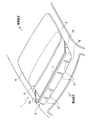
- the sunroof device 1 includes a roof panel 4 that opens and closes a substantially rectangular opening 3 formed in a fixed roof 2 of the vehicle body, and the roof panel 4 slides backward to open the opening 3.
- a deflector 5 protruding upward from the fixed roof 2 along the front edge of the opening 3 is provided.
- the deflector 5 includes a thin cloth member 6, and an upper holder 7 and a lower holder 8 that support the upper and lower sides of the thin cloth member 6, respectively.
- the thin cloth-like member 6 is composed of a fine mesh of a flexible fabric material.
- the upper edge and the lower edge of the thin cloth-like member 6 are formed in a bag shape when viewed from the side by sewing or the like, and the core rods 9 and 10 inserted into the respective bag portions are the upper holder 7 and the lower holder 8. It is inserted and fixed in each groove part.
- the upper holder 7 and the lower holder 8 are formed of, for example, a resin material.
- the upper holder 7 is formed along the front edge of the opening 3, and both ends are formed as differential arms 7A and 7A extending rearward.
- the rear end of the differential arm 7A is supported so as to be rotatable about a rotation axis O along the vehicle width direction.
- an elastic member (not shown) is attached to the differential arm 7A to urge the upper holder 7 around the rotation axis O in a direction in which the upper holder 7 always protrudes upward.
- the lower holder 8 shown in FIG. 2 is also formed along the front edge of the opening 3, and both ends extend slightly rearward.
- the lower holder 8 is fixed to the front frame 11.
- Below the side edges of the opening 3 are disposed side frames (not shown) that perform a slide guide function for the roof panel 4, a support function for the differential arm 7A, and a support function for the elastic member.
- the front frame 11 is formed as a long member in the vehicle width direction so as to connect the front ends of the both side frames, and is disposed below the front edge of the opening 3.
- the front frame 11 is formed of, for example, a resin material.
- the front frame 11 is formed by bending the front end portion 11A, which is inclined in a slightly forward-downward manner following the fixed roof 2, and bent downward from the rear end of the front end portion 11A in order from the front side in a side sectional view.
- a shape having The lower holder 8 is supported on a plurality of holder fixing protrusions 12 and 13 formed at intervals in the vehicle width direction in the front frame 11 and fixed on the first bottom portion 11B. That is, the lower side of the thin cloth-like member 6 is connected and fixed to the front frame 11 via the lower holder 8.
- a pressing shoe (not shown) provided on the lower surface of the roof panel 4 pushes down the differential arm 7A against the urging force of the elastic member, so that the upper holder 7 is moved downward.
- the thin cloth member 6 is folded and stored above the front frame 11.
- the upper holder 7 is displaced upward by the urging force of the elastic member, and the thin cloth member 6 is stretched and unfolded to rectify the traveling wind. And restrains airflow from entering the room.
- the deflector structure of the present invention includes a storage guiding member 14 that guides the folding operation of the thin cloth member 6.
- the storage guiding member 14 is a fixed portion between the front frame 11 and the thin cloth-like member 6, that is, a front first standing wall 15 standing rearward from the front frame 11 behind the lower holder 8 and a rear second second.
- the standing wall 16 and the upper holder 7 are configured to include a guide wall 17 formed along the upper rear surface of the stretched thin cloth member.
- the first standing wall 15 extends substantially along the vehicle width direction so as to be inclined slightly forward from the middle in the vehicle longitudinal direction at the second bottom portion 11C.
- the second standing wall 16 extends substantially along the vehicle width direction so as to be inclined slightly forward from the front end of the rear end portion 11D.
- the second standing wall 16 is formed slightly higher than the first standing wall 15. Both the first standing wall 15 and the second standing wall 16 are formed integrally with the front frame 11.
- the guide wall 17 is a plate-like wall formed integrally with the upper holder 7 and extends substantially along the vehicle width direction. As shown by a virtual line in FIG. 2, the thin cloth-like member 6 is disposed behind the second standing wall 16 when stretched, and as shown by a solid line, the first standing wall 15 and the second wall 16 are disposed when stored. It arrange
- the guide wall 17 is displaced about the rotation axis O, so that the guide wall 17 is displaced forward as it is lowered.
- the upper end of the guide wall 17 at the time of storage is located at substantially the same height as the upper end of the second standing wall 16.
- “Action” 3A shows a state in which the thin cloth-like member 6 is stretched and deployed, and the guide wall 17 is positioned behind the second standing wall 16.
- the thin cloth-like member 6 is stretched and stretched in an inclined manner so that the upper side is displaced rearward.
- the upper part of the thin cloth member 6 is stretched so as to be substantially parallel to the guide wall 17.
- the thin fabric member 6 has a first lower portion as shown in FIGS. 3 (b) and 3 (c).
- the upper end of the wall 15 is folded so as to cover the first standing wall 15.
- the guide wall 17 located behind the second standing wall 16 is displaced forward as it is displaced downward, as shown in FIG. In this case, the lower end of the guide wall 17 is given an opportunity to bend so as to protrude rearward.
- the guide wall 17 is positioned between the first standing wall 15 and the second standing wall 16, and the thin cloth member 6 is 1 It is stored in a folded state by the standing wall 15 and the guide wall 17. Since the second standing wall 16 exists, the thin cloth member 6 does not protrude to the rear side.
- the second standing wall 16 and a guide wall 17 formed along the upper rear surface of the thin cloth member 6 stretched and deployed in the upper holder 7, and the guide wall 17 is formed of the thin cloth member 6. If it is arranged behind the second upright wall 16 when deployed, and placed between the first upright wall 15 and the second upright wall 16 during storage, the thin cloth member 6 The folded shape can be stabilized. Therefore, it is not necessary to secure a large storage space for the thin cloth-like member 6 and the exposure of the thin cloth-like member 6 to the room can be prevented. Moreover, the opening dimension of the opening part 3 of the sunroof apparatus 1 can be enlarged by the part which can keep the storage space of the thin cloth-like member 6 small.
- the shape stabilizing member 21 is made of, for example, a rubber (rubber) member. As shown in FIG. 4, a plurality of vertical belt-shaped shape stabilizing members 21 are attached with an interval in the vehicle width direction. The presence of the shape stabilizing member 21 restricts the folding operation of the thin cloth-like member 6 made of a flexible fabric, so that the folding shape is stabilized and the variation in the folding shape of the thin cloth-like member 6 is further reduced. Is done.
Landscapes
- Engineering & Computer Science (AREA)
- Mechanical Engineering (AREA)
- Body Structure For Vehicles (AREA)
- Vehicle Interior And Exterior Ornaments, Soundproofing, And Insulation (AREA)
- Folding Of Thin Sheet-Like Materials, Special Discharging Devices, And Others (AREA)
Priority Applications (2)
| Application Number | Priority Date | Filing Date | Title |
|---|---|---|---|
| US15/316,798 US9758026B2 (en) | 2014-06-06 | 2015-04-08 | Deflector structure for sunroof device |
| CN201580022507.XA CN107428231B (zh) | 2014-06-06 | 2015-04-08 | 天窗装置的导向器构造 |
Applications Claiming Priority (2)
| Application Number | Priority Date | Filing Date | Title |
|---|---|---|---|
| JP2014117504A JP6022504B2 (ja) | 2014-06-06 | 2014-06-06 | サンルーフ装置のディフレクタ構造 |
| JP2014-117504 | 2014-06-06 |
Publications (1)
| Publication Number | Publication Date |
|---|---|
| WO2015186426A1 true WO2015186426A1 (ja) | 2015-12-10 |
Family
ID=54766507
Family Applications (1)
| Application Number | Title | Priority Date | Filing Date |
|---|---|---|---|
| PCT/JP2015/060966 Ceased WO2015186426A1 (ja) | 2014-06-06 | 2015-04-08 | サンルーフ装置のディフレクタ構造 |
Country Status (4)
| Country | Link |
|---|---|
| US (1) | US9758026B2 (enExample) |
| JP (1) | JP6022504B2 (enExample) |
| CN (1) | CN107428231B (enExample) |
| WO (1) | WO2015186426A1 (enExample) |
Families Citing this family (10)
| Publication number | Priority date | Publication date | Assignee | Title |
|---|---|---|---|---|
| CN106218377A (zh) * | 2016-08-24 | 2016-12-14 | 江苏德福来汽车部件有限公司 | 一种汽车天窗挡风网固定块 |
| US10569626B2 (en) | 2016-09-21 | 2020-02-25 | Yachiyo Industry Co., Ltd. | Deflector device for vehicle sunroof |
| DE102017109047B3 (de) | 2017-04-27 | 2018-09-06 | Macauto Industrial Co., Ltd. | Windabweiser für Fahrzeuge |
| CN107351661B (zh) * | 2017-08-01 | 2023-05-19 | 上海毓恬冠佳科技股份有限公司 | 一种汽车天窗挡风网定向折叠结构 |
| US10583725B1 (en) * | 2018-09-28 | 2020-03-10 | Nissan North America, Inc. | Vehicle wind deflector assembly |
| JP7183903B2 (ja) * | 2019-03-26 | 2022-12-06 | 豊田合成株式会社 | ルーフウェザストリップ |
| DE102019126860A1 (de) * | 2019-10-07 | 2021-04-08 | Webasto SE | Deckel zum Verschließen einer Öffnung in einer Fahrzeugkarosserie |
| JP7434989B2 (ja) * | 2020-02-13 | 2024-02-21 | 株式会社アイシン | 車両用サンルーフユニット |
| CN112223994B (zh) * | 2020-09-09 | 2024-03-19 | 一汽奔腾轿车有限公司 | 一种天窗导风网防夹结构 |
| KR102634316B1 (ko) * | 2021-08-31 | 2024-02-05 | 한정현 | 출혈량 측정이 가능한 의료용 시스템 |
Citations (5)
| Publication number | Priority date | Publication date | Assignee | Title |
|---|---|---|---|---|
| JPH02100818U (enExample) * | 1989-01-31 | 1990-08-10 | ||
| US20030038512A1 (en) * | 2001-08-01 | 2003-02-27 | Webasto Vehicle Systems International Gmbh | Wind deflector for motor vehicle roof |
| DE102008006344B3 (de) * | 2008-01-28 | 2009-04-09 | Webasto Ag | Seitliche Deckelelementblenden |
| US20100313486A1 (en) * | 2009-06-10 | 2010-12-16 | Akihiko Kuribayashi | Seal mechanical holder for sunroof assembly |
| DE102011116109A1 (de) * | 2011-10-15 | 2013-04-18 | Volkswagen Aktiengesellschaft | Windabweiser für ein Dach oder ein Dachmodul eines Fahrzeugs, Dach, Dachmodul oder Fahrzeug mit einem derartigen Windabweiser |
Family Cites Families (4)
| Publication number | Priority date | Publication date | Assignee | Title |
|---|---|---|---|---|
| DE602005018223D1 (de) * | 2005-10-31 | 2010-01-21 | Inalfa Roof Sys Group Bv | Schiebedach für ein Fahrzeug und Windabweiser |
| DE102010048964B4 (de) | 2010-10-20 | 2015-08-06 | Webasto SE | Schiebedachwindabweiser und dessen Herstellung |
| CN202389172U (zh) * | 2011-12-14 | 2012-08-22 | 恩坦华汽车系统(上海)有限公司 | 汽车天窗导风板 |
| JP6035802B2 (ja) * | 2012-03-21 | 2016-11-30 | アイシン精機株式会社 | 車両用デフレクタ装置 |
-
2014
- 2014-06-06 JP JP2014117504A patent/JP6022504B2/ja active Active
-
2015
- 2015-04-08 US US15/316,798 patent/US9758026B2/en active Active
- 2015-04-08 CN CN201580022507.XA patent/CN107428231B/zh active Active
- 2015-04-08 WO PCT/JP2015/060966 patent/WO2015186426A1/ja not_active Ceased
Patent Citations (5)
| Publication number | Priority date | Publication date | Assignee | Title |
|---|---|---|---|---|
| JPH02100818U (enExample) * | 1989-01-31 | 1990-08-10 | ||
| US20030038512A1 (en) * | 2001-08-01 | 2003-02-27 | Webasto Vehicle Systems International Gmbh | Wind deflector for motor vehicle roof |
| DE102008006344B3 (de) * | 2008-01-28 | 2009-04-09 | Webasto Ag | Seitliche Deckelelementblenden |
| US20100313486A1 (en) * | 2009-06-10 | 2010-12-16 | Akihiko Kuribayashi | Seal mechanical holder for sunroof assembly |
| DE102011116109A1 (de) * | 2011-10-15 | 2013-04-18 | Volkswagen Aktiengesellschaft | Windabweiser für ein Dach oder ein Dachmodul eines Fahrzeugs, Dach, Dachmodul oder Fahrzeug mit einem derartigen Windabweiser |
Also Published As
| Publication number | Publication date |
|---|---|
| CN107428231A (zh) | 2017-12-01 |
| JP2015229453A (ja) | 2015-12-21 |
| US9758026B2 (en) | 2017-09-12 |
| JP6022504B2 (ja) | 2016-11-09 |
| US20170182870A1 (en) | 2017-06-29 |
| CN107428231B (zh) | 2019-12-20 |
Similar Documents
| Publication | Publication Date | Title |
|---|---|---|
| JP6022504B2 (ja) | サンルーフ装置のディフレクタ構造 | |
| JP2015229453A5 (enExample) | ||
| JP6154078B2 (ja) | サンルーフ装置のディフレクタ構造 | |
| JP2015229454A (ja) | サンルーフ装置のディフレクタ構造 | |
| CN106394353B (zh) | 交通工具座椅 | |
| US6923236B2 (en) | Sector curtain | |
| JP6891608B2 (ja) | サンシェード装置 | |
| US10406901B2 (en) | Wind deflector having a fastening system for an unfoldable deflector element | |
| CN207449597U (zh) | 导流器装置 | |
| JP6154079B2 (ja) | サンルーフ装置のディフレクタ構造 | |
| BR102014022757A2 (pt) | defletor de vento | |
| JP4434910B2 (ja) | 車体後部の遮光構造 | |
| US1591567A (en) | Lens hood | |
| US1535056A (en) | Educational appliance | |
| TWM457661U (zh) | 具有滑蓋的遮陽簾 | |
| JP6112958B2 (ja) | ロールシェード装置 | |
| JP6279196B1 (ja) | 車両用サンルーフのデフレクタ装置 | |
| US576991A (en) | boviefi | |
| CN210370131U (zh) | 一种侧拉帐篷 | |
| KR101509324B1 (ko) | 폴딩 헤드레스트의 후방 차폐용 가림막 | |
| JP5287449B2 (ja) | サンシェード装置 | |
| JP2020006933A (ja) | サンルーフ装置 | |
| JP6055308B2 (ja) | オーニング装置 | |
| US1405057A (en) | Window attachment | |
| JP6453270B2 (ja) | 収納ケース |
Legal Events
| Date | Code | Title | Description |
|---|---|---|---|
| 121 | Ep: the epo has been informed by wipo that ep was designated in this application |
Ref document number: 15803462 Country of ref document: EP Kind code of ref document: A1 |
|
| NENP | Non-entry into the national phase |
Ref country code: DE |
|
| WWE | Wipo information: entry into national phase |
Ref document number: 15316798 Country of ref document: US |
|
| 122 | Ep: pct application non-entry in european phase |
Ref document number: 15803462 Country of ref document: EP Kind code of ref document: A1 |