WO2015182727A1 - ガスタービンエンジンの燃焼装置 - Google Patents
ガスタービンエンジンの燃焼装置 Download PDFInfo
- Publication number
- WO2015182727A1 WO2015182727A1 PCT/JP2015/065477 JP2015065477W WO2015182727A1 WO 2015182727 A1 WO2015182727 A1 WO 2015182727A1 JP 2015065477 W JP2015065477 W JP 2015065477W WO 2015182727 A1 WO2015182727 A1 WO 2015182727A1
- Authority
- WO
- WIPO (PCT)
- Prior art keywords
- fuel
- combustion
- air
- fuel injection
- annular
- Prior art date
Links
Images


Classifications
-
- F—MECHANICAL ENGINEERING; LIGHTING; HEATING; WEAPONS; BLASTING
- F23—COMBUSTION APPARATUS; COMBUSTION PROCESSES
- F23R—GENERATING COMBUSTION PRODUCTS OF HIGH PRESSURE OR HIGH VELOCITY, e.g. GAS-TURBINE COMBUSTION CHAMBERS
- F23R3/00—Continuous combustion chambers using liquid or gaseous fuel
- F23R3/28—Continuous combustion chambers using liquid or gaseous fuel characterised by the fuel supply
- F23R3/286—Continuous combustion chambers using liquid or gaseous fuel characterised by the fuel supply having fuel-air premixing devices
-
- F—MECHANICAL ENGINEERING; LIGHTING; HEATING; WEAPONS; BLASTING
- F23—COMBUSTION APPARATUS; COMBUSTION PROCESSES
- F23R—GENERATING COMBUSTION PRODUCTS OF HIGH PRESSURE OR HIGH VELOCITY, e.g. GAS-TURBINE COMBUSTION CHAMBERS
- F23R3/00—Continuous combustion chambers using liquid or gaseous fuel
- F23R3/28—Continuous combustion chambers using liquid or gaseous fuel characterised by the fuel supply
- F23R3/34—Feeding into different combustion zones
-
- F—MECHANICAL ENGINEERING; LIGHTING; HEATING; WEAPONS; BLASTING
- F02—COMBUSTION ENGINES; HOT-GAS OR COMBUSTION-PRODUCT ENGINE PLANTS
- F02C—GAS-TURBINE PLANTS; AIR INTAKES FOR JET-PROPULSION PLANTS; CONTROLLING FUEL SUPPLY IN AIR-BREATHING JET-PROPULSION PLANTS
- F02C7/00—Features, components parts, details or accessories, not provided for in, or of interest apart form groups F02C1/00 - F02C6/00; Air intakes for jet-propulsion plants
- F02C7/22—Fuel supply systems
- F02C7/232—Fuel valves; Draining valves or systems
-
- F—MECHANICAL ENGINEERING; LIGHTING; HEATING; WEAPONS; BLASTING
- F23—COMBUSTION APPARATUS; COMBUSTION PROCESSES
- F23R—GENERATING COMBUSTION PRODUCTS OF HIGH PRESSURE OR HIGH VELOCITY, e.g. GAS-TURBINE COMBUSTION CHAMBERS
- F23R3/00—Continuous combustion chambers using liquid or gaseous fuel
- F23R3/002—Wall structures
-
- F—MECHANICAL ENGINEERING; LIGHTING; HEATING; WEAPONS; BLASTING
- F23—COMBUSTION APPARATUS; COMBUSTION PROCESSES
- F23R—GENERATING COMBUSTION PRODUCTS OF HIGH PRESSURE OR HIGH VELOCITY, e.g. GAS-TURBINE COMBUSTION CHAMBERS
- F23R3/00—Continuous combustion chambers using liquid or gaseous fuel
- F23R3/02—Continuous combustion chambers using liquid or gaseous fuel characterised by the air-flow or gas-flow configuration
- F23R3/16—Continuous combustion chambers using liquid or gaseous fuel characterised by the air-flow or gas-flow configuration with devices inside the flame tube or the combustion chamber to influence the air or gas flow
-
- F—MECHANICAL ENGINEERING; LIGHTING; HEATING; WEAPONS; BLASTING
- F23—COMBUSTION APPARATUS; COMBUSTION PROCESSES
- F23R—GENERATING COMBUSTION PRODUCTS OF HIGH PRESSURE OR HIGH VELOCITY, e.g. GAS-TURBINE COMBUSTION CHAMBERS
- F23R3/00—Continuous combustion chambers using liquid or gaseous fuel
- F23R3/28—Continuous combustion chambers using liquid or gaseous fuel characterised by the fuel supply
- F23R3/283—Attaching or cooling of fuel injecting means including supports for fuel injectors, stems, or lances
-
- F—MECHANICAL ENGINEERING; LIGHTING; HEATING; WEAPONS; BLASTING
- F23—COMBUSTION APPARATUS; COMBUSTION PROCESSES
- F23R—GENERATING COMBUSTION PRODUCTS OF HIGH PRESSURE OR HIGH VELOCITY, e.g. GAS-TURBINE COMBUSTION CHAMBERS
- F23R3/00—Continuous combustion chambers using liquid or gaseous fuel
- F23R3/28—Continuous combustion chambers using liquid or gaseous fuel characterised by the fuel supply
- F23R3/30—Continuous combustion chambers using liquid or gaseous fuel characterised by the fuel supply comprising fuel prevapourising devices
- F23R3/32—Continuous combustion chambers using liquid or gaseous fuel characterised by the fuel supply comprising fuel prevapourising devices being tubular
-
- F—MECHANICAL ENGINEERING; LIGHTING; HEATING; WEAPONS; BLASTING
- F23—COMBUSTION APPARATUS; COMBUSTION PROCESSES
- F23C—METHODS OR APPARATUS FOR COMBUSTION USING FLUID FUEL OR SOLID FUEL SUSPENDED IN A CARRIER GAS OR AIR
- F23C2900/00—Special features of, or arrangements for combustion apparatus using fluid fuels or solid fuels suspended in air; Combustion processes therefor
- F23C2900/9901—Combustion process using hydrogen, hydrogen peroxide water or brown gas as fuel
-
- F—MECHANICAL ENGINEERING; LIGHTING; HEATING; WEAPONS; BLASTING
- F23—COMBUSTION APPARATUS; COMBUSTION PROCESSES
- F23D—BURNERS
- F23D2209/00—Safety arrangements
- F23D2209/20—Flame lift-off / stability
-
- F—MECHANICAL ENGINEERING; LIGHTING; HEATING; WEAPONS; BLASTING
- F23—COMBUSTION APPARATUS; COMBUSTION PROCESSES
- F23R—GENERATING COMBUSTION PRODUCTS OF HIGH PRESSURE OR HIGH VELOCITY, e.g. GAS-TURBINE COMBUSTION CHAMBERS
- F23R2900/00—Special features of, or arrangements for continuous combustion chambers; Combustion processes therefor
- F23R2900/03044—Impingement cooled combustion chamber walls or subassemblies
-
- Y—GENERAL TAGGING OF NEW TECHNOLOGICAL DEVELOPMENTS; GENERAL TAGGING OF CROSS-SECTIONAL TECHNOLOGIES SPANNING OVER SEVERAL SECTIONS OF THE IPC; TECHNICAL SUBJECTS COVERED BY FORMER USPC CROSS-REFERENCE ART COLLECTIONS [XRACs] AND DIGESTS
- Y02—TECHNOLOGIES OR APPLICATIONS FOR MITIGATION OR ADAPTATION AGAINST CLIMATE CHANGE
- Y02T—CLIMATE CHANGE MITIGATION TECHNOLOGIES RELATED TO TRANSPORTATION
- Y02T50/00—Aeronautics or air transport
- Y02T50/60—Efficient propulsion technologies, e.g. for aircraft
- Y02T50/678—Aviation using fuels of non-fossil origin
Definitions
- the present invention relates to a combustion apparatus used for a gas turbine engine.
- Gas turbine engines have strict environmental standards regarding the composition of exhaust gas emitted by combustion, considering environmental conservation, and it is required to reduce harmful substances such as nitrogen oxides (hereinafter referred to as NOx). It has been. Therefore, in recent years, a combustion method that adopts a premixed combustion method that effectively reduces the amount of NOx generated, for example, a combined combustion method that combines a lean premixed combustion method and a diffusion combustion method has been proposed (Patent Literature). 1).
- the flame generated in the combustion chamber is maintained because a strong swirl flow is generated in the combustion chamber to form a backflow region in order to maintain the combustion with the lean fuel. Tends to cause a flashback phenomenon that propagates in the premixing passage.
- gas turbine engines that use hydrogen as a fuel have been proposed. However, in a gas turbine engine that uses a highly reactive fuel containing hydrogen, a flashback phenomenon is particularly likely to occur.
- an object of the present invention is to solve the above-described problems, and a gas turbine that can prevent local high-temperature combustion and suppress generation of NOx, and can prevent a flashback phenomenon and stably hold a flame. It is to provide an engine combustion apparatus.
- a combustion apparatus includes a combustion cylinder that forms a combustion chamber inside, a fuel injection member that is provided at the top of the combustion cylinder and includes a plurality of annular portions for fuel injection, and An air guide member including a plurality of annular portions for combustion air for guiding combustion air, wherein the annular portions for fuel injection and the annular portions for combustion air are alternately arranged concentrically, and fuel is supplied to the combustion chamber; And a fuel injector for injecting air, and a reburning burner disposed in the downstream area of the combustion chamber and on the peripheral wall of the combustion cylinder, the annular portion for fuel injection is opened in the radial direction thereof
- the combustion air annular portion has a plurality of air guide grooves that open in the axial center direction and guide air to the fuel injected from the fuel injection holes.
- the reheating burner has a premixing chamber for mixing and stirring fuel and air, and is configured to inject premixed gas generated in the premixing chamber into the combustion chamber. It is preferable that According to this configuration, by providing a premixing type reburning burner in a region where the combustion reaction has progressed in the downstream region of the combustion chamber, it is possible to further reduce NOx while suppressing the occurrence of a backfire phenomenon in the reburning burner. Can be suppressed.
- an air rectification mechanism is provided upstream of the fuel injector and rectifies air supplied to the air guide member. According to this configuration, since a uniform air flow is supplied to the combustion injection unit, the generation of NOx is suppressed by further uniforming the combustion, and the flashback phenomenon can be prevented more reliably.
- the rectifying protrusion member includes a support part and a protrusion part protruding from the support part into the combustion chamber, and the rectifying protrusion member is formed in the support part to allow air to flow inside the rectifying protrusion member. It is preferable to have a cooling air introduction hole for introducing the air into the combustion chamber, and a cooling air exhaust hole formed in the protruding portion for discharging the air introduced into the rectifying protrusion member into the combustion chamber. According to the said structure, a protrusion can be cooled by convection cooling from the inside using a part of combustion air.
- the annular portion for fuel injection is formed in a hollow shape, and the hollow space in the annular portion for fuel injection forms an annular fuel flow passage for circulating fuel in the circumferential direction.
- the portion of the annular portion for fuel injection that faces the combustion chamber is exposed to a high temperature due to the flame in the combustion chamber.
- an annular fuel flow passage through which fuel flows is formed inside the annular portion for fuel injection. Therefore, the portion exposed to the high temperature is efficiently cooled by the fuel flowing through the fuel flow passage.
- the annular portion for fuel injection is located on the combustion chamber side, is located on the opposite side to the combustion chamber, and a first fuel flow passage communicating with the fuel injection hole, A second fuel flow path to which fuel injected from the fuel injection hole is supplied; and an injection nozzle for injecting fuel in the second fuel flow path to the wall surface of the first fuel flow path on the combustion chamber side. It is preferable to have.
- the wall facing the combustion chamber of the annular part for fuel injection can be cooled from the inside by impingement cooling using fuel.
- a fuel supply mother pipe having a multi-tube structure for supplying fuel to the fuel injection member is provided, and the fuel supply mother pipe is a first annular of the plurality of fuel injection annular portions. It is preferable to have a first supply passage for supplying fuel to the group and a second supply passage for supplying fuel to the second annular group of the plurality of annular portions for fuel injection.
- the fuel injection member can be divided into a fuel injection annular portion that supplies fuel and a fuel injection annular portion that does not supply fuel. Corresponding operation (staging combustion) becomes possible.
- FIG. 1 is a block diagram showing a schematic configuration of a gas turbine engine to which a combustion apparatus according to an embodiment of the present invention is applied. It is sectional drawing which shows the combustion apparatus which concerns on one Embodiment of this invention. It is sectional drawing which shows the combustion apparatus which concerns on one Embodiment of this invention. It is a front view which shows the fuel injector used for the combustion apparatus of FIG.
- FIG. 5A It is a front view which expands and shows a part of fuel injector used for the combustion apparatus of FIG. It is a front view which shows the modification of the fuel injector of FIG. 5A. It is a perspective view which shows an example of the air baffle plate used for the combustion apparatus of FIG. It is a perspective view which shows the other example of the air baffle plate used for the combustion apparatus of FIG. It is a perspective view which shows the other example of the air baffle plate used for the combustion apparatus of FIG. It is a perspective view which shows the other example of the air baffle plate used for the combustion apparatus of FIG. It is a perspective view which shows the modification of the air rectification mechanism of the combustion apparatus of FIG. FIG.
- FIG. 10 is a perspective view showing another modification of the air rectifying mechanism of the combustion device of FIG. 2. It is a longitudinal cross-sectional view which shows the fuel injector used for the combustion apparatus of FIG. It is a longitudinal cross-sectional view which shows the modification of the fuel injector used for the combustion apparatus of FIG. It is a longitudinal cross-sectional view which shows the internal structure of the baffle protrusion member used for the combustion apparatus of FIG. It is sectional drawing which shows the combustion apparatus which concerns on one Embodiment which applied this invention to the annular type combustion apparatus. It is a partially broken perspective view of the combustion apparatus of FIG. It is sectional drawing which shows the combustion apparatus which concerns on other embodiment which applied this invention to the annular type combustion apparatus.
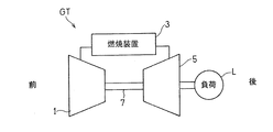
- FIG. 1 shows a schematic configuration of a gas turbine engine (hereinafter simply referred to as a gas turbine) GT to which a combustion apparatus according to an embodiment of the present invention is applied.
- a gas turbine engine hereinafter simply referred to as a gas turbine
- the introduced air is compressed by the compressor 1 and guided to the combustion device 3
- fuel is injected into the combustion device 3 and burned together with the air
- the turbine 5 is driven by the obtained high-temperature and high-pressure combustion gas.
- the turbine 5 is connected to the compressor 1 via the rotary shaft 7, and the compressor 1 is driven by the turbine 5.
- a load L such as an aircraft rotor or a generator is driven by the output of the gas turbine GT.
- hydrogen gas is used as the fuel injected into the combustion device 3.
- the compressor 1 side in the axial direction of the gas turbine GT is referred to as “front side”
- the turbine 5 side is referred to as “rear side”.
- FIG. 2 is a partially broken perspective view showing the combustion device 3.
- the combustion apparatus 3 is a can-type combustion apparatus that is arranged in a ring shape around the axis of the gas turbine GT.
- the combustion device 3 includes a combustion cylinder 13 that forms a combustion chamber 11 inside, and a fuel injector 15 that is attached to the top 13 a of the combustion cylinder 13 and injects fuel and air into the combustion chamber 11.
- a flame is formed in the combustion chamber 11 by igniting the fuel and air injected from the fuel injector 15 with a spark plug P provided in the combustion cylinder 13.
- the combustion cylinder 13 and the fuel injector 15 are accommodated concentrically in a substantially cylindrical housing H that is an outer cylinder of the combustion apparatus 3.
- An end cover 17 is fixed to the front end of the housing H with a bolt 19.
- the top 13 a of the combustion cylinder 13 is attached to the housing H by connecting and fixing a support cylinder 21 extending in a cylindrical shape from the combustion cylinder 13 to the end cover 17 with a bolt or the like.
- the combustion device 3 is configured as a reverse flow type in which the flow directions of the air A and the combustion gas G are opposite. That is, the combustion device 3 has an air introduction passage 25 formed between the housing H, the combustion cylinder 13 and the support cylinder 21, and this air introduction passage 25 is compressed by the compressor 1 (FIG. 1). The conducted air A is guided in a direction opposite to the flow direction of the combustion gas G in the combustion chamber 11.
- the combustion device 3 may be an axial flow type in which the flow directions of the air A and the combustion gas G are the same.
- a plurality of air introduction holes 27 are arranged in the circumferential direction at the front end portion of the peripheral wall of the support cylinder 21.
- the air A sent through the air introduction passage 25 is introduced into the air supply passage 29 formed inside the support tube 21 through the air introduction hole 27.
- the air A introduced into the air supply passage 29 is sent backward, that is, in the direction of the fuel injector 15.
- a fuel supply mother pipe 31 extending along the axis C of the combustion device 3 is provided at the center of the air supply passage 29.
- the fuel F is supplied from the fuel supply pipe 31 to the fuel injection annular portion 33 of the fuel injection member 34 described later.
- the configurations of the air supply passage 29 and the fuel supply mother pipe 31 will be described in detail later.
- the combustion apparatus 3 includes a premixed reheating burner 10 disposed in the downstream area of the combustion chamber 11 and on the peripheral wall of the combustion cylinder 13. A plurality (for example, four) of burner burners 10 are provided at equal intervals in the circumferential direction.
- the air A sent from the compressor 1 (FIG. 1) through the air introduction passage 25 and the fuel F sent from the fuel supply system (reheating fuel supply passage 32) are sent to the reheating burner 10. be introduced.
- the reheating burner 10 is a premixing type and has a premixing chamber 10a for mixing and stirring the air A and the fuel F. As shown in FIG.
- the air A is introduced into the premixing chamber 10 a from the side peripheral surface of the reheating burner 10, and the fuel F is supplied from the fuel supply system via the reconditioning adjustment valve 72.
- the fuel injection hole 10c may be provided as a fuel injection nozzle whose tip protrudes into the premixing chamber 10a.
- the reheating burner 10 is operated in a state in which combustion by the fuel injector 15 that is a main burner is almost completed and high-temperature combustion gas G is generated, so that the reburning burner 10 is injected into the downstream region of the combustion chamber 11.
- the premixed gas M is burned stably while suppressing generation of NOx by the high-temperature combustion gas G.
- the reheating burner 10 according to the present embodiment does not require a swirl flow generating mechanism or the like (flame holding mechanism) for forming a backflow region for flame holding, and therefore has high resistance to backfire. Therefore, even hydrogen, which is normally difficult to use as premixed combustion, can be used as a fuel for the reheating burner 10 without fear of backfire.
- the reheating burner 10 is not limited to the premixing type, but may be a diffusion combustion type.
- the fuel injector 15 includes a fuel injection member 34 having a plurality of fuel injection annular portions 33 and an air guide member 36 having a plurality of combustion air annular portions 35.
- the four fuel injection annular portions 33 having different diameters are arranged concentrically with each other and with the combustion device 3 (FIG. 2).
- five combustion air annular portions 35 having different diameters are arranged concentrically with each other and with the combustion device 3 (FIG. 2).
- the annular portions for fuel injection 33 and the annular portions for combustion air 35 are alternately arranged with the same central axis. That is, the annular portion for fuel injection 33 and the annular portion for combustion air 35 are alternately arranged concentrically.
- the fuel injector 15 has four fuel injection annular portions 33 and five combustion air annular portions 35.
- the number of these can be changed as appropriate, for example, 3 One annular portion 33 for fuel injection and four annular portions 35 for combustion air may be used.
- the four fuel injection annular portions 33 and the five combustion air annular portions 35 are provided at the same axial position (FIG. 3).
- the axial positions of the four fuel injection annular portions 33 and the five combustion air annular portions 35 may be shifted from each other.
- the four fuel injection annular portions 33 may be arranged so that the axial direction positions of the four fuel injection annular portions 33 are sequentially shifted back and forth. You may arrange
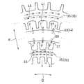
- the fuel injection annular portion 33 of the fuel injection member 34 is provided with a plurality of fuel injection holes 39 opened in the radial direction R in the circumferential direction Q. Fuel F is injected from each fuel injection hole 39.
- the fuel injection annular portion 33 of the fuel injection member 34 has a substantially rectangular cross-sectional outer shape, and the rear wall 33 a facing the combustion chamber 11 is perpendicular to the axis C direction. It is arranged to become.
- the fuel injection holes 39 are provided on both the outer diameter side and the inner diameter side of the fuel injection annular portion 33 of the fuel injection member 34.
- the fuel injection hole 39 is provided in each of the outer peripheral wall and the inner peripheral wall of the fuel injection annular portion 33 as a through hole that penetrates the outer peripheral wall and the inner peripheral wall in the radial direction R.
- the fuel injection holes 39 may be provided only on either the outer diameter side or the inner diameter side of the fuel injection member 34.
- the fuel injection hole 39 may be inclined in the range from ⁇ 10 ° to + 80 ° in the axis C direction with respect to the radial direction R.
- the inclination angle when the fuel injection hole 39 is inclined upstream of the radial direction R in the axial center C direction is a negative inclination angle
- the fuel injection hole is downstream of the radial direction R in the axial center C direction.
- the inclination angle when 39 is inclined is defined as a positive inclination angle.
- the air guide member 36 guides the air A to the fuel F injected from the fuel injection hole 39 of the fuel injection member 34. More specifically, the air guide member 36 guides the air A in the direction of the axis C from the upstream side of the air supply passage 29 with respect to the fuel F.
- the air guide member 36 has a plurality of annular portions 35 for combustion air in the shape of an annular plate.
- the fuel injection annular portion 33 of the fuel injection member 34 and the combustion air annular portion 35 of the air guide member 36 are alternately arranged with the same central axis. As shown in FIG.
- an air guide groove 41 that is recessed in the radial direction is formed at a circumferential position corresponding to each fuel injection hole 39 of the fuel injection member 34.
- an air guide groove that is recessed radially outwardly on the inner diameter side of the combustion air annular portion 35 of the air guide member 36 located on the radially outer side of the fuel injection annular portion 33 of the fuel injection member 34. 41 is formed, and an air guide groove 41 that is recessed radially inward is formed on the outer diameter side of the combustion air annular portion 35 that is located on the radially inner side of the fuel injection annular portion 33.
- the fuel injector 15 includes a fuel injection member 34 having four annular portions 33 for fuel injection and an air guide member 36 having five annular portions 35 for combustion air.
- the combustion air annular portion 35 disposed on the outer peripheral side of the outermost peripheral fuel injection annular portion 33 and the three combustion air annular portions disposed between each of the four fuel injection annular portions 33.
- An annular portion 35 for combustion air disposed on the inner peripheral side of the portion 35 and the innermost fuel injection annular portion 33 is provided.
- the outer periphery of the combustion air annular portion 35 disposed on the outermost periphery is covered with an annular support ring member 43.
- the fuel injector 15 is supported by the combustion cylinder 13 by connecting the support ring member 43 to the combustion cylinder 13.
- the air guide member 36 is disposed on the front side of the fuel injection hole 39 of the fuel injection member 34, that is, on the upstream side in the air A flow direction. In this way, by providing the air guide member 36 so as to guide the air A in the direction of the axis C from the upstream with respect to the fuel F injected from each fuel injection hole 39, the fuel F and the air A are almost mutually connected.
- the fuel F and the air A can be uniformly mixed outside the fuel injector 15.
- a plurality of cooling holes 45 may be provided in each combustion air annular portion 35 of the air guide member 36.
- the plurality of cooling holes 45 are arranged at equal intervals in the circumferential direction of the annular portion 35 for combustion air.
- the cooling hole 45 is formed as a through hole having a substantially circular cross section that penetrates the combustion air annular portion 35 from the front side to the rear side.
- each cooling hole 45 is formed to extend in the circumferential direction in the combustion air annular portion 35 while being inclined. Therefore, the shape of the opening of the cooling hole 45 on the surface of the annular portion 35 for combustion air is an elliptical shape that is long in the circumferential direction.
- the cooling hole 45 when the cooling hole 45 is provided in the combustion air annular portion 35, the air A flowing through the air supply passage 29 (FIG. 3) passes through the cooling hole 45, and then the combustion air annular portion 35. It blows off to the combustion chamber side surface, forms a film layer of air along the circumferential direction, and this surface is effusion cooled.
- the cooling hole 45 is preferably inclined in the circumferential direction, but the inclination direction is not limited to this. Further, the cooling hole 45 does not necessarily have to be inclined, and may be a through hole extending in parallel with the axial direction.
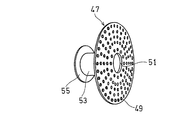
- the air supply passage 29 has an air rectifying plate 47 as an air rectifying mechanism that rectifies the air A introduced into the air supply passage 29 from the air introduction hole 27 into a uniform flow toward the air guide member 36.
- the air rectifying plate 47 is a disk-shaped member and has a plurality of through holes 49 penetrating in the axial direction.
- the air rectifying plate 47 has an outer diameter that matches the inner diameter of the support cylinder 21 of FIG. 3 and a fitting hole 51 having an inner diameter that matches the outer diameter of the fuel supply mother pipe 31 at the center.
- the air rectifying plate 47 is connected and fixed to the end cover 17 by a rectifying plate bolt 57 via a flange 55 provided at the front end of the fitting portion 53.
- the air rectifying plate 47 has a plurality of circular through holes 49 having the same diameter. More specifically, the plurality of through-holes 49 are formed by arranging rows of annular through-holes 49 arranged at equal intervals along the circumferential direction at the same radial position of the air rectifying plate 47 at equal intervals in the radial direction. It is arranged in a state where a plurality of rows are provided. That is, the air rectifying plate 47 has a row of annular through holes 49 arranged at equal intervals on the same circumference, and a plurality of the rows are provided with the same center.
- FIG. 6A shows an air rectifying mechanism including the air rectifying plate 47, the fitting portion 53, and the flange 55.
- the shape, number, and arrangement of the plurality of through holes 49 in the air rectifying plate 47 are not limited to the mode of FIG. 6A and may be set as appropriate.
- the inner circumferential edge and the outer circumferential edge of the air rectifying plate 47 are provided with a row of a large number of circular through-holes 49 having the same diameter, and intermediate between the inner circumferential edge and the outer circumferential edge.
- a row of circular through holes 49 having a larger diameter may be provided in the part.
- a row of a large number of circular through holes 49 having the same diameter is provided on the inner peripheral edge of the air rectifying plate 47, and the major axis direction is the radial direction of the air rectifying plate 47 on the outer peripheral side.
- a row of oval through holes 49 may be provided.
- only a row of oval through holes 49 whose major axis direction coincides with the radial direction of the air rectifying plate 47 may be provided.
- the ratio of the total area of all the through holes 49 to the entire area of the air rectifying plate 47 (opening ratio) Considering the balance of pressure loss, it is preferably in the range of 20 to 50%, more preferably in the range of 30 to 40%.
- FIG. 7A shows a flow straightening duct 61a extending from the upstream side of the air introduction hole 27 to the fuel injector 15 so as to reduce the diameter toward the downstream side, and a downstream side of the air introduction hole 27 to the fuel injector 15.
- a rectifying duct 61 having a rectifying duct 61b extending so as to increase in diameter toward the downstream side is shown.
- FIG. 7B shows a flow straightening duct 61a extending from the upstream side of the air introduction hole 27 to the fuel injector 15 so as to reduce the diameter toward the downstream side, and from the center position of the air introduction hole 27 to the fuel injector 15.
- a rectifying duct 61c that extends toward the downstream side, and a rectifying duct 61d that extends from the downstream side of the air introduction hole 27 to the fuel injector 15 so that the diameter decreases toward the downstream side;
- the rectifying duct 61 having By providing the air rectifying plate 47 and the rectifying duct 61 as the air rectifying mechanism, a uniform air flow is supplied to the fuel injector 15, so that the generation of NOx is suppressed by the uniform combustion and the flashback is ensured. The phenomenon can be prevented.
- the combustion device 3 is provided with a rectifying protrusion member 63 that is located on the axis C thereof and that protrudes toward the combustion chamber 11 through the fuel injector 15.
- the rectifying projection member 63 is located in the air supply passage 29 and includes a support portion 63 a having a cylindrical shape and a protruding portion 63 b located in the combustion chamber 11.
- the rectifying protrusion member 63 is attached to the fuel injector 15, but may be attached to the fuel supply main pipe 31. In any case, the front end (end on the fuel supply mother pipe 31 side) of the support portion 63 a of the rectifying protrusion member 63 is located upstream of the fuel injector 15.
- the protruding portion 63b has a substantially hemispherical tip.
- the rectifying protrusion member 63 may be omitted, by providing the rectifying protrusion member 63, the fuel injection annular portion 33 located on the radially inner side of the fuel injector 15 in the vicinity of the position of the axis C in the combustion chamber 11. The flame formed by the fuel injected from the air and the air supplied from the combustion air annular portion 35 is stably held.
- the fuel injection member 34, the air guide member 36, the support ring member 43, and the rectifying protrusion member 63 constituting the fuel injector 15 may be integrally formed. You may connect mutually by inserting a pin in a direction.
- the combustion device 3 of the present embodiment has a plurality of fuel supply paths that can supply the fuel F independently to each fuel injection annular portion 33 of the fuel injection member 34.
- the fuel supply main pipe 31 and each fuel injection annular portion 33 are connected by a plurality of branch fuel supply pipes 66 that branch independently from each other.
- the fuel supply mother pipe 31 has a plurality of (two in the illustrated example) cylindrical pipes, that is, an inner first fuel supply pipe 64 and a second fuel supply pipe 65 arranged outside thereof concentrically. It has a multi-tube structure (double tube structure).
- An inner space of the first fuel supply pipe 64 forms a first fuel supply path 67, and a space between the first fuel supply pipe 64 and the second fuel supply pipe 65 forms a second fuel supply path 69. is doing.
- the fuel F introduced from the outside into the fuel supply passages 67 and 69 in the fuel supply pipe 31 passes through the fuel supply passages formed in the branch fuel supply pipes 66 to the fuel injection annular portions 33. Supplied.
- the fuel F that has passed through the first fuel supply path 67 passes through the two branched fuel supply pipes 66 connected to the first fuel supply pipe 64, and is out of the plurality of fuel injection annular portions 33.
- the fuel F supplied to two fuel injection annular portions 33 (hereinafter referred to as “first annular portion group”) disposed on the inner diameter side and passed through the second fuel supply passage 69 is supplied to the second fuel supply pipe 65.
- Two fuel injection annular portions 33 (hereinafter referred to as “second annular portion group”) arranged on the outer diameter side of the plurality of fuel injection annular portions 33 via two branch fuel supply pipes 66 connected to ")".
- the first fuel supply passage 67 has an upstream portion 67a extending outside the housing H, and the second fuel supply passage 69 and an upstream portion 69a extending outside the housing H, respectively, to adjust the fuel flow rate.
- An adjustable control valve 71 is provided.
- the flow rate of the fuel F supplied to each annular portion group of the fuel injection annular portion 33 can be controlled independently by adjusting the opening degree of the control valve 71 of each fuel supply path 67, 69.
- the number of the fuel injection annular portions 33 constituting the annular portion group serving as a unit to which the fuel F is independently supplied is not limited to the above example.
- one annular portion for fuel injection 33 may constitute one annular portion group (a total of four annular portion groups), and two annular portions for fuel injection on the inner diameter side constitute one annular portion.
- the two fuel injection annular portions 33 on the outer diameter side may constitute one annular portion group (a total of three annular portion groups).
- the number of fuel supply passages and the number of control valves are set in accordance with the number of configured annular portion groups.
- the fuel supply amount to each fuel injection annular portion 33 of the fuel injection member 34 can be independently controlled according to the load of the gas turbine GT.
- the fuel injection member 34 can be divided into the fuel injection annular portion 33 that supplies fuel and the fuel injection annular portion 33 that does not supply fuel, so that it can cope with output changes from rated load to partial load. Operation (staging combustion) is possible.
- the fuel supply amount is changed from all the fuel injection annular portions 33 on average.
- a plurality of fuel supply paths 67 and 69 are branched from one fuel supply source (not shown), and the fuel supply amount is independently controlled by the adjustment valve 71 provided in each fuel supply path 67 and 69.
- the fuel F may be supplied to the fuel supply paths 67 and 68 independently from a plurality of fuel supply sources.
- the number of branch fuel supply pipes 66 connected to each fuel injection annular portion 33 of the fuel injection member 34 may be appropriately set according to the fuel injection amount of each fuel injection annular portion 33. For example, the number of branch fuel supply pipes 66 connected to the fuel injection annular part 33 arranged on the inner diameter side is reduced, and the branch fuel supply pipes connected to the fuel injection annular part 33 arranged on the outer diameter side are reduced. It is preferable to increase the number of 66.
- the connection positions in the fuel injection annular portion 33 are preferably equidistant in the circumferential direction.
- the multi-tubular structure of the fuel supply mother pipe 31 is not limited to the example of FIG. 3 as long as a plurality of fuel supply paths independent of each other can be formed using a plurality of pipes.
- a multi-tubular structure in which a plurality of fuel supply pipes having the same diameter smaller than this and extending in parallel in one large-diameter mother pipe may be used.
- the fuel supply mother pipe 31 has a multi-tube structure in which a plurality of fuel supply pipes having different diameters are concentrically stacked, and the inner space of the innermost fuel supply pipe and each When the space between the pipes is used as a fuel supply passage, an outer diameter fuel supply passage (second fuel supply in the example of FIG.
- the fuel supply passage (the first fuel supply passage 67 in the example of FIG. 3) that increases the flow passage area of the passage 69) and supplies it to the fuel injection annular portion 33 that requires a smaller amount of fuel. It becomes easy to set the flow path area small.
- the rear wall 33a facing the combustion chamber 11 of the fuel injection member 34 is provided perpendicular to the direction of the axis C.
- the air guide member 36 guides the air A supplied from the upstream side to the fuel F injected from the fuel injection hole 39 of the fuel injection member 34 in the direction of the axis C.
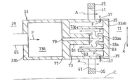
- the annular portion 33 for fuel injection is formed in a hollow shape, and this hollow space forms an annular fuel flow passage 73 through which the fuel F flows in the circumferential direction in the annular portion for fuel injection 33.
- the rear wall 33a of the fuel injection member 34 and a part of the inner wall of the annular fuel flow passage 73 are the same wall, the wall surface on the combustion chamber side is the rear wall surface 33ab, and the wall surface on the fuel flow passage side is the inner wall surface 33aa. It has become.
- the branch fuel supply pipe 66 is connected so as to supply the fuel F from the front wall (wall on the air supply passage 29 side) 33b side of the fuel injection member 34 to the annular fuel flow passage 73a.
- annular fuel flow passages 73 a and 73 b that are partitioned in the direction of the axis C of the combustion device 3 are formed.
- a downstream fuel flow passage 73b (first fuel flow passage) that is located on the rear side (combustion chamber 11 side) and supplies fuel F to the fuel injection holes 39
- An upstream fuel flow passage 73a (second fuel flow passage) that is positioned on the front side (air supply passage 29 side) and to which fuel F is directly supplied is formed.
- the annular first partition wall 77 that divides the upstream fuel flow passage 73a and the downstream fuel flow passage 73b has a through hole that guides fuel from the upstream fuel flow passage 73a to the downstream fuel flow passage 73b in the circumferential direction. A plurality are provided side by side.
- This through hole functions as a feed hole 79 that connects the two fuel flow passages 73a and 73b and feeds the fuel F from the upstream fuel flow passage 73a to the downstream fuel flow passage 73b.
- the fuel F introduced into the upstream fuel flow passage 73a from the branch fuel supply pipe 66 flows into the downstream fuel flow passage 73b sequentially through the feed holes 79 while flowing in the circumferential direction in the upstream fuel flow passage 73a. To do.
- the fuel F is divided by dividing the inside of the fuel injection annular portion 33 of the fuel injection member 34 into the upstream fuel flow passage 73a and the downstream fuel flow passage 73b in the direction of the axis C of the combustion device 3. It is supplied to the fuel injection holes 39 in a state of being uniformly distributed in the circumferential direction.
- the fuel F flowing into the downstream fuel flow passage 73b collides with the inner wall surface 33aa of the rear wall 33a, so that the fuel F impinges on the rear wall 33a.
- a nozzle wall 81 protruding rearward is provided on the first partition wall 77 in the circumferential direction, and a plurality of feed holes 79 are provided in the circumferential direction in the nozzle wall 81.
- the nozzle wall 81 forms an injection nozzle that injects the fuel F in the upstream fuel flow passage portion 73a to the back surface 33aa that is the wall surface on the combustion chamber 11 side of the downstream fuel flow passage portion 73b.
- the annular portion 33 for fuel injection is located on the combustion chamber 11 side, is located on the opposite side of the combustion chamber 11 from the downstream fuel flow passage 73b communicating with the fuel injection hole 39, and is injected from the fuel injection hole 39.
- An upstream fuel flow passage 73a to which the fuel F to be supplied is supplied, and an injection nozzle that injects the fuel F in the upstream fuel flow passage 73a to the inner wall surface 33aa on the combustion chamber 11 side of the downstream fuel flow passage 73b.
- the injection nozzle does not necessarily have the nozzle wall 81, and may be a throttle nozzle formed in the first partition wall 77.
- a protruding wall 83 extending in the circumferential direction projects into the inner wall surface 33aa of the rear wall 33a in the middle of the flow path from the inner wall surface 33aa of the rear wall 33a to which the fuel F is injected from the feed hole 79.
- the fuel F can be used to cool the rear wall 33a of the annular portion 33 for fuel injection facing the combustion chamber 11 by convection cooling from the inside (inner wall surface 33aa side).
- the fuel F supplied from each branch fuel supply pipe 66 flows almost evenly in the fuel flow passage 73, and the fuel F is supplied from the fuel flow passage 73 to the fuel injection holes 39 so that the effect of convection cooling can be sufficiently exhibited.
- You may provide the 2nd division wall 87 in the middle of being led to. That is, the annular fuel flow passage 73 may be divided into three annular spaces by the outer peripheral side partition wall 87a and the inner peripheral side partition wall 87b.
- a heat shield plate 85 may be provided on the rear wall 33ab of the rear wall 33a.
- the material for forming the heat shield plate 85 include Hastelloy-X (Haynes International. Inc .: registered trademark), HA188 (Haynes International. Inc .: registered trademark), which are alloys having corrosion resistance and heat resistance. Alternatively, a combination of these and a ceramic coating can be used. Also in the embodiment shown in FIG. 8, the heat shield plates 85 can be selectively combined.
- the rectifying protrusion member 63 is formed in a hollow shape as a whole.
- the support portion 63a of the rectifying projection member 63 is a bottomed cylindrical member, and a cooling air introduction hole 91 that is a radial through hole is provided on the peripheral wall of the front end (upstream end) thereof.
- a plurality of cooling air introduction holes 91 are formed at equal intervals in the circumferential direction of the peripheral wall at the front end of the support portion 63a.
- the protrusion 63 b of the rectifying projection member 63 has a double wall structure including a dome-shaped inner wall 93 and an outer wall 95 that are reduced in diameter toward the combustion chamber side (right side in FIG. 10).
- the protrusion part 63b may not be a dome shape, and a cylinder shape may be sufficient as it. Further, the protruding portion 63b may not have a double wall structure, but may have a single wall structure having only an outer wall.
- a first cooling air injection hole 97 which is a radial through hole, is provided on the peripheral wall of the inner wall 93 of the protrusion 63b. A plurality of first cooling air injection holes 97 are formed at equal intervals in the circumferential direction and the axial direction of the peripheral wall of the inner wall 93.
- a plurality of second cooling air injection holes 98 that are through holes extending obliquely rearward with respect to the radial direction are provided in the peripheral wall of the outer wall 95 of the protruding portion 63b.
- the plurality of second cooling air injection holes 98 are arranged at equal intervals in the circumferential direction and the axial direction of the peripheral wall of the outer wall 95.
- a cooling air discharge hole 99 that is a through-hole in the axial direction is provided at the center of the tip of the outer wall 95 of the protruding portion 63b. That is, the rectifying projection member 63 is formed at the front end of the support portion 63a, and is formed in the cooling air introduction hole 91 for introducing the air A upstream from the fuel injector 15 into the inside thereof, and the protruding portion 63b thereof.
- a cooling air discharge hole 99 for discharging the air A introduced into the combustion chamber 11 is provided.
- the inner space S formed by the support portion 63a and the inner wall 93 of the protrusion 63b and the gap G formed by the inner wall 93 and the outer wall 95 of the protrusion 63b are the first cooling air injection of the inner wall 93. It communicates only through the hole 97.
- a fitting projection wall 63aa projects from the opening edge of the support portion 63a, and the opening edge 93a of the inner wall 93 is fitted to the inner peripheral side of the fitting projection wall 63aa.
- the opening edge portion 95a of the outer wall 95 is fitted to the outer peripheral side of the fitting protruding wall 63aa.
- the protrusion 63b When the protrusion 63b has a single-wall structure with only the outer wall, a part of the air A in the air supply passage 29 flows into the inner space S of the rectifying protrusion member 63 from the cooling air introduction hole 91 and burns as a cooling medium.
- the projecting portion 63b facing the chamber 11 is discharged from the cooling air discharge hole 99 to the combustion chamber 11 while cooling by convection from the inside.
- the protruding portion 63b has a double wall structure including the inner wall 93 and the outer wall 95, a part of the air A flowing into the inner space S of the rectifying protrusion 63 from the cooling air introduction hole 91 is a cooling medium.
- the air A collides with the inner peripheral surface of the outer wall 95, and burns from the cooling air discharge hole 99 through the cooling passage which is the gap G between the inner wall 93 and the outer wall 95 along the inner peripheral surface. It is discharged into the chamber 11.
- the air A collides with the inner peripheral surface of the outer wall 95 and flows along the inner peripheral surface, whereby the outer wall 95 is impingement cooled from the inside.
- a part of the air A flowing into the gap G between the inner wall 93 and the outer wall 95 is discharged to the combustion chamber 11 through the second cooling air injection hole 98 of the outer wall 95.
- the air A blown out from the second cooling air injection hole 98 forms a film layer of air on the surface of the outer wall 95 and effusion cools the outer wall 95 from the outside. In this way, the burnout of the rectifying protrusion member 63 can be prevented. Note that the second cooling air injection hole 98 may be omitted.
- the outer peripheral surface of the outer wall 95 may be coated with a heat insulating material 100.
- a heat insulating material 100 ceramics, an alloy having corrosion resistance and heat resistance, Hastelloy-X (Haynes International. Inc .: registered trademark), HA188 (Haynes International. Inc .: registered trademark), or the like is used. Can do.
- the fuel injector 15 includes the fuel injection member 34 having the plurality of annular portions 33 for fuel injection.
- the injection annular portion 33 has a large number of fuel injection holes 39 on the outer peripheral surface thereof, so that the fuel F is uniformly injected from the entire surface of the fuel injector 15. Thereby, a fine flame is held at multiple points on the entire surface of the fuel injector 15. Thereby, the occurrence of local high-temperature combustion is prevented and low NOx combustion can be realized.
- the configuration in which the air A is supplied from the upstream to the fuel F injected from the fuel injection hole 39 prevents the flame from entering the fuel injector 15, thereby suppressing the backfire phenomenon.
- the combustion device 3 includes a premixing type burner 10 disposed in the downstream area of the combustion chamber 11 and on the peripheral wall of the combustion cylinder 13.
- the reheating burner 10 is operated in a state in which combustion by the fuel injector 15 that is a main burner is almost completed and high-temperature combustion gas G is generated, so that the reburning burner 10 is injected into the downstream region of the combustion chamber 11.
- the premixed gas M is burned stably while suppressing generation of NOx by the high-temperature combustion gas G.
- the reheating burner 10 according to the present embodiment does not require a swirl flow generating mechanism or the like (flame holding mechanism) for forming a backflow region for flame holding, and therefore has high resistance to backfire. Therefore, even when a highly reactive fuel containing hydrogen is used as the fuel for the gas turbine GT, extremely stable combustion is maintained while suppressing the generation of NOx.
- the fuel F used in the combustion device 3 of the present embodiment is not limited to hydrogen gas, and may be, for example, liquid hydrogen or a mixed fuel of hydrogen gas and other fuel gas (natural gas, CO, etc.). Furthermore, other fuel gas not containing hydrogen (natural gas, CO, etc.) may be used.
- the can-type combustion apparatus 3 has been described as an example. However, the above-described configuration can also be applied to an annular-type combustion apparatus.
- FIG. 11 and 12 show an embodiment in which the present invention is applied to a forward flow type annular combustion apparatus
- FIG. 13 shows an embodiment in which the present invention is applied to a reverse flow type annular combustion apparatus.
- the combustion apparatus 3 includes a combustion cylinder 13 that forms a combustion chamber 11 inside, a fuel injection member 34 that is provided at the top of the combustion cylinder 13 and includes a plurality of fuel injection annular portions 33, and combustion An air guide member 36 including a plurality of combustion air annular portions 35 for guiding air is provided, and the fuel injection annular portions 33 and the combustion air annular portions 35 are alternately arranged concentrically, and fuel is supplied to the combustion chamber 11.
- the fuel injection annular portion 33 has a plurality of fuel injection holes 39 opened in the radial direction R, and the combustion air annular portion 35 extends in the axial direction.
- a plurality of air guide grooves 41 that open and guide the air A to the fuel F injected from the fuel injection holes 39 are provided.
- the combustion cylinder 13 is constituted by a cylindrical inner wall 101 and an outer wall 103 arranged concentrically with the inner wall on the outer side of the inner wall 101.
- the space between the outer wall 103 and the outer wall 103 forms an annular combustion chamber 11.
- Air A compressed by the compressor 1 (FIG. 1) is introduced into the annular combustor housing H from the front through the diffuser 105 and is further supplied to the fuel injector 15.
- the front of the fuel injector 15 is covered with an air rectifying cowl 107 that is an air rectifying mechanism.
- the air rectifying cowl 107 is an annular member having a cross-sectional shape that bulges forward, and a plurality of holes through which the air A passes are formed.
- the combustion cylinder 13 is composed of a cylindrical inner wall 101 and an outer wall 103 arranged concentrically with the inner wall on the outer side of the inner wall 101. A space between 101 and the outer wall 103 forms an annular combustion chamber 11.
- the air A compressed by the compressor 1 passes from the rear through the air introduction passage 25 formed between the housing H and the combustion cylinder 13 and then is supplied to the fuel injector 15.
- the front of the fuel injector 15 is covered with an air rectifying cowl 107 that is an air rectifying mechanism.
- the air rectifying cowl 107 is an annular member having a cross-sectional shape that bulges forward, as in the example shown in FIG. 12, and has a number of holes through which air passes.
- Combustion device 10 Reheating burner 11 Combustion chamber 13 Combustion cylinder 15 Fuel injector 33 Fuel injection annular portion 34 Fuel injection member 35 Combustion air annular portion 36 Air guide member 39 Fuel injection hole 41 Air guide groove A Air C Combustor axis F Fuel
Landscapes
- Engineering & Computer Science (AREA)
- Chemical & Material Sciences (AREA)
- Combustion & Propulsion (AREA)
- Mechanical Engineering (AREA)
- General Engineering & Computer Science (AREA)
- Nozzles For Spraying Of Liquid Fuel (AREA)
Abstract
Description
更に、燃焼室の下流域の燃焼反応が進んだ領域に、追い焚きバーナを設けることにより、負荷変動への対応を実現できる。
したがって、ガスタービンエンジンの燃料として、例えば水素を含む反応性の高い燃料を使用する場合にも、NOxの発生を抑制しながら、極めて安定した燃焼が維持される。
また、各分岐燃料供給管66から供給される燃料Fが燃料流通路73内をほぼ均等に流れ、対流冷却の効果を十分に発揮できるように、燃料Fが燃料流通路73から燃料噴射孔39に導かれる途中に第2区画壁87を設けてもよい。つまり、環状の燃料流通路73は、外周側区画壁87aと内周側区画壁87bとによって、3つの環状の空間に分割されていてもよい。
10 追い焚きバーナ
11 燃焼室
13 燃焼筒
15 燃料噴射器
33 燃料噴射用環状部
34 燃料噴射部材
35 燃焼空気用環状部
36 空気ガイド部材
39 燃料噴射孔
41 空気ガイド溝
A 空気
C 燃焼装置軸心
F 燃料
Claims (8)
- 内側に燃焼室を形成する燃焼筒と、
前記燃焼筒の頂部に設けられ、複数の燃料噴射用環状部を含む燃料噴射部材および燃焼用空気を案内する複数の燃焼空気用環状部を含む空気ガイド部材を有し、前記燃料噴射用環状部と前記燃焼空気用環状部とが同心状に交互に配置され、前記燃焼室に燃料と空気を噴射する燃料噴射器と、
前記燃焼室の下流域であって、前記燃焼筒の周壁に配置された追い焚きバーナと、
を備え、
前記燃料噴射用環状部は、その径方向に開口する複数の燃料噴射孔を有し、
前記燃焼空気用環状部は、その軸心方向に開口し、前記燃料噴射孔から噴射される燃料に対して空気を案内する複数の空気ガイド溝を有する、燃焼装置。 - 請求項1に記載の燃焼装置において、前記追い焚きバーナは、燃料と空気とを混合撹拌する予混合室を有し、前記予混合室で生成された予混合気を前記燃焼室内へ噴射する、
燃焼装置。 - 請求項1または2に記載の燃焼装置において、さらに、前記燃料噴射器の上流に設けられ、前記空気ガイド部材に供給される空気を整流する空気整流機構を備える燃焼装置。
- 請求項1から3のいずれか一項に記載の燃焼装置において、燃焼装置の軸心上に設けられ、前記燃料噴射器を貫通して前記燃焼室に向かって突出する整流突起部材をさらに備える燃焼装置。
- 請求項4に記載の燃焼装置において、前記整流突起部材は、支持部と、この支持部から前記燃焼室内に突出する突出部とを含み、前記支持部に形成されて、空気を前記整流突起部材の内部に導入する冷却空気導入孔と、前記突出部に形成されて、前記整流突起部材の内部に導入された空気を前記燃焼室に排出する冷却空気排出孔とを有する燃焼装置。
- 請求項1から5のいずれか一項に記載の燃焼装置において、前記燃料噴射用環状部は中空状に形成されており、
前記燃料噴射用環状部内の中空空間が、燃料を周方向に流通させる環状の燃料流通路を形成している燃焼装置。 - 請求項6に記載の燃焼装置において、前記燃料噴射用環状部は、前記燃焼室側に位置し、前記燃料噴射孔と連通する第1燃料流通路と、前記燃焼室とは反対側に位置し、前記燃料噴射孔から噴射される燃料が供給される第2燃料流通路と、前記第2燃料流通路内の燃料を前記第1燃料流通路の前記燃焼室側の壁面へ噴射する噴射ノズルと、を有する燃焼装置。
- 請求項1から7のいずれか一項に記載の燃焼装置において、前記燃料噴射部材に燃料を供給する、多管式構造の燃料供給母管を有し、
この燃料供給母管は、前記複数の燃料噴射用環状部の第1環状群に燃料を供給する第1供給通路と、前記複数の燃料噴射用環状部の第2環状群に燃料を供給する第2供給通路とを有する燃焼装置。
Priority Applications (6)
| Application Number | Priority Date | Filing Date | Title |
|---|---|---|---|
| JP2016523566A JP6285022B2 (ja) | 2014-05-30 | 2015-05-28 | ガスタービンエンジンの燃焼装置 |
| CN201580028575.7A CN106537042B (zh) | 2014-05-30 | 2015-05-28 | 燃气涡轮发动机的燃烧装置 |
| EP15800273.3A EP3150918B1 (en) | 2014-05-30 | 2015-05-28 | Combustion device for gas turbine engine |
| AU2015268509A AU2015268509B2 (en) | 2014-05-30 | 2015-05-28 | Combustion device for gas turbine engine |
| CA2950566A CA2950566A1 (en) | 2014-05-30 | 2015-05-28 | Combustion device for gas turbine engine |
| US15/363,105 US20170074521A1 (en) | 2014-05-30 | 2016-11-29 | Combustion device for gas turbine engine |
Applications Claiming Priority (2)
| Application Number | Priority Date | Filing Date | Title |
|---|---|---|---|
| JP2014113269 | 2014-05-30 | ||
| JP2014-113269 | 2014-05-30 |
Related Child Applications (1)
| Application Number | Title | Priority Date | Filing Date |
|---|---|---|---|
| US15/363,105 Continuation US20170074521A1 (en) | 2014-05-30 | 2016-11-29 | Combustion device for gas turbine engine |
Publications (1)
| Publication Number | Publication Date |
|---|---|
| WO2015182727A1 true WO2015182727A1 (ja) | 2015-12-03 |
Family
ID=54699050
Family Applications (1)
| Application Number | Title | Priority Date | Filing Date |
|---|---|---|---|
| PCT/JP2015/065477 WO2015182727A1 (ja) | 2014-05-30 | 2015-05-28 | ガスタービンエンジンの燃焼装置 |
Country Status (7)
| Country | Link |
|---|---|
| US (1) | US20170074521A1 (ja) |
| EP (1) | EP3150918B1 (ja) |
| JP (1) | JP6285022B2 (ja) |
| CN (1) | CN106537042B (ja) |
| AU (1) | AU2015268509B2 (ja) |
| CA (1) | CA2950566A1 (ja) |
| WO (1) | WO2015182727A1 (ja) |
Cited By (10)
| Publication number | Priority date | Publication date | Assignee | Title |
|---|---|---|---|---|
| WO2017110955A1 (ja) * | 2015-12-22 | 2017-06-29 | 川崎重工業株式会社 | 燃料噴射装置 |
| WO2018212001A1 (ja) * | 2017-05-16 | 2018-11-22 | 川崎重工業株式会社 | ガスタービン燃焼器およびその運転方法 |
| JP2019002400A (ja) * | 2017-06-13 | 2019-01-10 | ゼネラル・エレクトリック・カンパニイ | 燃料供給アセンブリおよび関連する方法 |
| JP2019100571A (ja) * | 2017-11-29 | 2019-06-24 | 川崎重工業株式会社 | バーナ装置 |
| JP2020535381A (ja) * | 2017-07-21 | 2020-12-03 | キュッパース・ソリューションズ・ゲゼルシャフト・ミト・ベシュレンクテル・ハフツング | バーナー |
| WO2022050259A1 (ja) * | 2020-09-04 | 2022-03-10 | 三菱重工業株式会社 | ガスタービン燃焼器の多孔板、ガスタービン燃焼器及びガスタービン |
| WO2022249938A1 (ja) * | 2021-05-28 | 2022-12-01 | 川崎重工業株式会社 | ガスタービン燃焼器 |
| CN115597087A (zh) * | 2022-08-12 | 2023-01-13 | 中国航发沈阳发动机研究所(Cn) | 一种扩张型射流孔的氢燃料燃烧室头部结构 |
| WO2023145218A1 (ja) * | 2022-01-31 | 2023-08-03 | 株式会社Ihi | 燃焼装置およびガスタービンシステム |
| JP7470855B1 (ja) | 2023-09-19 | 2024-04-18 | 東京瓦斯株式会社 | 水素燃焼式ダクトバーナ |
Families Citing this family (16)
| Publication number | Priority date | Publication date | Assignee | Title |
|---|---|---|---|---|
| CA2950558C (en) * | 2014-05-30 | 2020-10-20 | Kawasaki Jukogyo Kabushiki Kaisha | Combustor for gas turbine engine |
| US10364751B2 (en) * | 2015-08-03 | 2019-07-30 | Delavan Inc | Fuel staging |
| US10215038B2 (en) * | 2016-05-26 | 2019-02-26 | Siemens Energy, Inc. | Method and computer-readable model for additively manufacturing ducting arrangement for a gas turbine engine |
| CN108731029B (zh) | 2017-04-25 | 2021-10-29 | 帕克-汉尼芬公司 | 喷气燃料喷嘴 |
| JP6941576B2 (ja) * | 2018-03-26 | 2021-09-29 | 三菱パワー株式会社 | 燃焼器及びそれを備えるガスタービン |
| JP7260365B2 (ja) * | 2019-03-29 | 2023-04-18 | 川崎重工業株式会社 | 予混合燃焼バーナ |
| FR3101696B1 (fr) * | 2019-10-08 | 2021-10-29 | Safran Helicopter Engines | Canne de prevaporisation pour une chambre de combustion de turbomachine |
| CN113531584B (zh) * | 2020-04-15 | 2023-05-23 | 上海慕帆动力科技有限公司 | 燃气轮机的燃烧装置 |
| CN113932253B (zh) * | 2020-06-29 | 2022-10-18 | 中国航发商用航空发动机有限责任公司 | 燃烧室头部、燃烧室、燃气涡轮发动机及燃烧控制方法 |
| KR102382634B1 (ko) * | 2020-12-22 | 2022-04-01 | 두산중공업 주식회사 | 연소기용 노즐, 연소기 및 이를 포함하는 가스 터빈 |
| CN114183772A (zh) * | 2021-11-30 | 2022-03-15 | 哈尔滨工程大学 | 一种氢气预混的高效低排放燃烧室头部 |
| CN114294680B (zh) * | 2021-12-29 | 2023-07-04 | 哈尔滨工业大学 | 一种中心分级燃气轮机微预混燃烧室 |
| KR102583223B1 (ko) * | 2022-01-28 | 2023-09-25 | 두산에너빌리티 주식회사 | 연소기용 노즐, 연소기 및 이를 포함하는 가스터빈 |
| KR102607177B1 (ko) * | 2022-01-28 | 2023-11-29 | 두산에너빌리티 주식회사 | 연소기용 노즐, 연소기 및 이를 포함하는 가스터빈 |
| CN114754378B (zh) * | 2022-06-13 | 2022-08-19 | 成都中科翼能科技有限公司 | 一种燃气轮机燃烧器结构 |
| CN115355531B (zh) * | 2022-08-12 | 2023-06-20 | 中国航发沈阳发动机研究所 | 一种半跑道型射流孔的氢燃料燃烧室头部结构 |
Citations (6)
| Publication number | Priority date | Publication date | Assignee | Title |
|---|---|---|---|---|
| JP2002364849A (ja) * | 2001-06-07 | 2002-12-18 | Mitsubishi Heavy Ind Ltd | 燃焼器 |
| WO2006100983A1 (ja) * | 2005-03-18 | 2006-09-28 | Kawasaki Jukogyo Kabushiki Kaisha | ガスタービン燃焼器およびその着火方法 |
| WO2009022449A1 (ja) * | 2007-08-10 | 2009-02-19 | Kawasaki Jukogyo Kabushiki Kaisha | 燃焼装置 |
| JP2012141078A (ja) * | 2010-12-28 | 2012-07-26 | Kawasaki Heavy Ind Ltd | 燃焼装置、及び該燃焼装置の燃焼制御方法 |
| JP2012149869A (ja) * | 2011-01-18 | 2012-08-09 | General Electric Co <Ge> | 燃料噴射システム及び方法 |
| JP2013190201A (ja) * | 2012-03-12 | 2013-09-26 | General Electric Co <Ge> | 複数管燃料ノズルにおける混合を強化するシステム |
Family Cites Families (20)
| Publication number | Priority date | Publication date | Assignee | Title |
|---|---|---|---|---|
| US5361586A (en) * | 1993-04-15 | 1994-11-08 | Westinghouse Electric Corporation | Gas turbine ultra low NOx combustor |
| JP3183053B2 (ja) * | 1994-07-20 | 2001-07-03 | 株式会社日立製作所 | ガスタービン燃焼器及びガスタービン |
| US5421158A (en) * | 1994-10-21 | 1995-06-06 | General Electric Company | Segmented centerbody for a double annular combustor |
| US6267585B1 (en) * | 1995-12-19 | 2001-07-31 | Daimlerchrysler Aerospace Airbus Gmbh | Method and combustor for combusting hydrogen |
| DE19547506B4 (de) * | 1995-12-19 | 2008-06-05 | Airbus Deutschland Gmbh | Verfahren und Brenner zum Verbrennen von Wasserstoff |
| JP3742722B2 (ja) * | 1998-03-16 | 2006-02-08 | 財団法人電力中央研究所 | ガスタービン燃焼器 |
| US7007477B2 (en) * | 2004-06-03 | 2006-03-07 | General Electric Company | Premixing burner with impingement cooled centerbody and method of cooling centerbody |
| US8511097B2 (en) * | 2005-03-18 | 2013-08-20 | Kawasaki Jukogyo Kabushiki Kaisha | Gas turbine combustor and ignition method of igniting fuel mixture in the same |
| US8539773B2 (en) * | 2009-02-04 | 2013-09-24 | General Electric Company | Premixed direct injection nozzle for highly reactive fuels |
| US8424311B2 (en) * | 2009-02-27 | 2013-04-23 | General Electric Company | Premixed direct injection disk |
| JP4797079B2 (ja) * | 2009-03-13 | 2011-10-19 | 川崎重工業株式会社 | ガスタービン燃焼器 |
| US8418468B2 (en) * | 2010-04-06 | 2013-04-16 | General Electric Company | Segmented annular ring-manifold quaternary fuel distributor |
| US8919673B2 (en) * | 2010-04-14 | 2014-12-30 | General Electric Company | Apparatus and method for a fuel nozzle |
| JP5524407B2 (ja) * | 2011-03-16 | 2014-06-18 | 三菱重工業株式会社 | ガスタービン燃焼器およびガスタービン |
| US20130219899A1 (en) * | 2012-02-27 | 2013-08-29 | General Electric Company | Annular premixed pilot in fuel nozzle |
| US9212822B2 (en) * | 2012-05-30 | 2015-12-15 | General Electric Company | Fuel injection assembly for use in turbine engines and method of assembling same |
| US9310078B2 (en) * | 2012-10-31 | 2016-04-12 | General Electric Company | Fuel injection assemblies in combustion turbine engines |
| US9546789B2 (en) * | 2013-03-15 | 2017-01-17 | General Electric Company | System having a multi-tube fuel nozzle |
| US10018359B2 (en) * | 2013-11-05 | 2018-07-10 | Mitsubishi Hitachi Power Systems, Ltd. | Gas turbine combustor |
| CA2950558C (en) * | 2014-05-30 | 2020-10-20 | Kawasaki Jukogyo Kabushiki Kaisha | Combustor for gas turbine engine |
-
2015
- 2015-05-28 JP JP2016523566A patent/JP6285022B2/ja active Active
- 2015-05-28 CA CA2950566A patent/CA2950566A1/en not_active Abandoned
- 2015-05-28 CN CN201580028575.7A patent/CN106537042B/zh active Active
- 2015-05-28 EP EP15800273.3A patent/EP3150918B1/en active Active
- 2015-05-28 AU AU2015268509A patent/AU2015268509B2/en active Active
- 2015-05-28 WO PCT/JP2015/065477 patent/WO2015182727A1/ja active Application Filing
-
2016
- 2016-11-29 US US15/363,105 patent/US20170074521A1/en not_active Abandoned
Patent Citations (6)
| Publication number | Priority date | Publication date | Assignee | Title |
|---|---|---|---|---|
| JP2002364849A (ja) * | 2001-06-07 | 2002-12-18 | Mitsubishi Heavy Ind Ltd | 燃焼器 |
| WO2006100983A1 (ja) * | 2005-03-18 | 2006-09-28 | Kawasaki Jukogyo Kabushiki Kaisha | ガスタービン燃焼器およびその着火方法 |
| WO2009022449A1 (ja) * | 2007-08-10 | 2009-02-19 | Kawasaki Jukogyo Kabushiki Kaisha | 燃焼装置 |
| JP2012141078A (ja) * | 2010-12-28 | 2012-07-26 | Kawasaki Heavy Ind Ltd | 燃焼装置、及び該燃焼装置の燃焼制御方法 |
| JP2012149869A (ja) * | 2011-01-18 | 2012-08-09 | General Electric Co <Ge> | 燃料噴射システム及び方法 |
| JP2013190201A (ja) * | 2012-03-12 | 2013-09-26 | General Electric Co <Ge> | 複数管燃料ノズルにおける混合を強化するシステム |
Cited By (19)
| Publication number | Priority date | Publication date | Assignee | Title |
|---|---|---|---|---|
| JP2017116158A (ja) * | 2015-12-22 | 2017-06-29 | 川崎重工業株式会社 | 燃料噴射装置 |
| US10612470B2 (en) | 2015-12-22 | 2020-04-07 | Kawasaki Jukogyo Kabushiki Kaisha | Fuel injection device |
| WO2017110955A1 (ja) * | 2015-12-22 | 2017-06-29 | 川崎重工業株式会社 | 燃料噴射装置 |
| WO2018212001A1 (ja) * | 2017-05-16 | 2018-11-22 | 川崎重工業株式会社 | ガスタービン燃焼器およびその運転方法 |
| JP2018194210A (ja) * | 2017-05-16 | 2018-12-06 | 川崎重工業株式会社 | ガスタービン燃焼器およびその運転方法 |
| US11421599B2 (en) | 2017-05-16 | 2022-08-23 | Kawasaki Jukogyo Kabushiki Kaisha | Gas turbine combustor and operating method thereof |
| JP2019002400A (ja) * | 2017-06-13 | 2019-01-10 | ゼネラル・エレクトリック・カンパニイ | 燃料供給アセンブリおよび関連する方法 |
| JP7187181B2 (ja) | 2017-06-13 | 2022-12-12 | ゼネラル・エレクトリック・カンパニイ | 燃料供給アセンブリおよび関連する方法 |
| JP2020535381A (ja) * | 2017-07-21 | 2020-12-03 | キュッパース・ソリューションズ・ゲゼルシャフト・ミト・ベシュレンクテル・ハフツング | バーナー |
| JP7126346B2 (ja) | 2017-11-29 | 2022-08-26 | 川崎重工業株式会社 | バーナ装置 |
| JP2019100571A (ja) * | 2017-11-29 | 2019-06-24 | 川崎重工業株式会社 | バーナ装置 |
| WO2022050259A1 (ja) * | 2020-09-04 | 2022-03-10 | 三菱重工業株式会社 | ガスタービン燃焼器の多孔板、ガスタービン燃焼器及びガスタービン |
| JP2022043702A (ja) * | 2020-09-04 | 2022-03-16 | 三菱パワー株式会社 | ガスタービン燃焼器の多孔板、ガスタービン燃焼器及びガスタービン |
| US12031723B2 (en) | 2020-09-04 | 2024-07-09 | Mitsubishi Heavy Industries, Ltd. | Perforated plate for gas turbine combustor, gas turbine combustor, and gas turbine |
| WO2022249938A1 (ja) * | 2021-05-28 | 2022-12-01 | 川崎重工業株式会社 | ガスタービン燃焼器 |
| WO2023145218A1 (ja) * | 2022-01-31 | 2023-08-03 | 株式会社Ihi | 燃焼装置およびガスタービンシステム |
| CN115597087A (zh) * | 2022-08-12 | 2023-01-13 | 中国航发沈阳发动机研究所(Cn) | 一种扩张型射流孔的氢燃料燃烧室头部结构 |
| CN115597087B (zh) * | 2022-08-12 | 2024-02-23 | 中国航发沈阳发动机研究所 | 一种扩张型射流孔的氢燃料燃烧室头部结构 |
| JP7470855B1 (ja) | 2023-09-19 | 2024-04-18 | 東京瓦斯株式会社 | 水素燃焼式ダクトバーナ |
Also Published As
| Publication number | Publication date |
|---|---|
| US20170074521A1 (en) | 2017-03-16 |
| JP6285022B2 (ja) | 2018-02-28 |
| EP3150918A4 (en) | 2018-01-10 |
| CN106537042B (zh) | 2019-05-14 |
| AU2015268509B2 (en) | 2018-04-26 |
| CA2950566A1 (en) | 2015-12-03 |
| AU2015268509A1 (en) | 2016-12-15 |
| JPWO2015182727A1 (ja) | 2017-04-20 |
| EP3150918A1 (en) | 2017-04-05 |
| EP3150918B1 (en) | 2019-12-18 |
| CN106537042A (zh) | 2017-03-22 |
Similar Documents
| Publication | Publication Date | Title |
|---|---|---|
| JP6285022B2 (ja) | ガスタービンエンジンの燃焼装置 | |
| JP6285081B2 (ja) | ガスタービンエンジンの燃焼装置 | |
| US9366441B2 (en) | Burner, combustor and remodeling method for burner | |
| JP5400936B2 (ja) | ガスタービンエンジン内で燃料を燃焼させるための方法及び装置 | |
| JP5528756B2 (ja) | 二次燃料ノズル用の管状燃料噴射器 | |
| JP5199172B2 (ja) | 燃焼器ノズル | |
| WO2013183618A1 (ja) | 燃料噴射装置 | |
| JP5458121B2 (ja) | ガスタービン燃焼器およびガスタービン燃焼器の運転方法 | |
| US20170307210A1 (en) | Gas turbine combustor and gas turbine | |
| JP2006112776A (ja) | 低コスト二元燃料燃焼器及び関連する方法 | |
| JP2010203758A (ja) | 予混合式直接噴射ディスク | |
| JP2011141113A (ja) | 内蔵通路を備えた燃料ノズル及びその作動方法 | |
| JP2012042194A (ja) | 燃料噴射ノズル本体上の火炎安定化用のディンプル付き/グルーブ付き面及び関連する方法 | |
| JP2016057056A (ja) | ガスタービンの燃焼器用の希釈ガス又は空気混合器 | |
| JP2010133621A (ja) | ガスタービン燃焼器 | |
| JP2011196680A (ja) | 低排出燃焼システム用マルチゾーンパイロット | |
| JP2016023916A (ja) | ガスタービン燃焼器 | |
| JP2014105886A (ja) | 燃焼器 | |
| JP5462449B2 (ja) | 燃焼装置のバーナおよびこれを備えた燃焼装置 | |
| JP2014112003A (ja) | 燃焼器 |
Legal Events
| Date | Code | Title | Description |
|---|---|---|---|
| 121 | Ep: the epo has been informed by wipo that ep was designated in this application |
Ref document number: 15800273 Country of ref document: EP Kind code of ref document: A1 |
|
| ENP | Entry into the national phase |
Ref document number: 2950566 Country of ref document: CA |
|
| ENP | Entry into the national phase |
Ref document number: 2016523566 Country of ref document: JP Kind code of ref document: A |
|
| NENP | Non-entry into the national phase |
Ref country code: DE |
|
| ENP | Entry into the national phase |
Ref document number: 2015268509 Country of ref document: AU Date of ref document: 20150528 Kind code of ref document: A |
|
| REEP | Request for entry into the european phase |
Ref document number: 2015800273 Country of ref document: EP |
|
| WWE | Wipo information: entry into national phase |
Ref document number: 2015800273 Country of ref document: EP |