WO2015182594A1 - Dispositif radar monté sur véhicule - Google Patents
Dispositif radar monté sur véhicule Download PDFInfo
- Publication number
- WO2015182594A1 WO2015182594A1 PCT/JP2015/065065 JP2015065065W WO2015182594A1 WO 2015182594 A1 WO2015182594 A1 WO 2015182594A1 JP 2015065065 W JP2015065065 W JP 2015065065W WO 2015182594 A1 WO2015182594 A1 WO 2015182594A1
- Authority
- WO
- WIPO (PCT)
- Prior art keywords
- frequency
- interference
- vehicle
- radar device
- signal
- Prior art date
Links
Images

Classifications
-
- G—PHYSICS
- G01—MEASURING; TESTING
- G01S—RADIO DIRECTION-FINDING; RADIO NAVIGATION; DETERMINING DISTANCE OR VELOCITY BY USE OF RADIO WAVES; LOCATING OR PRESENCE-DETECTING BY USE OF THE REFLECTION OR RERADIATION OF RADIO WAVES; ANALOGOUS ARRANGEMENTS USING OTHER WAVES
- G01S7/00—Details of systems according to groups G01S13/00, G01S15/00, G01S17/00
- G01S7/02—Details of systems according to groups G01S13/00, G01S15/00, G01S17/00 of systems according to group G01S13/00
- G01S7/023—Interference mitigation, e.g. reducing or avoiding non-intentional interference with other HF-transmitters, base station transmitters for mobile communication or other radar systems, e.g. using electro-magnetic interference [EMI] reduction techniques
-
- G—PHYSICS
- G01—MEASURING; TESTING
- G01S—RADIO DIRECTION-FINDING; RADIO NAVIGATION; DETERMINING DISTANCE OR VELOCITY BY USE OF RADIO WAVES; LOCATING OR PRESENCE-DETECTING BY USE OF THE REFLECTION OR RERADIATION OF RADIO WAVES; ANALOGOUS ARRANGEMENTS USING OTHER WAVES
- G01S13/00—Systems using the reflection or reradiation of radio waves, e.g. radar systems; Analogous systems using reflection or reradiation of waves whose nature or wavelength is irrelevant or unspecified
- G01S13/02—Systems using reflection of radio waves, e.g. primary radar systems; Analogous systems
- G01S13/06—Systems determining position data of a target
- G01S13/08—Systems for measuring distance only
- G01S13/32—Systems for measuring distance only using transmission of continuous waves, whether amplitude-, frequency-, or phase-modulated, or unmodulated
- G01S13/34—Systems for measuring distance only using transmission of continuous waves, whether amplitude-, frequency-, or phase-modulated, or unmodulated using transmission of continuous, frequency-modulated waves while heterodyning the received signal, or a signal derived therefrom, with a locally-generated signal related to the contemporaneously transmitted signal
- G01S13/345—Systems for measuring distance only using transmission of continuous waves, whether amplitude-, frequency-, or phase-modulated, or unmodulated using transmission of continuous, frequency-modulated waves while heterodyning the received signal, or a signal derived therefrom, with a locally-generated signal related to the contemporaneously transmitted signal using triangular modulation
-
- G—PHYSICS
- G01—MEASURING; TESTING
- G01S—RADIO DIRECTION-FINDING; RADIO NAVIGATION; DETERMINING DISTANCE OR VELOCITY BY USE OF RADIO WAVES; LOCATING OR PRESENCE-DETECTING BY USE OF THE REFLECTION OR RERADIATION OF RADIO WAVES; ANALOGOUS ARRANGEMENTS USING OTHER WAVES
- G01S13/00—Systems using the reflection or reradiation of radio waves, e.g. radar systems; Analogous systems using reflection or reradiation of waves whose nature or wavelength is irrelevant or unspecified
- G01S13/02—Systems using reflection of radio waves, e.g. primary radar systems; Analogous systems
- G01S13/06—Systems determining position data of a target
- G01S13/08—Systems for measuring distance only
- G01S13/32—Systems for measuring distance only using transmission of continuous waves, whether amplitude-, frequency-, or phase-modulated, or unmodulated
- G01S13/34—Systems for measuring distance only using transmission of continuous waves, whether amplitude-, frequency-, or phase-modulated, or unmodulated using transmission of continuous, frequency-modulated waves while heterodyning the received signal, or a signal derived therefrom, with a locally-generated signal related to the contemporaneously transmitted signal
- G01S13/347—Systems for measuring distance only using transmission of continuous waves, whether amplitude-, frequency-, or phase-modulated, or unmodulated using transmission of continuous, frequency-modulated waves while heterodyning the received signal, or a signal derived therefrom, with a locally-generated signal related to the contemporaneously transmitted signal using more than one modulation frequency
-
- G—PHYSICS
- G01—MEASURING; TESTING
- G01S—RADIO DIRECTION-FINDING; RADIO NAVIGATION; DETERMINING DISTANCE OR VELOCITY BY USE OF RADIO WAVES; LOCATING OR PRESENCE-DETECTING BY USE OF THE REFLECTION OR RERADIATION OF RADIO WAVES; ANALOGOUS ARRANGEMENTS USING OTHER WAVES
- G01S13/00—Systems using the reflection or reradiation of radio waves, e.g. radar systems; Analogous systems using reflection or reradiation of waves whose nature or wavelength is irrelevant or unspecified
- G01S13/02—Systems using reflection of radio waves, e.g. primary radar systems; Analogous systems
- G01S13/06—Systems determining position data of a target
- G01S13/08—Systems for measuring distance only
- G01S13/32—Systems for measuring distance only using transmission of continuous waves, whether amplitude-, frequency-, or phase-modulated, or unmodulated
- G01S13/36—Systems for measuring distance only using transmission of continuous waves, whether amplitude-, frequency-, or phase-modulated, or unmodulated with phase comparison between the received signal and the contemporaneously transmitted signal
- G01S13/38—Systems for measuring distance only using transmission of continuous waves, whether amplitude-, frequency-, or phase-modulated, or unmodulated with phase comparison between the received signal and the contemporaneously transmitted signal wherein more than one modulation frequency is used
-
- G—PHYSICS
- G01—MEASURING; TESTING
- G01S—RADIO DIRECTION-FINDING; RADIO NAVIGATION; DETERMINING DISTANCE OR VELOCITY BY USE OF RADIO WAVES; LOCATING OR PRESENCE-DETECTING BY USE OF THE REFLECTION OR RERADIATION OF RADIO WAVES; ANALOGOUS ARRANGEMENTS USING OTHER WAVES
- G01S13/00—Systems using the reflection or reradiation of radio waves, e.g. radar systems; Analogous systems using reflection or reradiation of waves whose nature or wavelength is irrelevant or unspecified
- G01S13/87—Combinations of radar systems, e.g. primary radar and secondary radar
-
- G—PHYSICS
- G01—MEASURING; TESTING
- G01S—RADIO DIRECTION-FINDING; RADIO NAVIGATION; DETERMINING DISTANCE OR VELOCITY BY USE OF RADIO WAVES; LOCATING OR PRESENCE-DETECTING BY USE OF THE REFLECTION OR RERADIATION OF RADIO WAVES; ANALOGOUS ARRANGEMENTS USING OTHER WAVES
- G01S13/00—Systems using the reflection or reradiation of radio waves, e.g. radar systems; Analogous systems using reflection or reradiation of waves whose nature or wavelength is irrelevant or unspecified
- G01S13/88—Radar or analogous systems specially adapted for specific applications
- G01S13/93—Radar or analogous systems specially adapted for specific applications for anti-collision purposes
- G01S13/931—Radar or analogous systems specially adapted for specific applications for anti-collision purposes of land vehicles
-
- G—PHYSICS
- G01—MEASURING; TESTING
- G01S—RADIO DIRECTION-FINDING; RADIO NAVIGATION; DETERMINING DISTANCE OR VELOCITY BY USE OF RADIO WAVES; LOCATING OR PRESENCE-DETECTING BY USE OF THE REFLECTION OR RERADIATION OF RADIO WAVES; ANALOGOUS ARRANGEMENTS USING OTHER WAVES
- G01S7/00—Details of systems according to groups G01S13/00, G01S15/00, G01S17/00
- G01S7/02—Details of systems according to groups G01S13/00, G01S15/00, G01S17/00 of systems according to group G01S13/00
- G01S7/023—Interference mitigation, e.g. reducing or avoiding non-intentional interference with other HF-transmitters, base station transmitters for mobile communication or other radar systems, e.g. using electro-magnetic interference [EMI] reduction techniques
- G01S7/0232—Avoidance by frequency multiplex
-
- G—PHYSICS
- G01—MEASURING; TESTING
- G01S—RADIO DIRECTION-FINDING; RADIO NAVIGATION; DETERMINING DISTANCE OR VELOCITY BY USE OF RADIO WAVES; LOCATING OR PRESENCE-DETECTING BY USE OF THE REFLECTION OR RERADIATION OF RADIO WAVES; ANALOGOUS ARRANGEMENTS USING OTHER WAVES
- G01S7/00—Details of systems according to groups G01S13/00, G01S15/00, G01S17/00
- G01S7/02—Details of systems according to groups G01S13/00, G01S15/00, G01S17/00 of systems according to group G01S13/00
- G01S7/023—Interference mitigation, e.g. reducing or avoiding non-intentional interference with other HF-transmitters, base station transmitters for mobile communication or other radar systems, e.g. using electro-magnetic interference [EMI] reduction techniques
- G01S7/0235—Avoidance by time multiplex
Definitions
- the present invention relates to an on-vehicle radar device that is mounted on a vehicle and detects a target using a radar wave.
- In-vehicle radar receives not only the reflected wave of the radar wave transmitted from the in-vehicle radar of the own vehicle, but also the radar wave transmitted from the in-vehicle radar of another vehicle in the vicinity of the own vehicle such as an oncoming vehicle or a parallel vehicle. May end up. As a result, interference between so-called in-vehicle radars may occur.
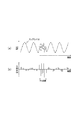
- the waveform of the beat signal is a signal having a high frequency due to interference to the waveform of the beat signal to be detected.
- the component waveform is superimposed (see FIG. 5A).
- the influence of interference (difference frequency component between the transmission wave and the interference wave) appears in the frequency band of the beat signal to be processed by the in-vehicle radar device.
- this is limited to a short period in the vicinity where the frequencies of the interfering radar waves intersect each other. For this reason, it is possible to suppress the influence of interference by shaping the waveform of the part affected by the interference, for example, by software.
- the on-vehicle radar device includes interference determination means, selection means, and frequency change means.
- the interference determination means determines the presence or absence of interference between multi-frequency CWs that are radar waves, based on a beat signal that is generated by mixing a transmission signal and a reception signal of radar waves.
- the selection unit selects either the own device or the counterpart device that is the interference partner according to the state of occurrence of the interference.
- the frequency changing unit changes the center frequency of the multi-frequency CW transmitted from the own device when the own device is selected by the selecting unit.
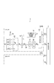
- the in-vehicle radar device 1 to which the present invention is applied includes a pair of radar sensors 3 (3R, 3L) and an integrated processing unit 5, as shown in FIG.
- the radar sensors 3 are provided at the left and right ends of a bumper provided at the rear end of the vehicle, respectively, and both have the same configuration.
- the radar sensor 3 positioned at the right end of the bumper is referred to as a right sensor 3R
- the radar sensor 3 positioned at the left end of the bumper is referred to as a left sensor 3L.
- the right sensor 3R is set so that an area extending from the right side of the vehicle to the right rear is an exploration range
- the left sensor 3L is set to an area extending from the left side of the vehicle to the left rear.
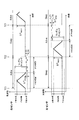
- the radar sensor 3 includes a voltage controlled oscillator 10 with a PLL (Phase Locked Loop) circuit, a distributor 14, a transmission antenna 16, a reception antenna unit 20, a reception switch 22, a mixer 24, an amplifier 26, and an LPF (LPF). Low Pass Filter 27, A / D (analog-digital) converter 28, and signal processing unit 30 are provided.
- PLL Phase Locked Loop
- the voltage-controlled oscillator 10 with a PLL circuit is a well-known one including a reference signal oscillator, a frequency divider, a phase comparator, a voltage-controlled oscillator, and the like, and controls signal processing by controlling the frequency division number in the frequency divider.
- a millimeter wave band signal having a frequency according to the frequency control signal Cf from the unit 30 is generated.
- the distributor 14 distributes the power of the output of the voltage controlled oscillator 10 with a PLL circuit to the transmission signal Ss and the local signal L, and supplies the transmission signal Ss to the transmission antenna 16 and the local signal L to the mixer 24.
- the transmission antenna 16 radiates a radar wave according to the transmission signal Ss.
- the receiving antenna unit 20 includes N antennas that receive radar waves.
- the reception switch 22 selects any one of the antennas constituting the reception antenna unit 20 in order, and supplies the reception signal Sr from the selected antenna to the mixer 24.
- the mixer 24 mixes the local signal L with the received signal Sr to generate a beat signal B and supplies it to the amplifier 26.
- the amplifier 26 amplifies the beat signal B and supplies it to the LPF 27.
- the LPF 27 uses the sampling frequency of the A / D converter 28 as fs, removes a signal component having a frequency of fs / 2 or more from the beat signal B amplified by the amplifier 26, and supplies the signal to the A / D converter 28. .
- the A / D converter 28 samples the output of the LPF 27 at the sampling frequency fs, converts it into digital data (hereinafter referred to as “sampling data”) Db, and supplies the digital data to the signal processing unit 30.
- the signal processing unit 30 is configured around a well-known microcomputer including a CPU, a ROM, and a RAM. Further, the signal processing such as fast Fourier transform (FFT) processing is performed on the data taken in via the A / D converter 28. Is provided.
- the signal processing unit 30 executes at least transmission processing and target detection processing.
- a desired radar wave is transmitted by generating a frequency control signal Cf according to a predetermined schedule in accordance with the timing signal TCi (TC1 for the right sensor 3R, TC2 for the left sensor) from the integrated processing unit 5.
- the target detection process generates information (target information) TG related to the target reflecting the radar wave based on the sampling data Db obtained during the transmission period of the radar wave, and integrates the target information TG. 5 is supplied.
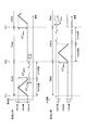
- the first half operates as an FMCW radar
- the second half operates as a two-frequency CW (2FCW) radar.
- the frequency band of 200 MHz (24.05 GHz to 24.25 GHz) defined by the Radio Law is applied to the lower CW band of 10 MHz width (24.05 GHz to 24.06 GHz) and 180 MHz width (24.06 to 24.24 GHz).
- the FMCW band is assigned to FMCW modulation (common to the right sensor 3R and the left sensor 3L).
- the lower CW band is assigned to 2FCW modulation of the right sensor 3R.
- the upper CW band is assigned to 2FCW modulation of the left sensor 3L.
- FMCW modulation an FMCW having a modulation width ⁇ F FMCW of 180 MHz is generated using the entire frequency region of the FMCW band.
- R_F0 and R_F1 two types of frequencies used in the right sensor 3R
- R_F1 and R_F1 two types of frequencies used in the right sensor 3R
- RF Two types of frequencies used in the left sensor 3L
- L_F0 and L_F1 Two types of frequencies used in the left sensor 3L are represented by L_F0 and L_F1, and their center frequencies are represented by LF.
- the center frequency RF is set to the center frequency RF by a predetermined step frequency F STEP with the frequencies R_F0 and R_F1 set so that the center frequency RF matches the lower limit frequency of the lower CW band as the home position. It is set to be able to increase.
- the center frequency LF can be decreased by the step frequency F STEP by using the frequencies L_F0 and L_F1 set so that the center frequency LF matches the upper limit frequency of the upper CW band as the home position.
- the frequency used for 2FCW modulation is initially set to the home position.
- the step frequency F STEP is set based on the difference between the upper limit frequency of the passband and the frequency whose amplitude is sufficiently small (for example, 1/10) based on the cutoff characteristic of the LPF 27.
- the target detection process includes an FMCW target detection process that is a process based on sampling data obtained during the FMCW modulation period and a 2FCW target detection process that is a process based on sampling data obtained during the 2FCW modulation period. It is executed during a stop period in which no wave transmission / reception is performed.
- the FMCW target detection process is well-known, including countermeasures when interference with radar waves (FMCW, 2FCW) transmitted from other vehicles occurs, and thus description thereof is omitted.
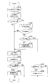
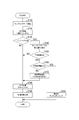
- the CPU of the signal processing unit 30 (hereinafter referred to as the signal processing unit 30) first reads the sampling data Db acquired in the 2FCW modulation period in step S110.
- the signal processing unit 30 performs frequency analysis processing (in this case, FFT processing) on the sampling data acquired for one designated channel set in advance.
- step S130 the signal processing unit 30 compares the noise floor calculated from the processing result in step S120 with the reference value of the noise floor calculated based on the processing result up to the previous processing cycle (reference It is determined whether or not the value is higher than a predetermined value set in advance. If the noise floor has not risen (S130: NO), the process proceeds to step S180, assuming that no interference has occurred. If the noise floor is rising (S130: YES), the process proceeds to step S140, assuming that interference has occurred.
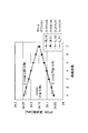
- the difference frequency component in the vicinity where the transmission wave from the own apparatus (here 2FCW) intersects the frequency of the interference wave is a frequency necessary for target detection. Appears in the band (hereinafter referred to as “detection target frequency band”), and this raises the noise floor.
- detection target frequency band the band
- the interference wave is 2FCW
- the transmission wave from the own device and the interference wave use the same frequencies F0 and F1
- the difference frequency component is out of the detection target frequency band, the LPF 27 does not sufficiently remove it because the A / D converter 28 performs oversampling.
- the difference frequency component is returned to the detection target frequency band and detected as a result of the FFT processing, and the noise floor is raised. That is, by examining the noise floor, it is possible to detect the presence or absence of interference regardless of whether the interference wave is FMCW or 2FCW.
- step S140 the signal processing unit 30 calculates a change amount DV (see FIG. 5B) of the signal level of the beat signal between the sampling points based on the sampling data (see FIG. 5A).
- step S150 the signal processing unit 30 determines whether or not there is an interference section in which the absolute value
- the voltage threshold Vth is set to the lower limit value of the change amount DV detected when a noise component of 1 MHz or higher is superimposed on the beat signal.
- the signal processing unit 30 determines whether or not the length of the interference section is greater than or equal to a preset time threshold value Tth.
- This time threshold value Tth is set in advance based on the observation result of the duration in which the influence of interference appears in the detection target frequency band when the interference wave is FMCW. Specifically, the time threshold value Tth is set to a value larger than the length of the duration period.
- the interference wave is determined to be FMCW, and the process proceeds to S170.
- the interference section length is equal to or greater than the time threshold Tth (S160: YES)
- it is determined that the interference wave is 2FCW, and the process proceeds to S220.
- the signal processing unit 30 determines whether or not the interference section occurs at the start side end of the 2FCW modulation section. That is, as long as the transmission timing of the transmission wave from the own device and the transmission timing of the interference wave do not match, as shown in FIG. 6C, the interference section occurs at either the start side end or the end side end of the transmission wave. In the interference partner device, the interference section occurs at the opposite end to the own device. By using this relationship, it is possible to identify a device in which interference has occurred.
- the signal processing unit 30 sets the frequency of 2FCW to hop (change the center frequency one step away from the home position). Then, this process ends. Thus, the frequency after hopping is used in 2FCW modulation in the next operation period. If the current setting of the center frequency is already at the top, the driver may be informed so that the output of the processing result may be stopped for a certain period, or the center frequency may be set to the home position. You may make it change to.
- the signal processing unit 30 executes a waveform shaping operation for smoothing the waveform in the interference section, and proceeds to S180.
- the sampling data in the interference section is corrected so that the waveforms before and after the interference section are continuously connected. This process is executed for sampling data of all channels.
- the signal processing unit 30 performs, for each channel, on the basis of the sampling data after the waveform shaping calculation.
- Frequency analysis of the beat signal (FFT processing in this embodiment) is executed for each of the frequencies F0 and F1.
- the oversampled data may be used as it is, but down-converted data (data thinned out on the time axis) is used so that unnecessary frequency components other than the detection target frequency band are removed. It may be.
- the signal processing unit 30 In subsequent S190, the signal processing unit 30 generates target information TG including at least a distance, a speed, and an azimuth using a known method in the 2FCW radar from the processing result in S180, and outputs this to the integrated processing unit 5 Is executed, and the process proceeds to S200.
- the signal processing unit 30 determines whether the elapsed time after changing the frequency from the home position in S230 described above exceeds a preset standby time. When the elapsed time does not exceed the standby time (S200: NO), this process is terminated as it is. On the other hand, when the elapsed time exceeds the standby time (S200: YES), in S210, the signal processing unit 30 returns the settings of the frequencies F0 and F1 used in 2FCW modulation to the home position, and ends this processing. To do.
- the standby time may be set longer than the interference duration in the situation where the interference state continues most of the situations where interference occurs. For example, an average time required to move to some extent after starting the engine in a parking lot or the like may be used, and in this case, it may be set to about 8 seconds.
- the in-vehicle radar device 1 detects the presence or absence of interference by increasing the noise floor, and identifies whether the interference wave is FMCW or 2FCW from the length of the interference section. If the interference wave is FMCW, the sampling data is corrected so that the waveform of the beat signal corresponding to the interference section is shaped, and FFT processing and target information generation are performed using the corrected data. If the interference wave is 2FCW, the sampling data is discarded, and the frequency of 2FCW is hopped only to one of the own apparatus and the counterpart apparatus specified from the interference state, so that the 2FCW period of the next operation period In addition, the occurrence of interference again is suppressed.
- the center frequency of 2FCW is regularly changed only on one of the own device and the counterpart device.
- the second embodiment is different from the first embodiment in that the center frequency of 2FCW is randomly changed in both the own device and the counterpart device.
- the entire 200 MHz width (24.05 GHz to 24.25 GHz) defined by the Radio Law is set as an allowable frequency band, and is randomly selected from 10,000 kinds of center frequencies set in 20 kHz steps in this allowable frequency band. Select one to use.
- the lower limit frequency of the allowable frequency band is assigned as the initial value of the center frequency used in the 2FCW modulation of the right sensor 3R
- the upper limit of the allowable frequency band is set as the initial value of the center frequency used in the 2FCW modulation of the left sensor 3L. Assign a frequency.
- the initial value of the center frequency is not limited to this, and may be assigned at random from the beginning.
- the signal processing unit 30 randomly hops the frequency of 2FCW.
- the center frequency is set to be changed by randomly selecting any one of 10000 types of settings in the allowable frequency band, and the process is terminated.
- the integration processing unit 5 is provided separately from the signal processing unit 30, but one signal processing unit 30 of the right sensor 3 ⁇ / b> R and the left sensor 3 ⁇ / b> L also serves as the integration processing unit 5. It may be configured.
- the signal processing unit 30 may be separated from both the sensors 3R and 3L and configured integrally with the integrated processing unit 5.
- the frequency may be determined according to which of the transmission wave and the interference wave is higher.
- the standby time when a center frequency of 2FCW is hopped, a fixed value is used as the standby time that is the time to the home position frequency, but it may be varied depending on the situation.
- the standby time may be variably set according to the host vehicle speed. In this case, specifically, it is conceivable to set 8 seconds when the host vehicle speed is less than 10 km / h, and 4 seconds when the vehicle speed is 10 km / h or more.
- the standby time may be variably set according to the transmission gear setting. In this case, specifically, it is conceivable that the gear setting is set to 4 seconds when moving forward and set to 8 seconds when moving backward. That is, in a situation where the average time required for eliminating the interference is longer, the standby time may be set longer, and vice versa.
- Each component of the present invention is conceptual and is not limited to the above embodiment.
- the functions of one component may be distributed to a plurality of components, or the functions of a plurality of components may be integrated into one component.
- at least a part of the configuration of the above embodiment may be replaced with a known configuration having the same function.
- at least a part of the configuration of the above embodiment may be added to or replaced with the configuration of the other embodiment.
- the on-vehicle radar device includes interference determination means, selection means, and frequency change means.
- the interference determination means determines the presence or absence of interference between multi-frequency CWs that are radar waves, based on a beat signal that is generated by mixing a transmission signal and a reception signal of radar waves.
- the selection unit selects either the own device or the counterpart device that is the interference partner according to the state of occurrence of the interference.
- the frequency changing unit changes the center frequency of the multi-frequency CW transmitted from the own device when the own device is selected by the selecting unit.
- the center frequency of the multi-frequency CW is changed only on one of the own device and the counterpart device causing the interference, the frequency of the noise component generated by the interference is separated from the signal component. Can be easily converted to a sufficiently high frequency band. That is, even if interference between multi-frequency CWs occurs, such a countermeasure is taken, so that the influence of the interference can be removed.
- the on-vehicle radar device of the present embodiment may be configured by interference determining means and frequency random changing means.
- the interference determination means determines the presence / absence of interference between multi-frequency CWs, which are one of the radar waves, based on the beat signal generated by mixing the transmission signal and the reception signal of the radar wave.
- the frequency random changing means randomly changes the center frequency of the multi-frequency CW transmitted from the own apparatus within a preset allowable frequency range when the interference determining means determines that there is interference.
- the center frequency of the multi-frequency CW is randomly changed in both the own device and the counterpart device causing the interference.
- the frequency of the noise component generated by the interference is converted to a sufficiently high frequency band that can be easily separated from the signal component. That is, even if interference between multi-frequency CWs occurs, such a countermeasure is taken, so that the influence of the interference can be removed.
- the present invention is realized in various forms such as various systems including the on-vehicle radar device as components, a program for causing a computer to function as the on-vehicle radar device, and an interference avoidance method. be able to.
Landscapes
- Engineering & Computer Science (AREA)
- Radar, Positioning & Navigation (AREA)
- Remote Sensing (AREA)
- Computer Networks & Wireless Communication (AREA)
- Physics & Mathematics (AREA)
- General Physics & Mathematics (AREA)
- Electromagnetism (AREA)
- Signal Processing (AREA)
- Radar Systems Or Details Thereof (AREA)
Abstract
L'invention concerne un dispositif radar monté sur véhicule, comprenant un moyen de détermination d'interférences, un moyen de sélection et un moyen de changement de fréquence. Le moyen de détermination d'interférences détermine la présence d'interférences entre des ondes de radar à ondes entretenues multifréquence en fonction d'un signal de battement généré par mélange de signaux d'émission et de signaux de réception d'ondes radar. Le moyen de sélection sélectionne un dispositif hôte ou un dispositif tiers qui est partie aux interférences, en fonction de l'état d'interférences lorsque le moyen de détermination d'interférences détermine la présence d'interférences. Le moyen de changement de fréquence change la fréquence centrale des ondes entretenues multifréquence émises par le dispositif hôte lorsque ce dernier est sélectionné par le moyen de sélection.
Priority Applications (3)
| Application Number | Priority Date | Filing Date | Title |
|---|---|---|---|
| CN202010076762.5A CN111257862B (zh) | 2014-05-26 | 2015-05-26 | 车载雷达装置 |
| US15/314,298 US10746848B2 (en) | 2014-05-26 | 2015-05-26 | In-vehicle radar apparatus |
| CN201580028160.XA CN106461771B (zh) | 2014-05-26 | 2015-05-26 | 车载雷达装置 |
Applications Claiming Priority (2)
| Application Number | Priority Date | Filing Date | Title |
|---|---|---|---|
| JP2014-108340 | 2014-05-26 | ||
| JP2014108340A JP2015224899A (ja) | 2014-05-26 | 2014-05-26 | 車載レーダ装置 |
Publications (1)
| Publication Number | Publication Date |
|---|---|
| WO2015182594A1 true WO2015182594A1 (fr) | 2015-12-03 |
Family
ID=54698919
Family Applications (1)
| Application Number | Title | Priority Date | Filing Date |
|---|---|---|---|
| PCT/JP2015/065065 WO2015182594A1 (fr) | 2014-05-26 | 2015-05-26 | Dispositif radar monté sur véhicule |
Country Status (4)
| Country | Link |
|---|---|
| US (1) | US10746848B2 (fr) |
| JP (1) | JP2015224899A (fr) |
| CN (2) | CN106461771B (fr) |
| WO (1) | WO2015182594A1 (fr) |
Cited By (1)
| Publication number | Priority date | Publication date | Assignee | Title |
|---|---|---|---|---|
| CN106772279A (zh) * | 2017-02-15 | 2017-05-31 | 北京航空航天大学 | 一种车载毫米波雷达抗干扰方法及系统 |
Families Citing this family (20)
| Publication number | Priority date | Publication date | Assignee | Title |
|---|---|---|---|---|
| US20190369221A1 (en) * | 2017-03-06 | 2019-12-05 | Hitachi Automotive Systems, Ltd. | Radar device |
| US11215705B2 (en) | 2017-03-30 | 2022-01-04 | Hitachi Astemo, Ltd. | Radar device |
| JP6690593B2 (ja) * | 2017-04-10 | 2020-04-28 | 株式会社デンソー | 周辺監視レーダ装置 |
| JP6711319B2 (ja) * | 2017-06-19 | 2020-06-17 | 株式会社デンソー | 周辺監視レーダ装置 |
| CN109490888A (zh) * | 2017-09-12 | 2019-03-19 | 比亚迪股份有限公司 | 车载雷达以及用于车载雷达的方法、装置 |
| IL255982A (en) * | 2017-11-29 | 2018-01-31 | Arbe Robotics Ltd | Detection, mitigation and prevention of mutual interference between fixed water radars in vehicles |
| DE102018200753A1 (de) | 2018-01-18 | 2019-07-18 | Robert Bosch Gmbh | Verfahren und Vorrichtung zum Korrigieren eines Radarsignals und Radarvorrichtung |
| CN110275170B (zh) * | 2018-03-15 | 2021-12-03 | 郑州宇通客车股份有限公司 | 一种车辆的雷达探测控制方法及车辆 |
| CN110275171B (zh) * | 2018-03-15 | 2021-03-02 | 郑州宇通客车股份有限公司 | 一种车辆雷达探测控制方法及车辆 |
| DE102018206532A1 (de) * | 2018-04-27 | 2019-10-31 | Robert Bosch Gmbh | Verfahren zum Betreiben eines ersten Radarteilsensors und eines zweiten Radarteilsensors und Radarsensorsystem umfassend einen ersten Radarteilsensor und einen zweiten Radarteilsensor |
| CN110869795B (zh) * | 2018-11-21 | 2023-11-10 | 深圳市大疆创新科技有限公司 | 一种微波雷达和无人飞行器 |
| CN110045358B (zh) * | 2019-03-22 | 2022-06-21 | 深圳迈睿智能科技有限公司 | 基于多普勒效应原理的微波探测器及抗辐射干扰方法 |
| WO2021078299A1 (fr) * | 2019-10-25 | 2021-04-29 | 深圳迈睿智能科技有限公司 | Détecteur à micro-ondes adaptatif et procédé adaptatif |
| CN110632564A (zh) * | 2019-10-25 | 2019-12-31 | 深圳迈睿智能科技有限公司 | 环境自适应的微波探测器和自适应方法 |
| US20210215820A1 (en) * | 2020-01-13 | 2021-07-15 | Uhnder, Inc. | Method and system for intefrence management for digital radars |
| CN113296058A (zh) | 2020-02-24 | 2021-08-24 | 华为技术有限公司 | 一种目标检测方法及雷达装置 |
| DE102021112000A1 (de) * | 2020-05-08 | 2021-11-11 | Mando Corporation | Radarvorrichtung für fahrzeug, steuerverfahren der radarvorrichtung und radarsystem für fahrzeug |
| JP2022120352A (ja) * | 2021-02-05 | 2022-08-18 | 古野電気株式会社 | レーダ信号処理装置、レーダ装置、レーダ信号処理方法およびレーダ信号処理プログラム |
| US20240027577A1 (en) * | 2022-07-20 | 2024-01-25 | Applied Concepts, Inc. | Adaptive fan noise suppression for traffic radar systems |
| CN115327549A (zh) * | 2022-08-03 | 2022-11-11 | 同致电子科技(厦门)有限公司 | 一种超声波雷达系统及提高其可靠性的方法 |
Citations (16)
| Publication number | Priority date | Publication date | Assignee | Title |
|---|---|---|---|---|
| JP2002513468A (ja) * | 1997-01-17 | 2002-05-08 | オートモーティブ システムズ ラボラトリー インコーポレーテッド | ランダムfsk波形付車両衝突レーダー |
| JP2002168947A (ja) * | 2000-11-30 | 2002-06-14 | Matsushita Electric Works Ltd | Fm−cwレーダ装置 |
| JP2004109046A (ja) * | 2002-09-20 | 2004-04-08 | Hitachi Ltd | 車載用電波レーダ装置及びその信号処理方法 |
| JP2004170183A (ja) * | 2002-11-19 | 2004-06-17 | Mitsubishi Electric Corp | 車載用レーダ装置 |
| JP2006300550A (ja) * | 2005-04-15 | 2006-11-02 | Denso Corp | Fmcwレーダの干渉判定方法、及びfmcwレーダ |
| JP2006322897A (ja) * | 2005-05-20 | 2006-11-30 | Denso Corp | レーダ干渉抑制方法およびレーダシステム |
| JP2007218690A (ja) * | 2006-02-15 | 2007-08-30 | Fujitsu Ltd | 探知測距装置 |
| JP2007263915A (ja) * | 2006-03-30 | 2007-10-11 | Fujitsu Ten Ltd | 車載レーダ装置及び車載レーダ管制システム |
| JP2008058165A (ja) * | 2006-08-31 | 2008-03-13 | Hitachi Ltd | 車載用レーダ装置 |
| JP2008232830A (ja) * | 2007-03-20 | 2008-10-02 | Denso Corp | 干渉判定方法,fmcwレーダ |
| JP2009103566A (ja) * | 2007-10-23 | 2009-05-14 | Omron Corp | 測定装置および方法 |
| JP2010107225A (ja) * | 2008-10-28 | 2010-05-13 | Toyota Motor Corp | レーダ装置 |
| JP2010107219A (ja) * | 2008-10-28 | 2010-05-13 | Toyota Motor Corp | レーダ装置 |
| JP5221142B2 (ja) * | 2005-10-07 | 2013-06-26 | 株式会社東芝 | レーダ装置とレーダサイト間調整方法 |
| JP2013160585A (ja) * | 2012-02-03 | 2013-08-19 | Mitsubishi Electric Corp | レーダ装置とその制御方法 |
| JP2013250147A (ja) * | 2012-05-31 | 2013-12-12 | Denso Corp | レーダ装置 |
Family Cites Families (15)
| Publication number | Priority date | Publication date | Assignee | Title |
|---|---|---|---|---|
| US3760415A (en) * | 1971-12-23 | 1973-09-18 | Department Of Transportation | Microwave crash sensor for automobiles |
| US4628312A (en) * | 1983-10-19 | 1986-12-09 | Vega Precision Laboratories, Inc. | Decoding apparatus and method for a position coded pulse communication system |
| US4764769A (en) * | 1983-10-19 | 1988-08-16 | Vega Precision Laboratories, Inc. | Position coded pulse communication system |
| US5745437A (en) * | 1996-08-05 | 1998-04-28 | Wachter; Eric A. | Method and apparatus for coherent burst ranging |
| US20040119966A1 (en) * | 2001-03-01 | 2004-06-24 | Tadamitsu Iritani | Distance measuring device, distance measuring equipment and distance measuring method |
| JP4462060B2 (ja) * | 2005-02-14 | 2010-05-12 | 株式会社デンソー | Fmcwレーダ装置 |
| JP2007232498A (ja) * | 2006-02-28 | 2007-09-13 | Hitachi Ltd | 障害物検知システム |
| JP4871104B2 (ja) * | 2006-11-24 | 2012-02-08 | 日立オートモティブシステムズ株式会社 | レーダ装置及び信号処理方法 |
| JP5130034B2 (ja) * | 2006-12-27 | 2013-01-30 | 株式会社デンソーアイティーラボラトリ | 電子走査式レーダ装置 |
| JP4356758B2 (ja) * | 2007-03-20 | 2009-11-04 | 株式会社デンソー | Fmcwレーダ |
| JP2008232832A (ja) * | 2007-03-20 | 2008-10-02 | Denso Corp | 干渉判定方法,fmcwレーダ |
| JP5478010B2 (ja) * | 2007-11-12 | 2014-04-23 | 株式会社デンソーアイティーラボラトリ | 電子走査式レーダ装置 |
| DE102011055674A1 (de) * | 2011-11-24 | 2013-05-29 | Hella Kgaa Hueck & Co. | Verfahren zur Bestimmung wenigstens eines Parameters zur Korrelation zweier Objekte |
| JP6009775B2 (ja) * | 2012-02-13 | 2016-10-19 | 株式会社デンソー | レーダ装置 |
| JP5996878B2 (ja) * | 2012-02-13 | 2016-09-21 | 株式会社デンソー | レーダ装置 |
-
2014
- 2014-05-26 JP JP2014108340A patent/JP2015224899A/ja active Pending
-
2015
- 2015-05-26 WO PCT/JP2015/065065 patent/WO2015182594A1/fr active Application Filing
- 2015-05-26 CN CN201580028160.XA patent/CN106461771B/zh active Active
- 2015-05-26 CN CN202010076762.5A patent/CN111257862B/zh active Active
- 2015-05-26 US US15/314,298 patent/US10746848B2/en active Active
Patent Citations (16)
| Publication number | Priority date | Publication date | Assignee | Title |
|---|---|---|---|---|
| JP2002513468A (ja) * | 1997-01-17 | 2002-05-08 | オートモーティブ システムズ ラボラトリー インコーポレーテッド | ランダムfsk波形付車両衝突レーダー |
| JP2002168947A (ja) * | 2000-11-30 | 2002-06-14 | Matsushita Electric Works Ltd | Fm−cwレーダ装置 |
| JP2004109046A (ja) * | 2002-09-20 | 2004-04-08 | Hitachi Ltd | 車載用電波レーダ装置及びその信号処理方法 |
| JP2004170183A (ja) * | 2002-11-19 | 2004-06-17 | Mitsubishi Electric Corp | 車載用レーダ装置 |
| JP2006300550A (ja) * | 2005-04-15 | 2006-11-02 | Denso Corp | Fmcwレーダの干渉判定方法、及びfmcwレーダ |
| JP2006322897A (ja) * | 2005-05-20 | 2006-11-30 | Denso Corp | レーダ干渉抑制方法およびレーダシステム |
| JP5221142B2 (ja) * | 2005-10-07 | 2013-06-26 | 株式会社東芝 | レーダ装置とレーダサイト間調整方法 |
| JP2007218690A (ja) * | 2006-02-15 | 2007-08-30 | Fujitsu Ltd | 探知測距装置 |
| JP2007263915A (ja) * | 2006-03-30 | 2007-10-11 | Fujitsu Ten Ltd | 車載レーダ装置及び車載レーダ管制システム |
| JP2008058165A (ja) * | 2006-08-31 | 2008-03-13 | Hitachi Ltd | 車載用レーダ装置 |
| JP2008232830A (ja) * | 2007-03-20 | 2008-10-02 | Denso Corp | 干渉判定方法,fmcwレーダ |
| JP2009103566A (ja) * | 2007-10-23 | 2009-05-14 | Omron Corp | 測定装置および方法 |
| JP2010107225A (ja) * | 2008-10-28 | 2010-05-13 | Toyota Motor Corp | レーダ装置 |
| JP2010107219A (ja) * | 2008-10-28 | 2010-05-13 | Toyota Motor Corp | レーダ装置 |
| JP2013160585A (ja) * | 2012-02-03 | 2013-08-19 | Mitsubishi Electric Corp | レーダ装置とその制御方法 |
| JP2013250147A (ja) * | 2012-05-31 | 2013-12-12 | Denso Corp | レーダ装置 |
Cited By (1)
| Publication number | Priority date | Publication date | Assignee | Title |
|---|---|---|---|---|
| CN106772279A (zh) * | 2017-02-15 | 2017-05-31 | 北京航空航天大学 | 一种车载毫米波雷达抗干扰方法及系统 |
Also Published As
| Publication number | Publication date |
|---|---|
| US10746848B2 (en) | 2020-08-18 |
| JP2015224899A (ja) | 2015-12-14 |
| CN111257862B (zh) | 2023-09-05 |
| CN106461771A (zh) | 2017-02-22 |
| CN106461771B (zh) | 2020-07-21 |
| CN111257862A (zh) | 2020-06-09 |
| US20170153315A1 (en) | 2017-06-01 |
Similar Documents
| Publication | Publication Date | Title |
|---|---|---|
| WO2015182594A1 (fr) | Dispositif radar monté sur véhicule | |
| CN109407088B (zh) | 用于检测并缓解相互干扰的雷达单元、集成电路和方法 | |
| JP5989353B2 (ja) | レーダ装置 | |
| JP4747652B2 (ja) | Fmcwレーダ | |
| JP6009775B2 (ja) | レーダ装置 | |
| JP6382370B2 (ja) | 事前捕捉ランプを利用するレーダ | |
| WO2018180584A1 (fr) | Dispositif radar | |
| US9581682B2 (en) | Frequency modulated continuous wave radar device, and object detection method using continuous wave thereof | |
| JP5382087B2 (ja) | レーダ装置 | |
| JP2008232832A (ja) | 干渉判定方法,fmcwレーダ | |
| JP2008232833A (ja) | ノイズフロア強度算出方法,fmcwレーダ | |
| CN106796281B (zh) | 雷达传感器 | |
| WO2014123162A1 (fr) | Dispositif de radar monté dans un véhicule | |
| US11194035B2 (en) | Method of operating radar sensor systems, corresponding circuit, system, and vehicle | |
| US7907084B2 (en) | Radar device and control method of radar device | |
| US9797992B2 (en) | FMCW radar apparatus | |
| JP4290714B2 (ja) | レーダ装置 | |
| JP4967384B2 (ja) | レーダ装置 | |
| JP7462865B2 (ja) | Fmcwレーダ装置 | |
| US11899125B2 (en) | Automatic interference detection and avoidance in radar transceiver systems | |
| JP4225804B2 (ja) | レーダ装置 | |
| JP2020134280A (ja) | Fmcwレーダ装置、fmcwレーダ装置の多元接続方法 | |
| JP2017078696A (ja) | 対象物検知装置および対象物検知方法 |
Legal Events
| Date | Code | Title | Description |
|---|---|---|---|
| 121 | Ep: the epo has been informed by wipo that ep was designated in this application |
Ref document number: 15799013 Country of ref document: EP Kind code of ref document: A1 |
|
| NENP | Non-entry into the national phase |
Ref country code: DE |
|
| WWE | Wipo information: entry into national phase |
Ref document number: 15314298 Country of ref document: US |
|
| 122 | Ep: pct application non-entry in european phase |
Ref document number: 15799013 Country of ref document: EP Kind code of ref document: A1 |