WO2015182594A1 - Vehicle-mounted radar device - Google Patents
Vehicle-mounted radar device Download PDFInfo
- Publication number
- WO2015182594A1 WO2015182594A1 PCT/JP2015/065065 JP2015065065W WO2015182594A1 WO 2015182594 A1 WO2015182594 A1 WO 2015182594A1 JP 2015065065 W JP2015065065 W JP 2015065065W WO 2015182594 A1 WO2015182594 A1 WO 2015182594A1
- Authority
- WO
- WIPO (PCT)
- Prior art keywords
- frequency
- interference
- vehicle
- radar device
- signal
- Prior art date
Links
Images

Classifications
-
- G—PHYSICS
- G01—MEASURING; TESTING
- G01S—RADIO DIRECTION-FINDING; RADIO NAVIGATION; DETERMINING DISTANCE OR VELOCITY BY USE OF RADIO WAVES; LOCATING OR PRESENCE-DETECTING BY USE OF THE REFLECTION OR RERADIATION OF RADIO WAVES; ANALOGOUS ARRANGEMENTS USING OTHER WAVES
- G01S7/00—Details of systems according to groups G01S13/00, G01S15/00, G01S17/00
- G01S7/02—Details of systems according to groups G01S13/00, G01S15/00, G01S17/00 of systems according to group G01S13/00
- G01S7/023—Interference mitigation, e.g. reducing or avoiding non-intentional interference with other HF-transmitters, base station transmitters for mobile communication or other radar systems, e.g. using electro-magnetic interference [EMI] reduction techniques
-
- G—PHYSICS
- G01—MEASURING; TESTING
- G01S—RADIO DIRECTION-FINDING; RADIO NAVIGATION; DETERMINING DISTANCE OR VELOCITY BY USE OF RADIO WAVES; LOCATING OR PRESENCE-DETECTING BY USE OF THE REFLECTION OR RERADIATION OF RADIO WAVES; ANALOGOUS ARRANGEMENTS USING OTHER WAVES
- G01S13/00—Systems using the reflection or reradiation of radio waves, e.g. radar systems; Analogous systems using reflection or reradiation of waves whose nature or wavelength is irrelevant or unspecified
- G01S13/02—Systems using reflection of radio waves, e.g. primary radar systems; Analogous systems
- G01S13/06—Systems determining position data of a target
- G01S13/08—Systems for measuring distance only
- G01S13/32—Systems for measuring distance only using transmission of continuous waves, whether amplitude-, frequency-, or phase-modulated, or unmodulated
- G01S13/34—Systems for measuring distance only using transmission of continuous waves, whether amplitude-, frequency-, or phase-modulated, or unmodulated using transmission of continuous, frequency-modulated waves while heterodyning the received signal, or a signal derived therefrom, with a locally-generated signal related to the contemporaneously transmitted signal
- G01S13/345—Systems for measuring distance only using transmission of continuous waves, whether amplitude-, frequency-, or phase-modulated, or unmodulated using transmission of continuous, frequency-modulated waves while heterodyning the received signal, or a signal derived therefrom, with a locally-generated signal related to the contemporaneously transmitted signal using triangular modulation
-
- G—PHYSICS
- G01—MEASURING; TESTING
- G01S—RADIO DIRECTION-FINDING; RADIO NAVIGATION; DETERMINING DISTANCE OR VELOCITY BY USE OF RADIO WAVES; LOCATING OR PRESENCE-DETECTING BY USE OF THE REFLECTION OR RERADIATION OF RADIO WAVES; ANALOGOUS ARRANGEMENTS USING OTHER WAVES
- G01S13/00—Systems using the reflection or reradiation of radio waves, e.g. radar systems; Analogous systems using reflection or reradiation of waves whose nature or wavelength is irrelevant or unspecified
- G01S13/02—Systems using reflection of radio waves, e.g. primary radar systems; Analogous systems
- G01S13/06—Systems determining position data of a target
- G01S13/08—Systems for measuring distance only
- G01S13/32—Systems for measuring distance only using transmission of continuous waves, whether amplitude-, frequency-, or phase-modulated, or unmodulated
- G01S13/34—Systems for measuring distance only using transmission of continuous waves, whether amplitude-, frequency-, or phase-modulated, or unmodulated using transmission of continuous, frequency-modulated waves while heterodyning the received signal, or a signal derived therefrom, with a locally-generated signal related to the contemporaneously transmitted signal
- G01S13/347—Systems for measuring distance only using transmission of continuous waves, whether amplitude-, frequency-, or phase-modulated, or unmodulated using transmission of continuous, frequency-modulated waves while heterodyning the received signal, or a signal derived therefrom, with a locally-generated signal related to the contemporaneously transmitted signal using more than one modulation frequency
-
- G—PHYSICS
- G01—MEASURING; TESTING
- G01S—RADIO DIRECTION-FINDING; RADIO NAVIGATION; DETERMINING DISTANCE OR VELOCITY BY USE OF RADIO WAVES; LOCATING OR PRESENCE-DETECTING BY USE OF THE REFLECTION OR RERADIATION OF RADIO WAVES; ANALOGOUS ARRANGEMENTS USING OTHER WAVES
- G01S13/00—Systems using the reflection or reradiation of radio waves, e.g. radar systems; Analogous systems using reflection or reradiation of waves whose nature or wavelength is irrelevant or unspecified
- G01S13/02—Systems using reflection of radio waves, e.g. primary radar systems; Analogous systems
- G01S13/06—Systems determining position data of a target
- G01S13/08—Systems for measuring distance only
- G01S13/32—Systems for measuring distance only using transmission of continuous waves, whether amplitude-, frequency-, or phase-modulated, or unmodulated
- G01S13/36—Systems for measuring distance only using transmission of continuous waves, whether amplitude-, frequency-, or phase-modulated, or unmodulated with phase comparison between the received signal and the contemporaneously transmitted signal
- G01S13/38—Systems for measuring distance only using transmission of continuous waves, whether amplitude-, frequency-, or phase-modulated, or unmodulated with phase comparison between the received signal and the contemporaneously transmitted signal wherein more than one modulation frequency is used
-
- G—PHYSICS
- G01—MEASURING; TESTING
- G01S—RADIO DIRECTION-FINDING; RADIO NAVIGATION; DETERMINING DISTANCE OR VELOCITY BY USE OF RADIO WAVES; LOCATING OR PRESENCE-DETECTING BY USE OF THE REFLECTION OR RERADIATION OF RADIO WAVES; ANALOGOUS ARRANGEMENTS USING OTHER WAVES
- G01S13/00—Systems using the reflection or reradiation of radio waves, e.g. radar systems; Analogous systems using reflection or reradiation of waves whose nature or wavelength is irrelevant or unspecified
- G01S13/87—Combinations of radar systems, e.g. primary radar and secondary radar
-
- G—PHYSICS
- G01—MEASURING; TESTING
- G01S—RADIO DIRECTION-FINDING; RADIO NAVIGATION; DETERMINING DISTANCE OR VELOCITY BY USE OF RADIO WAVES; LOCATING OR PRESENCE-DETECTING BY USE OF THE REFLECTION OR RERADIATION OF RADIO WAVES; ANALOGOUS ARRANGEMENTS USING OTHER WAVES
- G01S13/00—Systems using the reflection or reradiation of radio waves, e.g. radar systems; Analogous systems using reflection or reradiation of waves whose nature or wavelength is irrelevant or unspecified
- G01S13/88—Radar or analogous systems specially adapted for specific applications
- G01S13/93—Radar or analogous systems specially adapted for specific applications for anti-collision purposes
- G01S13/931—Radar or analogous systems specially adapted for specific applications for anti-collision purposes of land vehicles
-
- G—PHYSICS
- G01—MEASURING; TESTING
- G01S—RADIO DIRECTION-FINDING; RADIO NAVIGATION; DETERMINING DISTANCE OR VELOCITY BY USE OF RADIO WAVES; LOCATING OR PRESENCE-DETECTING BY USE OF THE REFLECTION OR RERADIATION OF RADIO WAVES; ANALOGOUS ARRANGEMENTS USING OTHER WAVES
- G01S7/00—Details of systems according to groups G01S13/00, G01S15/00, G01S17/00
- G01S7/02—Details of systems according to groups G01S13/00, G01S15/00, G01S17/00 of systems according to group G01S13/00
- G01S7/023—Interference mitigation, e.g. reducing or avoiding non-intentional interference with other HF-transmitters, base station transmitters for mobile communication or other radar systems, e.g. using electro-magnetic interference [EMI] reduction techniques
- G01S7/0232—Avoidance by frequency multiplex
-
- G—PHYSICS
- G01—MEASURING; TESTING
- G01S—RADIO DIRECTION-FINDING; RADIO NAVIGATION; DETERMINING DISTANCE OR VELOCITY BY USE OF RADIO WAVES; LOCATING OR PRESENCE-DETECTING BY USE OF THE REFLECTION OR RERADIATION OF RADIO WAVES; ANALOGOUS ARRANGEMENTS USING OTHER WAVES
- G01S7/00—Details of systems according to groups G01S13/00, G01S15/00, G01S17/00
- G01S7/02—Details of systems according to groups G01S13/00, G01S15/00, G01S17/00 of systems according to group G01S13/00
- G01S7/023—Interference mitigation, e.g. reducing or avoiding non-intentional interference with other HF-transmitters, base station transmitters for mobile communication or other radar systems, e.g. using electro-magnetic interference [EMI] reduction techniques
- G01S7/0235—Avoidance by time multiplex
Definitions
- the present invention relates to an on-vehicle radar device that is mounted on a vehicle and detects a target using a radar wave.
- In-vehicle radar receives not only the reflected wave of the radar wave transmitted from the in-vehicle radar of the own vehicle, but also the radar wave transmitted from the in-vehicle radar of another vehicle in the vicinity of the own vehicle such as an oncoming vehicle or a parallel vehicle. May end up. As a result, interference between so-called in-vehicle radars may occur.
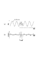
- the waveform of the beat signal is a signal having a high frequency due to interference to the waveform of the beat signal to be detected.
- the component waveform is superimposed (see FIG. 5A).
- the influence of interference (difference frequency component between the transmission wave and the interference wave) appears in the frequency band of the beat signal to be processed by the in-vehicle radar device.
- this is limited to a short period in the vicinity where the frequencies of the interfering radar waves intersect each other. For this reason, it is possible to suppress the influence of interference by shaping the waveform of the part affected by the interference, for example, by software.
- the on-vehicle radar device includes interference determination means, selection means, and frequency change means.
- the interference determination means determines the presence or absence of interference between multi-frequency CWs that are radar waves, based on a beat signal that is generated by mixing a transmission signal and a reception signal of radar waves.
- the selection unit selects either the own device or the counterpart device that is the interference partner according to the state of occurrence of the interference.
- the frequency changing unit changes the center frequency of the multi-frequency CW transmitted from the own device when the own device is selected by the selecting unit.
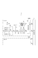
- the in-vehicle radar device 1 to which the present invention is applied includes a pair of radar sensors 3 (3R, 3L) and an integrated processing unit 5, as shown in FIG.
- the radar sensors 3 are provided at the left and right ends of a bumper provided at the rear end of the vehicle, respectively, and both have the same configuration.
- the radar sensor 3 positioned at the right end of the bumper is referred to as a right sensor 3R
- the radar sensor 3 positioned at the left end of the bumper is referred to as a left sensor 3L.
- the right sensor 3R is set so that an area extending from the right side of the vehicle to the right rear is an exploration range
- the left sensor 3L is set to an area extending from the left side of the vehicle to the left rear.
- the radar sensor 3 includes a voltage controlled oscillator 10 with a PLL (Phase Locked Loop) circuit, a distributor 14, a transmission antenna 16, a reception antenna unit 20, a reception switch 22, a mixer 24, an amplifier 26, and an LPF (LPF). Low Pass Filter 27, A / D (analog-digital) converter 28, and signal processing unit 30 are provided.
- PLL Phase Locked Loop
- the voltage-controlled oscillator 10 with a PLL circuit is a well-known one including a reference signal oscillator, a frequency divider, a phase comparator, a voltage-controlled oscillator, and the like, and controls signal processing by controlling the frequency division number in the frequency divider.
- a millimeter wave band signal having a frequency according to the frequency control signal Cf from the unit 30 is generated.
- the distributor 14 distributes the power of the output of the voltage controlled oscillator 10 with a PLL circuit to the transmission signal Ss and the local signal L, and supplies the transmission signal Ss to the transmission antenna 16 and the local signal L to the mixer 24.
- the transmission antenna 16 radiates a radar wave according to the transmission signal Ss.
- the receiving antenna unit 20 includes N antennas that receive radar waves.
- the reception switch 22 selects any one of the antennas constituting the reception antenna unit 20 in order, and supplies the reception signal Sr from the selected antenna to the mixer 24.
- the mixer 24 mixes the local signal L with the received signal Sr to generate a beat signal B and supplies it to the amplifier 26.
- the amplifier 26 amplifies the beat signal B and supplies it to the LPF 27.
- the LPF 27 uses the sampling frequency of the A / D converter 28 as fs, removes a signal component having a frequency of fs / 2 or more from the beat signal B amplified by the amplifier 26, and supplies the signal to the A / D converter 28. .
- the A / D converter 28 samples the output of the LPF 27 at the sampling frequency fs, converts it into digital data (hereinafter referred to as “sampling data”) Db, and supplies the digital data to the signal processing unit 30.
- the signal processing unit 30 is configured around a well-known microcomputer including a CPU, a ROM, and a RAM. Further, the signal processing such as fast Fourier transform (FFT) processing is performed on the data taken in via the A / D converter 28. Is provided.
- the signal processing unit 30 executes at least transmission processing and target detection processing.
- a desired radar wave is transmitted by generating a frequency control signal Cf according to a predetermined schedule in accordance with the timing signal TCi (TC1 for the right sensor 3R, TC2 for the left sensor) from the integrated processing unit 5.
- the target detection process generates information (target information) TG related to the target reflecting the radar wave based on the sampling data Db obtained during the transmission period of the radar wave, and integrates the target information TG. 5 is supplied.
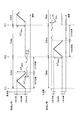
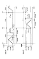
- the first half operates as an FMCW radar
- the second half operates as a two-frequency CW (2FCW) radar.
- the frequency band of 200 MHz (24.05 GHz to 24.25 GHz) defined by the Radio Law is applied to the lower CW band of 10 MHz width (24.05 GHz to 24.06 GHz) and 180 MHz width (24.06 to 24.24 GHz).
- the FMCW band is assigned to FMCW modulation (common to the right sensor 3R and the left sensor 3L).
- the lower CW band is assigned to 2FCW modulation of the right sensor 3R.
- the upper CW band is assigned to 2FCW modulation of the left sensor 3L.
- FMCW modulation an FMCW having a modulation width ⁇ F FMCW of 180 MHz is generated using the entire frequency region of the FMCW band.
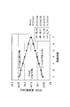
- R_F0 and R_F1 two types of frequencies used in the right sensor 3R
- R_F1 and R_F1 two types of frequencies used in the right sensor 3R
- RF Two types of frequencies used in the left sensor 3L
- L_F0 and L_F1 Two types of frequencies used in the left sensor 3L are represented by L_F0 and L_F1, and their center frequencies are represented by LF.
- the center frequency RF is set to the center frequency RF by a predetermined step frequency F STEP with the frequencies R_F0 and R_F1 set so that the center frequency RF matches the lower limit frequency of the lower CW band as the home position. It is set to be able to increase.
- the center frequency LF can be decreased by the step frequency F STEP by using the frequencies L_F0 and L_F1 set so that the center frequency LF matches the upper limit frequency of the upper CW band as the home position.
- the frequency used for 2FCW modulation is initially set to the home position.
- the step frequency F STEP is set based on the difference between the upper limit frequency of the passband and the frequency whose amplitude is sufficiently small (for example, 1/10) based on the cutoff characteristic of the LPF 27.
- the target detection process includes an FMCW target detection process that is a process based on sampling data obtained during the FMCW modulation period and a 2FCW target detection process that is a process based on sampling data obtained during the 2FCW modulation period. It is executed during a stop period in which no wave transmission / reception is performed.
- the FMCW target detection process is well-known, including countermeasures when interference with radar waves (FMCW, 2FCW) transmitted from other vehicles occurs, and thus description thereof is omitted.
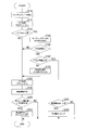
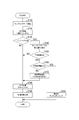
- the CPU of the signal processing unit 30 (hereinafter referred to as the signal processing unit 30) first reads the sampling data Db acquired in the 2FCW modulation period in step S110.
- the signal processing unit 30 performs frequency analysis processing (in this case, FFT processing) on the sampling data acquired for one designated channel set in advance.
- step S130 the signal processing unit 30 compares the noise floor calculated from the processing result in step S120 with the reference value of the noise floor calculated based on the processing result up to the previous processing cycle (reference It is determined whether or not the value is higher than a predetermined value set in advance. If the noise floor has not risen (S130: NO), the process proceeds to step S180, assuming that no interference has occurred. If the noise floor is rising (S130: YES), the process proceeds to step S140, assuming that interference has occurred.
- the difference frequency component in the vicinity where the transmission wave from the own apparatus (here 2FCW) intersects the frequency of the interference wave is a frequency necessary for target detection. Appears in the band (hereinafter referred to as “detection target frequency band”), and this raises the noise floor.
- detection target frequency band the band
- the interference wave is 2FCW
- the transmission wave from the own device and the interference wave use the same frequencies F0 and F1
- the difference frequency component is out of the detection target frequency band, the LPF 27 does not sufficiently remove it because the A / D converter 28 performs oversampling.
- the difference frequency component is returned to the detection target frequency band and detected as a result of the FFT processing, and the noise floor is raised. That is, by examining the noise floor, it is possible to detect the presence or absence of interference regardless of whether the interference wave is FMCW or 2FCW.
- step S140 the signal processing unit 30 calculates a change amount DV (see FIG. 5B) of the signal level of the beat signal between the sampling points based on the sampling data (see FIG. 5A).
- step S150 the signal processing unit 30 determines whether or not there is an interference section in which the absolute value
- the voltage threshold Vth is set to the lower limit value of the change amount DV detected when a noise component of 1 MHz or higher is superimposed on the beat signal.
- the signal processing unit 30 determines whether or not the length of the interference section is greater than or equal to a preset time threshold value Tth.
- This time threshold value Tth is set in advance based on the observation result of the duration in which the influence of interference appears in the detection target frequency band when the interference wave is FMCW. Specifically, the time threshold value Tth is set to a value larger than the length of the duration period.
- the interference wave is determined to be FMCW, and the process proceeds to S170.
- the interference section length is equal to or greater than the time threshold Tth (S160: YES)
- it is determined that the interference wave is 2FCW, and the process proceeds to S220.
- the signal processing unit 30 determines whether or not the interference section occurs at the start side end of the 2FCW modulation section. That is, as long as the transmission timing of the transmission wave from the own device and the transmission timing of the interference wave do not match, as shown in FIG. 6C, the interference section occurs at either the start side end or the end side end of the transmission wave. In the interference partner device, the interference section occurs at the opposite end to the own device. By using this relationship, it is possible to identify a device in which interference has occurred.
- the signal processing unit 30 sets the frequency of 2FCW to hop (change the center frequency one step away from the home position). Then, this process ends. Thus, the frequency after hopping is used in 2FCW modulation in the next operation period. If the current setting of the center frequency is already at the top, the driver may be informed so that the output of the processing result may be stopped for a certain period, or the center frequency may be set to the home position. You may make it change to.
- the signal processing unit 30 executes a waveform shaping operation for smoothing the waveform in the interference section, and proceeds to S180.
- the sampling data in the interference section is corrected so that the waveforms before and after the interference section are continuously connected. This process is executed for sampling data of all channels.
- the signal processing unit 30 performs, for each channel, on the basis of the sampling data after the waveform shaping calculation.
- Frequency analysis of the beat signal (FFT processing in this embodiment) is executed for each of the frequencies F0 and F1.
- the oversampled data may be used as it is, but down-converted data (data thinned out on the time axis) is used so that unnecessary frequency components other than the detection target frequency band are removed. It may be.
- the signal processing unit 30 In subsequent S190, the signal processing unit 30 generates target information TG including at least a distance, a speed, and an azimuth using a known method in the 2FCW radar from the processing result in S180, and outputs this to the integrated processing unit 5 Is executed, and the process proceeds to S200.
- the signal processing unit 30 determines whether the elapsed time after changing the frequency from the home position in S230 described above exceeds a preset standby time. When the elapsed time does not exceed the standby time (S200: NO), this process is terminated as it is. On the other hand, when the elapsed time exceeds the standby time (S200: YES), in S210, the signal processing unit 30 returns the settings of the frequencies F0 and F1 used in 2FCW modulation to the home position, and ends this processing. To do.
- the standby time may be set longer than the interference duration in the situation where the interference state continues most of the situations where interference occurs. For example, an average time required to move to some extent after starting the engine in a parking lot or the like may be used, and in this case, it may be set to about 8 seconds.
- the in-vehicle radar device 1 detects the presence or absence of interference by increasing the noise floor, and identifies whether the interference wave is FMCW or 2FCW from the length of the interference section. If the interference wave is FMCW, the sampling data is corrected so that the waveform of the beat signal corresponding to the interference section is shaped, and FFT processing and target information generation are performed using the corrected data. If the interference wave is 2FCW, the sampling data is discarded, and the frequency of 2FCW is hopped only to one of the own apparatus and the counterpart apparatus specified from the interference state, so that the 2FCW period of the next operation period In addition, the occurrence of interference again is suppressed.
- the center frequency of 2FCW is regularly changed only on one of the own device and the counterpart device.
- the second embodiment is different from the first embodiment in that the center frequency of 2FCW is randomly changed in both the own device and the counterpart device.
- the entire 200 MHz width (24.05 GHz to 24.25 GHz) defined by the Radio Law is set as an allowable frequency band, and is randomly selected from 10,000 kinds of center frequencies set in 20 kHz steps in this allowable frequency band. Select one to use.
- the lower limit frequency of the allowable frequency band is assigned as the initial value of the center frequency used in the 2FCW modulation of the right sensor 3R
- the upper limit of the allowable frequency band is set as the initial value of the center frequency used in the 2FCW modulation of the left sensor 3L. Assign a frequency.
- the initial value of the center frequency is not limited to this, and may be assigned at random from the beginning.
- the signal processing unit 30 randomly hops the frequency of 2FCW.
- the center frequency is set to be changed by randomly selecting any one of 10000 types of settings in the allowable frequency band, and the process is terminated.
- the integration processing unit 5 is provided separately from the signal processing unit 30, but one signal processing unit 30 of the right sensor 3 ⁇ / b> R and the left sensor 3 ⁇ / b> L also serves as the integration processing unit 5. It may be configured.
- the signal processing unit 30 may be separated from both the sensors 3R and 3L and configured integrally with the integrated processing unit 5.
- the frequency may be determined according to which of the transmission wave and the interference wave is higher.
- the standby time when a center frequency of 2FCW is hopped, a fixed value is used as the standby time that is the time to the home position frequency, but it may be varied depending on the situation.
- the standby time may be variably set according to the host vehicle speed. In this case, specifically, it is conceivable to set 8 seconds when the host vehicle speed is less than 10 km / h, and 4 seconds when the vehicle speed is 10 km / h or more.
- the standby time may be variably set according to the transmission gear setting. In this case, specifically, it is conceivable that the gear setting is set to 4 seconds when moving forward and set to 8 seconds when moving backward. That is, in a situation where the average time required for eliminating the interference is longer, the standby time may be set longer, and vice versa.
- Each component of the present invention is conceptual and is not limited to the above embodiment.
- the functions of one component may be distributed to a plurality of components, or the functions of a plurality of components may be integrated into one component.
- at least a part of the configuration of the above embodiment may be replaced with a known configuration having the same function.
- at least a part of the configuration of the above embodiment may be added to or replaced with the configuration of the other embodiment.
- the on-vehicle radar device includes interference determination means, selection means, and frequency change means.
- the interference determination means determines the presence or absence of interference between multi-frequency CWs that are radar waves, based on a beat signal that is generated by mixing a transmission signal and a reception signal of radar waves.
- the selection unit selects either the own device or the counterpart device that is the interference partner according to the state of occurrence of the interference.
- the frequency changing unit changes the center frequency of the multi-frequency CW transmitted from the own device when the own device is selected by the selecting unit.
- the center frequency of the multi-frequency CW is changed only on one of the own device and the counterpart device causing the interference, the frequency of the noise component generated by the interference is separated from the signal component. Can be easily converted to a sufficiently high frequency band. That is, even if interference between multi-frequency CWs occurs, such a countermeasure is taken, so that the influence of the interference can be removed.
- the on-vehicle radar device of the present embodiment may be configured by interference determining means and frequency random changing means.
- the interference determination means determines the presence / absence of interference between multi-frequency CWs, which are one of the radar waves, based on the beat signal generated by mixing the transmission signal and the reception signal of the radar wave.
- the frequency random changing means randomly changes the center frequency of the multi-frequency CW transmitted from the own apparatus within a preset allowable frequency range when the interference determining means determines that there is interference.
- the center frequency of the multi-frequency CW is randomly changed in both the own device and the counterpart device causing the interference.
- the frequency of the noise component generated by the interference is converted to a sufficiently high frequency band that can be easily separated from the signal component. That is, even if interference between multi-frequency CWs occurs, such a countermeasure is taken, so that the influence of the interference can be removed.
- the present invention is realized in various forms such as various systems including the on-vehicle radar device as components, a program for causing a computer to function as the on-vehicle radar device, and an interference avoidance method. be able to.
Landscapes
- Engineering & Computer Science (AREA)
- Radar, Positioning & Navigation (AREA)
- Remote Sensing (AREA)
- Computer Networks & Wireless Communication (AREA)
- Physics & Mathematics (AREA)
- General Physics & Mathematics (AREA)
- Electromagnetism (AREA)
- Signal Processing (AREA)
- Radar Systems Or Details Thereof (AREA)
Abstract
The vehicle-mounted radar device according to the present invention is provided with an interference determination means, a selection means, and a frequency changing means. The interference determination means determines the presence of interference between multifrequency CW radar waves on the basis of a beat signal generated by mixing of radar wave transmission signals and reception signals. The selection means selects a host device or an other-party device which is party to interference in accordance with the status of interference when the interference determination means determines that interference is present. The frequency changing means changes the center frequency of the multifrequency CW transmitted from the host device when the host device is selected by the selection means.
Description
本発明は、車両に搭載されレーダ波を用いて物標検出等を行う車載レーダ装置に関する。
The present invention relates to an on-vehicle radar device that is mounted on a vehicle and detects a target using a radar wave.
車載レーダでは、自車両の車載レーダから送出されたレーダ波の反射波だけでなく、対向車や併走車など自車両の近傍に存在する他車両の車載レーダから送出されたレーダ波を受信してしまうことがある。これにより、いわゆる車載レーダ同士の干渉が発生する場合がある。
In-vehicle radar receives not only the reflected wave of the radar wave transmitted from the in-vehicle radar of the own vehicle, but also the radar wave transmitted from the in-vehicle radar of another vehicle in the vicinity of the own vehicle such as an oncoming vehicle or a parallel vehicle. May end up. As a result, interference between so-called in-vehicle radars may occur.
レーダ波としてFMCWを使用している場合、他装置から送信されたFMCWや多周波CWとの干渉が発生すると、ビート信号の波形は、検出すべきビート信号の波形に、干渉による周波数の高い信号成分の波形が重畳されたものとなる(図5(a)参照)。
When FMCW is used as a radar wave, if interference with FMCW or multi-frequency CW transmitted from another device occurs, the waveform of the beat signal is a signal having a high frequency due to interference to the waveform of the beat signal to be detected. The component waveform is superimposed (see FIG. 5A).
この点に着目し、ビート信号の信号レベルが極大または極小となる極点を抽出し、抽出した極点の出現タイミングが非周期的であれば、他の車載レーダ装置との干渉が発生していると判定する技術が知られている(例えば、特許文献1参照)。
Focusing on this point, extracting the extreme point where the signal level of the beat signal becomes maximum or minimum, and if the appearance timing of the extracted extreme point is aperiodic, it means that interference with other in-vehicle radar devices has occurred A technique for determining is known (see, for example, Patent Document 1).
ところで、送信波がFMCWで干渉波がFMCWまたはCWである場合、車載レーダ装置の処理対象となるビート信号の周波数帯域内に、干渉の影響(送信波と干渉波の差周波数成分)が現れることがある。これは、図6(a)および(b)に示すように、干渉し合うレーダ波の周波数が互いに交差する近傍の短期間に限られる。このため、干渉の影響を受けている部分の波形を、例えば、ソフトウェア的に整形することによって、干渉の影響を抑制することが可能である。
By the way, when the transmission wave is FMCW and the interference wave is FMCW or CW, the influence of interference (difference frequency component between the transmission wave and the interference wave) appears in the frequency band of the beat signal to be processed by the in-vehicle radar device. There is. As shown in FIGS. 6A and 6B, this is limited to a short period in the vicinity where the frequencies of the interfering radar waves intersect each other. For this reason, it is possible to suppress the influence of interference by shaping the waveform of the part affected by the interference, for example, by software.
しかし、自装置がレーダ波として多周波CWを使用している場合、他装置から送信されたCW波と干渉(多周波CW同士の干渉)すると、図6(b)に示すように、両者の送信期間が互いに重なり合っている間、干渉の影響が現れ続けることになる。このため、送信期間の重なり具合によっては、上述のソフトウェア的に波形整形する対処法を採用することが困難な場合がある。
However, when the own device uses a multi-frequency CW as a radar wave, interference with a CW wave transmitted from another device (interference between multi-frequency CWs), as shown in FIG. While the transmission periods overlap each other, the effects of interference will continue to appear. For this reason, depending on how the transmission periods overlap, it may be difficult to employ the above-described method of waveform shaping in software.
一実施形態は、多周波CWレーダ同士の干渉に対処する車載レーダ装置を提供する。
一実施形態の車載レーダ装置は、干渉判定手段と、選択手段と、周波数変更手段とを備える。干渉判定手段は、レーダ波の送信信号と受信信号とを混合することで生成されるビート信号に基づいて、レーダ波である多周波CW同士の干渉の有無を判定する。選択手段は、干渉判定手段により干渉ありと判定された場合に、干渉の発生状況に従って、自装置または干渉相手である相手側装置のいずれかを選択する。周波数変更手段は、選択手段により前記自装置が選択された場合に、前記自装置から送信される多周波CWの中心周波数を変更する。 One embodiment provides an in-vehicle radar device that copes with interference between multi-frequency CW radars.
The on-vehicle radar device according to an embodiment includes interference determination means, selection means, and frequency change means. The interference determination means determines the presence or absence of interference between multi-frequency CWs that are radar waves, based on a beat signal that is generated by mixing a transmission signal and a reception signal of radar waves. When the interference determination unit determines that there is interference, the selection unit selects either the own device or the counterpart device that is the interference partner according to the state of occurrence of the interference. The frequency changing unit changes the center frequency of the multi-frequency CW transmitted from the own device when the own device is selected by the selecting unit.
以下に本発明の実施形態を図面と共に説明する。
[第1実施形態]
<全体構成>
本発明が適用された車載レーダ装置1は、図1に示すように、一対のレーダセンサ3(3R,3L)と統合処理部5とを備える。 Embodiments of the present invention will be described below with reference to the drawings.
[First Embodiment]
<Overall configuration>
The in-vehicle radar device 1 to which the present invention is applied includes a pair of radar sensors 3 (3R, 3L) and an integrated processing unit 5, as shown in FIG.
[第1実施形態]
<全体構成>
本発明が適用された車載レーダ装置1は、図1に示すように、一対のレーダセンサ3(3R,3L)と統合処理部5とを備える。 Embodiments of the present invention will be described below with reference to the drawings.
[First Embodiment]
<Overall configuration>
The in-
<レーダセンサ>
レーダセンサ3は、車両後端に設けられたバンパの左右両端にそれぞれ設けられ、いずれも同様の構成を有する。以下では、特に識別する必要がある場合は、バンパの右端に位置するレーダセンサ3を右センサ3R、バンパの左端に位置するレーダセンサ3を左センサ3Lと呼ぶ。右センサ3Rは、車両の右側方から右後方に渡る領域を探査範囲とし、左センサ3Lは車両の左側方から左後方に渡る領域を探査範囲とするように設定されている。 <Radar sensor>
Theradar sensors 3 are provided at the left and right ends of a bumper provided at the rear end of the vehicle, respectively, and both have the same configuration. Hereinafter, when it is particularly necessary to identify, the radar sensor 3 positioned at the right end of the bumper is referred to as a right sensor 3R, and the radar sensor 3 positioned at the left end of the bumper is referred to as a left sensor 3L. The right sensor 3R is set so that an area extending from the right side of the vehicle to the right rear is an exploration range, and the left sensor 3L is set to an area extending from the left side of the vehicle to the left rear.
レーダセンサ3は、車両後端に設けられたバンパの左右両端にそれぞれ設けられ、いずれも同様の構成を有する。以下では、特に識別する必要がある場合は、バンパの右端に位置するレーダセンサ3を右センサ3R、バンパの左端に位置するレーダセンサ3を左センサ3Lと呼ぶ。右センサ3Rは、車両の右側方から右後方に渡る領域を探査範囲とし、左センサ3Lは車両の左側方から左後方に渡る領域を探査範囲とするように設定されている。 <Radar sensor>
The
レーダセンサ3は、PLL(Phase Locked Loop)回路付き電圧制御発振器10と、分配器14と、送信アンテナ16と、受信アンテナ部20と、受信スイッチ22と、ミキサ24と、増幅器26と、LPF(Low Pass Filter)27と、A/D(アナログ-デジタル)変換器28と、信号処理部30とを備える。
The radar sensor 3 includes a voltage controlled oscillator 10 with a PLL (Phase Locked Loop) circuit, a distributor 14, a transmission antenna 16, a reception antenna unit 20, a reception switch 22, a mixer 24, an amplifier 26, and an LPF (LPF). Low Pass Filter 27, A / D (analog-digital) converter 28, and signal processing unit 30 are provided.
PLL回路付き電圧制御発振器10は、基準信号発振器、分周器、位相比較器、電圧制御発振器等を備えた周知のものであり、分周器での分周数を制御することによって、信号処理部30からの周波数制御信号Cfに従った周波数を有するミリ波帯の信号を生成する。分配器14は、PLL回路付き電圧制御発振器10の出力を送信信号Ssとローカル信号Lとに電力分配し、送信信号Ssを送信アンテナ16に、ローカル信号Lをミキサ24に供給する。送信アンテナ16は、送信信号Ssに従ってレーダ波を放射する。
The voltage-controlled oscillator 10 with a PLL circuit is a well-known one including a reference signal oscillator, a frequency divider, a phase comparator, a voltage-controlled oscillator, and the like, and controls signal processing by controlling the frequency division number in the frequency divider. A millimeter wave band signal having a frequency according to the frequency control signal Cf from the unit 30 is generated. The distributor 14 distributes the power of the output of the voltage controlled oscillator 10 with a PLL circuit to the transmission signal Ss and the local signal L, and supplies the transmission signal Ss to the transmission antenna 16 and the local signal L to the mixer 24. The transmission antenna 16 radiates a radar wave according to the transmission signal Ss.
受信アンテナ部20は、レーダ波を受信するN個のアンテナからなる。受信スイッチ22は、受信アンテナ部20を構成するアンテナのいずれか一つを順番に選択し、選択されたアンテナからの受信信号Srをミキサ24に供給する。ミキサ24は、受信信号Srにローカル信号Lを混合してビート信号Bを生成して増幅器26に供給する。増幅器26はビート信号Bを増幅してLPF27に供給する。LPF27は、A/D変換器28でのサンプリング周波数をfsとして、増幅器26により増幅されたビート信号Bからfs/2以上の周波数を有する信号成分を除去してA/D変換器28に供給する。A/D変換器28は、LPF27の出力をサンプリング周波数fsでサンプリングしデジタルデータ(以下「サンプリングデータ」という)Dbに変換して、信号処理部30に供給する。
The receiving antenna unit 20 includes N antennas that receive radar waves. The reception switch 22 selects any one of the antennas constituting the reception antenna unit 20 in order, and supplies the reception signal Sr from the selected antenna to the mixer 24. The mixer 24 mixes the local signal L with the received signal Sr to generate a beat signal B and supplies it to the amplifier 26. The amplifier 26 amplifies the beat signal B and supplies it to the LPF 27. The LPF 27 uses the sampling frequency of the A / D converter 28 as fs, removes a signal component having a frequency of fs / 2 or more from the beat signal B amplified by the amplifier 26, and supplies the signal to the A / D converter 28. . The A / D converter 28 samples the output of the LPF 27 at the sampling frequency fs, converts it into digital data (hereinafter referred to as “sampling data”) Db, and supplies the digital data to the signal processing unit 30.
なお、受信アンテナ部20を構成するN個のアンテナを、それぞれチャンネルch1~chNに割り当てるものとする。1チャンネル当たりのサンプリング周波数をfpsとして、A/D変換器28のサンプリング周波数は、fs=N×fpsに設定されている。また、1チャンネル当たりのサンプリング周波数fpsは、ターゲットの検出範囲に対応するビート信号Bの周波数領域を検出周波数領域として、この検出周波数領域の上限周波数(最大ビート周波数)の2倍より大きな値(好ましくは上限周波数の4倍以上)に設定され、いわゆるオーバーサンプリングをするように設定されている。
Note that the N antennas constituting the receiving antenna unit 20 are assigned to the channels ch1 to chN, respectively. The sampling frequency of the A / D converter 28 is set to fs = N × fps, where the sampling frequency per channel is fps. Further, the sampling frequency fps per channel is a value larger than twice the upper limit frequency (maximum beat frequency) of the detection frequency region with the frequency region of the beat signal B corresponding to the detection range of the target as the detection frequency region (preferably Is set to 4 or more times the upper limit frequency), and so-called oversampling is set.
信号処理部30は、CPU,ROM,RAMからなる周知のマイクロコンピュータを中心に構成され、更に、A/D変換器28を介して取り込んだデータについて、高速フーリエ変換(FFT)処理等の信号処理を実行する演算処理装置を備えている。信号処理部30は、少なくとも送信処理と物標検出処理を実行する。送信処理は、統合処理部5からのタイミング信号TCi(右センサ3RにはTC1,左センサにはTC2)に従い、予め定められたスケジュールに従って周波数制御信号Cfを生成することによって所望のレーダ波を送信する。物標検出処理は、レーダ波の送信期間中に得られたサンプリングデータDbに基づいて、レーダ波を反射したターゲットに関する情報(物標情報)TGを生成し、その物標情報TGを統合処理部5に供給する。
The signal processing unit 30 is configured around a well-known microcomputer including a CPU, a ROM, and a RAM. Further, the signal processing such as fast Fourier transform (FFT) processing is performed on the data taken in via the A / D converter 28. Is provided. The signal processing unit 30 executes at least transmission processing and target detection processing. In the transmission process, a desired radar wave is transmitted by generating a frequency control signal Cf according to a predetermined schedule in accordance with the timing signal TCi (TC1 for the right sensor 3R, TC2 for the left sensor) from the integrated processing unit 5. To do. The target detection process generates information (target information) TG related to the target reflecting the radar wave based on the sampling data Db obtained during the transmission period of the radar wave, and integrates the target information TG. 5 is supplied.
以下、信号処理部30が実行する送信処理、物標検出処理について説明する。
<送信処理>
送信処理では、図2に示すように、タイミング信号TCiが入力されると、予め設定された一定の動作期間(Active)の間だけレーダ波を送信するように周波数制御信号Cfを生成する。但し、タイミング信号TCiは、右センサ3Rと左センサ3Lに交互に入力され、常にいずれか一方が動作期間となり、他方が休止期間(Sleep)となるように制御される。 Hereinafter, transmission processing and target detection processing executed by thesignal processing unit 30 will be described.
<Transmission processing>
In the transmission process, as shown in FIG. 2, when the timing signal TCi is input, the frequency control signal Cf is generated so that the radar wave is transmitted only during a predetermined constant operation period (Active). However, the timing signal TCi is alternately input to theright sensor 3R and the left sensor 3L, and is always controlled so that one of them is an operation period and the other is a rest period (Sleep).
<送信処理>
送信処理では、図2に示すように、タイミング信号TCiが入力されると、予め設定された一定の動作期間(Active)の間だけレーダ波を送信するように周波数制御信号Cfを生成する。但し、タイミング信号TCiは、右センサ3Rと左センサ3Lに交互に入力され、常にいずれか一方が動作期間となり、他方が休止期間(Sleep)となるように制御される。 Hereinafter, transmission processing and target detection processing executed by the
<Transmission processing>
In the transmission process, as shown in FIG. 2, when the timing signal TCi is input, the frequency control signal Cf is generated so that the radar wave is transmitted only during a predetermined constant operation period (Active). However, the timing signal TCi is alternately input to the
動作期間中は、その前半はFMCWレーダとして動作し、後半は2周波CW(2FCW)レーダとして動作する。但し、電波法で定められた200MHz幅(24.05GHz~24.25GHz)の周波数帯を、10MHz幅(24.05GHz~24.06GHz)の下部CW帯、180MHz幅(24.06~24.24GHz)のFMCW帯、10MHz幅(24.24GHzから24.25GHz)の上部CW帯からなる三つの周波数帯に分けている。FMCW帯をFMCW変調(右センサ3Rおよび左センサ3L共通)に割り当てている。下部CW帯を右センサ3Rの2FCW変調に割り当てている。上部CW帯を左センサ3Lの2FCW変調に割り当てている。
During the operation period, the first half operates as an FMCW radar, and the second half operates as a two-frequency CW (2FCW) radar. However, the frequency band of 200 MHz (24.05 GHz to 24.25 GHz) defined by the Radio Law is applied to the lower CW band of 10 MHz width (24.05 GHz to 24.06 GHz) and 180 MHz width (24.06 to 24.24 GHz). ) FMCW band and 10 MHz width (24.24 GHz to 24.25 GHz) of the upper CW band. The FMCW band is assigned to FMCW modulation (common to the right sensor 3R and the left sensor 3L). The lower CW band is assigned to 2FCW modulation of the right sensor 3R. The upper CW band is assigned to 2FCW modulation of the left sensor 3L.
FMCW変調では、FMCW帯の全周波数領域を使って変調幅ΔFFMCWが180MHzのFMCWを生成する。
2FCW変調では、周波数差がΔF2FCW=1MHzに設定された2種類の周波数F0,F1(=F0+ΔF2FCW)を使用する。以下、右センサ3Rで使用する2種類の周波数をR_F0,R_F1、その中心周波数をRFで表す。左センサ3Lで使用する2種類の周波数をL_F0,L_F1、その中心周波数をLFで表す。図3に示すように、右センサ3Rでは、中心周波数RFが下部CW帯の下限周波数と一致するように設定された周波数R_F0,R_F1をホームポジションとして、所定のステップ周波数FSTEPずつ、中心周波数RFを増加させることができるように設定されている。一方、左センサ3Lでは、中心周波数LFが上部CW帯の上限周波数と一致するように設定された周波数L_F0,L_F1をホームポジションとして、ステップ周波数FSTEPずつ、中心周波数LFを低下させることができるように設定されている。ここでは、ステップ周波数はFSTEP=15MHz、周波数の切替段数はホームポジションを含めて7段に設定されている。 In FMCW modulation, an FMCW having a modulation width ΔF FMCW of 180 MHz is generated using the entire frequency region of the FMCW band.
In 2FCW modulation, two types of frequencies F0 and F1 (= F0 + ΔF2FCW ) having a frequency difference set to ΔF 2FCW = 1 MHz are used. Hereinafter, two types of frequencies used in theright sensor 3R are represented by R_F0 and R_F1, and their center frequencies are represented by RF. Two types of frequencies used in the left sensor 3L are represented by L_F0 and L_F1, and their center frequencies are represented by LF. As shown in FIG. 3, in the right sensor 3R, the center frequency RF is set to the center frequency RF by a predetermined step frequency F STEP with the frequencies R_F0 and R_F1 set so that the center frequency RF matches the lower limit frequency of the lower CW band as the home position. It is set to be able to increase. On the other hand, in the left sensor 3L, the center frequency LF can be decreased by the step frequency F STEP by using the frequencies L_F0 and L_F1 set so that the center frequency LF matches the upper limit frequency of the upper CW band as the home position. Is set to Here, the step frequency is set to F STEP = 15 MHz, and the frequency switching stage number is set to 7 stages including the home position.
2FCW変調では、周波数差がΔF2FCW=1MHzに設定された2種類の周波数F0,F1(=F0+ΔF2FCW)を使用する。以下、右センサ3Rで使用する2種類の周波数をR_F0,R_F1、その中心周波数をRFで表す。左センサ3Lで使用する2種類の周波数をL_F0,L_F1、その中心周波数をLFで表す。図3に示すように、右センサ3Rでは、中心周波数RFが下部CW帯の下限周波数と一致するように設定された周波数R_F0,R_F1をホームポジションとして、所定のステップ周波数FSTEPずつ、中心周波数RFを増加させることができるように設定されている。一方、左センサ3Lでは、中心周波数LFが上部CW帯の上限周波数と一致するように設定された周波数L_F0,L_F1をホームポジションとして、ステップ周波数FSTEPずつ、中心周波数LFを低下させることができるように設定されている。ここでは、ステップ周波数はFSTEP=15MHz、周波数の切替段数はホームポジションを含めて7段に設定されている。 In FMCW modulation, an FMCW having a modulation width ΔF FMCW of 180 MHz is generated using the entire frequency region of the FMCW band.
In 2FCW modulation, two types of frequencies F0 and F1 (= F0 + ΔF2FCW ) having a frequency difference set to ΔF 2FCW = 1 MHz are used. Hereinafter, two types of frequencies used in the
なお、レーダセンサ3の起動時に、2FCW変調で使用する周波数は、ホームポジションに初期設定される。また、ステップ周波数FSTEPは、LPF27のカットオフ特性に基づき、通過帯域の上限周波数と、その上限周波数に対して振幅が十分に小さく(例えば1/10)なる周波数との差に基づいて設定される。
When the radar sensor 3 is activated, the frequency used for 2FCW modulation is initially set to the home position. The step frequency F STEP is set based on the difference between the upper limit frequency of the passband and the frequency whose amplitude is sufficiently small (for example, 1/10) based on the cutoff characteristic of the LPF 27. The
<物標検出処理>
物標検出処理は、FMCW変調期間に得られたサンプリングデータに基づく処理であるFMCW物標検出処理と2FCW変調期間に得られたサンプリングデータに基づく処理である2FCW物標検出処理とからなり、レーダ波の送受信を行わない停止期間中に実行される。FMCW物標検出処理は、他車両から送出されたレーダ波(FMCW,2FCW)との干渉が生じた場合の対処も含めて周知のものであるため説明を省略する。 <Target detection processing>
The target detection process includes an FMCW target detection process that is a process based on sampling data obtained during the FMCW modulation period and a 2FCW target detection process that is a process based on sampling data obtained during the 2FCW modulation period. It is executed during a stop period in which no wave transmission / reception is performed. The FMCW target detection process is well-known, including countermeasures when interference with radar waves (FMCW, 2FCW) transmitted from other vehicles occurs, and thus description thereof is omitted.
以下では、2FCW物標検出処理を図4に示すフローチャートに沿って説明する。
信号処理部30のCPU(以下、信号処理部30と称す)は、本処理が起動すると、まずステップS110では、2FCW変調期間に取得したサンプリングデータDbを読み出す。続くステップS120では、信号処理部30は、予め設定された一つの指定チャンネルについて取得されたサンプリングデータに対して周波数解析処理(ここではFFT処理)を実行する。 Below, 2FCW target detection processing is demonstrated along the flowchart shown in FIG.
When this processing is activated, the CPU of the signal processing unit 30 (hereinafter referred to as the signal processing unit 30) first reads the sampling data Db acquired in the 2FCW modulation period in step S110. In subsequent step S120, thesignal processing unit 30 performs frequency analysis processing (in this case, FFT processing) on the sampling data acquired for one designated channel set in advance.
信号処理部30のCPU(以下、信号処理部30と称す)は、本処理が起動すると、まずステップS110では、2FCW変調期間に取得したサンプリングデータDbを読み出す。続くステップS120では、信号処理部30は、予め設定された一つの指定チャンネルについて取得されたサンプリングデータに対して周波数解析処理(ここではFFT処理)を実行する。 Below, 2FCW target detection processing is demonstrated along the flowchart shown in FIG.
When this processing is activated, the CPU of the signal processing unit 30 (hereinafter referred to as the signal processing unit 30) first reads the sampling data Db acquired in the 2FCW modulation period in step S110. In subsequent step S120, the
続くステップS130では、信号処理部30は、ステップS120での処理結果から算出されるノイズフロアが、前回の処理サイクルまでの処理結果に基づいて算出されるノイズフロアの基準値と比較して(基準値に対して)、予め設定された所定値以上上昇しているか否かを判断する。ノイズフロアが上昇していない場合(S130:NO)は、干渉が生じていないものとして、処理はステップS180に進む。ノイズフロアが上昇している場合(S130:YES)は、干渉が生じているものとして、処理はステップS140に進む。
In subsequent step S130, the signal processing unit 30 compares the noise floor calculated from the processing result in step S120 with the reference value of the noise floor calculated based on the processing result up to the previous processing cycle (reference It is determined whether or not the value is higher than a predetermined value set in advance. If the noise floor has not risen (S130: NO), the process proceeds to step S180, assuming that no interference has occurred. If the noise floor is rising (S130: YES), the process proceeds to step S140, assuming that interference has occurred.
つまり、干渉波がFMCWの場合、自装置からの送信波(ここでは2FCW)と干渉波の周波数が交差する付近の差周波数成分(図6(b)参照)が、ターゲットの検出に必要な周波数帯(以下「検出対象周波数帯」という)に現れ、これがノイズフロアを上昇させる。一方、干渉波が2FCWの場合、自装置からの送信波と干渉波が同じ周波数F0,F1を使用していれば、両装置の送信タイミングの違いから、2FCWの差周波数ΔF2FCW(=F1-F0)のノイズが現れる。この差周波数成分は、検出対象周波数帯からは外れているものの、A/D変換器28がオーバーサンプリングを行っていることにより、LPF27では十分に除去されない。このため、差周波数成分は、FFT処理の結果、検出対象周波数帯に折り返され検出され、ノイズフロアを上昇させる。つまり、ノイズフロアを調べることにより、干渉波がFMCWか2FCWかによらず干渉の有無を検出することができる。
That is, when the interference wave is FMCW, the difference frequency component (see FIG. 6B) in the vicinity where the transmission wave from the own apparatus (here 2FCW) intersects the frequency of the interference wave is a frequency necessary for target detection. Appears in the band (hereinafter referred to as “detection target frequency band”), and this raises the noise floor. On the other hand, when the interference wave is 2FCW, if the transmission wave from the own device and the interference wave use the same frequencies F0 and F1, the difference frequency ΔF 2FCW (= F1- F0) appears. Although the difference frequency component is out of the detection target frequency band, the LPF 27 does not sufficiently remove it because the A / D converter 28 performs oversampling. For this reason, the difference frequency component is returned to the detection target frequency band and detected as a result of the FFT processing, and the noise floor is raised. That is, by examining the noise floor, it is possible to detect the presence or absence of interference regardless of whether the interference wave is FMCW or 2FCW.
ステップS140では、信号処理部30は、サンプリングデータ(図5(a)参照)に基づいて、サンプリング点間のビート信号の信号レベルの変化量DV(図5(b)参照)を算出する。続くS150では、信号処理部30は、変化量の絶対値|DV|が予め設定された電圧閾値Vth以上となる干渉区間が存在するか否かを判断する。この電圧閾値Vthは、ビート信号に1MHz以上のノイズ成分が重畳されている場合に検出される変化量DVの下限値に設定される。
In step S140, the signal processing unit 30 calculates a change amount DV (see FIG. 5B) of the signal level of the beat signal between the sampling points based on the sampling data (see FIG. 5A). In subsequent S150, the signal processing unit 30 determines whether or not there is an interference section in which the absolute value | DV | of the amount of change is equal to or greater than a preset voltage threshold Vth. The voltage threshold Vth is set to the lower limit value of the change amount DV detected when a noise component of 1 MHz or higher is superimposed on the beat signal.
干渉区間が存在しない場合(S150:NO)は、対処が必要な程度の干渉は発生していないものとして、処理はS180に進む。干渉区間が存在する場合(S150:YES)は干渉への対処が必要であるものとして、処理はS160に進む。
If the interference section does not exist (S150: NO), it is assumed that there is no interference that needs to be dealt with, and the process proceeds to S180. If an interference section exists (S150: YES), it is assumed that it is necessary to deal with the interference, and the process proceeds to S160.
S160では、信号処理部30は、干渉区間の長さが予め設定された時間閾値Tth以上であるか否かを判断する。この時間閾値Tthは、干渉波がFMCWである場合に、検出対象周波数帯に干渉の影響が現れる継続期間の観測結果に基づいて予め設定されたものを用いる。具体的には、時間閾値Tthは、その継続期間の長さより大きな値に設定される。
In S160, the signal processing unit 30 determines whether or not the length of the interference section is greater than or equal to a preset time threshold value Tth. This time threshold value Tth is set in advance based on the observation result of the duration in which the influence of interference appears in the detection target frequency band when the interference wave is FMCW. Specifically, the time threshold value Tth is set to a value larger than the length of the duration period.
干渉区間長が時間閾値Tthより小さい場合(S160:NO)、干渉波はFMCWであると判断して、処理はS170に進む。一方、干渉区間長が時間閾値Tth以上の場合(S160:YES)、干渉波は2FCWであると判断して、処理はS220に進む。
If the interference section length is smaller than the time threshold Tth (S160: NO), the interference wave is determined to be FMCW, and the process proceeds to S170. On the other hand, when the interference section length is equal to or greater than the time threshold Tth (S160: YES), it is determined that the interference wave is 2FCW, and the process proceeds to S220.
S220では、信号処理部30は、干渉区間が2FCW変調区間の開始側端で発生しているか否かを判断する。つまり、自装置からの送信波と干渉波の送信タイミングが一致しない限り、図6(c)に示すように、干渉区間は、送信波の開始側端または終了側端のいずれかで発生する。干渉相手の装置では、干渉区間は、自装置とは反対側端で発生する。この関係を利用することにより干渉が発生している装置を特定することが可能となる。
In S220, the signal processing unit 30 determines whether or not the interference section occurs at the start side end of the 2FCW modulation section. That is, as long as the transmission timing of the transmission wave from the own device and the transmission timing of the interference wave do not match, as shown in FIG. 6C, the interference section occurs at either the start side end or the end side end of the transmission wave. In the interference partner device, the interference section occurs at the opposite end to the own device. By using this relationship, it is possible to identify a device in which interference has occurred.
干渉区間が2FCW変調区間の終了側端で発生している場合(S220:NO)は、そのまま本処理を終了する。開始側端で発生している場合(S220:YES)は、S230にて、信号処理部30は、2FCWの周波数をホッピング(中心周波数をホームポジションから遠ざかる方向に一段階変化させる)する設定をして、本処理を終了する。これにより、次回の動作期間の2FCW変調では、ホッピング後の周波数が用いられることになる。なお、中心周波数の現設定が、既に最上段になっている場合は、その旨をドライバに報知して、一定期間の間、処理結果の出力を停止してもよいし、中心周波数をホームポジションに変化させるようにしてもよい。
If the interference section is occurring at the end of the 2FCW modulation section (S220: NO), this process is terminated as it is. If it occurs at the start side end (S220: YES), in S230, the signal processing unit 30 sets the frequency of 2FCW to hop (change the center frequency one step away from the home position). Then, this process ends. Thus, the frequency after hopping is used in 2FCW modulation in the next operation period. If the current setting of the center frequency is already at the top, the driver may be informed so that the output of the processing result may be stopped for a certain period, or the center frequency may be set to the home position. You may make it change to.
S170では、干渉区間が短いため、信号処理部30は、干渉区間の波形を平滑化する波形整形演算を実行してS180に進む。この波形整形演算では、干渉区間の前後の波形が連続的に接続されるように、干渉区間内のサンプリングデータを補正する。この処理は、全チャンネルのサンプリングデータに対して実行される。
In S170, since the interference section is short, the signal processing unit 30 executes a waveform shaping operation for smoothing the waveform in the interference section, and proceeds to S180. In this waveform shaping calculation, the sampling data in the interference section is corrected so that the waveforms before and after the interference section are continuously connected. This process is executed for sampling data of all channels.
S180では、先のS110にて取得したサンプリングデータ、あるいは先のS170で波形整形演算が施されている場合は、その波形整形演算後のサンプリングデータに基づき、信号処理部30は、チャンネル毎、且つ周波数F0,F1毎にビート信号の周波数解析(本実施形態ではFFT処理)を実行する。
In S180, if the waveform shaping calculation is performed in the previous S110 or the waveform shaping calculation in the previous S170, the signal processing unit 30 performs, for each channel, on the basis of the sampling data after the waveform shaping calculation. Frequency analysis of the beat signal (FFT processing in this embodiment) is executed for each of the frequencies F0 and F1.
なお、FFT処理では、オーバーサンプリングされたデータをそのまま用いてもよいが、検出対象周波数帯以外の不要な周波数成分が除去されるようダウンコンバートしたデータ(時間軸上で間引きしたデータ)を用いるようにしてもよい。
In the FFT processing, the oversampled data may be used as it is, but down-converted data (data thinned out on the time axis) is used so that unnecessary frequency components other than the detection target frequency band are removed. It may be.
続くS190では、信号処理部30は、S180での処理結果から、2FCWレーダにおける周知の手法を用いて距離、速度、方位を少なくとも含む物標情報TGを生成し、これを統合処理部5に出力する処理を実行して、S200に進む。
In subsequent S190, the signal processing unit 30 generates target information TG including at least a distance, a speed, and an azimuth using a known method in the 2FCW radar from the processing result in S180, and outputs this to the integrated processing unit 5 Is executed, and the process proceeds to S200.
S200では、信号処理部30は、先に説明したS230にて、周波数をホームポジションから変化させてからの経過時間が、予め設定された待機時間を超えているか否かを判断する。経過時間が待機時間を超えていない場合(S200:NO)、そのまま本処理を終了する。一方、経過時間が待機時間を超えている場合(S200:YES)、S210にて、信号処理部30は、2FCW変調で使用する周波数F0,F1の設定をホームポジションに戻して、本処理を終了する。
In S200, the signal processing unit 30 determines whether the elapsed time after changing the frequency from the home position in S230 described above exceeds a preset standby time. When the elapsed time does not exceed the standby time (S200: NO), this process is terminated as it is. On the other hand, when the elapsed time exceeds the standby time (S200: YES), in S210, the signal processing unit 30 returns the settings of the frequencies F0 and F1 used in 2FCW modulation to the home position, and ends this processing. To do.
なお、待機時間は、干渉が発生する状況のうち、最も干渉状態が継続する状況での干渉の継続時間より長く設定すればよい。例えば、駐車場等においてエンジンを起動してからある程度移動するまでに要する平均的な時間などを用いてもよく、この場合、8秒程度に設定することが考えられる。
Note that the standby time may be set longer than the interference duration in the situation where the interference state continues most of the situations where interference occurs. For example, an average time required to move to some extent after starting the engine in a parking lot or the like may be used, and in this case, it may be set to about 8 seconds.
<動作>
車載レーダ装置1では、ノイズフロアの上昇によって干渉の有無を検出すると共に、干渉区間の長さから、干渉波がFMCWであるか2FCWであるかを識別している。そして、干渉波がFMCWであれば、干渉区間に対応するビート信号の波形が整形されるようにサンプリングデータを補正し、その補正されたデータを用いてFFT処理や物標情報の生成を行う。また、干渉波が2FCWであれば、サンプリングデータを破棄すると共に、干渉の状態から特定される自装置及び相手側装置の一方でのみ2FCWの周波数をホッピングすることで、次回の動作期間の2FCW期間に、再度干渉が発生することを抑制する。 <Operation>
The in-vehicle radar device 1 detects the presence or absence of interference by increasing the noise floor, and identifies whether the interference wave is FMCW or 2FCW from the length of the interference section. If the interference wave is FMCW, the sampling data is corrected so that the waveform of the beat signal corresponding to the interference section is shaped, and FFT processing and target information generation are performed using the corrected data. If the interference wave is 2FCW, the sampling data is discarded, and the frequency of 2FCW is hopped only to one of the own apparatus and the counterpart apparatus specified from the interference state, so that the 2FCW period of the next operation period In addition, the occurrence of interference again is suppressed.
車載レーダ装置1では、ノイズフロアの上昇によって干渉の有無を検出すると共に、干渉区間の長さから、干渉波がFMCWであるか2FCWであるかを識別している。そして、干渉波がFMCWであれば、干渉区間に対応するビート信号の波形が整形されるようにサンプリングデータを補正し、その補正されたデータを用いてFFT処理や物標情報の生成を行う。また、干渉波が2FCWであれば、サンプリングデータを破棄すると共に、干渉の状態から特定される自装置及び相手側装置の一方でのみ2FCWの周波数をホッピングすることで、次回の動作期間の2FCW期間に、再度干渉が発生することを抑制する。 <Operation>
The in-
<効果>
以上説明したように車載レーダ装置1によれば、2FCW同士の干渉が発生した場合に、自装置及び相手側装置の一方でのみ2FCWの中心周波数が変更されるため、干渉が継続して発生することを回避することができる。 <Effect>
As described above, according to the on-vehicle radar device 1, when the interference between the two FCWs occurs, the center frequency of the 2FCW is changed only on one of the own device and the counterpart device, and thus interference continuously occurs. You can avoid that.
以上説明したように車載レーダ装置1によれば、2FCW同士の干渉が発生した場合に、自装置及び相手側装置の一方でのみ2FCWの中心周波数が変更されるため、干渉が継続して発生することを回避することができる。 <Effect>
As described above, according to the on-
これにより、同じ車載レーダ装置1を搭載する車両同士が、道路上で併走したり、すれ違ったりした場合や、駐車場等で隣り合ったりした場合でも、干渉の影響を抑制してターゲットの検出を精度よく行うことができる。このため、その検出結果を利用した各種制御の信頼性を向上させることができる。
As a result, even when vehicles equipped with the same in-vehicle radar device 1 run side by side on the road, pass each other, or are adjacent to each other in a parking lot or the like, the influence of interference is suppressed and target detection is performed. It can be performed with high accuracy. For this reason, the reliability of various controls using the detection result can be improved.
[第2実施形態]
第2実施形態は、基本的な構成は第1実施形態と同様であるため、共通する構成については説明を省略し、相違点を中心に説明する。 [Second Embodiment]
Since the basic configuration of the second embodiment is the same as that of the first embodiment, the description of the common configuration will be omitted, and the description will focus on the differences.
第2実施形態は、基本的な構成は第1実施形態と同様であるため、共通する構成については説明を省略し、相違点を中心に説明する。 [Second Embodiment]
Since the basic configuration of the second embodiment is the same as that of the first embodiment, the description of the common configuration will be omitted, and the description will focus on the differences.
前述した第1実施形態では、2FCW同士の干渉が発生した場合に、自装置及び相手側装置の一方でのみ2FCWの中心周波数を規則的に変更している。これに対し、第2実施形態では、自装置および相手側装置の両方で2FCWの中心周波数をランダムに変更する点で第1実施形態とは相違する。
In the first embodiment described above, when interference between 2FCWs occurs, the center frequency of 2FCW is regularly changed only on one of the own device and the counterpart device. On the other hand, the second embodiment is different from the first embodiment in that the center frequency of 2FCW is randomly changed in both the own device and the counterpart device.
以下、信号処理部30が実行する送信処理、2FCW物標検出処理について説明する。
<送信処理>
送信処理では、図7に示すように、動作期間中の後半における、2FCWレーダとして動作する際に使用する2FCWの中心周波数の設定のみが第1実施形態とは異なる。 Hereinafter, transmission processing and 2FCW target detection processing executed by thesignal processing unit 30 will be described.
<Transmission processing>
In the transmission process, as shown in FIG. 7, only the setting of the center frequency of 2FCW used when operating as a 2FCW radar in the latter half of the operation period is different from that of the first embodiment.
<送信処理>
送信処理では、図7に示すように、動作期間中の後半における、2FCWレーダとして動作する際に使用する2FCWの中心周波数の設定のみが第1実施形態とは異なる。 Hereinafter, transmission processing and 2FCW target detection processing executed by the
<Transmission processing>
In the transmission process, as shown in FIG. 7, only the setting of the center frequency of 2FCW used when operating as a 2FCW radar in the latter half of the operation period is different from that of the first embodiment.
具体的には、電波法で定められた200MHz幅(24.05GHz~24.25GHz)の全体を許容周波数帯として、この許容周波数帯に、20kHzステップで設定される10000種類の中心周波数からランダムにいずれか一つを選択して使用する。但し、装置起動時には、右センサ3Rの2FCW変調で使用する中心周波数の初期値として許容周波数帯の下限周波数を割り当て、左センサ3Lの2FCW変調で使用する中心周波数の初期値として許容周波数帯の上限周波数を割り当てる。なお、中心周波数の初期値はこれに限るものではなく、はじめからランダムに割り当ててもよい。
Specifically, the entire 200 MHz width (24.05 GHz to 24.25 GHz) defined by the Radio Law is set as an allowable frequency band, and is randomly selected from 10,000 kinds of center frequencies set in 20 kHz steps in this allowable frequency band. Select one to use. However, at the time of starting the apparatus, the lower limit frequency of the allowable frequency band is assigned as the initial value of the center frequency used in the 2FCW modulation of the right sensor 3R, and the upper limit of the allowable frequency band is set as the initial value of the center frequency used in the 2FCW modulation of the left sensor 3L. Assign a frequency. The initial value of the center frequency is not limited to this, and may be assigned at random from the beginning.
<2FCW物標検出処理>
次に、第1実施形態の2FCW物標検出処理(図4参照)に代えて実行する2FCW物標検出処理を、図8のフローチャートを用いて説明する。なお、S110~S190は第1実施形態の場合と同様であるため説明を省略する。また、本実施形態では、第1実施形態におけるS200~S230が省略され、S220,S230の代わりにS240を実行する。 <2FCW target detection processing>
Next, the 2FCW target detection process executed in place of the 2FCW target detection process (see FIG. 4) of the first embodiment will be described with reference to the flowchart of FIG. Since S110 to S190 are the same as those in the first embodiment, description thereof is omitted. In this embodiment, S200 to S230 in the first embodiment are omitted, and S240 is executed instead of S220 and S230.
即ち、S160にて、干渉区間長が時間閾値Tth以上であり、干渉波は2FCWであると判断された場合(S160:YES)、S240では、信号処理部30は、2FCWの周波数をランダムにホッピングする(中心周波数を、許容周波数帯中の10000種類の設定の中から任意の一つをランダムに選択して変化させる)設定をして、本処理を終了する。
That is, in S160, when it is determined that the interference interval length is equal to or greater than the time threshold Tth and the interference wave is 2FCW (S160: YES), in S240, the signal processing unit 30 randomly hops the frequency of 2FCW. The center frequency is set to be changed by randomly selecting any one of 10000 types of settings in the allowable frequency band, and the process is terminated.
<動作>
本実施形態では、2FCW同士の干渉が検出されると、サンプリングデータを破棄すると共に、干渉を検出した自装置および相手側装置の双方が2FCWの周波数をランダムにホッピングすることで、次回の動作期間の2FCW期間に、再度干渉が発生することを抑制する。 <Operation>
In the present embodiment, when interference between 2FCWs is detected, the sampling data is discarded, and both the own device and the counterpart device that detected the interference randomly hops the frequency of 2FCW, so that the next operation period The occurrence of interference again during the 2FCW period is suppressed.
<効果>
以上詳述した第2実施形態によれば、前述した第1実施形態の場合と同様の効果を、より簡易な制御によって得ることができる。 <Effect>
According to the second embodiment described in detail above, the same effect as that of the first embodiment described above can be obtained by simpler control.
以上詳述した第2実施形態によれば、前述した第1実施形態の場合と同様の効果を、より簡易な制御によって得ることができる。 <Effect>
According to the second embodiment described in detail above, the same effect as that of the first embodiment described above can be obtained by simpler control.
[他の実施形態]
以上、本発明の実施形態について説明したが、本発明は、上記実施形態に限定されることなく、種々の形態を採り得ることは言うまでもない。 [Other Embodiments]
As mentioned above, although embodiment of this invention was described, it cannot be overemphasized that this invention can take a various form, without being limited to the said embodiment.
以上、本発明の実施形態について説明したが、本発明は、上記実施形態に限定されることなく、種々の形態を採り得ることは言うまでもない。 [Other Embodiments]
As mentioned above, although embodiment of this invention was described, it cannot be overemphasized that this invention can take a various form, without being limited to the said embodiment.
(1)上記実施形態では、統合処理部5は信号処理部30と別体に設けられているが、右センサ3Rおよび左センサ3Lの一方の信号処理部30が統合処理部5を兼ねるように構成してもよい。両センサ3R,3Lから信号処理部30を分離して統合処理部5と一体に構成してもよい。
(1) In the above embodiment, the integration processing unit 5 is provided separately from the signal processing unit 30, but one signal processing unit 30 of the right sensor 3 </ b> R and the left sensor 3 </ b> L also serves as the integration processing unit 5. It may be configured. The signal processing unit 30 may be separated from both the sensors 3R and 3L and configured integrally with the integrated processing unit 5.
(2)上記実施形態では、干渉波が2FCWであった場合に、自装置および相手側装置のうちいずれが2FCWの中心周波数を変更するかを、2FCW期間中の干渉が生じているタイミングによって決定しているが、これに限るものではない。例えば、受信回路においてIQ検波を実行するように構成されている場合は、送信波と干渉波のうちどちらの周波数が高いかによって決定するようにしてもよい。
(2) In the above embodiment, when the interference wave is 2FCW, which of the own device and the counterpart device changes the center frequency of 2FCW is determined by the timing at which interference occurs during the 2FCW period. However, it is not limited to this. For example, when the reception circuit is configured to execute IQ detection, the frequency may be determined according to which of the transmission wave and the interference wave is higher.
(3)上記実施形態では、2FCWの中心周波数をホッピングした場合にホームポジションの周波数までの時間である待機時間として固定値を用いているが、状況に応じて可変してもよい。例えば、自車速に応じて待機時間を可変設定してもよい。この場合、具体的には、自車速が10km/h未満のときは8秒、10km/h以上のときは4秒に設定することが考えられる。また、待機時間をトランスミッションのギアの設定に応じて可変設定してもよい。この場合、具体的には、ギアの設定が前進のときは4秒、後進のときは8秒に設定することが考えられる。つまり、干渉が解消されるまでに要する平均的な時間が長くなるような状況のときには待機時間を長く設定し、その反対では待機時間を短く設定すればよい。
(3) In the above embodiment, when a center frequency of 2FCW is hopped, a fixed value is used as the standby time that is the time to the home position frequency, but it may be varied depending on the situation. For example, the standby time may be variably set according to the host vehicle speed. In this case, specifically, it is conceivable to set 8 seconds when the host vehicle speed is less than 10 km / h, and 4 seconds when the vehicle speed is 10 km / h or more. Further, the standby time may be variably set according to the transmission gear setting. In this case, specifically, it is conceivable that the gear setting is set to 4 seconds when moving forward and set to 8 seconds when moving backward. That is, in a situation where the average time required for eliminating the interference is longer, the standby time may be set longer, and vice versa.
(4)上記実施形態では本発明を2FCWに適用した例を示したが、代わりに三つ以上の周波数を使用する多周波CWに適用してもよい。
(4) In the above-described embodiment, an example in which the present invention is applied to 2FCW has been shown, but it may be applied to a multi-frequency CW that uses three or more frequencies instead.
(5)本発明の各構成要素は概念的なものであり、上記実施形態に限定されない。例えば、一つの構成要素が有する機能を複数の構成要素に分散させたり、複数の構成要素が有する機能を一つの構成要素に統合したりしてもよい。また、上記実施形態の構成の少なくとも一部を、同様の機能を有する公知の構成に置き換えてもよい。また、上記実施形態の構成の少なくとも一部を、他の上記実施形態の構成に対して付加、置換等してもよい。
(5) Each component of the present invention is conceptual and is not limited to the above embodiment. For example, the functions of one component may be distributed to a plurality of components, or the functions of a plurality of components may be integrated into one component. Further, at least a part of the configuration of the above embodiment may be replaced with a known configuration having the same function. In addition, at least a part of the configuration of the above embodiment may be added to or replaced with the configuration of the other embodiment.
一実施形態の車載レーダ装置は、干渉判定手段と、選択手段と、周波数変更手段とを備える。干渉判定手段は、レーダ波の送信信号と受信信号とを混合することで生成されるビート信号に基づいて、レーダ波である多周波CW同士の干渉の有無を判定する。選択手段は、干渉判定手段により干渉ありと判定された場合に、干渉の発生状況に従って、自装置または干渉相手である相手側装置のいずれかを選択する。周波数変更手段は、選択手段により前記自装置が選択された場合に、前記自装置から送信される多周波CWの中心周波数を変更する。
The on-vehicle radar device according to an embodiment includes interference determination means, selection means, and frequency change means. The interference determination means determines the presence or absence of interference between multi-frequency CWs that are radar waves, based on a beat signal that is generated by mixing a transmission signal and a reception signal of radar waves. When the interference determination unit determines that there is interference, the selection unit selects either the own device or the counterpart device that is the interference partner according to the state of occurrence of the interference. The frequency changing unit changes the center frequency of the multi-frequency CW transmitted from the own device when the own device is selected by the selecting unit.
このような構成によれば、干渉を起こしている自装置及び相手側装置の一方でのみ多周波CWの中心周波数が変更されるため、干渉によって発生するノイズ成分の周波数を、信号成分との分離が容易な十分に高い周波数帯に変換することができる。つまり、多周波CW同士の干渉が生じても、このような対処がなされるため、干渉の影響を除去することができる。
According to such a configuration, since the center frequency of the multi-frequency CW is changed only on one of the own device and the counterpart device causing the interference, the frequency of the noise component generated by the interference is separated from the signal component. Can be easily converted to a sufficiently high frequency band. That is, even if interference between multi-frequency CWs occurs, such a countermeasure is taken, so that the influence of the interference can be removed.
また、本実施形態の車載レーダ装置は、干渉判定手段と、周波数ランダム変更手段とで構成されていてもよい。干渉判定手段は、レーダ波の送信信号と受信信号とを混合することで生成されるビート信号に基づいて、レーダ波の一つである多周波CW同士の干渉の有無を判定する。周波数ランダム変更手段は、干渉判定手段により干渉ありと判定された場合に、自装置から送信される多周波CWの中心周波数を予め設定された許容周波数範囲内でランダムに変更する。
Further, the on-vehicle radar device of the present embodiment may be configured by interference determining means and frequency random changing means. The interference determination means determines the presence / absence of interference between multi-frequency CWs, which are one of the radar waves, based on the beat signal generated by mixing the transmission signal and the reception signal of the radar wave. The frequency random changing means randomly changes the center frequency of the multi-frequency CW transmitted from the own apparatus within a preset allowable frequency range when the interference determining means determines that there is interference.
このような構成によれば、干渉を起こしている自装置および相手側装置の双方で多周波CWの中心周波数がランダムに変更される。その結果、変更後に、干渉によって発生するノイズ成分の周波数は、殆どの場合、信号成分との分離が容易な十分に高い周波数帯に変換されることになる。つまり、多周波CW同士の干渉が生じても、このような対処がなされるため、干渉の影響を除去することができる。
According to such a configuration, the center frequency of the multi-frequency CW is randomly changed in both the own device and the counterpart device causing the interference. As a result, after the change, in most cases, the frequency of the noise component generated by the interference is converted to a sufficiently high frequency band that can be easily separated from the signal component. That is, even if interference between multi-frequency CWs occurs, such a countermeasure is taken, so that the influence of the interference can be removed.
なお、特許請求の範囲に記載した括弧内の符号は、一つの態様として後述する実施形態に記載の具体的手段との対応関係を示すものであって、本発明の技術的範囲を限定するものではない。
In addition, the code | symbol in the parenthesis described in the claim shows the correspondence with the specific means as described in embodiment mentioned later as one aspect, Comprising: The technical scope of this invention is limited is not.
また、本発明は、前述した車載レーダ装置の他、当該車載レーダ装置を構成要素とする各種システム、当該車載レーダ装置としてコンピュータを機能させるためのプログラム、干渉回避方法など、種々の形態で実現することができる。
In addition to the above-described on-vehicle radar device, the present invention is realized in various forms such as various systems including the on-vehicle radar device as components, a program for causing a computer to function as the on-vehicle radar device, and an interference avoidance method. be able to.
Claims (10)
- レーダ波の送信信号と受信信号とを混合することで生成されるビート信号に基づいて、レーダ波である多周波CW同士の干渉の有無を判定する干渉判定手段(30:S120~S160)と、
前記干渉判定手段により干渉ありと判定された場合に、干渉の発生状況に従って、自装置または干渉相手である相手側装置のいずれかを選択する選択手段(30:S220)と、
前記選択手段により前記自装置が選択された場合に、前記自装置から送信される前記多周波CWの中心周波数を変更する周波数変更手段(30:S230)と、
を備える車載レーダ装置。 Interference determination means (30: S120 to S160) for determining presence / absence of interference between multi-frequency CWs which are radar waves based on a beat signal generated by mixing a transmission signal and a reception signal of a radar wave;
A selection means (30: S220) for selecting either the own apparatus or a counterpart apparatus that is an interference partner in accordance with the state of occurrence of interference when the interference determination means determines that there is interference;
Frequency changing means (30: S230) for changing the center frequency of the multi-frequency CW transmitted from the own apparatus when the own apparatus is selected by the selecting means;
An on-vehicle radar device comprising: - 前記干渉判定手段は、前記ビート信号の時間波形が、前記多周波CW間の差周波数以上の周波数を有する信号成分を含んだ区間を干渉区間として抽出し、該干渉区間の長さが予め設定された時間閾値以上である場合に、干渉がありと判定する請求項1に記載の車載レーダ装置。 The interference determination means extracts a section in which the time waveform of the beat signal includes a signal component having a frequency equal to or higher than the difference frequency between the multi-frequency CWs as an interference section, and the length of the interference section is preset. The on-vehicle radar device according to claim 1, wherein if there is a time threshold or more, it is determined that there is interference.
- 前記時間閾値は、FMCW同士の干渉またはFMCWと多周波CWの間の干渉が継続して検出される期間の長さより大きな値に設定されている請求項2に記載の車載レーダ装置。 The on-vehicle radar device according to claim 2, wherein the time threshold is set to a value larger than a length of a period in which interference between FMCWs or interference between the FMCW and the multi-frequency CW is continuously detected.
- 前記選択手段は、自装置による前記多周波CWの送信期間の開始側端及び終了側端のいずれで干渉が検出されるかによって選択を決定する請求項1ないし請求項3のいずれか1項に記載の車載レーダ装置。 The said selection means determines selection according to which interference is detected by either the start side end of the transmission period of the said multifrequency CW by an own apparatus, or an end side end. The on-vehicle radar device described.
- 前記選択手段は、前記相手側装置により送信されたレーダ波の周波数が、自装置により送信されたレーダ波の周波数より高いか低いかによって選択を決定する請求項1ないし請求項3のいずれか1項に記載の車載レーダ装置。 4. The method according to claim 1, wherein the selection unit determines the selection depending on whether the frequency of the radar wave transmitted by the counterpart device is higher or lower than the frequency of the radar wave transmitted by the own device. The on-vehicle radar device according to item.
- 前記周波数変更手段は、前記多周波CWの中心周波数を、該多周波CW間の差周波数の10倍以上変化させる請求項1ないし請求項5のいずれか1項に記載の車載レーダ装置。 The on-vehicle radar device according to any one of claims 1 to 5, wherein the frequency changing unit changes a center frequency of the multi-frequency CW by 10 times or more of a difference frequency between the multi-frequency CW.
- 前記周波数変更手段によって前記中心周波数が変更された場合、予め設定された待機時間を経過すると、前記中心周波数を予め設定された初期値に戻すリセット手段(30:S200~S210)を備える請求項1ないし請求項6のいずれか1項に記載の車載レーダ装置。 The reset means (30: S200 to S210) for returning the center frequency to a preset initial value when a preset standby time has elapsed when the center frequency is changed by the frequency changing means. The on-vehicle radar device according to any one of claims 6 to 6.
- 前記待機時間は、自車両の車速に応じて可変設定され、車速が大きいほど短い請求項7に記載の車載レーダ装置。 The on-vehicle radar device according to claim 7, wherein the waiting time is variably set according to a vehicle speed of the host vehicle, and is shorter as the vehicle speed is higher.
- 前記待機時間は、トランスミッションのギアの設定に応じて可変設定され、該ギアの設定が前進のときは後進のときより短い請求項7または請求項8に記載の車載レーダ装置。 The on-vehicle radar device according to claim 7 or 8, wherein the waiting time is variably set according to a gear setting of the transmission, and when the gear setting is forward, the standby time is shorter than when reverse.
- レーダ波の送信信号と受信信号とを混合することで生成されるビート信号に基づいて、レーダ波の一つである多周波CW同士の干渉の有無を判定する干渉判定手段(30:S120~S160)と、
前記干渉判定手段により干渉ありと判定された場合に、自装置から送信される前記多周波CWの中心周波数を予め設定された許容周波数範囲内でランダムに変更する周波数ランダム変更手段(30:S240)と、
を備える車載レーダ装置。 Interference determination means (30: S120 to S160) for determining the presence or absence of interference between multi-frequency CWs, which are one of the radar waves, based on the beat signal generated by mixing the transmission signal and the reception signal of the radar wave. )When,
Frequency random changing means (30: S240) for randomly changing the center frequency of the multi-frequency CW transmitted from the own apparatus within a preset allowable frequency range when it is determined by the interference determining means that there is interference. When,
An on-vehicle radar device comprising:
Priority Applications (3)
| Application Number | Priority Date | Filing Date | Title |
|---|---|---|---|
| CN202010076762.5A CN111257862B (en) | 2014-05-26 | 2015-05-26 | Vehicle-mounted radar device |
| US15/314,298 US10746848B2 (en) | 2014-05-26 | 2015-05-26 | In-vehicle radar apparatus |
| CN201580028160.XA CN106461771B (en) | 2014-05-26 | 2015-05-26 | Vehicle-mounted radar device |
Applications Claiming Priority (2)
| Application Number | Priority Date | Filing Date | Title |
|---|---|---|---|
| JP2014108340A JP2015224899A (en) | 2014-05-26 | 2014-05-26 | On-vehicle radar system |
| JP2014-108340 | 2014-05-26 |
Publications (1)
| Publication Number | Publication Date |
|---|---|
| WO2015182594A1 true WO2015182594A1 (en) | 2015-12-03 |
Family
ID=54698919
Family Applications (1)
| Application Number | Title | Priority Date | Filing Date |
|---|---|---|---|
| PCT/JP2015/065065 WO2015182594A1 (en) | 2014-05-26 | 2015-05-26 | Vehicle-mounted radar device |
Country Status (4)
| Country | Link |
|---|---|
| US (1) | US10746848B2 (en) |
| JP (1) | JP2015224899A (en) |
| CN (2) | CN111257862B (en) |
| WO (1) | WO2015182594A1 (en) |
Cited By (1)
| Publication number | Priority date | Publication date | Assignee | Title |
|---|---|---|---|---|
| CN106772279A (en) * | 2017-02-15 | 2017-05-31 | 北京航空航天大学 | A kind of vehicle-mounted millimeter wave radar anti-interference method and system |
Families Citing this family (20)
| Publication number | Priority date | Publication date | Assignee | Title |
|---|---|---|---|---|
| US20190369221A1 (en) * | 2017-03-06 | 2019-12-05 | Hitachi Automotive Systems, Ltd. | Radar device |
| WO2018180584A1 (en) | 2017-03-30 | 2018-10-04 | 日立オートモティブシステムズ株式会社 | Radar device |
| JP6690593B2 (en) * | 2017-04-10 | 2020-04-28 | 株式会社デンソー | Perimeter monitoring radar device |
| JP6711319B2 (en) * | 2017-06-19 | 2020-06-17 | 株式会社デンソー | Perimeter monitoring radar device |
| CN109490888A (en) * | 2017-09-12 | 2019-03-19 | 比亚迪股份有限公司 | Trailer-mounted radar and method, apparatus for trailer-mounted radar |
| IL255982A (en) * | 2017-11-29 | 2018-01-31 | Arbe Robotics Ltd | Detection, mitigation and avoidance of mutual interference between automotive radars |
| DE102018200753A1 (en) | 2018-01-18 | 2019-07-18 | Robert Bosch Gmbh | Method and device for correcting a radar signal and radar device |
| CN110275171B (en) * | 2018-03-15 | 2021-03-02 | 郑州宇通客车股份有限公司 | Vehicle radar detection control method and vehicle |
| CN110275170B (en) * | 2018-03-15 | 2021-12-03 | 郑州宇通客车股份有限公司 | Radar detection control method for vehicle and vehicle |
| DE102018206532A1 (en) * | 2018-04-27 | 2019-10-31 | Robert Bosch Gmbh | A method of operating a first radar part sensor and a second radar part sensor and radar sensor system comprising a first radar part sensor and a second radar part sensor |
| CN110869795B (en) * | 2018-11-21 | 2023-11-10 | 深圳市大疆创新科技有限公司 | Microwave radar and unmanned vehicles |
| CN110045358B (en) * | 2019-03-22 | 2022-06-21 | 深圳迈睿智能科技有限公司 | Microwave detector based on Doppler effect principle and anti-radiation interference method |
| WO2021078299A1 (en) * | 2019-10-25 | 2021-04-29 | 深圳迈睿智能科技有限公司 | Adaptive microwave detector and adaptive method |
| CN110632564A (en) * | 2019-10-25 | 2019-12-31 | 深圳迈睿智能科技有限公司 | Environment self-adaptive microwave detector and self-adaptive method |
| US11899126B2 (en) * | 2020-01-13 | 2024-02-13 | Uhnder, Inc. | Method and system for multi-chip operation of radar systems |
| CN113296058A (en) | 2020-02-24 | 2021-08-24 | 华为技术有限公司 | Target detection method and radar device |
| KR20210136629A (en) * | 2020-05-08 | 2021-11-17 | 주식회사 만도모빌리티솔루션즈 | Radar Apparatus for Vehicle and Controlling Method thereof |
| JP2022120352A (en) * | 2021-02-05 | 2022-08-18 | 古野電気株式会社 | Radar signal processing device, radar device, radar signal processing method, and radar signal processing program |
| US20240027577A1 (en) * | 2022-07-20 | 2024-01-25 | Applied Concepts, Inc. | Adaptive fan noise suppression for traffic radar systems |
| CN115327549A (en) * | 2022-08-03 | 2022-11-11 | 同致电子科技(厦门)有限公司 | Ultrasonic radar system and method for improving reliability thereof |
Citations (16)
| Publication number | Priority date | Publication date | Assignee | Title |
|---|---|---|---|---|
| JP2002513468A (en) * | 1997-01-17 | 2002-05-08 | オートモーティブ システムズ ラボラトリー インコーポレーテッド | Vehicle collision radar with random FSK waveform |
| JP2002168947A (en) * | 2000-11-30 | 2002-06-14 | Matsushita Electric Works Ltd | Fm-cw radar system |
| JP2004109046A (en) * | 2002-09-20 | 2004-04-08 | Hitachi Ltd | Vehicular electric wave radar apparatus and signal processing method for the same |
| JP2004170183A (en) * | 2002-11-19 | 2004-06-17 | Mitsubishi Electric Corp | Vehicle-mounted radar system |
| JP2006300550A (en) * | 2005-04-15 | 2006-11-02 | Denso Corp | Interference determination method of fmcw radar, and fmcw radar |
| JP2006322897A (en) * | 2005-05-20 | 2006-11-30 | Denso Corp | Radar interference suppression method and radar system |
| JP2007218690A (en) * | 2006-02-15 | 2007-08-30 | Fujitsu Ltd | Apparatus for measuring detection distance |
| JP2007263915A (en) * | 2006-03-30 | 2007-10-11 | Fujitsu Ten Ltd | Onboard radar device and onboard radar control system |
| JP2008058165A (en) * | 2006-08-31 | 2008-03-13 | Hitachi Ltd | On-board radar device |
| JP2008232830A (en) * | 2007-03-20 | 2008-10-02 | Denso Corp | Interference determination method and fmcw radar |
| JP2009103566A (en) * | 2007-10-23 | 2009-05-14 | Omron Corp | Measuring device and method |
| JP2010107219A (en) * | 2008-10-28 | 2010-05-13 | Toyota Motor Corp | Radar apparatus |
| JP2010107225A (en) * | 2008-10-28 | 2010-05-13 | Toyota Motor Corp | Radar system |
| JP5221142B2 (en) * | 2005-10-07 | 2013-06-26 | 株式会社東芝 | Adjustment method between radar device and radar site |
| JP2013160585A (en) * | 2012-02-03 | 2013-08-19 | Mitsubishi Electric Corp | Radar device and method of controlling the same |
| JP2013250147A (en) * | 2012-05-31 | 2013-12-12 | Denso Corp | Rader device |
Family Cites Families (15)
| Publication number | Priority date | Publication date | Assignee | Title |
|---|---|---|---|---|
| US3760415A (en) * | 1971-12-23 | 1973-09-18 | Department Of Transportation | Microwave crash sensor for automobiles |
| US4764769A (en) * | 1983-10-19 | 1988-08-16 | Vega Precision Laboratories, Inc. | Position coded pulse communication system |
| US4628312A (en) * | 1983-10-19 | 1986-12-09 | Vega Precision Laboratories, Inc. | Decoding apparatus and method for a position coded pulse communication system |
| US5745437A (en) * | 1996-08-05 | 1998-04-28 | Wachter; Eric A. | Method and apparatus for coherent burst ranging |
| US20040119966A1 (en) * | 2001-03-01 | 2004-06-24 | Tadamitsu Iritani | Distance measuring device, distance measuring equipment and distance measuring method |
| JP4462060B2 (en) * | 2005-02-14 | 2010-05-12 | 株式会社デンソー | FMCW radar equipment |
| JP2007232498A (en) * | 2006-02-28 | 2007-09-13 | Hitachi Ltd | Obstacle detecting system |
| JP4871104B2 (en) * | 2006-11-24 | 2012-02-08 | 日立オートモティブシステムズ株式会社 | Radar apparatus and signal processing method |
| JP5130034B2 (en) * | 2006-12-27 | 2013-01-30 | 株式会社デンソーアイティーラボラトリ | Electronic scanning radar equipment |
| JP2008232832A (en) * | 2007-03-20 | 2008-10-02 | Denso Corp | Interference determination method and fmcw radar |
| JP4356758B2 (en) * | 2007-03-20 | 2009-11-04 | 株式会社デンソー | FMCW radar |
| JP5478010B2 (en) * | 2007-11-12 | 2014-04-23 | 株式会社デンソーアイティーラボラトリ | Electronic scanning radar equipment |
| DE102011055674A1 (en) * | 2011-11-24 | 2013-05-29 | Hella Kgaa Hueck & Co. | Method for determining at least one parameter for the correlation of two objects |
| JP6009775B2 (en) * | 2012-02-13 | 2016-10-19 | 株式会社デンソー | Radar equipment |
| JP5996878B2 (en) * | 2012-02-13 | 2016-09-21 | 株式会社デンソー | Radar equipment |
-
2014
- 2014-05-26 JP JP2014108340A patent/JP2015224899A/en active Pending
-
2015
- 2015-05-26 WO PCT/JP2015/065065 patent/WO2015182594A1/en active Application Filing
- 2015-05-26 CN CN202010076762.5A patent/CN111257862B/en active Active
- 2015-05-26 CN CN201580028160.XA patent/CN106461771B/en active Active
- 2015-05-26 US US15/314,298 patent/US10746848B2/en active Active
Patent Citations (16)
| Publication number | Priority date | Publication date | Assignee | Title |
|---|---|---|---|---|
| JP2002513468A (en) * | 1997-01-17 | 2002-05-08 | オートモーティブ システムズ ラボラトリー インコーポレーテッド | Vehicle collision radar with random FSK waveform |
| JP2002168947A (en) * | 2000-11-30 | 2002-06-14 | Matsushita Electric Works Ltd | Fm-cw radar system |
| JP2004109046A (en) * | 2002-09-20 | 2004-04-08 | Hitachi Ltd | Vehicular electric wave radar apparatus and signal processing method for the same |
| JP2004170183A (en) * | 2002-11-19 | 2004-06-17 | Mitsubishi Electric Corp | Vehicle-mounted radar system |
| JP2006300550A (en) * | 2005-04-15 | 2006-11-02 | Denso Corp | Interference determination method of fmcw radar, and fmcw radar |
| JP2006322897A (en) * | 2005-05-20 | 2006-11-30 | Denso Corp | Radar interference suppression method and radar system |
| JP5221142B2 (en) * | 2005-10-07 | 2013-06-26 | 株式会社東芝 | Adjustment method between radar device and radar site |
| JP2007218690A (en) * | 2006-02-15 | 2007-08-30 | Fujitsu Ltd | Apparatus for measuring detection distance |
| JP2007263915A (en) * | 2006-03-30 | 2007-10-11 | Fujitsu Ten Ltd | Onboard radar device and onboard radar control system |
| JP2008058165A (en) * | 2006-08-31 | 2008-03-13 | Hitachi Ltd | On-board radar device |
| JP2008232830A (en) * | 2007-03-20 | 2008-10-02 | Denso Corp | Interference determination method and fmcw radar |
| JP2009103566A (en) * | 2007-10-23 | 2009-05-14 | Omron Corp | Measuring device and method |
| JP2010107219A (en) * | 2008-10-28 | 2010-05-13 | Toyota Motor Corp | Radar apparatus |
| JP2010107225A (en) * | 2008-10-28 | 2010-05-13 | Toyota Motor Corp | Radar system |
| JP2013160585A (en) * | 2012-02-03 | 2013-08-19 | Mitsubishi Electric Corp | Radar device and method of controlling the same |
| JP2013250147A (en) * | 2012-05-31 | 2013-12-12 | Denso Corp | Rader device |
Cited By (1)
| Publication number | Priority date | Publication date | Assignee | Title |
|---|---|---|---|---|
| CN106772279A (en) * | 2017-02-15 | 2017-05-31 | 北京航空航天大学 | A kind of vehicle-mounted millimeter wave radar anti-interference method and system |
Also Published As
| Publication number | Publication date |
|---|---|
| CN106461771A (en) | 2017-02-22 |
| US10746848B2 (en) | 2020-08-18 |
| CN111257862A (en) | 2020-06-09 |
| CN111257862B (en) | 2023-09-05 |
| CN106461771B (en) | 2020-07-21 |
| JP2015224899A (en) | 2015-12-14 |
| US20170153315A1 (en) | 2017-06-01 |
Similar Documents
| Publication | Publication Date | Title |
|---|---|---|
| WO2015182594A1 (en) | Vehicle-mounted radar device | |
| CN109407088B (en) | Radar unit, integrated circuit and method for detecting and mitigating mutual interference | |
| JP5989353B2 (en) | Radar equipment | |
| JP4747652B2 (en) | FMCW radar | |
| JP6009775B2 (en) | Radar equipment | |
| JP6382370B2 (en) | Radar using pre-capture lamps | |
| WO2018180584A1 (en) | Radar device | |
| US9581682B2 (en) | Frequency modulated continuous wave radar device, and object detection method using continuous wave thereof | |
| JP5382087B2 (en) | Radar equipment | |
| JP2008232832A (en) | Interference determination method and fmcw radar | |
| JP2008232833A (en) | Noise floor intensity calculation method and fmcw radar | |
| CN106796281B (en) | Radar sensor | |
| WO2014123162A1 (en) | Radar device mounted in vehicle | |
| US11194035B2 (en) | Method of operating radar sensor systems, corresponding circuit, system, and vehicle | |
| JP5319145B2 (en) | Radar device and control method of radar device | |
| US9797992B2 (en) | FMCW radar apparatus | |
| JP4290714B2 (en) | Radar equipment | |
| JP4967384B2 (en) | Radar equipment | |
| JP7462865B2 (en) | FMCW radar equipment | |
| US11899125B2 (en) | Automatic interference detection and avoidance in radar transceiver systems | |
| JP4225804B2 (en) | Radar equipment | |
| JP2017078696A (en) | Object detection device and object detection method |
Legal Events
| Date | Code | Title | Description |
|---|---|---|---|
| 121 | Ep: the epo has been informed by wipo that ep was designated in this application |
Ref document number: 15799013 Country of ref document: EP Kind code of ref document: A1 |
|
| NENP | Non-entry into the national phase |
Ref country code: DE |
|
| WWE | Wipo information: entry into national phase |
Ref document number: 15314298 Country of ref document: US |
|
| 122 | Ep: pct application non-entry in european phase |
Ref document number: 15799013 Country of ref document: EP Kind code of ref document: A1 |