JP2004109046A - Vehicular electric wave radar apparatus and signal processing method for the same - Google Patents
Vehicular electric wave radar apparatus and signal processing method for the same Download PDFInfo
- Publication number
- JP2004109046A JP2004109046A JP2002275090A JP2002275090A JP2004109046A JP 2004109046 A JP2004109046 A JP 2004109046A JP 2002275090 A JP2002275090 A JP 2002275090A JP 2002275090 A JP2002275090 A JP 2002275090A JP 2004109046 A JP2004109046 A JP 2004109046A
- Authority
- JP
- Japan
- Prior art keywords
- vehicle
- radio
- frequency
- radar
- radar device
- Prior art date
- Legal status (The legal status is an assumption and is not a legal conclusion. Google has not performed a legal analysis and makes no representation as to the accuracy of the status listed.)
- Granted
Links
Images


Classifications
-
- G—PHYSICS
- G01—MEASURING; TESTING
- G01S—RADIO DIRECTION-FINDING; RADIO NAVIGATION; DETERMINING DISTANCE OR VELOCITY BY USE OF RADIO WAVES; LOCATING OR PRESENCE-DETECTING BY USE OF THE REFLECTION OR RERADIATION OF RADIO WAVES; ANALOGOUS ARRANGEMENTS USING OTHER WAVES
- G01S7/00—Details of systems according to groups G01S13/00, G01S15/00, G01S17/00
- G01S7/02—Details of systems according to groups G01S13/00, G01S15/00, G01S17/00 of systems according to group G01S13/00
- G01S7/36—Means for anti-jamming, e.g. ECCM, i.e. electronic counter-counter measures
-
- G—PHYSICS
- G01—MEASURING; TESTING
- G01S—RADIO DIRECTION-FINDING; RADIO NAVIGATION; DETERMINING DISTANCE OR VELOCITY BY USE OF RADIO WAVES; LOCATING OR PRESENCE-DETECTING BY USE OF THE REFLECTION OR RERADIATION OF RADIO WAVES; ANALOGOUS ARRANGEMENTS USING OTHER WAVES
- G01S13/00—Systems using the reflection or reradiation of radio waves, e.g. radar systems; Analogous systems using reflection or reradiation of waves whose nature or wavelength is irrelevant or unspecified
- G01S13/02—Systems using reflection of radio waves, e.g. primary radar systems; Analogous systems
- G01S13/06—Systems determining position data of a target
- G01S13/08—Systems for measuring distance only
- G01S13/32—Systems for measuring distance only using transmission of continuous waves, whether amplitude-, frequency-, or phase-modulated, or unmodulated
- G01S13/34—Systems for measuring distance only using transmission of continuous waves, whether amplitude-, frequency-, or phase-modulated, or unmodulated using transmission of continuous, frequency-modulated waves while heterodyning the received signal, or a signal derived therefrom, with a locally-generated signal related to the contemporaneously transmitted signal
-
- G—PHYSICS
- G01—MEASURING; TESTING
- G01S—RADIO DIRECTION-FINDING; RADIO NAVIGATION; DETERMINING DISTANCE OR VELOCITY BY USE OF RADIO WAVES; LOCATING OR PRESENCE-DETECTING BY USE OF THE REFLECTION OR RERADIATION OF RADIO WAVES; ANALOGOUS ARRANGEMENTS USING OTHER WAVES
- G01S13/00—Systems using the reflection or reradiation of radio waves, e.g. radar systems; Analogous systems using reflection or reradiation of waves whose nature or wavelength is irrelevant or unspecified
- G01S13/02—Systems using reflection of radio waves, e.g. primary radar systems; Analogous systems
- G01S13/06—Systems determining position data of a target
- G01S13/08—Systems for measuring distance only
- G01S13/32—Systems for measuring distance only using transmission of continuous waves, whether amplitude-, frequency-, or phase-modulated, or unmodulated
- G01S13/36—Systems for measuring distance only using transmission of continuous waves, whether amplitude-, frequency-, or phase-modulated, or unmodulated with phase comparison between the received signal and the contemporaneously transmitted signal
- G01S13/38—Systems for measuring distance only using transmission of continuous waves, whether amplitude-, frequency-, or phase-modulated, or unmodulated with phase comparison between the received signal and the contemporaneously transmitted signal wherein more than one modulation frequency is used
-
- G—PHYSICS
- G01—MEASURING; TESTING
- G01S—RADIO DIRECTION-FINDING; RADIO NAVIGATION; DETERMINING DISTANCE OR VELOCITY BY USE OF RADIO WAVES; LOCATING OR PRESENCE-DETECTING BY USE OF THE REFLECTION OR RERADIATION OF RADIO WAVES; ANALOGOUS ARRANGEMENTS USING OTHER WAVES
- G01S13/00—Systems using the reflection or reradiation of radio waves, e.g. radar systems; Analogous systems using reflection or reradiation of waves whose nature or wavelength is irrelevant or unspecified
- G01S13/88—Radar or analogous systems specially adapted for specific applications
- G01S13/93—Radar or analogous systems specially adapted for specific applications for anti-collision purposes
- G01S13/931—Radar or analogous systems specially adapted for specific applications for anti-collision purposes of land vehicles
-
- G—PHYSICS
- G01—MEASURING; TESTING
- G01S—RADIO DIRECTION-FINDING; RADIO NAVIGATION; DETERMINING DISTANCE OR VELOCITY BY USE OF RADIO WAVES; LOCATING OR PRESENCE-DETECTING BY USE OF THE REFLECTION OR RERADIATION OF RADIO WAVES; ANALOGOUS ARRANGEMENTS USING OTHER WAVES
- G01S7/00—Details of systems according to groups G01S13/00, G01S15/00, G01S17/00
- G01S7/02—Details of systems according to groups G01S13/00, G01S15/00, G01S17/00 of systems according to group G01S13/00
- G01S7/40—Means for monitoring or calibrating
- G01S7/4004—Means for monitoring or calibrating of parts of a radar system
-
- G—PHYSICS
- G01—MEASURING; TESTING
- G01S—RADIO DIRECTION-FINDING; RADIO NAVIGATION; DETERMINING DISTANCE OR VELOCITY BY USE OF RADIO WAVES; LOCATING OR PRESENCE-DETECTING BY USE OF THE REFLECTION OR RERADIATION OF RADIO WAVES; ANALOGOUS ARRANGEMENTS USING OTHER WAVES
- G01S13/00—Systems using the reflection or reradiation of radio waves, e.g. radar systems; Analogous systems using reflection or reradiation of waves whose nature or wavelength is irrelevant or unspecified
- G01S13/02—Systems using reflection of radio waves, e.g. primary radar systems; Analogous systems
- G01S13/06—Systems determining position data of a target
- G01S13/46—Indirect determination of position data
- G01S2013/462—Indirect determination of position data using multipath signals
Landscapes
- Engineering & Computer Science (AREA)
- Radar, Positioning & Navigation (AREA)
- Remote Sensing (AREA)
- Physics & Mathematics (AREA)
- Computer Networks & Wireless Communication (AREA)
- General Physics & Mathematics (AREA)
- Electromagnetism (AREA)
- Radar Systems Or Details Thereof (AREA)
Abstract
Description
【0001】
【発明の属する技術分野】
本発明は、車載用電波レーダ装置及びその信号処理方法に関し、特に、先行車の自車輌に対する相対位置を検出する車載用電波レーダ装置及びその信号処理方法に関するものである。
【0002】
【従来の技術】
現在、自動車等で使用される車載用電波レーダの適用周波数に76GHz帯が割当てられており、76GHzから77GHzまで1GHzの範囲内で使用することが義務付けられている。
【0003】
電波レーダ装置では、自車の電波レーダとまったく同じ周波数を使用する他の電波レーダ(例えば対向車)が伝搬範囲内に居合せると、干渉を起こし、先行車の位置検出を正確に行えなくなる可能性がある。
この対策として、例えば特開平4−236388公報に示されているように、電波レーダ装置から放射されるレーダ波にID信号を重畳し、ID信号を判断基準として、受信したレーダ波が自車と同一周波数の他車レーダ波であるか否かを判断し、受信レーダ波が自車と同一周波数の他車レーダ波である場合には、自車レーダ波の周波数を変更することで誤検知を防止する技術がある。
【0004】
【発明が解決しようとする課題】
しかしながら、上述したような従来技術では、放射するレーダ波にID信号を重畳するためのID信号発振器に加え、受信波を復調した後にID信号が自車のものかを判断するID信号判断部が必要となり、結果的に、レーダ装置のコストアップにつながる。
【0005】
この発明は、上述の如き問題点を解消するためになされたもので、その目的とするところは、特別な回路や判断部を必要とせず、コストアップなしに干渉を含む電波障害による誤検知を防止する車載用レーダ装置およびそれの信号処理方法を提供することにある。
【0006】
【課題を解決するための手段】
上述の目的を達成するために、この発明による車載用レーダ装置は、自車前方へある周波数を中心に変調した電波を送信アンテナから放射し、先行車等からの反射波を受信アンテナで受信して、少なくとも先行車の自車輌に対する相対位置を検出する車載用電波レーダ装置において、送信する電波の中心周波数を一定時間毎に異なる周波数に切替えて発振する発振手段と、前記発振手段で送信される複数の中心周波数毎に、先行車の位置情報を算出する信号処理手段とを備えている。この信号処理手段は、少なくとも3つ以上の中心周波数で算出された位置情報の中で多数決を行い、何らかの電波障害により矛盾する位置情報が算出された場合に、多数決の結果、少ない方の位置情報を異常値と判断し排除する。
【0007】
この発明による車載用レーダ装置によれば、少なくとも3つ以上の中心周波数で算出された位置情報の中で多数決を行い、他車輌のレーダ装置から送信された電波との干渉により矛盾する位置情報が算出された場合に、この結果を多数決により異常値と判断し排除するから、干渉による障害物の誤検知を防ぐことができる。
【0008】
また、この発明による車載用レーダ装置は、自車前方へある周波数を中心に変調した電波を送信アンテナから放射し、先行車等からの反射波を受信アンテナで受信して、少なくとも先行車の自車輌に対する相対位置を検出する車載用電波レーダ装置において、送信する電波の中心周波数を一定時間毎に異なる周波数に切替えて発振する発振手段と、受信された少なくとも3つ以上の中心周波数による反射波を各々ミキサでダウンコンバートした中間周波信号からスペクトラムを算出し、何らかの電波障害により該スペクトラムの一部またはそのすべてが異なる波形と判断されたときに、それを異常と判断し排除する信号処理手段と備えている。
【0009】
この発明による車載用レーダ装置によれば、受信された反射波をダウンコンバートしたIF信号のスペクトラムの波形を比較することで、誤検知の判断を行うことができる。
【0010】
この発明による車載用レーダ装置は、自車前方へ異なる2つの周波数を交互に放射し、先行車からの反射波を受信アンテナで受信して、該先行車の相対距離情報を2つの周波数の位相差から算出する2周波CWレーダ方式のものと、時間とともに所定パターンで変化する周波数変調を行うFMCWレーダ方式のものの、何れにも適用できる。
【0011】
また、この発明による車載用レーダ装置は、自車前方へ異なる2つの周波数を交互に放射し、先行車からの反射波を受信アンテナで受信して、該先行車の相対距離情報を2つの周波数の位相差から算出する2周波CWレーダ方式の車載用電波レーダ装置において、該レーダ装置で受信される2周波の受信スペクトラムを算出し、何らかの電波障害により該スペクトラムの一部またはそのすべてが異なる波形と判断されたときに、それを異常と判断する信号処理手段を備えている。
【0012】
この発明による車載用レーダ装置によれば、受信される2周波の受信スペクトラムを比較することで、誤検知の判断を行うことができる。
【0013】
また、この発明による車載用レーダ装置は、複数の中心周波数において干渉が発生し、全て異常と判断される場合には、ドライバにレーダによる障害物検知が不可能であることを報告する手段を備えている。ドライバへの注意喚起には視覚表示を行う表示器および/または音声出力を行うスピーカを用いることができる。
【0014】
また、上述の目的を達成するために、この発明による車載用電波レーダ装置の信号処理方法は、自車前方へある周波数を中心に変調した電波を送信アンテナから放射し、先行車等からの反射波を受信アンテナで受信して、少なくとも先行車の自車輌に対する相対位置を検出する車載用電波レーダ装置の信号処理方法において、送信する電波の中心周波数を一定時間毎に異なる周波数に切替えて発振し、送信される複数の中心周波数毎に、先行車の位置情報を算出し、少なくとも3つ以上の中心周波数で算出された位置情報の中で多数決を行い、何らかの電波障害により矛盾する位置情報が算出された場合に、多数決の結果、少ない方の位置情報を異常値と判断し排除する。
【0015】
また、この発明による車載用電波レーダ装置の信号処理方法は、自車前方へある周波数を中心に変調した電波を送信アンテナから放射し、先行車等からの反射波を受信アンテナで受信して、少なくとも先行車の自車輌に対する相対位置を検出する車載用電波レーダ装置の信号処理方法において、送信する電波の中心周波数を一定時間毎に異なる周波数に切替えて発振し、受信された反射波をミキサでダウンコンバートした中間周波信号からスペクトラムを算出し、何らかの電波障害により該スペクトラムの一部またはそのすべてが異なる波形と判断されたときに、それを異常と判断し排除する。
【0016】
また、この発明による車載用電波レーダ装置の信号処理方法は、自車前方へ異なる2つの周波数を交互に放射し、先行車からの反射波を受信アンテナで受信して、該先行車の相対距離情報を2つの周波数の位相差から算出する2周波CWレーダ方式の車載用電波レーダ装置の信号処理方法において、該レーダ装置で受信される2周波の受信スペクトラムを算出し、何らかの電波障害により該スペクトラムの一部またはそのすべてが異なる波形と判断されたときに、それを異常と判断する。
【0017】
【発明の実施の形態】
以下、図面を用いて本発明の車載用レーダ装置の実施形態について説明する。図1は、本発明による車載用電波レーダ装置の一つの実施形態を示している。車載用電波レーダ装置は、信号処理部11、変調器12、発振器13、送信アンテナ14、受信アンテナ15、ミキサ16、アナログ回路部17、A/Dコンバータ18、FFT(高速フーリエ変換)部19を有する。
【0018】
発振器13は、変調器12からの変調信号を受け、送信アンテナ14から変調を伴う高周波信号(電波)を放射する。発振器13は、高周波信号として76GHz帯のミリ波を発振し、送信する電波の中心周波数を一定時間毎に異なる周波数に切替えて発振できる。この実施形態では、発振器13は、異なる3つ以上の中心周波数(CF1、CF2、CF3…)の電波を繰り返し発振する。
【0019】
車輌や障害物等のターゲットから反射されて返ってくる電波信号は、受信アンテナ15で受信され、ミキサ16によって周波数変換を施される。ミキサ16には発振器13の出力信号の一部が方向性結合器20を介して供給されており、発振器13からの信号と、受信信号とのミキシングによって発生するビート信号がアナログ回路17へ送られる。ここで、ドップラ周波数を利用して相対速度や距離が計測される。直接ベースバンドに変換するホモダイン方式の受信系の場合には、ミキサ16からの出力のビート信号の周波数がドップラ周波数となる。
【0020】
アナログ回路17に送られたビート信号は、A/Dコンバータ18によってディジタル信号に変換され、FFT部19に供給される。FFT部19はフーリエ解析処理によりビート信号の周波数スペクトラムをもとに振幅と位相の情報を計測する。この振幅と位相の情報は信号処理部11へ送られる。
【0021】
信号処理部11は、DSP(Digital Signal Processor)等により構成されており、図2(a)に示されているように、位置情報算出部21と、フィルタ部22と、データ格納部23と、位置情報出力部24とを含んでいる。
【0022】
位置情報算出部21は、各中心周波数(CF1、CF2、CF3…)毎のFFT解析結果に基づいて中心周波数(CF1、CF2、CF3…)毎に先行車の位置情報(距離、相対速度、方位角度)を算出する。フィルタ部22は、3つの中心周波数(CF1、CF2、CF3…)の電波による各位置情報について多数決判断を行う。フィルタ部22による多数決判断の少ない方の位置情報を異常値と判断し排除し、真データ(正常データ)は、平均化されてデータ格納部23に格納される共に、位置情報出力部24より図2(b)の如き液晶ディスプレイ等による表示器31とスピーカ32に出力される。
【0023】
図3は、本発明による車載用電波レーダ装置における送信信号の一例を示している。送信信号は、中心周波数を中心に2種類の周波数f1およびf2に変調した電波を放射し、障害物に反射して受信される2種類の電波の位相差から距離を測定する2周波CW(Continuous Wave)レーダにおいて、一定周期で中心周波数CF(f1、f2)をシフトしたものである。
中心周波数のシフトおよび2周波の変調は、信号処理部11によって変調器12を制御することにより行われる。この2周波f1、f2を1フレームとして信号処理を行い、数フレーム単位で中心周波数をCF1、CF2、CF3…とシフトする。
【0024】
図4はミキサ16から得られるビート信号に対し高速フーリエ変換したスペクトラム波形を示している。中心周波数CF1において送信波f1が先行車に反射して受信された場合、自車に対する先行車の相対速度がドップラ周波数fd1としてピーク(ターゲット情報)Aのように得られる。
【0025】
ドップラ周波数fd1から先行車の相対速度Rateを求める式は以下のように表される。
Rate=C(fd1/2f1)
但し、C:光速
【0026】
送信波f1とf2それぞれのピークに関して位相差φを求めることで、先行車の相対距離Rangeが以下のように算出される。
Range=C・φ/4π・Δf
Δf=f1−f2
上記の先行車の位置情報の算出方法は、f1とf2の周波数幅を変えない限り、中心周波数の切替え(CF1、CF2、CF3…)には依存しない。
【0027】
ここで、図3に示されているように、CF2の送信周波数f1で、有害電波Eによる電波障害を受けると、図4に示すスペクトラムのように、誤ったピーク(ターゲット情報)Bとして検出されたり、図5に示すスペクトラムのように、ノイズの上昇となり、結果として誤った先行車の位置情報を出力してしまうことが考えられる。
【0028】
そこで、少なくとも3つ以上の中心周波数(CF1、CF2、CF3…)から得られる信号処理の結果を用いて多数決を行い、それぞれの信号処理結果に相違があると判断されるときは、少ない方の信号処理結果を異常と判断して排除する。その結果、誤った先行車の位置情報の出力を抑制することが可能となる。
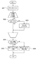
この多数決判断のロジックと多数決判断による真データの取得ロジックのフローを図6を参照して説明する。
【0029】
まず、中心周波数CF1による信号より演算された位置情報(たとえば、距離値)と中心周波数CF2による信号より演算された位置情報との差分(偏差)が予め設定されているしきい値以内であるか否かを判別する(ステップS11)。しきい値以内であれば(ステップS12肯定)、つぎに、中心周波数CF2による信号より演算された位置情報と中心周波数CF3による信号より演算された位置情報との差分(偏差)が予め設定されているしきい値以内であるか否かを判別する(ステップS12)。
【0030】
しきい値以内であれば(ステップS12肯定)、これは、電波障害が発生していない時である。この場合には、中心周波数CF1による信号より演算された位置情報と中心周波数CF2による信号より演算された位置情報と中心周波数CF3による信号より演算された位置情報の全ての真データとして平均値演算を行う(ステップS13)。
【0031】
これに対し、中心周波数CF2による信号より演算された位置情報と中心周波数CF3による信号より演算された位置情報との差分がしきい値以内でなければ(ステップS12否定)、これは、中心周波数CF3に関して電波障害が発生した時である。この場合には、中心周波数CF1による信号より演算された位置情報と中心周波数CF2による信号より演算された位置情報を真データとして平均値演算を行う(ステップS14)。
【0032】
中心周波数CF1による信号より演算された位置情報と中心周波数CF2による信号より演算された位置情報との差分がしきい値以内でなければ(ステップS11否定)、つぎに、中心周波数CF1による信号より演算された位置情報と中心周波数CF3による信号より演算された位置情報との差分(偏差)が予め設定されているしきい値以内であるか否かを判別する(ステップS15)。
【0033】
しきい値以内であれば(ステップS15肯定)、これは、中心周波数CF2に関して電波障害が発生した時である。この場合には、中心周波数CF1による信号より演算された位置情報と中心周波数CF3による信号より演算された位置情報を真データとして平均値演算を行う(ステップS16)。
【0034】
中心周波数CF1による信号より演算された位置情報と中心周波数CF3による信号より演算された位置情報との差分がしきい値以内でなければ(ステップS15否定)、つぎに、中心周波数CF2による信号より演算された位置情報と中心周波数CF3による信号より演算された位置情報との差分(偏差)が予め設定されているしきい値以内であるか否かを判別する(ステップS17)。
【0035】
しきい値以内であれば(ステップS17肯定)、これは、中心周波数CF1に関して電波障害が発生した時である。この場合には、中心周波数CF2による信号より演算された位置情報と中心周波数CF3による信号より演算された位置情報を真データとして平均値演算を行う(ステップS16)。
【0036】
中心周波数CF2による信号より演算された位置情報と中心周波数CF3による信号より演算された位置情報との差分もしきい値以内でなければ(ステップS17否定)、これは、電波障害の影響を受けていない真データを抽出できない時である。この場合には、警告出力を行い(ステップS19)、レーダ検知が不可能(計測不能)であることを、表示器(計器パネル)31で視覚表示および/またはスピーカ32による音声出力で、ドライバに知らせ、ドライバへの注意喚起を行う。電波障害時の表示器31の表示は、たとえば、図2(b)に示されているように、レーダ表示部31Aに、×印31Bを表示することにより行われる。
【0037】
他の実施形態として、受信された反射波をミキサ16でダウンコンバートした中間周波(IF)信号からスペクトラムを算出し、何らかの電波障害により、スペクトラムの一部またはそのすべてが異なる波形と判断されたときに、それを異常と判断して排除し、図6に示されている多数決判断による真データの取得ロジックフローと同様のフローで、真データの平均値を取得することができる。
【0038】
スペクトラム波形の比較ロジックのフローを図7を参照して説明する。
まず、カウンタを0リセットする(ステップS21)。つぎに、中心周波数CF1によるスペクトラムと中心周波数CF2によるスペクトラムの所定周波数域(0〜40Hz)における各周波数(たとえば、1Hz毎のサンプリング周波数)について信号強度の差分が予め設定されたしきい値以内であるか否かの判別を行う(ステップS22)。しきい値以内であれば、カウンタをインクリメントする(ステップS23)。この判別ステップS22とカウンタインクリメントステップS23は、0〜40Hzの周波数範囲で繰り返し行われる。
【0039】
判別ステップS22とカウンタインクリメントステップS23が完了すると、カウンタ値が所定値、たとえば30以上であるか、否かの判別を行う(ステップS24)。カウンタ値が30以上であれば(ステップS24肯定)、同じスペクトラム波形と判断し(ステップS25)、これに対し、カウンタ値が30未満であれば(ステップS24否定)、異なるスペクトラム波形と判断する(ステップS26)。
このスペクトラム波形の比較は、同様に、中心周波数CF1によるスペクトラムと中心周波数CF3によるペクトラム、中心周波数CF2によるスペクトラムと中心周波数CF3によるペクトラムに関しても、同様に行われる。
【0040】
次に、FMCW(Frequency Modulated Continuous Wave)方式レーダに適用した実施形態について、図7を用いて説明する。図8(a)は、FMCW方式レーダの変調パターンを示し、図8(b)は、送信電波と受信電波をミキサでダウンコンバートしたドプラ周波数を示している。
【0041】
FMCW方式レーダで、上述の2周波CW方式レーダと異なるところは、周波数変調を図8(a)に示されているように、時間とともに直線的に変化(三角変調)させるところである。
FMCW方式レーダでは、三角波の上昇区間と下降区間を1フレームとして信号処理を行い、数フレームをごとに中心周波数をCF1、CF2、CF3…とシフトさせる。
【0042】
この変調方式において、送信信号と受信信号の間には、先行車までの電波の往復距離に相当する時間遅れと、相対速度によるドップラシフトが生じ、これらの周波数差(ドップラ周波数)は、三角波の上昇区間でfb1、下降区間でfb2となる。
これらのドップラ信号に対してFFT(高速フーリエ変換)処理が施されると、図9に示されているように、周波数領域の中で、信号ピークとして、先行車等のターゲットを抽出することができる。この際、ターゲットのピークが現れる周波数Fb1、Fb2は、ターゲットとの距離に比例する。すなわち、周波数0は、距離が0であることを示す。
【0043】
ここで、CF2の送信周波数付近で、有害電波Eに電波障害を受けると、誤った周波数にピークPeが検出されたり、もしくは、正しいピークが得られないため、結果として誤った先行車の位置情報を出力してしまうことが考えられる。
そこで、少なくとも3つ以上の中心周波数から得られる信号処理の結果で多数決を行い、お互いの信号処理結果の中で相違があると判断されるときは少ない方の信号処理結果を異常と判断して排除する。この結果、2周波CW方式と同様に、誤った先行車の位置情報の出力を抑制することが可能となる。
【0044】
次に、モノパルス方式レーダに適用した実施形態を図10〜図12を参照して説明する。図10(a)は電波レーダ装置50を装着した自車輌100が先行車101に追従走行しているのを上方から見たものである。モノパルスレーダでは、図10(b)に示されているように、1つの送信アンテナTxに対して2つの受信アンテナRx1、Rx2が設けられており、受信アンテナRx1とRx2で受信する反射波の信号強度の比から先行車の方位角度を計測する。
【0045】
一般的に車載用電波レーダでは、電波の放射範囲において路面や側壁で反射するため、先行車101に対して最短の軌跡を経て受信される直接波と、路面や側壁に反射して受信される間接波が存在する。図11に示されているように、ある距離Rangeに存在する反射物Xから受信される反射波には、直接波Wdに加え、路面に反射して受信される間接波Wirがあり、直接波Wdと間接波Wiの合成において、それぞれの経路差(=位相差)に依存して信号の減衰が生じる。
【0046】
また、経路差(=位相差)は距離の変化に加え、反射物の高さや送信する電波の周波数にも依存する。図12は、ある周波数の送信波を用いた場合に、ある高さにある反射物の距離と減衰量の分布を示している。側壁に反射して受信される間接波においても、路面に反射して受信される間接波との間で減衰を生じて固有の減衰分布を持つことになる。
【0047】
ここで、図13に示されているように、電波レーダ装置50を装着した自車輌100が先行車101に追従して走行する場合では、先行車101からの直接波Wdに加え、側壁等に反射して受信される間接波Wisと路面に反射して受信される反射波が受信される。
通常、側壁からの間接波Wisは、側壁で反射による減衰があるため、直接波EWdより受信強度が強くなることはまれである。このため、モノパルスレーダで方位角度を計測するとき、概ね、直接波Wdによって正しい計測が行われる。
【0048】
しかし、距離によっては側壁からの間接波Wisより、直接波Wdの信号の方が多く減衰し、結果として、車輌101Eのように誤った方位角度が計測されてしまうことがある。そこで、この場合も、少なくとも3つの異なる中心周波数で方位角度の計測を行うことで、まれにある周波数で直接波が大きく減衰したとしても、多数決の結果、相違のある信号処理結果を異常と判断して排除することが可能となる。
【0049】
次に、他の実施形態として、2周波CWレーダ装置に応用した例を、図14を用いて説明する。このレーダ方式は既に述べたとおり、中心周波数を中心に2種類の周波数f1と周波数f2の電波を放射する変調方式である。
ここで、いずれかの送信周波数、たとえば、周波数f2で有害電波により電波障害を受けた場合、図14に示されているスペクトラムのように、周波数f1によるスペクトラムと周波数f2によるスペクトラムの一部またはすべてにおいて波形の相違が生じる。この場合、周波数f1によるスペクトラムと周波数f2によるスペクトラムとで、ターゲット情報となるピーク周波数が、P(f1)とP(f2)で異なっている。
【0050】
そこで、f1とf2のスペクトラム波形を比較し、相違があると判断されるときは異常と判断して、フェール信号を出力することができる。
この場合のスペクトラム波形の比較ロジックのフローを図15を参照して説明する。まず、カウンタを0リセットする(ステップS31)。つぎに、周波数f1によるスペクトラムと周波数f2によるスペクトラムの所定周波数域(0〜40Hz)における各周波数(たとえば、1Hz毎のサンプリング周波数)について信号強度の差分が予め設定されたしきい値以内であるか否かの判別を行う(ステップS32)。
しきい値以内であれば、カウンタをインクリメントする(ステップS33)。この判別ステップS32とカウンタインクリメントステップS33は、0〜40Hzの周波数範囲で繰り返し行われる。
【0051】
判別ステップS32とカウンタインクリメントステップS33が完了すると、カウンタ値が所定値、たとえば30以上であるか、否かの判別を行う(ステップS34)。カウンタ値が30以上であれば(ステップS24肯定)、干渉なしと判断し(ステップS35)、これに対し、カウンタ値が30未満であれば(ステップS24否定)、干渉ありと判断する(ステップS36)。
【0052】
以上、実施形態において説明したように、本発明による車載用電波レーダ装置では、自車前方へ中心周波数を一定時間毎に異なる周波数に切替えて発振させる発振手段を備え、該発振手段で送信される複数の中心周波数毎に先行車の位置情報を算出し、少なくとも3つ以上の中心周波数で算出された位置情報の中で多数決を行い、他車輌のレーダ装置から送信された電波との干渉により矛盾する位置情報が算出された場合に、この結果を多数決により異常値と判断し排除することで、干渉による障害物の誤検知を防ぐことが可能となる。
【0053】
またこの効果は、多数決判断に用いる判断基準には位置情報に限らず、受信された反射波をダウンコンバートしたIF信号のスペクトラムの波形を比較することで誤検知の判断を行うことも可能である。
また、他車のレーダ波との干渉に限らず、自車のレーダ波が最短の軌跡とは別に、路面や路側壁等より反射して複数の軌跡を経由して受信される電波に干渉した場合においても、同様の多数決判定によって誤検知を防ぐことが可能となる。さらに、2周波CW方式レーダでは、受信される2周波の受信スペクトラムを比較することで誤検知の判断を行うことが可能となる。
【0054】
複数の中心周波数において干渉が発生し、上記いずれかの方法による誤検知の対策手段を用いたにもかかわらず、異常と判断される位置情報を排除することが困難と判断されるときには、ドライバにレーダによる障害物検知が不可能であると報告する表示手段で、注意を促すことが可能となる。
【0055】
この結果、従来技術のような特別な回路や判断部を必要とせず、コストアップなしに干渉による誤検知の防止を可能とする車載用レーダ装置を実現することができる。
尚、上述の実施形態では、特に76GHz帯に関して詳述したが、他の周波数帯においても同様の効果が得られることは言うまでもない。
【0056】
【発明の効果】
以上の説明から理解される如く、この発明による車載用レーダ装置によれば、少なくとも3つ以上の中心周波数で算出された位置情報の中で多数決判断を行うから、特別な回路や判断部を必要とせず、コストアップなしに干渉を含む電波障害による誤検知を防止することができる。
【図面の簡単な説明】
【図1】本発明による車載用レーダ装置の一実施形態を示すブロック図である。
【図2】(a)は本発明による車載用レーダ装置の信号処理部の一実施形態を示すブロック図、(b)は表示器の実施形態を示す説明図である。
【図3】2周波CWレーダにおいて一定周期で中心周波数をシフトしたときの送信信号放射パターンである。
【図4】送信信号が電波障害を受けた場合の受信信号をダウンコンバートしたスペクトラム波形の一例を示す波形図である。
【図5】送信信号が電波障害を受けた場合の受信信号をダウンコンバートしたスペクトラム波形の一例を示す波形図である。
【図6】本発明の一つの実施形態における多数決判断のロジックと多数決判断による真データの取得ロジックのフローチャートである。
【図7】本発明の一つの実施形態におけるスペクトラム波形の比較ロジックのフローチャートである。
【図8】(a)はFMCWでの一定周期で中心周波数をシフトした時の送信信号パターンを示す波形図、(b)はそれのドップラ周波数特性を示す図である。
【図9】電波障害が発生したときの受信信号をダウンコンバートしたスペクトラム波形を示す波形図である。
【図10】(a)はモノパルスレーダ装置にて先行車の方位角度を計測する手段を説明する図、(b)モノパルスレーダ装置を示す図である。
【図11】障害物からの反射波が複数の経路を経て受信されるケースの電波の軌跡を示す図である。
【図12】2つの経路を経て受信される反射波の干渉により、障害物の距離に対して受信信号電力が変化することを示すグラフである。
【図13】多重反射により先行車位置を誤って検出した場合の走行パターンを示す図である。
【図14】2周波CWのf1とf2の周波数間で、電波障害により受信信号に相違が生じた場合のスペクトラム波形を示す波形図である。
【図15】2周波CWにおけるスペクトラム波形の比較ロジックのフローチャートである。
【符号の説明】
10 車載用レーダ装置
11 信号処理部
12 変調器
13 発振器
14 送信アンテナ
15 受信アンテナ
16 ミキサ
17 アナログ回路部
18 A/Dコンバータ
19 FFT部
21 位置情報算出部
22 フィルタ部
23 データ格納部
24 位置情報出力部
31 表示器
32 スピーカ
50 電波レーダ装置
100 自車輌
101 先行車[0001]
TECHNICAL FIELD OF THE INVENTION
The present invention relates to an on-vehicle radio radar device and a signal processing method thereof, and more particularly, to an on-vehicle radio radar device for detecting a relative position of a preceding vehicle with respect to a host vehicle and a signal processing method thereof.
[0002]
[Prior art]
Currently, the 76 GHz band is allocated to the application frequency of the on-vehicle radio radar used in automobiles and the like, and it is obliged to use it within the range of 1 GHz from 76 GHz to 77 GHz.
[0003]
If another radio radar (for example, an oncoming vehicle) that uses the exact same frequency as the own vehicle's radio radar is within the propagation range, interference may occur and the position of the preceding vehicle may not be accurately detected. There is.
As a countermeasure, for example, as disclosed in Japanese Patent Application Laid-Open No. Hei 4-236388, an ID signal is superimposed on a radar wave radiated from a radio wave radar device, and the received radar wave is determined as a criterion based on the ID signal. It judges whether it is another car radar wave of the same frequency, and if the received radar wave is another car radar wave of the same frequency as the own vehicle, erroneous detection is performed by changing the frequency of the own car radar wave. There are techniques to prevent this.
[0004]
[Problems to be solved by the invention]
However, in the above-described conventional technology, in addition to an ID signal oscillator for superimposing an ID signal on a radiated radar wave, an ID signal determining unit that determines whether the ID signal is of the own vehicle after demodulating a received wave is used. It becomes necessary, and as a result, leads to an increase in the cost of the radar device.
[0005]
SUMMARY OF THE INVENTION The present invention has been made to solve the above-described problems, and has as its object to eliminate the need for a special circuit or determination unit and to eliminate erroneous detection due to radio interference including interference without increasing costs. An object of the present invention is to provide a vehicle-mounted radar device and a signal processing method thereof.
[0006]
[Means for Solving the Problems]
In order to achieve the above object, an on-vehicle radar device according to the present invention emits a radio wave modulated around a certain frequency in front of the own vehicle from a transmitting antenna, and receives a reflected wave from a preceding vehicle or the like with a receiving antenna. In an on-vehicle radio radar device for detecting at least a relative position of a preceding vehicle with respect to the own vehicle, an oscillating unit that oscillates by switching a center frequency of a radio wave to be transmitted to a different frequency at regular time intervals, and transmitted by the oscillating unit. Signal processing means for calculating position information of the preceding vehicle for each of the plurality of center frequencies. The signal processing means performs a majority decision among the position information calculated at least at three or more center frequencies, and when the position information inconsistent due to some radio interference is calculated, as a result of the majority, the smaller position information is determined. Is judged as an abnormal value and eliminated.
[0007]
According to the on-vehicle radar device according to the present invention, a majority decision is made among the position information calculated with at least three or more center frequencies, and contradictory position information due to interference with a radio wave transmitted from a radar device of another vehicle is obtained. When calculated, the result is determined as an abnormal value by majority decision and is excluded, so that erroneous detection of an obstacle due to interference can be prevented.
[0008]
Further, the on-vehicle radar device according to the present invention emits a radio wave modulated around a certain frequency in front of the own vehicle from a transmitting antenna, receives a reflected wave from a preceding vehicle or the like with a receiving antenna, and at least receives the reflected wave from the preceding vehicle. In an on-vehicle radio radar apparatus for detecting a relative position with respect to a vehicle, an oscillating means for oscillating by switching a center frequency of a radio wave to be transmitted to a different frequency at predetermined time intervals, and receiving reflected waves by at least three or more center frequencies. A signal processing means for calculating a spectrum from the intermediate frequency signal down-converted by each mixer, and when a part or all of the spectrum is determined to have a different waveform due to some radio interference, it is determined that the waveform is abnormal and eliminated. ing.
[0009]
ADVANTAGE OF THE INVENTION According to the vehicle-mounted radar apparatus by this invention, it can judge erroneous detection by comparing the waveform of the spectrum of the IF signal which down-converted the received reflected wave.
[0010]
The on-vehicle radar device according to the present invention alternately radiates two different frequencies forward of the own vehicle, receives a reflected wave from the preceding vehicle by a receiving antenna, and stores the relative distance information of the preceding vehicle in the two frequencies. The present invention can be applied to both a two-frequency CW radar system that calculates from a phase difference and an FMCW radar system that performs frequency modulation that changes in a predetermined pattern with time.
[0011]
Further, the on-vehicle radar device according to the present invention emits two different frequencies alternately forward of the own vehicle, receives a reflected wave from the preceding vehicle with a receiving antenna, and outputs relative distance information of the preceding vehicle to the two frequencies. In a two-frequency CW radar type in-vehicle radio wave radar device calculated from the phase difference of the above, the reception spectrum of the two frequencies received by the radar device is calculated, and a part or all of the spectrum has a different waveform due to some radio interference. When it is determined that there is an abnormality, a signal processing means for determining the abnormality is provided.
[0012]
According to the on-vehicle radar device according to the present invention, the erroneous detection can be determined by comparing the received spectrums of the two received frequencies.
[0013]
Further, the on-vehicle radar device according to the present invention includes means for reporting to the driver that obstacle detection by the radar is impossible when interference occurs at a plurality of center frequencies and all are determined to be abnormal. ing. A display that performs a visual display and / or a speaker that performs an audio output can be used to alert the driver.
[0014]
In order to achieve the above-mentioned object, a signal processing method for an on-vehicle radio radar device according to the present invention radiates a radio wave modulated around a certain frequency in front of the own vehicle from a transmitting antenna and reflects the radio wave from a preceding vehicle or the like. In a signal processing method of an on-vehicle radio radar device that receives a wave with a receiving antenna and detects at least a relative position of a preceding vehicle with respect to the own vehicle, a center frequency of a radio wave to be transmitted is switched to a different frequency at predetermined time intervals to oscillate. Calculates the position information of the preceding vehicle for each of a plurality of transmitted center frequencies, performs a majority decision among the position information calculated at least at three or more center frequencies, and calculates contradictory position information due to some kind of radio interference. In this case, as a result of the majority decision, the smaller position information is determined to be an abnormal value and is excluded.
[0015]
Further, the signal processing method of the on-vehicle radio radar device according to the present invention radiates a radio wave modulated around a certain frequency in front of the own vehicle from a transmitting antenna, receives a reflected wave from a preceding vehicle or the like by a receiving antenna, In a signal processing method of an on-vehicle radio radar device for detecting at least a relative position of a preceding vehicle with respect to the own vehicle, a center frequency of a radio wave to be transmitted is switched to a different frequency at regular time intervals to oscillate, and a received reflected wave is mixed by a mixer. A spectrum is calculated from the down-converted intermediate frequency signal, and when a part or all of the spectrum is determined to have a different waveform due to some radio interference, it is determined to be abnormal and eliminated.
[0016]
Also, the signal processing method of the on-vehicle radio radar device according to the present invention is characterized in that two different frequencies are alternately radiated forward of the own vehicle, a reflected wave from the preceding vehicle is received by the receiving antenna, and the relative distance of the preceding vehicle is determined. In a signal processing method for an on-vehicle radio wave radar device of a two-frequency CW radar system for calculating information from a phase difference between two frequencies, a reception spectrum of two frequencies received by the radar device is calculated, and the spectrum is received due to some radio interference. Is determined to be abnormal when it is determined that some or all of them have different waveforms.
[0017]
BEST MODE FOR CARRYING OUT THE INVENTION
Hereinafter, embodiments of a vehicle-mounted radar device according to the present invention will be described with reference to the drawings. FIG. 1 shows an embodiment of an on-vehicle radio wave radar device according to the present invention. The in-vehicle radio radar device includes a
[0018]
The
[0019]
A radio signal that is reflected and returned from a target such as a vehicle or an obstacle is received by a receiving
[0020]
The beat signal sent to the
[0021]
The
[0022]
The position
[0023]
FIG. 3 shows an example of a transmission signal in the on-vehicle radio radar device according to the present invention. The transmission signal emits a radio wave modulated to two kinds of frequencies f1 and f2 around a center frequency, and measures a distance from a phase difference between the two kinds of radio waves reflected and received by an obstacle to measure a distance. In a Wave (Wave) radar, the center frequency CF (f1, f2) is shifted at a constant period.
The shift of the center frequency and the modulation of the two frequencies are performed by controlling the
[0024]
FIG. 4 shows a spectrum waveform obtained by subjecting a beat signal obtained from the
[0025]
An equation for calculating the relative speed Rate of the preceding vehicle from the Doppler frequency fd1 is expressed as follows.
Rate = C (fd1 / 2f1)
Where C: speed of light
[0026]
By calculating the phase difference φ with respect to each peak of the transmission waves f1 and f2, the relative distance Range of the preceding vehicle is calculated as follows.
Range = C · φ / 4π · Δf
Δf = f1-f2
The above method of calculating the position information of the preceding vehicle does not depend on the switching of the center frequency (CF1, CF2, CF3...) Unless the frequency width of f1 and f2 is changed.
[0027]
Here, as shown in FIG. 3, when a harmful radio wave E causes radio interference at the transmission frequency f1 of CF2, it is detected as an erroneous peak (target information) B as in the spectrum shown in FIG. It is also conceivable that the noise rises as shown in the spectrum shown in FIG. 5 and that incorrect position information of the preceding vehicle is output as a result.
[0028]
Therefore, a majority decision is made using the signal processing results obtained from at least three or more center frequencies (CF1, CF2, CF3...), And when it is determined that there is a difference between the respective signal processing results, the smaller one is used. The signal processing result is determined to be abnormal and eliminated. As a result, it is possible to suppress output of erroneous position information of the preceding vehicle.
The flow of the logic of the majority decision and the logic of acquiring the true data based on the majority decision will be described with reference to FIG.
[0029]
First, is a difference (deviation) between position information (for example, a distance value) calculated from a signal based on the center frequency CF1 and position information calculated from a signal based on the center frequency CF2 within a preset threshold value? It is determined whether or not it is (step S11). If it is within the threshold value (Yes at step S12), then a difference (deviation) between the position information calculated from the signal at the center frequency CF2 and the position information calculated from the signal at the center frequency CF3 is set in advance. It is determined whether or not it is within the threshold (step S12).
[0030]
If it is within the threshold value (Yes at Step S12), this is when no radio interference has occurred. In this case, the average value calculation is performed as all true data of the position information calculated from the signal based on the center frequency CF1, the position information calculated based on the signal based on the center frequency CF2, and the position information calculated based on the signal based on the center frequency CF3. Perform (Step S13).
[0031]
On the other hand, if the difference between the position information calculated from the signal based on the center frequency CF2 and the position information calculated based on the signal based on the center frequency CF3 is not within the threshold value (No at Step S12), the difference between the center information and the center frequency CF3 Is when radio interference occurs. In this case, the average value is calculated using the position information calculated from the signal based on the center frequency CF1 and the position information calculated based on the signal based on the center frequency CF2 as true data (step S14).
[0032]
If the difference between the position information calculated from the signal based on the center frequency CF1 and the position information calculated based on the signal based on the center frequency CF2 is not within the threshold (No at Step S11), the calculation is performed based on the signal based on the center frequency CF1. It is determined whether or not the difference (deviation) between the obtained position information and the position information calculated from the signal based on the center frequency CF3 is within a preset threshold value (step S15).
[0033]
If it is within the threshold value (Yes at Step S15), this is the time when a radio interference has occurred with respect to the center frequency CF2. In this case, the average value is calculated using the position information calculated from the signal based on the center frequency CF1 and the position information calculated based on the signal based on the center frequency CF3 as true data (step S16).
[0034]
If the difference between the position information calculated from the signal based on the center frequency CF1 and the position information calculated based on the signal based on the center frequency CF3 is not within the threshold (No at Step S15), the calculation is performed based on the signal based on the center frequency CF2. It is determined whether or not the difference (deviation) between the obtained position information and the position information calculated from the signal based on the center frequency CF3 is within a preset threshold value (step S17).
[0035]
If it is within the threshold value (Yes at Step S17), this is the time when a radio wave disturbance occurs with respect to the center frequency CF1. In this case, an average value calculation is performed using the position information calculated from the signal based on the center frequency CF2 and the position information calculated based on the signal based on the center frequency CF3 as true data (step S16).
[0036]
If the difference between the position information calculated from the signal based on the center frequency CF2 and the position information calculated based on the signal based on the center frequency CF3 is also within the threshold (No at Step S17), the difference is not affected by the radio wave interference. This is when the true data cannot be extracted. In this case, a warning is output (step S19), and the fact that radar detection is impossible (measurement is impossible) is notified to the driver by visual display on the display (instrument panel) 31 and / or audio output from the
[0037]
As another embodiment, a spectrum is calculated from an intermediate frequency (IF) signal obtained by down-converting a received reflected wave by a
[0038]
The flow of the spectrum waveform comparison logic will be described with reference to FIG.
First, the counter is reset to 0 (step S21). Next, the difference between the signal intensities for each frequency (for example, sampling frequency every 1 Hz) in a predetermined frequency range (0 to 40 Hz) of the spectrum based on the center frequency CF1 and the spectrum based on the center frequency CF2 is within a preset threshold value. It is determined whether or not there is (step S22). If not, the counter is incremented (step S23). The determination step S22 and the counter increment step S23 are repeatedly performed in a frequency range of 0 to 40 Hz.
[0039]
When the determination step S22 and the counter increment step S23 are completed, it is determined whether or not the counter value is a predetermined value, for example, 30 or more (step S24). If the counter value is 30 or more (Yes at Step S24), it is determined that the spectrum waveform is the same (Step S25). If the counter value is less than 30 (No at Step S24), it is determined that the spectrum waveform is different (Step S24). Step S26).
The comparison of the spectrum waveforms is similarly performed for the spectrum at the center frequency CF1 and the spectrum at the center frequency CF3, and the spectrum at the center frequency CF2 and the spectrum at the center frequency CF3.
[0040]
Next, an embodiment applied to an FMCW (Frequency Modulated Continuous Wave) radar will be described with reference to FIG. FIG. 8A shows a modulation pattern of the FMCW radar, and FIG. 8B shows Doppler frequencies obtained by down-converting a transmission radio wave and a reception radio wave by a mixer.
[0041]
The FMCW radar differs from the above-described two-frequency CW radar in that the frequency modulation is changed linearly (triangular modulation) with time as shown in FIG. 8A.
In the FMCW radar, signal processing is performed with the rising section and the falling section of the triangular wave as one frame, and the center frequency is shifted to CF1, CF2, CF3... Every several frames.
[0042]
In this modulation method, a time delay corresponding to a reciprocating distance of a radio wave to a preceding vehicle and a Doppler shift due to a relative speed occur between a transmission signal and a reception signal, and a frequency difference (Doppler frequency) between the transmission signal and the reception signal is a triangular wave. Fb1 in the ascending section and fb2 in the descending section.
When FFT (Fast Fourier Transform) processing is performed on these Doppler signals, a target such as a preceding vehicle can be extracted as a signal peak in the frequency domain, as shown in FIG. it can. At this time, the frequencies Fb1 and Fb2 where the peak of the target appears are proportional to the distance from the target. That is, a frequency of 0 indicates that the distance is 0.
[0043]
Here, if a harmful radio wave E causes a radio interference near the transmission frequency of CF2, a peak Pe is detected at an erroneous frequency, or a correct peak cannot be obtained. May be output.
Therefore, a majority decision is made based on the signal processing results obtained from at least three or more center frequencies, and when it is determined that there is a difference among the signal processing results, the smaller signal processing result is determined to be abnormal. Exclude. As a result, similarly to the two-frequency CW method, it is possible to suppress output of erroneous position information of the preceding vehicle.
[0044]
Next, an embodiment applied to a monopulse radar will be described with reference to FIGS. FIG. 10A is a top view of the
[0045]
In general, in an on-vehicle radio radar, since a radio wave is reflected on a road surface or a side wall in a radiation range of a radio wave, a direct wave received through a shortest trajectory with respect to the preceding
[0046]
The path difference (= phase difference) depends on the height of the reflector and the frequency of the radio wave to be transmitted, in addition to the change in the distance. FIG. 12 shows the distribution of the distance and attenuation of a reflector at a certain height when a transmission wave of a certain frequency is used. Even an indirect wave reflected and received on the side wall has an inherent attenuation distribution by attenuating between the indirect wave reflected and received on the road surface.
[0047]
Here, as shown in FIG. 13, when the
Normally, the indirect wave Wis from the side wall is attenuated by reflection at the side wall, so that the reception intensity is rarely higher than that of the direct wave EWd. Therefore, when the azimuth angle is measured by the monopulse radar, the correct measurement is generally performed by the direct wave Wd.
[0048]
However, depending on the distance, the signal of the direct wave Wd is attenuated more than the indirect wave Wis from the side wall, and as a result, the wrong azimuth angle may be measured as in the case of the vehicle 101E. Therefore, in this case as well, by measuring the azimuth at at least three different center frequencies, even if the direct wave is greatly attenuated at a rare frequency, it is determined that the signal processing result having a difference as a result of the majority decision is abnormal. Can be eliminated.
[0049]
Next, as another embodiment, an example in which the present invention is applied to a two-frequency CW radar device will be described with reference to FIG. As described above, this radar system is a modulation system that radiates radio waves of two types of frequencies f1 and f2 around a center frequency.
Here, when an harmful radio wave interferes with any of the transmission frequencies, for example, the frequency f2, a part of or all of the spectrum at the frequency f1 and the spectrum at the frequency f2 as shown in the spectrum shown in FIG. , A difference in waveform occurs. In this case, the peak frequency serving as the target information differs between P (f1) and P (f2) in the spectrum at the frequency f1 and the spectrum at the frequency f2.
[0050]
Then, the spectrum waveforms of f1 and f2 are compared, and when it is determined that there is a difference, it is determined that there is an abnormality, and a fail signal can be output.
The flow of the spectrum waveform comparison logic in this case will be described with reference to FIG. First, the counter is reset to 0 (step S31). Next, is the signal strength difference between each frequency (for example, sampling frequency every 1 Hz) in a predetermined frequency range (0 to 40 Hz) of the spectrum based on the frequency f1 and the spectrum based on the frequency f2 within a predetermined threshold value? It is determined whether or not it is (step S32).
If it is within the threshold, the counter is incremented (step S33). The determination step S32 and the counter increment step S33 are repeatedly performed in a frequency range of 0 to 40 Hz.
[0051]
When the determination step S32 and the counter increment step S33 are completed, it is determined whether or not the counter value is a predetermined value, for example, 30 or more (step S34). If the counter value is 30 or more (Yes at Step S24), it is determined that there is no interference (Step S35), whereas if the counter value is less than 30 (No at Step S24), it is determined that there is interference (Step S36). ).
[0052]
As described above in the embodiment, the in-vehicle radio radar device according to the present invention includes the oscillating means for oscillating by switching the center frequency to a different frequency at predetermined time intervals in front of the own vehicle, and transmitting by the oscillating means. The position information of the preceding vehicle is calculated for each of a plurality of center frequencies, a majority decision is made among the position information calculated at least at three or more center frequencies, and contradiction occurs due to interference with radio waves transmitted from radar devices of other vehicles. When the position information to be calculated is calculated, the result is determined to be an abnormal value by majority decision and is excluded, whereby erroneous detection of an obstacle due to interference can be prevented.
[0053]
Further, this effect is not limited to the position information as a criterion used for the majority decision, and it is also possible to judge erroneous detection by comparing a spectrum waveform of an IF signal obtained by down-converting a received reflected wave. .
In addition to the interference with the radar wave of another vehicle, the radar wave of the own vehicle interferes with the electric wave received via a plurality of trajectories reflected from a road surface or a road side wall separately from the shortest trajectory. In this case, it is possible to prevent erroneous detection by the same majority decision. Furthermore, in the two-frequency CW radar, it is possible to determine erroneous detection by comparing the received spectrums of the two received frequencies.
[0054]
When interference occurs at a plurality of center frequencies, and it is determined that it is difficult to eliminate the position information determined to be abnormal despite using the countermeasure for erroneous detection by any of the above methods, It is possible to call attention by a display unit that reports that obstacle detection by the radar is impossible.
[0055]
As a result, it is possible to realize a vehicle-mounted radar device that does not require a special circuit or determination unit unlike the related art, and that can prevent erroneous detection due to interference without increasing costs.
Although the above embodiment has been described in detail with respect to the 76 GHz band in particular, it goes without saying that similar effects can be obtained in other frequency bands.
[0056]
【The invention's effect】
As can be understood from the above description, according to the on-vehicle radar device of the present invention, since a majority decision is made among the position information calculated with at least three or more center frequencies, a special circuit and a judgment unit are required. It is possible to prevent erroneous detection due to radio interference including interference without increasing the cost.
[Brief description of the drawings]
FIG. 1 is a block diagram showing an embodiment of a vehicle-mounted radar device according to the present invention.
FIG. 2A is a block diagram illustrating an embodiment of a signal processing unit of a vehicle-mounted radar device according to the present invention, and FIG. 2B is an explanatory diagram illustrating an embodiment of a display device.
FIG. 3 is a transmission signal radiation pattern when a center frequency is shifted at a constant period in a two-frequency CW radar.
FIG. 4 is a waveform diagram showing an example of a spectrum waveform obtained by down-converting a reception signal when a transmission signal is subject to radio interference.
FIG. 5 is a waveform diagram showing an example of a spectrum waveform obtained by down-converting a reception signal when a transmission signal is subject to radio wave interference.
FIG. 6 is a flowchart of logic for majority decision and logic for acquiring true data based on majority decision in one embodiment of the present invention.
FIG. 7 is a flow chart of a spectrum waveform comparison logic in one embodiment of the present invention.
FIG. 8A is a waveform diagram showing a transmission signal pattern when a center frequency is shifted at a constant period in the FMCW, and FIG. 8B is a diagram showing Doppler frequency characteristics thereof.
FIG. 9 is a waveform diagram showing a spectrum waveform obtained by down-converting a received signal when a radio wave obstruction occurs.
10A is a diagram illustrating a means for measuring an azimuth angle of a preceding vehicle by a monopulse radar device, and FIG. 10B is a diagram illustrating a monopulse radar device.
FIG. 11 is a diagram illustrating a locus of a radio wave in a case where a reflected wave from an obstacle is received through a plurality of paths.
FIG. 12 is a graph showing that received signal power changes with distance to an obstacle due to interference of reflected waves received via two paths.
FIG. 13 is a diagram showing a traveling pattern when a preceding vehicle position is erroneously detected by multiple reflection.
FIG. 14 is a waveform diagram showing a spectrum waveform when a difference occurs in a received signal due to a radio wave interference between frequencies f1 and f2 of the two-frequency CW.
FIG. 15 is a flowchart of logic for comparing spectrum waveforms in a two-frequency CW.
[Explanation of symbols]
10 In-vehicle radar device
11 signal processing unit
12 Modulator
13 Oscillator
14 transmitting antenna
15 receiving antenna
16 mixer
17 Analog circuit section
18 A / D converter
19 FFT section
21 Position information calculation unit
22 Filter section
23 Data storage
24 Position information output unit
31 Display
32 speakers
50 Radio wave radar equipment
100 own vehicle
101 preceding car
Claims (11)
送信する電波の中心周波数を一定時間毎に異なる周波数に切替えて発振する発振手段と、
前記発振手段で送信される複数の中心周波数毎に、先行車の位置情報を算出する信号処理手段と、
を備えていることを特徴とする車載用電波レーダ装置。An in-vehicle radio radar that emits a radio wave modulated around a certain frequency in front of the own vehicle from a transmitting antenna, receives a reflected wave from a preceding vehicle by a receiving antenna, and detects at least a relative position of the preceding vehicle to the own vehicle. In the device,
Oscillating means for oscillating by switching the center frequency of the radio wave to be transmitted to a different frequency at regular intervals,
For each of a plurality of center frequencies transmitted by the oscillation means, a signal processing means for calculating position information of the preceding vehicle,
An on-vehicle radio radar device comprising:
送信する電波の中心周波数を一定時間毎に異なる周波数に切替えて発振する発振手段と、
受信された少なくとも3つ以上の中心周波数による反射波を各々ミキサでダウンコンバートした中間周波信号からスペクトラムを算出し、何らかの電波障害により該スペクトラムの一部またはそのすべてが異なる波形と判断されたときに、それを異常と判断し排除する信号処理手段と、
を備えていることを特徴とする車載用電波レーダ装置。An in-vehicle radio radar that emits a radio wave modulated around a certain frequency in front of the own vehicle from a transmitting antenna, receives a reflected wave from a preceding vehicle by a receiving antenna, and detects at least a relative position of the preceding vehicle to the own vehicle. In the device,
Oscillating means for oscillating by switching the center frequency of the radio wave to be transmitted to a different frequency at regular intervals,
A spectrum is calculated from an intermediate frequency signal obtained by down-converting the reflected waves of at least three or more received center frequencies by a mixer, and when a part or all of the spectrum is determined to have a different waveform due to some radio interference. , Signal processing means for judging it as abnormal and eliminating it,
An on-vehicle radio radar device comprising:
該レーダ装置で受信される2周波の受信スペクトラムを算出し、何らかの電波障害により該スペクトラムの一部またはそのすべてが異なる波形と判断されたときに、それを異常と判断する信号処理手段を備えていることを特徴とする車載用電波レーダ装置。A two-frequency CW radar system in which two different frequencies are alternately emitted in front of the own vehicle, a reflected wave from the preceding vehicle is received by a receiving antenna, and relative distance information of the preceding vehicle is calculated from a phase difference between the two frequencies. In the in-vehicle radio radar device,
Signal processing means for calculating a reception spectrum of the two frequencies received by the radar device, and when it is determined that a part or all of the spectrum has a different waveform due to some kind of radio interference, determines that the waveform is abnormal. An in-vehicle radio radar device characterized by:
送信する電波の中心周波数を一定時間毎に異なる周波数に切替えて発振し、送信される複数の中心周波数毎に、先行車の位置情報を算出し、少なくとも3つ以上の中心周波数で算出された位置情報の中で多数決を行い、何らかの電波障害により矛盾する位置情報が算出された場合に、多数決の結果、少ない方の位置情報を異常値と判断し排除することを特徴とする車載用電波レーダ装置の信号処理方法。An in-vehicle radio radar that emits a radio wave modulated around a certain frequency in front of the own vehicle from a transmitting antenna, receives a reflected wave from a preceding vehicle by a receiving antenna, and detects at least a relative position of the preceding vehicle to the own vehicle. In the signal processing method of the device,
The center frequency of the radio wave to be transmitted is oscillated by switching to a different frequency every predetermined time, and the position information of the preceding vehicle is calculated for each of a plurality of center frequencies to be transmitted, and the position calculated by at least three or more center frequencies In-vehicle radio radar apparatus characterized in that a majority decision is made in the information, and when contradictory position information is calculated due to some kind of radio interference, as a result of the majority decision, the smaller position information is judged to be an abnormal value and eliminated. Signal processing method.
送信する電波の中心周波数を一定時間毎に異なる周波数に切替えて発振し、受信された反射波をミキサでダウンコンバートした中間周波信号からスペクトラムを算出し、何らかの電波障害により該スペクトラムの一部またはそのすべてが異なる波形と判断されたときに、それを異常と判断し排除することを特徴とする車載用電波レーダ装置の信号処理方法。An in-vehicle radio radar that emits a radio wave modulated around a certain frequency in front of the own vehicle from a transmitting antenna, receives a reflected wave from a preceding vehicle by a receiving antenna, and detects at least a relative position of the preceding vehicle to the own vehicle. In the signal processing method of the device,
The center frequency of the radio wave to be transmitted is switched to a different frequency at fixed time intervals to oscillate, the received reflected wave is down-converted by a mixer to calculate a spectrum from the intermediate frequency signal, and a part of the spectrum or a part thereof due to some radio interference. A signal processing method for an in-vehicle radio radar device, wherein when all waveforms are determined to be different, the waveforms are determined to be abnormal and are eliminated.
該レーダ装置で受信される2周波の受信スペクトラムを算出し、何らかの電波障害により該スペクトラムの一部またはそのすべてが異なる波形と判断されたときに、それを異常と判断することを特徴とする車載用電波レーダ装置の信号処理方法。A two-frequency CW radar system in which two different frequencies are alternately emitted in front of the own vehicle, a reflected wave from the preceding vehicle is received by a receiving antenna, and relative distance information of the preceding vehicle is calculated from a phase difference between the two frequencies. In the signal processing method of the in-vehicle radio wave radar device,
Calculating a reception spectrum of two frequencies received by the radar device, and determining that a part or all of the spectrum has a different waveform due to some kind of radio interference, it is determined that the waveform is abnormal. Signal processing method for a radio wave radar device.
Priority Applications (3)
| Application Number | Priority Date | Filing Date | Title |
|---|---|---|---|
| JP2002275090A JP3688255B2 (en) | 2002-09-20 | 2002-09-20 | In-vehicle radio radar apparatus and signal processing method thereof |
| EP03021108A EP1400816A3 (en) | 2002-09-20 | 2003-09-19 | Automotive radio wave radar and signal processing |
| US10/665,562 US6972710B2 (en) | 2002-09-20 | 2003-09-22 | Automotive radio wave radar and signal processing |
Applications Claiming Priority (1)
| Application Number | Priority Date | Filing Date | Title |
|---|---|---|---|
| JP2002275090A JP3688255B2 (en) | 2002-09-20 | 2002-09-20 | In-vehicle radio radar apparatus and signal processing method thereof |
Publications (2)
| Publication Number | Publication Date |
|---|---|
| JP2004109046A true JP2004109046A (en) | 2004-04-08 |
| JP3688255B2 JP3688255B2 (en) | 2005-08-24 |
Family
ID=31944602
Family Applications (1)
| Application Number | Title | Priority Date | Filing Date |
|---|---|---|---|
| JP2002275090A Expired - Fee Related JP3688255B2 (en) | 2002-09-20 | 2002-09-20 | In-vehicle radio radar apparatus and signal processing method thereof |
Country Status (3)
| Country | Link |
|---|---|
| US (1) | US6972710B2 (en) |
| EP (1) | EP1400816A3 (en) |
| JP (1) | JP3688255B2 (en) |
Cited By (9)
| Publication number | Priority date | Publication date | Assignee | Title |
|---|---|---|---|---|
| JP2005091026A (en) * | 2003-09-12 | 2005-04-07 | Omron Corp | Two-frequency doppler range finder and detection system equipped with the same finder |
| WO2006013615A1 (en) * | 2004-08-02 | 2006-02-09 | Mitsubishi Denki Kabushiki Kaisha | Radar apparatus |
| JP2006246220A (en) * | 2005-03-04 | 2006-09-14 | Toyota Motor Corp | Communication apparatus and method for mobile object |
| JP2007033156A (en) * | 2005-07-25 | 2007-02-08 | Secom Co Ltd | Radar device |
| WO2007043475A1 (en) * | 2005-10-07 | 2007-04-19 | Kabushiki Kaisha Toshiba | Radar device and inter-rader site adjustment method |
| JP2011196757A (en) * | 2010-03-18 | 2011-10-06 | Fujitsu Ltd | Radar device and frequency control program |
| WO2015182594A1 (en) * | 2014-05-26 | 2015-12-03 | 株式会社デンソー | Vehicle-mounted radar device |
| WO2017175604A1 (en) * | 2016-04-06 | 2017-10-12 | Ntn株式会社 | Monitoring device |
| JP6797339B1 (en) * | 2020-03-13 | 2020-12-09 | 三菱電機株式会社 | Radar device |
Families Citing this family (18)
| Publication number | Priority date | Publication date | Assignee | Title |
|---|---|---|---|---|
| JP3688255B2 (en) * | 2002-09-20 | 2005-08-24 | 株式会社日立製作所 | In-vehicle radio radar apparatus and signal processing method thereof |
| JP2004226158A (en) * | 2003-01-21 | 2004-08-12 | Fujitsu Ten Ltd | Fm-cw radar device |
| JP2005156337A (en) * | 2003-11-26 | 2005-06-16 | Hitachi Ltd | On-vehicle radar device |
| US20060256854A1 (en) * | 2005-05-16 | 2006-11-16 | Hong Jiang | Parallel execution of media encoding using multi-threaded single instruction multiple data processing |
| US20070182623A1 (en) * | 2006-02-03 | 2007-08-09 | Shuqing Zeng | Method and apparatus for on-vehicle calibration and orientation of object-tracking systems |
| US7991550B2 (en) * | 2006-02-03 | 2011-08-02 | GM Global Technology Operations LLC | Method and apparatus for on-vehicle calibration and orientation of object-tracking systems |
| WO2008094172A2 (en) * | 2006-06-01 | 2008-08-07 | University Of Florida Research Foundation, Inc. | Radar microsensor for detection, tracking, and classification |
| US8432309B2 (en) * | 2010-11-29 | 2013-04-30 | Freescale Semiconductor, Inc. | Automotive radar system and method for using same |
| CN103703387B (en) * | 2011-04-19 | 2015-10-07 | 马自达汽车株式会社 | Obstacle detector for vehicle |
| EP2699937A4 (en) * | 2011-04-20 | 2015-02-25 | Freescale Semiconductor Inc | Receiver device, multi-frequency radar system and vehicle |
| US9080866B1 (en) * | 2013-06-26 | 2015-07-14 | Google Inc. | Methods and systems for detection of reflective markers at long range |
| CN104777481A (en) * | 2015-03-23 | 2015-07-15 | 王方圆 | Car collision-proof radar system |
| CN104793208A (en) * | 2015-03-25 | 2015-07-22 | 王方圆 | Automotive anti-collision radar detection method with anti-interference and multi-target recognizing performance |
| CN104765036A (en) * | 2015-03-25 | 2015-07-08 | 王方圆 | Reverse radar |
| KR101887137B1 (en) * | 2016-09-01 | 2018-09-10 | 현대자동차주식회사 | Motion detecting apparatus, motion detecting method and motion detecting antenna |
| US11348380B2 (en) * | 2018-06-08 | 2022-05-31 | Metawave Corporation | Beacon system in an autonomous vehicle radar for vehicle identification |
| CN110045358B (en) * | 2019-03-22 | 2022-06-21 | 深圳迈睿智能科技有限公司 | Microwave detector based on Doppler effect principle and anti-radiation interference method |
| WO2021108814A2 (en) * | 2021-02-18 | 2021-06-03 | Futurewei Technologies, Inc. | End-to-end self-controlled security in autonomous vehicles |
Family Cites Families (20)
| Publication number | Priority date | Publication date | Assignee | Title |
|---|---|---|---|---|
| US3383686A (en) * | 1967-01-30 | 1968-05-14 | Navy Usa | Diverse frequency echo detection system with doppler frequency coherence |
| FR2171961B1 (en) * | 1972-02-17 | 1979-04-27 | Labo Cent Telecommunicat | |
| US4400700A (en) * | 1981-06-08 | 1983-08-23 | The United States Of America As Represented By The Secretary Of The Army | Doppler frequency analysis of radar signals |
| US5017921A (en) * | 1989-12-13 | 1991-05-21 | Grumman Aerospace Corporation | Radar system and a method for operating a radar system |
| JP2932210B2 (en) | 1991-01-18 | 1999-08-09 | マツダ株式会社 | Automotive radar system |
| US5280288A (en) * | 1992-08-14 | 1994-01-18 | Vorad Safety Systems, Inc. | Interference avoidance system for vehicular radar system |
| JP2868978B2 (en) | 1993-07-30 | 1999-03-10 | 防衛庁技術研究本部長 | Shortwave radar equipment |
| JP3627389B2 (en) * | 1995-09-28 | 2005-03-09 | 株式会社デンソー | Radar equipment |
| US5828333A (en) * | 1997-01-21 | 1998-10-27 | Northrop Grumman Corporation | Multiple access diplex doppler radar |
| JP3746235B2 (en) | 2000-01-28 | 2006-02-15 | 株式会社日立製作所 | Distance measuring device |
| EP1873551B1 (en) * | 2000-08-16 | 2019-03-06 | Valeo Radar Systems, Inc. | Automotive radar systems and techniques |
| US6577269B2 (en) * | 2000-08-16 | 2003-06-10 | Raytheon Company | Radar detection method and apparatus |
| JP4111667B2 (en) * | 2000-09-26 | 2008-07-02 | 富士通テン株式会社 | FM-CW radar equipment |
| DE10108584A1 (en) * | 2001-02-22 | 2002-09-05 | Bosch Gmbh Robert | Method for interference suppression of a radar device and radar device |
| JP2002372580A (en) * | 2001-06-13 | 2002-12-26 | Mitsubishi Electric Corp | Fm-cw radar device |
| US6859705B2 (en) * | 2001-09-21 | 2005-02-22 | Ford Global Technologies, Llc | Method for operating a pre-crash sensing system with object classifier in a vehicle having a countermeasure system |
| JP3938686B2 (en) * | 2001-12-13 | 2007-06-27 | 富士通株式会社 | Radar apparatus, signal processing method and program |
| US6587072B1 (en) * | 2002-03-22 | 2003-07-01 | M/A-Com, Inc. | Pulse radar detection system |
| US6873251B2 (en) * | 2002-07-16 | 2005-03-29 | Delphi Technologies, Inc. | Tracking system and method employing multiple overlapping sensors |
| JP3688255B2 (en) * | 2002-09-20 | 2005-08-24 | 株式会社日立製作所 | In-vehicle radio radar apparatus and signal processing method thereof |
-
2002
- 2002-09-20 JP JP2002275090A patent/JP3688255B2/en not_active Expired - Fee Related
-
2003
- 2003-09-19 EP EP03021108A patent/EP1400816A3/en not_active Withdrawn
- 2003-09-22 US US10/665,562 patent/US6972710B2/en not_active Expired - Fee Related
Cited By (19)
| Publication number | Priority date | Publication date | Assignee | Title |
|---|---|---|---|---|
| JP2005091026A (en) * | 2003-09-12 | 2005-04-07 | Omron Corp | Two-frequency doppler range finder and detection system equipped with the same finder |
| US7768445B2 (en) | 2004-08-02 | 2010-08-03 | Mitsubishi Electric Corporation | Frequency-modulated radar system with variable pulse interval capability |
| WO2006013615A1 (en) * | 2004-08-02 | 2006-02-09 | Mitsubishi Denki Kabushiki Kaisha | Radar apparatus |
| JPWO2006013615A1 (en) * | 2004-08-02 | 2008-05-01 | 三菱電機株式会社 | Radar equipment |
| JP2006246220A (en) * | 2005-03-04 | 2006-09-14 | Toyota Motor Corp | Communication apparatus and method for mobile object |
| JP4631476B2 (en) * | 2005-03-04 | 2011-02-16 | トヨタ自動車株式会社 | Mobile communication device and mobile communication method |
| JP2007033156A (en) * | 2005-07-25 | 2007-02-08 | Secom Co Ltd | Radar device |
| US7864098B2 (en) | 2005-10-07 | 2011-01-04 | Kabushiki Kaisha Toshiba | Radar device and method for adjusting among radar sites |
| JPWO2007043475A1 (en) * | 2005-10-07 | 2009-04-16 | 株式会社東芝 | Adjustment method between radar device and radar site |
| WO2007043475A1 (en) * | 2005-10-07 | 2007-04-19 | Kabushiki Kaisha Toshiba | Radar device and inter-rader site adjustment method |
| JP5221142B2 (en) * | 2005-10-07 | 2013-06-26 | 株式会社東芝 | Adjustment method between radar device and radar site |
| JP2011196757A (en) * | 2010-03-18 | 2011-10-06 | Fujitsu Ltd | Radar device and frequency control program |
| WO2015182594A1 (en) * | 2014-05-26 | 2015-12-03 | 株式会社デンソー | Vehicle-mounted radar device |
| US20170153315A1 (en) * | 2014-05-26 | 2017-06-01 | Denso Corporation | In-vehicle radar apparatus |
| CN111257862A (en) * | 2014-05-26 | 2020-06-09 | 株式会社电装 | Vehicle-mounted radar device |
| US10746848B2 (en) * | 2014-05-26 | 2020-08-18 | Denso Corporation | In-vehicle radar apparatus |
| CN111257862B (en) * | 2014-05-26 | 2023-09-05 | 株式会社电装 | Vehicle-mounted radar device |
| WO2017175604A1 (en) * | 2016-04-06 | 2017-10-12 | Ntn株式会社 | Monitoring device |
| JP6797339B1 (en) * | 2020-03-13 | 2020-12-09 | 三菱電機株式会社 | Radar device |
Also Published As
| Publication number | Publication date |
|---|---|
| EP1400816A3 (en) | 2004-07-28 |
| EP1400816A2 (en) | 2004-03-24 |
| JP3688255B2 (en) | 2005-08-24 |
| US6972710B2 (en) | 2005-12-06 |
| US20040056793A1 (en) | 2004-03-25 |
Similar Documents
| Publication | Publication Date | Title |
|---|---|---|
| JP3688255B2 (en) | In-vehicle radio radar apparatus and signal processing method thereof | |
| JP4111667B2 (en) | FM-CW radar equipment | |
| JP4871104B2 (en) | Radar apparatus and signal processing method | |
| JP4088589B2 (en) | Radar equipment | |
| US20160124076A1 (en) | Radar apparatus, method for inspecting axis deviation thereof, and computer-readable recording medium with program recorded thereon | |
| KR20110139765A (en) | Radar system having arrangements and method for decoupling transmission and reception signals and suppression of interference radiation | |
| JPH04259874A (en) | Fm radar | |
| JP2003270336A (en) | Method and apparatus for detecting multiple object by using frequency modulated continuous wave radar | |
| JP2002168947A (en) | Fm-cw radar system | |
| JP2004226158A (en) | Fm-cw radar device | |
| JP5097467B2 (en) | Automotive radar equipment | |
| JP2004233277A (en) | Vehicle-mounted radar apparatus | |
| JP5697904B2 (en) | Radar apparatus and detection method | |
| JP2004309190A (en) | Radar apparatus | |
| JP2009058335A (en) | Radar device and relative distance detection method | |
| JP2765251B2 (en) | Radar equipment for vehicles | |
| JPH09145826A (en) | Fm-cw radar device | |
| JP2009109380A (en) | Radar device | |
| JP4353583B2 (en) | 1 antenna millimeter wave radar system | |
| WO2011136281A1 (en) | In-vehicle radar device and in-vehicle radar system | |
| JP4330636B2 (en) | FM-CW radar equipment | |
| JP2001183451A (en) | Radar device | |
| JP2009198272A (en) | Radar system | |
| JP4330633B2 (en) | FM-CW radar equipment | |
| JP4330634B2 (en) | FM-CW radar equipment |
Legal Events
| Date | Code | Title | Description |
|---|---|---|---|
| A977 | Report on retrieval |
Free format text: JAPANESE INTERMEDIATE CODE: A971007 Effective date: 20050121 |
|
| A131 | Notification of reasons for refusal |
Free format text: JAPANESE INTERMEDIATE CODE: A131 Effective date: 20050201 |
|
| A521 | Request for written amendment filed |
Free format text: JAPANESE INTERMEDIATE CODE: A523 Effective date: 20050404 |
|
| TRDD | Decision of grant or rejection written | ||
| A01 | Written decision to grant a patent or to grant a registration (utility model) |
Free format text: JAPANESE INTERMEDIATE CODE: A01 Effective date: 20050531 |
|
| A61 | First payment of annual fees (during grant procedure) |
Free format text: JAPANESE INTERMEDIATE CODE: A61 Effective date: 20050607 |
|
| FPAY | Renewal fee payment (event date is renewal date of database) |
Free format text: PAYMENT UNTIL: 20080617 Year of fee payment: 3 |
|
| FPAY | Renewal fee payment (event date is renewal date of database) |
Free format text: PAYMENT UNTIL: 20090617 Year of fee payment: 4 |
|
| FPAY | Renewal fee payment (event date is renewal date of database) |
Free format text: PAYMENT UNTIL: 20090617 Year of fee payment: 4 |
|
| FPAY | Renewal fee payment (event date is renewal date of database) |
Free format text: PAYMENT UNTIL: 20100617 Year of fee payment: 5 |
|
| FPAY | Renewal fee payment (event date is renewal date of database) |
Free format text: PAYMENT UNTIL: 20100617 Year of fee payment: 5 |
|
| S111 | Request for change of ownership or part of ownership |
Free format text: JAPANESE INTERMEDIATE CODE: R313111 |
|
| FPAY | Renewal fee payment (event date is renewal date of database) |
Free format text: PAYMENT UNTIL: 20100617 Year of fee payment: 5 |
|
| R350 | Written notification of registration of transfer |
Free format text: JAPANESE INTERMEDIATE CODE: R350 |
|
| FPAY | Renewal fee payment (event date is renewal date of database) |
Free format text: PAYMENT UNTIL: 20110617 Year of fee payment: 6 |
|
| FPAY | Renewal fee payment (event date is renewal date of database) |
Free format text: PAYMENT UNTIL: 20110617 Year of fee payment: 6 |
|
| FPAY | Renewal fee payment (event date is renewal date of database) |
Free format text: PAYMENT UNTIL: 20120617 Year of fee payment: 7 |
|
| FPAY | Renewal fee payment (event date is renewal date of database) |
Free format text: PAYMENT UNTIL: 20120617 Year of fee payment: 7 |
|
| FPAY | Renewal fee payment (event date is renewal date of database) |
Free format text: PAYMENT UNTIL: 20130617 Year of fee payment: 8 |
|
| LAPS | Cancellation because of no payment of annual fees |