WO2015182136A1 - 円筒形リチウムイオン二次電池 - Google Patents
円筒形リチウムイオン二次電池 Download PDFInfo
- Publication number
- WO2015182136A1 WO2015182136A1 PCT/JP2015/002681 JP2015002681W WO2015182136A1 WO 2015182136 A1 WO2015182136 A1 WO 2015182136A1 JP 2015002681 W JP2015002681 W JP 2015002681W WO 2015182136 A1 WO2015182136 A1 WO 2015182136A1
- Authority
- WO
- WIPO (PCT)
- Prior art keywords
- battery
- ring
- lithium ion
- ion secondary
- protrusion
- Prior art date
- Legal status (The legal status is an assumption and is not a legal conclusion. Google has not performed a legal analysis and makes no representation as to the accuracy of the status listed.)
- Ceased
Links
Images



Classifications
-
- H—ELECTRICITY
- H01—ELECTRIC ELEMENTS
- H01M—PROCESSES OR MEANS, e.g. BATTERIES, FOR THE DIRECT CONVERSION OF CHEMICAL ENERGY INTO ELECTRICAL ENERGY
- H01M50/00—Constructional details or processes of manufacture of the non-active parts of electrochemical cells other than fuel cells, e.g. hybrid cells
- H01M50/30—Arrangements for facilitating escape of gases
- H01M50/342—Non-re-sealable arrangements
- H01M50/3425—Non-re-sealable arrangements in the form of rupturable membranes or weakened parts, e.g. pierced with the aid of a sharp member
-
- H—ELECTRICITY
- H01—ELECTRIC ELEMENTS
- H01M—PROCESSES OR MEANS, e.g. BATTERIES, FOR THE DIRECT CONVERSION OF CHEMICAL ENERGY INTO ELECTRICAL ENERGY
- H01M10/00—Secondary cells; Manufacture thereof
- H01M10/05—Accumulators with non-aqueous electrolyte
- H01M10/052—Li-accumulators
- H01M10/0525—Rocking-chair batteries, i.e. batteries with lithium insertion or intercalation in both electrodes; Lithium-ion batteries
-
- H—ELECTRICITY
- H01—ELECTRIC ELEMENTS
- H01M—PROCESSES OR MEANS, e.g. BATTERIES, FOR THE DIRECT CONVERSION OF CHEMICAL ENERGY INTO ELECTRICAL ENERGY
- H01M50/00—Constructional details or processes of manufacture of the non-active parts of electrochemical cells other than fuel cells, e.g. hybrid cells
- H01M50/10—Primary casings; Jackets or wrappings
- H01M50/147—Lids or covers
- H01M50/148—Lids or covers characterised by their shape
- H01M50/152—Lids or covers characterised by their shape for cells having curved cross-section, e.g. round or elliptic
-
- H—ELECTRICITY
- H01—ELECTRIC ELEMENTS
- H01M—PROCESSES OR MEANS, e.g. BATTERIES, FOR THE DIRECT CONVERSION OF CHEMICAL ENERGY INTO ELECTRICAL ENERGY
- H01M50/00—Constructional details or processes of manufacture of the non-active parts of electrochemical cells other than fuel cells, e.g. hybrid cells
- H01M50/10—Primary casings; Jackets or wrappings
- H01M50/147—Lids or covers
- H01M50/166—Lids or covers characterised by the methods of assembling casings with lids
- H01M50/167—Lids or covers characterised by the methods of assembling casings with lids by crimping
-
- H—ELECTRICITY
- H01—ELECTRIC ELEMENTS
- H01M—PROCESSES OR MEANS, e.g. BATTERIES, FOR THE DIRECT CONVERSION OF CHEMICAL ENERGY INTO ELECTRICAL ENERGY
- H01M50/00—Constructional details or processes of manufacture of the non-active parts of electrochemical cells other than fuel cells, e.g. hybrid cells
- H01M50/10—Primary casings; Jackets or wrappings
- H01M50/147—Lids or covers
- H01M50/166—Lids or covers characterised by the methods of assembling casings with lids
- H01M50/171—Lids or covers characterised by the methods of assembling casings with lids using adhesives or sealing agents
-
- H—ELECTRICITY
- H01—ELECTRIC ELEMENTS
- H01M—PROCESSES OR MEANS, e.g. BATTERIES, FOR THE DIRECT CONVERSION OF CHEMICAL ENERGY INTO ELECTRICAL ENERGY
- H01M50/00—Constructional details or processes of manufacture of the non-active parts of electrochemical cells other than fuel cells, e.g. hybrid cells
- H01M50/50—Current conducting connections for cells or batteries
- H01M50/543—Terminals
- H01M50/552—Terminals characterised by their shape
- H01M50/559—Terminals adapted for cells having curved cross-section, e.g. round, elliptic or button cells
- H01M50/56—Cup shaped terminals
-
- H—ELECTRICITY
- H01—ELECTRIC ELEMENTS
- H01M—PROCESSES OR MEANS, e.g. BATTERIES, FOR THE DIRECT CONVERSION OF CHEMICAL ENERGY INTO ELECTRICAL ENERGY
- H01M2200/00—Safety devices for primary or secondary batteries
- H01M2200/20—Pressure-sensitive devices
-
- H—ELECTRICITY
- H01—ELECTRIC ELEMENTS
- H01M—PROCESSES OR MEANS, e.g. BATTERIES, FOR THE DIRECT CONVERSION OF CHEMICAL ENERGY INTO ELECTRICAL ENERGY
- H01M2220/00—Batteries for particular applications
- H01M2220/30—Batteries in portable systems, e.g. mobile phone, laptop
-
- Y—GENERAL TAGGING OF NEW TECHNOLOGICAL DEVELOPMENTS; GENERAL TAGGING OF CROSS-SECTIONAL TECHNOLOGIES SPANNING OVER SEVERAL SECTIONS OF THE IPC; TECHNICAL SUBJECTS COVERED BY FORMER USPC CROSS-REFERENCE ART COLLECTIONS [XRACs] AND DIGESTS
- Y02—TECHNOLOGIES OR APPLICATIONS FOR MITIGATION OR ADAPTATION AGAINST CLIMATE CHANGE
- Y02E—REDUCTION OF GREENHOUSE GAS [GHG] EMISSIONS, RELATED TO ENERGY GENERATION, TRANSMISSION OR DISTRIBUTION
- Y02E60/00—Enabling technologies; Technologies with a potential or indirect contribution to GHG emissions mitigation
- Y02E60/10—Energy storage using batteries
-
- Y—GENERAL TAGGING OF NEW TECHNOLOGICAL DEVELOPMENTS; GENERAL TAGGING OF CROSS-SECTIONAL TECHNOLOGIES SPANNING OVER SEVERAL SECTIONS OF THE IPC; TECHNICAL SUBJECTS COVERED BY FORMER USPC CROSS-REFERENCE ART COLLECTIONS [XRACs] AND DIGESTS
- Y02—TECHNOLOGIES OR APPLICATIONS FOR MITIGATION OR ADAPTATION AGAINST CLIMATE CHANGE
- Y02P—CLIMATE CHANGE MITIGATION TECHNOLOGIES IN THE PRODUCTION OR PROCESSING OF GOODS
- Y02P70/00—Climate change mitigation technologies in the production process for final industrial or consumer products
- Y02P70/50—Manufacturing or production processes characterised by the final manufactured product
Definitions
- the present invention relates to a safety mechanism for a cylindrical lithium ion secondary battery having an outer diameter of a battery case of 10 mm or less.
- Batteries installed in wearable devices include small laminated lithium ion secondary batteries and cylindrical lithium ion secondary batteries. Cylindrical lithium ion secondary batteries are used in abnormal operation (for example, decomposition of active materials and electrolytes). It is required to prevent rupture due to an increase in the internal pressure of the battery during gas generation.
- Patent Document 1 In a cylindrical lithium ion battery of a general size (such as 18650 size), as shown in Patent Document 1, in a portion constituted by a ring having a valve body and a through hole for cleaving the valve body, A method is disclosed in which a valve body is deformed toward a through-hole due to a pressure applied as the battery internal pressure increases, and is cleaved when a predetermined pressure is reached.
- the prismatic lithium ion battery has a structure in which one protrusion arrangement is perpendicular to the three-layer laminate covering body and acts so as to be pierced in the surface direction of the laminate covering body to be cleaved. It is disclosed.
- the opening shape of the through hole of the ring is a shape having a pointed head protruding toward the inside of the through hole, and a protrusion is formed by a combination of a plurality of circular holes.
- the protrusion needs to have a mechanical strength that is sharp and does not yield to pressure in order to pierce the valve body.
- the area of the predetermined through hole is required to cleave the valve body, so the ratio of the opening area of the through hole in the ring is It becomes large and it becomes difficult to ensure the ring strength.
- the outer diameter of the battery is made smaller, it is necessary to make the ring and the valve body smaller, and the area where the valve body receives pressure when the internal pressure rises becomes smaller. As a result, the pressure for cleaving the valve body increases, and it is difficult to reliably release the internal pressure of the battery at an appropriate pressure, which may cause the battery to burst.
- the through-hole of the ring is formed.
- the hole to be formed must be enlarged, and it is difficult to reduce the size.
- the number of circular holes forming the through hole is increased to form the through hole of the ring, the number of processing increases, and the ring may be deformed when the through hole is formed.
- the method described in the cited document 2 is a structure in which one protrusion arrangement is perpendicular to the three-layer laminate covering body and acts to pierce in the surface direction of the laminate covering body. It is a method for improving the sealing property of the fitting part by the part, and an effective method for cutting the laminate covering is not shown.
- an object of the present invention is to provide a safety mechanism for releasing a battery internal pressure when a battery is abnormal in a small cylindrical lithium ion secondary battery that is mounted on a wearable device.
- the present invention provides a battery case in which an electrode group formed by winding or laminating a separator between a positive electrode and a negative electrode via a separator, and an electrolytic solution are accommodated in a battery case, and the battery case and the insulating gasket are sealed by a sealing body.
- a lithium ion secondary battery having an outer diameter of a battery case of 10 mm or less, a sealing body comprising a ring having a through-hole and a sheet-like or film-like valve body installed so as to close the through-hole of the ring And a safety mechanism that allows the valve body to be cleaved when the inside of the battery reaches a predetermined pressure, the ring has a plurality of protrusions that protrude toward the inside of the through hole, and the protrusions are straight ridge lines. Consists of.
- a valve body having good sealing properties and strength in a battery having an outer diameter of a battery case of 10 mm or less, even when various members have to be made small, it is appropriate to use a valve body having good sealing properties and strength.
- a highly reliable cylindrical lithium ion secondary battery can be provided by releasing the internal pressure of the battery with an appropriate pressure.
- the present invention relates to a cylindrical lithium ion secondary battery in which an electrode group formed by winding or stacking a separator between a positive electrode and a negative electrode via a separator and an electrolytic solution are housed in a battery case and sealed by a sealing body.
- the battery case has an outer diameter of 10 mm or less
- the sealing body has a ring having a through-hole and a sheet-like or film-like valve body installed so as to close the through-hole of the ring.
- a safety mechanism that allows the valve body to be cleaved when the inside reaches a predetermined pressure, and the ring has a plurality of protrusions protruding toward the inside of the through hole, and the protrusion is configured by a straight ridge line.
- the mechanical strength of the protrusions can be ensured.
- the valve body can be reliably broken.
- the valve element can be reliably broken and operated with respect to the distortion and anisotropic deformation of the valve element when the internal pressure increases. Further, by making the ridge line of the protrusion straight, a protrusion having a sharp tip and a high height can be installed, and the protrusion can be firmly supported around the ring.
- the opening area ratio of the through-hole of the ring is 0.2 or more and 0.7 or less, the area that the valve body receives from the internal pressure is secured even if the outer diameter of the ring is 10 mm or less. This is preferable because the valve body can be reliably broken.
- the ratio of the opening area of the through-holes of the ring is less than 0.2, there is a possibility that sufficient pressure for cleaving the valve body may not be obtained. There is a risk that the valve body may not be cleaved due to deformation.
- Opening area ratio through hole area / (ring area + through hole area) Is required.
- the material of the ring is preferably at least one selected from the group consisting of metals, ceramics, and metal compounds, and the strength of the ring can be secured and corrosion resistance to the electrolyte can be provided.
- valve body is a laminate of resin and metal in terms of ensuring the sealing properties of the ring / valve interface and the valve / lower lid interface.
- the number of the protrusions of the ring is 2 or more and 8 or less because an appropriate protrusion height and protrusion strength can be secured.
- the starting point of the cleavage cannot be provided at a specific location, and the pressure at which the valve body is cleaved increases.
- the stress concentration received by the valve body from the ring protrusion is only one point, so the operating pressure cannot be reduced sufficiently.
- the valve body may be anisotropically deformed, so that sufficient stress concentration does not occur at the tip of one protrusion, and the operating pressure of the valve becomes unstable.
- the ring has nine or more projections
- the height of the projections is reduced, the stress concentration on the tip of the projection of the valve body is reduced, the valve operating pressure is increased, and the space for forming the projections Is not preferable because it becomes narrow and it becomes difficult to process the ring.
- the protrusions formed on the ring are arranged rotationally symmetrically, the protrusions will be evenly arranged, and the valve body will receive stress concentration evenly around the ring when the internal pressure rises. It is preferable because the body is surely broken and a stable valve operating pressure is obtained.
- the valve body may be anisotropically deformed in an area where there is no protrusion, which may increase the valve operating pressure.
- the valve body receives an increase in internal pressure, and the protrusion tip does not deform even if the tip of the protrusion receives pressure concentration. It is preferable because the strength is obtained and the valve body receives stress concentration at the tip of the protrusion when the internal pressure rises, and a starting point effect is obtained.
- the tip angle of the projection is less than 60 °, the starting point effect of cleaving the valve body due to the deformation of the projection is reduced, and if the tip angle of the projection exceeds 150 °, the tip of the projection when the internal pressure increases Is not preferable because sufficient stress concentration cannot be obtained and the valve operating pressure rises and the starting point effect decreases.
- the valve body is likely to receive stress concentration at the tip of the protrusion when the internal pressure rises, and the valve operating pressure decreases and stabilizes. preferable.
- the height of the projection is less than 0.25 mm, the stress concentration at the tip of the projection is not sufficient and the valve operating pressure rises. If the height of the projection exceeds 2.5 mm, the outer diameter of the battery On the other hand, the protrusion becomes large and it is difficult to reduce the size.
- the pressure at which the valve body is cleaved when the inside of the battery reaches a predetermined pressure is preferably 1 MPa or more and 10 MPa or less. If the pressure at which the valve body is ruptured is 1 MPa or more, an internal pressure increase can be avoided at an early stage when a battery abnormality occurs, and if the pressure is 10 MPa or less, the battery case can be prevented from rupturing. Depending on how the battery is used and its size, it is preferable to set the pressure so that the battery does not scatter due to gas release during valve operation.
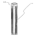
- the cylindrical lithium ion secondary battery 10 includes an electrode group 23 formed by winding a negative electrode 11, a positive electrode 12, and a separator 13 separating them, and an electrolyte having lithium ion conductivity (hereinafter simply referred to as “electrolyte”). With.
- the electrode group 23 and the electrolytic solution are accommodated in the battery case 14.
- a negative electrode lead 19 and a positive electrode lead 20 is connected to the negative electrode 11 and the positive electrode 12, respectively.
- the negative electrode lead 19 is connected to the battery case 14, and the positive electrode lead 20 is connected to the sealing body 5 and led out of the battery case 14.
- the battery case 14 is made of metal, and its opening 21 is sealed by a gasket 22 made of a resin material and a sealing body 5 having a mechanism for reducing the pressure increase inside the battery, and functions as a positive electrode terminal.
- the sealing body 5 includes a cap-shaped upper lid 2, a ring 1 having a through hole, a valve body 4, and a lower lid 3, and the ring 1 is in contact with a collar portion of the upper lid 2 to close the through hole of the ring 1.
- the valve body 4 is in contact with the lower surface of the ring 1
- the lower lid 3 is in contact with the lower surface of the valve body 4. That is, the valve body 4 is sandwiched between the ring 1 and the lower lid 3, and the lower lid 3 and the upper lid 2 are caulked and fixed so as to be electrically connected, and the sealing body 5 has a function as a positive electrode terminal. .
- An electrolytic solution is injected from the opening 21 of the battery case 14, the electrolytic solution is immersed in the electrode group 23, and the sealing body 5 and the gasket 22 are inserted into the opening 21 and fixed by caulking to form a sealed cylindrical lithium ion battery. Is done.
- Example 1 [Production of positive electrode] An N-methyl-2-pyrrolidone (NMP) solution containing lithium cobaltate as a positive electrode active material, acetylene black powder, and polyvinylidene fluoride in a mass ratio of 95: 2.5: 2.5 The mixture was kneaded in a positive electrode mixture slurry. Next, the positive electrode mixture slurry was uniformly applied to both surfaces of a positive electrode current collector made of an aluminum foil, dried, and rolled with a rolling roller to produce a positive electrode 12.
- NMP N-methyl-2-pyrrolidone
- Lithium hexafluorophosphate LiPF 6
- EC ethylene carbonate
- MEC methyl ethyl carbonate
- DEC diethyl carbonate
- a non-aqueous electrolyte was prepared by dissolving to a concentration of 0 mol / liter.
- the ring 1 has a through hole 1a (opening area ratio: 0.35), a protrusion 1b protruding toward the inside of the through hole (protrusion tip angle (1f): 90 °, protrusion height (1c): 0. 37 mm) in rotational symmetry, and the ridgeline of the protrusion 1b is formed by a straight line.
- the height 1c of the protrusion is a height of a triangle having two sides with the protrusion 1b formed by a straight ridge line 1d as the apex and a left and right semicircular tangent line 1e that is in contact with the two sides and formed as a base. Say it.
- valve body 4 is arranged on the upper surface of the lower lid 3
- the ring 1 is arranged on the upper surface of the valve body 4
- the upper lid 2 is arranged on the upper surface of the ring 1.
- a sealing body 5 was obtained.
- Electrode group For production of the electrode group, one positive electrode, one negative electrode, and two separators made of a polyethylene microporous film were used. First, a lead was attached to each of the positive and negative electrodes, the positive electrode 12 and the negative electrode 11 were made to face each other in a state of being insulated from each other via the separator 13, and wound in a spiral shape using a winding core to produce an electrode group 23.
- the electrode group 23 thus prepared and the electrolytic solution are inserted into the battery case 14 having an outer diameter of 4.5 mm and a wall thickness of 0.1 mm, and the sealing body 5 is inserted into the opening of the battery case 14 via the gasket 22. After that, the battery 1 was produced by caulking and sealing.
- Example 2 A battery 2 was prepared by setting the number of protrusions to two, the ratio of the opening area of the ring, the tip angle of the protrusion, and the height of the protrusion in the same manner as the battery 1.
- the battery 3 was manufactured by setting the number of protrusions to 6 and the ratio of the opening area of the ring, the tip angle of the protrusion, and the protrusion height in the same manner as the battery 1.
- the battery 4 was manufactured by setting the number of protrusions to eight, the ratio of the opening area of the ring, the tip angle of the protrusion, and the protrusion height in the same manner as the battery 1.
- the battery 5 was manufactured by setting the number of protrusions to one, the ratio of the opening area of the ring, the tip angle of the protrusions, and the protrusion height in the same manner as the battery 1.
- the battery 6 was manufactured by setting the number of protrusions to 0 and making the ring opening area ratio the same as that of the battery 1.
- Example 7 A battery 7 having a battery case outer diameter of 10 mm and a ring opening area ratio, the number of protrusions, the tip angle of the protrusions, and the height of the protrusions similar to that of the battery 1 was designated as battery 7.
- a battery 8 having a battery case outer diameter of 18 mm, a battery height of 65 mm, a ring opening area ratio, the number of protrusions, the tip angle of the protrusions, and a protrusion height in the same manner as the battery 1 was designated as battery 8.
- a battery 9 was manufactured by setting the ratio of the opening area of the ring to 0.2, the number of protrusions, the tip angle of the protrusions, and the height of the protrusions in the same manner as the battery 1.
- the battery 10 was manufactured by setting the ratio of the opening area of the ring to 0.7, the number of protrusions, the tip angle of the protrusions, and the height of the protrusions in the same manner as the battery 1.
- the battery 11 was manufactured by setting the opening area ratio of the ring to 0.1, the height of the protrusion to 0.24 mm, the number of protrusions, and the tip angle of the protrusion in the same manner as the battery 1.
- a battery 12 was prepared by setting the tip angle of the protrusions to 30 °, the ring opening area ratio, the number of protrusions, and the protrusion height in the same manner as the battery 1.
- the battery 13 was manufactured by setting the tip angle of the protrusion to 60 °, the ring opening area ratio, the number of protrusions, and the protrusion height in the same manner as the battery 1.
- a battery 14 was prepared by setting the tip angle of the protrusions to 120 °, the ring opening area ratio, the number of protrusions, and the protrusion height in the same manner as the battery 1.
- the battery 15 was manufactured by setting the tip angle of the protrusion to 150 °, the height of the protrusion to 0.24 mm, the aperture area ratio of the ring, and the number of protrusions in the same manner as the battery 1.
- the battery 16 was manufactured by setting the height of the protrusion to 0.2 mm, and making the ring opening area ratio, the number of protrusions, and the tip angle of the protrusion in the same manner as the battery 1.
- Example 17 A battery 17 having a protrusion height of 0.5 mm and a ring opening area ratio, the number of protrusions, and the tip angle of the protrusions similar to the battery 1 was designated as battery 17.
- the battery 18 was manufactured by setting the height of the protrusion to 0.8 mm and making the ring opening area ratio, the number of protrusions, and the tip angle of the protrusion in the same manner as the battery 1.
- a battery case bottom hole is provided on the lower surface of the battery case of the manufactured battery, a pressurizer equipped with a pressure indicator is connected so as to wrap and seal the battery case bottom hole, and a battery case is connected from the battery case bottom hole using gas or liquid. 14 was pressurized, and the display value of the pressure indicator when the valve body 4 was cleaved was taken as the operating pressure.
- Table 1 shows the operating pressure and evaluation results of the valve bodies of batteries 1 to 18.
- the evaluation result is evaluated by the numerical value of the operating pressure of the valve body.
- the operating pressure of the valve body is expressed as “B” with an appropriate range of 1 MPa or more and 10 MPa or less, and in particular, the operating pressure of the valve body is 2 MPa or more and 9 MPa.
- the following was expressed as “A” as a more preferable appropriate range.
- “C” is indicated as outside the proper range.
- the operating pressure of the valve body is stable in the range of 3.8 MPa to 4.3 MPa. In this range, since an appropriate height of the protrusion and strength of the protrusion are ensured, a multi-point stress concentration is applied to the valve body when the internal pressure rises, so that a stable valve operating pressure is obtained.
- the operating pressure of the valve body is 3.8 MPa for the battery 1 and 1.2 MPa for the battery 7, both of which are abnormal.
- the pressure was sometimes able to avoid an increase in internal pressure at an early stage.
- the operating pressure of the valve body is as low as 0.4 MPa, and the battery temperature rises even during normal use of the cylindrical lithium ion secondary battery. Undesirably, the valve body is cleaved by a possible pressure.
- the battery 9 and the battery 10 when the opening area ratio of the ring is 0.2 or more and 0.7 or less, the operating pressure of the valve body is 3.8 MPa to 7.5 MPa. The pressure was enough to avoid rupture.
- the operating pressure of the valve body was 10 MPa. This is because there is a risk that sufficient pressure for cleaving the valve body may not be obtained, and depending on how the battery is used and the size of the battery, before the valve body of the sealing body operates due to gas release during valve operation, There is a risk of bursting.
- the operating pressure of the valve body is 3.7 MPa, 4 MPa, It was 5 MPa. This is presumably because the valve body is susceptible to stress concentration at the tip of the protrusion when the internal pressure rises, and the valve operating pressure is lowered and stabilized.
- the present invention it is possible to provide a small metal cylindrical lithium ion battery that has no risk of rupture of the battery container body by providing a mechanism for alleviating the pressure increase inside the battery when a battery abnormality occurs. It is useful for highly reliable wearable devices that ensure safety.
Landscapes
- Chemical & Material Sciences (AREA)
- Chemical Kinetics & Catalysis (AREA)
- Electrochemistry (AREA)
- General Chemical & Material Sciences (AREA)
- Engineering & Computer Science (AREA)
- Materials Engineering (AREA)
- Manufacturing & Machinery (AREA)
- Gas Exhaust Devices For Batteries (AREA)
- Sealing Battery Cases Or Jackets (AREA)
- Secondary Cells (AREA)
Abstract
Description
開口面積比=貫通孔面積/(リング面積+貫通孔面積)
により求められる。
図1および図2を参照しながら本発明の円筒形リチウム二次電池の一実施形態の構成を説明する。
[正極の作製]
正極活物質のコバルト酸リチウムと、アセチレンブラック粉末と、ポリフッ化ビニリデンとを、質量比で95:2.5:2.5の割合になるように、N-メチル-2-ピロリドン(NMP)溶液中で混練し正極合剤スラリーを調製した。次いで、この正極合剤スラリーを、アルミニウム箔からなる正極集電体の両面に均一に塗布し、乾燥させ、圧延ローラにより圧延することにより正極12を作製した。
負極活物質の人造黒鉛と、カルボキシメチルセルロースナトリウムと、スチレン-ブタジエンゴムとを98:1:1の質量比で水溶液中において混合し、負極合剤スラリーを調製した。次いで、この負極合剤スラリーを銅箔からなる負極集電体の両面に均一に塗布し、乾燥させ、圧延ローラにより圧延することにより負極11を得た。
エチレンカーボネート(EC)とメチルエチルカーボネート(MEC)とジエチルカーボネート(DEC)とを、3:5:2の体積比で混合した混合溶媒に対し、六フッ化リン酸リチウム(LiPF6)を1.0モル/リットルの濃度になるように溶解させて、非水電解液を調製した。
SUS板材をプレス加工して成型した上蓋2(外径:3.9mm、厚み:0.1mm)と下蓋3(外径:3.9mm、厚み:0.1mm)、変性ポリプロピレン(厚み:25μm)/アルミニウム箔(厚み:25μm)/変性ポリプロピレン(厚み:25μm)の三層ラミネート材をプレス加工して成型したフィルム状の弁体4(外径:3.5mm、厚み:75μm)、およびSUS板材をプレス加工して成型してリング1(外径:3.5mm、厚み:0.2mm)を得た。
電極群の作製には、正極を1枚、負極1枚、ポリエチレン製微多孔膜からなるセパレータ2枚を用いた。まず、正負極それぞれにリードを取り付け、正極12と負極11とをセパレータ13を介して互いに絶縁した状態で対向させ、巻き芯を用いて渦巻き状に巻回して電極群23を作製した。
突起の数を2個とし、リングの開口面積比、突起の先端角度、突起高さを電池1と同様にして作製した電池を電池2とした。
突起の数を6個とし、リングの開口面積比、突起の先端角度、突起高さを電池1と同様にして作製した電池を電池3とした。
突起の数を8個とし、リングの開口面積比、突起の先端角度、突起高さを電池1と同様にして作製した電池を電池4とした。
突起の数を1個とし、リングの開口面積比、突起の先端角度、突起高さを電池1と同様にして作製した電池を電池5とした。
突起の数を0個とし、リングの開口面積比を電池1と同様にして作製した電池を電池6とした。
電池ケース外径を10mmとし、リングの開口面積比、突起の数、突起の先端角度、突起高さを電池1と同様にして作製した電池を電池7とした。
電池ケース外径を18mm、電池高さを65mmとし、リングの開口面積比、突起の数、突起の先端角度、突起高さを電池1と同様にして作製した電池を電池8とした。
リングの開口面積比を0.2とし、突起の数、突起の先端角度、突起高さを電池1と同様にして作製した電池を電池9とした。
リングの開口面積比を0.7とし、突起の数、突起の先端角度、突起高さを電池1と同様にして作製した電池を電池10とした。
リングの開口面積比を0.1、突起の高さを0.24mmとし、突起の数、突起の先端角度を電池1と同様にして作製した電池を電池11とした。
突起の先端角度を30°とし、リングの開口面積比、突起の数、突起高さを電池1と同様にして作製した電池を電池12とした。
突起の先端角度を60°とし、リングの開口面積比、突起の数、突起高さを電池1と同様にして作製した電池を電池13とした。
突起の先端角度を120°とし、リングの開口面積比、突起の数、突起高さを電池1と同様にして作製した電池を電池14とした。
突起の先端角度を150°、突起の高さを0.24mmとし、リングの開口面積比、突起の数を電池1と同様にして作製した電池を電池15とした。
突起の高さを0.2mmとし、リングの開口面積比、突起の数、突起の先端角度を電池1と同様にして作製した電池を電池16とした。
突起の高さを0.5mmとし、リングの開口面積比、突起の数、突起の先端角度を電池1と同様にして作製した電池を電池17とした。
突起の高さを0.8mmとし、リングの開口面積比、突起の数、突起の先端角度を電池1と同様にして作製した電池を電池18とした。
作製した電池の電池ケース下面に電池ケース底穴を設け、電池ケース底穴を包み密閉するように、圧力表示器を備えた加圧器を接続し、ガス又は液体を用い電池ケース底穴から電池ケース14の内側を加圧し、弁体4が開裂した際の圧力表示器の表示値を作動圧とした。

1a 貫通孔
1b 突起
1c 突起の高さ
1d 稜線
1e 半円形状の接線
1f 突起先端角度
2 上蓋
2a 上蓋内高さ
3 下蓋
4 弁体
5 封口体
10 円筒形リチウムイオン二次電池
11 負極
12 正極
13 セパレータ
14 電池ケース
19 負極リード
20 正極リード
21 開口部
22 ガスケット
23 電極群
Claims (9)
- 正極と負極との間にセパレータを介して巻回または積層して構成した電極群と、電解液とを電池ケースに収容し、封口体によって封口した円筒形リチウムイオン二次電池であって、
前記電池ケースの外径が10mm以下であり、
前記封口体が、貫通孔を有するリングと、前記リングの貫通孔を塞ぐように設置されたシート状あるいはフィルム状の弁体とを有し、電池内部が所定圧力に達したときに前記弁体が開裂する安全機構を備え、
前記リングが、貫通孔内方に向かって突出する複数の突起を有し、
前記突起が、直線の稜線で構成された円筒形リチウムイオン二次電池。 - 前記貫通孔の開口面積比が0.2以上、0.7以下である請求項1に記載の円筒形リチウムイオン二次電池。
- 前記リングの材質が、金属、セラミックスおよび金属化合物からなる群より選択される少なくとも一種である請求項1または2に記載の円筒形リチウムイオン二次電池。
- 前記弁体が、樹脂と金属の積層体である請求項1~3のいずれかに記載の円筒形リチウムイオン二次電池。
- 前記リングが、2個以上、8個以下の突起を有する請求項1~4のいずれかに記載の円筒形リチウムイオン二次電池。
- 前記突起が、回転対称に配置されている請求項1~5のいずれかに記載の円筒形リチウムイオン二次電池。
- 前記突起の先端角度が、60°以上、120°以下である請求項1~6のいずれかに記載の円筒形リチウムイオン二次電池。
- 前記突起の高さが、0.25mm以上、2.5mm以下である請求項1~7のいずれかに記載の円筒形リチウムイオン二次電池。
- 前記所定圧力が、1MPa以上、10MPa以下である請求項1~8のいずれかに記載の円筒形リチウムイオン二次電池。
Priority Applications (3)
| Application Number | Priority Date | Filing Date | Title |
|---|---|---|---|
| JP2016523152A JP6731580B2 (ja) | 2014-05-30 | 2015-05-27 | 円筒形リチウムイオン二次電池 |
| US15/310,192 US10305077B2 (en) | 2014-05-30 | 2015-05-27 | Cylindrical lithium-ion secondary battery |
| CN201580022368.0A CN106256030B (zh) | 2014-05-30 | 2015-05-27 | 圆筒形锂离子二次电池 |
Applications Claiming Priority (2)
| Application Number | Priority Date | Filing Date | Title |
|---|---|---|---|
| JP2014-112098 | 2014-05-30 | ||
| JP2014112098 | 2014-05-30 |
Publications (1)
| Publication Number | Publication Date |
|---|---|
| WO2015182136A1 true WO2015182136A1 (ja) | 2015-12-03 |
Family
ID=54698482
Family Applications (1)
| Application Number | Title | Priority Date | Filing Date |
|---|---|---|---|
| PCT/JP2015/002681 Ceased WO2015182136A1 (ja) | 2014-05-30 | 2015-05-27 | 円筒形リチウムイオン二次電池 |
Country Status (4)
| Country | Link |
|---|---|
| US (1) | US10305077B2 (ja) |
| JP (1) | JP6731580B2 (ja) |
| CN (1) | CN106256030B (ja) |
| WO (1) | WO2015182136A1 (ja) |
Cited By (3)
| Publication number | Priority date | Publication date | Assignee | Title |
|---|---|---|---|---|
| WO2020075731A1 (ja) * | 2018-10-09 | 2020-04-16 | 大日本印刷株式会社 | 電池用弁体、その製造方法及び電池 |
| US11024922B2 (en) * | 2017-03-23 | 2021-06-01 | Lg Chem, Ltd. | Cap assembly comprising guide member for preventing escape of safety vent |
| WO2021215500A1 (ja) | 2020-04-23 | 2021-10-28 | 株式会社村田製作所 | 二次電池 |
Families Citing this family (2)
| Publication number | Priority date | Publication date | Assignee | Title |
|---|---|---|---|---|
| US11742542B2 (en) * | 2019-04-02 | 2023-08-29 | Changzhou Microbat Technology Co. Ltd. | Explosion-proof enclosure for energy storage device and energy storage device |
| CN116454529B (zh) * | 2023-06-14 | 2023-09-08 | 深圳海辰储能控制技术有限公司 | 顶盖组件及电池 |
Citations (4)
| Publication number | Priority date | Publication date | Assignee | Title |
|---|---|---|---|---|
| JPH07130346A (ja) * | 1993-11-04 | 1995-05-19 | Sony Corp | 非水電解液二次電池 |
| JPH10172528A (ja) * | 1996-12-05 | 1998-06-26 | Sony Corp | 非水電解液電池 |
| JP2009193862A (ja) * | 2008-02-15 | 2009-08-27 | Komatsulite Mfg Co Ltd | 電池用安全装置 |
| JP2014071987A (ja) * | 2012-09-28 | 2014-04-21 | Panasonic Corp | 円筒形リチウムイオン二次電池 |
Family Cites Families (11)
| Publication number | Priority date | Publication date | Assignee | Title |
|---|---|---|---|---|
| JPH03116651A (ja) | 1989-09-29 | 1991-05-17 | Toshiba Battery Co Ltd | 角形密閉式電池 |
| US6083639A (en) | 1997-08-22 | 2000-07-04 | Duracell Inc. | Current interrupter for electrochemical cells |
| JP2000036294A (ja) * | 1998-07-21 | 2000-02-02 | Mitsubishi Alum Co Ltd | 電池、電池容器材、及び電池容器材の製造方法 |
| US6495284B2 (en) * | 2001-02-12 | 2002-12-17 | The Gillette Company | End seal assembly for an alkaline cell |
| JP2004014217A (ja) * | 2002-06-05 | 2004-01-15 | Japan Storage Battery Co Ltd | 非水電解質二次電池 |
| JP4222820B2 (ja) * | 2002-11-21 | 2009-02-12 | パナソニック株式会社 | 電池用安全機構の製造方法 |
| CN100588000C (zh) | 2008-03-25 | 2010-02-03 | 无锡瑞通电源有限公司 | 安全锂电池壳 |
| WO2010100731A1 (ja) * | 2009-03-04 | 2010-09-10 | トヨタ自動車株式会社 | 密閉型電池及び密閉型電池の製造方法 |
| CN201556648U (zh) | 2009-06-03 | 2010-08-18 | 包雄伟 | 一种可充电电池的顶盖及其包装壳 |
| WO2012111744A1 (ja) * | 2011-02-18 | 2012-08-23 | 新神戸電機株式会社 | 非水電解液二次電池 |
| JP5776005B2 (ja) * | 2011-09-29 | 2015-09-09 | パナソニックIpマネジメント株式会社 | 密閉型二次電池 |
-
2015
- 2015-05-27 JP JP2016523152A patent/JP6731580B2/ja active Active
- 2015-05-27 WO PCT/JP2015/002681 patent/WO2015182136A1/ja not_active Ceased
- 2015-05-27 US US15/310,192 patent/US10305077B2/en active Active
- 2015-05-27 CN CN201580022368.0A patent/CN106256030B/zh active Active
Patent Citations (4)
| Publication number | Priority date | Publication date | Assignee | Title |
|---|---|---|---|---|
| JPH07130346A (ja) * | 1993-11-04 | 1995-05-19 | Sony Corp | 非水電解液二次電池 |
| JPH10172528A (ja) * | 1996-12-05 | 1998-06-26 | Sony Corp | 非水電解液電池 |
| JP2009193862A (ja) * | 2008-02-15 | 2009-08-27 | Komatsulite Mfg Co Ltd | 電池用安全装置 |
| JP2014071987A (ja) * | 2012-09-28 | 2014-04-21 | Panasonic Corp | 円筒形リチウムイオン二次電池 |
Cited By (6)
| Publication number | Priority date | Publication date | Assignee | Title |
|---|---|---|---|---|
| US11024922B2 (en) * | 2017-03-23 | 2021-06-01 | Lg Chem, Ltd. | Cap assembly comprising guide member for preventing escape of safety vent |
| WO2020075731A1 (ja) * | 2018-10-09 | 2020-04-16 | 大日本印刷株式会社 | 電池用弁体、その製造方法及び電池 |
| JPWO2020075731A1 (ja) * | 2018-10-09 | 2021-09-16 | 大日本印刷株式会社 | 電池用弁体、その製造方法及び電池 |
| JP7359155B2 (ja) | 2018-10-09 | 2023-10-11 | 大日本印刷株式会社 | 電池用弁体、その製造方法及び電池 |
| WO2021215500A1 (ja) | 2020-04-23 | 2021-10-28 | 株式会社村田製作所 | 二次電池 |
| EP4142011A4 (en) * | 2020-04-23 | 2025-03-05 | Murata Manufacturing Co., Ltd. | SECONDARY BATTERY |
Also Published As
| Publication number | Publication date |
|---|---|
| CN106256030B (zh) | 2020-12-29 |
| JP6731580B2 (ja) | 2020-07-29 |
| US20170141370A1 (en) | 2017-05-18 |
| JPWO2015182136A1 (ja) | 2017-04-20 |
| US10305077B2 (en) | 2019-05-28 |
| CN106256030A (zh) | 2016-12-21 |
Similar Documents
| Publication | Publication Date | Title |
|---|---|---|
| CN111448687B (zh) | 二次电池 | |
| JP4470124B2 (ja) | 電池 | |
| US10128485B2 (en) | Sealed secondary battery | |
| CN101689675B (zh) | 锂二次电池 | |
| CN107431179B (zh) | 圆筒形电池 | |
| JP5899495B2 (ja) | 円筒形リチウムイオン電池 | |
| JPWO2016157749A1 (ja) | 円筒形電池 | |
| JP6731580B2 (ja) | 円筒形リチウムイオン二次電池 | |
| US10340499B2 (en) | Sealed secondary battery | |
| CN210224213U (zh) | 具有一体化绝缘极耳的卷绕型纽扣电池 | |
| JPWO2016143287A1 (ja) | 密閉型電池 | |
| CN108886129A (zh) | 圆筒形电池 | |
| JPWO2013046712A1 (ja) | 密閉型二次電池 | |
| JP2016126975A (ja) | 円筒形電池 | |
| JP2008204839A (ja) | 円筒形電池用封口板 | |
| EP4300644A1 (en) | Cylindrical battery | |
| JP2016009558A (ja) | 円筒形電池 | |
| CN201069809Y (zh) | 一种柱形锂离子电池结构 | |
| JP4929619B2 (ja) | 円柱状リチウム二次電池 | |
| JP2014107054A (ja) | 密閉型電池 | |
| WO2013018606A1 (ja) | 角形密閉電池 | |
| KR101584301B1 (ko) | 전극 탭 제조 방법 및 전극 리드 제조 방법 | |
| KR20150033276A (ko) | 전극조립체 및 전지케이스간의 결합력이 향상된 이차전지 | |
| JP2012178229A (ja) | 密閉電池 | |
| JP2010080390A (ja) | 電池 |
Legal Events
| Date | Code | Title | Description |
|---|---|---|---|
| 121 | Ep: the epo has been informed by wipo that ep was designated in this application |
Ref document number: 15800446 Country of ref document: EP Kind code of ref document: A1 |
|
| ENP | Entry into the national phase |
Ref document number: 2016523152 Country of ref document: JP Kind code of ref document: A |
|
| WWE | Wipo information: entry into national phase |
Ref document number: 15310192 Country of ref document: US |
|
| NENP | Non-entry into the national phase |
Ref country code: DE |
|
| 122 | Ep: pct application non-entry in european phase |
Ref document number: 15800446 Country of ref document: EP Kind code of ref document: A1 |