WO2015178134A1 - Unité de capture d'image et endoscope - Google Patents
Unité de capture d'image et endoscope Download PDFInfo
- Publication number
- WO2015178134A1 WO2015178134A1 PCT/JP2015/061636 JP2015061636W WO2015178134A1 WO 2015178134 A1 WO2015178134 A1 WO 2015178134A1 JP 2015061636 W JP2015061636 W JP 2015061636W WO 2015178134 A1 WO2015178134 A1 WO 2015178134A1
- Authority
- WO
- WIPO (PCT)
- Prior art keywords
- optical member
- light
- cover glass
- end surface
- holding frame
- Prior art date
Links
Images


Classifications
-
- G—PHYSICS
- G02—OPTICS
- G02B—OPTICAL ELEMENTS, SYSTEMS OR APPARATUS
- G02B23/00—Telescopes, e.g. binoculars; Periscopes; Instruments for viewing the inside of hollow bodies; Viewfinders; Optical aiming or sighting devices
- G02B23/24—Instruments or systems for viewing the inside of hollow bodies, e.g. fibrescopes
- G02B23/2407—Optical details
- G02B23/2423—Optical details of the distal end
- G02B23/243—Objectives for endoscopes
-
- A—HUMAN NECESSITIES
- A61—MEDICAL OR VETERINARY SCIENCE; HYGIENE
- A61B—DIAGNOSIS; SURGERY; IDENTIFICATION
- A61B1/00—Instruments for performing medical examinations of the interior of cavities or tubes of the body by visual or photographical inspection, e.g. endoscopes; Illuminating arrangements therefor
- A61B1/00064—Constructional details of the endoscope body
- A61B1/00071—Insertion part of the endoscope body
- A61B1/0008—Insertion part of the endoscope body characterised by distal tip features
- A61B1/00096—Optical elements
-
- A—HUMAN NECESSITIES
- A61—MEDICAL OR VETERINARY SCIENCE; HYGIENE
- A61B—DIAGNOSIS; SURGERY; IDENTIFICATION
- A61B1/00—Instruments for performing medical examinations of the interior of cavities or tubes of the body by visual or photographical inspection, e.g. endoscopes; Illuminating arrangements therefor
- A61B1/00112—Connection or coupling means
- A61B1/00114—Electrical cables in or with an endoscope
-
- A—HUMAN NECESSITIES
- A61—MEDICAL OR VETERINARY SCIENCE; HYGIENE
- A61B—DIAGNOSIS; SURGERY; IDENTIFICATION
- A61B1/00—Instruments for performing medical examinations of the interior of cavities or tubes of the body by visual or photographical inspection, e.g. endoscopes; Illuminating arrangements therefor
- A61B1/005—Flexible endoscopes
- A61B1/0051—Flexible endoscopes with controlled bending of insertion part
- A61B1/0052—Constructional details of control elements, e.g. handles
-
- A—HUMAN NECESSITIES
- A61—MEDICAL OR VETERINARY SCIENCE; HYGIENE
- A61B—DIAGNOSIS; SURGERY; IDENTIFICATION
- A61B1/00—Instruments for performing medical examinations of the interior of cavities or tubes of the body by visual or photographical inspection, e.g. endoscopes; Illuminating arrangements therefor
- A61B1/04—Instruments for performing medical examinations of the interior of cavities or tubes of the body by visual or photographical inspection, e.g. endoscopes; Illuminating arrangements therefor combined with photographic or television appliances
- A61B1/05—Instruments for performing medical examinations of the interior of cavities or tubes of the body by visual or photographical inspection, e.g. endoscopes; Illuminating arrangements therefor combined with photographic or television appliances characterised by the image sensor, e.g. camera, being in the distal end portion
-
- A—HUMAN NECESSITIES
- A61—MEDICAL OR VETERINARY SCIENCE; HYGIENE
- A61B—DIAGNOSIS; SURGERY; IDENTIFICATION
- A61B1/00—Instruments for performing medical examinations of the interior of cavities or tubes of the body by visual or photographical inspection, e.g. endoscopes; Illuminating arrangements therefor
- A61B1/06—Instruments for performing medical examinations of the interior of cavities or tubes of the body by visual or photographical inspection, e.g. endoscopes; Illuminating arrangements therefor with illuminating arrangements
- A61B1/0661—Endoscope light sources
- A61B1/0676—Endoscope light sources at distal tip of an endoscope
-
- G—PHYSICS
- G02—OPTICS
- G02B—OPTICAL ELEMENTS, SYSTEMS OR APPARATUS
- G02B13/00—Optical objectives specially designed for the purposes specified below
-
- G—PHYSICS
- G02—OPTICS
- G02B—OPTICAL ELEMENTS, SYSTEMS OR APPARATUS
- G02B23/00—Telescopes, e.g. binoculars; Periscopes; Instruments for viewing the inside of hollow bodies; Viewfinders; Optical aiming or sighting devices
- G02B23/24—Instruments or systems for viewing the inside of hollow bodies, e.g. fibrescopes
- G02B23/2407—Optical details
- G02B23/2446—Optical details of the image relay
-
- G—PHYSICS
- G02—OPTICS
- G02B—OPTICAL ELEMENTS, SYSTEMS OR APPARATUS
- G02B23/00—Telescopes, e.g. binoculars; Periscopes; Instruments for viewing the inside of hollow bodies; Viewfinders; Optical aiming or sighting devices
- G02B23/24—Instruments or systems for viewing the inside of hollow bodies, e.g. fibrescopes
- G02B23/2476—Non-optical details, e.g. housings, mountings, supports
-
- G—PHYSICS
- G02—OPTICS
- G02B—OPTICAL ELEMENTS, SYSTEMS OR APPARATUS
- G02B5/00—Optical elements other than lenses
- G02B5/005—Diaphragms
-
- G—PHYSICS
- G02—OPTICS
- G02B—OPTICAL ELEMENTS, SYSTEMS OR APPARATUS
- G02B7/00—Mountings, adjusting means, or light-tight connections, for optical elements
- G02B7/02—Mountings, adjusting means, or light-tight connections, for optical elements for lenses
-
- H—ELECTRICITY
- H04—ELECTRIC COMMUNICATION TECHNIQUE
- H04N—PICTORIAL COMMUNICATION, e.g. TELEVISION
- H04N23/00—Cameras or camera modules comprising electronic image sensors; Control thereof
- H04N23/56—Cameras or camera modules comprising electronic image sensors; Control thereof provided with illuminating means
-
- A—HUMAN NECESSITIES
- A61—MEDICAL OR VETERINARY SCIENCE; HYGIENE
- A61B—DIAGNOSIS; SURGERY; IDENTIFICATION
- A61B1/00—Instruments for performing medical examinations of the interior of cavities or tubes of the body by visual or photographical inspection, e.g. endoscopes; Illuminating arrangements therefor
- A61B1/00163—Optical arrangements
- A61B1/00186—Optical arrangements with imaging filters
-
- H—ELECTRICITY
- H04—ELECTRIC COMMUNICATION TECHNIQUE
- H04N—PICTORIAL COMMUNICATION, e.g. TELEVISION
- H04N23/00—Cameras or camera modules comprising electronic image sensors; Control thereof
- H04N23/50—Constructional details
- H04N23/555—Constructional details for picking-up images in sites, inaccessible due to their dimensions or hazardous conditions, e.g. endoscopes or borescopes
Definitions
- the present invention relates to an imaging unit and an endoscope including an objective lens unit and an imaging device.
- An imaging unit for capturing an optical image is provided in the distal end of an insertion part that can be inserted from the outside of the living body or structure to observe a difficult part such as the inside of the living body or the inside of the structure.
- the provided endoscope is used in the medical field and the industrial field, for example.
- an imaging unit of an endoscope is disposed on an objective lens unit that forms a subject image and an imaging surface of the objective lens unit.
- An image sensor is provided.
- a cover glass 23 that seals the light receiving surface 22 a is fixed on the light receiving surface 22 a of the image sensor 22.
- An optical member 24 made of a transparent member such as glass is attached to the front surface of the cover glass 23.
- the optical member 24 is fitted into a fitting hole 21a formed in the holding frame 21 fixed to an objective lens unit (not shown), and is fixed by an adhesive or the like.
- some imaging units have a configuration in which the imaging element 22 is fixed to the holding frame 21 fixed to the objective lens unit via the optical member 24.
- An imaging unit having an optical member 24 fitted to the rear end of the holding frame 21 fixed to the objective lens unit and an imaging device 22 fixed to the optical member 24 as shown in FIG.
- it is necessary to reduce the outer shape of the optical member 24. If the outer shape of the optical member 24 is reduced, the outer shape of the rear end portion of the holding frame 21 can also be reduced.
- the side surface of the optical member 24 approaches the optical axis. For this reason, as shown as a two-dot chain line segment L10 in FIG. 13, the light beam reflected on the side surface of the optical member 24 enters the pixel formation region 22b of the image sensor 22 and causes flare.
- the light shielding member 25 is disposed on the rear surface (image side surface) of the optical member 24, the light beam L10 reflected on the side surface of the optical member 24 can be blocked.
- the light beam L11 reflected on the projection 21b provided on the holding frame 21 for abutting the optical member 24 is incident on the pixel formation region 22b of the image sensor 22 and causes flare. .
- the imaging unit becomes larger (larger diameter).
- the present invention has been made in view of the above-described points, and an object of the present invention is to provide an imaging unit and an endoscope that achieve both miniaturization and flare suppression.
- the imaging unit of one embodiment of the present invention is an objective lens unit, a cover glass that is a rectangle or a square fixed on a light receiving surface that is a front end surface of an image sensor, and is attached to a front end surface of the cover glass, A circular optical member having a diameter smaller than the diagonal length of the cover glass, a holding frame fixed to the objective lens unit having a circular fitting hole into which the optical member is fitted from behind, and in the holding frame A first light-shielding member that is disposed in front of the optical member and that reflects off an inner wall surface of the protrusion and blocks out-of-field light toward the pixel formation region of the image sensor, And a second light-shielding member that is disposed between the rear end surface of the optical member and the front end surface of the cover glass, and reflects off-field light reflected at a side surface of the optical member and directed into the pixel formation region, Provided.
- An endoscope according to an aspect of the present invention includes the imaging unit.
- FIG. 5 is a VV cross-sectional view of FIG. 3. It is VI-VI sectional drawing of FIG. It is VII-VII sectional drawing of FIG. It is a figure which shows each external shape of the rear end part of a holding frame, an optical member, a cover glass, and an image pick-up device when it sees from the front. It is IX-IX sectional drawing of FIG. It is XX sectional drawing of FIG.
- the endoscope 101 of the present embodiment has a configuration that can be introduced into a subject such as a human body and can optically image a predetermined observation site in the subject.
- the subject into which the endoscope 101 is introduced is not limited to a human body, and may be another living body or an artificial object such as a machine or a building.
- the endoscope 101 of the present embodiment includes an elongated insertion portion 102 introduced into the subject, an operation portion 103 located at the proximal end of the insertion portion 102, and a side portion of the operation portion 103.
- the universal code 104 is mainly configured.
- the insertion portion 102 is provided at the distal end portion 110 disposed at the distal end, the bendable bending portion 109 disposed on the proximal end side of the distal end portion 110, and the proximal end side of the bending portion 109.
- a flexible tube portion 108 having flexibility and connected to the distal end side is continuously provided.
- An imaging unit 1 including the objective lens unit 10 and the imaging element 2 is disposed at the distal end portion 110.
- the distal end portion 110 is also provided with an illumination light emitting portion that emits light that illuminates the subject of the imaging unit 1.
- the endoscope 101 may have a so-called rigid endoscope that does not include a flexible portion in the insertion portion.
- the operation unit 103 disposed at the proximal end of the insertion unit 102 is provided with an angle operation knob 106 for operating the bending of the bending unit 109.
- An endoscope connector 105 configured to be connectable to the external device 120 is provided at the base end portion of the universal cord 104.
- the external device 120 to which the endoscope connector 105 is connected includes a camera control unit 120a.
- a transmission cable 115 inserted in the insertion unit 102, the operation unit 103, and the universal cord 104 is disposed.
- the transmission cable 115 is configured to electrically connect the imaging unit 1 and the connector unit 105.
- the imaging unit 1 is electrically connected to the camera control unit 120 a of the external device 120 via the transmission cable 115.
- power is supplied from the external device 120 to the imaging unit 1, and signals are exchanged between the external device 120 and the imaging unit 1.
- the camera control unit 120 a has a configuration that generates a video based on the signal output from the imaging unit 1 and outputs the video to the image display unit 121. That is, in the present embodiment, the optical image captured by the imaging unit 1 is displayed on the image display unit 121 as a video. Note that a part or all of the camera control unit 120 a and the image display unit 121 may be configured integrally with the endoscope 101.
- FIG. 2 is a cross-sectional view of the imaging unit 1.
- the imaging unit 1 includes an objective lens unit 10 and an imaging element 2.
- the objective lens unit 10 includes a plurality of optical elements such as lenses, filters, and diaphragms, and is configured to form a subject image on an image plane.
- the objective lens unit 10 is constituted by a plurality of lenses 10 a arranged on a linear optical axis O.
- the direction toward the object side (subject side) along the optical axis O is referred to as the front, and the direction toward the opposite image side is referred to as the rear.
- the objective lens unit 10 may include an optical element having a reflecting surface such as a mirror or a prism, and the optical axis O may be bent on the reflecting surface.
- the plurality of lenses 10 a are fixed in a cylindrical lens barrel 11.
- a holding frame 12 is fixed to the rear end of the lens barrel 11.
- the holding frame 12 is a cylindrical member.
- the front end portion of the holding frame 12 is fitted to the rear end portion of the lens barrel 11.
- a disc-shaped optical member 13 is fitted inside the rear end of the holding frame 12. Details of the holding frame 12 and the optical member 13 will be described later.
- the imaging device 2 is, for example, a CCD, a MOS image sensor, a CMOS image sensor, or the like.
- the imaging device 2 has a light receiving surface 2a on which a plurality of pixels made of photodiodes are arranged.
- a cover glass 3 for sealing the light receiving surface 2a is attached on the light receiving surface 2a of the image pickup device 2.
- the cover glass 3 is also referred to as lid glass or the like.
- the front surface of the cover glass 3 is bonded to the rear surface of the optical member 13 with an adhesive. That is, the image sensor 2 is fixed to the holding frame 12 via the cover glass 3 and the optical member 13.
- FIG. 3 is an enlarged cross-sectional view of the rear end portion of the holding frame 12 of the imaging unit 1, the optical member 13, the cover glass 3, and the imaging element 2.
- FIG. 4 is a front view of the light receiving surface 2 a of the image sensor 2.
- 5 is a cross-sectional view taken along the line VV in FIG. 6 is a cross-sectional view taken along the line VI-VI in FIG. 7 is a sectional view taken along line VII-VII in FIG.
- the pixel formation region 2b is, for example, a rectangle or a square.
- the camera control unit 120a does not generate an image to be displayed on the image display unit 121 using all the pixels in the pixel formation region 2b of the image sensor 2, but a part of the pixel formation region 2b.
- a video to be displayed on the image display unit 121 is generated using pixels in the area.
- an area composed of pixels used for signal generation for generating the video is defined as a display area 2c.
- the display area 2c is an octagon. More specifically, the display area 2c has four outer sides parallel to the outer shape of the pixel forming area 2b that is rectangular or square. The display area 2c has a shape in which the four corners of the four-sided shape composed of the four outer sides are cut off by straight lines.
- the image sensor 2 is disposed so that the center of the display area 2c is positioned on the optical axis O. In the present embodiment, the center of the pixel formation region 2b and the center of the display region 2c coincide.
- the image sensor 2 When the optical image formed in the display area 2c is converted into an image displayed on the image display unit 121, the image sensor 2 outputs only signals from pixels located in the display area 2c.
- a mode in which the drive mode of the image sensor 2 is set may be used, or after reading signals output from all the pixels of the image sensor 2, an image of an area corresponding to the display area 2 c is obtained by image processing.
- the form to cut out may be used.
- the center of the pixel formation region 2b and the center of the display region 2c do not have to coincide with each other.
- the aspect ratio of the pixel formation region 2b and the aspect ratio of the display region 2c may not be the same.
- a cover glass 3 is fixed on the light receiving surface 2a of the image pickup device 2.
- the cover glass 3 is a member that seals the pixel formation region 2b.
- the cover glass 3 is a flat plate that is rectangular or square when viewed from a direction parallel to the optical axis O.
- the cover glass 3 has an outer shape larger than the pixel formation region 2b when viewed from a direction parallel to the optical axis O.
- the cover glass 3 has four outer sides parallel to the outer shape of the pixel formation region 2b and covers the entire pixel formation region 2b when viewed from a direction parallel to the optical axis O. It is arranged. The center of the cover glass 3 is located on the optical axis O.
- the optical member 13 is fixed on the surface of the cover glass 3 opposite to the imaging device 2, that is, on the front surface of the cover glass 3.
- the optical member 13 is a flat plate made of a transparent material such as glass and having a circular shape when viewed from a direction parallel to the optical axis O.
- the optical member 13 having a disc shape is arranged so that the center is located on the optical axis O.
- the diameter D of the optical member 13 is smaller than the diagonal length L of the cover glass 3 that is rectangular or square.
- the diameter D of the optical member 13 is a value that covers the entire display region 2c when viewed from a direction parallel to the optical axis O.
- the protrusion from the external shape of the cover glass 3 of the optical member 13 is made small by making the diameter D of the optical member 13 that is circular smaller than the diagonal length L of the cover glass 3 that is rectangular or square.
- the imaging unit 1 can be downsized.
- a fitting hole 12 a is formed at the rear end of the holding frame 12.
- the rear end of the cylindrical holding frame 12 has a shape cut off by a plane perpendicular to the optical axis O.
- the fitting hole 12a is a circular hole centered on the optical axis O.
- the fitting hole 12a has an inner diameter into which the disc-shaped optical member 13 is fitted.
- the optical member 13 is inserted into the fitting hole 12a from the rear to the front, and is fixed by an adhesive.
- the inner wall surface of the fitting hole 12a is provided with a protruding portion 12b that protrudes inward in the radial direction of the fitting hole 12a.
- the protruding portion 12b is a portion for positioning the optical member 13 in a direction parallel to the optical axis O.
- the protrusion 12b is provided over the entire circumferential direction of the inner wall surface of the fitting hole 12a.
- the protrusion 12b is provided at a predetermined distance from the rear end of the holding frame 12 in parallel to the optical axis O toward the front.
- the distance between the rear end of the holding frame 12 and the rear end of the protruding portion 12 b is shorter than the thickness of the optical member 13.
- the first light shielding member 4 and the second light shielding member 5 are disposed in contact with the front end surface 13 a of the optical member 13 and the rear end surface 13 b of the optical member 13. ing.
- the first light-shielding member 4 and the second light-shielding member 5 are members for shielding out-of-field light that enters the objective lens unit 10 from outside the field of the imaging unit 1.
- the out-of-field light is a light beam other than a light beam that passes through the objective lens unit 10 and reaches the rear end of the holding frame 12 and that forms an image in the display region 2c.
- the first light shielding member 4 and the second light shielding member 5 are thin plate or thin film members made of a material that does not transmit light such as metal or resin.
- the first light shielding member 4 is a thin plate-like member sandwiched between the rear end of the protruding portion 12b and the front end surface 13a of the optical member 13 in the fitting hole 12a as an example in the present embodiment.
- the first light shielding member 4 may be a thin film formed on the front end surface 13a of the optical member 13 by vapor deposition or the like.
- the first light blocking member 4 has an opening 4 a that is a hole through which the optical axis O passes.
- the opening 4a is an octagon similar to the display region 2c when viewed from a direction parallel to the optical axis O, and is provided so that each side is parallel to each side of the display region 2c.
- the outer shape of the display area 2c is indicated by a two-dot chain line. A light beam that passes through the objective lens unit 10 and forms an image on the display area 2c passes through the opening 4a.
- the relationship between the size of the display area 2c and the opening 4a is determined as appropriate according to the angle of the light beam that passes through the objective lens unit 10 and forms an image on the display area 2c. Therefore, in the illustrated embodiment, the opening 4a is larger than the display area 2c, but the opening 4a may be the same size as the display area 2c or smaller than the display area 2c. .
- the second light shielding member 5 is a metal thin film formed on the rear end surface 13b of the optical member 13 as an example in the present embodiment.
- the second light shielding member 5 is formed by, for example, a vapor deposition method.
- the second light shielding member 5 may be a thin plate member.
- FIG. 6 shows the shape of the second light shielding member 5 as seen from a direction parallel to the optical axis O by hatching with shading.
- the second light shielding member 5 is provided in an outer edge portion of the rear end surface 13 b of the optical member 13 and in an area that does not interfere with a light beam that passes through the objective lens unit 10 and forms an image on the display area 2 c. Yes.
- the second light shielding member 5 has an opening 5a through which the optical axis O passes. A light ray that passes through the objective lens unit 10 and forms an image on the display area 2c passes through the opening 5a.
- the outer shape of the display area 2c is indicated by a two-dot chain line.
- the four corners of the pixel formation region 2b that is rectangular or square are indicated by alternate long and short dash lines.
- the second light shielding member 5 has an opening 5a similar to a rectangle or square composed of four outer sides parallel to the outer shape of the pixel formation region 2b among the outer sides of the display region 2c.
- the relationship between the size of the display area 2c and the opening 5a is appropriately determined according to the angle of the light beam that passes through the objective lens unit 10 and forms an image on the display area 2c. Therefore, in the illustrated embodiment, the opening 5a is larger than the display area 2c, but the opening 5a may be the same size as the display area 2c or may be smaller than the display area 2c. .
- the second light shielding member 5 has notches 5b at the four corners of the opening 5a.
- the cutout portion 5b is a region where the second light shielding member 5 is not formed, and transmits light.
- the notch 5b is provided in a region overlapping the four corners of the pixel formation region 2b when viewed from a direction parallel to the optical axis O.
- the imaging unit 1 of the present embodiment includes the objective lens unit 10, the rectangular or square cover glass 3 fixed on the light receiving surface 2 a that is the front end surface of the imaging device 2, and the cover.
- a circular optical member 13 having a diameter smaller than the diagonal length of the cover glass 3 attached to the front end surface of the glass 3, and a circular fitting hole 12a into which the optical member 13 is fitted from behind;
- a first light-blocking member 4 that blocks out-of-field light
- a second light-blocking member 5 that is disposed between the rear end surface 13b of the optical member 13 and the cover glass 3, and blocks out-of-field light; Is provided.
- FIG. 8 is a diagram illustrating the outer shapes of the rear end portion of the holding frame 12, the optical member 13, the cover glass 3, and the imaging element 2 when viewed from the front in parallel with the optical axis O.
- the diameter of the circular optical member 13 is smaller than the diagonal length of the rectangular or square cover glass 3. For this reason, when viewed from the front in parallel with the optical axis O, the four corners of the cover glass 3 protrude radially outward (distant from the optical axis O) from the outer shape of the optical member 13. In other places, when viewed from the front in parallel with the optical axis O, the outer side of the cover glass 3 is located radially inward from the outer shape of the optical member 13.
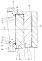
- FIG. 9 is a cross-sectional view taken along the line IX-IX in FIG. 8, showing a cross section taken along a plane including the optical axis O and showing a location where the cover glass 3 is positioned radially inward from the outer shape of the optical member 13.
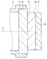
- FIG. 10 is a cross-sectional view taken along the line XX in FIG. 8, which is a cross section taken along a plane including the optical axis O, and shows a portion where the cover glass 3 protrudes radially outward from the outer shape of the optical member 13.
- the out-of-field light reflected toward the display region 2c on the inner wall surface 12c of the protruding portion 12b is the optical member 13. Is blocked by the first light shielding member 4 disposed in front of the first light shielding member 4.
- the out-of-field light incident on the side surface 13 c of the optical member 13 is blocked by the first light blocking member 4 as indicated by two-dot chain lines L ⁇ b> 2 and L ⁇ b> 5. Further, the out-of-field light that is incident on the side surface 13c of the optical member 13 without being blocked by the first light shielding member 4 and is reflected toward the inside of the display region 2c is a second light shielding member disposed behind the optical member 13. Blocked by 5.
- the first light shielding member 4 and the second light shielding member 5 pass out the objective lens unit 10 and reach the rear end of the holding frame 12, such as flare. It can block all harmful light that adversely affects the image.
- the imaging unit 1 and the endoscope 101 of the present embodiment can achieve both downsizing by reducing the diameter of the circular optical member 13 and suppressing flare.
- the protruding portion 12b is provided over the entire circumferential direction of the inner wall surface of the fitting hole 12a so as to form a circular opening for transmitting the light beam emitted from the objective lens unit 10.
- the protruding portion 12b may form an opening having a shape different from a circular shape.
- the opening 12d formed in the fitting hole 12a by the protruding portion 12b is a rectangle or square composed of four sides parallel to the outer shape of the pixel formation region 2b.
- the rectangular or square opening 12d is inscribed in the inner wall surface of the fitting hole 12a. Therefore, the protrusion 12b is divided in the circumferential direction at the four corners of the opening 12d. In other words, when viewed from a direction parallel to the optical axis O, portions overlapping the four corners of the pixel formation region 2b of the protrusion 12b are notched.
- flare caused by out-of-field light reflected by the inner wall surface 12c of the protrusion 12b is generated at the four corners of the pixel formation region 2b at a high image height. Can be prevented.
- the imaging unit 1 of the present embodiment is different from the first embodiment in the location of the first light shielding member 4. As shown in FIG. 12, the first light shielding member 4 of the present embodiment is fixed in contact with the front end surface of the protrusion 12.
- the first light shielding member 4 blocks out-of-field light incident on the inner wall surface 12 c of the protrusion 12. be able to.
- the first light blocking member 4 blocks a part of the out-of-field light incident on the side surface 13c of the optical member 13 as in the first embodiment.
- the second light shielding member 5 since the arrangement location of the second light shielding member 5 is the same as that of the first embodiment, the second light shielding member 5 is incident on the side surface 13c of the optical member 13 without being blocked by the first light shielding member 4. Then, the out-of-view light reflected toward the display area 2c is blocked. Further, the out-of-field light incident on the side surface 3a of the cover glass 3 does not enter the display region 2c.
- the first light shielding member 4 and the second light shielding member 5 convert an image such as flare out of the out-of-field light that passes through the objective lens unit 10 and reaches the rear end of the holding frame 12. Can block all harmful light that causes adverse effects.
- the imaging unit 1 and the endoscope 101 of the present embodiment can achieve both miniaturization by reducing the diameter of the circular optical member 13 and suppression of flare.
Abstract
Priority Applications (4)
| Application Number | Priority Date | Filing Date | Title |
|---|---|---|---|
| EP15796750.6A EP3061384B8 (fr) | 2014-05-21 | 2015-04-15 | Unité de capture d'image et endoscope |
| CN201580002657.4A CN105744877B (zh) | 2014-05-21 | 2015-04-15 | 摄像单元和内窥镜 |
| JP2015550107A JP5897235B1 (ja) | 2014-05-21 | 2015-04-15 | 撮像ユニット及び内視鏡 |
| US15/158,752 US10067333B2 (en) | 2014-05-21 | 2016-05-19 | Endoscope having image pickup sensor and first and second light blocking members |
Applications Claiming Priority (2)
| Application Number | Priority Date | Filing Date | Title |
|---|---|---|---|
| JP2014105495 | 2014-05-21 | ||
| JP2014-105495 | 2014-05-21 |
Related Child Applications (1)
| Application Number | Title | Priority Date | Filing Date |
|---|---|---|---|
| US15/158,752 Continuation US10067333B2 (en) | 2014-05-21 | 2016-05-19 | Endoscope having image pickup sensor and first and second light blocking members |
Publications (1)
| Publication Number | Publication Date |
|---|---|
| WO2015178134A1 true WO2015178134A1 (fr) | 2015-11-26 |
Family
ID=54553810
Family Applications (1)
| Application Number | Title | Priority Date | Filing Date |
|---|---|---|---|
| PCT/JP2015/061636 WO2015178134A1 (fr) | 2014-05-21 | 2015-04-15 | Unité de capture d'image et endoscope |
Country Status (5)
| Country | Link |
|---|---|
| US (1) | US10067333B2 (fr) |
| EP (1) | EP3061384B8 (fr) |
| JP (1) | JP5897235B1 (fr) |
| CN (1) | CN105744877B (fr) |
| WO (1) | WO2015178134A1 (fr) |
Cited By (2)
| Publication number | Priority date | Publication date | Assignee | Title |
|---|---|---|---|---|
| JP2018146878A (ja) * | 2017-03-08 | 2018-09-20 | カンタツ株式会社 | レンズ素子および撮像レンズユニット |
| US11179025B2 (en) * | 2017-05-18 | 2021-11-23 | Olympus Corporation | Image pickup apparatus and endoscope |
Families Citing this family (8)
| Publication number | Priority date | Publication date | Assignee | Title |
|---|---|---|---|---|
| US11782256B2 (en) * | 2016-09-21 | 2023-10-10 | Omnivision Technologies, Inc. | Endoscope imager and associated method |
| JP7088730B2 (ja) * | 2018-04-25 | 2022-06-21 | オリンパス株式会社 | 内視鏡装置 |
| US11690497B2 (en) * | 2018-11-27 | 2023-07-04 | Fujikura Ltd. | Lens unit |
| JP7078560B2 (ja) * | 2019-01-25 | 2022-05-31 | ファナック株式会社 | 精密工作機械 |
| TWI737978B (zh) * | 2019-03-29 | 2021-09-01 | 大立光電股份有限公司 | 成像鏡頭模組及電子裝置 |
| WO2021015133A1 (fr) * | 2019-07-19 | 2021-01-28 | 凸版印刷株式会社 | Élément de protection contre la lumière, unité de lentilles, module de caméra et dispositif électronique |
| CN113288012A (zh) * | 2021-04-30 | 2021-08-24 | 上海澳华内镜股份有限公司 | 一种内窥镜摄像装置 |
| EP4149103A1 (fr) * | 2021-09-08 | 2023-03-15 | Robert Bosch GmbH | Appareil d'imagerie à montage athermique |
Citations (3)
| Publication number | Priority date | Publication date | Assignee | Title |
|---|---|---|---|---|
| JP2005070366A (ja) * | 2003-08-22 | 2005-03-17 | Olympus Corp | 撮像装置 |
| JP2007252943A (ja) * | 2007-05-21 | 2007-10-04 | Olympus Corp | 内視鏡用撮像装置 |
| JP2014036799A (ja) * | 2012-08-20 | 2014-02-27 | Olympus Medical Systems Corp | 光学ユニット及び内視鏡 |
Family Cites Families (17)
| Publication number | Priority date | Publication date | Assignee | Title |
|---|---|---|---|---|
| JP3017245B2 (ja) * | 1989-09-22 | 2000-03-06 | オリンパス光学工業株式会社 | 内視鏡 |
| JP3698839B2 (ja) | 1996-11-18 | 2005-09-21 | オリンパス株式会社 | 内視鏡装置 |
| CN100381853C (zh) * | 1997-08-01 | 2008-04-16 | 奥林巴斯株式会社 | 内窥镜的物镜系统 |
| JP4578913B2 (ja) * | 2004-09-28 | 2010-11-10 | オリンパス株式会社 | 撮像装置 |
| JP5019830B2 (ja) * | 2006-09-20 | 2012-09-05 | オリンパスメディカルシステムズ株式会社 | 撮像ユニット及びこれを適用する内視鏡 |
| JP2008219854A (ja) * | 2007-02-05 | 2008-09-18 | Matsushita Electric Ind Co Ltd | 光学デバイス,光学デバイスウエハおよびそれらの製造方法、ならびに光学デバイスを搭載したカメラモジュールおよび内視鏡モジュール |
| JP5380690B2 (ja) * | 2008-01-08 | 2014-01-08 | オリンパスメディカルシステムズ株式会社 | 内視鏡対物光学系及びそれを用いた内視鏡システム |
| JP5154981B2 (ja) * | 2008-03-10 | 2013-02-27 | オリンパスイメージング株式会社 | ズームレンズを備えた撮像装置 |
| JP2009244529A (ja) * | 2008-03-31 | 2009-10-22 | Konica Minolta Opto Inc | 遮光部及びレンズ鏡胴 |
| JP5289870B2 (ja) * | 2008-09-08 | 2013-09-11 | オリンパスメディカルシステムズ株式会社 | 内視鏡用撮像ユニット |
| JP5779314B2 (ja) * | 2009-08-20 | 2015-09-16 | Hoya株式会社 | 内視鏡装置 |
| WO2011024573A1 (fr) * | 2009-08-31 | 2011-03-03 | オリンパスメディカルシステムズ株式会社 | Dispositif d'imagerie |
| JP5155494B2 (ja) * | 2010-11-09 | 2013-03-06 | オリンパスメディカルシステムズ株式会社 | 内視鏡用撮像装置 |
| WO2012086263A1 (fr) * | 2010-12-22 | 2012-06-28 | コニカミノルタオプト株式会社 | Objectif de prise d'images |
| JP2013174670A (ja) * | 2012-02-23 | 2013-09-05 | Olympus Corp | レンズユニット |
| JP5450704B2 (ja) * | 2012-03-26 | 2014-03-26 | 株式会社フジクラ | 電気ケーブルおよび外筒付き撮像機構、内視鏡、電気ケーブルおよび外筒付き撮像機構の製造方法 |
| JP5425353B1 (ja) * | 2012-04-25 | 2014-02-26 | オリンパスメディカルシステムズ株式会社 | 内視鏡用撮像ユニット及び内視鏡 |
-
2015
- 2015-04-15 WO PCT/JP2015/061636 patent/WO2015178134A1/fr active Application Filing
- 2015-04-15 CN CN201580002657.4A patent/CN105744877B/zh active Active
- 2015-04-15 JP JP2015550107A patent/JP5897235B1/ja active Active
- 2015-04-15 EP EP15796750.6A patent/EP3061384B8/fr not_active Not-in-force
-
2016
- 2016-05-19 US US15/158,752 patent/US10067333B2/en active Active
Patent Citations (3)
| Publication number | Priority date | Publication date | Assignee | Title |
|---|---|---|---|---|
| JP2005070366A (ja) * | 2003-08-22 | 2005-03-17 | Olympus Corp | 撮像装置 |
| JP2007252943A (ja) * | 2007-05-21 | 2007-10-04 | Olympus Corp | 内視鏡用撮像装置 |
| JP2014036799A (ja) * | 2012-08-20 | 2014-02-27 | Olympus Medical Systems Corp | 光学ユニット及び内視鏡 |
Non-Patent Citations (1)
| Title |
|---|
| See also references of EP3061384A4 * |
Cited By (2)
| Publication number | Priority date | Publication date | Assignee | Title |
|---|---|---|---|---|
| JP2018146878A (ja) * | 2017-03-08 | 2018-09-20 | カンタツ株式会社 | レンズ素子および撮像レンズユニット |
| US11179025B2 (en) * | 2017-05-18 | 2021-11-23 | Olympus Corporation | Image pickup apparatus and endoscope |
Also Published As
| Publication number | Publication date |
|---|---|
| US20160266373A1 (en) | 2016-09-15 |
| JPWO2015178134A1 (ja) | 2017-04-20 |
| JP5897235B1 (ja) | 2016-03-30 |
| US10067333B2 (en) | 2018-09-04 |
| EP3061384B1 (fr) | 2018-06-27 |
| CN105744877A (zh) | 2016-07-06 |
| EP3061384A1 (fr) | 2016-08-31 |
| CN105744877B (zh) | 2017-11-21 |
| EP3061384B8 (fr) | 2018-08-08 |
| EP3061384A4 (fr) | 2017-09-06 |
Similar Documents
| Publication | Publication Date | Title |
|---|---|---|
| JP5897235B1 (ja) | 撮像ユニット及び内視鏡 | |
| US6483535B1 (en) | Wide angle lens system for electronic imagers having long exit pupil distances | |
| JP4659848B2 (ja) | 撮像モジュール | |
| JP5080695B2 (ja) | 内視鏡用撮像ユニット | |
| WO2012169369A1 (fr) | Unité optique et endoscope | |
| JP5425353B1 (ja) | 内視鏡用撮像ユニット及び内視鏡 | |
| US10598918B2 (en) | Endoscope lens arrangement for chief ray angle control at sensor | |
| US11042021B2 (en) | Image pickup apparatus and endoscope apparatus | |
| WO2009150653A1 (fr) | Système optique pour endoscope | |
| US10542874B2 (en) | Imaging device and endoscope device | |
| JP2009207578A (ja) | 撮像装置 | |
| JP5841699B2 (ja) | 内視鏡 | |
| JP6415129B2 (ja) | 撮像装置 | |
| TWI581052B (zh) | 廣角取像裝置 | |
| JPWO2018079070A1 (ja) | 内視鏡 | |
| JP2009282423A (ja) | 組レンズ、レンズユニット、撮像装置、および、光学機器 | |
| US20210085157A1 (en) | Endoscope | |
| JP6617206B2 (ja) | 内視鏡 | |
| JP2019028366A (ja) | 撮像光学系及び内視鏡 | |
| JPH0461841A (ja) | 電子内視鏡装置 | |
| JP2012179306A (ja) | 撮像ユニット及び内視鏡 | |
| JP2009109753A (ja) | 撮像装置 |
Legal Events
| Date | Code | Title | Description |
|---|---|---|---|
| ENP | Entry into the national phase |
Ref document number: 2015550107 Country of ref document: JP Kind code of ref document: A |
|
| 121 | Ep: the epo has been informed by wipo that ep was designated in this application |
Ref document number: 15796750 Country of ref document: EP Kind code of ref document: A1 |
|
| REEP | Request for entry into the european phase |
Ref document number: 2015796750 Country of ref document: EP |
|
| WWE | Wipo information: entry into national phase |
Ref document number: 2015796750 Country of ref document: EP |
|
| NENP | Non-entry into the national phase |
Ref country code: DE |