以下に、本発明の好ましい形態について図面を参照して説明する。なお、以下の説明に用いる各図においては、各構成要素を図面上で認識可能な程度の大きさとするため、構成要素毎に縮尺を異ならせてあるものであり、本発明は、これらの図に記載された構成要素の数量、構成要素の形状、構成要素の大きさの比率、及び各構成要素の相対的な位置関係のみに限定されるものではない。
Hereinafter, preferred embodiments of the present invention will be described with reference to the drawings. In the drawings used for the following description, the scale of each component is made different in order to make each component recognizable on the drawing. It is not limited only to the quantity of the component described in (1), the shape of the component, the ratio of the size of the component, and the relative positional relationship of each component.
(第1の実施形態)
以下に、本発明の実施形態の一例を説明する。まず、図1を参照して、本発明に係る内視鏡101の構成の一例を説明する。本実施形態の内視鏡101は、人体等の被検体内に導入可能であって被検体内の所定の観察部位を光学的に撮像可能な構成を有する。なお、内視鏡101が導入される被検体は、人体に限らず、他の生体であってもよいし、機械や建造物等の人工物であってもよい。
(First embodiment)
Hereinafter, an example of an embodiment of the present invention will be described. First, an example of a configuration of an endoscope 101 according to the present invention will be described with reference to FIG. The endoscope 101 of the present embodiment has a configuration that can be introduced into a subject such as a human body and can optically image a predetermined observation site in the subject. The subject into which the endoscope 101 is introduced is not limited to a human body, and may be another living body or an artificial object such as a machine or a building.
本実施形態の内視鏡101は、被検体の内部に導入される細長の挿入部102と、この挿入部102の基端に位置する操作部103と、この操作部103の側部から延出するユニバーサルコード104とで主に構成されている。
The endoscope 101 of the present embodiment includes an elongated insertion portion 102 introduced into the subject, an operation portion 103 located at the proximal end of the insertion portion 102, and a side portion of the operation portion 103. The universal code 104 is mainly configured.
挿入部102は、先端に配設される先端部110、先端部110の基端側に配設される湾曲自在な湾曲部109、及び湾曲部109の基端側に配設され操作部103の先端側に接続される可撓性を有する可撓管部108が連設されて構成されている。先端部110には、対物レンズユニット10及び撮像素子2を含む撮像ユニット1が配設されている。先端部110には、図示しないが、撮像ユニット1の被写体を照明する光を出射する照明光出射部も設けられている。なお、内視鏡101は、挿入部に可撓性を有する部位を具備しない、いわゆる硬性鏡と称される形態のものであってもよい。
The insertion portion 102 is provided at the distal end portion 110 disposed at the distal end, the bendable bending portion 109 disposed on the proximal end side of the distal end portion 110, and the proximal end side of the bending portion 109. A flexible tube portion 108 having flexibility and connected to the distal end side is continuously provided. An imaging unit 1 including the objective lens unit 10 and the imaging element 2 is disposed at the distal end portion 110. Although not shown, the distal end portion 110 is also provided with an illumination light emitting portion that emits light that illuminates the subject of the imaging unit 1. Note that the endoscope 101 may have a so-called rigid endoscope that does not include a flexible portion in the insertion portion.
挿入部102の基端に配設された操作部103には、湾曲部109の湾曲を操作するためのアングル操作ノブ106が設けられている。ユニバーサルコード104の基端部には外部装置120に接続可能に構成された内視鏡コネクタ105が設けられている。内視鏡コネクタ105が接続される外部装置120は、カメラコントロールユニット120aを含んでいる。
The operation unit 103 disposed at the proximal end of the insertion unit 102 is provided with an angle operation knob 106 for operating the bending of the bending unit 109. An endoscope connector 105 configured to be connectable to the external device 120 is provided at the base end portion of the universal cord 104. The external device 120 to which the endoscope connector 105 is connected includes a camera control unit 120a.
内視鏡101内には、挿入部102、操作部103及びユニバーサルコード104内に挿通された伝送ケーブル115が配設されている。伝送ケーブル115は、撮像ユニット1とコネクタ部105とを電気的に接続するように構成されている。コネクタ部105が外部装置120に接続されることによって、撮像ユニット1は、伝送ケーブル115を介して外部装置120のカメラコントロールユニット120aに電気的に接続される。この伝送ケーブル115を介して、外部装置120から撮像ユニット1への電力の供給、及び外部装置120と撮像ユニット1との間の信号の授受が行われる。
In the endoscope 101, a transmission cable 115 inserted in the insertion unit 102, the operation unit 103, and the universal cord 104 is disposed. The transmission cable 115 is configured to electrically connect the imaging unit 1 and the connector unit 105. By connecting the connector unit 105 to the external device 120, the imaging unit 1 is electrically connected to the camera control unit 120 a of the external device 120 via the transmission cable 115. Via this transmission cable 115, power is supplied from the external device 120 to the imaging unit 1, and signals are exchanged between the external device 120 and the imaging unit 1.
カメラコントロールユニット120aは、撮像ユニット1から出力された信号に基づく映像を生成し、画像表示部121に出力する構成を有している。すなわち、本実施形態では、撮像ユニット1により撮像された光学像が、映像として画像表示部121に表示される。なお、カメラコントロールユニット120a及び画像表示部121の一部又は全部は、内視鏡101と一体に構成される形態であってもよい。
The camera control unit 120 a has a configuration that generates a video based on the signal output from the imaging unit 1 and outputs the video to the image display unit 121. That is, in the present embodiment, the optical image captured by the imaging unit 1 is displayed on the image display unit 121 as a video. Note that a part or all of the camera control unit 120 a and the image display unit 121 may be configured integrally with the endoscope 101.
次に、撮像ユニット1の詳細な構成について説明する。図2は、撮像ユニット1の断面図である。撮像ユニット1は、対物レンズユニット10及び撮像素子2を有して構成されている。
Next, the detailed configuration of the imaging unit 1 will be described. FIG. 2 is a cross-sectional view of the imaging unit 1. The imaging unit 1 includes an objective lens unit 10 and an imaging element 2.
対物レンズユニット10は、レンズ、フィルタ、絞り等の複数の光学素子を含み、像面に被写体像を結像するように構成されている。本実施形態では一例として、対物レンズユニット10は、直線状の光軸O上に配置された複数のレンズ10aによって構成されている。以下においては、光軸Oに沿って物体側(被写体側)へ向かう方向を前方と称し、その反対の像側に向かう方向を後方と称するものとする。なお、対物レンズユニット10は、鏡やプリズム等の反射面を有する光学素子を含み、反射面において光軸Oが屈曲する形態であってもよい。
The objective lens unit 10 includes a plurality of optical elements such as lenses, filters, and diaphragms, and is configured to form a subject image on an image plane. In the present embodiment, as an example, the objective lens unit 10 is constituted by a plurality of lenses 10 a arranged on a linear optical axis O. In the following, the direction toward the object side (subject side) along the optical axis O is referred to as the front, and the direction toward the opposite image side is referred to as the rear. The objective lens unit 10 may include an optical element having a reflecting surface such as a mirror or a prism, and the optical axis O may be bent on the reflecting surface.
複数のレンズ10aは、円筒状のレンズ鏡筒11内に固定されている。レンズ鏡筒11の後方端部には、保持枠12が固定されている。保持枠12は円筒状の部材である。保持枠12の前方端部は、レンズ鏡筒11の後方端部に嵌合する。保持枠12の後方端部の内部には、円板状の光学部材13が嵌合する。保持枠12及び光学部材13の詳細については後述するものとする。
The plurality of lenses 10 a are fixed in a cylindrical lens barrel 11. A holding frame 12 is fixed to the rear end of the lens barrel 11. The holding frame 12 is a cylindrical member. The front end portion of the holding frame 12 is fitted to the rear end portion of the lens barrel 11. A disc-shaped optical member 13 is fitted inside the rear end of the holding frame 12. Details of the holding frame 12 and the optical member 13 will be described later.
撮像素子2は、例えばCCD、MOSイメージセンサ、CMOSイメージセンサ等である。撮像素子2は、フォトダイオードからなる複数の画素が配列された受光面2aを有する。
The imaging device 2 is, for example, a CCD, a MOS image sensor, a CMOS image sensor, or the like. The imaging device 2 has a light receiving surface 2a on which a plurality of pixels made of photodiodes are arranged.
撮像素子2の受光面2a上には、受光面2aを封止するためのカバーガラス3が貼着されている。カバーガラス3は、リッドガラス等とも称される。カバーガラス3の前方の面は、光学部材13の後方の面と接着剤により接着されている。すなわち、撮像素子2は、カバーガラス3及び光学部材13を介して、保持枠12に固定される。
A cover glass 3 for sealing the light receiving surface 2a is attached on the light receiving surface 2a of the image pickup device 2. The cover glass 3 is also referred to as lid glass or the like. The front surface of the cover glass 3 is bonded to the rear surface of the optical member 13 with an adhesive. That is, the image sensor 2 is fixed to the holding frame 12 via the cover glass 3 and the optical member 13.
図3は、撮像ユニット1の保持枠12の後方端部、光学部材13、カバーガラス3及び撮像素子2の部分を拡大した断面図である。図4は、撮像素子2の受光面2aの正面図である。図5は、図3のV-V断面図である。図6は、図3のVI-VI断面図である。図7は図3のVII-VII断面図である。
FIG. 3 is an enlarged cross-sectional view of the rear end portion of the holding frame 12 of the imaging unit 1, the optical member 13, the cover glass 3, and the imaging element 2. FIG. 4 is a front view of the light receiving surface 2 a of the image sensor 2. 5 is a cross-sectional view taken along the line VV in FIG. 6 is a cross-sectional view taken along the line VI-VI in FIG. 7 is a sectional view taken along line VII-VII in FIG.
図4に示すように、撮像素子2の受光面2aにおいて、全ての画素は、所定の配列で画素形成領域2b内に形成されている。画素形成領域2bは、例えば長方形又は正方形である。
As shown in FIG. 4, on the light receiving surface 2a of the image sensor 2, all the pixels are formed in a pixel formation region 2b in a predetermined arrangement. The pixel formation region 2b is, for example, a rectangle or a square.
本実施形態においては、カメラコントロールユニット120aは、撮像素子2の画素形成領域2bの全ての画素を用いて画像表示部121に表示する映像を生成するのではなく、画素形成領域2b内の一部の領域内の画素を用いて画像表示部121に表示する映像を生成する。ここで、この映像を生成するための信号生成に用いられる画素からなる領域を、表示領域2cと定義する。
In the present embodiment, the camera control unit 120a does not generate an image to be displayed on the image display unit 121 using all the pixels in the pixel formation region 2b of the image sensor 2, but a part of the pixel formation region 2b. A video to be displayed on the image display unit 121 is generated using pixels in the area. Here, an area composed of pixels used for signal generation for generating the video is defined as a display area 2c.
本実施形態では一例として、表示領域2cは8角形である。より具体的には、表示領域2cは、長方形又は正方形である画素形成領域2bの外形と平行な4つの外辺を有する。表示領域2cは、この4つの外辺からなる四辺形状の4つ角部を直線により切り落とした形状である。撮像素子2は、表示領域2cの中心が、光軸O上に位置するように配設される。また、本実施形態では、画素形成領域2bの中心と表示領域2cの中心とは一致している。
In the present embodiment, as an example, the display area 2c is an octagon. More specifically, the display area 2c has four outer sides parallel to the outer shape of the pixel forming area 2b that is rectangular or square. The display area 2c has a shape in which the four corners of the four-sided shape composed of the four outer sides are cut off by straight lines. The image sensor 2 is disposed so that the center of the display area 2c is positioned on the optical axis O. In the present embodiment, the center of the pixel formation region 2b and the center of the display region 2c coincide.
なお、表示領域2c内に結像された光学像を、画像表示部121に表示する映像に変換するにあたっては、撮像素子2が前記表示領域2c内に位置する画素からの信号のみを出力するように撮像素子2の駆動モードを設定する形態が用いられてもよいし、撮像素子2の全ての画素から出力された信号を読み出した後に、表示領域2c内に相当する領域の映像を画像処理で切り出す形態が用いられてもよい。また、画素形成領域2bの中心と表示領域2cの中心とは一致していなくともよい。また、画素形成領域2bのアスペクト比と表示領域2cのアスペクト比は同一でなくともよい。
When the optical image formed in the display area 2c is converted into an image displayed on the image display unit 121, the image sensor 2 outputs only signals from pixels located in the display area 2c. A mode in which the drive mode of the image sensor 2 is set may be used, or after reading signals output from all the pixels of the image sensor 2, an image of an area corresponding to the display area 2 c is obtained by image processing. The form to cut out may be used. Further, the center of the pixel formation region 2b and the center of the display region 2c do not have to coincide with each other. Further, the aspect ratio of the pixel formation region 2b and the aspect ratio of the display region 2c may not be the same.
図3及び図7に示すように、撮像素子2の受光面2a上には、カバーガラス3が固定されている。カバーガラス3は、画素形成領域2bを封止する部材である。カバーガラス3は、光軸Oに平行な方向から見た場合に長方形又は正方形となる平板である。カバーガラス3は、光軸Oに平行な方向から見た場合に、画素形成領域2bよりも大きい外形を有する。
3 and 7, a cover glass 3 is fixed on the light receiving surface 2a of the image pickup device 2. The cover glass 3 is a member that seals the pixel formation region 2b. The cover glass 3 is a flat plate that is rectangular or square when viewed from a direction parallel to the optical axis O. The cover glass 3 has an outer shape larger than the pixel formation region 2b when viewed from a direction parallel to the optical axis O.
図7に示すように、カバーガラス3は、4つの外辺が、画素形成領域2bの外形と平行となり、かつ光軸Oに平行な方向から見た場合に画素形成領域2b全体を覆うように配設されている。また、カバーガラス3の中心は、光軸O上に位置する。
As shown in FIG. 7, the cover glass 3 has four outer sides parallel to the outer shape of the pixel formation region 2b and covers the entire pixel formation region 2b when viewed from a direction parallel to the optical axis O. It is arranged. The center of the cover glass 3 is located on the optical axis O.
図3及び図6に示すように、カバーガラス3の撮像素子2とは反対側の面、すなわちカバーガラス3の前方の面上には、光学部材13が固定されている。光学部材13は、ガラス等の透明な材料からなり、光軸Oに平行な方向から見た場合に円形となる平板である。円板状である光学部材13は、中心が光軸O上に位置するように配設されている。
As shown in FIGS. 3 and 6, the optical member 13 is fixed on the surface of the cover glass 3 opposite to the imaging device 2, that is, on the front surface of the cover glass 3. The optical member 13 is a flat plate made of a transparent material such as glass and having a circular shape when viewed from a direction parallel to the optical axis O. The optical member 13 having a disc shape is arranged so that the center is located on the optical axis O.
図6に示すように、光学部材13の直径Dは、長方形又は正方形であるカバーガラス3の対角線長Lよりも小さい。また、光学部材13の直径Dは、光軸Oに平行な方向から見た場合に、表示領域2c全体が光学部材13によって覆われる値とされている。このように、円形である光学部材13の直径Dを、長方形又は正方形であるカバーガラス3の対角線長Lよりも小さくすることによって、光学部材13のカバーガラス3の外形からの突出を小さくすることができ、撮像ユニット1の小型化を実現できる。
As shown in FIG. 6, the diameter D of the optical member 13 is smaller than the diagonal length L of the cover glass 3 that is rectangular or square. In addition, the diameter D of the optical member 13 is a value that covers the entire display region 2c when viewed from a direction parallel to the optical axis O. Thus, the protrusion from the external shape of the cover glass 3 of the optical member 13 is made small by making the diameter D of the optical member 13 that is circular smaller than the diagonal length L of the cover glass 3 that is rectangular or square. The imaging unit 1 can be downsized.
図3及び図5に示すように、保持枠12の後方端部には、嵌合孔12aが形成されている。円筒状である保持枠12の後方の端は、光軸Oに対して直交する平面によって切り落とされた形状を有する。
As shown in FIGS. 3 and 5, a fitting hole 12 a is formed at the rear end of the holding frame 12. The rear end of the cylindrical holding frame 12 has a shape cut off by a plane perpendicular to the optical axis O.
嵌合孔12aは、光軸Oを中心とした円形の孔である。嵌合孔12aは、円板状の光学部材13が嵌合する内径を有する。光学部材13は、嵌合孔12a内に後方から前方に向かって挿入され、接着剤により固定される。
The fitting hole 12a is a circular hole centered on the optical axis O. The fitting hole 12a has an inner diameter into which the disc-shaped optical member 13 is fitted. The optical member 13 is inserted into the fitting hole 12a from the rear to the front, and is fixed by an adhesive.
嵌合孔12aの内壁面には、嵌合孔12aの径方向内側に向かって突出する突出部12bが設けられている。突出部12bは、光学部材13の光軸Oに平行な方向の位置決めをするための部位である。本実施形態では、図5に示すように、突出部12bは、嵌合孔12aの内壁面の周方向全体にわたって設けられている。
The inner wall surface of the fitting hole 12a is provided with a protruding portion 12b that protrudes inward in the radial direction of the fitting hole 12a. The protruding portion 12b is a portion for positioning the optical member 13 in a direction parallel to the optical axis O. In this embodiment, as shown in FIG. 5, the protrusion 12b is provided over the entire circumferential direction of the inner wall surface of the fitting hole 12a.
突出部12bは、保持枠12の後方の端から、光軸Oと平行に前方に向かって所定の距離に設けられている。保持枠12の後方の端と、突出部12bの後方の端との間の距離は、光学部材13の厚さよりも短い。
The protrusion 12b is provided at a predetermined distance from the rear end of the holding frame 12 in parallel to the optical axis O toward the front. The distance between the rear end of the holding frame 12 and the rear end of the protruding portion 12 b is shorter than the thickness of the optical member 13.
本実施形態の撮像ユニット1では、図3に示すように、光学部材13の前端面13a及び光学部材13の後端面13bに接して、第1遮光部材4及び第2遮光部材5が配設されている。
In the imaging unit 1 of the present embodiment, as shown in FIG. 3, the first light shielding member 4 and the second light shielding member 5 are disposed in contact with the front end surface 13 a of the optical member 13 and the rear end surface 13 b of the optical member 13. ing.
第1遮光部材4及び第2遮光部材5は、撮像ユニット1の視野外から対物レンズユニット10に入射する視野外光を遮るための部材である。ここで、視野外光とは、対物レンズユニット10を通り保持枠12の後方端部に到達する光線のうち、表示領域2cに像を結ぶ光線以外の光線のことである。第1遮光部材4及び第2遮光部材5は、金属や樹脂等の光を透過しない材料からなる薄板状又は薄膜状の部材である。
The first light-shielding member 4 and the second light-shielding member 5 are members for shielding out-of-field light that enters the objective lens unit 10 from outside the field of the imaging unit 1. Here, the out-of-field light is a light beam other than a light beam that passes through the objective lens unit 10 and reaches the rear end of the holding frame 12 and that forms an image in the display region 2c. The first light shielding member 4 and the second light shielding member 5 are thin plate or thin film members made of a material that does not transmit light such as metal or resin.
第1遮光部材4は、本実施形態では一例として、嵌合孔12aにおいて、突出部12bの後方の端と光学部材13の前端面13aとの間に挟持される薄板状の部材である。なお、第1遮光部材4は、光学部材13の前端面13aに蒸着等により形成される薄膜であってもよい。
The first light shielding member 4 is a thin plate-like member sandwiched between the rear end of the protruding portion 12b and the front end surface 13a of the optical member 13 in the fitting hole 12a as an example in the present embodiment. The first light shielding member 4 may be a thin film formed on the front end surface 13a of the optical member 13 by vapor deposition or the like.
図5に示すように、第1遮光部材4は、光軸Oが貫通する孔である開口部4aを有する。開口部4aは、光軸Oに平行な方向から見た場合に表示領域2cと相似形の8角形であり、各辺が表示領域2cの各辺と平行となるように設けられている。図5においては、表示領域2cの外形を二点鎖線で示している。対物レンズユニット10を通り表示領域2cに像を結ぶ光線は、開口部4a内を通過する。
As shown in FIG. 5, the first light blocking member 4 has an opening 4 a that is a hole through which the optical axis O passes. The opening 4a is an octagon similar to the display region 2c when viewed from a direction parallel to the optical axis O, and is provided so that each side is parallel to each side of the display region 2c. In FIG. 5, the outer shape of the display area 2c is indicated by a two-dot chain line. A light beam that passes through the objective lens unit 10 and forms an image on the display area 2c passes through the opening 4a.
なお、表示領域2cと開口部4aの大きさの関係は、対物レンズユニット10を通り表示領域2cに像を結ぶ光線の角度に応じて適宜に定められる。したがって、図示する本実施形態では、開口部4aは表示領域2cよりも大きいが、開口部4aは、表示領域2cと同一の大きさであってもよいし、表示領域2cよりも小さくてもよい。
The relationship between the size of the display area 2c and the opening 4a is determined as appropriate according to the angle of the light beam that passes through the objective lens unit 10 and forms an image on the display area 2c. Therefore, in the illustrated embodiment, the opening 4a is larger than the display area 2c, but the opening 4a may be the same size as the display area 2c or smaller than the display area 2c. .
第2遮光部材5は、本実施形態では一例として、光学部材13の後端面13b上に形成された金属製の薄膜である。第2遮光部材5は、例えば蒸着法により形成される。なお、第2遮光部材5は、薄板状の部材であってもよい。
The second light shielding member 5 is a metal thin film formed on the rear end surface 13b of the optical member 13 as an example in the present embodiment. The second light shielding member 5 is formed by, for example, a vapor deposition method. The second light shielding member 5 may be a thin plate member.
図6に、光軸Oに平行な方向から見た場合の第2遮光部材5の形状を、網掛けのハッチングで示す。
FIG. 6 shows the shape of the second light shielding member 5 as seen from a direction parallel to the optical axis O by hatching with shading.
図6に示すように、第2遮光部材5は、光学部材13の後端面13bの外縁部であって、対物レンズユニット10を通り表示領域2cに像を結ぶ光線を妨げない領域に設けられている。言い換えれば、第2遮光部材5は、光軸Oが貫通する開口部5aを有する。対物レンズユニット10を通り表示領域2cに像を結ぶ光線は、当該開口部5a内を通過する。
As shown in FIG. 6, the second light shielding member 5 is provided in an outer edge portion of the rear end surface 13 b of the optical member 13 and in an area that does not interfere with a light beam that passes through the objective lens unit 10 and forms an image on the display area 2 c. Yes. In other words, the second light shielding member 5 has an opening 5a through which the optical axis O passes. A light ray that passes through the objective lens unit 10 and forms an image on the display area 2c passes through the opening 5a.
なお、図6においては、表示領域2cの外形を二点鎖線で示している。また、図6において、長方形又は正方形である画素形成領域2bの4つの角部を、一点鎖線で示している。
In FIG. 6, the outer shape of the display area 2c is indicated by a two-dot chain line. In FIG. 6, the four corners of the pixel formation region 2b that is rectangular or square are indicated by alternate long and short dash lines.
第2遮光部材5は、表示領域2cの外辺のうちの、画素形成領域2bの外形と平行な4つの外辺からなる長方形又は正方形と相似形の開口部5aを有する。なお、表示領域2cと開口部5aの大きさの関係は、対物レンズユニット10を通り表示領域2cに像を結ぶ光線の角度に応じて適宜に定められる。したがって、図示する本実施形態では、開口部5aは表示領域2cよりも大きいが、開口部5aは、表示領域2cと同一の大きさであってもよいし、表示領域2cよりも小さくてもよい。
The second light shielding member 5 has an opening 5a similar to a rectangle or square composed of four outer sides parallel to the outer shape of the pixel formation region 2b among the outer sides of the display region 2c. The relationship between the size of the display area 2c and the opening 5a is appropriately determined according to the angle of the light beam that passes through the objective lens unit 10 and forms an image on the display area 2c. Therefore, in the illustrated embodiment, the opening 5a is larger than the display area 2c, but the opening 5a may be the same size as the display area 2c or may be smaller than the display area 2c. .
また、本実施形態では、第2遮光部材5は、図6に示すように、開口部5aの4つの角部に切り欠き部5bを有する。切り欠き部5bは、第2遮光部材5が形成されていない領域であり、光を透過する。切り欠き部5bは、光軸Oに平行な方向から見た場合に、画素形成領域2bの4つの角部に重なる領域に設けられている。
In the present embodiment, as shown in FIG. 6, the second light shielding member 5 has notches 5b at the four corners of the opening 5a. The cutout portion 5b is a region where the second light shielding member 5 is not formed, and transmits light. The notch 5b is provided in a region overlapping the four corners of the pixel formation region 2b when viewed from a direction parallel to the optical axis O.
すなわち、光軸Oに平行に前方から光学部材13、カバーガラス3及び撮像素子2を見た場合に、切り欠き部5bを通して画素形成領域2bの4つの角部が見えるようになる。このように第2遮光部材5の前方から見て画素形成領域2bの4つの角部と重なる領域に切り欠き部5bを設けることにより、第2遮光部材5が形成されている光学部材13の後端面13bと、撮像素子2に固定されたカバーガラス3の前端面とを貼り合わせる場合に、両者を画素形成領域2bの外形を基準として容易に位置決めすることができる。
That is, when the optical member 13, the cover glass 3, and the image sensor 2 are viewed from the front in parallel with the optical axis O, the four corners of the pixel formation region 2b can be seen through the notch 5b. In this way, by providing the notches 5b in the regions overlapping the four corners of the pixel formation region 2b when viewed from the front of the second light shielding member 5, the rear of the optical member 13 on which the second light shielding member 5 is formed. When the end face 13b and the front end face of the cover glass 3 fixed to the image sensor 2 are bonded together, both can be easily positioned based on the outer shape of the pixel formation region 2b.
以上に説明したように、本実施形態の撮像ユニット1は、対物レンズユニット10と、撮像素子2の前端面である受光面2a上に固定された、長方形又は正方形であるカバーガラス3と、カバーガラス3の前端面に貼着された、前記カバーガラス3の対角線長よりも小さい直径の円形の光学部材13と、前記光学部材13が後方から嵌合する円形の嵌合孔12aを有し、前記対物レンズユニット10に対して固定された保持枠12と、前記保持枠12内において、径方向内側に突出する突出部12bと、前記突出部12bと前記光学部材13の前端面13aとの間に配設され、視野外光を遮る第1遮光部材4と、前記光学部材13の後端面13bと前記カバーガラス3との間に配設され、視野外光を遮る第2遮光部材5と、を備える。
As described above, the imaging unit 1 of the present embodiment includes the objective lens unit 10, the rectangular or square cover glass 3 fixed on the light receiving surface 2 a that is the front end surface of the imaging device 2, and the cover. A circular optical member 13 having a diameter smaller than the diagonal length of the cover glass 3 attached to the front end surface of the glass 3, and a circular fitting hole 12a into which the optical member 13 is fitted from behind; A holding frame 12 fixed to the objective lens unit 10, a protruding portion 12 b protruding inward in the radial direction in the holding frame 12, and between the protruding portion 12 b and the front end surface 13 a of the optical member 13. A first light-blocking member 4 that blocks out-of-field light, a second light-blocking member 5 that is disposed between the rear end surface 13b of the optical member 13 and the cover glass 3, and blocks out-of-field light; Is provided.
以下に、第1遮光部材4及び第2遮光部材5の作用を説明する。図8は、光軸Oと平行に前方から見た場合における、保持枠12の後方端部、光学部材13、カバーガラス3及び撮像素子2のそれぞれの外形を示す図である。
Hereinafter, the operation of the first light shielding member 4 and the second light shielding member 5 will be described. FIG. 8 is a diagram illustrating the outer shapes of the rear end portion of the holding frame 12, the optical member 13, the cover glass 3, and the imaging element 2 when viewed from the front in parallel with the optical axis O.
本実施形態の撮像ユニット1では、円形の光学部材13の直径が、長方形又は正方形のカバーガラス3の対角線長よりも小さい。このため、光軸Oと平行に前方から見た場合に、カバーガラス3の4つの角部は、光学部材13の外形よりも径方向外側(光軸Oから遠方)に突出する。その他の箇所では、光軸Oと平行に前方から見た場合に、カバーガラス3の外辺は、光学部材13の外形よりも径方向内側に位置する。
In the imaging unit 1 of the present embodiment, the diameter of the circular optical member 13 is smaller than the diagonal length of the rectangular or square cover glass 3. For this reason, when viewed from the front in parallel with the optical axis O, the four corners of the cover glass 3 protrude radially outward (distant from the optical axis O) from the outer shape of the optical member 13. In other places, when viewed from the front in parallel with the optical axis O, the outer side of the cover glass 3 is located radially inward from the outer shape of the optical member 13.
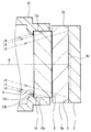
図9は、図8におけるIX-IX断面図であり、光軸Oを含む平面による断面であって、カバーガラス3が光学部材13の外形よりも径方向内側に位置している箇所を示している。図10は、図8におけるX-X断面図であり、光軸Oを含む平面による断面であって、カバーガラス3が光学部材13の外形よりも径方向外側に突出している箇所を示している。
FIG. 9 is a cross-sectional view taken along the line IX-IX in FIG. 8, showing a cross section taken along a plane including the optical axis O and showing a location where the cover glass 3 is positioned radially inward from the outer shape of the optical member 13. Yes. FIG. 10 is a cross-sectional view taken along the line XX in FIG. 8, which is a cross section taken along a plane including the optical axis O, and shows a portion where the cover glass 3 protrudes radially outward from the outer shape of the optical member 13.
撮像ユニット1においてフレア等の像に悪影響をもたらす有害光を遮るには、対物レンズユニット10を通り保持枠12の後方端部に到達する視野外光のうち、突出部12bの内壁面12c、光学部材13の側面13c、及びカバーガラス3の側面3aにおいて反射し、表示領域2cに達する光を遮る必要がある。
In order to block harmful light that adversely affects an image such as flare in the imaging unit 1, out-of-field light that passes through the objective lens unit 10 and reaches the rear end of the holding frame 12, the inner wall surface 12 c of the protruding portion 12 b, optical It is necessary to block light that is reflected on the side surface 13c of the member 13 and the side surface 3a of the cover glass 3 and reaches the display region 2c.
本実施形態では、図9及び図10において二点鎖線の線分L1及びL4として示すように、突出部12bの内壁面12cにおいて表示領域2c内に向かって反射する視野外光は、光学部材13の前方に配設された第1遮光部材4によって遮られる。
In this embodiment, as shown as two-dot chain line segments L1 and L4 in FIGS. 9 and 10, the out-of-field light reflected toward the display region 2c on the inner wall surface 12c of the protruding portion 12b is the optical member 13. Is blocked by the first light shielding member 4 disposed in front of the first light shielding member 4.
図9及び図10において二点鎖線の線分L2及びL5として示すように、光学部材13の側面13cに入射する角度の視野外光の一部は、第1遮光部材4によって遮られる。また、第1遮光部材4によって遮られずに光学部材13の側面13cに入射し、表示領域2c内に向かって反射する視野外光は、光学部材13の後方に配設された第2遮光部材5によって遮られる。
9 and 10, a part of the out-of-field light incident on the side surface 13 c of the optical member 13 is blocked by the first light blocking member 4 as indicated by two-dot chain lines L <b> 2 and L <b> 5. Further, the out-of-field light that is incident on the side surface 13c of the optical member 13 without being blocked by the first light shielding member 4 and is reflected toward the inside of the display region 2c is a second light shielding member disposed behind the optical member 13. Blocked by 5.
図9及び図10において二点鎖線の線分L3及びL6として示すように、カバーガラス3の側面3aに入射する角度の視野外光は、表示領域2cに入射しない。
9 and 10, as shown as two-dot chain line segments L3 and L6, the out-of-field light incident on the side surface 3a of the cover glass 3 does not enter the display region 2c.
以上に説明したように、本実施形態では、第1遮光部材4及び第2遮光部材5によって、対物レンズユニット10を通り保持枠12の後方端部に到達する視野外光のうち、フレア等の像に悪影響をもたらす有害光を全て遮ることができる。
As described above, in the present embodiment, the first light shielding member 4 and the second light shielding member 5 pass out the objective lens unit 10 and reach the rear end of the holding frame 12, such as flare. It can block all harmful light that adversely affects the image.
以上のように、本実施形態の撮像ユニット1及び内視鏡101は、円形の光学部材13の直径を小さくすることによる小型化と、フレアの抑制とを両立することができる。
As described above, the imaging unit 1 and the endoscope 101 of the present embodiment can achieve both downsizing by reducing the diameter of the circular optical member 13 and suppressing flare.
なお、上述した本実施形態では、突出部12bは、対物レンズユニット10から出射された光線を透過させるため円形の開口を形成するように、嵌合孔12aの内壁面の周方向全体にわたって設けられているが、図11に変形例として示すように、突出部12bは、円形とは異なる形状の開口を形成するものであってもよい。
In the above-described embodiment, the protruding portion 12b is provided over the entire circumferential direction of the inner wall surface of the fitting hole 12a so as to form a circular opening for transmitting the light beam emitted from the objective lens unit 10. However, as shown in FIG. 11 as a modified example, the protruding portion 12b may form an opening having a shape different from a circular shape.
図11に示す変形例では、突出部12bによって嵌合孔12a内に形成される開口12dは、画素形成領域2bの外形と平行な4つの辺からなる長方形又は正方形である。長方形又は正方形である開口12dは、嵌合孔12aの内壁面に内接している。したがって、開口12dの4つの角部において突出部12bは周方向に分断されている。言い換えれば、光軸Oに平行な方向から見た場合において、突出部12bの画素形成領域2bの4つの角の近傍に重なる部分は、切り欠かれている。
In the modification shown in FIG. 11, the opening 12d formed in the fitting hole 12a by the protruding portion 12b is a rectangle or square composed of four sides parallel to the outer shape of the pixel formation region 2b. The rectangular or square opening 12d is inscribed in the inner wall surface of the fitting hole 12a. Therefore, the protrusion 12b is divided in the circumferential direction at the four corners of the opening 12d. In other words, when viewed from a direction parallel to the optical axis O, portions overlapping the four corners of the pixel formation region 2b of the protrusion 12b are notched.
このような本変形例であれば、像高の高い位置である画素形成領域2bの4つの角部において、突出部12bの内壁面12cで反射される視野外光を原因とするフレアの発生を防止できる。
In this modification, flare caused by out-of-field light reflected by the inner wall surface 12c of the protrusion 12b is generated at the four corners of the pixel formation region 2b at a high image height. Can be prevented.
(第2の実施形態)
以下に、本発明の第2の実施形態を説明する。以下では第1の実施形態との相違点のみを説明するものとし、第1の実施形態と同様の構成要素については同一の符号を付し、その説明を適宜に省略するものとする。
(Second Embodiment)
The second embodiment of the present invention will be described below. Hereinafter, only differences from the first embodiment will be described, and the same components as those in the first embodiment are denoted by the same reference numerals, and description thereof will be omitted as appropriate.
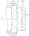
本実施形態の撮像ユニット1は、第1遮光部材4の配置箇所が第1の実施形態と異なる。図12に示すように、本実施形態の第1遮光部材4は、突起部12の前端面に当接して固定されている。
The imaging unit 1 of the present embodiment is different from the first embodiment in the location of the first light shielding member 4. As shown in FIG. 12, the first light shielding member 4 of the present embodiment is fixed in contact with the front end surface of the protrusion 12.
本実施形態のように、突起部12の前端面に第1遮光部材4を配設することにより、突起部12の内壁面12cに入射する角度の視野外光を、第1遮光部材4により遮ることができる。
As in the present embodiment, by arranging the first light shielding member 4 on the front end surface of the protrusion 12, the first light shielding member 4 blocks out-of-field light incident on the inner wall surface 12 c of the protrusion 12. be able to.
また、第1遮光部材4が、光学部材13の側面13cに入射する角度の視野外光の一部を遮ることは、第1の実施形態と同様である。また、第2の遮光部材5の配置箇所は第1の実施形態と同様であるため、第2の遮光部材5は、第1遮光部材4によって遮られずに光学部材13の側面13cに入射し、表示領域2c内に向かって反射する視野外光を遮る。また、カバーガラス3の側面3aに入射する角度の視野外光は表示領域2cに入射しない。
Also, the first light blocking member 4 blocks a part of the out-of-field light incident on the side surface 13c of the optical member 13 as in the first embodiment. In addition, since the arrangement location of the second light shielding member 5 is the same as that of the first embodiment, the second light shielding member 5 is incident on the side surface 13c of the optical member 13 without being blocked by the first light shielding member 4. Then, the out-of-view light reflected toward the display area 2c is blocked. Further, the out-of-field light incident on the side surface 3a of the cover glass 3 does not enter the display region 2c.
以上のように本実施形態においても、第1遮光部材4及び第2遮光部材5によって、対物レンズユニット10を通り保持枠12の後方端部に到達する視野外光のうち、フレア等の像に悪影響をもたらす有害光を全て遮ることができる。
As described above, also in the present embodiment, the first light shielding member 4 and the second light shielding member 5 convert an image such as flare out of the out-of-field light that passes through the objective lens unit 10 and reaches the rear end of the holding frame 12. Can block all harmful light that causes adverse effects.
よって、本実施形態の撮像ユニット1及び内視鏡101は、円形の光学部材13の直径を小さくすることによる小型化と、フレアの抑制とを両立することができる。
Therefore, the imaging unit 1 and the endoscope 101 of the present embodiment can achieve both miniaturization by reducing the diameter of the circular optical member 13 and suppression of flare.
本発明は、上述した実施形態に限られるものではなく、請求の範囲及び明細書全体から読み取れる発明の要旨或いは思想に反しない範囲で適宜変更可能であり、そのような変更を伴う撮像ユニット及び内視鏡もまた本発明の技術的範囲に含まれるものである。
The present invention is not limited to the above-described embodiments, and can be appropriately changed without departing from the spirit or concept of the invention that can be read from the claims and the entire specification. A scope is also included in the technical scope of the present invention.
本出願は、2014年5月21日に日本国に出願された特願2014-105495号を優先権主張の基礎として出願するものであり、上記の開示内容は、本願明細書、請求の範囲、図面に引用されたものとする。
This application is filed on the basis of the priority claim of Japanese Patent Application No. 2014-105495 filed in Japan on May 21, 2014, and the above disclosure is disclosed in the present specification, claims, It shall be cited in the drawing.