JP5154981B2 - Image pickup apparatus having a zoom lens - Google Patents
Image pickup apparatus having a zoom lens Download PDFInfo
- Publication number
- JP5154981B2 JP5154981B2 JP2008059910A JP2008059910A JP5154981B2 JP 5154981 B2 JP5154981 B2 JP 5154981B2 JP 2008059910 A JP2008059910 A JP 2008059910A JP 2008059910 A JP2008059910 A JP 2008059910A JP 5154981 B2 JP5154981 B2 JP 5154981B2
- Authority
- JP
- Japan
- Prior art keywords
- opening
- lens
- imaging
- effective
- flare stop
- Prior art date
- Legal status (The legal status is an assumption and is not a legal conclusion. Google has not performed a legal analysis and makes no representation as to the accuracy of the status listed.)
- Active
Links
Images


Classifications
-
- G—PHYSICS
- G02—OPTICS
- G02B—OPTICAL ELEMENTS, SYSTEMS OR APPARATUS
- G02B15/00—Optical objectives with means for varying the magnification
- G02B15/14—Optical objectives with means for varying the magnification by axial movement of one or more lenses or groups of lenses relative to the image plane for continuously varying the equivalent focal length of the objective
- G02B15/144—Optical objectives with means for varying the magnification by axial movement of one or more lenses or groups of lenses relative to the image plane for continuously varying the equivalent focal length of the objective having four groups only
- G02B15/1441—Optical objectives with means for varying the magnification by axial movement of one or more lenses or groups of lenses relative to the image plane for continuously varying the equivalent focal length of the objective having four groups only the first group being positive
- G02B15/144113—Optical objectives with means for varying the magnification by axial movement of one or more lenses or groups of lenses relative to the image plane for continuously varying the equivalent focal length of the objective having four groups only the first group being positive arranged +-++
Landscapes
- Physics & Mathematics (AREA)
- General Physics & Mathematics (AREA)
- Optics & Photonics (AREA)
- Lenses (AREA)
- Lens Barrels (AREA)
- Studio Devices (AREA)
Description
本発明は、デジタルスチルカメラやデジタルビデオカメラ(以下、総称してデジタルカメラという)に用いられるズームレンズを備えた撮像装置に関するものである。 The present invention relates to an imaging apparatus including a zoom lens used in a digital still camera and a digital video camera (hereinafter collectively referred to as a digital camera).
近年、5〜7倍程度の変倍比を持つズームレンズとCCD( Charge Coupled Device )やCMOS( Complementary Metal-Oxide Semiconductor )のような固体撮像素子とを備えたデジタルカメラが普及してきている。また、最近では、手軽に撮影を楽しみたいというユーザーの要望がますます強くなってきたこともあり、そのようなデジタルカメラであっても、服やカバンのポケット等への収納性が良く持ち運びに便利なように小型化が図られるようになってきている。 In recent years, digital cameras including a zoom lens having a zoom ratio of about 5 to 7 times and a solid-state image sensor such as a charge coupled device (CCD) or a complementary metal-oxide semiconductor (CMOS) have become widespread. Recently, there has been an increasing demand for users to enjoy shooting easily, and even such digital cameras can be easily carried in clothes, bags, etc. For convenience, miniaturization has been achieved.
そのようなズームレンズを備えたデジタルカメラの中には、周知のように、ズームレンズの物体側に、非使用時にレンズを保護するためのバリア機構を備えたものがある。 Some digital cameras equipped with such a zoom lens include a barrier mechanism for protecting the lens when not in use on the object side of the zoom lens, as is well known.
また、そのようなズームレンズを備えたデジタルカメラの中には、フレアやゴーストの原因となる散乱光を遮断するために、ズームレンズ中にフレア絞りを備えているものがある。そのようなフレア絞りを備えたズームレンズとしては、下記の特許文献1〜3に記載されているようなものが知られている。 Some digital cameras equipped with such a zoom lens include a flare stop in the zoom lens in order to block scattered light that causes flare and ghosting. As zoom lenses having such a flare stop, those described in Patent Documents 1 to 3 below are known.
しかし、そのようなデジタルカメラに、従来のものよりも広角であって10倍程度の高変倍比を持つズームレンズを採用すると、最終的に撮像素子に入射する光束である有効光束の、ズームレンズの最も物体側のレンズ面に入射する際の形状と大きさが、従来のズームレンズを使用した場合に比べ、広角端のときと望遠端のときとで顕著に異なるようになる。 However, if a zoom lens having a higher zoom ratio of about 10 times wider than the conventional one is adopted in such a digital camera, the effective light beam that is the light beam finally incident on the image sensor is zoomed. The shape and size of the lens when entering the lens surface closest to the object side are significantly different at the wide-angle end and at the telephoto end than when a conventional zoom lens is used.
そのため、従来のズームレンズを採用する場合よりも、広角・高変倍のズームレンズを採用する場合には、ズームレンズよりも物体側に配置されているバリア機構等の開口部において、フレアやゴーストの原因となる散乱光が発生しやすくなってしまうという問題があった。 Therefore, when using a wide-angle, high-magnification zoom lens, compared to the case of using a conventional zoom lens, flare and ghost are formed at the opening of the barrier mechanism or the like disposed on the object side of the zoom lens. There has been a problem that scattered light that causes the above phenomenon is likely to occur.
また、特許文献1〜3に記載のズームレンズに備えられているフレア絞りは、ズームレンズ内部において発生するフレアやゴーストを除去することを目的としたものであり、ズームレンズよりも物体側に配置されたバリア機構等の開口部によって発生したフレアやゴーストを除去することを考慮して構成されたものではない。そのため、バリア機構等の開口部によって発生したゴーストやフレアを除去するために、特許文献1〜3に記載のズームレンズに備えられているフレア絞りを採用すると、必要以上に有効光束が遮断されてしまい、光量、特に、周辺光量が低下しがちになり、画面周辺部の光量が不足してしまうという問題があった。 Further, the flare stop provided in the zoom lenses described in Patent Documents 1 to 3 is intended to remove flare and ghost generated inside the zoom lens, and is disposed closer to the object side than the zoom lens. It is not configured in consideration of removing flare and ghost generated by the opening of the barrier mechanism or the like. Therefore, if the flare stop provided in the zoom lens described in Patent Documents 1 to 3 is used to remove ghosts and flares generated by the opening of the barrier mechanism or the like, the effective luminous flux is blocked more than necessary. As a result, the amount of light, in particular, the amount of peripheral light tends to decrease, and the amount of light at the periphery of the screen is insufficient.
さらに、特許文献1に記載のズームレンズのようにフレア絞りの開口部の大きさを制御したり、特許文献2に記載のズームレンズのようにフレア絞りを光路から退出自在に設けたり、引用文献3に記載のズームレンズのようにフレア絞りを単体で駆動させたりするものは、いずれも、採用される装置全体を大型化し、かつ、複雑化させてしまうという問題があった。 Further, the size of the opening of the flare stop is controlled as in the zoom lens described in Patent Document 1, the flare stop is provided so as to be retractable from the optical path as in the zoom lens described in Patent Document 2, Each of the zoom lenses described in No. 3 that drives the flare stop alone has a problem that the entire apparatus to be used is enlarged and complicated.
本発明は、このような従来技術の問題点に鑑みてなされたものであり、その目的とするところは、開口部材とフレア絞りとズームレンズを備えていて、広角・高変倍であるにも関わらず、フレアやゴーストが少なく明るい画像が得られる小型の撮像装置を提供することである。 The present invention has been made in view of such problems of the prior art, and the object of the present invention is to provide an aperture member, a flare stop, and a zoom lens. Regardless, it is an object of the present invention to provide a small imaging device that can obtain a bright image with little flare and ghost.
上記の目的を達成するために、本発明に係る撮像装置は、物体側から順に、開口部を有する開口部材と、複数のレンズ群の間隔を適宜変化させることによって変倍を行うズームレンズと、撮像素子とを備える撮像装置において、所定の形状の開口部を有するフレア絞りが、前記複数のレンズ群のうち最も物体側にあるレンズ群と一体的に設けられており、前記開口部材の開口部が、広角端のときには有効光束を遮断せず、かつ、望遠端のときには有効光束の一部を遮断し、前記フレア絞りが、広角端のときには前記開口部材の開口部を通過した有効光束を遮断せず、かつ、望遠端のときには前記開口部材の開口部を通過した有効光束のうち前記開口部材の開口部の淵に当たって散乱した光を遮断することを特徴とする。 In order to achieve the above object, an imaging apparatus according to the present invention includes, in order from the object side, an aperture member having an aperture, a zoom lens that performs zooming by appropriately changing the interval between the plurality of lens groups, and In an imaging device including an imaging device, a flare stop having an opening of a predetermined shape is provided integrally with a lens group closest to the object among the plurality of lens groups, and the opening of the opening member However, the effective beam is not blocked at the wide angle end, and a part of the effective beam is blocked at the telephoto end, and the effective beam that has passed through the opening of the aperture member is blocked at the wide angle end. In addition, at the telephoto end, out of the effective light beam that has passed through the opening of the opening member, light scattered by hitting the eyelid of the opening of the opening member is blocked.
また、本発明に係る撮像装置は、前記開口部材の開口部、前記フレア絞りの開口部及び前記撮像素子の有効撮像領域が、略矩形であり、次の条件式(1)を満たすことが好ましい。
(XA/YA)/(XF/YF) < 1.10 ・・・(1)
ただし、前記撮像素子の有効撮像領域の長手方向をX方向、前記撮像素子の有効撮像領域の長手方向と直交する方向をY方向とし、XAは前記開口部材の有する開口部のX方向の最大値、YAは前記開口部材の有する開口部のY方向の最大値、XFは前記フレア絞りの有する開口部のX方向の最大値、YFは前記フレア絞りの有する開口部のY方向の最大値である。
In the imaging apparatus according to the present invention, it is preferable that the opening of the opening member, the opening of the flare stop, and the effective imaging area of the imaging element are substantially rectangular and satisfy the following conditional expression (1). .
(X A / Y A ) / (X F / Y F ) <1.10 (1)
However, the longitudinal direction of the effective imaging region of the imaging device is the X direction, the direction orthogonal to the longitudinal direction of the effective imaging region of the imaging device is the Y direction, and X A is the maximum in the X direction of the opening of the opening member. Y A is the maximum value in the Y direction of the opening of the aperture member, X F is the maximum value in the X direction of the opening of the flare stop, and Y F is the Y direction of the opening of the flare stop. It is the maximum value.
また、本発明に係る撮像装置は、前記開口部材の開口部、前記フレア絞りの開口部及び前記撮像素子の有効撮像領域が略矩形であり、次の条件式(2)を満足することが好ましい。
(XI/YI)/(XF/YF) < 1.10 ・・・(2)
ただし、前記撮像素子の有効撮像領域の長手方向をX方向、前記撮像素子の有効撮像領域の長手方向と直交する方向をY方向とし、XIは前記撮像素子の有効撮像領域のX方向の最大値、YIは前記撮像素子の有効撮像領域のY方向の最大値、XFは前記フレア絞りの有する開口部のX方向の最大値、YFは前記フレア絞りの有する開口部のY方向の最大値である。
In the image pickup apparatus according to the present invention, it is preferable that the opening of the opening member, the opening of the flare stop, and the effective image pickup area of the image pickup device are substantially rectangular and satisfy the following conditional expression (2). .
(X I / Y I ) / (X F / Y F ) <1.10 (2)
However, the longitudinal direction of the effective imaging region of the imaging device is the X direction, the direction orthogonal to the longitudinal direction of the effective imaging region of the imaging device is the Y direction, and X I is the maximum in the X direction of the effective imaging region of the imaging device. Value, Y I is the maximum value in the Y direction of the effective imaging area of the image sensor, X F is the maximum value in the X direction of the opening of the flare stop, and Y F is the Y direction of the opening of the flare stop. It is the maximum value.
また、本発明に係る撮像装置は、前記ズームレンズが、物体側から順に、正の屈折力を持つ第1レンズ群と、負の屈折力を持つ第2レンズ群と、開口絞りと、正の屈折力を持つ第3レンズ群とを有し、前記撮像素子が固体撮像素子であって、変倍の際に前記フレア絞りと前記第1レンズ群とが一体的に移動し、次の条件式(3)及び(4)を満たすことが好ましい。
0.5 < fw/D < 1 ・・・(3)
4.5 < ft/fw < 50 ・・・(4)
ただし、fwは前記ズームレンズの広角端での焦点距離、ftは前記ズームレンズの望遠端での焦点距離、Dは前記固体撮像素子の対角長である。
In the image pickup apparatus according to the present invention, the zoom lens includes, in order from the object side, a first lens group having a positive refractive power, a second lens group having a negative refractive power, an aperture stop, and a positive aperture. A third lens group having a refractive power, and the imaging device is a solid-state imaging device, and the flare stop and the first lens group move together during zooming, and the following conditional expression: It is preferable to satisfy (3) and (4).
0.5 <fw / D <1 (3)
4.5 <ft / fw <50 (4)
Here, fw is the focal length at the wide-angle end of the zoom lens, ft is the focal length at the telephoto end of the zoom lens, and D is the diagonal length of the solid-state imaging device.
また、本発明に係る撮像装置は、前記開口部材と前記フレア絞りが、望遠端のとき、有効光束の最大像高の主光線を遮断しないことが好ましい。 In the image pickup apparatus according to the present invention, it is preferable that the chief ray having the maximum image height of the effective light beam is not blocked when the aperture member and the flare stop are at the telephoto end.
また、本発明に係る撮像装置は、歪曲収差を画像処理により補正することが好ましい。 In the imaging apparatus according to the present invention, it is preferable to correct distortion by image processing.
本発明によれば、開口部材とフレア絞りとズームレンズを備えていて、広角・高変倍であるにも関わらず、フレアやゴーストが少なく明るい画像が得られる小型の撮像装置を提供することができる。 According to the present invention, it is possible to provide a small-sized imaging device that includes an aperture member, a flare stop, and a zoom lens, and that can obtain a bright image with little flare and ghosting despite having a wide angle and high zoom ratio. it can.
本発明の実施例の説明に先立ち、本発明に係る撮像装置の構成による作用効果を説明する。 Prior to the description of the embodiments of the present invention, the operational effects of the configuration of the imaging apparatus according to the present invention will be described.
本発明に係る撮像装置は、物体側から順に、開口部を有する開口部材と、複数のレンズ群の間隔を適宜変化させることによって変倍を行うズームレンズと、撮像素子とを備える撮像装置を前提としている。 An imaging apparatus according to the present invention is premised on an imaging apparatus that includes an aperture member having an aperture, an zoom member that performs zooming by appropriately changing an interval between a plurality of lens groups, and an imaging element in order from the object side. It is said.
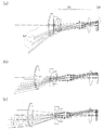
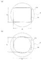
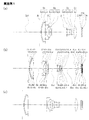
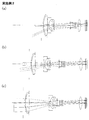
ここで、図1及び図2を用いて、本発明と同様な広角・高変倍が得られるようにした場合における従来の撮像装置のズームレンズに入射する光束について説明する。図1は、広角・高変倍のズームレンズの無限遠物点合焦時の構成を示す光軸に沿う断面図であり、(a)は広角端、(b)は中間、(c)は望遠端における状態をそれぞれ示している。図2は、図1に示したズームレンズにより撮像面上に像を結ぶ有効光束の、ズームレンズの最も物体側レンズ面における断面形状を示す図であり、(a)は広角端、(b)は望遠端における状態をそれぞれ示している。 Here, with reference to FIG. 1 and FIG. 2, a description will be given of a light beam incident on a zoom lens of a conventional imaging device in a case where a wide angle and high zoom ratio similar to those of the present invention are obtained. FIG. 1 is a cross-sectional view along the optical axis showing the configuration of a wide-angle / high-magnification zoom lens when focusing on an object point at infinity, where (a) is the wide-angle end, (b) is the middle, and (c) is Each state at the telephoto end is shown. 2 is a diagram showing a cross-sectional shape of the effective light beam that forms an image on the imaging surface by the zoom lens shown in FIG. 1 on the most object side lens surface of the zoom lens, where (a) is a wide angle end, and (b). Indicates the state at the telephoto end.
図1に示した広角・高変倍のズームレンズZLの像側には、矩形の有効撮像領域を有する撮像面IMを持つ撮像素子が配置されている。この図1に示すように、ズームレンズZLが広角・高変倍である場合、撮像面IM上に像を結ぶ一つ一つの光束LFの径は、広角端のときよりも、望遠端のときのほうがかなり大きい。 On the image side of the wide-angle / high-magnification zoom lens ZL shown in FIG. 1, an imaging element having an imaging surface IM having a rectangular effective imaging area is arranged. As shown in FIG. 1, when the zoom lens ZL has a wide angle and a high zoom ratio, the diameter of each light beam LF that forms an image on the imaging surface IM is larger at the telephoto end than at the wide angle end. Is much bigger.
そのため、ズームレンズZLの最も物体側のレンズの物体側の面に入射する光束のうち、最終的に撮像面IMの有効撮像領域に入射する光束LFにより形成される有効光束の断面形状は、広角端においては、図2(a)に示すような略矩形の形状LFWとなり、望遠端においては、図2(b)に示すような略円形の形状LFTとなる。なお、各有効光束の断面形状において一点鎖線で示した矩形は、有効光束を形成する光束のうち、最も外側の光束の主光線PRを結んだ線である。 Therefore, among the light beams incident on the object-side surface of the lens closest to the object of the zoom lens ZL, the cross-sectional shape of the effective light beam finally formed by the light beam LF incident on the effective imaging region of the imaging surface IM is a wide angle. in the end, a substantially rectangular shape LF W becomes as shown in FIG. 2 (a), in the telephoto end, a substantially circular shape LF T as shown in FIG. 2 (b). In addition, the rectangle shown with the dashed-dotted line in the cross-sectional shape of each effective light beam is a line | wire which connected the chief ray PR of the outermost light beam among the light beams which form an effective light beam.
このように、ズームレンズは、広角・高変倍であればあるほど、広角端における有効光束の形状や大きさと、望遠端における有効光束の形状や大きさとが、著しく異なることになる。そのため、撮像装置に採用されるズームレンズが、広角・高変倍であるとバリア機構やフレア絞りを採用した場合でも、十分に光量を確保しつつフレアやゴーストを除去するとともに、装置全体の小型化を実現することは難しい。 As described above, as the zoom lens has a wide angle and high zoom ratio, the shape and size of the effective light beam at the wide angle end and the shape and size of the effective light beam at the telephoto end are significantly different. Therefore, if the zoom lens used in the imaging device is wide-angle and high-magnification, even when a barrier mechanism or a flare stop is used, the flare and ghost are removed while ensuring a sufficient amount of light, and the overall size of the device is reduced. It is difficult to realize.
このような問題を解決するために、本発明に係る撮像装置は、開口部材の開口部が、広角端のときには有効光束を遮断せず、かつ、望遠端のときに有効光束の一部を遮断し、フレア絞りが、広角端のときには前記開口部材の開口部を通過した有効光束を遮断せず、かつ、望遠端のときには前記開口部材の開口部を通過した有効光束のうち前記開口部材の開口部の淵に当たって散乱した光を遮断するように構成している。 In order to solve such a problem, the imaging apparatus according to the present invention does not block the effective light beam when the aperture of the aperture member is at the wide-angle end, and blocks a part of the effective light beam at the telephoto end. When the flare stop is at the wide-angle end, the effective light beam that has passed through the opening of the opening member is not blocked, and when the flare stop is at the telephoto end, the aperture of the opening member is out of the effective light beam that has passed through the opening of the opening member. It is configured to block the light scattered by hitting the ridge of the part.
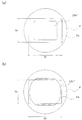
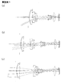
ここで、図3及び図4を用いて、本発明に係る撮像装置の開口部材の開口部とフレア絞りについて説明する。図3は、本発明に係る撮像装置の開口部材と、その開口部材によって遮断される有効光束の領域を示す図であり、(a)は広角端、(b)は望遠端における状態をそれぞれ示している。図4は、本発明に係る撮像装置のフレア絞りと、そのフレア絞りによって遮断される有効光束の領域を示す図であり、(a)は広角端、(b)は望遠端における状態をそれぞれ示している。なお、これらの図において、遮断される有効光束の領域は、ハッチングにより表している。また、符号については、図1図2と同様のものについては、同様の符号を付している。 Here, the opening part and the flare stop of the opening member of the imaging apparatus according to the present invention will be described with reference to FIGS. 3 and 4. 3A and 3B are diagrams showing an aperture member of the imaging apparatus according to the present invention and an effective light beam area blocked by the aperture member, where FIG. 3A shows a state at the wide-angle end, and FIG. 3B shows a state at the telephoto end. ing. 4A and 4B are diagrams showing a flare stop of the imaging apparatus according to the present invention and an effective light beam area blocked by the flare stop. FIG. 4A shows a state at the wide-angle end, and FIG. 4B shows a state at the telephoto end. ing. In these drawings, the area of the effective light beam to be blocked is indicated by hatching. Moreover, about the code | symbol same about FIG. 1 and FIG. 2, the same code | symbol is attached | subjected.
上述したように、広角・高変倍のズームレンズでは、広角端においては入射する光束の径が小さく、望遠端においては入射する光束の径が大きい。そのため、撮像装置にそのようなズームレンズを採用する場合、広角端においては、Fナンバーを小さくしなければ、取得する画像の明るさを十分に確保することができないが、望遠端においては、Fナンバーがある程度大きくても取得する画像の明るさを十分に確保することができる。一方、ズームレンズの物体側に配置されるバリア機構は、デジタルカメラの使用時に羽根を収納するスペースを確保しつつ、小型であることが望ましいため、バリア機構の開口部材に形成される開口部は可能な限り小型であることが望ましい。 As described above, in a zoom lens having a wide angle and a high zoom ratio, the diameter of the incident light beam is small at the wide angle end, and the diameter of the incident light beam is large at the telephoto end. Therefore, when such a zoom lens is employed in the image pickup apparatus, the brightness of an image to be acquired cannot be sufficiently ensured unless the F number is reduced at the wide-angle end, but at the telephoto end, F Even if the number is somewhat large, the brightness of the acquired image can be sufficiently secured. On the other hand, the barrier mechanism disposed on the object side of the zoom lens desirably has a small size while securing a space for storing the blades when the digital camera is used. Therefore, the opening formed in the opening member of the barrier mechanism is It is desirable to be as small as possible.
本発明の開口部材Aの開口部Aaは、図3(a)に示すように、広角端においては、有効光束LFWを全て通過させるため、開口部Aaにおいては、フレアやゴーストの原因となる散乱光は発生せず、また、取得する画像の明るさも十分に確保することができる。 As shown in FIG. 3A , the opening A A of the opening member A of the present invention allows all the effective light beam LF W to pass through at the wide-angle end. Therefore, the opening A a causes flare and ghost. Scattered light is not generated, and the brightness of the acquired image can be sufficiently secured.
一方、図3(b)に示すように、望遠端においては、有効光束LFTの一部を遮断するため、本発明の開口部Aaの淵において、フレアやゴーストの原因となる散乱光が発生してしまうものの、十分な明るさを確保することができ、また、装置全体の小型化も実現することができる。 On the other hand, as shown in FIG. 3 (b), in the telephoto end, for blocking a part of the effective light beam LF T, in edge of the opening A a of the present invention, scattered light which causes flare and ghost Although it occurs, sufficient brightness can be ensured, and downsizing of the entire apparatus can be realized.
また、本発明のフレア絞りFの開口部Faは、図4(a)に示すように、開口部材Aの開口部Aaを通過した有効光束LFW’を全て通過させるため、開口部材Aと同様に、取得する画像の明るさを十分に確保することができる。なお、開口部材Aにおいてフレアやゴーストの原因となる散乱光が発生していないため、開口部材Aの開口部Aaの淵における反射を原因とするフレアやゴーストが発生することもない。 Further, as shown in FIG. 4A , the opening Fa of the flare stop F of the present invention passes through the effective light beam LF W ′ that has passed through the opening Aa of the opening member A. Similarly, the brightness of the acquired image can be sufficiently secured. Since the scattered light which causes flare or ghost in the opening member A does not occur, flares and ghosts is not generated caused by reflection at the edge of the opening A a of the opening member A.
一方、図4(b)に示すように、望遠端において、開口部材Aの開口部Aaで一部が遮断された有効光束LFT’のうち、フレアやゴーストの原因となる散乱光を含む部分をさらに遮断するため、撮像素子において取得される画像には、ゴーストやフレアが発生を抑えることができる。なお、有効光束の一部がさらに遮断されるため、取得される画像の一部においては、周辺光量が低下するが、有効光束を形成する一つ一つの光束の径が大きいため、全体としては十分な明るさを確保することができる。 On the other hand, as shown in FIG. 4B, the effective light beam LF T ′ partially blocked by the opening A a of the aperture member A at the telephoto end includes scattered light that causes flare and ghost. Since the portion is further cut off, it is possible to suppress the occurrence of ghost and flare in the image acquired by the image sensor. In addition, since a part of the effective light beam is further blocked, the peripheral light amount is reduced in a part of the acquired image, but the diameter of each light beam forming the effective light beam is large. Sufficient brightness can be ensured.
従って、本発明に係る撮像装置は、このような特徴的な開口部を有する開口部材とフレア絞りとを併せ持っているため、広角端、望遠他のいずれにおいても、取得する画像の明るさを十分に確保することができるとともに、ゴーストやフレアを除去することができる。 Therefore, since the imaging apparatus according to the present invention has both the aperture member having such a characteristic aperture and the flare stop, the brightness of the image to be acquired is sufficient at both the wide-angle end and the telephoto end. Ghosts and flares can be removed.
また、本発明に係る撮像装置は、フレア絞りFが、開口部材と第2レンズ群との間において、第1レンズ群と一体的に設けられており、その開口部Faが、所定の形状となっていて変形しない構成としている。 The imaging apparatus according to the present invention, flare stop F is, between the opening member and the second lens group is provided integrally with the first lens group, the aperture F a is a predetermined shape The structure is such that it does not deform.
本発明で前提としている撮像装置に採用されるようなズームレンズは、入射した有効光束の形状が、広角端であっても望遠端であっても、撮像素子に近づくにつれ、撮像素子の形状(一般的には略矩形)に近い形状に変化する。そのため、撮像素子に近すぎる位置にフレア絞りを配置すると、望遠端においてのみ有効光束の一部を遮断することが難しくなる。そのため、本発明においては、フレア絞りを、第1レンズ群と一体的に設けている。 The zoom lens as employed in the imaging apparatus premised on the present invention has a shape of the imaging device (as the shape of the imaging device becomes closer to the imaging device, regardless of whether the shape of the incident effective light beam is the wide-angle end or the telephoto end. In general, the shape changes to a shape close to a substantially rectangular shape. Therefore, if a flare stop is disposed at a position too close to the image sensor, it becomes difficult to block a part of the effective light beam only at the telephoto end. Therefore, in the present invention, the flare stop is provided integrally with the first lens group.
また、そのような位置にフレア絞りを配置しているため、フレア絞りの開口部の形状を変化させなくても、望遠端においてのみ、光束の一部を遮断することできる。そのため、フレア絞りの開口部の形状を変化させる機構や、変倍時に独立して移動させるための機構が必要なく、撮像装置全体の小型化も容易に実現できる。 In addition, since the flare stop is disposed at such a position, a part of the light beam can be blocked only at the telephoto end without changing the shape of the opening of the flare stop. For this reason, there is no need for a mechanism for changing the shape of the opening of the flare stop or a mechanism for moving the flare diaphragm independently at the time of zooming, and the entire image pickup apparatus can be easily downsized.
また、本発明に係る撮像装置は、開口部材の開口部、フレア絞りの開口部及び撮像素子の有効撮像領域が略矩形であり、次の条件式(1)を満たすように構成することが好ましい。
(XA/YA)/(XF/YF) < 1.10 ・・・(1)
ただし、撮像素子の有効撮像領域の長手方向をX方向、撮像素子の有効撮像領域の長手方向と直交する方向をY方向とし、XAは開口部材の有する開口部のX方向の最大値、YAは開口部材の有する開口部のY方向の最大値(図3参照)、XFはフレア絞りの有する開口部のX方向の最大値、YFはフレア絞りの有する開口部のY方向の最大値である(図4参照)。
The imaging apparatus according to the present invention is preferably configured so that the aperture of the aperture member, the aperture of the flare stop, and the effective imaging area of the imaging element are substantially rectangular and satisfy the following conditional expression (1). .
(X A / Y A ) / (X F / Y F ) <1.10 (1)
However, the longitudinal direction of the effective imaging region of the imaging device is the X direction, the direction orthogonal to the longitudinal direction of the effective imaging region of the imaging device is the Y direction, X A is the maximum value in the X direction of the opening of the opening member, Y A is the maximum value in the Y direction of the opening of the aperture member (see FIG. 3), X F is the maximum value of the opening of the flare stop in the X direction, and Y F is the maximum of the opening of the flare stop in the Y direction. Value (see FIG. 4).
条件式(1)の上限値を上回ると、開口部材の開口部の淵に有効光束の一部が当たって発生した散乱光が、フレア絞りを通過して撮像素子に到達しやすくなってしまう。また、フレア絞りにおいて遮断される範囲が大きくなりすぎてしまうため、画面対角方向での周辺光量を十分に確保することができなくなってしまう。 If the upper limit value of conditional expression (1) is exceeded, scattered light generated when a part of the effective light beam strikes the edge of the opening of the aperture member will easily pass through the flare stop and reach the image sensor. In addition, since the range to be blocked by the flare stop becomes too large, it becomes impossible to secure a sufficient amount of peripheral light in the diagonal direction of the screen.
なお、条件式(1)に代わり、次の条件式(1)’,(1)”のいずれかを満足するように構成するとさらに好ましい。
0.3 < (XA/YA)/(XF/YF) < 1.05 ・・・(1)’
0.6 < (XA/YA)/(XF/YF) < 1.02 ・・・(1)”
また、条件式(1)’の上限値又は下限値を、条件式(1),(1)”の上限値又は下限値としても良いし、条件式(1)”の上限値又は下限値を、条件式(1),(1)’の上限値又は下限値としても良い。
In addition, it is more preferable to configure so as to satisfy one of the following conditional expressions (1) ′ and (1) ″ instead of conditional expression (1).
0.3 <(X A / Y A ) / (X F / Y F ) <1.05 (1) ′
0.6 <(X A / Y A ) / (X F / Y F ) <1.02 (1) ”
Further, the upper limit value or lower limit value of conditional expression (1) ′ may be used as the upper limit value or lower limit value of conditional expression (1), (1) ″, or the upper limit value or lower limit value of conditional expression (1) ″ may be The upper limit value or lower limit value of conditional expressions (1) and (1) ′ may be used.
また、本発明に係る撮像装置は、開口部材の開口部、フレア絞りの開口部及び撮像素子の有効撮像領域が略矩形であり、次の条件式(2)を満たすように構成することが好ましい。
(XI/YI)/(XF/YF) < 1.10 ・・・(2)
ただし、撮像素子の有効撮像領域の長手方向をX方向、撮像素子の有効撮像領域の長手方向に直交する方向をY方向とし、XIは撮像素子の有効撮像領域のX方向の最大値、YIは撮像素子の有効撮像領域のY方向の最大値、XFはフレア絞りの有する開口部のX方向の最大値、YFはフレア絞りの有する開口部のY方向の最大値である(図4参照)。
In addition, the imaging apparatus according to the present invention is preferably configured so that the aperture of the aperture member, the aperture of the flare stop, and the effective imaging area of the imaging element are substantially rectangular and satisfy the following conditional expression (2). .
(X I / Y I ) / (X F / Y F ) <1.10 (2)
However, the longitudinal direction of the effective imaging area of the image sensor is the X direction, the direction orthogonal to the longitudinal direction of the effective imaging area of the image sensor is the Y direction, and X I is the maximum value in the X direction of the effective imaging area of the image sensor, Y I is the maximum value in the Y direction of the effective imaging area of the image sensor, X F is the maximum value in the X direction of the opening of the flare stop, and Y F is the maximum value in the Y direction of the opening of the flare stop (see FIG. 4).
条件式(2)の上限値を上回ると、開口部材の開口部の淵に有効光束の一部が当たって発生した散乱光が、フレア絞りを通過して撮像素子に到達しやすくなってしまう。また、フレア絞りにおいて遮断される範囲が大きくなりすぎてしまうため、画面周辺部での光量を十分に確保することができなくなってしまう。 If the upper limit value of conditional expression (2) is exceeded, scattered light generated when a part of the effective light beam hits the edge of the aperture of the aperture member will easily pass through the flare stop and reach the image sensor. In addition, since the range that is blocked by the flare stop becomes too large, it becomes impossible to ensure a sufficient amount of light at the periphery of the screen.
なお、条件式(2)に代わり、次の条件式(2)’,(2)”のいずれかを満足するように構成するとさらに好ましい。
0.3 < (XI/YI)/(XF/YF) < 1.05 ・・・(2)’
0.6 < (XI/YI)/(XF/YF) < 1.03 ・・・(2)”
また、条件式(2)’の上限値又は下限値を、条件式(2),(2)”の上限値又は下限値としても良いし、条件式(2)”の上限値又は下限値を、条件式(2),(2)’の上限値又は下限値としても良い。
In addition, it is more preferable to configure so as to satisfy one of the following conditional expressions (2) ′ and (2) ″ instead of conditional expression (2).
0.3 <(X I / Y I ) / (X F / Y F ) <1.05 (2) ′
0.6 <(X I / Y I ) / (X F / Y F ) <1.03 (2) ”
Further, the upper limit value or lower limit value of conditional expression (2) ′ may be used as the upper limit value or lower limit value of conditional expression (2), (2) ″, or the upper limit value or lower limit value of conditional expression (2) ″ may be The upper limit value or lower limit value of conditional expressions (2) and (2) ′ may be used.
また、本発明に係る撮像装置は、ズームレンズが、物体側から順に、正の屈折力を持つ第1レンズ群と、負の屈折力を持つ第2レンズ群と、開口絞りと、正の屈折力を持つ第3レンズ群とを有し、撮像素子が固体撮像素子であって、変倍の際に前記フレア絞りと第1レンズ群とが一体的に移動し、次の条件式(3)及び(4)を満たすように構成することが好ましい。
0.5 < fw/D < 1 ・・・(3)
4.5 < ft/fw < 50 ・・・(4)
ただし、fwはズームレンズの広角端での焦点距離、ftはズームレンズの望遠端での焦点距離、Dは固体撮像素子の対角長である。
In the imaging apparatus according to the present invention, the zoom lens includes, in order from the object side, a first lens group having a positive refractive power, a second lens group having a negative refractive power, an aperture stop, and a positive refraction. And a third lens group having power, and the imaging device is a solid-state imaging device, and the flare stop and the first lens group move integrally during zooming, and the following conditional expression (3) And (4) are preferably satisfied.
0.5 <fw / D <1 (3)
4.5 <ft / fw <50 (4)
Here, fw is the focal length at the wide-angle end of the zoom lens, ft is the focal length at the telephoto end of the zoom lens, and D is the diagonal length of the solid-state imaging device.
条件式(3)の上限値を上回ると、広角・高変倍化が実現しにくい。一方、条件式(3)の下限値を下回ると、開口部材の開口部の淵を通過する光線の高さと第1レンズ群の有効径の差が大きくなりすぎてしまうため、条件式(2)を満たすように構成しても、ズームレンズの径方向の大きさが大きくなってしまい、撮像装置の小型化が困難になってしまう。 If the upper limit value of conditional expression (3) is exceeded, it is difficult to realize wide angle and high zoom ratio. On the other hand, if the lower limit value of conditional expression (3) is not reached, the difference between the height of the light beam passing through the ridge of the aperture of the aperture member and the effective diameter of the first lens group becomes too large, so that conditional expression (2) Even if configured to satisfy the above, the size of the zoom lens in the radial direction becomes large, and it becomes difficult to reduce the size of the imaging apparatus.
なお、条件式(3)に代わり、次の条件式(3)’,(3)”のいずれかを満足するように構成するとさらに好ましい。
0.3 < fw/D < 0.9 ・・・(3)’
0.6 < fw/D < 0.8 ・・・(3)”
また、条件式(3)’の上限値又は下限値を、条件式(3),(3)”の上限値又は下限値としても良いし、条件式(3)”の上限値又は下限値を、条件式(3),(3)’の上限値又は下限値としても良い。
In addition, it is more preferable to configure so as to satisfy one of the following conditional expressions (3) ′ and (3) ″ instead of conditional expression (3).
0.3 <fw / D <0.9 (3) ′
0.6 <fw / D <0.8 (3) "
Further, the upper limit value or lower limit value of conditional expression (3) ′ may be the upper limit value or lower limit value of conditional expression (3), (3) ″, or the upper limit value or lower limit value of conditional expression (3) ″ may be The upper limit value or lower limit value of conditional expressions (3) and (3) ′ may be used.
条件式(4)の上限値を上回ると、ズーム全域に渡って十分な結像性能を確保することが困難となってしまう。一方、条件式(4)の下限値を下回ると、高変倍のズームレンズを設計することができない。 If the upper limit of conditional expression (4) is exceeded, it will be difficult to ensure sufficient imaging performance over the entire zoom range. On the other hand, if the lower limit of conditional expression (4) is not reached, a zoom lens with a high zoom ratio cannot be designed.
なお、条件式(4)に代わり、次の条件式(4)’,(4)”のいずれかを満足するように構成するとさらに好ましい。
5.5 < ft/fw < 30 ・・・(4)’
8.5 < ft/fw < 25 ・・・(4)”
また、条件式(4)’の上限値又は下限値を、条件式(4),(4)”の上限値又は下限値としても良いし、条件式(4)”の上限値又は下限値を、条件式(4),(4)’の上限値又は下限値としても良い。
In addition, it is more preferable to configure so as to satisfy one of the following conditional expressions (4) ′ and (4) ″ instead of conditional expression (4).
5.5 <ft / fw <30 (4) ′
8.5 <ft / fw <25 (4) "
Further, the upper limit value or lower limit value of the conditional expression (4) ′ may be used as the upper limit value or lower limit value of the conditional expression (4), (4) ″, or the upper limit value or lower limit value of the conditional expression (4) ″ may be The upper limit value or lower limit value of conditional expressions (4) and (4) ′ may be used.
また、本発明に係る撮像装置は、開口部材とフレア絞りが、有効光束の最大像高の主光線を遮断しないように構成することが好ましい。 Further, the imaging apparatus according to the present invention is preferably configured such that the aperture member and the flare stop do not block the principal ray having the maximum image height of the effective light beam.
このような構成とする事で、望遠端においても軸外光束の主光線を撮像素子上で検出可能となる。 With such a configuration, the principal ray of the off-axis light beam can be detected on the image sensor even at the telephoto end.
また、本発明に係る撮像装置は、歪曲収差を画像処理により補正するように構成することが好ましい。 In addition, the imaging apparatus according to the present invention is preferably configured to correct distortion by image processing.
広角端においては、歪曲収差は大きくなりやすいため、大きな負の歪曲収差が発生しやすい。そこで、開口部材の開口部を糸巻き型に形成して広角端における有効光束を制限しても良いが、製造が困難となってしまう。そこで、画像処理によって歪曲収差を補正するようにすると、開口部材の開口部の形状を略矩形としても構わなくなるため、開口部材を製造しやすくなる。 At the wide-angle end, distortion tends to be large, and thus large negative distortion is likely to occur. Therefore, the opening of the opening member may be formed in a pincushion type to limit the effective light beam at the wide-angle end, but manufacturing becomes difficult. Therefore, if the distortion is corrected by image processing, the shape of the opening of the opening member may be substantially rectangular, which makes it easier to manufacture the opening member.
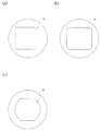
ここで、開口部材やフレア絞りの開口部の形状について説明する。図5は、フレア絞りの構成例を示す図であり、(a)は4隅をカットしていない矩形の開口部aを有するフレア絞りを、(b)は矩形の4隅を丸めて形成した略矩形の開口部aを有するフレア絞りを、(c)は矩形の何れかの対向する二辺を曲線とした略矩形の開口部aを有するフレア絞りを、それぞれ示している。開口部材の開口部やフレア絞りの開口部は、図2や図3において示したような略矩形ではあるが、実際には4隅を小さくカットした八角形の他、図5に示したような形状にしても良い。 Here, the shapes of the opening member and the opening of the flare stop will be described. 5A and 5B are diagrams showing a configuration example of the flare stop, in which FIG. 5A is a flare stop having a rectangular opening a in which the four corners are not cut, and FIG. 5B is formed by rounding the four corners of the rectangle. FIG. 2C shows a flare stop having a substantially rectangular opening a, and FIG. 3C shows a flare stop having a substantially rectangular opening a with two opposing sides of the rectangle as curves. The opening part of the aperture member and the opening part of the flare stop are substantially rectangular as shown in FIGS. 2 and 3, but actually, as shown in FIG. You may make it into a shape.
以下に、本発明の光学系の実施例1,実施例2について図面を参照して説明する。 Embodiments 1 and 2 of the optical system of the present invention will be described below with reference to the drawings.
なお、光学系断面図におけるr1,r2,・・・・・・及びd1,d2,・・・・・・において下付き文字として示した数字は、数値データにおける面番号1,2,・・・に対応している。また、収差曲線図において、非点収差におけるΔMはメリジオナル面の非点収差,ΔSはサジタル面の非点収差を示している。また、メリジオナル面とは、光学系の光軸と主光線を含む面(紙面に平行な面)であり、サジタル面とは、光学系の光軸と主光線を含む面に垂直な面(紙面に垂直な面)を意味している。 The numbers shown as subscripts in r 1 , r 2 ,... And d 1 , d 2 ,. This corresponds to. In the aberration curve diagram, ΔM in astigmatism indicates astigmatism on the meridional surface, and ΔS indicates astigmatism on the sagittal surface. The meridional plane is the plane containing the optical axis of the optical system and the principal ray (the plane parallel to the paper), and the sagittal plane is the plane perpendicular to the plane containing the optical axis of the optical system and the principal ray (the plane of the paper). Means a plane perpendicular to
また、以下の各実施例におけるレンズの数値データにおいては、sは面番号、Rは各面の曲率半径、Dは面間隔、Ndはd線における屈折率、νdはd線におけるアッベ数、Kは円錐係数、A4,A6,A8,A10は非球面係数をそれぞれ示している。 In the numerical data of the lens in each of the following examples, s is a surface number, R is a radius of curvature of each surface, D is a surface interval, Nd is a refractive index in d-line, νd is an Abbe number in d-line, K Is a conic coefficient, and A 4 , A 6 , A 8 , and A 10 are aspherical coefficients, respectively.
また、各非球面形状は、各実施例における各非球面係数を用いて以下の式で表される。但し、光軸に沿う方向の座標をZ、光軸と垂直な方向の座標をYとする。
Z=(Y2/r)/[1+{1−(1+K)・(Y/r)2}1/2]
+A4Y4+A6Y6+A8Y8+A10Y10+A12Y12+・・・
Each aspheric shape is expressed by the following equation using each aspheric coefficient in each embodiment. However, the coordinate in the direction along the optical axis is Z, and the coordinate in the direction perpendicular to the optical axis is Y.
Z = (Y 2 / r) / [1+ {1− (1 + K) · (Y / r) 2 } 1/2 ]
+ A 4 Y 4 + A 6 Y 6 + A 8 Y 8 + A 10 Y 10 + A 12 Y 12 +.
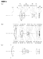
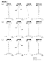
図6は、本実施例に係る撮像装置の備えるズームレンズの無限遠物点合焦時の構成を示す光軸に沿う断面図であり、(a)は広角端、(b)は中間、(c)は望遠端における状態をそれぞれ示している。図7は、図6に示したズームレンズを備えた撮像装置の無限遠物点合焦時における球面収差,非点収差,歪曲収差,倍率色収差を示す図であり、(a)は広角端、(b)は中間、(c)は望遠端における状態をそれぞれ示している。図8は、図6及び図7に示したズームレンズの光路を示す図であり、(a)は広角端、(b)は中間、(c)は望遠端における状態をそれぞれ示している。 FIG. 6 is a cross-sectional view along the optical axis showing the configuration of the zoom lens included in the imaging apparatus according to the present embodiment when focusing on an object point at infinity, where (a) is the wide-angle end, (b) is the middle, c) shows the state at the telephoto end. FIG. 7 is a diagram showing spherical aberration, astigmatism, distortion, and lateral chromatic aberration at the time of focusing on an object point at infinity of the imaging apparatus including the zoom lens shown in FIG. (B) shows the state at the middle, and (c) shows the state at the telephoto end. 8A and 8B are diagrams showing the optical path of the zoom lens shown in FIGS. 6 and 7, wherein FIG. 8A shows the state at the wide-angle end, FIG. 8B shows the state at the middle, and FIG. 8C shows the state at the telephoto end.
まず、図6を用いて、本実施例のズームレンズを備えた撮像装置の構成を説明する。本実施例のズームレンズを備えた撮像装置は、光軸Lc上に、物体側から順に、開口部材A、正の屈折力を持つ第1レンズ群G1、フレア絞りF、負の屈折力を持つ第2レンズ群G2、開口絞りS、正の屈折力を持つ第3レンズ群G3、正の屈折力を持つ第4レンズ群G4、撮像面IMを持つCCDが配置されている。なお、第4レンズ群G4とCCDとの間には、物体側から順に、平面平板状のローパスフィルターLPF、平面平板状のCCDカバーガラスCGが配置されている。 First, the configuration of an imaging apparatus including the zoom lens according to the present embodiment will be described with reference to FIG. The imaging apparatus including the zoom lens according to the present exemplary embodiment has an aperture member A, a first lens group G 1 having a positive refractive power, a flare stop F, and a negative refractive power in order from the object side on the optical axis Lc. A second lens group G 2 having an aperture stop S, a third lens group G 3 having a positive refractive power, a fourth lens group G 4 having a positive refractive power, and a CCD having an imaging surface IM are disposed. A flat plate-like low-pass filter LPF and a flat plate-like CCD cover glass CG are disposed between the fourth lens group G 4 and the CCD in order from the object side.
第1レンズ群G1は、物体側から順に、物体側に凸面を向けたメニスカスレンズであり負の屈折力を持つレンズL11と、像側の面が非球面の両凸レンズであり正の屈折力を持つレンズL12とにより構成されている。なお、レンズL11とレンズL12とは、接着剤により接合されている。 The first lens group G 1 is a meniscus lens having a convex surface directed toward the object side in order from the object side, a lens L 11 having negative refractive power, and a biconvex lens having an aspheric surface on the image side, and is positively refracted. And a lens L 12 having power. The lens L 11 and the lens L 12 are bonded with an adhesive.
第2レンズ群G2は、物体側から順に、両面が非球面の両凹レンズであり負の屈折力を持つレンズL21と、像側に凸面を向けたメニスカスレンズであり負の屈折力を持つレンズL22と、像側の面が非球面の両凹レンズであり負の屈折力を持つレンズL23とにより構成されている。なお、レンズL22とレンズL23とは、接着剤により接合されている。 The second lens group G 2 has in order from the object side, a lens L 21 having both surfaces with a negative refractive power is a biconcave aspheric, the negative refractive power is a meniscus lens having a convex surface directed toward the image side a lens L 22, the image side surface is constituted by the lens L 23 having a negative refractive power is a biconcave aspheric. The lens L 22 and the lens L 23 are bonded with an adhesive.
第3レンズ群G3は、物体側から順に、像側の面が非球面の両凸レンズであり正の屈折力を持つレンズL31と、両凸レンズであり正の屈折力を持つレンズL32と、両凹レンズであり負の屈折力を持つレンズL33とにより構成されている。なお、レンズL32とレンズL33とは、接着剤により接合されている。 The third lens group G 3 includes, in order from the object side, a lens L 31 having a positive refractive power and a biconvex lens having an aspheric surface on the image side, and a lens L 32 having a positive refractive power and a biconvex lens. The lens L 33 is a biconcave lens and has a negative refractive power. The lens L 32 and the lens L 33 are bonded with an adhesive.
第4レンズ群G4は、両面が非球面の両凸レンズであり正の屈折力を持つレンズL4のみにより構成されている。 The fourth lens group G 4 is composed only of a lens L 4 which is a biconvex lens having both aspheric surfaces and has positive refractive power.
また、広角端から望遠端に変倍する際に、第1レンズ群G1は、開口部材Aとフレア絞りFとともに光軸Lc上を物体側に移動する。第2レンズ群G2は、第1レンズ群G1との間隔を広げつつまず物体側に移動した後に像側に移動するようにして光軸Lc上を往復運動する。第3レンズ群G3は、明るさ絞りSとともに第2レンズ群G2との間隔を狭めつつ光軸Lc上を物体側に移動する。第4レンズ群G4は、第3レンズ群G3との間隔を広げつつまず像側に移動した後に物体側に移動するようにして光軸Lc上を往復運動する。 When zooming from the wide-angle end to the telephoto end, the first lens group G 1 moves along the optical axis Lc together with the aperture member A and the flare stop F toward the object side. The second lens group G 2 reciprocates on the optical axis Lc so as to first move to the object side and then move to the image side while increasing the distance from the first lens group G 1 . The third lens group G 3 moves along the optical axis Lc to the object side while narrowing the distance from the second lens group G 2 together with the aperture stop S. The fourth lens group G 4 reciprocates on the optical axis Lc so as to first move to the image side and then move to the object side while increasing the distance from the third lens group G 3 .
次に、本実施例に係る各光学系を構成するレンズの構成及び数値データを示す。なお、単位はmmである。 Next, the structure and numerical data of the lens which comprises each optical system based on a present Example are shown. The unit is mm.
面データ
面番号 曲率半径 面間隔 屈折率 アッベ数
R D Nd νd
1 (開口部材) ∞ 1.30
2 24.303 0.60 1.94595 17.98
3 20.278 0.01 1.56384 60.67
4 20.278 3.86 1.59201 67.02
5 (非球面) -83.332 0.00
6 (フレア絞り) ∞ D6
7 (非球面) -219.382 0.80 1.85135 40.10
8 (非球面) 7.253 2.75
9 -48.761 1.82 1.94595 17.98
10 -12.340 0.01 1.56384 60.67
11 -12.340 0.70 1.77377 47.17
12 (非球面) 263.939 D12
13 (開口絞り) ∞ 0.00
14 (非球面) 4.672 2.50 1.59201 67.02
15 (非球面) -25.291 0.10
16 8.562 1.70 1.49700 81.54
17 -9.402 0.01 1.56384 60.67
18 -9.402 0.42 1.62004 36.26
19 3.399 D19
20 (非球面) 20.655 2.76 1.58313 59.38
21 (非球面) -14.163 D21
22 ∞ 0.40 1.54771 62.84
23 ∞ 0.50
24 ∞ 0.50 1.51633 64.14
25 ∞ 0.37
26 (撮像面) ∞
Surface data Surface number Curvature radius Surface spacing Refractive index Abbe number
R D Nd νd
1 (Opening member) ∞ 1.30
2 24.303 0.60 1.94595 17.98
3 20.278 0.01 1.56384 60.67
4 20.278 3.86 1.59201 67.02
5 (Aspherical surface) -83.332 0.00
6 (Flare aperture) ∞ D6
7 (Aspherical surface) -219.382 0.80 1.85135 40.10
8 (Aspherical surface) 7.253 2.75
9 -48.761 1.82 1.94595 17.98
10 -12.340 0.01 1.56384 60.67
11 -12.340 0.70 1.77377 47.17
12 (Aspherical) 263.939 D12
13 (Aperture stop) ∞ 0.00
14 (Aspherical surface) 4.672 2.50 1.59201 67.02
15 (Aspherical surface) -25.291 0.10
16 8.562 1.70 1.49700 81.54
17 -9.402 0.01 1.56384 60.67
18 -9.402 0.42 1.62004 36.26
19 3.399 D19
20 (Aspherical) 20.655 2.76 1.58313 59.38
21 (Aspherical surface) -14.163 D21
22 ∞ 0.40 1.54771 62.84
23 ∞ 0.50
24 ∞ 0.50 1.51633 64.14
25 ∞ 0.37
26 (Imaging surface) ∞
非球面データ
面番号 曲率半径 円錐係数
R K
5 -83.332 0.000
非球面係数
A4 A6 A8 A10 A12
1.01931e-05 -1.99182e-08 2.10982e-10 -1.07813e-12
面番号 曲率半径 円錐係数
R K
7 -219.382 0.000
非球面係数
A4 A6 A8 A10 A12
-7.79808e-05 -9.78436e-07 2.06198e-08 4.17971e-10 -9.04989e-12
面番号 曲率半径 円錐係数
R K
8 7.253 0.108
非球面係数
A4 A6 A8 A10 A12
3.53561e-05 1.81435e-06 -4.09283e-07 1.46449e-08 -4.48012e-10
面番号 曲率半径 円錐係数
R K
12 263.939 -8.501
非球面係数
A4 A6 A8 A10 A12
-2.84161e-04 -3.58819e-06 2.07140e-07
面番号 曲率半径 円錐係数
R K
14 4.672 0.000
非球面係数
A4 A6 A8 A10 A12
-4.28460e-04 2.56408e-05 -7.90463e-07 2.10375e-07 2.49609e-08
面番号 曲率半径 円錐係数
R K
15 -25.291 0.000
非球面係数
A4 A6 A8 A10 A12
1.14651e-03 7.78099e-05 -4.88552e-06 1.20734e-06 3.25505e-08
面番号 曲率半径 円錐係数
R K
20 20.655 2.172
非球面係数
A4 A6 A8 A10 A12
8.48827e-06 1.27088e-06 -4.12476e-07 7.62650e-09
面番号 曲率半径 円錐係数
R K
21 -14.163 -0.705
非球面係数
A4 A6 A8 A10 A12
6.34913e-05 -5.55093e-06 -2.18822e-07 5.67198e-09
Aspheric data
Surface number Curvature radius Conical coefficient
RK
5 -83.332 0.000
Aspheric coefficient
AFour A6 A8 ATen A12
1.01931e-05 -1.99182e-08 2.10982e-10 -1.07813e-12
Surface number Curvature radius Conical coefficient
RK
7 -219.382 0.000
Aspheric coefficient
AFour A6 A8 ATen A12
-7.79808e-05 -9.78436e-07 2.06198e-08 4.17971e-10 -9.04989e-12
Surface number Curvature radius Conical coefficient
RK
8 7.253 0.108
Aspheric coefficient
AFour A6 A8 ATen A12
3.53561e-05 1.81435e-06 -4.09283e-07 1.46449e-08 -4.48012e-10
Surface number Curvature radius Conical coefficient
RK
12 263.939 -8.501
Aspheric coefficient
AFour A6 A8 ATen A12
-2.84161e-04 -3.58819e-06 2.07140e-07
Surface number Curvature radius Conical coefficient
RK
14 4.672 0.000
Aspheric coefficient
AFour A6 A8 ATen A12
-4.28460e-04 2.56408e-05 -7.90463e-07 2.10375e-07 2.49609e-08
Surface number Curvature radius Conical coefficient
RK
15 -25.291 0.000
Aspheric coefficient
AFour A6 A8 ATen A12
1.14651e-03 7.78099e-05 -4.88552e-06 1.20734e-06 3.25505e-08
Surface number Curvature radius Conical coefficient
RK
20 20.655 2.172
Aspheric coefficient
AFour A6 A8 ATen A12
8.48827e-06 1.27088e-06 -4.12476e-07 7.62650e-09
Surface number Curvature radius Conical coefficient
RK
21 -14.163 -0.705
Aspheric coefficient
AFour A6 A8 ATen A12
6.34913e-05 -5.55093e-06 -2.18822e-07 5.67198e-09
各種データ
ズーム比 9.60
広角 中間 望遠
焦点距離 5.12 15.93 49.16
Fナンバー 3.29 5.49 6.00
画角 79.91 27.16 9.03
像高 3.62 3.87 3.88
レンズ全長 41.84 53.45 58.92
バックフォーカス 6.02 4.25 4.66
D6 0.30 8.86 18.86
D12 15.35 8.83 1.44
D19 2.15 13.51 15.94
D21 4.51 2.83 3.17
Various data Zoom ratio 9.60
Wide angle Medium telephoto Focal length 5.12 15.93 49.16
F number 3.29 5.49 6.00
Angle of view 79.91 27.16 9.03
Image height 3.62 3.87 3.88
Total lens length 41.84 53.45 58.92
Back focus 6.02 4.25 4.66
D6 0.30 8.86 18.86
D12 15.35 8.83 1.44
D19 2.15 13.51 15.94
D21 4.51 2.83 3.17
ズームレンズ群データ
群 始面 焦点距離
1 2 35.31
2 7 -7.62
3 14 11.31
4 20 14.84
Zoom lens group data Group Start surface Focal length
1 2 35.31
2 7 -7.62
3 14 11.31
4 20 14.84
上記条件式に係るデータ
条件式(1) (XA/YA)/(XF/YF) < 1.10 : 1.01
条件式(2) (XI/YI)/(XF/YF) < 1.10 : 1.00
条件式(3) 0.5 < fw/D < 1 : 0.66
条件式(4) 4.5 < ft/fw < 50 : 9.60
Data Conditional Expression (1) According to the Conditional Expression (X A / Y A ) / (X F / Y F ) <1.10: 1.01
Conditional expression (2) (X I / Y I ) / (X F / Y F ) <1.10: 1.00
Conditional expression (3) 0.5 <fw / D <1: 0.66
Conditional expression (4) 4.5 <ft / fw <50: 9.60
図9は、本実施例に係る撮像装置の備えるズームレンズの無限遠物点合焦時の構成を示す光軸に沿う断面図であり、(a)は広角端、(b)は中間、(c)は望遠端における状態をそれぞれ示している。図10は、図9に示したズームレンズを備えた撮像装置の無限遠物点合焦時における球面収差,非点収差,歪曲収差,倍率色収差を示す図であり、(a)は広角端、(b)は中間、(c)は望遠端における状態をそれぞれ示している。図11は、図9及び図10に示したズームレンズの光路を示す図であり、(a)は広角端、(b)は中間、(c)は望遠端における状態をそれぞれ示している。 FIG. 9 is a cross-sectional view of the zoom lens included in the imaging apparatus according to the present embodiment along the optical axis showing the configuration at the time of focusing on an object point at infinity, where (a) is the wide-angle end, (b) is the middle, c) shows the state at the telephoto end. FIG. 10 is a diagram showing spherical aberration, astigmatism, distortion, and lateral chromatic aberration at the time of focusing on an object point at infinity of the imaging apparatus including the zoom lens shown in FIG. (B) shows the state at the middle, and (c) shows the state at the telephoto end. 11A and 11B are diagrams showing optical paths of the zoom lens shown in FIGS. 9 and 10, wherein FIG. 11A shows a state at the wide-angle end, FIG. 11B shows an intermediate state, and FIG. 11C shows a state at the telephoto end.
まず、図8を用いて、本実施例のズームレンズを備えた撮像装置の構成を説明する。本実施例のズームレンズを備えた撮像装置は、光軸Lc上に、物体側から順に、開口部材A、正の屈折力を持つ第1レンズ群G1、フレア絞りF、負の屈折力を持つ第2レンズ群G2、開口絞りS、正の屈折力を持つ第3レンズ群G3、正の屈折力を持つ第4レンズ群G4、撮像面IMを持つCCDが配置されている。また、第4レンズ群G4とCCDとの間には、物体側から順に、平面平板状のローパスフィルターLPF、平面平板状のCCDカバーガラスCGが配置されている。 First, the configuration of an image pickup apparatus including the zoom lens according to the present embodiment will be described with reference to FIG. The imaging apparatus including the zoom lens according to the present exemplary embodiment has an aperture member A, a first lens group G 1 having a positive refractive power, a flare stop F, and a negative refractive power in order from the object side on the optical axis Lc. A second lens group G 2 having an aperture stop S, a third lens group G 3 having a positive refractive power, a fourth lens group G 4 having a positive refractive power, and a CCD having an imaging surface IM are disposed. Further, between the fourth lens group G 4 and the CCD, a flat plate-like low pass filter LPF and a flat plate-like CCD cover glass CG are arranged in this order from the object side.
第1レンズ群G1は、物体側から順に、物体側に凸面を向けたメニスカスレンズであり負の屈折力を持つレンズL11と、像側の面が非球面の両凸レンズであり正の屈折力を持つレンズL12とにより構成されている。なお、レンズL11とレンズL12とは、接着剤により接合されている。 The first lens group G 1 is a meniscus lens having a convex surface directed toward the object side in order from the object side, a lens L 11 having negative refractive power, and a biconvex lens having an aspheric surface on the image side, and is positively refracted. And a lens L 12 having power. The lens L 11 and the lens L 12 are bonded with an adhesive.
第2レンズ群G2は、物体側から順に、両面が非球面の両凹レンズであり負の屈折力を持つレンズL21と、像側に凸面を向けたメニスカスレンズであり負の屈折力を持つレンズL22と、像側の面が非球面の両凹レンズであり負の屈折力を持つレンズL23とにより構成されている。なお、レンズL22とレンズL23とは、接着剤により接合されている。 The second lens group G 2 has in order from the object side, a lens L 21 having both surfaces with a negative refractive power is a biconcave aspheric, the negative refractive power is a meniscus lens having a convex surface directed toward the image side a lens L 22, the image side surface is constituted by the lens L 23 having a negative refractive power is a biconcave aspheric. The lens L 22 and the lens L 23 are bonded with an adhesive.
第3レンズ群G3は、物体側から順に、像側の面が非球面の両凸レンズであり正の屈折力を持つレンズL31と、両凸レンズであり正の屈折力を持つレンズL32と、両凹レンズであり負の屈折力を持つレンズL33とにより構成されている。なお、レンズL32とレンズL33とは、接着剤により接合されている。 The third lens group G 3 includes, in order from the object side, a lens L 31 having a positive refractive power and a biconvex lens having an aspheric surface on the image side, and a lens L 32 having a positive refractive power and a biconvex lens. The lens L 33 is a biconcave lens and has a negative refractive power. The lens L 32 and the lens L 33 are bonded with an adhesive.
第4レンズ群G4は、両面が非球面の両凸レンズであり正の屈折力を持つレンズL4のみにより構成されている。 The fourth lens group G 4 is composed only of a lens L 4 which is a biconvex lens having both aspheric surfaces and has positive refractive power.
また、広角端から望遠端に変倍する際に、第1レンズ群G1は、開口部材Aとフレア絞りFとともに光軸Lc上を物体側に移動する。第2レンズ群G2は、第1レンズ群G1との間隔を広げつつまず物体側に移動した後に像側に移動するようにして光軸Lc上を往復運動する。第3レンズ群G3は、明るさ絞りSとともに第2レンズ群G2との間隔を狭めつつ光軸Lc上を物体側に移動する。第4レンズ群G4は、第3レンズ群G3との間隔を広げつつまず像側に移動した後に物体側に移動するようにして光軸Lc上を往復運動する。 When zooming from the wide-angle end to the telephoto end, the first lens group G 1 moves along the optical axis Lc together with the aperture member A and the flare stop F toward the object side. The second lens group G 2 reciprocates on the optical axis Lc so as to first move to the object side and then move to the image side while increasing the distance from the first lens group G 1 . The third lens group G 3 moves along the optical axis Lc to the object side while narrowing the distance from the second lens group G 2 together with the aperture stop S. The fourth lens group G 4 reciprocates on the optical axis Lc so as to first move to the image side and then move to the object side while increasing the distance from the third lens group G 3 .
なお、フレア絞りFは、その面が、光軸上において、第1レンズ群G1の最も像側のレンズであるレンズL22の像側の面の頂点の位置と、レンズL22の像側の面の外縁の位置との間になるようにして配置されている。 The surface of the flare stop F has an apex position on the image side surface of the lens L 22 which is the most image side lens of the first lens group G 1 on the optical axis, and the image side of the lens L 22 . It arrange | positions so that it may be between the position of the outer edge of the surface of this.
次に、本実施例に係る各光学系を構成するレンズの構成及び数値データを示す。なお、単位はmmである。 Next, the structure and numerical data of the lens which comprises each optical system based on a present Example are shown. The unit is mm.
面データ
面番号 曲率半径 面間隔 屈折率 アッベ数
R D Nd νd
1 (開口部) ∞ 1.50
2 23.990 0.60 1.94595 17.98
3 20.014 0.01 1.56384 60.67
4 20.014 3.61 1.59201 67.02
5 (非球面) -81.633 -0.28
6 (フレア絞り) ∞ 0.28
7 ∞ D7
8 (非球面) -119.663 0.80 1.85135 40.10
9 (非球面) 7.135 2.77
10 -49.115 1.72 1.94595 17.98
11 -12.221 0.01 1.56384 60.67
12 -12.221 0.70 1.77377 47.17
13 (非球面) 1391.402 D13
14 (開口絞り) ∞ 0.00
15 (非球面) 4.647 2.44 1.59201 67.02
16 (非球面) -25.229 0.10
17 (非球面) 8.387 1.69 1.49700 81.54
18 -9.072 0.01 1.56384 60.67
19 -9.072 0.41 1.62004 36.26
20 3.398 D20
21 (非球面) 17.586 2.64 1.53113 55.80
22 (非球面) -13.846 D23
23 ∞ 0.40 1.54771 62.84
24 ∞ 0.50
25 ∞ 0.50 1.51633 64.14
26 ∞ 0.37
27 (撮像面) ∞
なお、面番号5に係る面間隔は、第1レンズ群の最も像側のレンズの像側の面である面番号5の面から、フレア絞りである面番号6の面までの距離であり、面番号6に係る面間隔は、フレア絞りである面番号6の面から、第1レンズ群の最も像側のレンズの像側の面である面番号7(面番号5)の面までの距離である。
Surface data Surface number Curvature radius Surface spacing Refractive index Abbe number
R D Nd νd
1 (Opening) ∞ 1.50
2 23.990 0.60 1.94595 17.98
3 20.014 0.01 1.56384 60.67
4 20.014 3.61 1.59201 67.02
5 (Aspherical surface) -81.633 -0.28
6 (Flare aperture) ∞ 0.28
7 ∞ D7
8 (Aspherical surface) -119.663 0.80 1.85135 40.10
9 (Aspherical surface) 7.135 2.77
10 -49.115 1.72 1.94595 17.98
11 -12.221 0.01 1.56384 60.67
12 -12.221 0.70 1.77377 47.17
13 (Aspherical) 1391.402 D13
14 (Aperture stop) ∞ 0.00
15 (Aspherical surface) 4.647 2.44 1.59201 67.02
16 (Aspherical surface) -25.229 0.10
17 (Aspherical surface) 8.387 1.69 1.49700 81.54
18 -9.072 0.01 1.56384 60.67
19 -9.072 0.41 1.62004 36.26
20 3.398 D20
21 (Aspherical) 17.586 2.64 1.53113 55.80
22 (Aspherical surface) -13.846 D23
23 ∞ 0.40 1.54771 62.84
24 ∞ 0.50
25 ∞ 0.50 1.51633 64.14
26 ∞ 0.37
27 (Imaging surface) ∞
The surface interval related to
非球面データ
面番号 曲率半径 円錐係数
R K
5 -81.633 0.000
非球面係数
A4 A6 A8 A10 A12
1.07975e-05 -2.33198e-08 2.23143e-10 -1.11486e-12
面番号 曲率半径 円錐係数
R K
8 -119.663 0.000
非球面係数
A4 A6 A8 A10 A12
6.97736e-06 -1.51633e-06 -6.73939e-09 1.12137e-09 -1.53525e-11
面番号 曲率半径 円錐係数
R K
9 7.135 0.000
非球面係数
A4 A6 A8 A10 A12
1.61852e-04 5.23127e-06 -1.40862e-07 4.39299e-09 -4.10602e-10
面番号 曲率半径 円錐係数
R K
13 1391.402 0.000
非球面係数
A4 A6 A8 A10 A12
-2.83385e-04 -5.68516e-06 8.44218e-08 1.07571e-08 -2.27133e-10
面番号 曲率半径 円錐係数
R K
15 4.647 0.000
非球面係数
A4 A6 A8 A10 A12
-3.57433e-04 1.75624e-05 1.81288e-06 -5.08442e-09 4.08679e-08
面番号 曲率半径 円錐係数
R K
16 -25.229 0.000
非球面係数
A4 A6 A8 A10 A12
1.26421e-03 5.98140e-05 3.66397e-06 6.18940e-09 1.23571e-07
面番号 曲率半径 円錐係数
R K
21 17.586 1.000
非球面係数
A4 A6 A8 A10 A12
7.35861e-05 4.19366e-06 -1.25570e-06 6.02317e-08 -9.47479e-10
面番号 曲率半径 円錐係数
R K
22 -13.846 -0.664
非球面係数
A4 A6 A8 A10 A12
1.69596e-04 -1.68121e-05 2.77678e-07 -2.47101e-09 1.25457e-10
Aspheric data Surface number Curvature radius Conical coefficient
RK
5 -81.633 0.000
Aspheric coefficient
A 4 A 6 A 8 A 10 A 12
1.07975e-05 -2.33198e-08 2.23143e-10 -1.11486e-12
Surface number Curvature radius Conical coefficient
RK
8 -119.663 0.000
Aspheric coefficient
A 4 A 6 A 8 A 10 A 12
6.97736e-06 -1.51633e-06 -6.73939e-09 1.12137e-09 -1.53525e-11
Surface number Curvature radius Conical coefficient
RK
9 7.135 0.000
Aspheric coefficient
A 4 A 6 A 8 A 10 A 12
1.61852e-04 5.23127e-06 -1.40862e-07 4.39299e-09 -4.10602e-10
Surface number Curvature radius Conical coefficient
RK
13 1391.402 0.000
Aspheric coefficient
A 4 A 6 A 8 A 10 A 12
-2.83385e-04 -5.68516e-06 8.44218e-08 1.07571e-08 -2.27133e-10
Surface number Curvature radius Conical coefficient
RK
15 4.647 0.000
Aspheric coefficient
A 4 A 6 A 8 A 10 A 12
-3.57433e-04 1.75624e-05 1.81288e-06 -5.08442e-09 4.08679e-08
Surface number Curvature radius Conical coefficient
RK
16 -25.229 0.000
Aspheric coefficient
A 4 A 6 A 8 A 10 A 12
1.26421e-03 5.98140e-05 3.66397e-06 6.18940e-09 1.23571e-07
Surface number Curvature radius Conical coefficient
RK
21 17.586 1.000
Aspheric coefficient
A 4 A 6 A 8 A 10 A 12
7.35861e-05 4.19366e-06 -1.25570e-06 6.02317e-08 -9.47479e-10
Surface number Curvature radius Conical coefficient
RK
22 -13.846 -0.664
Aspheric coefficient
A 4 A 6 A 8 A 10 A 12
1.69596e-04 -1.68121e-05 2.77678e-07 -2.47101e-09 1.25457e-10
各種データ
ズーム比 9.61
広角 中間 望遠
焦点距離 5.06 16.07 48.63
Fナンバー 3.27 5.66 6.00
画角 80.14 26.87 9.00
像高 3.56 3.82 3.82
レンズ全長 41.14 52.33 57.90
バックフォーカス 5.87 4.12 4.37
D7 0.30 8.03 18.61
D13 15.14 8.21 1.38
D20 2.33 14.48 16.03
D22 4.36 2.69 2.88
Various data Zoom ratio 9.61
Wide angle Medium telephoto Focal length 5.06 16.07 48.63
F number 3.27 5.66 6.00
Angle of view 80.14 26.87 9.00
Image height 3.56 3.82 3.82
Total lens length 41.14 52.33 57.90
Back focus 5.87 4.12 4.37
D7 0.30 8.03 18.61
D13 15.14 8.21 1.38
D20 2.33 14.48 16.03
D22 4.36 2.69 2.88
ズームレンズ群データ
群 始面 焦点距離
1 2 34.77
2 8 -7.53
3 15 11.16
4 21 15.02
Zoom lens group data Group Start surface Focal length
1 2 34.77
2 8 -7.53
3 15 11.16
4 21 15.02
上記条件式に係るデータ
条件式(1) (XA/YA)/(XF/YF) < 1.10 : 1.07
条件式(2) (XI/YI)/(XF/YF) < 1.10 : 1.05
条件式(3) 0.5 < fw/D < 1 : 0.65
条件式(4) 4.5 < ft/fw < 50 : 9.61
Data Conditional Expression (1) According to the Conditional Expression (1) (X A / Y A ) / (X F / Y F ) <1.10: 1.07
Conditional expression (2) (X I / Y I ) / (X F / Y F ) <1.10: 1.05
Conditional expression (3) 0.5 <fw / D <1: 0.65
Conditional expression (4) 4.5 <ft / fw <50: 9.61
なお、上記各実施例においては、撮像素子、開口部材の開口部、フレア絞りの開口部の形状は、それぞれ略矩形であるが、そのような形状に限られるものではない。 In each of the above embodiments, the shapes of the imaging element, the opening of the opening member, and the opening of the flare stop are substantially rectangular, but are not limited to such shapes.
また、本発明に係る撮像装置は、以下のように構成しても良い。 The imaging device according to the present invention may be configured as follows.
本発明に係る撮像装置は、撮像素子で得られた画像データを、倍率色収差による色のずれを補正した画像データに変換する画像変換部を備えることが好ましい。このように画像変換部を備える構成とすれば、撮像装置の備えるズームレンズによる倍率色収差を電気的に補正することにより、さらに良好な画像を得ることができるようになる。 The image pickup apparatus according to the present invention preferably includes an image conversion unit that converts image data obtained by the image pickup device into image data in which color shift due to lateral chromatic aberration is corrected. With the configuration including the image conversion unit as described above, it is possible to obtain a better image by electrically correcting the chromatic aberration of magnification due to the zoom lens included in the imaging apparatus.
一般に、デジタルカメラでは、被写体の像を第1原色,第2原色,第3原色の3原色の像に分解して、それぞれの出力信号を演算により重ね合わせてカラー画像を再現するようにしている。しかし、ズームレンズに倍率色収差がある場合、第1原色の光による像を基準にして考えると、第2原色と第3原色の光による像の結像位置は第1原色の像の結像位置からずれることになる。 In general, in a digital camera, an image of a subject is separated into three primary color images of a first primary color, a second primary color, and a third primary color, and each output signal is overlapped by calculation to reproduce a color image. . However, when the zoom lens has lateral chromatic aberration, the image formation position of the image of the first primary color is the image formation position of the image of the first primary color, considering the image of the light of the first primary color as a reference. It will deviate from.
そのようなずれの原因となる倍率色収差を電子的に補正するためには、第1原色に対する第2原色や第3原色の像の結像位置のずれの量を、撮像素子の各画素ごとにズームレンズの収差情報に基いて予め求めておき、各画素ごとに第1原色の像の結像位置とのずれの量だけ補正するよう座標変換を行ってやればよい。 In order to electronically correct the lateral chromatic aberration that causes such a shift, the amount of shift in the imaging position of the image of the second primary color or the third primary color with respect to the first primary color is determined for each pixel of the image sensor. Coordinate conversion may be performed in advance based on the aberration information of the zoom lens so that the amount of deviation from the image forming position of the first primary color image is corrected for each pixel.
例えば、赤(R),緑(G),青(B)の3原色の出力信号からなる画像の場合、緑(G)に対する赤(R)と青(B)の像の結像位置のずれの量を各画素について求めておき、緑(G)の像の結像位置とのずれがなくなるように撮影画像の座標変換を行い、その後に赤(R)と青(B)の信号を出力してやればよい。 For example, in the case of an image composed of output signals of three primary colors of red (R), green (G), and blue (B), the image formation position shift of the red (R) and blue (B) images with respect to green (G) Is obtained for each pixel, coordinate conversion of the captured image is performed so that there is no deviation from the image formation position of the green (G) image, and then red (R) and blue (B) signals are output. Just do it.
なお、倍率色収差はズーム、フォーカス、絞り値によって変化するが、各レンズポジション(ズーム、フォーカス、絞り値)ごとに、この第1原色からの第2原色および第3原色のずれ量を補正データとして記憶保持装置に記憶させておくと良い。ズームポジションに応じてこの補正データを参照すれば、第1原色信号に対する第2及び第3原色のずれを補正した第2及び第3原色信号を出力することができる。 Note that the chromatic aberration of magnification changes depending on the zoom, focus, and aperture value, but for each lens position (zoom, focus, and aperture value), the deviation amounts of the second primary color and the third primary color from the first primary color are used as correction data. It may be stored in a memory holding device. By referring to the correction data according to the zoom position, it is possible to output the second and third primary color signals in which the deviation between the second and third primary colors with respect to the first primary color signal is corrected.
また、本発明に係る撮像装置は、ズームレンズのピント調節を行うためのフォーカシングを、ズームレンズを構成する複数のレンズ群のうち、最も像側のレンズ群で行うことが望ましい。そのような位置に配置されているレンズ群はレンズ重量が軽量であるため、フォーカシングの際にモータにかかる負荷が少ない。さらに、フォーカシング時に全長が変化せず、鏡枠内部に駆動モータを配置することもできるし、鏡枠を小型化することもできる。 In the image pickup apparatus according to the present invention, it is preferable that focusing for performing focus adjustment of the zoom lens is performed on a lens group closest to the image among a plurality of lens groups constituting the zoom lens. Since the lens group arranged at such a position has a light weight, the load applied to the motor during focusing is small. Further, the total length does not change during focusing, and a drive motor can be arranged inside the lens frame, and the lens frame can be downsized.
なお、フォーカシングは、上述のように最も像側のレンズ群により行うことが望ましいが、他のレンズ群で行っても良い。また、複数のレンズ群で行っても良い。この場合には、フォーカシングのよる性能劣化をより効率的に抑えることができる。また、そのフォーカシングは、ズームレンズ全体を移動させて行っても良いし、一つのレンズ群の一部のレンズを移動させて行っても良い。 As described above, focusing is preferably performed by the lens group closest to the image side, but may be performed by another lens group. Further, a plurality of lens groups may be used. In this case, performance degradation due to focusing can be suppressed more efficiently. Further, the focusing may be performed by moving the entire zoom lens or by moving some lenses of one lens group.
また、本発明に係る撮像装置は、画像周辺部の明るさのかげり(シェーディング)を、CCDのマイクロレンズをシフトすることにより軽減しても良い。例えば、各像高における光線の入射角に合わせてCCDのマイクロレンズの設計を変えても良い。また、画像処理により画像周辺部の低下量を補正しても良い。 Further, the imaging apparatus according to the present invention may reduce the brightness (shading) in the peripheral portion of the image by shifting the CCD microlens. For example, the design of the CCD microlens may be changed according to the incident angle of the light beam at each image height. Further, the amount of decrease in the peripheral portion of the image may be corrected by image processing.
本発明に係る撮像装置のフレア絞りは、枠部材を用いて構成しても良いし、別の部材を用いて構成しても良い。さらに、フレア絞りは、光学部材に直接印刷で構成しても良いし、塗料や接着シール等を用いて構成しても良い。また、フレア絞りは、有害光束をカットするだけでなく画面周辺のコマフレア等の光束をカットするようにしても良い。 The flare stop of the imaging apparatus according to the present invention may be configured using a frame member, or may be configured using another member. Furthermore, the flare stop may be configured by printing directly on the optical member, or may be configured using a paint, an adhesive seal, or the like. Further, the flare stop may cut not only harmful light flux but also light flux such as coma flare around the screen.
また、本発明に係る撮像装置に備えられているズームレンズの各レンズには、反射防止コートを施し、ゴースト・フレアを軽減するようにしても良い。その場合、さらに、効果的にゴースト・フレアを軽減するためには、施す反射防止コートを、マルチコートとすることが望ましい。また、赤外カットコートを、ローパスフィルターにではなく、各レンズのレンズ面やカバーガラス等に施しても良い。 In addition, each lens of the zoom lens provided in the image pickup apparatus according to the present invention may be provided with an antireflection coating to reduce ghost and flare. In that case, in order to further effectively reduce ghost and flare, it is desirable that the antireflection coat to be applied is a multi-coat. Further, the infrared cut coat may be applied not to the low-pass filter but to the lens surface of each lens, a cover glass, or the like.
なお、ゴースト・フレアの発生を防止するためにレンズの空気接触面に反射防止コートを施すことが一般的に行われている。一方、接合レンズの接合面における接着剤の屈折率は空気の屈折率よりも十分高い。そのため、接合レンズの接合面は、もともと単層コート並み、あるいはそれ以下の反射率となっていることが多いので、あえてコートを施すことは少ない。しかし、接合レンズの接合面にも積極的に反射防止コートを施せば、さらにゴースト・フレアを軽減することができ、さらに良好な画像を得ることができるようになる。 In order to prevent the occurrence of ghosts and flares, an antireflection coating is generally applied to the air contact surface of the lens. On the other hand, the refractive index of the adhesive on the cemented surface of the cemented lens is sufficiently higher than the refractive index of air. For this reason, the cemented surface of the cemented lens often has a reflectance equivalent to or less than that of a single-layer coating from the beginning. However, if an anti-reflection coating is positively applied to the cemented surface of the cemented lens, ghosts and flares can be further reduced, and a better image can be obtained.
特に、最近では、高い収差補正効果の得られる高屈折率硝材が普及し、カメラ用光学系にも多用されるようになってきているが、高屈折率硝材を接合レンズに用いた場合には、接合面での反射も無視できなくなってくる。そのため、そのような場合には、接合面にも反射防止コートを施しておくと効果的である。 In particular, recently, high refractive index glass materials capable of obtaining a high aberration correction effect have become widespread and have been widely used in camera optical systems. However, when high refractive index glass materials are used for cemented lenses, The reflection at the joint surface cannot be ignored. Therefore, in such a case, it is effective to apply an antireflection coating to the joint surface.
このような接合面に対する効果的なコーティング方法に関しては、特開平2−27301号公報,特開2001−324676号公報,特開2005−92115号公報,USP第7116482号明細書等に開示されている。使用するコート材としては、基材となるレンズの屈折率と接着剤の屈折率に応じて、比較的高屈折率の得られるTa2O5,TiO2,Nb2O5,ZrO2,HfO2,CeO2,SnO2,In2O3,ZnO,Y2O3などのコート材、比較的低屈折率の得られるMgF2,SiO2,Al2O3などのコート材等を適宜選択し、位相条件を満たすような膜厚に設定すれば良い。 Such an effective coating method for the joint surface is disclosed in JP-A-2-27301, JP-A-2001-324676, JP-A-2005-92115, USP 7116482, and the like. . As a coating material to be used, Ta 2 O 5 , TiO 2 , Nb 2 O 5 , ZrO 2 , HfO which can obtain a relatively high refractive index according to the refractive index of the lens serving as the base material and the refractive index of the adhesive. 2 , CoO 2 , SnO 2 , In 2 O 3 , ZnO, Y 2 O 3, etc., coating materials such as MgF 2 , SiO 2 , Al 2 O 3, etc. with which a relatively low refractive index can be obtained, etc. The film thickness may be set to satisfy the phase condition.
また、当然のことながら、レンズの空気接触面へのコートと同様、接合面へのコートをマルチコートとしても良い。その場合、各層のコート材や膜厚を適宜組み合わせることにより、さらなる反射率の低減や、反射率の分光特性・角度特性等のコントロール等を行うことが可能となる。 As a matter of course, the coating on the cemented surface may be a multi-coat as in the case of the coating on the air contact surface of the lens. In that case, by further combining the coating materials and film thicknesses of the respective layers, it is possible to further reduce the reflectance and control the spectral characteristics and angular characteristics of the reflectance.
A 開口部材
Aa 開口部材の開口部
CG カバーガラス
F フレア絞り
Fa フレア絞りの開口部
G1 第1レンズ群
G2 第2レンズ群
G3 第3レンズ群
G4 第4レンズ群
IM 撮像面
L11,L12,L21,L22,L23,L31,L32,L33,L34,L4 レンズ
Lc 光軸
LF 光束
LFW 広角端のときの開口部材における有効光束
LFW’ 広角端のときのフレア絞りにおける有効光束
LFT 望遠端のときの開口部材における有効光束
LFT’ 望遠端のときのフレア絞りにおける有効光束
LPF ローパスフィルター
PR 主光線
S 開口絞り
A opening member A a opening CG cover glass F flare stop F a opening G 1 first lens group G 2 the second lens group G 3 third lens group G 4 fourth lens group IM imaging surface of flare stop opening member L 11 , L 12 , L 21 , L 22 , L 23 , L 31 , L 32 , L 33 , L 34 , L 4 lens Lc Optical axis LF Light flux LF W Effective light flux at the aperture member at the wide angle end LF W ' Effective beam at the flare stop at the wide angle end LF T Effective beam at the aperture member at the telephoto end LF T 'Effective beam at the flare stop at the telephoto end LPF Low-pass filter PR Main ray S Aperture stop
Claims (6)
所定の形状の開口部を有するフレア絞りが、前記複数のレンズ群のうち最も物体側にあるレンズ群と一体的に設けられており、
前記開口部材の開口部が、広角端のときには有効光束を遮断せず、かつ、望遠端のときには有効光束の一部を遮断し、
前記フレア絞りが、広角端のときには前記開口部材の開口部を通過した有効光束を遮断せず、かつ、望遠端のときには前記開口部材の開口部を通過した有効光束のうち前記開口部材の開口部の淵に当たって散乱した光を遮断することを特徴とする撮像装置。 In an imaging apparatus including an aperture member having an aperture, and a zoom lens that changes magnification by appropriately changing the interval between a plurality of lens groups, and an imaging element, in order from the object side.
A flare stop having an opening of a predetermined shape is provided integrally with the lens group closest to the object among the plurality of lens groups,
When the aperture of the aperture member is at the wide-angle end, it does not block the effective luminous flux, and when the aperture is at the telephoto end, it blocks a part of the effective luminous flux,
When the flare stop is at the wide-angle end, it does not block the effective light beam that has passed through the opening of the opening member, and when the flare stop is at the telephoto end, the opening of the opening member out of the effective light beam that has passed through the opening of the opening member An image pickup apparatus that blocks light scattered upon hitting the eyelid.
次の条件式(1)を満たすことを特徴とする請求項1に記載の撮像装置。
(XA/YA)/(XF/YF) < 1.10 ・・・(1)
ただし、前記撮像素子の有効撮像領域の長手方向をX方向、前記撮像素子の有効撮像領域の長手方向と直交する方向をY方向とし、XAは前記開口部材の有する開口部のX方向の最大値、YAは前記開口部材の有する開口部のY方向の最大値、XFは前記フレア絞りの有する開口部のX方向の最大値、YFは前記フレア絞りの有する開口部のY方向の最大値である。 The opening of the opening member, the opening of the flare stop, and the effective imaging area of the imaging device are substantially rectangular,
The imaging apparatus according to claim 1, wherein the following conditional expression (1) is satisfied.
(X A / Y A ) / (X F / Y F ) <1.10 (1)
However, the longitudinal direction of the effective imaging region of the imaging device is the X direction, the direction orthogonal to the longitudinal direction of the effective imaging region of the imaging device is the Y direction, and X A is the maximum in the X direction of the opening of the opening member. Y A is the maximum value in the Y direction of the opening of the aperture member, X F is the maximum value in the X direction of the opening of the flare stop, and Y F is the Y direction of the opening of the flare stop. It is the maximum value.
次の条件式(2)を満足することを特徴とする請求項1又は2に記載の撮像装置。
(XI/YI)/(XF/YF) < 1.10 ・・・(2)
ただし、前記撮像素子の有効撮像領域の長手方向をX方向、前記撮像素子の有効撮像領域の長手方向と直交する方向をY方向とし、XIは前記撮像素子の有効撮像領域のX方向の最大値、YIは前記撮像素子の有効撮像領域のY方向の最大値、XFは前記フレア絞りの有する開口部のX方向の最大値、YFは前記フレア絞りの有する開口部のY方向の最大値である。 The opening of the opening member, the opening of the flare stop, and the effective imaging area of the imaging device are substantially rectangular,
The imaging apparatus according to claim 1, wherein the following conditional expression (2) is satisfied.
(X I / Y I ) / (X F / Y F ) <1.10 (2)
However, the longitudinal direction of the effective imaging region of the imaging device is the X direction, the direction orthogonal to the longitudinal direction of the effective imaging region of the imaging device is the Y direction, and X I is the maximum in the X direction of the effective imaging region of the imaging device. Value, Y I is the maximum value in the Y direction of the effective imaging area of the image sensor, X F is the maximum value in the X direction of the opening of the flare stop, and Y F is the Y direction of the opening of the flare stop. It is the maximum value.
前記撮像素子が固体撮像素子であって、
変倍の際に前記フレア絞りと前記第1レンズ群とが一体的に移動し、
次の条件式(3)及び(4)を満たすことを特徴とする請求項1乃至3のいずれか1項に記載の撮像装置。
0.5 < fw/D < 1 ・・・(3)
4.5 < ft/fw < 50 ・・・(4)
ただし、fwは前記ズームレンズの広角端での焦点距離、ftは前記ズームレンズの望遠端での焦点距離、Dは前記固体撮像素子の対角長である。 The zoom lens includes, in order from the object side, a first lens group having a positive refractive power, a second lens group having a negative refractive power, an aperture stop, and a third lens group having a positive refractive power. Have
The image sensor is a solid-state image sensor,
During zooming, the flare stop and the first lens unit move together,
The imaging apparatus according to any one of claims 1 to 3, wherein the following conditional expressions (3) and (4) are satisfied.
0.5 <fw / D <1 (3)
4.5 <ft / fw <50 (4)
Here, fw is the focal length at the wide-angle end of the zoom lens, ft is the focal length at the telephoto end of the zoom lens, and D is the diagonal length of the solid-state imaging device.
Priority Applications (2)
| Application Number | Priority Date | Filing Date | Title |
|---|---|---|---|
| JP2008059910A JP5154981B2 (en) | 2008-03-10 | 2008-03-10 | Image pickup apparatus having a zoom lens |
| US12/381,032 US8284274B2 (en) | 2008-03-10 | 2009-03-06 | Image pickup apparatus provided with zoom lens |
Applications Claiming Priority (1)
| Application Number | Priority Date | Filing Date | Title |
|---|---|---|---|
| JP2008059910A JP5154981B2 (en) | 2008-03-10 | 2008-03-10 | Image pickup apparatus having a zoom lens |
Publications (2)
| Publication Number | Publication Date |
|---|---|
| JP2009216920A JP2009216920A (en) | 2009-09-24 |
| JP5154981B2 true JP5154981B2 (en) | 2013-02-27 |
Family
ID=41053195
Family Applications (1)
| Application Number | Title | Priority Date | Filing Date |
|---|---|---|---|
| JP2008059910A Active JP5154981B2 (en) | 2008-03-10 | 2008-03-10 | Image pickup apparatus having a zoom lens |
Country Status (2)
| Country | Link |
|---|---|
| US (1) | US8284274B2 (en) |
| JP (1) | JP5154981B2 (en) |
Families Citing this family (11)
| Publication number | Priority date | Publication date | Assignee | Title |
|---|---|---|---|---|
| JP5558143B2 (en) * | 2010-03-10 | 2014-07-23 | オリンパス株式会社 | Zoom optical system and electronic imaging apparatus using the same |
| US8503093B2 (en) | 2010-08-31 | 2013-08-06 | Nikon Corporation | Zoom lens, optical apparatus and method for manufacturing zoom lens |
| JP5906467B2 (en) * | 2010-09-16 | 2016-04-20 | パナソニックIpマネジメント株式会社 | Lens barrel |
| JP2012093730A (en) * | 2010-09-30 | 2012-05-17 | Hoya Corp | Image pickup apparatus |
| JP5949438B2 (en) * | 2012-10-23 | 2016-07-06 | 株式会社ニコン | Optical system and optical apparatus having the same |
| KR101971475B1 (en) * | 2013-01-03 | 2019-04-23 | 한화테크윈 주식회사 | Zoom lens system |
| JP6324000B2 (en) * | 2013-08-02 | 2018-05-16 | キヤノン株式会社 | Zoom lens and imaging apparatus having the same |
| CN105744877B (en) * | 2014-05-21 | 2017-11-21 | 奥林巴斯株式会社 | Camera unit and endoscope |
| CN106027364B (en) * | 2016-04-28 | 2019-11-15 | 北京小米移动软件有限公司 | Method, device and terminal for feedback message |
| CN110850566B (en) * | 2019-11-09 | 2021-07-09 | 中国航空工业集团公司洛阳电光设备研究所 | An ultra-short non-diffractive surface 20 times medium wave continuous zoom lens |
| KR102814949B1 (en) * | 2022-08-12 | 2025-05-30 | 국방과학연구소 | Dual field of view optical system for aircraft-mounted optical equipment |
Family Cites Families (13)
| Publication number | Priority date | Publication date | Assignee | Title |
|---|---|---|---|---|
| JP2737838B2 (en) * | 1986-11-13 | 1998-04-08 | オリンパス光学工業株式会社 | Variable power lens system |
| US5579171A (en) * | 1993-03-30 | 1996-11-26 | Nikon Corporation | Zoom lens equipped with the image stabilizing function |
| US5790316A (en) | 1994-04-26 | 1998-08-04 | Canon Kabushiki Kaisha | Zoom lens |
| JP3029177B2 (en) | 1994-04-26 | 2000-04-04 | キヤノン株式会社 | Zoom lens with flare cut aperture |
| JP3762500B2 (en) | 1996-11-28 | 2006-04-05 | オリンパス株式会社 | Lens barrel |
| CA2243090A1 (en) * | 1998-07-10 | 2000-01-10 | Timothy M. Richardson | Inverted darkfield contrast microscope and method |
| JP2000250092A (en) * | 1999-02-26 | 2000-09-14 | Olympus Optical Co Ltd | Diaphragm device |
| JP2001350089A (en) | 2000-06-07 | 2001-12-21 | Sigma Corp | Zoom lens with flare cut aperture |
| JP2002072287A (en) * | 2000-08-25 | 2002-03-12 | Nikon Corp | Camera with lens barrier device |
| JP2004151552A (en) * | 2002-10-31 | 2004-05-27 | Olympus Corp | Zoom lens for thin electronic image pickup device |
| US7301712B2 (en) * | 2003-01-09 | 2007-11-27 | Olympus Corporation | Image-formation optical system, and imaging system incorporating the same |
| JP4866119B2 (en) * | 2006-03-22 | 2012-02-01 | オリンパスイメージング株式会社 | Zoom lens and imaging apparatus using the same |
| WO2007113952A1 (en) * | 2006-03-31 | 2007-10-11 | Nikon Corporation | Imaging device, imaging method, highly variable magnification zoom lens |
-
2008
- 2008-03-10 JP JP2008059910A patent/JP5154981B2/en active Active
-
2009
- 2009-03-06 US US12/381,032 patent/US8284274B2/en not_active Expired - Fee Related
Also Published As
| Publication number | Publication date |
|---|---|
| US20090225198A1 (en) | 2009-09-10 |
| JP2009216920A (en) | 2009-09-24 |
| US8284274B2 (en) | 2012-10-09 |
Similar Documents
| Publication | Publication Date | Title |
|---|---|---|
| JP5154981B2 (en) | Image pickup apparatus having a zoom lens | |
| JP4294299B2 (en) | Zoom lens and electronic imaging apparatus using the same | |
| US8031410B2 (en) | Zoom lens and image pickup apparatus equipped with same | |
| JP5682806B2 (en) | Imaging optical system, camera device, and portable information terminal device | |
| JP5259304B2 (en) | Imaging device | |
| JP5051844B2 (en) | Zoom lens and imaging apparatus using the same | |
| JP5296491B2 (en) | Electronic imaging device | |
| CN107533214A (en) | Zoom lens and the camera device with the zoom lens | |
| JP4097931B2 (en) | Zoom lens and electronic imaging apparatus using the same | |
| JP4156775B2 (en) | Zoom optical system and image pickup apparatus having the same | |
| JP2011081185A (en) | Zoom lens and image pickup apparatus equipped with same | |
| JP4112210B2 (en) | Zoom lens and electronic imaging apparatus using the same | |
| JP2009163102A (en) | Zoom lens and imaging apparatus incorporating the same | |
| CN106556923A (en) | Zoom lens and the camera head with the zoom lens | |
| US8159755B2 (en) | Zoom lens and image pickup apparatus using the same | |
| JP5308785B2 (en) | Zoom lens and electronic imaging apparatus using the same | |
| JP2010164606A (en) | Zoom lens and imaging apparatus using the same | |
| JP5197247B2 (en) | Zoom lens and image pickup apparatus having the same | |
| JP5197248B2 (en) | Zoom lens and image pickup apparatus having the same | |
| JP4076332B2 (en) | Electronic imaging device | |
| JP5305831B2 (en) | Imaging optics | |
| JP4866119B2 (en) | Zoom lens and imaging apparatus using the same | |
| JP2010145466A (en) | Zoom lens and image pickup apparatus using the same | |
| JP2009163068A (en) | Zoom lens and imaging apparatus using the same | |
| JP4043753B2 (en) | Electronic imaging device |
Legal Events
| Date | Code | Title | Description |
|---|---|---|---|
| A621 | Written request for application examination |
Free format text: JAPANESE INTERMEDIATE CODE: A621 Effective date: 20101201 |
|
| A977 | Report on retrieval |
Free format text: JAPANESE INTERMEDIATE CODE: A971007 Effective date: 20120628 |
|
| TRDD | Decision of grant or rejection written | ||
| A01 | Written decision to grant a patent or to grant a registration (utility model) |
Free format text: JAPANESE INTERMEDIATE CODE: A01 Effective date: 20121120 |
|
| A61 | First payment of annual fees (during grant procedure) |
Free format text: JAPANESE INTERMEDIATE CODE: A61 Effective date: 20121206 |
|
| FPAY | Renewal fee payment (event date is renewal date of database) |
Free format text: PAYMENT UNTIL: 20151214 Year of fee payment: 3 |
|
| R151 | Written notification of patent or utility model registration |
Ref document number: 5154981 Country of ref document: JP Free format text: JAPANESE INTERMEDIATE CODE: R151 |
|
| FPAY | Renewal fee payment (event date is renewal date of database) |
Free format text: PAYMENT UNTIL: 20151214 Year of fee payment: 3 |
|
| S111 | Request for change of ownership or part of ownership |
Free format text: JAPANESE INTERMEDIATE CODE: R313111 |
|
| R350 | Written notification of registration of transfer |
Free format text: JAPANESE INTERMEDIATE CODE: R350 |
|
| S531 | Written request for registration of change of domicile |
Free format text: JAPANESE INTERMEDIATE CODE: R313531 |
|
| R350 | Written notification of registration of transfer |
Free format text: JAPANESE INTERMEDIATE CODE: R350 |
|
| R250 | Receipt of annual fees |
Free format text: JAPANESE INTERMEDIATE CODE: R250 |
|
| R250 | Receipt of annual fees |
Free format text: JAPANESE INTERMEDIATE CODE: R250 |
|
| R250 | Receipt of annual fees |
Free format text: JAPANESE INTERMEDIATE CODE: R250 |
|
| S111 | Request for change of ownership or part of ownership |
Free format text: JAPANESE INTERMEDIATE CODE: R313113 |
|
| R350 | Written notification of registration of transfer |
Free format text: JAPANESE INTERMEDIATE CODE: R350 |
|
| R250 | Receipt of annual fees |
Free format text: JAPANESE INTERMEDIATE CODE: R250 |
|
| R250 | Receipt of annual fees |
Free format text: JAPANESE INTERMEDIATE CODE: R250 |
|
| R250 | Receipt of annual fees |
Free format text: JAPANESE INTERMEDIATE CODE: R250 |
|
| R250 | Receipt of annual fees |
Free format text: JAPANESE INTERMEDIATE CODE: R250 |
|
| R250 | Receipt of annual fees |
Free format text: JAPANESE INTERMEDIATE CODE: R250 |