WO2015170621A1 - 弁装置 - Google Patents
弁装置 Download PDFInfo
- Publication number
- WO2015170621A1 WO2015170621A1 PCT/JP2015/062584 JP2015062584W WO2015170621A1 WO 2015170621 A1 WO2015170621 A1 WO 2015170621A1 JP 2015062584 W JP2015062584 W JP 2015062584W WO 2015170621 A1 WO2015170621 A1 WO 2015170621A1
- Authority
- WO
- WIPO (PCT)
- Prior art keywords
- case
- outer member
- hole
- cylindrical
- valve
- Prior art date
- Legal status (The legal status is an assumption and is not a legal conclusion. Google has not performed a legal analysis and makes no representation as to the accuracy of the status listed.)
- Ceased
Links
Images

Classifications
-
- F—MECHANICAL ENGINEERING; LIGHTING; HEATING; WEAPONS; BLASTING
- F02—COMBUSTION ENGINES; HOT-GAS OR COMBUSTION-PRODUCT ENGINE PLANTS
- F02M—SUPPLYING COMBUSTION ENGINES IN GENERAL WITH COMBUSTIBLE MIXTURES OR CONSTITUENTS THEREOF
- F02M25/00—Engine-pertinent apparatus for adding non-fuel substances or small quantities of secondary fuel to combustion-air, main fuel or fuel-air mixture
- F02M25/08—Engine-pertinent apparatus for adding non-fuel substances or small quantities of secondary fuel to combustion-air, main fuel or fuel-air mixture adding fuel vapours drawn from engine fuel reservoir
- F02M25/0836—Arrangement of valves controlling the admission of fuel vapour to an engine, e.g. valve being disposed between fuel tank or absorption canister and intake manifold
-
- B—PERFORMING OPERATIONS; TRANSPORTING
- B60—VEHICLES IN GENERAL
- B60K—ARRANGEMENT OR MOUNTING OF PROPULSION UNITS OR OF TRANSMISSIONS IN VEHICLES; ARRANGEMENT OR MOUNTING OF PLURAL DIVERSE PRIME-MOVERS IN VEHICLES; AUXILIARY DRIVES FOR VEHICLES; INSTRUMENTATION OR DASHBOARDS FOR VEHICLES; ARRANGEMENTS IN CONNECTION WITH COOLING, AIR INTAKE, GAS EXHAUST OR FUEL SUPPLY OF PROPULSION UNITS IN VEHICLES
- B60K15/00—Arrangement in connection with fuel supply of combustion engines or other fuel consuming energy converters, e.g. fuel cells; Mounting or construction of fuel tanks
- B60K15/03—Fuel tanks
- B60K15/035—Fuel tanks characterised by venting means
- B60K15/03519—Valve arrangements in the vent line
-
- F—MECHANICAL ENGINEERING; LIGHTING; HEATING; WEAPONS; BLASTING
- F02—COMBUSTION ENGINES; HOT-GAS OR COMBUSTION-PRODUCT ENGINE PLANTS
- F02M—SUPPLYING COMBUSTION ENGINES IN GENERAL WITH COMBUSTIBLE MIXTURES OR CONSTITUENTS THEREOF
- F02M37/00—Apparatus or systems for feeding liquid fuel from storage containers to carburettors or fuel-injection apparatus; Arrangements for purifying liquid fuel specially adapted for, or arranged on, internal-combustion engines
- F02M37/0076—Details of the fuel feeding system related to the fuel tank
- F02M37/0082—Devices inside the fuel tank other than fuel pumps or filters
-
- F—MECHANICAL ENGINEERING; LIGHTING; HEATING; WEAPONS; BLASTING
- F02—COMBUSTION ENGINES; HOT-GAS OR COMBUSTION-PRODUCT ENGINE PLANTS
- F02M—SUPPLYING COMBUSTION ENGINES IN GENERAL WITH COMBUSTIBLE MIXTURES OR CONSTITUENTS THEREOF
- F02M37/00—Apparatus or systems for feeding liquid fuel from storage containers to carburettors or fuel-injection apparatus; Arrangements for purifying liquid fuel specially adapted for, or arranged on, internal-combustion engines
- F02M37/20—Apparatus or systems for feeding liquid fuel from storage containers to carburettors or fuel-injection apparatus; Arrangements for purifying liquid fuel specially adapted for, or arranged on, internal-combustion engines characterised by means for preventing vapour lock
-
- F—MECHANICAL ENGINEERING; LIGHTING; HEATING; WEAPONS; BLASTING
- F16—ENGINEERING ELEMENTS AND UNITS; GENERAL MEASURES FOR PRODUCING AND MAINTAINING EFFECTIVE FUNCTIONING OF MACHINES OR INSTALLATIONS; THERMAL INSULATION IN GENERAL
- F16K—VALVES; TAPS; COCKS; ACTUATING-FLOATS; DEVICES FOR VENTING OR AERATING
- F16K24/00—Devices, e.g. valves, for venting or aerating enclosures
- F16K24/04—Devices, e.g. valves, for venting or aerating enclosures for venting only
- F16K24/042—Devices, e.g. valves, for venting or aerating enclosures for venting only actuated by a float
- F16K24/044—Devices, e.g. valves, for venting or aerating enclosures for venting only actuated by a float the float being rigidly connected to the valve element, the assembly of float and valve element following a substantially translational movement when actuated, e.g. also for actuating a pilot valve
-
- F—MECHANICAL ENGINEERING; LIGHTING; HEATING; WEAPONS; BLASTING
- F16—ENGINEERING ELEMENTS AND UNITS; GENERAL MEASURES FOR PRODUCING AND MAINTAINING EFFECTIVE FUNCTIONING OF MACHINES OR INSTALLATIONS; THERMAL INSULATION IN GENERAL
- F16K—VALVES; TAPS; COCKS; ACTUATING-FLOATS; DEVICES FOR VENTING OR AERATING
- F16K27/00—Construction of housing; Use of materials therefor
- F16K27/02—Construction of housing; Use of materials therefor of lift valves
-
- F—MECHANICAL ENGINEERING; LIGHTING; HEATING; WEAPONS; BLASTING
- F16—ENGINEERING ELEMENTS AND UNITS; GENERAL MEASURES FOR PRODUCING AND MAINTAINING EFFECTIVE FUNCTIONING OF MACHINES OR INSTALLATIONS; THERMAL INSULATION IN GENERAL
- F16K—VALVES; TAPS; COCKS; ACTUATING-FLOATS; DEVICES FOR VENTING OR AERATING
- F16K31/00—Actuating devices; Operating means; Releasing devices
- F16K31/12—Actuating devices; Operating means; Releasing devices actuated by fluid
- F16K31/18—Actuating devices; Operating means; Releasing devices actuated by fluid actuated by a float
- F16K31/20—Actuating devices; Operating means; Releasing devices actuated by fluid actuated by a float actuating a lift valve
- F16K31/22—Actuating devices; Operating means; Releasing devices actuated by fluid actuated by a float actuating a lift valve with the float rigidly connected to the valve
-
- B—PERFORMING OPERATIONS; TRANSPORTING
- B60—VEHICLES IN GENERAL
- B60K—ARRANGEMENT OR MOUNTING OF PROPULSION UNITS OR OF TRANSMISSIONS IN VEHICLES; ARRANGEMENT OR MOUNTING OF PLURAL DIVERSE PRIME-MOVERS IN VEHICLES; AUXILIARY DRIVES FOR VEHICLES; INSTRUMENTATION OR DASHBOARDS FOR VEHICLES; ARRANGEMENTS IN CONNECTION WITH COOLING, AIR INTAKE, GAS EXHAUST OR FUEL SUPPLY OF PROPULSION UNITS IN VEHICLES
- B60K15/00—Arrangement in connection with fuel supply of combustion engines or other fuel consuming energy converters, e.g. fuel cells; Mounting or construction of fuel tanks
- B60K15/03—Fuel tanks
- B60K2015/03256—Fuel tanks characterised by special valves, the mounting thereof
- B60K2015/03289—Float valves; Floats therefor
-
- B—PERFORMING OPERATIONS; TRANSPORTING
- B60—VEHICLES IN GENERAL
- B60K—ARRANGEMENT OR MOUNTING OF PROPULSION UNITS OR OF TRANSMISSIONS IN VEHICLES; ARRANGEMENT OR MOUNTING OF PLURAL DIVERSE PRIME-MOVERS IN VEHICLES; AUXILIARY DRIVES FOR VEHICLES; INSTRUMENTATION OR DASHBOARDS FOR VEHICLES; ARRANGEMENTS IN CONNECTION WITH COOLING, AIR INTAKE, GAS EXHAUST OR FUEL SUPPLY OF PROPULSION UNITS IN VEHICLES
- B60K15/00—Arrangement in connection with fuel supply of combustion engines or other fuel consuming energy converters, e.g. fuel cells; Mounting or construction of fuel tanks
- B60K15/03—Fuel tanks
- B60K2015/03328—Arrangements or special measures related to fuel tanks or fuel handling
- B60K2015/03453—Arrangements or special measures related to fuel tanks or fuel handling for fixing or mounting parts of the fuel tank together
- B60K2015/03467—Arrangements or special measures related to fuel tanks or fuel handling for fixing or mounting parts of the fuel tank together by clip or snap fit fittings
Definitions
- the present invention relates to an improvement of a valve device that is attached to a fuel tank of an automobile or a two-wheeled vehicle and functions so as to communicate between the inside and outside of the fuel tank in an open state.
- valve device that constitutes a fuel tank vent flow path
- an apparatus that has an outer sleeve, an inner sleeve, and a float so that the float is seated at a raised position on a valve port formed on the upper portion of the outer sleeve.
- the outer sleeve has a connection part to the conductor at the upper part of the valve port, and a seal member is provided at the upper part of the float in order to improve the sealing performance when seated.
- the main problem to be solved by the present invention is that in this type of valve device, parts having a sealing function are unified so that the number of components of this type of valve device can be minimized and further reduced. In the point.
- a valve device includes a float valve, a case for housing the float valve, a housing for housing at least the upper side of the case, and a mounting portion for the fuel tank. And a valve device that constitutes a part of the ventilation passage of the fuel tank, The top of the case in which the first through hole is formed; Between the top of the outer member formed with a second through hole communicating with the outside of the tank, A portion of the cylindrical seal body that is fitted into the first through hole and communicates the inside with the second through hole is clamped, and the lower end of the cylindrical seal body is a valve seat of the float valve. It was supposed to be.
- the cylindrical sealing body can seal the space between the top of the outer member and the cylindrical sealing body and between the cylindrical sealing body and the top of the case in an airtight state.
- the cylindrical seal body also serves as a valve seat of the float valve.
- the part provided with the sealing function can be configured by one cylindrical sealing body.
- a part of the cylindrical sealing body is an outer flange that is sandwiched between the top of the case and the top of the outer member.
- either one of the case and the outer member is provided with an engaging claw that is engaged with an engaging hole provided in the other of the case and the outer member.
- the engaging claw is provided on the top of the case and the engaging hole is provided on the top of the outer member.
- the flow path through the through part can be meandered up and down. It is possible to prevent the fuel from flowing out of the tank as much as possible before the float valve is seated on the seat.
- the case is constituted by an outer cylindrical body and an inner cylindrical body that is combined with the outer cylindrical body by forming a gap between the outer cylindrical body and a penetrating portion at a side portion of the inner cylindrical body.
- the upper end portion of the outer cylinder positioned above the penetrating portion is the open end of the gap, the flow path through the open end, the gap, and the penetrating portion meanders up and down.
- the fuel can be prevented from flowing out of the tank before the float valve is seated on the valve seat.
- valve device a part having a sealing function can be unified with the cylindrical sealing body, and therefore the present invention minimizes the number of components of this type of valve device. Furthermore, it contributes to lower costs.
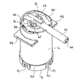
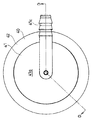
- FIG. 1 is a perspective view of a valve device (first example) according to an embodiment of the present invention.
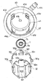
- FIG. 2 is a perspective view showing the outer member and the case constituting the valve device of the first example in a separated state.
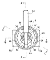
- FIG. 3 is a plan view of the valve device of the first example.
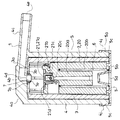
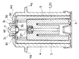
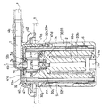
- FIG. 4 is a cross-sectional view taken along the line AA in FIG. 3 and shows a valve open state in which the float valve is in the lowered position.
- FIG. 5 is a cross-sectional view taken along the line BB in FIG. 3 and shows a valve open state in which the float valve is in the lowered position.
- FIG. 6 is a cross-sectional view taken along the line CC in FIG.
- FIG. 3 shows a valve open state in which the float valve is in the lowered position.
- FIG. 7 is a cross-sectional view taken along the line CC in FIG. 3, and shows a closed state in which fuel (not shown) flows into the case and the float valve is raised.
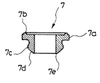
- FIG. 8 is a cross-sectional view of a cylindrical seal body constituting the valve device of the first example.
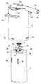
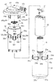
- FIG. 9 is a side view of the valve device (second example) according to the embodiment of the present invention.
- FIG. 10 is a plan view of the valve device of the second example.
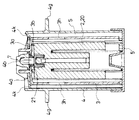
- FIG. 11 is a cross-sectional view taken along the line DD in FIG. 10 and shows a valve open state in which the float valve is in the lowered position.
- FIG. 12 is an exploded perspective view of the valve device of the second example.
- FIG. 13 is a perspective view showing the outer member constituting the valve device of the second example and the inner cylinder constituting the case in a separated state.
- the valve device according to this embodiment is attached to a fuel tank of an automobile, a two-wheeled vehicle, etc., and forms a part of the ventilation passage 1 of the fuel tank, and communicates the inside and outside of the fuel tank in the opened state. Function (see FIGS. 4 and 11).
- the valve device (first example) shown in FIGS. 1 to 8 is provided in a fuel tank using a bracket (not shown) provided in the fuel tank.
- Such a valve device includes a float valve 2, a case 3 for storing the float valve 2, an outer member 4 for storing the case 3, and a cap 5 for closing the lower end of the outer member 4 (see FIG. 4).
- the float valve 2, the case 3, the outer member 4, and the cap 5 are typically made of plastic.
- the case 3 has a top portion 3a and a circular first through hole 3b in the center of the top portion 3a, and has a substantially cylindrical shape with the lower end opened.
- a pair of plate-like projecting portions 3c and 3c projecting upward are formed on the outer side of the top portion 3a (see FIG. 2).
- the pair of plate-like protrusions 3c and 3c are arranged so that their plate surfaces face each other, and the first through hole 3b is formed between the pair of plate-like protrusions 3c and 3c arranged in this way. Yes.
- the outer member 4 has a top portion 4a and a circular second through hole 4b in the center of the top portion 4a, and has a substantially cylindrical shape with the lower end opened (see FIG. 4). ).
- the second through hole 4b extends sideways by connecting one end 4d of the tube integrally with the center of the top portion 4b on the upper surface side of the top portion 4b of the outer member 4, and the other end 4e of the tube. This is communicated to the outside of the tank through a tubular exhaust port 4c which is a connecting portion to one end of a tube (not shown) that forms a part of the tank.
- Engagement holes 3d are formed on both sides of the top portion 4a of the outer member 4 and sandwiching the pipe end 4d of the exhaust port 4c so that the plate-like protrusions 3c can be received with a small gap (FIG. 2). And 5). Further, an attachment portion 4g to the fuel tank side is formed between the top portion 4a and the lower end of the outer member 4 (see FIG. 2).
- the mounting portion 4g has a shape that matches the bracket, and is provided on the left and right sides of the exhaust port 4c. The shape of the mounting portion 4g is appropriately changed according to the shape of the bracket.
- a claw portion 4j is formed on the outer surface of the side portion on the lower end side of the outer member 4.
- the case 3 and the outer member 4 are between the top 3a of the case 3 in which the first through hole 3b is formed and the top 4a of the outer member 4 in which the second through hole 4b is formed.
- a part of the cylindrical seal body 7 which is fitted into the first through hole 3b and communicates with the second through hole 4b inside is sandwiched and combined.
- the cylindrical sealing body 7 is made of rubber or plastic with rubber-like elasticity.
- the cylindrical sealing body 7 has an outer flange portion 7a that forms a circular shape at the upper end of the cylinder (see FIG. 8).
- a circular protrusion 7b is formed on the upper surface of the outer flange portion 7a.
- the outer diameter of the outer flange portion 7a is larger than the hole diameter of the first through hole 3b.
- a circumferential raised portion 7c is formed at the outer peripheral portion of the cylindrical seal body 7 at a position approximately in the middle of the vertical direction.
- An interval corresponding to the thickness of the top portion 3a of the case 3 is formed between the circumferential raised portion 7c and the outer flange portion 7a.
- the cylindrical seal body 7 is fitted into the first through hole 3b from above with the lower end of the cylinder first.
- the outer flange portion 7 a of the cylindrical seal body 7 is in contact with the outer surface of the top portion 3 a of the case 3, and the circumferential bulge portion 7 c is in contact with the inner surface of the top portion 3 a of the case 3.
- the pair of plate-like projecting portions 3c and 3c formed on the top portion 3a of the case 3 are respectively connected to the top portion 4a of the outer member 4.
- the second through hole 4b is positioned immediately above the upper end of the cylindrical seal body 7,
- the outer flange portion 7a of the cylindrical seal body 7 is sandwiched between the outer surface of the top portion 3a of the case 3 and the inner surface of the top portion 4a of the outer member 4 and around the second through hole 4b. That is, in the illustrated example, a part of the cylindrical seal body 7 sandwiched between the case 3 and the outer member 4 is the outer flange portion 7a.
- a state in which a part of the cylindrical seal body 7 is sandwiched that is, a combination state of the case 3 and the outer member 4 is set to one of the case 3 and the outer member 4.
- the engagement claw 3d that is engaged with the engagement hole 3d provided on the other of these is provided to be maintained.
- the engaging claw 3d is provided in the top portion 3a of the case 3, and the engaging hole 3d is provided in the top portion 4a of the outer member 4 (see FIG. 2).
- the engaging claws 3d are formed on the pair of plate-like protrusions 3c and 3c, respectively.
- Each of the pair of plate-like projecting portions 3c and 3c is formed with a split groove 3e, and a part of the plate-like projecting portion 3c divided by this has an upper end as a base that is the center of elastic deformation and a lower end as a free end.
- the engaging claw 3d is formed on the side of the elastic piece 3f that does not face the other plate-like protrusion 3c. Between the base of the elastic piece 3f and the tip of the engaging claw 3d is an inclined surface 3g projecting outward as it goes downward.
- the inner diameter of the outer member 4 is larger than the outer diameter of the case 3, and between the side part of the outer member 4 and the side part of the case 3 combined as described above, the ventilation channel 1 extends over the entire circumference. A gap s forming a part is formed (see FIG. 4).
- the float valve 2 includes a float main body 20 and a valve body 21 provided at an upper portion of the float main body 20 so as to be tiltable.
- the float main body 20 has a cylindrical shape in which the upper end is substantially closed, the annular space 20b is formed around the core portion 20a, and the annular space 20b is opened on the lower end side.
- the upper end of the spring is brought into contact with the inner back portion of the annular space 20b, and the lower end of the spring is brought into contact with the bottom plate 5b of the cap 5 so that the float valve 2 is fixed upward.
- a compression coil spring 6 that constantly applies a force is accommodated.
- the valve body 21 has the following parts (1) to (4) (see FIG. 4). (1) A seal portion 21a that closes the first through hole 3b when the float valve 2 is raised. (2) A catching portion 21b that catches against a part of the float main body 20 and becomes the center of the tilting. (3) A contact portion 21c protruding on the back side of the seal portion 21a (4) A fulcrum portion 21d that comes into contact with the lower end of the cylindrical seal body 7 during the tilting.
- valve body 21 is horizontally moved by the contact of the contact portion 21c by the tilting with the contacted portion 20c formed on the upper portion of the float main body 20. It causes movement in the direction.
- the cap 5 includes a short cylindrical portion 5a having an inner diameter substantially equal to the outer diameter of the lower end of the outer member 4, and a bottom plate 5b that closes the lower end of the short cylindrical portion 5a (see FIG. 1 and FIG. 1). 4).
- the valve device is configured by combining the float valve 2, the case 3, the outer member 4, and the cap 5.
- the lower end of the cylindrical seal body 7 protruding downward from the inner surface of the top portion 3 a of the case 3 becomes the valve seat 7 e of the float valve 2.
- a through portion 4k is provided in the top portion 4a of the outer member 4 (see FIG. 1), and a through portion 3h is provided in a side portion of the case 3 (see FIG. 2). ).
- a plurality of through portions 4 k of the outer member 4 are formed on the outer peripheral portion of the top portion 4 a of the outer member 4.
- the through portion 4k of each outer member 4 has a long hole shape in the circumferential direction of the outer member 4 communicating with the gap s between the outer member 4 and the case 3.
- a plurality of through portions 3 h of the case 3 are formed on the side of the case 3.
- the penetration part 3h of each case 3 has a long hole shape that is long in the vertical direction.
- the inside and outside of the tank are the through part 4k of the outer member 4, the through part 3h of the case 3, the cylindrical seal body 7, and the second through hole 4b, communication is possible through the exhaust port 4c. Since the penetration part 4k of the outer member 4 is formed in the top part 4a, and the penetration part 3h of the case 3 is formed in the side part thereof, the flow path through these penetration parts 3h and 4k is meandering up and down. In the state before the float valve 2 is seated on the valve seat 7e, the outflow of fuel to the outside of the tank is prevented as much as possible.
- the cylinder lower end of the cylindrical seal body 7 facing the case 3 is used as the valve seat 7e, and the float valve 2 uses the valve body 21 provided on the upper part thereof as the valve seat 7e. Is raised to the position where it is seated. As a result, the communication inside and outside the tank is blocked. When the fuel flows out of the case 3, the float valve 2 is lowered again, and the inside and outside of the tank can be communicated again via the valve device.
- the tubular seal body 7 allows the space between the top 4 a of the outer member 4 and the tubular seal body 7 and between the tubular seal body 7 and the case 3. It becomes possible to seal between the part 3a in an airtight state.
- the outer edge portion 7 a of the cylindrical seal body 7 is elastically deformed by the clamping, and the edge portion of the second through hole 4 b of the top portion 4 a of the outer member 4 and the top portion 3 a of the case 3.
- the first through hole 3 b is pressed against the hole edge, and ventilation between the valve device and the outside of the tank is performed only through the inside of the cylindrical seal body 7.
- the cylindrical seal body 7 also serves as the valve seat 7e of the float valve 2.
- the valve device according to this embodiment can form a part having a sealing function by one cylindrical seal body 7, minimizing the number of components of this type of valve device, It contributes to lower prices.
- the valve body 21 brings the contact portion 21c into contact with the contacted portion 20c by the tilting, and the horizontal position of the contacted portion 20c does not change. Moved.
- the cylindrical seal body 7 and the seal portion 21a are made of a material that is easily in close contact, the cylindrical seal body 7 and the seal portion.
- the valve is released from 21a, that is, the valve device is smoothly opened.
- the valve device (second example) shown in FIGS. 9 to 13 is attached to the upper part of the fuel tank T.
- the valve device includes an outer member 40 having a size that closes a mounting hole Ta formed in the upper portion of the fuel tank T, and a case 30 that can be inserted into the fuel tank T through the mounting hole Ta. With the case 30 inserted in the fuel tank T, the outer peripheral portion of the outer member 40 is fixed to the outer surface of the upper portion of the fuel tank T by welding or the like, so that the fuel tank T is provided (FIG. 11). .
- the valve device includes a float valve 2, a case 30 for storing the float valve 2, and an outer member 40 for storing the upper side of the case 30.
- the float valve 2, the case 30, and the outer member 40 are typically made of plastic.
- the case 30 includes an outer cylindrical body 31 and an inner cylindrical body 32 that is combined with the outer cylindrical body 31 by forming a gap S between the outer cylindrical body 31 and the outer cylindrical body 31.
- the outer cylindrical body 31 has a bottom 31a and is provided with a circular through hole 31b in the center of the bottom 31a and has a substantially cylindrical shape with an open upper end (see FIG. 12).
- a plurality of recessed portions 31c, 31c,... Are formed at the upper end portion of the outer cylindrical body 31 at intervals in the direction around the cylindrical axis of the outer cylindrical body 31, and the upper end portion of the outer cylindrical body 31 is It has a crown shape.
- An engagement window 31e is formed in the protruding piece-like portion 31d left between the adjacent recessed portions 31c, 31c of the outer cylindrical body 31.
- the inner cylinder 32 has a top portion 32a and a circular first through hole 32b at the center of the top portion 32a, and has a substantially cylindrical shape with the lower end opened (FIG. 12). reference).
- an engaged part 32c with respect to the engaging part 41d of the outer member 40, a through part 32f, and an engaging projection 32g with respect to the engaging window 31e of the outer cylinder 31 are formed. Has been.
- the engaged portions 32c are provided at four positions with a space between the engaged portions 32c adjacent to each other in the direction around the cylinder axis of the inner cylindrical body 32.
- Each engaged portion 32c has a lower end integrally connected to the outer surface of the inner cylindrical body 32, and a pair of arms 32d and 32d extending upward with a gap between the outer surface and the pair of arms. 32d, and a bridge portion 32e extending between the upper ends of the portions 32d.
- the penetrating portion 32f is a rectangular hole penetrating the inside and outside of the inner cylindrical body 32, and is formed between the adjacent engaged portions 32c and 32c.
- the engaging protrusions 32g protrude from the outer surface of the inner cylindrical body 32, and are respectively provided immediately above the through-holes 32f.
- the outer member 40 has a short cylindrical portion 41 whose upper end is closed and whose lower end is opened, and a flange portion 42 that protrudes outward from the lower end of the short cylindrical portion 41. (Refer to FIG. 12).
- the short cylindrical portion 41 has the upper end, that is, the top portion 41a, and a circular second through hole 41b in the center of the top portion 41a (see FIG. 11).
- the second through hole 41b extends in the lateral direction by integrally connecting one end of the tube to the center of the top portion 41b on the upper surface side of the top portion 41b of the outer member 40, and the other end of the tube is one of the ventilation channels 1. It communicates with the outside of the tank through a tubular exhaust port 41c which is a connecting part to one end of the tubular body P forming the part.
- the lower end of the short cylindrical portion 41 of the outer member 40 is composed of an elastic piece 41e that is integrally connected to the lower end and protrudes downward, and a protrusion 41f formed on the outer side of the lower end of the elastic piece 41e.
- a joint portion 41d is formed.
- the engaging portion 41d is spaced from the engaging portion 41d adjacent to each other in the direction around the cylindrical axis of the short cylindrical portion 41 of the outer member 40 corresponding to the engaged portion 32c. Opened at four places.
- the outer cylindrical body 31 and the inner cylindrical body 32 are arranged from the upper end side of the outer cylindrical body 31 with the lower end of the inner cylindrical body 32 first until the bottom end 31a of the outer cylindrical body 31 abuts the lower end of the inner cylindrical body 32.
- the inner cylinder 32 is inserted into the outer cylinder 31 to be combined.
- each of the projecting piece-like portions 31d is elastically deformed outward by hitting the corresponding engaging protrusion 32g located immediately above the through portion 32f located between the adjacent engaged portions 32c and 32c.
- the inner cylindrical body 32 is elastically restored at the position where the inner cylindrical body 32 is completely inserted, and the engaging projection 32g is received in the window hole 31e and engaged therewith.
- a gap S is formed between the outer cylindrical body 31 and the inner cylindrical body 32 combined in this way so as to go around the cylindrical axis of the case 30. Further, the upper end portion 31f of the outer cylindrical body 31 (the level of the base portion of the projecting piece-shaped portion 31d) is positioned below the upper end of the inner cylindrical body 32 and above the through portion 32f. At the same time, the gap S and the outer side of the case 30 communicate with each other with the upper end portion 31f of the outer cylindrical body 31 as an open end.
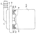
- the case 30 and the outer member 40 configured in this way are formed with a top portion 32a of the inner cylindrical body 32 constituting the case 30 in which the first through hole 32b is formed and the second through hole 41b. Further, between the top portion 41a of the outer member 40, a part of the cylindrical seal body 7 that is fitted into the first through hole 32b and communicates the inside with the second through hole 41b is sandwiched, It comes to be combined.
- the cylindrical seal body 7 is made of rubber or a plastic having rubber-like elasticity as in the first example.
- the cylindrical sealing body 7 has an outer flange portion 7a that forms a circular shape at the upper end of the cylinder (see FIG. 12).
- a circular protrusion 7b is formed on the upper surface of the outer flange portion 7a.
- the outer diameter of the outer flange portion 7a is larger than the diameter of the first through hole 32b.
- a circumferential bulging portion 7c is formed at the outer peripheral portion of the cylindrical seal body 7 at a substantially middle position in the vertical direction (see FIG. 13).
- An interval corresponding to the thickness of the top portion 32a of the inner cylindrical body 32 constituting the case 30 is formed between the circumferential raised portion 7c and the outer flange portion 7a (see FIG. 11). Between the circumferential bulging portion 7c and the cylindrical lower end of the cylindrical seal body 7, there is formed a circumferential inclined surface 7d that decreases the outer diameter of the cylindrical seal body 7 as it approaches the lower end of the cylinder.
- the cylindrical seal body 7 is fitted into the first through hole 32b from above with the lower end side of the cylinder first.
- the outer flange portion 7a of the cylindrical seal body 7 is in contact with the outer surface of the top portion 32a of the inner cylindrical body 32 constituting the case 30 at the position where it is fitted, and the circumferential raised portion 7c is the top portion of the inner cylindrical body 32. It contacts the inner surface of 32a.
- the engaging portions 41d of the outer member 40 are respectively located inside the engaged portions 32c of the inner cylindrical body 32 constituting the case 30.
- the second through hole 41b is located immediately above the upper end of the cylindrical seal body 7.
- the outer flange portion 7a of the cylindrical seal body 7 is formed on the outer surface of the top portion 32a of the inner cylindrical body 32 constituting the case 30 and the inner surface of the top portion 41a of the outer member 40 and around the second through hole 41b. It is pinched. That is, in the illustrated example, a part of the cylindrical seal body 7 sandwiched between the case 30 and the outer member 40 is the outer flange portion 7a.
- the engaging portion 41d is connected to the engaged portion 32c. It is made to maintain by engaging.
- the protrusion 41f hits the bridging portion 32e of the engaged portion 32c, the elastic piece 41e and the arm portion 32d are elastically deformed, and this insertion is allowed, and
- the projection 41f enters under the bridging portion 32e, and the elastic piece 41e and the arm portion 32d are elastically restored and the projection 41f is caught by the bridging portion 32e.
- the combined state of the case 30 and the outer member 40 is maintained (see FIG. 11).
- the float valve 2 and the spring 6 of the second example have substantially the same configuration as the float valve 2 and the spring 6 of the first example, and the outer cylinder 31 and the inner cylinder 32 are combined as described above. Is stored in the inner cylinder 32 prior to.
- the description of the float valve 2 and the spring 6 is omitted in the drawing showing the second example, with the same reference numerals as the symbols given to the float valve 2 and the spring 6 in the drawing showing the first example.
- the valve device is configured by combining the case 30 containing the float valve 2 and the spring 6 with the outer member 40 in this way.
- the lower end of the cylindrical seal body 7 protruding downward from the inner surface of the top portion 32 a of the inner cylindrical body 32 constituting the case 30 becomes the valve seat 7 e of the float valve 2.
- the inside and outside of the tank are the open end of the gap S (the upper end 31 f of the outer cylinder 31) and the inner cylinder 32. Communication is possible through the through portion 32f, the cylindrical seal body 7, the second through hole 41b, and the exhaust port 41c.
- the open end (the upper end portion 31 f of the outer cylinder 31) is positioned above the penetration 32 f of the inner cylinder 32, and the penetration 32 f of the inner cylinder 32 is formed on the side of the inner cylinder 32.
- the flow path through the open end (the upper end portion 31f of the outer cylindrical body 31), the gap S, and the penetration portion 32f is meandering up and down, and the outside of the tank in a state before the float valve 2 is seated on the valve seat 7e.
- the outflow of fuel to the When fuel flows into the case 30 through the through hole 31b of the bottom 31a of the outer cylinder 31, the cylinder lower end of the cylindrical seal body 7 facing the case 30 serves as a valve seat 7e, and the float valve 2
- the valve body 21 provided at the upper part is raised to a position where it is seated on the valve seat 7e. As a result, the communication inside and outside the tank is blocked.
- the float valve 2 is lowered again, and the inside and outside of the tank can be communicated again via the valve device.
- the cylindrical seal body 7 constitutes the top portion 41a of the outer member 40 and the cylindrical seal body 7 and the cylindrical seal body 7 and the case 30. It becomes possible to seal between the top part 32a of the inner side cylinder 32 which carries out an airtight state.
- the cylinder 32 is pressed against the hole edge of the first through hole 32 b of the top 32 a of the cylinder 32, and ventilation between the valve device and the outside of the tank is performed only through the inside of the cylindrical seal body 7.
- the cylindrical seal body 7 also serves as the valve seat 7e of the float valve 2.
- the valve device according to this embodiment can form a part having a sealing function by one cylindrical seal body 7, minimizing the number of components of this type of valve device, It contributes to lower prices.
- the present invention is not limited to the embodiment described above, but includes all embodiments that can achieve the object of the present invention.
Landscapes
- Engineering & Computer Science (AREA)
- General Engineering & Computer Science (AREA)
- Mechanical Engineering (AREA)
- Combustion & Propulsion (AREA)
- Chemical & Material Sciences (AREA)
- Transportation (AREA)
- Life Sciences & Earth Sciences (AREA)
- Sustainable Energy (AREA)
- Sustainable Development (AREA)
- Cooling, Air Intake And Gas Exhaust, And Fuel Tank Arrangements In Propulsion Units (AREA)
- Self-Closing Valves And Venting Or Aerating Valves (AREA)
- Float Valves (AREA)
- Valve Housings (AREA)
Priority Applications (3)
| Application Number | Priority Date | Filing Date | Title |
|---|---|---|---|
| CN201580028959.9A CN106415095B (zh) | 2014-05-09 | 2015-04-24 | 阀装置 |
| EP15789602.8A EP3141785B1 (en) | 2014-05-09 | 2015-04-24 | Valve device |
| US15/309,841 US10113514B2 (en) | 2014-05-09 | 2015-04-24 | Valve device |
Applications Claiming Priority (4)
| Application Number | Priority Date | Filing Date | Title |
|---|---|---|---|
| JP2014097413 | 2014-05-09 | ||
| JP2014-097413 | 2014-05-09 | ||
| JP2015-006043 | 2015-01-15 | ||
| JP2015006043A JP6203205B2 (ja) | 2014-05-09 | 2015-01-15 | 弁装置 |
Publications (1)
| Publication Number | Publication Date |
|---|---|
| WO2015170621A1 true WO2015170621A1 (ja) | 2015-11-12 |
Family
ID=54392474
Family Applications (1)
| Application Number | Title | Priority Date | Filing Date |
|---|---|---|---|
| PCT/JP2015/062584 Ceased WO2015170621A1 (ja) | 2014-05-09 | 2015-04-24 | 弁装置 |
Country Status (5)
| Country | Link |
|---|---|
| US (1) | US10113514B2 (enExample) |
| EP (1) | EP3141785B1 (enExample) |
| JP (1) | JP6203205B2 (enExample) |
| CN (1) | CN106415095B (enExample) |
| WO (1) | WO2015170621A1 (enExample) |
Families Citing this family (8)
| Publication number | Priority date | Publication date | Assignee | Title |
|---|---|---|---|---|
| USD899458S1 (en) * | 2017-02-16 | 2020-10-20 | Eaton Corporation | Fill limit venting valve with high shut-off height |
| JP6908469B2 (ja) * | 2017-08-24 | 2021-07-28 | 株式会社パイオラックス | 弁装置 |
| JP7019515B2 (ja) * | 2018-06-06 | 2022-02-15 | 愛三工業株式会社 | 流体制御弁 |
| WO2020144089A1 (en) * | 2019-01-11 | 2020-07-16 | Eaton Intelligent Power Limited | Flapper assembly, a valve assembly that utilizes the flapper assembly, and a method of forming the flapper assembly |
| EP3924205B1 (en) * | 2019-02-11 | 2024-03-27 | Eaton Intelligent Power Limited | Pressure relief assembly and a valve assembly that uses the pressure relief assembly |
| WO2020164806A1 (en) * | 2019-02-13 | 2020-08-20 | Eaton Intelligent Power Limited | Multi-material orifice plates for vent valve assemblies of liquid containment systems |
| JP7312325B2 (ja) * | 2020-06-15 | 2023-07-20 | 株式会社パイオラックス | 弁装置 |
| JP7442698B2 (ja) * | 2021-02-02 | 2024-03-04 | 株式会社パイオラックス | 弁装置 |
Citations (3)
| Publication number | Priority date | Publication date | Assignee | Title |
|---|---|---|---|---|
| US4886089A (en) * | 1988-05-27 | 1989-12-12 | Gt Development Corporation | Gas venting valve for liquid tank |
| JPH0439061Y2 (enExample) * | 1986-11-27 | 1992-09-11 | ||
| JP2002021667A (ja) * | 2001-05-15 | 2002-01-23 | Nifco Inc | 燃料タンクの液面検知バルブ |
Family Cites Families (16)
| Publication number | Priority date | Publication date | Assignee | Title |
|---|---|---|---|---|
| US5090459A (en) * | 1990-01-29 | 1992-02-25 | Toyoda Gosei Co., Ltd. | Fuel tank system |
| JPH07257205A (ja) * | 1994-03-28 | 1995-10-09 | Toyoda Gosei Co Ltd | 燃料タンク用フロートバルブ |
| JP3131763B2 (ja) | 1995-09-08 | 2001-02-05 | 京三電機株式会社 | 止め弁の構造 |
| US5975116A (en) * | 1996-08-07 | 1999-11-02 | Borg-Warner Automotive, Inc. | Valve having multi-piece valve housing |
| US5960816A (en) | 1997-03-26 | 1999-10-05 | G.T. Products, Inc. | Adjustable length vent valve system for fuel tanks |
| US6634341B2 (en) * | 1999-04-28 | 2003-10-21 | Walbro Corporation | Vent and rollover valve and fuel pump module |
| JP3374120B2 (ja) * | 2000-05-19 | 2003-02-04 | 本田技研工業株式会社 | 燃料タンクのバルブ取付構造 |
| US6578597B2 (en) | 2001-03-08 | 2003-06-17 | Stant Manufacturing Inc. | Fuel tank vent system with liquid fuel filter |
| JP4317397B2 (ja) * | 2003-07-10 | 2009-08-19 | 株式会社パイオラックス | フロート弁装置の製造方法 |
| US6918405B2 (en) | 2003-12-04 | 2005-07-19 | Alfmeier Corporation | Fill limit vent valve |
| US20060000091A1 (en) | 2004-07-02 | 2006-01-05 | Eaton Corporation | Rapid response fuel tank rollover/vent valve |
| JP4742994B2 (ja) * | 2005-09-28 | 2011-08-10 | 豊田合成株式会社 | 燃料遮断弁 |
| JP4939120B2 (ja) * | 2006-06-16 | 2012-05-23 | 株式会社パイオラックス | 液体遮断弁装置 |
| US8186372B2 (en) * | 2007-03-30 | 2012-05-29 | Toyoda Gosei Co., Ltd. | Fuel shut-off valve |
| JP2010188991A (ja) * | 2009-01-23 | 2010-09-02 | Yachiyo Industry Co Ltd | 通気規制弁装置 |
| JP5437784B2 (ja) | 2009-12-17 | 2014-03-12 | 株式会社ニフコ | 燃料タンク用弁装置 |
-
2015
- 2015-01-15 JP JP2015006043A patent/JP6203205B2/ja not_active Expired - Fee Related
- 2015-04-24 WO PCT/JP2015/062584 patent/WO2015170621A1/ja not_active Ceased
- 2015-04-24 US US15/309,841 patent/US10113514B2/en active Active
- 2015-04-24 EP EP15789602.8A patent/EP3141785B1/en active Active
- 2015-04-24 CN CN201580028959.9A patent/CN106415095B/zh active Active
Patent Citations (3)
| Publication number | Priority date | Publication date | Assignee | Title |
|---|---|---|---|---|
| JPH0439061Y2 (enExample) * | 1986-11-27 | 1992-09-11 | ||
| US4886089A (en) * | 1988-05-27 | 1989-12-12 | Gt Development Corporation | Gas venting valve for liquid tank |
| JP2002021667A (ja) * | 2001-05-15 | 2002-01-23 | Nifco Inc | 燃料タンクの液面検知バルブ |
Non-Patent Citations (1)
| Title |
|---|
| See also references of EP3141785A4 * |
Also Published As
| Publication number | Publication date |
|---|---|
| EP3141785B1 (en) | 2024-07-17 |
| CN106415095B (zh) | 2019-08-13 |
| JP2015227723A (ja) | 2015-12-17 |
| CN106415095A (zh) | 2017-02-15 |
| US10113514B2 (en) | 2018-10-30 |
| JP6203205B2 (ja) | 2017-09-27 |
| US20170138316A1 (en) | 2017-05-18 |
| EP3141785A4 (en) | 2018-01-03 |
| EP3141785A1 (en) | 2017-03-15 |
Similar Documents
| Publication | Publication Date | Title |
|---|---|---|
| JP6203205B2 (ja) | 弁装置 | |
| JP6370250B2 (ja) | 弁装置 | |
| JP6203296B2 (ja) | 弁装置 | |
| JP6200097B2 (ja) | 弁ケースの取付構造 | |
| JP4869201B2 (ja) | フロート弁装置 | |
| JP6157404B2 (ja) | 弁装置 | |
| AU2015259182A1 (en) | Mechanically sealed container cap | |
| US7163023B2 (en) | Fuel vapor vent valve float assembly and method of making same | |
| JP2009168045A (ja) | フロート弁装置 | |
| JP6157376B2 (ja) | 弁装置 | |
| JP2019074022A (ja) | 燃料タンク用弁装置 | |
| JP7049483B2 (ja) | 弁装置 | |
| JP2006290085A (ja) | フロートバルブのシール構造 | |
| JP2014144742A (ja) | 燃料タンク用バルブ | |
| WO2015170620A1 (ja) | 弁装置 | |
| JP2015021466A (ja) | バルブ装置 | |
| JP5876731B2 (ja) | 燃料タンク用コネクタ | |
| KR101428932B1 (ko) | 차량용 리어 액슬의 벤트 플러그 | |
| JP2019142462A (ja) | リザーバタンク | |
| JP2006194350A (ja) | 圧力開放弁 | |
| JP2013177108A (ja) | 燃料タンク用弁装置 |
Legal Events
| Date | Code | Title | Description |
|---|---|---|---|
| 121 | Ep: the epo has been informed by wipo that ep was designated in this application |
Ref document number: 15789602 Country of ref document: EP Kind code of ref document: A1 |
|
| NENP | Non-entry into the national phase |
Ref country code: DE |
|
| WWE | Wipo information: entry into national phase |
Ref document number: 15309841 Country of ref document: US |
|
| REEP | Request for entry into the european phase |
Ref document number: 2015789602 Country of ref document: EP |
|
| WWE | Wipo information: entry into national phase |
Ref document number: 2015789602 Country of ref document: EP |