WO2015163459A1 - Appareil d'entraînement de véhicule - Google Patents
Appareil d'entraînement de véhicule Download PDFInfo
- Publication number
- WO2015163459A1 WO2015163459A1 PCT/JP2015/062575 JP2015062575W WO2015163459A1 WO 2015163459 A1 WO2015163459 A1 WO 2015163459A1 JP 2015062575 W JP2015062575 W JP 2015062575W WO 2015163459 A1 WO2015163459 A1 WO 2015163459A1
- Authority
- WO
- WIPO (PCT)
- Prior art keywords
- electrical machine
- control device
- rotating electrical
- flange portion
- drive device
- Prior art date
Links
Images


Classifications
-
- B—PERFORMING OPERATIONS; TRANSPORTING
- B60—VEHICLES IN GENERAL
- B60K—ARRANGEMENT OR MOUNTING OF PROPULSION UNITS OR OF TRANSMISSIONS IN VEHICLES; ARRANGEMENT OR MOUNTING OF PLURAL DIVERSE PRIME-MOVERS IN VEHICLES; AUXILIARY DRIVES FOR VEHICLES; INSTRUMENTATION OR DASHBOARDS FOR VEHICLES; ARRANGEMENTS IN CONNECTION WITH COOLING, AIR INTAKE, GAS EXHAUST OR FUEL SUPPLY OF PROPULSION UNITS IN VEHICLES
- B60K1/00—Arrangement or mounting of electrical propulsion units
- B60K1/04—Arrangement or mounting of electrical propulsion units of the electric storage means for propulsion
-
- B—PERFORMING OPERATIONS; TRANSPORTING
- B60—VEHICLES IN GENERAL
- B60K—ARRANGEMENT OR MOUNTING OF PROPULSION UNITS OR OF TRANSMISSIONS IN VEHICLES; ARRANGEMENT OR MOUNTING OF PLURAL DIVERSE PRIME-MOVERS IN VEHICLES; AUXILIARY DRIVES FOR VEHICLES; INSTRUMENTATION OR DASHBOARDS FOR VEHICLES; ARRANGEMENTS IN CONNECTION WITH COOLING, AIR INTAKE, GAS EXHAUST OR FUEL SUPPLY OF PROPULSION UNITS IN VEHICLES
- B60K6/00—Arrangement or mounting of plural diverse prime-movers for mutual or common propulsion, e.g. hybrid propulsion systems comprising electric motors and internal combustion engines ; Control systems therefor, i.e. systems controlling two or more prime movers, or controlling one of these prime movers and any of the transmission, drive or drive units Informative references: mechanical gearings with secondary electric drive F16H3/72; arrangements for handling mechanical energy structurally associated with the dynamo-electric machine H02K7/00; machines comprising structurally interrelated motor and generator parts H02K51/00; dynamo-electric machines not otherwise provided for in H02K see H02K99/00
- B60K6/20—Arrangement or mounting of plural diverse prime-movers for mutual or common propulsion, e.g. hybrid propulsion systems comprising electric motors and internal combustion engines ; Control systems therefor, i.e. systems controlling two or more prime movers, or controlling one of these prime movers and any of the transmission, drive or drive units Informative references: mechanical gearings with secondary electric drive F16H3/72; arrangements for handling mechanical energy structurally associated with the dynamo-electric machine H02K7/00; machines comprising structurally interrelated motor and generator parts H02K51/00; dynamo-electric machines not otherwise provided for in H02K see H02K99/00 the prime-movers consisting of electric motors and internal combustion engines, e.g. HEVs
- B60K6/22—Arrangement or mounting of plural diverse prime-movers for mutual or common propulsion, e.g. hybrid propulsion systems comprising electric motors and internal combustion engines ; Control systems therefor, i.e. systems controlling two or more prime movers, or controlling one of these prime movers and any of the transmission, drive or drive units Informative references: mechanical gearings with secondary electric drive F16H3/72; arrangements for handling mechanical energy structurally associated with the dynamo-electric machine H02K7/00; machines comprising structurally interrelated motor and generator parts H02K51/00; dynamo-electric machines not otherwise provided for in H02K see H02K99/00 the prime-movers consisting of electric motors and internal combustion engines, e.g. HEVs characterised by apparatus, components or means specially adapted for HEVs
- B60K6/24—Arrangement or mounting of plural diverse prime-movers for mutual or common propulsion, e.g. hybrid propulsion systems comprising electric motors and internal combustion engines ; Control systems therefor, i.e. systems controlling two or more prime movers, or controlling one of these prime movers and any of the transmission, drive or drive units Informative references: mechanical gearings with secondary electric drive F16H3/72; arrangements for handling mechanical energy structurally associated with the dynamo-electric machine H02K7/00; machines comprising structurally interrelated motor and generator parts H02K51/00; dynamo-electric machines not otherwise provided for in H02K see H02K99/00 the prime-movers consisting of electric motors and internal combustion engines, e.g. HEVs characterised by apparatus, components or means specially adapted for HEVs characterised by the combustion engines
-
- B—PERFORMING OPERATIONS; TRANSPORTING
- B60—VEHICLES IN GENERAL
- B60K—ARRANGEMENT OR MOUNTING OF PROPULSION UNITS OR OF TRANSMISSIONS IN VEHICLES; ARRANGEMENT OR MOUNTING OF PLURAL DIVERSE PRIME-MOVERS IN VEHICLES; AUXILIARY DRIVES FOR VEHICLES; INSTRUMENTATION OR DASHBOARDS FOR VEHICLES; ARRANGEMENTS IN CONNECTION WITH COOLING, AIR INTAKE, GAS EXHAUST OR FUEL SUPPLY OF PROPULSION UNITS IN VEHICLES
- B60K6/00—Arrangement or mounting of plural diverse prime-movers for mutual or common propulsion, e.g. hybrid propulsion systems comprising electric motors and internal combustion engines ; Control systems therefor, i.e. systems controlling two or more prime movers, or controlling one of these prime movers and any of the transmission, drive or drive units Informative references: mechanical gearings with secondary electric drive F16H3/72; arrangements for handling mechanical energy structurally associated with the dynamo-electric machine H02K7/00; machines comprising structurally interrelated motor and generator parts H02K51/00; dynamo-electric machines not otherwise provided for in H02K see H02K99/00
- B60K6/20—Arrangement or mounting of plural diverse prime-movers for mutual or common propulsion, e.g. hybrid propulsion systems comprising electric motors and internal combustion engines ; Control systems therefor, i.e. systems controlling two or more prime movers, or controlling one of these prime movers and any of the transmission, drive or drive units Informative references: mechanical gearings with secondary electric drive F16H3/72; arrangements for handling mechanical energy structurally associated with the dynamo-electric machine H02K7/00; machines comprising structurally interrelated motor and generator parts H02K51/00; dynamo-electric machines not otherwise provided for in H02K see H02K99/00 the prime-movers consisting of electric motors and internal combustion engines, e.g. HEVs
- B60K6/22—Arrangement or mounting of plural diverse prime-movers for mutual or common propulsion, e.g. hybrid propulsion systems comprising electric motors and internal combustion engines ; Control systems therefor, i.e. systems controlling two or more prime movers, or controlling one of these prime movers and any of the transmission, drive or drive units Informative references: mechanical gearings with secondary electric drive F16H3/72; arrangements for handling mechanical energy structurally associated with the dynamo-electric machine H02K7/00; machines comprising structurally interrelated motor and generator parts H02K51/00; dynamo-electric machines not otherwise provided for in H02K see H02K99/00 the prime-movers consisting of electric motors and internal combustion engines, e.g. HEVs characterised by apparatus, components or means specially adapted for HEVs
- B60K6/26—Arrangement or mounting of plural diverse prime-movers for mutual or common propulsion, e.g. hybrid propulsion systems comprising electric motors and internal combustion engines ; Control systems therefor, i.e. systems controlling two or more prime movers, or controlling one of these prime movers and any of the transmission, drive or drive units Informative references: mechanical gearings with secondary electric drive F16H3/72; arrangements for handling mechanical energy structurally associated with the dynamo-electric machine H02K7/00; machines comprising structurally interrelated motor and generator parts H02K51/00; dynamo-electric machines not otherwise provided for in H02K see H02K99/00 the prime-movers consisting of electric motors and internal combustion engines, e.g. HEVs characterised by apparatus, components or means specially adapted for HEVs characterised by the motors or the generators
-
- B—PERFORMING OPERATIONS; TRANSPORTING
- B60—VEHICLES IN GENERAL
- B60K—ARRANGEMENT OR MOUNTING OF PROPULSION UNITS OR OF TRANSMISSIONS IN VEHICLES; ARRANGEMENT OR MOUNTING OF PLURAL DIVERSE PRIME-MOVERS IN VEHICLES; AUXILIARY DRIVES FOR VEHICLES; INSTRUMENTATION OR DASHBOARDS FOR VEHICLES; ARRANGEMENTS IN CONNECTION WITH COOLING, AIR INTAKE, GAS EXHAUST OR FUEL SUPPLY OF PROPULSION UNITS IN VEHICLES
- B60K6/00—Arrangement or mounting of plural diverse prime-movers for mutual or common propulsion, e.g. hybrid propulsion systems comprising electric motors and internal combustion engines ; Control systems therefor, i.e. systems controlling two or more prime movers, or controlling one of these prime movers and any of the transmission, drive or drive units Informative references: mechanical gearings with secondary electric drive F16H3/72; arrangements for handling mechanical energy structurally associated with the dynamo-electric machine H02K7/00; machines comprising structurally interrelated motor and generator parts H02K51/00; dynamo-electric machines not otherwise provided for in H02K see H02K99/00
- B60K6/20—Arrangement or mounting of plural diverse prime-movers for mutual or common propulsion, e.g. hybrid propulsion systems comprising electric motors and internal combustion engines ; Control systems therefor, i.e. systems controlling two or more prime movers, or controlling one of these prime movers and any of the transmission, drive or drive units Informative references: mechanical gearings with secondary electric drive F16H3/72; arrangements for handling mechanical energy structurally associated with the dynamo-electric machine H02K7/00; machines comprising structurally interrelated motor and generator parts H02K51/00; dynamo-electric machines not otherwise provided for in H02K see H02K99/00 the prime-movers consisting of electric motors and internal combustion engines, e.g. HEVs
- B60K6/22—Arrangement or mounting of plural diverse prime-movers for mutual or common propulsion, e.g. hybrid propulsion systems comprising electric motors and internal combustion engines ; Control systems therefor, i.e. systems controlling two or more prime movers, or controlling one of these prime movers and any of the transmission, drive or drive units Informative references: mechanical gearings with secondary electric drive F16H3/72; arrangements for handling mechanical energy structurally associated with the dynamo-electric machine H02K7/00; machines comprising structurally interrelated motor and generator parts H02K51/00; dynamo-electric machines not otherwise provided for in H02K see H02K99/00 the prime-movers consisting of electric motors and internal combustion engines, e.g. HEVs characterised by apparatus, components or means specially adapted for HEVs
- B60K6/40—Arrangement or mounting of plural diverse prime-movers for mutual or common propulsion, e.g. hybrid propulsion systems comprising electric motors and internal combustion engines ; Control systems therefor, i.e. systems controlling two or more prime movers, or controlling one of these prime movers and any of the transmission, drive or drive units Informative references: mechanical gearings with secondary electric drive F16H3/72; arrangements for handling mechanical energy structurally associated with the dynamo-electric machine H02K7/00; machines comprising structurally interrelated motor and generator parts H02K51/00; dynamo-electric machines not otherwise provided for in H02K see H02K99/00 the prime-movers consisting of electric motors and internal combustion engines, e.g. HEVs characterised by apparatus, components or means specially adapted for HEVs characterised by the assembly or relative disposition of components
- B60K6/405—Housings
-
- B—PERFORMING OPERATIONS; TRANSPORTING
- B60—VEHICLES IN GENERAL
- B60K—ARRANGEMENT OR MOUNTING OF PROPULSION UNITS OR OF TRANSMISSIONS IN VEHICLES; ARRANGEMENT OR MOUNTING OF PLURAL DIVERSE PRIME-MOVERS IN VEHICLES; AUXILIARY DRIVES FOR VEHICLES; INSTRUMENTATION OR DASHBOARDS FOR VEHICLES; ARRANGEMENTS IN CONNECTION WITH COOLING, AIR INTAKE, GAS EXHAUST OR FUEL SUPPLY OF PROPULSION UNITS IN VEHICLES
- B60K6/00—Arrangement or mounting of plural diverse prime-movers for mutual or common propulsion, e.g. hybrid propulsion systems comprising electric motors and internal combustion engines ; Control systems therefor, i.e. systems controlling two or more prime movers, or controlling one of these prime movers and any of the transmission, drive or drive units Informative references: mechanical gearings with secondary electric drive F16H3/72; arrangements for handling mechanical energy structurally associated with the dynamo-electric machine H02K7/00; machines comprising structurally interrelated motor and generator parts H02K51/00; dynamo-electric machines not otherwise provided for in H02K see H02K99/00
- B60K6/20—Arrangement or mounting of plural diverse prime-movers for mutual or common propulsion, e.g. hybrid propulsion systems comprising electric motors and internal combustion engines ; Control systems therefor, i.e. systems controlling two or more prime movers, or controlling one of these prime movers and any of the transmission, drive or drive units Informative references: mechanical gearings with secondary electric drive F16H3/72; arrangements for handling mechanical energy structurally associated with the dynamo-electric machine H02K7/00; machines comprising structurally interrelated motor and generator parts H02K51/00; dynamo-electric machines not otherwise provided for in H02K see H02K99/00 the prime-movers consisting of electric motors and internal combustion engines, e.g. HEVs
- B60K6/42—Arrangement or mounting of plural diverse prime-movers for mutual or common propulsion, e.g. hybrid propulsion systems comprising electric motors and internal combustion engines ; Control systems therefor, i.e. systems controlling two or more prime movers, or controlling one of these prime movers and any of the transmission, drive or drive units Informative references: mechanical gearings with secondary electric drive F16H3/72; arrangements for handling mechanical energy structurally associated with the dynamo-electric machine H02K7/00; machines comprising structurally interrelated motor and generator parts H02K51/00; dynamo-electric machines not otherwise provided for in H02K see H02K99/00 the prime-movers consisting of electric motors and internal combustion engines, e.g. HEVs characterised by the architecture of the hybrid electric vehicle
- B60K6/48—Parallel type
-
- B—PERFORMING OPERATIONS; TRANSPORTING
- B60—VEHICLES IN GENERAL
- B60L—PROPULSION OF ELECTRICALLY-PROPELLED VEHICLES; SUPPLYING ELECTRIC POWER FOR AUXILIARY EQUIPMENT OF ELECTRICALLY-PROPELLED VEHICLES; ELECTRODYNAMIC BRAKE SYSTEMS FOR VEHICLES IN GENERAL; MAGNETIC SUSPENSION OR LEVITATION FOR VEHICLES; MONITORING OPERATING VARIABLES OF ELECTRICALLY-PROPELLED VEHICLES; ELECTRIC SAFETY DEVICES FOR ELECTRICALLY-PROPELLED VEHICLES
- B60L50/00—Electric propulsion with power supplied within the vehicle
- B60L50/10—Electric propulsion with power supplied within the vehicle using propulsion power supplied by engine-driven generators, e.g. generators driven by combustion engines
- B60L50/16—Electric propulsion with power supplied within the vehicle using propulsion power supplied by engine-driven generators, e.g. generators driven by combustion engines with provision for separate direct mechanical propulsion
-
- H—ELECTRICITY
- H02—GENERATION; CONVERSION OR DISTRIBUTION OF ELECTRIC POWER
- H02K—DYNAMO-ELECTRIC MACHINES
- H02K11/00—Structural association of dynamo-electric machines with electric components or with devices for shielding, monitoring or protection
- H02K11/20—Structural association of dynamo-electric machines with electric components or with devices for shielding, monitoring or protection for measuring, monitoring, testing, protecting or switching
- H02K11/27—Devices for sensing current, or actuated thereby
-
- H—ELECTRICITY
- H02—GENERATION; CONVERSION OR DISTRIBUTION OF ELECTRIC POWER
- H02K—DYNAMO-ELECTRIC MACHINES
- H02K11/00—Structural association of dynamo-electric machines with electric components or with devices for shielding, monitoring or protection
- H02K11/30—Structural association with control circuits or drive circuits
- H02K11/33—Drive circuits, e.g. power electronics
-
- H—ELECTRICITY
- H02—GENERATION; CONVERSION OR DISTRIBUTION OF ELECTRIC POWER
- H02K—DYNAMO-ELECTRIC MACHINES
- H02K5/00—Casings; Enclosures; Supports
- H02K5/04—Casings or enclosures characterised by the shape, form or construction thereof
-
- H—ELECTRICITY
- H02—GENERATION; CONVERSION OR DISTRIBUTION OF ELECTRIC POWER
- H02K—DYNAMO-ELECTRIC MACHINES
- H02K9/00—Arrangements for cooling or ventilating
- H02K9/19—Arrangements for cooling or ventilating for machines with closed casing and closed-circuit cooling using a liquid cooling medium, e.g. oil
-
- B—PERFORMING OPERATIONS; TRANSPORTING
- B60—VEHICLES IN GENERAL
- B60K—ARRANGEMENT OR MOUNTING OF PROPULSION UNITS OR OF TRANSMISSIONS IN VEHICLES; ARRANGEMENT OR MOUNTING OF PLURAL DIVERSE PRIME-MOVERS IN VEHICLES; AUXILIARY DRIVES FOR VEHICLES; INSTRUMENTATION OR DASHBOARDS FOR VEHICLES; ARRANGEMENTS IN CONNECTION WITH COOLING, AIR INTAKE, GAS EXHAUST OR FUEL SUPPLY OF PROPULSION UNITS IN VEHICLES
- B60K6/00—Arrangement or mounting of plural diverse prime-movers for mutual or common propulsion, e.g. hybrid propulsion systems comprising electric motors and internal combustion engines ; Control systems therefor, i.e. systems controlling two or more prime movers, or controlling one of these prime movers and any of the transmission, drive or drive units Informative references: mechanical gearings with secondary electric drive F16H3/72; arrangements for handling mechanical energy structurally associated with the dynamo-electric machine H02K7/00; machines comprising structurally interrelated motor and generator parts H02K51/00; dynamo-electric machines not otherwise provided for in H02K see H02K99/00
- B60K6/20—Arrangement or mounting of plural diverse prime-movers for mutual or common propulsion, e.g. hybrid propulsion systems comprising electric motors and internal combustion engines ; Control systems therefor, i.e. systems controlling two or more prime movers, or controlling one of these prime movers and any of the transmission, drive or drive units Informative references: mechanical gearings with secondary electric drive F16H3/72; arrangements for handling mechanical energy structurally associated with the dynamo-electric machine H02K7/00; machines comprising structurally interrelated motor and generator parts H02K51/00; dynamo-electric machines not otherwise provided for in H02K see H02K99/00 the prime-movers consisting of electric motors and internal combustion engines, e.g. HEVs
- B60K6/42—Arrangement or mounting of plural diverse prime-movers for mutual or common propulsion, e.g. hybrid propulsion systems comprising electric motors and internal combustion engines ; Control systems therefor, i.e. systems controlling two or more prime movers, or controlling one of these prime movers and any of the transmission, drive or drive units Informative references: mechanical gearings with secondary electric drive F16H3/72; arrangements for handling mechanical energy structurally associated with the dynamo-electric machine H02K7/00; machines comprising structurally interrelated motor and generator parts H02K51/00; dynamo-electric machines not otherwise provided for in H02K see H02K99/00 the prime-movers consisting of electric motors and internal combustion engines, e.g. HEVs characterised by the architecture of the hybrid electric vehicle
- B60K6/48—Parallel type
- B60K2006/4825—Electric machine connected or connectable to gearbox input shaft
-
- B—PERFORMING OPERATIONS; TRANSPORTING
- B60—VEHICLES IN GENERAL
- B60Y—INDEXING SCHEME RELATING TO ASPECTS CROSS-CUTTING VEHICLE TECHNOLOGY
- B60Y2200/00—Type of vehicle
- B60Y2200/90—Vehicles comprising electric prime movers
- B60Y2200/92—Hybrid vehicles
-
- B—PERFORMING OPERATIONS; TRANSPORTING
- B60—VEHICLES IN GENERAL
- B60Y—INDEXING SCHEME RELATING TO ASPECTS CROSS-CUTTING VEHICLE TECHNOLOGY
- B60Y2400/00—Special features of vehicle units
- B60Y2400/11—Electric energy storages
- B60Y2400/112—Batteries
-
- Y—GENERAL TAGGING OF NEW TECHNOLOGICAL DEVELOPMENTS; GENERAL TAGGING OF CROSS-SECTIONAL TECHNOLOGIES SPANNING OVER SEVERAL SECTIONS OF THE IPC; TECHNICAL SUBJECTS COVERED BY FORMER USPC CROSS-REFERENCE ART COLLECTIONS [XRACs] AND DIGESTS
- Y02—TECHNOLOGIES OR APPLICATIONS FOR MITIGATION OR ADAPTATION AGAINST CLIMATE CHANGE
- Y02T—CLIMATE CHANGE MITIGATION TECHNOLOGIES RELATED TO TRANSPORTATION
- Y02T10/00—Road transport of goods or passengers
- Y02T10/60—Other road transportation technologies with climate change mitigation effect
- Y02T10/62—Hybrid vehicles
Definitions
- the present invention relates to a vehicle drive device that includes a rotating electrical machine that serves as a driving force source for wheels together with an internal combustion engine, and a transmission that is arranged alongside the rotating electrical machine.
- Hybrid vehicles equipped with different types of power for example, an internal combustion engine and a rotating electric machine, have been put into practical use as a driving force source for wheels.
- a large amount of mounting space is required as compared with, for example, a case where only the internal combustion engine is used as a driving force source. For this reason, it is important to efficiently mount parts constituting a plurality of driving force sources to save space.
- Patent Document 1 discloses a vehicle drive device for a hybrid vehicle.
- the case (101) of the drive device (20) is configured to be divided into two cases (102, 104).
- the two cases (102, 104) that can be divided are respectively formed with flanges (105, 106), and these flanges (105, 106) are brought into contact with each other and fixed with bolts or the like. 101) are integrated.
- One case (102) is provided with an opening (108) when viewed from one direction along the contact surfaces of the flanges (viewed from above in the perspective view of FIG. 3 of Patent Document 1).
- a power control unit such as a power element substrate (120) is attached and covered with a cover (150).
- the power element substrate (120) is arranged on one case (102) side with respect to the contact surfaces of the flanges.
- the power element substrate (120) is arranged so as not to protrude from the outer shape of the drive device (20) when viewed from one direction along the contact surfaces of the flanges (see the drive device (20) from the side). Then, it is necessary to fit the size (width) of the power element substrate (120) within the length from the flange to the end of one case (102), that is, the width of the case (102).
- the vehicle drive device is, as one aspect, A rotating electrical machine that serves as a driving force source for the wheels together with the internal combustion engine; A transmission that is arranged alongside the rotating electrical machine in an axial direction that is an extending direction of the rotational axis of the rotating electrical machine; A drive device case configured by combining a first case portion that houses the rotating electrical machine and a second case portion that houses the transmission.
- the first case portion has a first opening end portion that is an end portion that opens toward an axial first direction side that is one side of the axial direction, and the axial direction around the first opening end portion.
- a first flange portion having an enlarged diameter on the outside in the radial direction orthogonal to The second case portion has a second opening end portion that is an end portion that opens toward the axial second direction side, which is the other side of the axial direction, and the radial direction around the second opening end portion.
- a second flange portion having an enlarged diameter outside The vehicle drive device in which the first flange portion and the second flange portion are fastened by a fastening member to form a coupling flange portion, Furthermore, the control device for controlling the rotating electrical machine, comprising a rotating electrical machine control device fixed to the outside of either the first case portion and the second case portion, The rotating electrical machine control device has a wide part and a narrow part whose length along the axial direction is shorter than the wide part, The narrow part and the wide part overlap each other when viewed in the specific radial direction, which is the specific radial direction, and the narrow part is disposed so as to be located on the inner side in the radial direction than the wide part.
- the narrow part is arranged so as not to overlap in the specific radial direction with respect to the coupling flange part, and to overlap in the axial direction,
- the wide part is arranged so as to overlap with the coupling flange portion when viewed in the specific radial direction and not overlap when viewed in the axial direction.
- the “specific radial direction” refers to a specific direction that falls within a certain angular range among radial directions that can rotate 360 degrees around the axial direction.
- the vehicle drive device is defined based on the vertical direction, the vehicle width direction, the front-rear direction, and the like in a state where the vehicle drive device is mounted on the vehicle.
- overlap means that at least a part of two members appear to overlap each other when viewed from a specified line-of-sight direction.
- the rotating electrical machine control device is prevented from protruding from the outer shape of the vehicle drive device in the axial direction.
- the size in the radial direction can be suppressed. That is, the relatively wide-width parts in the axial direction overlap with the coupling flange portion when viewed in the specific radial direction, so that the coupling flange portion and the wide-width parts do not line up in the axial direction.
- the axial length can be suppressed.
- the drive device of the hybrid vehicle comprised by several components can be comprised in space saving.
- FIG. 3 is a conceptual diagram schematically showing an example of an arrangement relationship between a coupling flange portion, a wide part, and a narrow part in the form shown in FIGS.
- FIG. 6 is a conceptual diagram schematically showing an example of an arrangement relationship among the coupling flange portion, the wide part, and the narrow part in the form shown in FIGS.
- Conceptual diagram schematically showing another example of the arrangement relationship between the coupling flange, the wide part, and the narrow part Conceptual diagram schematically showing still another example of the arrangement relationship between the coupling flange portion, the wide part, and the narrow part
- a vehicle drive device in a vehicle (hybrid vehicle) provided with both the internal combustion engine E and the rotating electrical machine MG as a drive force source for the wheels W of the vehicle.
- the internal combustion engine E is an internal combustion engine that outputs power by explosion combustion of hydrocarbon fuels such as gasoline, light oil, ethanol, natural gas, and hydrogen.
- the rotating electrical machine MG is a rotating electrical machine that operates by multi-phase alternating current (here, three-phase alternating current), and can function as both an electric motor and a generator.
- the drive device 1 (vehicle drive device) includes at least a rotating electrical machine MG that serves as a driving force source for the wheels W together with the internal combustion engine E, and a transmission device TM.
- the output from the transmission TM is transmitted to the wheels W via a counter gear (not shown) and a differential gear DF.
- the speed change device TM is arranged side by side with the rotary electric machine MG in the axial direction X, which is the extending direction of the rotation axis of the rotary electric machine MG.
- the axial direction X and the radial direction Y are defined with reference to the rotational axis of the rotating electrical machine MG.
- FIG. 2 illustrates a rotating electrical machine control device 70 that drives and controls the rotating electrical machine MG.
- the rotating electrical machine control device 70 is configured to include an inverter 71 (power converter), and the inverter 71 converts power between DC power supplied from a DC power source 74 and AC power.
- the power supply voltage of the DC power supply 74 is, for example, 200 to 400 [V].
- the DC power source 74 is a secondary battery (battery) such as a nickel metal hydride battery or a lithium ion battery, or an electric double layer capacitor.
- DC power supply 74 can supply electric power to rotating electric machine MG via inverter 71 and can store electric power obtained by electric power generation by rotating electric machine MG.
- a smoothing capacitor for smoothing the voltage between the positive and negative electrodes (DC link voltage Vdc) on the DC side of the inverter 71 is provided.
- the DC link capacitor 76 stabilizes a DC voltage (DC link voltage Vdc) that fluctuates according to fluctuations in power consumption of the rotating electrical machine MG.
- the inverter 71 converts the DC power having the DC link voltage Vdc into a plurality of phases (n is a natural number, n-phase, here, three phases) AC power and supplies the AC power to the rotating electrical machine MG, and the AC generated by the rotating electrical machine MG. The power is converted to DC power and supplied to the DC power supply.
- the inverter 71 includes a plurality of switching elements.
- Switching elements include IGBT (Insulated Gate Bipolar Transistor), Power MOSFET (Metal Oxide Semiconductor Semiconductor Field Field Effect Transistor), SiC-MOSFET (Silicon Carbon Metal Metal Oxide Semiconductor Semiconductor FET), SiC-SIT (SiC Power Induction Power Transistor, etc.) It is preferable to apply a semiconductor element. As shown in FIG. 2, in this embodiment, an IGBT 73 is used as a switching element.
- the inverter 71 is configured by a bridge circuit having a number of arms corresponding to each of a plurality of phases. That is, as shown in FIG. 2, two IGBTs 73 are arranged between the DC positive side of the inverter 71 (positive power supply line P on the positive side of the DC power supply) and the DC negative side (negative power supply line N on the negative side of the DC power supply). Are connected in series to form one arm. In the case of three-phase alternating current, this series circuit (one arm) is connected in parallel with three lines (three phases).
- each IGBT 73 is provided with a free wheel diode (FWD) 75 in parallel with the direction from the negative electrode “N” to the positive electrode “P” (the direction from the lower side to the upper side) as the forward direction.
- the inverter 71 of the three-phase arm comprised including IGBT73 and the freewheel diode 75 has illustrated the form modularized in one package as IPM (Intelligent
- the inverter 71 is controlled by the inverter control device 40.
- the inverter control device 40 is constructed using a logic circuit such as a microcomputer as a core member.
- the inverter control device 40 uses a vector control method based on the target torque of the rotating electrical machine MG provided as a request signal from another control device such as the vehicle ECU 90 via a CAN (Controller Area Network) or the like.
- Current feedback control is performed to control the rotating electrical machine MG via the inverter 71.
- the inverter control device 40 includes various functional units for current feedback control, and each functional unit is realized by cooperation of hardware such as a microcomputer and software (program). . Since the current feedback control is known, a detailed description thereof is omitted here.
- the actual current flowing through the coils 78 of each phase of the rotating electrical machine MG is detected by the current sensor 77, and the inverter control device 40 acquires the detection result. Since the three-phase alternating current is balanced and the instantaneous value is always zero (center of amplitude), only two of the three phases may be detected, and the remaining one phase may be obtained by calculation. Further, the magnetic pole position and the rotational speed at each point of time of the rotor of the rotating electrical machine MG are detected by a rotation sensor (not shown) such as a resolver, or by calculation using the magnetic saliency of the rotor of the rotating electrical machine MG. (Sensorless magnetic pole position detection).
- the rotating electrical machine MG when the rotating electrical machine MG is rotating, magnetic pole position information is included in the induced electromotive force. Therefore, the induced electromotive force is estimated from the output voltage of the inverter 71 and the feedback current, and the rotation speed and the magnetic pole position are estimated. On the other hand, since the induced electromotive force does not occur or is very small when the rotating electrical machine is stopped or rotating at a low speed, a high-frequency observation signal (observation current or observation voltage) that is an electrical stimulus is used. Applied to the rotating electrical machine MG, the rotational speed and magnetic pole position are estimated from the response.
- the rotating electrical machine MG, the transmission device TM, and the rotating electrical machine control device 70 are integrated with the drive device 1.
- the driving device 1 includes a driving device case 10 configured by combining a first case portion 11 that accommodates the rotating electrical machine MG and a second case portion 12 that accommodates the transmission device TM. I have.
- the first case portion 11 has a first opening end portion 11t that is an end portion that opens toward the first axial direction X1 side that is one side in the axial direction X. Further, the first case portion 11 has a first flange portion 11f whose diameter is increased outside the radial direction Y (radially outward Y2) perpendicular to the axial direction X around the first opening end portion 11t. .
- the 2nd case part 12 has the 2nd opening edge part 12t which is an edge part opened toward the axial 2nd direction side X2 which is the other side of the axial direction X.
- the second case portion 12 has a second flange portion 12f that is expanded outward in the radial direction Y around the second opening end portion 12t.
- 1st case part 11 and 2nd case part 12 contact 1st flange part 11f and 2nd flange part 12f, and are fixed by a fastening member, and constitute drive device case 10.
- the first flange portion 11 f and the second flange portion 12 f are fastened by a fastening member to form a coupling flange portion 15 in the drive device case 10.
- the rotating electrical machine control device 70 is fixed to the outside of either the first case part 11 or the second case part 12 (target case part).
- the control device case portion 13 in which the rotating electrical machine control device 70 is accommodated is attached outside the target case portion, and the control device cover 18 is attached to the control device case portion 13. That is, the components of the driving device 1 are contained in a space formed by the first case portion 11, the second case portion 12, the control device case portion 13, and the control device cover 18.
- the rotating electrical machine control device 70 includes an inverter control board 20 on which electronic components constituting the inverter control apparatus 40 are mounted, a board bracket 21 that fixes the inverter control board 20, and an IPM 22. (Switching element module), power supply module 23 including DC link capacitor 76, inverter bus bar module 24, current sensor 77, EOP (electric oil pump) bus bar module 26, EOP driver chip 27, EOP control board 28 Yes. These components are accommodated in the control device case section 13 and fixed to the drive device case 10. As shown in FIG. 5, the control device case portion 13 is formed with a cooling device 25 having a plurality of fins.
- the cooling device 25 exemplifies a water cooling type using cooling water or the like.
- the cooling device 25 is installed so that at least the IPM 22 can be cooled, and the IPM 22 and the cooling device 25 are arranged in contact with each other.
- the power supply module 23 is supplied from a power supply wiring for connecting the DC power supply 74 (high-voltage DC power supply) and the inverter 71, and a low-voltage DC power supply (not shown) for supplying power of about 12 [V] to the inverter control device 40. Power supply wiring and the like are also included.
- an EOP control device 41 (electric pump control device) that controls a pump electric motor (not shown) as a driving force source of a hydraulic pump (not shown) is integrated with the drive device 1.
- the form which has been illustrated is illustrated.
- the above-described EOP bus bar module 26, EOP driver chip 27, and EOP control board 28 correspond to the EOP control device 41 (electric pump control device).
- the EOP driver chip 27 is integrated with a circuit including a switching element for driving and controlling the pump motor.
- the parts constituting the rotating electrical machine control device 70 include a wide part 3 having a relatively long length along the axial direction X and a narrow part 5 having a relatively short length. is there. That is, the wide part 3 is a part whose length along the axial direction X is longer than that of the narrow part 5, and the narrow part 5 is a part whose length along the axial direction X is shorter than that of the wide part 3. is there.
- the IPM 22 is the wide-width component 3
- the EOP control device 41 including the EOP driver chip 27 and the EOP control board 28 is the narrow-width component 5.
- the narrow part 5 (EOP driver chip 27, EOP control board 28) and the wide part 3 (IPM 22) are such that the narrow part 5 is in the radial direction Y more than the wide part 3. It arrange
- the specific radial direction YS is a vertical direction in FIGS. 3 and 5 and a direction orthogonal to the paper surface in FIG.
- the radial direction Y can be rotated 360 degrees about the axial direction X, for example, the vertical direction in the state where the drive device 1 is installed in the vehicle (the vertical direction in FIGS. 3 and 5 and perpendicular to the paper surface in FIG. 4).
- Direction is defined as a specific radial direction YS.
- the narrow-width parts 5 (EOP driver chip 27, EOP control board 28) are arranged so as not to overlap in the specific radial direction YS but to overlap in the axial direction X with respect to the coupling flange portion 15. ing. Further, the wide part 3 (IPM 22) is arranged so as to overlap with the coupling flange portion 15 when viewed in the specific radial direction YS and not when viewed in the axial direction X.
- the rotary electric machine control device 70 is arranged.
- the size in the radial direction Y can be suppressed while suppressing the projection from the outer shape of the drive device 1 in the axial direction X. That is, the wide part 3 that is relatively long in the axial direction X overlaps with the coupling flange part 15 when viewed in the specific radial direction YS, so that the coupling flange part 15 and the wide part 3 do not line up in the axial direction X.
- the overall axial length of the drive device 1 can be suppressed.
- the narrow part 5 having a relatively short axial length overlaps with the coupling flange part 15 when viewed in the axial direction X, the coupling flange part 15 and the narrow part in the radial direction Y (specific radial direction YS). 5 can no longer be arranged, and the overall radial size of the drive device 1 can be suppressed.
- the rotating electrical machine control device 70 is accommodated in the control device case portion 13, and the control device case portion 13 is one of the first case portion 11 and the second case portion 12. It is attached to the outside of the case part.
- the control device case portion 13 is fixed to the outside of the second case portion 12 as the target case portion.
- an attachment seat 14 for attaching the control device case part 13 is formed so as to protrude outward.
- the wide part 3 (for example, IPM 22) among the parts constituting the rotating electrical machine control device 70 overlaps with the coupling flange portion 15 when viewed in the specific radial direction YS.
- the mounting seat 14 is formed on the coupling flange portion 15. That is, when the part of the mounting seat 14 is integrally formed on the radially outer side Y2 of the target flange portion that is the flange portion of the target case portion among the first flange portion 11f and the second flange portion 12f. Is preferred. Since the first flange portion 11f and the second flange portion 12f are fixed to each other to form the coupling flange portion 15, the first flange portion 11f and the second flange portion 12f are different from the target case portion. This does not impede a configuration in which the flange portion of the case portion is the target flange portion, and a part of the mounting seat 14 is integrally formed on the radially outer side Y2 of the target flange portion.
- the width of the narrow part 5 is reduced in the direction opposite to the coupling flange portion 15 along the axial direction X.
- an empty space is generated in the radial inner side Y1 of the wide part 3 along the specific radial direction YS.
- a current sensor 77 is arranged in a space on the left side of the EOP driver chip 27 and below the IPM 22.
- the coil 78 included in the rotating electrical machine MG is located at the position overlapping with the coupling flange portion 15 when viewed in the axial direction X and on the opposite side of the coupling flange portion 15 with the narrow-width component 5 (EOP driver chip 27) interposed therebetween.
- a current sensor 77 for detecting a current flowing through the (stator coil) is disposed.
- the inverter bus bar module 24 is connected to the IPM 22 that is the wide component 3 on the side opposite to the coupling flange portion 15 along the axial direction X.
- the current sensor 77 detects a current flowing through the bus bar connected to the coil 78 among the bus bars constituting the inverter bus bar module 24. Therefore, it is preferable that the current sensor 77 is disposed on the opposite side of the connecting flange portion 15 along the axial direction X in which the inverter bus bar module 24 is disposed. With such an arrangement, the space can be used effectively, and the drive device 1 can be prevented from being enlarged.
- the form of the driving device 1 is not limited to the form described above with reference to FIGS.
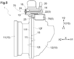
- an exploded perspective view of the drive device 1 (FIG. 6), a top view of the drive device 1 (FIG. 7), and VIII-VIII in FIG. This will be described with reference to a sectional view (FIG. 8).
- the same reference numerals as in FIGS. 3 to 5 are used for common members.
- the drive device 1 includes a drive device case 10 configured by combining a first case portion 11 that houses the rotating electrical machine MG and a second case portion 12 that houses the transmission TM. .
- the first case portion 11 is a first opening end that is an end portion that opens toward the axial first direction X ⁇ b> 1 side, which is one side of the axial direction X. Part 11t. Further, the first case portion 11 has a first flange portion 11f whose diameter is increased outside the radial direction Y (radially outer side Y2) perpendicular to the axial direction X around the first opening end portion 11t.
- the 2nd case part 12 has the 2nd opening edge part 12t which is an edge part opened toward the axial 2nd direction side X2 which is the other side of the axial direction X.
- the second case portion 12 has a second flange portion 12f that is expanded outward in the radial direction Y around the second opening end portion 12t.
- 1st case part 11 and 2nd case part 12 contact 1st flange part 11f and 2nd flange part 12f, and are fixed by a fastening member, and constitute drive device case 10.
- the first flange portion 11 f and the second flange portion 12 f form a coupling flange portion 15 in the drive device case 10.
- the rotating electrical machine control device 70 is fixed to the outside of either the first case part 11 or the second case part 12 (target case part).
- the control device case portion 13 in which the rotating electrical machine control device 70 is accommodated is attached to the outside of the target case portion, and the control device cover 18 is attached to the control device case portion 13. That is, the components of the driving device 1 are contained in a space formed by the first case portion 11, the second case portion 12, the control device case portion 13, and the control device cover 18.
- the rotating electrical machine control device 70 includes an inverter control board 20 on which electronic components constituting the inverter control device 40 are mounted, an IPM 22 (switching element module), a DC link capacitor 76, an inverter. Bus bar module 24, current sensor 77, and EOP (electric oil pump) driver chip 27.
- the inverter control board 20 includes an EOP control circuit (EOP control device 41). These components are accommodated in the control device case section 13 and fixed to the drive device case 10. Also in this embodiment, as shown in FIG. 8, the control device case portion 13 is formed with a cooling device 25 having a plurality of fins.
- the cooling device 25 is a water-cooling type using cooling water or the like, and reference numeral 29 in FIGS. 6 and 8 is an input / output port for the refrigerant. Also in this embodiment, the cooling device 25 is installed so that at least the IPM 22 can be cooled, and the IPM 22 and the cooling device 25 are arranged to contact each other.
- the components constituting the rotating electrical machine control device 70 include the wide part 3 having a relatively long length along the axial direction X and the relatively short narrow part as shown in FIGS. There is a width part 5.
- the IPM 22 is the wide part 3
- the DC link capacitor 76 is the narrow part 5.
- the narrow-width component 5 (DC link capacitor 76) and the wide-width component 3 (IPM 22) are arranged such that the narrow-width component 5 is located on the inner side in the radial direction Y (the radially inner side). Y1). Further, the narrow part 5 (DC link capacitor 76) and the wide part 3 (IPM 22) are arranged so as to overlap each other when viewed in a specific direction (specific radial direction YS) in the radial direction Y. .
- the specific radial direction YS is a vertical direction in FIGS. 6 and 8 and a direction orthogonal to the paper surface in FIG.
- the radial direction Y can be rotated 360 degrees about the axial direction X, for example, the vertical direction in the state where the drive device 1 is installed in the vehicle (the vertical direction in FIGS. 6 and 8 and orthogonal to the paper surface in FIG. 7)
- the direction along the direction) is defined as a specific radial direction YS.
- the narrow-width component 5 (DC link capacitor 76) is arranged so as to overlap with the coupling flange portion 15 when viewed in the axial direction X and not when viewed in the specific radial direction YS.
- the wide part 3 (IPM 22) is arranged so as to overlap with the coupling flange portion 15 when viewed in the specific radial direction YS and not when viewed in the axial direction X.
- the wide part 3 (IPM 22) and the narrow part 5 (DC link capacitor 76) among the parts constituting the rotating electrical machine control device 70 in this manner.
- the overall axial length of the drive device 1 can be suppressed.
- the narrow part 5 having a relatively short axial length overlaps with the coupling flange part 15 when viewed in the axial direction X, the coupling flange part 15 and the narrow part in the radial direction Y (specific radial direction YS). 5 can no longer be arranged, and the overall radial size of the drive device 1 can be suppressed.
- the narrow-width component 5 and the wide-width component 3 in the drive device 1 are as follows. Has been placed. First, the narrow-width component 5 and the wide-width component 3 overlap each other when viewed in the specific radial direction YS, which is the specific radial direction Y, and the narrow-width component 5 is more radially inner than the wide-width component 3 (in the radial direction). It arrange
- the narrow-width part 5 is arranged so as not to overlap the coupling flange portion 15 when viewed in the specific radial direction YS, but overlaps when viewed in the axial direction X. Thus, they are arranged so as to overlap in the specific radial direction YS and not to overlap in the axial direction X. 3 to 5, the IPM 22 corresponds to the wide-width component 3, and the EOP control device 41 (EOP driver chip 27 and EOP control board 28) corresponds to the narrow-width component 5.
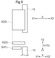
- FIG. 9 is a conceptual diagram schematically showing the relationship between the coupling flange portion 15, the IPM 22, the EOP driver chip 27, and the EOP control device 41.
- the upper stage in FIG. 9 is a top view corresponding to FIG. 4, and the lower stage is a cross-sectional view (side view) corresponding to FIG.
- the relative positional relationship between the wide component 3 and the narrow component 5, the positional relationship between the coupling flange 15 and the wide component 3, and the positional relationship between the coupling flange 15 and the narrow component 5 satisfy the above-mentioned regulations. If so, the wide part 3 and the narrow part 5 may be made to correspond to other parts as illustrated in FIGS.
- FIG. 9 is a conceptual diagram schematically showing the relationship between the coupling flange portion 15, the IPM 22, and the DC link capacitor 76 as in FIG. 9. However, in FIG. It is shown in a state rotated 180 degrees.
- the wide-width part 3 and the narrow-width part 5 may correspond to other parts.
- An example is shown in FIGS. Also in FIG.11 and FIG.12, the upper stage is a top view and the lower stage is sectional drawing (side view).
- the wide part 3 is an IPM 22 and an EOP control device 41 (electric pump control device).
- the narrow-width parts 5 are the cooling device 25 and the DC link capacitor 76.
- the EOP control device 41 which is the narrow-width component 5 in the embodiment illustrated in FIGS. 3 to 5 and FIG. 9, is arranged side by side with the IPM 22, and constitutes the wide-width component 3 together. Since the cooling device 25 can cool the IPM 22 even if it does not contact the entire surface of the IPM 22, the cooling device 25 is configured as the narrow part 5 having a shorter length in the axial direction X than the IPM 22 that is the wide part 3.
- the cooling device 25 is arranged such that the main part of the IPM 22 (a place where a switching element is present and a large amount of heat is generated) and the cooling device 25 are in contact with each other.
- the wide part 3 is a DC link capacitor 76
- the narrow part 5 is an IPM 22, an EOP control device 41 (electric pump control device), and a cooling device 25.
- the EOP control device 41 is arranged side by side with the IPM 22, and in this example, both form the narrow-width component 5.
- the cooling device 25 is disposed in contact with the IPM 22.
- the cooling device 25 is disposed so as to contact the IPM 22 and the EOP control device 41.
- the hybrid vehicle drive device 1 composed of a plurality of components can be configured in a space-saving manner.
- the switching element constituting the inverter 71 is illustrated as a module that is modularized as the IPM 22. However, even if the inverter 71 is configured by mounting individual components such as IGBTs on a wiring board. Good.
- the electric pump control device EOP control device 41
- the drive device 1 includes a control device (rotary electric machine) for driving and controlling the rotary electric machine MG. Only the control device 70) may be incorporated.
- the vehicle drive device (1) in the embodiment described above includes at least the following configuration. Specifically, together with the internal combustion engine (E), a rotating electrical machine (MG) serving as a driving force source for the wheels (W), A transmission (TM) disposed alongside the rotating electrical machine (MG) in the axial direction (X), which is an extending direction of the rotational axis of the rotating electrical machine (MG); A driving device case (10) configured by combining a first case portion (11) that accommodates the rotating electrical machine (MG) and a second case portion (12) that accommodates the transmission (TM); Prepared,
- the first case portion (11) has a first opening end portion (11t) that is an end portion that opens toward an axial first direction (X1) side that is one side of the axial direction (X), and A first flange portion (11f) having a diameter expanded outside (Y2) in a radial direction (Y) perpendicular to the axial direction (X) around the first opening end portion (11t);
- the vehicle drive device (1) wherein the first flange portion (11f) and the second flange portion (12f) are fastened by a fastening member (19) to form a coupling flange portion (15).
- the rotating electrical machine control device (70) includes a wide part (3) and a narrow part (5) whose length along the axial direction (X) is shorter than the wide part (3).
- the narrow part (5) and the wide part (3) overlap each other in the specific radial direction (YS), which is the specific radial direction (Y), and the narrow part (5) It is arranged so as to be located on the inner side (Y1) in the radial direction (Y) than the wide part (3),
- the narrow-width component (5) is arranged so as not to overlap with the coupling flange portion (15) in the specific radial direction (YS) but to overlap in the axial direction (X),
- the wide part (3) is arranged so as to overlap with the coupling flange part (15) in the specific radial direction (YS) and not overlap in the axial direction (X).
- the rotary electric machine control device (70) is moved in the axial direction (X).
- the size in the radial direction (Y) can be suppressed while suppressing the protrusion from the outer shape of the vehicle drive device (1). That is, the wide part (3) which is relatively long in the axial direction (X) overlaps with the coupling flange portion (15) when viewed in the specific radial direction (YS), so that the coupling flange in the axial direction (X).
- the part (15) and the wide part (3) are not lined up, and the overall axial length of the vehicle drive device (1) can be suppressed.
- the narrow part (5) having a relatively short axial length overlaps with the coupling flange part (15) when viewed in the axial direction (X), so that the radial direction (Y) (specific radial direction (YS)). ), The connecting flange portion (15) and the narrow-width component (5) are not lined up, and the overall radial size of the vehicle drive device (1) can be suppressed.
- the wide-width component (3) includes a switching element module (22), and the narrow-width component (5) includes a cooling device (25) that cools at least the switching element module (22). 22) and the cooling device (25) are preferably arranged so as to contact each other. Since the switching element module (22) and the cooling device (25) are arranged so as to contact each other, the switching element module (22) can be effectively cooled. Further, the cooling device (25) provided in contact with the switching element module (22) has a shorter axial length than the switching element module (22), so that the coupling flange is formed along the radial direction (X). The switching element module (22) and the cooling device (25) are appropriately arranged in the vicinity of the end portion of the portion (15), and the axial direction (X) and the radial direction (Y) of the vehicle drive device (1) are arranged. Can be suppressed.
- the narrow part (5) includes an electric pump control device (41) for controlling a pump electric motor as a driving force source of the hydraulic pump.
- ⁇ Capacitors for reducing fluctuations in power supply voltage tend to increase in size as the withstand voltage increases. Therefore, if the mounting location is the outer edge of the vehicle drive device (1), the outer shape of the vehicle drive device (1) may be increased. On the contrary, if such a capacitor can be appropriately disposed inside the vehicle drive device (1), the vehicle drive device (1) can be downsized.
- the narrow-width component (5) is a voltage between the positive and negative electrodes on the DC power supply side of the power converter (71) connected between the DC power supply and the rotating electrical machine (MG). It is preferable to include a smoothing capacitor (76) for smoothing the DC link voltage (Vdc).
- the rotating electrical machine control device (70) is fixed to either one of the first case part (11) and the second case part (12).
- the rotating electrical machine control device (70) is accommodated in the control device case portion (13), and the control device case portion (13) includes the first case portion (11) and the second case portion (12).
- the control device case portion (13) includes the first case portion (11) and the second case portion (12).
- the mounting seat (Y1) is formed on the radially outer side (Y1) of the target flange portion which is the flange portion of the target case portion, either the first flange portion (11f) or the second flange portion (12f). It is preferable that a part of 14) is integrally formed.
- a mounting seat (14) of the control device case portion (13) is formed integrally with either the first flange portion (11f) or the second flange portion (12f) constituting the coupling flange portion (15).
- a current sensor (77) for detecting a current flowing in a coil (78) included in the rotating electrical machine (MG) is disposed.
- the present invention can be used in a vehicle drive device that includes a rotating electrical machine that serves as a driving force source for wheels together with an internal combustion engine, and a transmission that is arranged alongside the rotating electrical machine.
Landscapes
- Engineering & Computer Science (AREA)
- Transportation (AREA)
- Mechanical Engineering (AREA)
- Chemical & Material Sciences (AREA)
- Combustion & Propulsion (AREA)
- Power Engineering (AREA)
- Microelectronics & Electronic Packaging (AREA)
- Electric Propulsion And Braking For Vehicles (AREA)
- Hybrid Electric Vehicles (AREA)
Abstract
Priority Applications (4)
| Application Number | Priority Date | Filing Date | Title |
|---|---|---|---|
| JP2016515229A JP6168233B2 (ja) | 2014-04-25 | 2015-04-24 | 車両用駆動装置 |
| CN201580024452.6A CN106458001B (zh) | 2014-04-25 | 2015-04-24 | 车辆用驱动装置 |
| EP15782665.2A EP3112197B1 (fr) | 2014-04-25 | 2015-04-24 | Appareil d'entraînement de véhicule |
| US15/129,141 US10391849B2 (en) | 2014-04-25 | 2015-04-24 | Vehicle drive device |
Applications Claiming Priority (2)
| Application Number | Priority Date | Filing Date | Title |
|---|---|---|---|
| JP2014-091337 | 2014-04-25 | ||
| JP2014091337 | 2014-04-25 |
Publications (1)
| Publication Number | Publication Date |
|---|---|
| WO2015163459A1 true WO2015163459A1 (fr) | 2015-10-29 |
Family
ID=54332619
Family Applications (1)
| Application Number | Title | Priority Date | Filing Date |
|---|---|---|---|
| PCT/JP2015/062575 WO2015163459A1 (fr) | 2014-04-25 | 2015-04-24 | Appareil d'entraînement de véhicule |
Country Status (5)
| Country | Link |
|---|---|
| US (1) | US10391849B2 (fr) |
| EP (1) | EP3112197B1 (fr) |
| JP (1) | JP6168233B2 (fr) |
| CN (1) | CN106458001B (fr) |
| WO (1) | WO2015163459A1 (fr) |
Families Citing this family (11)
| Publication number | Priority date | Publication date | Assignee | Title |
|---|---|---|---|---|
| US10391849B2 (en) * | 2014-04-25 | 2019-08-27 | Aisin Aw Co., Ltd. | Vehicle drive device |
| JP6602266B2 (ja) * | 2016-06-06 | 2019-11-06 | 株式会社東芝 | 半導体装置、電力変換装置、及び、車両 |
| JP6798945B2 (ja) * | 2017-07-18 | 2020-12-09 | トヨタ自動車株式会社 | 車載高電圧部品の保護構造 |
| DE102017212677A1 (de) * | 2017-07-24 | 2019-01-24 | Zf Friedrichshafen Ag | Getriebe für ein Kraftfahrzeug |
| DE102017218868A1 (de) * | 2017-10-23 | 2019-04-25 | Audi Ag | Antriebseinrichtung |
| DE102018209152A1 (de) * | 2018-06-08 | 2019-12-12 | Continental Automotive Gmbh | Inverter und Elektromotorvorrichtung |
| JP7155925B2 (ja) * | 2018-11-16 | 2022-10-19 | トヨタ自動車株式会社 | 車両用駆動装置 |
| US11926220B2 (en) | 2020-11-30 | 2024-03-12 | Mercedes-Benz Group AG | Hybrid transmission for a vehicle |
| DE102020007296A1 (de) | 2020-11-30 | 2022-06-02 | Daimler Ag | Hybridgetriebe für ein Fahrzeug |
| US11912132B2 (en) * | 2020-11-30 | 2024-02-27 | Mercedes-Benz Group AG | Hybrid transmission for a vehicle |
| EP4102694A1 (fr) * | 2021-06-09 | 2022-12-14 | MAHLE International GmbH | Onduleur pour moteur électrique |
Citations (4)
| Publication number | Priority date | Publication date | Assignee | Title |
|---|---|---|---|---|
| JP2001119961A (ja) * | 1999-10-18 | 2001-04-27 | Aisin Aw Co Ltd | インバータ一体型車両駆動装置 |
| JP2007118808A (ja) * | 2005-10-28 | 2007-05-17 | Toyota Motor Corp | ハイブリッド車両の駆動装置 |
| JP2010001945A (ja) * | 2008-06-19 | 2010-01-07 | Mazda Motor Corp | 駆動装置の潤滑構造 |
| JP2012101569A (ja) * | 2010-11-05 | 2012-05-31 | Honda Motor Co Ltd | 車両の駆動装置 |
Family Cites Families (34)
| Publication number | Priority date | Publication date | Assignee | Title |
|---|---|---|---|---|
| JP3891533B2 (ja) * | 1998-11-16 | 2007-03-14 | アイシン・エィ・ダブリュ株式会社 | 駆動装置 |
| JP3838416B2 (ja) * | 2000-10-12 | 2006-10-25 | アイシン・エィ・ダブリュ株式会社 | 駆動装置 |
| JP4161074B2 (ja) * | 2004-02-02 | 2008-10-08 | 三菱電機株式会社 | 電動式パワーステアリング装置 |
| JP4539531B2 (ja) * | 2005-10-26 | 2010-09-08 | トヨタ自動車株式会社 | 車両の駆動装置 |
| KR101019341B1 (ko) * | 2006-04-11 | 2011-03-07 | 닛본 세이고 가부시끼가이샤 | 전동 파워 스티어링장치 및 그 조립방법 |
| JP4591428B2 (ja) * | 2006-09-13 | 2010-12-01 | トヨタ自動車株式会社 | 車両の駆動装置 |
| JP4645602B2 (ja) * | 2006-10-04 | 2011-03-09 | トヨタ自動車株式会社 | 車両の駆動装置 |
| JP5016421B2 (ja) * | 2007-09-10 | 2012-09-05 | 株式会社クボタ | 作業車の伝動構造 |
| JP5173344B2 (ja) * | 2007-09-28 | 2013-04-03 | 三菱重工業株式会社 | 車載空調装置用電動圧縮機 |
| JP5099431B2 (ja) * | 2008-02-15 | 2012-12-19 | アイシン・エィ・ダブリュ株式会社 | インバータユニット |
| JP5051456B2 (ja) * | 2008-02-20 | 2012-10-17 | アイシン・エィ・ダブリュ株式会社 | ハイブリッド駆動装置 |
| JP2009247119A (ja) * | 2008-03-31 | 2009-10-22 | Aisin Aw Co Ltd | 駆動装置 |
| JP5035631B2 (ja) * | 2008-04-28 | 2012-09-26 | アイシン・エィ・ダブリュ株式会社 | 駆動装置 |
| DE102008040493A1 (de) * | 2008-07-17 | 2010-01-21 | Zf Friedrichshafen Ag | Getriebevorrichtung mit einem Getriebegehäuse |
| DE102010008584A1 (de) * | 2010-02-19 | 2011-08-25 | Magna Powertrain Ag & Co Kg | Elektrische Antriebseinheit |
| JP2012065436A (ja) * | 2010-09-15 | 2012-03-29 | Aisin Aw Co Ltd | 車両用駆動装置 |
| JP5240265B2 (ja) * | 2010-09-22 | 2013-07-17 | アイシン精機株式会社 | 動力伝達装置 |
| CN103339839B (zh) * | 2011-01-31 | 2015-12-09 | 丰田自动车株式会社 | 电力控制装置的搭载结构 |
| JP5261514B2 (ja) * | 2011-02-10 | 2013-08-14 | トヨタ自動車株式会社 | 電力制御装置の搭載構造 |
| JP5534353B2 (ja) * | 2011-03-31 | 2014-06-25 | アイシン・エィ・ダブリュ株式会社 | インバータ装置 |
| JP5534352B2 (ja) * | 2011-03-31 | 2014-06-25 | アイシン・エィ・ダブリュ株式会社 | インバータ装置 |
| JP5862502B2 (ja) * | 2012-07-27 | 2016-02-16 | アイシン・エィ・ダブリュ株式会社 | 車両用駆動装置 |
| US9452682B2 (en) * | 2013-01-18 | 2016-09-27 | GM Global Technology Operations LLC | Transmission for a vehicle |
| US20140202279A1 (en) * | 2013-01-18 | 2014-07-24 | GM Global Technology Operations LLC | Transmission for a vehicle |
| US8813896B2 (en) * | 2013-01-18 | 2014-08-26 | GM Global Technology Operations LLC | Vehicle |
| US9295186B2 (en) * | 2013-01-18 | 2016-03-22 | GM Global Technology Operations LLC | Electromagnetic interference reduction assembly for a transmission of a vehicle |
| JP6173763B2 (ja) * | 2013-04-26 | 2017-08-02 | 三菱重工オートモーティブサーマルシステムズ株式会社 | インバータ一体型電動圧縮機 |
| US9446657B2 (en) * | 2013-05-31 | 2016-09-20 | Aisin Aw Co., Ltd. | Vehicle driving device |
| KR101743384B1 (ko) * | 2013-05-31 | 2017-06-02 | 아이신에이더블류 가부시키가이샤 | 차량용 구동 장치 |
| WO2014192380A1 (fr) * | 2013-05-31 | 2014-12-04 | アイシン・エィ・ダブリュ株式会社 | Appareil d'entrainement de vehicule |
| DE112014001863T5 (de) * | 2013-05-31 | 2015-12-31 | Aisin Aw Co., Ltd. | Fahrzeugantriebsvorrichtung |
| US10391849B2 (en) * | 2014-04-25 | 2019-08-27 | Aisin Aw Co., Ltd. | Vehicle drive device |
| JP6245075B2 (ja) * | 2014-05-28 | 2017-12-13 | アイシン・エィ・ダブリュ株式会社 | 車両用駆動装置 |
| CN107148733B (zh) * | 2014-12-15 | 2019-07-19 | 爱信艾达株式会社 | 车辆用驱动装置 |
-
2015
- 2015-04-24 US US15/129,141 patent/US10391849B2/en active Active
- 2015-04-24 CN CN201580024452.6A patent/CN106458001B/zh active Active
- 2015-04-24 EP EP15782665.2A patent/EP3112197B1/fr active Active
- 2015-04-24 JP JP2016515229A patent/JP6168233B2/ja active Active
- 2015-04-24 WO PCT/JP2015/062575 patent/WO2015163459A1/fr active Application Filing
Patent Citations (4)
| Publication number | Priority date | Publication date | Assignee | Title |
|---|---|---|---|---|
| JP2001119961A (ja) * | 1999-10-18 | 2001-04-27 | Aisin Aw Co Ltd | インバータ一体型車両駆動装置 |
| JP2007118808A (ja) * | 2005-10-28 | 2007-05-17 | Toyota Motor Corp | ハイブリッド車両の駆動装置 |
| JP2010001945A (ja) * | 2008-06-19 | 2010-01-07 | Mazda Motor Corp | 駆動装置の潤滑構造 |
| JP2012101569A (ja) * | 2010-11-05 | 2012-05-31 | Honda Motor Co Ltd | 車両の駆動装置 |
Non-Patent Citations (1)
| Title |
|---|
| See also references of EP3112197A4 * |
Also Published As
| Publication number | Publication date |
|---|---|
| EP3112197A4 (fr) | 2017-05-31 |
| US10391849B2 (en) | 2019-08-27 |
| JP6168233B2 (ja) | 2017-07-26 |
| JPWO2015163459A1 (ja) | 2017-04-20 |
| CN106458001B (zh) | 2018-08-28 |
| CN106458001A (zh) | 2017-02-22 |
| US20170100998A1 (en) | 2017-04-13 |
| EP3112197B1 (fr) | 2018-05-23 |
| EP3112197A1 (fr) | 2017-01-04 |
Similar Documents
| Publication | Publication Date | Title |
|---|---|---|
| JP6168233B2 (ja) | 車両用駆動装置 | |
| US10259310B2 (en) | Vehicle drive device | |
| US11904672B2 (en) | Vehicle drive apparatus | |
| JP5738794B2 (ja) | 電力変換装置 | |
| JP5639978B2 (ja) | 自動車用電力変換制御装置 | |
| JP7222406B2 (ja) | インバータユニット | |
| JP5707279B2 (ja) | 電力変換装置 | |
| JP2009273071A (ja) | 半導体装置の駆動装置及びその駆動方法 | |
| JP6055868B2 (ja) | 電力変換装置 | |
| JP2008109759A (ja) | 回転電機の制御装置 | |
| JP6272064B2 (ja) | 電力変換装置 | |
| JP6149611B2 (ja) | インバータ装置及び車両用駆動装置 | |
| JP2021028183A (ja) | 車両の駆動装置 | |
| US20230406082A1 (en) | Vehicle drive device | |
| JP2018113815A (ja) | ハイブリッド駆動装置 | |
| JP2016086491A (ja) | 半導体装置 | |
| JP2021028184A (ja) | 車両の駆動装置 | |
| US11850953B2 (en) | Vehicle drive unit | |
| US11811277B2 (en) | Rotating electric machine unit | |
| US11852231B2 (en) | Vehicle drive apparatus | |
| US20240044399A1 (en) | Vehicle drive device | |
| JP2024115453A (ja) | 車載充電装置 | |
| JP2019213302A (ja) | インバータユニット |
Legal Events
| Date | Code | Title | Description |
|---|---|---|---|
| 121 | Ep: the epo has been informed by wipo that ep was designated in this application |
Ref document number: 15782665 Country of ref document: EP Kind code of ref document: A1 |
|
| REEP | Request for entry into the european phase |
Ref document number: 2015782665 Country of ref document: EP |
|
| WWE | Wipo information: entry into national phase |
Ref document number: 2015782665 Country of ref document: EP |
|
| ENP | Entry into the national phase |
Ref document number: 2016515229 Country of ref document: JP Kind code of ref document: A |
|
| WWE | Wipo information: entry into national phase |
Ref document number: 15129141 Country of ref document: US |
|
| NENP | Non-entry into the national phase |
Ref country code: DE |