WO2015163246A1 - 高圧燃料供給ポンプ - Google Patents
高圧燃料供給ポンプ Download PDFInfo
- Publication number
- WO2015163246A1 WO2015163246A1 PCT/JP2015/061777 JP2015061777W WO2015163246A1 WO 2015163246 A1 WO2015163246 A1 WO 2015163246A1 JP 2015061777 W JP2015061777 W JP 2015061777W WO 2015163246 A1 WO2015163246 A1 WO 2015163246A1
- Authority
- WO
- WIPO (PCT)
- Prior art keywords
- valve
- seat
- pressure
- discharge valve
- pressure fuel
- Prior art date
Links
Images


Classifications
-
- F—MECHANICAL ENGINEERING; LIGHTING; HEATING; WEAPONS; BLASTING
- F02—COMBUSTION ENGINES; HOT-GAS OR COMBUSTION-PRODUCT ENGINE PLANTS
- F02M—SUPPLYING COMBUSTION ENGINES IN GENERAL WITH COMBUSTIBLE MIXTURES OR CONSTITUENTS THEREOF
- F02M59/00—Pumps specially adapted for fuel-injection and not provided for in groups F02M39/00 -F02M57/00, e.g. rotary cylinder-block type of pumps
- F02M59/44—Details, components parts, or accessories not provided for in, or of interest apart from, the apparatus of groups F02M59/02 - F02M59/42; Pumps having transducers, e.g. to measure displacement of pump rack or piston
- F02M59/46—Valves
- F02M59/462—Delivery valves
-
- F—MECHANICAL ENGINEERING; LIGHTING; HEATING; WEAPONS; BLASTING
- F02—COMBUSTION ENGINES; HOT-GAS OR COMBUSTION-PRODUCT ENGINE PLANTS
- F02M—SUPPLYING COMBUSTION ENGINES IN GENERAL WITH COMBUSTIBLE MIXTURES OR CONSTITUENTS THEREOF
- F02M63/00—Other fuel-injection apparatus having pertinent characteristics not provided for in groups F02M39/00 - F02M57/00 or F02M67/00; Details, component parts, or accessories of fuel-injection apparatus, not provided for in, or of interest apart from, the apparatus of groups F02M39/00 - F02M61/00 or F02M67/00; Combination of fuel pump with other devices, e.g. lubricating oil pump
- F02M63/0012—Valves
- F02M63/007—Details not provided for in, or of interest apart from, the apparatus of the groups F02M63/0014 - F02M63/0059
- F02M63/0071—Details not provided for in, or of interest apart from, the apparatus of the groups F02M63/0014 - F02M63/0059 characterised by guiding or centering means in valves including the absence of any guiding means, e.g. "flying arrangements"
-
- F—MECHANICAL ENGINEERING; LIGHTING; HEATING; WEAPONS; BLASTING
- F02—COMBUSTION ENGINES; HOT-GAS OR COMBUSTION-PRODUCT ENGINE PLANTS
- F02M—SUPPLYING COMBUSTION ENGINES IN GENERAL WITH COMBUSTIBLE MIXTURES OR CONSTITUENTS THEREOF
- F02M63/00—Other fuel-injection apparatus having pertinent characteristics not provided for in groups F02M39/00 - F02M57/00 or F02M67/00; Details, component parts, or accessories of fuel-injection apparatus, not provided for in, or of interest apart from, the apparatus of groups F02M39/00 - F02M61/00 or F02M67/00; Combination of fuel pump with other devices, e.g. lubricating oil pump
- F02M63/0012—Valves
- F02M63/007—Details not provided for in, or of interest apart from, the apparatus of the groups F02M63/0014 - F02M63/0059
- F02M63/0077—Valve seat details
Definitions
- the present invention relates to a discharge valve structure of a high-pressure fuel supply pump for an automobile internal combustion engine.
- a direct injection type in which fuel is directly injected into a combustion chamber into a combustion chamber, a plunger type high-pressure fuel supply pump for increasing the pressure of the fuel is widely used.
- Japanese Patent Application Laid-Open No. 2011-80391 discloses a discharge valve unit that houses and forms a valve body, a seat, and a spring.
- the discharge valve has a flat seat surface, and can obtain oil-tight performance by polishing the contact portion between the valve body and the sheet with high accuracy (see Patent Document 1).
- the valve body since the valve body has a ball shape, even if a high back pressure is applied, the Hertz contact of the seat portion is promoted and high oil tightness can be obtained.
- the seat portion in the ball-shaped valve body, the seat portion must be geometrically smaller than the diameter of the ball (for example, when the seat angle is 90 degrees, the seat diameter is 1 / ⁇ 2 times the diameter), and the flow path There is a limit to securing.
- the ball diameter is increased in order to increase the flow path, an increase in mass is caused and responsiveness deterioration cannot be avoided.
- the size of the ball holding component and the like is increased, and the overall size is increased.
- An object of the present invention is to provide a high-pressure fuel supply pump that ensures oil-tight performance even at high fuel pressure and has a small and light discharge valve structure.
- a cylinder provided in a pump, a plunger that is slidable in the cylinder and reciprocates according to the rotation of a cam, and pressurization of a fluid formed by the plunger and the cylinder
- a solenoid valve provided in a space formed between the pressurizing chamber and the fluid suction passage, and a discharge valve provided in a space formed between the pressurization chamber and the fluid discharge passage.
- the discharge valve has a seat member having a conical seat surface whose diameter decreases toward the pressurizing chamber, a valve member that contacts the seat member, a guide mechanism that restrains the valve member to be slidable in the axial direction, and a valve A curved surface-shaped portion formed on the contact surface of the member with the seat and a spring that biases the valve member toward the seat are provided.
- the guide mechanism is composed of a support portion integrally formed with the valve body.
- the guide mechanism is formed on the seat side of the valve body.
- the spring diameter is smaller than the seat diameter.
- the sheet member is provided with a guide hole for guiding the support portion.
- the sheet member is provided with a communication passage that communicates the pressurizing chamber and the discharge passage, and a plurality of communication passages are provided around the guide hole.
- the valve body of the discharge valve has a curved contact portion. Therefore, when high back pressure is applied, the seat portion is slightly deformed and sealed by Hertz contact. A surface can be formed and high oil tightness can be exhibited. Furthermore, since only the contact portion has a curved surface shape, the valve body can be omitted from the outer peripheral side of the seat portion, and can be formed smaller and lighter than a simple ball.
- a guide mechanism that suppresses the inclination of the valve body is necessary, and the above can be realized by a guide mechanism that restrains the valve body to be slidable in the axial direction. .
- the total length of the discharge valve can be shortened by forming the guide mechanism on the seat side of the valve body.
- the outer diameter of the discharge valve can be kept small by making the spring diameter smaller than the seat diameter.
- the guide mechanism can be made small and simple.
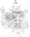
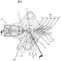
- 1 is an overall longitudinal sectional view of a high-pressure fuel supply pump according to a first embodiment in which the present invention is implemented. It is sectional drawing from another angle of the high-pressure fuel supply pump of a 1st Example. It is a cross-sectional view of the high pressure fuel supply pump of the first embodiment. 1 is an overall view of a system including a high-pressure fuel pump. It is sectional drawing of the discharge valve mechanism of 1st Example by which this invention was implemented. It is an exploded view of the discharge valve mechanism in which the present invention was implemented. It is a projection view of a discharge valve seat member. It is sectional drawing of a discharge valve member. It is sectional drawing of the discharge valve member of a 2nd Example. It is sectional drawing of the discharge valve member of a 3rd Example. Other embodiments
- the portion surrounded by a broken line indicates a main body of a high-pressure fuel supply pump (hereinafter referred to as a high-pressure pump), and the mechanisms and components shown in the broken line indicate that the high-pressure pump main body 1 is integrated.
- the fuel in the fuel tank 20 is pumped up by the feed pump 21 and sent to the suction joint 10 a of the pump body 1 through the suction pipe 28.
- the fuel that has passed through the suction joint 10a reaches the suction port 30a of the electromagnetic suction valve 30 constituting the variable capacity mechanism via the pressure pulsation reducing mechanism 9 and the suction passage 10b.
- the pulsation prevention mechanism 9 will be described later.
- the electromagnetic suction valve 30 includes an electromagnetic coil 308.
- the suction valve body 301 is biased in the valve opening direction due to the difference between the biasing force of the anchor spring 303 and the biasing force of the valve spring 304.
- the suction port 30d is open.
- the urging force of the anchor spring 303 and the urging force of the valve spring 304 are Energizing force of anchor spring 303> Energizing force of valve spring 304 It is set to become.
- the anchor spring 303 In a state in which the electromagnetic coil 308 is energized, the anchor spring 303 is maintained in a compressed state while the anchor 305 is moved leftward in FIG.
- the suction valve body 301 attached so that the tip of the electromagnetic plunger 305 contacts coaxially closes the suction port 30d connected to the pressurizing chamber 11 of the high-pressure pump by the biasing force of the valve spring 304.
- the electromagnetic coil 308 remains in a non-energized state and no magnetic biasing force acts. Therefore, the valve remains open by the biasing force of the intake valve body 301 anchor spring 303. Although the volume of the pressurizing chamber 11 decreases as the plunger 2 compresses, in this state, the fuel once sucked into the pressurizing chamber 11 passes through the suction valve body 301 in the valve-opened state once again to the suction passage 10b (suction). Since the pressure is returned to the port 30a), the pressure in the pressurizing chamber does not increase. This process is called a return process.
- the compression process of the plunger 2 includes a return process and a discharge process. Then, by controlling the energization timing of the electromagnetic coil 308 of the electromagnetic intake valve 30, the amount of high-pressure fuel that is discharged can be controlled. If the timing of energizing the electromagnetic coil 308 is advanced, the ratio of the return process in the compression process is small and the ratio of the discharge process is large. That is, the amount of fuel returned to the suction passage 10b (suction port 30a) is small, and the amount of fuel discharged at high pressure is large.
- the timing of energization is delayed, the ratio of the return process in the compression process is large and the ratio of the discharge process is small. That is, the amount of fuel returned to the suction passage 10b is large, and the amount of fuel discharged at high pressure is small.
- the timing of energizing the electromagnetic coil 308 is controlled by a command from the ECU.
- the amount of fuel discharged at a high pressure can be controlled to an amount required by the internal combustion engine by controlling the energization timing to the electromagnetic coil 308.
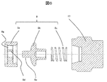
- a discharge valve mechanism 8 is provided at the outlet of the pressurizing chamber 11.
- the discharge valve mechanism 8 includes a discharge valve seat 8a, a discharge valve 8b, and a discharge valve spring 8c.
- the discharge valve 8b When there is no fuel differential pressure in the pressurizing chamber 11 and the fuel discharge port 12, the discharge valve 8b is biased by the discharge valve spring 8c. Is pressed against the discharge valve seat 8a and is in a closed state. Only when the fuel pressure in the pressurizing chamber 11 becomes higher than the fuel pressure in the fuel discharge port 12, the discharge valve 8 b opens against the discharge valve spring 8 c, and the fuel in the pressurization chamber 11 is discharged from the fuel discharge port. 12 is discharged to the common rail 23 through a high pressure.
- the fuel guided to the suction joint 10 a is pressurized to a high pressure by the reciprocating motion of the plunger 2 in the pressurizing chamber 11 of the pump body 1, and is pumped from the fuel discharge port 12 to the common rail 23.
- the common rail 23 is equipped with a direct injection injector 24 (so-called direct injection injector) and a pressure sensor 26.
- the direct injection injectors 24 are mounted according to the number of cylinders of the internal combustion engine, and are opened and closed according to a control signal from an engine control unit (ECU) 27 to inject fuel into the cylinders.
- ECU engine control unit
- the high pressure pump is fixed in close contact with the cylinder head 41 of the internal combustion engine.
- An O-ring 61 is fitted into the pump main body 1 to keep the cylinder head and the pump main body airtight.
- the pump body 1 is provided with a cylinder 6 that guides the forward and backward movement of the plunger 2 and has an end formed in a bottomed cylindrical shape so as to form a pressurizing chamber 11 therein. Further, the pressurizing chamber 11 is provided with a plurality of communication holes 11a so as to communicate with an electromagnetic suction valve 30 for supplying fuel and a discharge valve mechanism 8 for discharging fuel from the pressurizing chamber 11 to the discharge passage. .
- the cylinder 6 has a large-diameter portion and a small-diameter portion at the outer diameter, and the small-diameter portion is press-fitted into the pump body 1, and a step 6 a between the large-diameter portion and the small-diameter portion is pressure-bonded to the pump body 1 and added in the pressurizing chamber 11. Seals the pressurized fuel from leaking to the low pressure side.
- a tappet 3 that converts the rotational motion of the cam 5 attached to the camshaft of the internal combustion engine into a vertical motion and transmits it to the plunger 2.
- the plunger 2 is pressure-bonded to the tappet 3 by a spring 4 through a retainer 15. Thereby, the plunger 2 can be moved back and forth (reciprocated) up and down with the rotational movement of the cam 5.
- the plunger seal 13 held at the lower end of the inner periphery of the seal holder 7 is installed in a slidable contact with the outer periphery of the plunger 2 at the lower end of the cylinder 6 in the figure.
- the blow-by gap between 6 and 6 is sealed to prevent fuel from leaking outside the pump.
- lubricating oil including engine oil
- for lubricating the sliding portion in the internal combustion engine is prevented from flowing into the pump body 1 through the blow-by gap.
- the fuel pumped up by the feed pump 21 is sent to the pump body 1 through the suction joint 10a coupled to the suction pipe 28.
- the damper cover 14 is combined with the pump body 1 to form a low-pressure fuel chamber 10, and the fuel that has passed through the inlet joint 10a flows in.
- a fuel filter 102 is attached upstream of the low-pressure fuel chamber 10 by, for example, being press-fitted into the pump body 1 in order to remove foreign matters such as metal powder contained in the fuel.
- the low pressure fuel chamber 10 is provided with a pressure pulsation reducing mechanism 9 for reducing the pressure pulsation generated in the high pressure pump from spreading to the fuel pipe 28.
- a pressure pulsation reducing mechanism 9 for reducing the pressure pulsation generated in the high pressure pump from spreading to the fuel pipe 28.
- the pressure pulsation reducing mechanism 9 provided in the low-pressure fuel chamber 10 is formed by a metal damper 9a in which two corrugated disk-shaped metal plates are bonded together on the outer periphery and an inert gas such as argon is injected therein. The pressure pulsation is absorbed and reduced as the metal damper 9a expands and contracts.
- Reference numeral 9 b denotes a mounting bracket for fixing the metal damper 9 a to the inner peripheral portion of the pump body 1.
- the electromagnetic intake valve 30 includes an electromagnetic coil 308 and is a variable control mechanism that is connected to the ECU via a terminal 307 and controls the flow rate of the fuel by controlling the opening and closing of the intake valve by repeating energization and non-energization.
- the biasing force of the anchor spring 303 is transmitted to the suction valve body 301 via the anchor 305 and the anchor rod 302 formed integrally with the anchor 305.
- the biasing force of the valve spring 304 installed inside the suction valve body is Biasing Force of Anchor Spring 303>
- the biasing force of the valve spring 304 is set.
- the suction valve body 301 is biased in the valve opening direction and the suction port 30d is opened.
- the anchor rod 302 and the suction valve body 301 are in contact with each other at a portion indicated by 302b (state shown in FIG. 1).
- the magnetic urging force generated by energizing the coil 308 is set so that the anchor 305 has a force that can be attracted by overcoming the urging force of the anchor spring 303 on the stator 306 side.
- the anchor 303 moves to the stator 306 side (left side in the figure), and a stopper 302 a formed at the end of the anchor rod 302 abuts on and is locked to the anchor rod bearing 309.
- the movement amount of the anchor 301 and the movement amount of the suction valve body 301 are as follows: The clearance is set so that the amount of movement of the anchor 301> and the amount of movement of the suction valve body 301, and the contact portion 302b between the anchor rod 302 and the suction valve body 301 is opened. As a result, the suction valve body 301 has a valve spring 304. And the suction port 30d is closed.
- a suction valve seat 310 is inserted into the cylindrical boss 1b in a secret manner so that the suction valve body 301 can block the suction port 30d to the pressurizing chamber, and is fixed to the pump body 1.
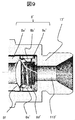
- the discharge valve mechanism 8 in the present embodiment will be described with reference to FIGS.
- the discharge valve mechanism 8 includes a discharge valve seat member 8a provided with a bearing 8d so as to hold reciprocating sliding at the center, and a discharge valve provided with a central shaft 8e slidable with respect to the bearing of the discharge valve sheet member 8a. It has member 8b.
- the discharge valve member 8b forms an annular contact surface 8f that can be kept oil-tight by contacting the discharge valve seat member 8a.
- the discharge valve spring 8c is provided to urge the discharge valve member 8b in the valve closing direction.
- a plurality of communication passages 8g are concentrically drilled around the bearing 8d in the discharge valve seat member 8a.
- the discharge valve seat member 8a is held in the pump body 1 by press-fitting, for example, and the discharge valve member 8b and the discharge valve spring 8c are inserted and sealed in the pump body 1 by the sealing plug 17 to constitute the discharge valve mechanism 8. is doing.
- the discharge valve mechanism 8 acts as a check valve that restricts the direction of fuel flow.
- the fuel that has passed through the discharge valve seat member 8a passes through the discharge passage 110, passes through the fuel discharge port 12, and flows downstream. Ensuring the discharge passage is at the design discretion. For example, even if the discharge passage is provided directly in the sealing plug 17, the discharge valve mechanism intended by the present invention can be configured.
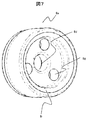
- the discharge valve seat member 8a will be described with reference to FIG.
- the above-described three communication paths 8g are concentrically arranged around the bearing 8d.
- three communication passages 8g are shown, but the number and size of holes are designed in consideration of necessary flow rate, pressure loss, balance and the like. That is, it can be said to be a design discretion for configuring the discharge valve intended by the present invention.
- the seat surface 8i that comes into contact with the discharge valve member 8b is formed in a conical shape. When viewed from the cross section, it is tapered.
- the discharge valve member 8b will be described with reference to FIG.
- the discharge valve member 8b is provided with a curved surface portion 8h, and this position is in contact with the discharge valve seat member 8a to form an annular contact surface 8f.
- the curved surface portion 8h in the present embodiment has a curvature radius R.
- the curved surface portion 8h of the discharge valve member 8b When the curved surface portion 8h of the discharge valve member 8b is pressed against the seat surface 8i of the discharge valve seat member 8a, the curved surface portion 8h is slightly deformed to form an annular contact surface 8f that can be kept oil tight. Since the contact portion of the curved surface portion 8h is formed with a uniform radius of curvature R on the entire circumference, the annular contact surface 8f can form a uniform sheet surface on the entire circumference. Further, since the seat surface is formed by the deformation caused by pressing of the curved surface portion 8h, the higher the pressure (back pressure) acting on the valve body, the wider the seat surface and the smaller the gap between the seat portions. The reason for the minute deformation of the curved surface portion and the sheet portion can be explained by generally known deformation accompanying Hertz contact.
- the curved surface portion 8h has not only the annular contact surface 8f portion but also the front and back (inner peripheral side and outer peripheral side) of the same radius of curvature R.
- the curved surface portion 8i pressed against the discharge valve seat member 8a has the same radius of curvature, and forms an annular contact surface 8f that can be kept oil tight.
- the portions having a constant radius of curvature are only the seat portion and its front and rear portions, the size and weight can be reduced as compared with a pure spherical valve body. Weight reduction is desirable to increase the responsiveness of the discharge valve.
- discharge valve spring 8c on the central axis side, it is possible to reduce the diameter of the entire discharge valve mechanism 8.
- the discharge valve spring 8c is provided on the inner side of the annular contact surface 8f, but the discharge valve mechanism according to claim 1 or 2 can be configured even if provided on the outer side of the annular contact surface 8f. It is.
- the discharge valve mechanism 8 ' includes a discharge valve seat member 8a', a discharge valve member 8b ', and a discharge valve spring 8c'. Downstream of this, there is a sealing plug 17 ′ for sealing the discharge valve mechanism 8 ′, and a discharge passage 110 ′ is provided in the sealing plug 17 ′.
- the discharge valve member 8b ' has a curved surface portion 8h', and the guide portion 8e 'is provided on the outer peripheral portion of the valve body.
- the outermost diameter of the discharge valve member is substantially the same as the outermost diameter of the curved surface portion 8h ', and the outermost diameter can be suppressed smaller than that of a pure spherical valve body.
- the spring 8c is housed on the inner peripheral wall surface of the guide portion 8e '. In this configuration, since the guide portion of the discharge valve member and the spring accommodating portion are configured in parallel, the overall length of the discharge valve member can be shortened. For the above reasons, a relatively small and light weight can be realized.
- FIG. 11 shows another embodiment.
- the discharge valve member has a tapered portion 8j, and a curved surface portion 8h '' having a minute length is provided at the end of the tapered portion 8j.
- the curved surface portion 8 ′′ is a portion that contacts the discharge valve seat member and forms an annular contact surface that can be kept oil tight.
- the discharge valve intended by the present invention can be configured basically by forming the annular contact surface by applying the curved surface portion to the sheet.
- the degree of freedom of the radius of curvature R is high, and a more appropriate radius of curvature can be selected according to the use environment. Further, as in the second embodiment, a reduction in size and weight can also be realized.
Abstract
Description
アンカーばね303の付勢力 > 弁ばね304の付勢力
となるよう設定されている。
後述するカムの回転により、プランジャ2が図4の下方に変位して吸入工程状態にある時は、加圧室11の容積は増加し加圧室11内の燃料圧力が低下する。この工程で加圧室11内の燃料圧力が吸入通路10b(吸入ポート30a)の圧力よりも低くなると、燃料は、開口状態にある吸入口30dを通り加圧室11に流入する。プランジャ2が吸入工程を終了し圧縮工程へと移行した場合、プランジャ2が圧縮工程(図1の上方へ移動する状態)に移る。ここで電磁コイル308は無通電状態を維持したままであり磁気付勢力は作用しない。よって、吸入弁体301アンカーばね303の付勢力により開弁したままである。加圧室11の容積は、プランジャ2の圧縮運動に伴い減少するが、この状態では、一度加圧室11に吸入された燃料が、再び開弁状態の吸入弁体301を通して吸入通路10b(吸入ポート30a)へと戻されるので、加圧室の圧力が上昇することは無い。この工程を戻し工程と称する。
アンカーばね303の付勢力 > 弁ばね304の付勢力
となるよう設定されており、結果、吸入弁体301は開弁方向に付勢され吸入口30dは開けられた状態となっている。この時アンカーロッド302と吸入弁体301は302bに示す部位で接触している(図1に示す状態)。
アンカー301の移動量>と吸入弁体301の移動量
となる様にクリアランスが設定されておりアンカーロッド302と吸入弁体301の接触部302bは開放され、結果吸入弁体301は、弁ばね304により付勢され吸入口30dは閉じられた状態となる。
2 プランジャ
6 シリンダ
8 吐出弁機構
9 圧力脈動低減機構
30 電磁吸入弁
100 リリーフ弁機構
Claims (6)
- ポンプに設けられたシリンダと、前記シリンダ内に摺動可能に設けられカムの回転に従って往復運動するプランジャと、前記プランジャ及び前記シリンダで形成される流体の加圧室と、前記加圧室と流体の吸入通路の間に形成される空間に設けられた電磁弁と、前記加圧室と流体の吐出通路の間に形成される空間に設けられた吐出弁と、を備えるプランジャ式高圧燃料ポンプであって、
前記吐出弁は前記加圧室に向かって径が小さくなる円錐状のシート面を有するシート部材と、前記シート部材に当接する弁部材と、前記弁部材を軸方向に摺動可能に拘束するガイド機構と、前記弁部材の前記シートとの当接面に形成されている曲面形状部と、前記弁部材を前記シートに向かって付勢するばねを備えていることを特徴とする高圧燃料ポンプ。 - 請求項1に記載の高圧燃料ポンプであって、前記ガイド機構は前記弁体と一体形勢されている支持部からなることを特徴とする高圧燃料ポンプ。
- 請求項1乃至2に記載の高圧燃料ポンプであって、前記ガイド機構は前記弁体よりも前記シート側に形成されることを特徴とする高圧燃料ポンプ。
- 請求項1乃至3に記載の高圧燃料ポンプであって、前記ばねの直径はシート径より小さいことを特徴とする高圧燃料ポンプ。
- 請求項2乃至4に記載の高圧燃料ポンプであって、前記シート部材には、前記支持部をガイドするガイド穴が設けられていることを特徴とする高圧燃料ポンプ。
- 請求項5に記載の高圧燃料ポンプであって、前記シート部材には、前記加圧室と前記吐出通路を連通する連通路が設けられており、前記連通路は前記ガイド穴の周りに複数個設けられていることを特徴とする高圧燃料ポンプ。
Priority Applications (3)
| Application Number | Priority Date | Filing Date | Title |
|---|---|---|---|
| CN201580022032.4A CN106255823B (zh) | 2014-04-25 | 2015-04-17 | 阀机构以及高压燃料泵 |
| JP2016514899A JP6370888B2 (ja) | 2014-04-25 | 2015-04-17 | 高圧燃料供給ポンプ |
| EP15782325.3A EP3135900B1 (en) | 2014-04-25 | 2015-04-17 | High-pressure fuel supply pump |
Applications Claiming Priority (2)
| Application Number | Priority Date | Filing Date | Title |
|---|---|---|---|
| JP2014-090817 | 2014-04-25 | ||
| JP2014090817 | 2014-04-25 |
Publications (1)
| Publication Number | Publication Date |
|---|---|
| WO2015163246A1 true WO2015163246A1 (ja) | 2015-10-29 |
Family
ID=54332412
Family Applications (1)
| Application Number | Title | Priority Date | Filing Date |
|---|---|---|---|
| PCT/JP2015/061777 WO2015163246A1 (ja) | 2014-04-25 | 2015-04-17 | 高圧燃料供給ポンプ |
Country Status (4)
| Country | Link |
|---|---|
| EP (1) | EP3135900B1 (ja) |
| JP (1) | JP6370888B2 (ja) |
| CN (1) | CN106255823B (ja) |
| WO (1) | WO2015163246A1 (ja) |
Cited By (4)
| Publication number | Priority date | Publication date | Assignee | Title |
|---|---|---|---|---|
| CN106150810A (zh) * | 2016-08-29 | 2016-11-23 | 温州巴腾电子科技有限公司 | 一种发动机喷油泵 |
| WO2019012970A1 (ja) | 2017-07-14 | 2019-01-17 | 日立オートモティブシステムズ株式会社 | 高圧燃料ポンプ |
| US10961816B1 (en) | 2020-01-20 | 2021-03-30 | Absolute Control, LLC | Oilwell choke |
| WO2021140829A1 (ja) * | 2020-01-07 | 2021-07-15 | 日立Astemo株式会社 | 吐出弁機構及びそれを備えた高圧燃料供給ポンプ |
Families Citing this family (3)
| Publication number | Priority date | Publication date | Assignee | Title |
|---|---|---|---|---|
| WO2018221077A1 (ja) * | 2017-05-31 | 2018-12-06 | 日立オートモティブシステムズ株式会社 | 電磁弁、電磁吸入弁機構、及び高圧燃料ポンプ |
| DE102019203967A1 (de) * | 2018-03-27 | 2019-10-02 | Keihin Corporation | Ventileinheit-befestigungsstruktur und fluidpumpe welche selbige verwendet |
| DE112020004456B4 (de) * | 2019-11-13 | 2024-03-14 | Hitachi Astemo, Ltd. | Kraftstoffzufuhrpumpe |
Citations (5)
| Publication number | Priority date | Publication date | Assignee | Title |
|---|---|---|---|---|
| JPS60159477A (ja) * | 1984-01-31 | 1985-08-20 | Atsugi Motor Parts Co Ltd | 弁装置 |
| JPH0744361U (ja) * | 1993-10-21 | 1995-11-14 | サイエンス株式会社 | 逆止弁 |
| JPH11100750A (ja) * | 1997-07-25 | 1999-04-13 | Kyotai Haku | ウォータージェット織機用チェックバルブ |
| JP2002266726A (ja) * | 2001-03-08 | 2002-09-18 | Hitachi Ltd | 燃料供給ポンプ |
| JP2014001738A (ja) * | 2013-09-02 | 2014-01-09 | Hitachi Automotive Systems Ltd | 内燃機関の高圧燃料ポンプ制御装置 |
Family Cites Families (8)
| Publication number | Priority date | Publication date | Assignee | Title |
|---|---|---|---|---|
| GB521060A (en) * | 1937-11-13 | 1940-05-10 | Rudolf L Orange | Improvements in or relating to pressure control systems for fuel injection pumps |
| US6238190B1 (en) * | 1999-03-18 | 2001-05-29 | Diesel Technology Company | Fuel injection pump and snubber valve assembly |
| DE60224106T2 (de) * | 2002-06-20 | 2008-11-27 | Hitachi, Ltd. | Steuervorrichtung für hochdruckkraftstoffpumpe von verbrennungsmotor |
| DE102004037419B3 (de) * | 2004-07-30 | 2006-02-16 | Siemens Ag | Ventil für den Einsatz in einer kraftstoffführenden Leitung eines Kraftfahrzeuges |
| DE102005024042A1 (de) * | 2005-05-25 | 2006-11-30 | Robert Bosch Gmbh | Auslassstutzen für eine Hochdruckpumpe |
| DE602006010981D1 (de) * | 2006-05-19 | 2010-01-21 | Kraftstoffhochdruckpumpe | |
| BR112013029205A2 (pt) * | 2011-05-13 | 2017-02-14 | Mikuni Kogyo Kk | dispositivo de bomba de combustível de alta pressão |
| CN202182020U (zh) * | 2011-08-25 | 2012-04-04 | 博世汽车柴油系统股份有限公司 | 用于高压流体泵中的流体进出阀 |
-
2015
- 2015-04-17 EP EP15782325.3A patent/EP3135900B1/en active Active
- 2015-04-17 WO PCT/JP2015/061777 patent/WO2015163246A1/ja active Application Filing
- 2015-04-17 JP JP2016514899A patent/JP6370888B2/ja active Active
- 2015-04-17 CN CN201580022032.4A patent/CN106255823B/zh active Active
Patent Citations (5)
| Publication number | Priority date | Publication date | Assignee | Title |
|---|---|---|---|---|
| JPS60159477A (ja) * | 1984-01-31 | 1985-08-20 | Atsugi Motor Parts Co Ltd | 弁装置 |
| JPH0744361U (ja) * | 1993-10-21 | 1995-11-14 | サイエンス株式会社 | 逆止弁 |
| JPH11100750A (ja) * | 1997-07-25 | 1999-04-13 | Kyotai Haku | ウォータージェット織機用チェックバルブ |
| JP2002266726A (ja) * | 2001-03-08 | 2002-09-18 | Hitachi Ltd | 燃料供給ポンプ |
| JP2014001738A (ja) * | 2013-09-02 | 2014-01-09 | Hitachi Automotive Systems Ltd | 内燃機関の高圧燃料ポンプ制御装置 |
Cited By (12)
| Publication number | Priority date | Publication date | Assignee | Title |
|---|---|---|---|---|
| CN106150810A (zh) * | 2016-08-29 | 2016-11-23 | 温州巴腾电子科技有限公司 | 一种发动机喷油泵 |
| WO2019012970A1 (ja) | 2017-07-14 | 2019-01-17 | 日立オートモティブシステムズ株式会社 | 高圧燃料ポンプ |
| CN110832188A (zh) * | 2017-07-14 | 2020-02-21 | 日立汽车系统株式会社 | 高压燃料泵 |
| JPWO2019012970A1 (ja) * | 2017-07-14 | 2020-03-19 | 日立オートモティブシステムズ株式会社 | 高圧燃料ポンプ |
| US11248573B2 (en) | 2017-07-14 | 2022-02-15 | Hitachi Astemo, Ltd. | High-pressure fuel pump |
| WO2021140829A1 (ja) * | 2020-01-07 | 2021-07-15 | 日立Astemo株式会社 | 吐出弁機構及びそれを備えた高圧燃料供給ポンプ |
| JPWO2021140829A1 (ja) * | 2020-01-07 | 2021-07-15 | ||
| CN114787497A (zh) * | 2020-01-07 | 2022-07-22 | 日立安斯泰莫株式会社 | 排出阀机构及具备该排出阀机构的高压燃料供给泵 |
| JP7273196B2 (ja) | 2020-01-07 | 2023-05-12 | 日立Astemo株式会社 | 吐出弁機構及びそれを備えた高圧燃料供給ポンプ |
| US11781513B2 (en) | 2020-01-07 | 2023-10-10 | Hitachi Astemo, Ltd. | Discharge valve mechanism and high-pressure fuel supply pump including the same |
| CN114787497B (zh) * | 2020-01-07 | 2023-11-24 | 日立安斯泰莫株式会社 | 排出阀机构及具备该排出阀机构的高压燃料供给泵 |
| US10961816B1 (en) | 2020-01-20 | 2021-03-30 | Absolute Control, LLC | Oilwell choke |
Also Published As
| Publication number | Publication date |
|---|---|
| CN106255823A (zh) | 2016-12-21 |
| CN106255823B (zh) | 2020-09-29 |
| EP3135900B1 (en) | 2019-01-30 |
| EP3135900A1 (en) | 2017-03-01 |
| EP3135900A4 (en) | 2017-12-13 |
| JP6370888B2 (ja) | 2018-08-08 |
| JPWO2015163246A1 (ja) | 2017-04-13 |
Similar Documents
| Publication | Publication Date | Title |
|---|---|---|
| JP6370888B2 (ja) | 高圧燃料供給ポンプ | |
| JP4945504B2 (ja) | 高圧燃料供給ポンプ | |
| JP6470267B2 (ja) | 高圧燃料供給ポンプ | |
| JP2007138762A (ja) | 高圧燃料供給ポンプ | |
| JP6561158B2 (ja) | 電磁弁、この電磁弁を吸入弁機構として備えた高圧燃料供給ポンプ | |
| JP6527066B2 (ja) | 高圧燃料供給ポンプ | |
| JP6934519B2 (ja) | 高圧燃料ポンプ | |
| JP6649483B2 (ja) | 高圧燃料供給ポンプ | |
| JP6697552B2 (ja) | 高圧燃料供給ポンプ | |
| JP6268279B2 (ja) | 高圧燃料供給ポンプ | |
| JP6572241B2 (ja) | バルブ機構、及びこれを備えた高圧燃料供給ポンプ | |
| JP2018105274A (ja) | 高圧燃料供給ポンプ | |
| JP6373785B2 (ja) | 高圧燃料供給ポンプ | |
| WO2018225479A1 (ja) | 高圧燃料ポンプ | |
| EP4286680A1 (en) | Electromagnetic valve mechanism and fuel pump | |
| JP2020133490A (ja) | 高圧燃料供給ポンプ及びリリーフ弁機構 | |
| JP2019203437A (ja) | 高圧燃料供給ポンプ | |
| JP7248783B2 (ja) | 電磁弁機構及びそれを備えた高圧燃料供給ポンプ | |
| JP6596542B2 (ja) | バルブ機構及びこれを備えた高圧燃料供給ポンプ | |
| JP2019027334A (ja) | 高圧燃料供給ポンプ | |
| JP6385840B2 (ja) | バルブ機構及びこれを備えた高圧燃料供給ポンプ | |
| JP2017072027A (ja) | 高圧燃料供給ポンプ | |
| JP2018009495A (ja) | 高圧燃料供給ポンプ |
Legal Events
| Date | Code | Title | Description |
|---|---|---|---|
| 121 | Ep: the epo has been informed by wipo that ep was designated in this application |
Ref document number: 15782325 Country of ref document: EP Kind code of ref document: A1 |
|
| ENP | Entry into the national phase |
Ref document number: 2016514899 Country of ref document: JP Kind code of ref document: A |
|
| REEP | Request for entry into the european phase |
Ref document number: 2015782325 Country of ref document: EP |
|
| WWE | Wipo information: entry into national phase |
Ref document number: 2015782325 Country of ref document: EP |
|
| NENP | Non-entry into the national phase |
Ref country code: DE |