WO2015159595A1 - 電池パック - Google Patents
電池パック Download PDFInfo
- Publication number
- WO2015159595A1 WO2015159595A1 PCT/JP2015/055753 JP2015055753W WO2015159595A1 WO 2015159595 A1 WO2015159595 A1 WO 2015159595A1 JP 2015055753 W JP2015055753 W JP 2015055753W WO 2015159595 A1 WO2015159595 A1 WO 2015159595A1
- Authority
- WO
- WIPO (PCT)
- Prior art keywords
- overlapping portion
- case
- battery pack
- bent
- outer overlapping
- Prior art date
Links
Images

Classifications
-
- H—ELECTRICITY
- H01—ELECTRIC ELEMENTS
- H01M—PROCESSES OR MEANS, e.g. BATTERIES, FOR THE DIRECT CONVERSION OF CHEMICAL ENERGY INTO ELECTRICAL ENERGY
- H01M50/00—Constructional details or processes of manufacture of the non-active parts of electrochemical cells other than fuel cells, e.g. hybrid cells
- H01M50/20—Mountings; Secondary casings or frames; Racks, modules or packs; Suspension devices; Shock absorbers; Transport or carrying devices; Holders
- H01M50/233—Mountings; Secondary casings or frames; Racks, modules or packs; Suspension devices; Shock absorbers; Transport or carrying devices; Holders characterised by physical properties of casings or racks, e.g. dimensions
- H01M50/24—Mountings; Secondary casings or frames; Racks, modules or packs; Suspension devices; Shock absorbers; Transport or carrying devices; Holders characterised by physical properties of casings or racks, e.g. dimensions adapted for protecting batteries from their environment, e.g. from corrosion
-
- H—ELECTRICITY
- H01—ELECTRIC ELEMENTS
- H01M—PROCESSES OR MEANS, e.g. BATTERIES, FOR THE DIRECT CONVERSION OF CHEMICAL ENERGY INTO ELECTRICAL ENERGY
- H01M50/00—Constructional details or processes of manufacture of the non-active parts of electrochemical cells other than fuel cells, e.g. hybrid cells
- H01M50/20—Mountings; Secondary casings or frames; Racks, modules or packs; Suspension devices; Shock absorbers; Transport or carrying devices; Holders
- H01M50/204—Racks, modules or packs for multiple batteries or multiple cells
- H01M50/207—Racks, modules or packs for multiple batteries or multiple cells characterised by their shape
- H01M50/209—Racks, modules or packs for multiple batteries or multiple cells characterised by their shape adapted for prismatic or rectangular cells
-
- H—ELECTRICITY
- H01—ELECTRIC ELEMENTS
- H01M—PROCESSES OR MEANS, e.g. BATTERIES, FOR THE DIRECT CONVERSION OF CHEMICAL ENERGY INTO ELECTRICAL ENERGY
- H01M50/00—Constructional details or processes of manufacture of the non-active parts of electrochemical cells other than fuel cells, e.g. hybrid cells
- H01M50/20—Mountings; Secondary casings or frames; Racks, modules or packs; Suspension devices; Shock absorbers; Transport or carrying devices; Holders
- H01M50/271—Lids or covers for the racks or secondary casings
-
- B—PERFORMING OPERATIONS; TRANSPORTING
- B60—VEHICLES IN GENERAL
- B60J—WINDOWS, WINDSCREENS, NON-FIXED ROOFS, DOORS, OR SIMILAR DEVICES FOR VEHICLES; REMOVABLE EXTERNAL PROTECTIVE COVERINGS SPECIALLY ADAPTED FOR VEHICLES
- B60J10/00—Sealing arrangements
- B60J10/20—Sealing arrangements characterised by the shape
- B60J10/23—Sealing arrangements characterised by the shape assembled from two or more parts
- B60J10/235—Sealing arrangements characterised by the shape assembled from two or more parts the parts being joined along their longitudinal direction
-
- B—PERFORMING OPERATIONS; TRANSPORTING
- B60—VEHICLES IN GENERAL
- B60R—VEHICLES, VEHICLE FITTINGS, OR VEHICLE PARTS, NOT OTHERWISE PROVIDED FOR
- B60R13/00—Elements for body-finishing, identifying, or decorating; Arrangements or adaptations for advertising purposes
- B60R13/06—Sealing strips
-
- H—ELECTRICITY
- H01—ELECTRIC ELEMENTS
- H01M—PROCESSES OR MEANS, e.g. BATTERIES, FOR THE DIRECT CONVERSION OF CHEMICAL ENERGY INTO ELECTRICAL ENERGY
- H01M2220/00—Batteries for particular applications
- H01M2220/20—Batteries in motive systems, e.g. vehicle, ship, plane
-
- Y—GENERAL TAGGING OF NEW TECHNOLOGICAL DEVELOPMENTS; GENERAL TAGGING OF CROSS-SECTIONAL TECHNOLOGIES SPANNING OVER SEVERAL SECTIONS OF THE IPC; TECHNICAL SUBJECTS COVERED BY FORMER USPC CROSS-REFERENCE ART COLLECTIONS [XRACs] AND DIGESTS
- Y02—TECHNOLOGIES OR APPLICATIONS FOR MITIGATION OR ADAPTATION AGAINST CLIMATE CHANGE
- Y02E—REDUCTION OF GREENHOUSE GAS [GHG] EMISSIONS, RELATED TO ENERGY GENERATION, TRANSMISSION OR DISTRIBUTION
- Y02E60/00—Enabling technologies; Technologies with a potential or indirect contribution to GHG emissions mitigation
- Y02E60/10—Energy storage using batteries
Definitions
- the present invention relates to a battery pack.
- the battery module described in Patent Literature 1 includes a plurality of unit cells (battery cells) and a module case that houses the unit cells.
- liquid such as water or dust that has entered the case may cause a short circuit of the battery cell, which may cause the battery cell to fail. For this reason, improvement of the sealing performance of a case is desired.
- An object of the present invention is to provide a battery pack with improved sealing performance of a case.
- a battery pack including a battery cell and a case for accommodating the battery cell.
- the case is sandwiched between a case body having an opening, a lid that is fixed to the case body and closes the opening, and an end surface surrounding the opening of the case body and the lid, and follows the shape of the opening.
- a long and bent sealing material having elastic force.
- the sealing material applies a restoring force to the inner overlapping portion, the outer overlapping portion that overlaps with the inner overlapping portion and disposed outside the inner overlapping portion, and the inner overlapping portion is pressed against the outer overlapping portion.
- an inner bent portion is provided.
- a long sealing material may be bent and placed between the case body and the lid to ensure the case's sealing performance.
- the sealing performance of the case cannot be ensured.
- the inner overlapping portion is pressed against the outer overlapping portion by the restoring force acting on the inner overlapping portion.
- the adhesiveness of an inner side overlap part and an outer side overlap part improves. Therefore, it becomes difficult to produce the clearance gap between an inner side overlap part and an outer side overlap part, and the sealing performance between a case main body and a cover body, ie, the sealing performance of a case, improves.
- the disassembled perspective view which shows the battery pack which concerns on one Embodiment of this invention.
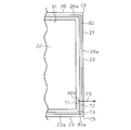
- the front view which shows the case main body of a battery pack.
- the partial top view which expands and shows the inner side overlapping part and outer side overlapping part of a sealing material.
- the partial top view which expands and shows the inner side overlapping part and outer side overlapping part of the sealing material which concern on a modification.
- the partial top view which expands and shows the inner side overlap part and outer side overlap part which concern on a modification.
- the partial top view which expands and shows the inner side overlap part and outer side overlap part which concern on a modification.
- the vertical direction is the vertical direction.
- the battery pack 10 has a case 11.
- a plurality of battery cells 12 are accommodated in the case 11.
- the case 11 has a bottomed cylindrical case body 21, a flat lid 13, and a sealing material 40.
- the sealing material 40 is disposed between the case main body 21 and the lid body 13.
- the case body 21 has a flat base 22 and six rectangular flat walls 23 to 28. Each of the wall portions 23 to 28 extends from the periphery of the base portion 22 in the thickness direction of the base portion 22.
- a first side wall portion 24 and a second side wall portion 25 are provided at both ends of the lower wall portion 23 in the longitudinal direction.
- the first and second side wall portions 24 and 25 extend in the thickness direction of the lower wall portion 23.
- the length of the first side wall portion 24 is larger than that of the second side wall portion 25.
- An upper wall portion 26 is provided at an end of the first side wall portion 24 opposite to the lower wall portion 23.
- the upper wall portion 26 extends in the thickness direction of the first side wall portion 24.
- the lower wall portion 23 faces the upper wall portion 26.
- the length of the upper wall portion 26 is smaller than that of the lower wall portion 23.
- An inclined wall portion 27 is provided at an end of the second side wall portion 25 opposite to the lower wall portion 23.
- the inclined wall portion 27 extends obliquely so as to approach both the first side wall portion 24 and the upper wall portion 26.
- the inclined wall portion 27 is connected to the upper wall portion 26 via the third side wall portion 28.
- the wall portions 23 to 28 are connected in a frame shape.
- the second side wall part 25 and the third side wall part 28 are opposed to the first side wall part 24.
- the case 11 is disposed with the lower wall portion 23 facing downward and the upper wall portion 26 facing upward.
- a connector 29 is provided on the third side wall 28.
- the connector 29 protrudes from the third side wall portion 28 to the outside of the case 11.
- the connector 29 is electrically connected to the battery cell 12 by a harness (not shown).
- the third side wall portion 28 is disposed between the second side wall portion 25 and the first side wall portion 24.
- the third side wall portion 28 and the inclined wall portion 27 form a recess 30 that is recessed inside the case 11.
- a region surrounded by the inclined wall portion 27 and the third side wall portion 28 is partitioned by the recess 30 as a region where the connector 29 is disposed.
- the case body 21 has an opening 31 surrounded by the wall portions 23 to 28.
- Each of the walls 23 to 28 has end faces 23 a to 28 a surrounding the opening 31.
- a sealing material 40 is attached to the end surfaces 23a to 28a of the wall portions 23 to 28.
- the sealing material 40 is manufactured using a material having elasticity such as rubber or a resin sponge.
- the sealing material 40 is made of a single long bar and is bent along the shape of the opening 31.
- the sealing material 40 is disposed so as to surround the opening 31.
- a lid 13 that closes the opening 31 of the case body 21 is fixed to each of the walls 23 to 28.
- the sealing material 40 is crushed by being sandwiched between the end faces 23a to 28a of the wall portions 23 to 28 and the lid body 13. In this way, the sealing performance between the case main body 21 and the lid body 13, that is, the sealing performance of the case 11 is ensured.
- the sealing material 40 has six bent portions 41 to 46.
- the first bent portion 41 is bent at an angle C1 where the upper wall portion 26 and the third side wall portion 28 intersect.
- the second bent portion 42 is bent at an angle C ⁇ b> 2 where the third side wall portion 28 and the inclined wall portion 27 intersect.
- the third bent portion 43 is bent at an angle C3 where the inclined wall portion 27 and the second side wall portion 25 intersect.
- the fourth bent portion 44 is bent at an angle C4 where the second side wall portion 25 and the lower wall portion 23 intersect.
- the fifth bent portion 45 is bent at an angle C5 where the lower wall portion 23 and the first side wall portion 24 intersect.
- the sixth bent part 46 is bent at an angle C6 where the first side wall part 24 and the upper wall part 26 intersect.
- the sealing material 40 has a first end 40a at one end in the longitudinal direction and a second end 40b at the other end.
- the sealing material 40 has an upper portion 51 between the first end portion 40 a and the first bent portion 41.
- the upper portion 51 is disposed along the end surface 26 a of the upper wall portion 26.
- the sealing material 40 has a side portion 52 between the first bent portion 41 and the second bent portion 42.
- the side portion 52 is disposed along the end surface 28 a of the third side wall portion 28.
- the sealing material 40 has an inclined portion 53 between the second bent portion 42 and the third bent portion 43.
- the inclined portion 53 is disposed along the end surface 27 a of the inclined wall portion 27.
- the sealing material 40 has a side portion 54 between the third bent portion 43 and the fourth bent portion 44.
- the side portion 54 is disposed along the end surface 25 a of the second side wall portion 25.
- the sealing material 40 has a lower portion 55 between the fourth bent portion 44 and the fifth bent portion 45.
- the lower portion 55 is disposed along the end surface 23 a of the lower wall portion 23.
- the sealing material 40 has a side portion 56 between the fifth bent portion 45 and the sixth bent portion 46.
- the side portion 56 is disposed along the end surface 24 a of the first side wall portion 24.
- the sealing material 40 has an inner overlapping portion 57 between the sixth bent portion 46 and the second end portion 40 b.
- the inner overlapping portion 57 is disposed along the end surface 26 a of the upper wall portion 26.
- the inner overlapping portion 57 is disposed inside the upper portion 51.
- the length of the inner overlapping portion 57 is smaller than that of the upper portion 51.
- the inner overlapping portion 57 is in close contact with a part of the upper portion 51.
- the upper portion 51 has an outer overlapping portion 58 at a portion overlapping the inner overlapping portion 57.
- the outer overlapping portion 58 is disposed along the end surface 26 a of the upper wall portion 26.
- the outer overlapping portion 58 is disposed outside the inner overlapping portion 57.
- the outer overlapping portion 58 covers the sixth bent portion 46 from above.
- the inner overlapping portion 57 and the outer overlapping portion 58 are disposed on the uppermost end surface 26a among the end surfaces 23a to 28a of the wall portions 23 to 28.
- the sealing material 40 has an elastic force. For this reason, when the sealing material 40 is bent, a restoring force for restoring the original shape acts on the sealing material 40.
- the restoring force F ⁇ b> 1 acting on the inner overlapping portion 57 depends on the sixth bent portion 46 closest to the inner overlapping portion 57.
- the sixth bent portion 46 is bent from the end surface 24 a of the first side wall portion 24 toward the end surface 26 a of the upper wall portion 26.
- a restoring force F ⁇ b> 1 acts on the inner overlapping portion 57 on the outer side so that the inner overlapping portion 57 is aligned with the side portion 56.
- the restoring force F ⁇ b> 1 of the inner overlapping portion 57 acts on the outer overlapping portion 58.
- the sixth bent portion 46 is an inner bent portion that applies a restoring force F1 to the inner overlapping portion 57 so that the inner overlapping portion 57 is pressed against the outer overlapping portion 58.
- a restoring force F2 acts on the outer overlapping portion 58.
- the restoring force F ⁇ b> 2 depends on the first bent portion 41 that is the bent portion closest to the upper portion 51 including the outer overlapping portion 58.
- a restoring force F2 acts on the outer overlapping portion 58 to make the outer overlapping portion 58 in a straight line with the side portion 52. That is, the restoring force acts on the inner overlapping portion 57 and the outer overlapping portion 58 in the same direction.
- the restoring force F ⁇ b> 2 acts on the outer overlapping portion 58 in a direction away from the inner overlapping portion 57.
- the restoring force acting on the sealing material 40 depends on the distance from each bent portion 41 to 46. That is, the closer the distance from each of the bent portions 41 to 46, the greater the restoring force that acts on the sealing material 40.
- the magnitude of the restoring force F ⁇ b> 1 acting on the inner overlapping portion 57 depends on the distance from the sixth bent portion 46.
- the magnitude of the restoring force F ⁇ b> 2 acting on the outer overlapping portion 58 depends on the distance from the first bent portion 41. The distance from the first bent portion 41 to the outer overlapping portion 58 is larger than the distance from the sixth bent portion 46 to the inner overlapping portion 57.
- the restoring force F2 acting on the outer overlapping portion 58 is smaller than the restoring force F1 acting on the inner overlapping portion 57. Therefore, even if the direction of the restoring force acting on the inner overlapping portion 57 and the outer overlapping portion 58 is the same, the inner overlapping portion 57 is pressed against the outer overlapping portion 58.
- the long sealing material 40 is disposed between the case main body 21 and the lid body 13 in a bent state.
- the sealing material 40 is disposed between the case main body 21 and the lid body 13 so as to surround the opening 31 without a gap.
- the sealing material 40 is disposed so as to have an inner overlapping portion 57 and an outer overlapping portion 58 that overlap each other. At this time, if a gap is generated between the inner overlapping portion 57 and the outer overlapping portion 58, the sealing performance may not be ensured.
- the restoring force F ⁇ b> 1 acts on the inner overlapping portion 57 toward the outer overlapping portion 58.
- the restoring force F ⁇ b> 1 acts on the inner overlapping portion 57 toward the outer overlapping portion 58. For this reason, the adhesiveness of the inner side overlap part 57 and the outer side overlap part 58 improves, and the sealing performance of the case 11 improves. For this reason, it becomes difficult for liquid, dust, or the like to enter the case 11 from the outside. Therefore, the short circuit of the battery cell 12 is suppressed.
- the inner overlapping portion 57 and the outer overlapping portion 58 overlap each other at the uppermost portion of the case 11.
- the battery pack 10 may be housed in a housing portion such as a vehicle.
- the inner overlapping portion 57 and the outer overlapping portion 58 are provided in the lower portion of the case 11, the liquid staying in the storage portion easily enters the case 11.
- the inner overlapping portion 57 and the outer overlapping portion 58 at the uppermost portion of the case 11, it is difficult for the liquid staying in the storage portion to enter the case 11.
- the outer overlapping portion 58 covers the sixth bent portion 46 from above.
- the outer overlapping portion 58 does not cover the sixth bent portion 46, liquid stays between the sixth bent portion 46 and the inner overlapping portion 57, or the joint between the inner overlapping portion 57 and the outer overlapping portion 58.
- by extending the outer overlapping portion 58 to a position that covers the sixth bent portion 46 it is possible to prevent liquid from staying near the joint between the inner overlapping portion 57 and the outer overlapping portion 58. Therefore, it is possible to prevent liquid from entering the case 11.
- an inner overlapping portion 61 and an outer overlapping portion 62 may be disposed on the end surface 27 a of the inclined wall portion 27.
- a restoring force F3 acts on the inner overlapping portion 61 by an inner bent portion 63 bent at a corner C3.
- a restoring force F4 acts on the outer overlapping portion 62 inward due to the outer bent portion 64 bent at the corner C2. That is, the restoring force acts on the inner overlapping portion 61 and the outer overlapping portion 62 in a direction approaching each other. For this reason, the adhesiveness of the inner side overlapping part 61 and the outer side overlapping part 62 improves, and the sealing performance of the case 11 further improves.
- the inclined wall portion 27 is one of the wall portions that define the recess 30. Further, the inclined portion 27 is not provided with the connector 29. Double sealing materials 40 are provided at the portions where the inner overlapping portion 61 and the outer overlapping portion 62 are arranged. For this reason, the end surface of the wall portion of the case 11 where the inner overlapping portion 61 and the outer overlapping portion 62 are arranged needs to have a large area. In this case, it is conceivable to increase the end surface area by thickening the wall. However, this method is not preferable because it may obstruct the arrangement of other members other than the battery pack 10. In this respect, the wall section that defines the recess 30 in which the connector 29 is disposed has the following advantages.
- the inner overlapping portion 71 and the outer overlapping portion 72 may be disposed on the first side wall portion 24.
- a restoring force F5 acts on the inner overlapping portion 71 on the outer side by an inner bent portion 73 bent at a corner C5.
- the adhesiveness of the inner side overlapping part 71 and the outer side overlapping part 72 improves, and the sealing performance of the case 11 further improves.
- the inner overlapping portion 71 extends upward and the outer overlapping portion 72 extends downward.
- the joint between the inner overlapping portion 71 and the outer overlapping portion 72 is exposed upward.
- the liquid moves from the top to the bottom, the liquid easily enters from the seam exposed upward.
- the inner overlapping portion 71 extends upward and the outer overlapping portion 72 extends downward, the seam is not exposed facing upward, and the liquid can be prevented from entering the case 11.
- an inner overlapping portion 81 and an outer overlapping portion 82 may be arranged on the third side wall portion 28. Also in this case, the restoring forces F6 and F7 act on the inner overlapping portion 81 and the outer overlapping portion 82 in the direction of approaching each other. For this reason, the adhesiveness of the inner side overlapping part 81 and the outer side overlapping part 82 improves.
- the inner overlapping portion 57 and the outer overlapping portion 58 may be disposed on the second side wall portion 25 and the lower wall portion 23. In other words, the inner overlapping portion 57 and the outer overlapping portion 58 may be arranged at arbitrary positions on the end faces 23 a to 28 a surrounding the opening 31.
- the shape of the opening 31 may be any shape such as a quadrangle or a pentagon.
- a plurality of sealing materials 40 may be used.
- the overlapping portions of the sealing materials 40 are the inner overlapping portion 57 and the outer overlapping portion 58. Further, as the number of sealing materials 40 increases, the number of inner overlapping portions 57 and outer overlapping portions 58 also increases.
Landscapes
- Chemical & Material Sciences (AREA)
- Chemical Kinetics & Catalysis (AREA)
- Electrochemistry (AREA)
- General Chemical & Material Sciences (AREA)
- Battery Mounting, Suspending (AREA)
- Sealing Battery Cases Or Jackets (AREA)
Abstract
電池パックは、ケースを有している。ケースには、複数の電池セルが収容されている。ケースは、有底筒状のケース本体と、平板状の蓋体とを有している。ケース本体の各壁部は、開口部を囲む端面を有している。各壁部の端面には、シール材が設けられている。シール材は、互いに重なり合う内側重なり部と外側重なり部とを有している。内側重なり部には、第6の屈曲部によって、外側重なり部に向けて復元力が作用している。
Description
本発明は、電池パックに関する。
電池パックの一例が、特許文献1に記載されている。特許文献1に記載の電池モジュールは、複数の単電池(電池セル)と、単電池を収容するモジュールケースとを備えている。
ところで、ケース内に浸入した水などの液体やほこりは、電池セルの短絡の原因となり、電池セルを故障させるおそれがある。このため、ケースのシール性の向上が望まれている。
本発明の目的は、ケースのシール性が向上する電池パックを提供することにある。
上記課題を解決するため、本願発明の第一の態様によれば、電池セルと、電池セルを収容するケースとを備えた電池パックが提供される。ケースは、開口部を有するケース本体と、ケース本体に固定されて開口部を閉塞する蓋体と、ケース本体の開口部を囲む端面と蓋体との間に挟持され、開口部の形状に沿って屈曲された長尺状の弾性力を有するシール材とを備えている。シール材は、内側重なり部と、内側重なり部と重なり合うとともに内側重なり部よりも外側に配置される外側重なり部と、内側重なり部が外側重なり部に押しつけられるよう内側重なり部に復元力を作用させる内側屈曲部とを有する。
長尺状のシール材を屈曲させてケース本体と蓋体との間に配置し、ケースのシール性を確保することがある。この場合、ケース本体と蓋体との間に隙間が生じないように、シール材の一部を重ね合わせる必要がある。このとき、内側重なり部と外側重なり部との間に隙間が生じていると、ケースのシール性が確保できない。この点、上記構成によれば、内側重なり部に作用する復元力によって、内側重なり部が外側重なり部に押しつけられる。これにより、内側重なり部と外側重なり部との密着性が向上する。よって、内側重なり部と外側重なり部との隙間が生じにくくなり、ケース本体と蓋体との間のシール性、すなわち、ケースのシール性が向上する。
以下、本発明の電池パックを具体化した一実施形態について図1~図3を参照して説明する。以下の説明に際し、上下方向を、鉛直方向の上下方向とする。
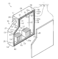
図1に示すように、電池パック10は、ケース11を有している。ケース11には、複数の電池セル12が収容されている。ケース11は、有底筒状のケース本体21と、平板状の蓋体13と、シール材40とを有している。シール材40は、ケース本体21と蓋体13との間に配置されている。ケース本体21は、平板状の基部22と、矩形平板状の6つの壁部23~28とを有している。各壁部23~28は、基部22の周縁から基部22の厚み方向に延びている。
図1に示すように、電池パック10は、ケース11を有している。ケース11には、複数の電池セル12が収容されている。ケース11は、有底筒状のケース本体21と、平板状の蓋体13と、シール材40とを有している。シール材40は、ケース本体21と蓋体13との間に配置されている。ケース本体21は、平板状の基部22と、矩形平板状の6つの壁部23~28とを有している。各壁部23~28は、基部22の周縁から基部22の厚み方向に延びている。
図2に示すように、下壁部23の長手方向の両端には、第1の側壁部24と第2の側壁部25とがそれぞれ設けられている。第1及び第2の側壁部24,25は、下壁部23の厚み方向に延びている。第1の側壁部24の長さは、第2の側壁部25よりも大きい。第1の側壁部24において下壁部23と反対側の端部には、上壁部26が設けられている。上壁部26は、第1の側壁部24の厚み方向に延びている。下壁部23は、上壁部26と対向している。上壁部26の長さは、下壁部23よりも小さい。第2の側壁部25において下壁部23と反対側の端部には、傾斜壁部27が設けられている。傾斜壁部27は、第1の側壁部24及び上壁部26の両方に近付くよう斜めに延びている。傾斜壁部27は、第3の側壁部28を介して上壁部26と繋っている。こうして、各壁部23~28は、枠状に繋がれている。第2の側壁部25及び第3の側壁部28は、第1の側壁部24と対向している。ケース11は、下壁部23を下方に向け上壁部26を上方に向けて配置される。
第3の側壁部28には、コネクタ29が設けられている。コネクタ29は、第3の側壁部28からケース11の外側に突出している。コネクタ29は、図示しないハーネスなどによって電池セル12と電気的に接続されている。第3の側壁部28は、第2の側壁部25と第1の側壁部24との間に配置されている。第3の側壁部28は、傾斜壁部27と共に、ケース11の内側に凹む凹部30を形成している。凹部30により、傾斜壁部27と第3の側壁部28とによって囲まれた領域が、コネクタ29が配置される領域として、区画されている。
ケース本体21は、各壁部23~28によって囲まれた開口部31を有している。各壁部23~28は、開口部31を囲む端面23a~28aを有している。各壁部23~28の端面23a~28aには、シール材40が貼り付けられている。シール材40は、ゴムや樹脂系のスポンジなどの弾性力を有する材料を用いて製造される。シール材40は、1つの長尺状の棒材からなり、開口部31の形状に沿って屈曲されている。シール材40は、開口部31を囲むように配置されている。各壁部23~28には、ケース本体21の開口部31を閉塞する蓋体13が固定されている。シール材40は、各壁部23~28の端面23a~28aと蓋体13との間に挟持されることで、潰される。こうして、ケース本体21と蓋体13との間のシール性、すなわち、ケース11のシール性が確保される。
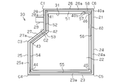
シール材40は、6つの屈曲部41~46を有している。第1の屈曲部41は、上壁部26と第3の側壁部28とが交わる角C1で曲げられている。第2の屈曲部42は、第3の側壁部28と傾斜壁部27とが交わる角C2で曲げられている。第3の屈曲部43は、傾斜壁部27と第2の側壁部25とが交わる角C3で曲げられている。第4の屈曲部44は、第2の側壁部25と下壁部23とが交わる角C4で曲げられている。第5の屈曲部45は、下壁部23と第1の側壁部24とが交わる角C5で曲げられている。第6の屈曲部46は、第1の側壁部24と上壁部26とが交わる角C6で曲げられている。
シール材40は、長手方向の一方の端部に第1端部40aを有し、他方の端部に第2端部40bを有している。シール材40は、第1端部40aと第1の屈曲部41との間に、上部51を有している。上部51は、上壁部26の端面26aに沿って配置されている。シール材40は、第1の屈曲部41と第2の屈曲部42との間に、側部52を有している。側部52は、第3の側壁部28の端面28aに沿って配置されている。シール材40は、第2の屈曲部42と第3の屈曲部43との間に、傾斜部53を有している。傾斜部53は、傾斜壁部27の端面27aに沿って配置されている。シール材40は、第3の屈曲部43と第4の屈曲部44との間に、側部54を有している。側部54は、第2の側壁部25の端面25aに沿って配置されている。シール材40は、第4の屈曲部44と第5の屈曲部45との間に、下部55を有している。下部55は、下壁部23の端面23aに沿って配置されている。シール材40は、第5の屈曲部45と第6の屈曲部46との間に、側部56を有している。側部56は、第1の側壁部24の端面24aに沿って配置されている。
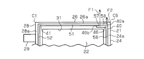
図3に示すように、シール材40は、第6の屈曲部46と第2端部40bとの間に、内側重なり部57を有している。内側重なり部57は、上壁部26の端面26aに沿って配置されている。内側重なり部57は、上部51よりも内側に配置されている。内側重なり部57の長さは、上部51よりも小さい。内側重なり部57は、上部51の一部と密着している。上部51は、内側重なり部57と重なり合う部分に、外側重なり部58を有している。外側重なり部58は、上壁部26の端面26aに沿って配置されている。外側重なり部58は、内側重なり部57よりも外側に配置されている。外側重なり部58は、第6の屈曲部46を上方から覆っている。内側重なり部57及び外側重なり部58は、壁部23~28の端面23a~28aのうち最も上方に位置する端面26aに配置されている。
シール材40は、弾性力を有している。このため、シール材40を屈曲させると、シール材40には、元の形状に復元するための復元力が作用する。内側重なり部57に作用する復元力F1は、内側重なり部57に最も近い第6の屈曲部46に依存している。第6の屈曲部46は、第1の側壁部24の端面24aから上壁部26の端面26aに向けて屈曲されている。内側重なり部57には、内側重なり部57を側部56と一直線状にさせるべく、復元力F1が外側に作用する。このため、内側重なり部57の復元力F1は、外側重なり部58に作用する。したがって、第6の屈曲部46は、内側重なり部57が外側重なり部58に押しつけられるよう内側重なり部57に復元力F1を作用させる内側屈曲部である。
また、外側重なり部58には、復元力F2も作用する。復元力F2は、外側重なり部58を含む上部51に最も近い屈曲部である第1の屈曲部41に依存している。外側重なり部58には、外側重なり部58を側部52と一直線状にさせるべく、復元力F2が外側に作用する。すなわち、内側重なり部57と外側重なり部58とには、復元力が同一方向にそれぞれ作用する。また、外側重なり部58には、復元力F2が、内側重なり部57から離れる方向に作用する。
シール材40に作用する復元力は、各屈曲部41~46からの距離に依存している。つまり、各屈曲部41~46からの距離が近い部分ほど、シール材40に作用する復元力は大きくなる。内側重なり部57に作用する復元力F1の大きさは、第6の屈曲部46からの距離に依存している。外側重なり部58に作用する復元力F2の大きさは、第1の屈曲部41からの距離に依存している。第1の屈曲部41から外側重なり部58までの距離は、第6の屈曲部46から内側重なり部57までの距離に比べて大きい。このため、外側重なり部58に作用する復元力F2は、内側重なり部57に作用する復元力F1に比べて小さい。したがって、内側重なり部57と外側重なり部58とに作用する復元力の方向が同じであっても、内側重なり部57は、外側重なり部58に押しつけられる。
次に、上記の電池パック10の作用について説明する。
ケース本体21と蓋体13とをシールする場合、長尺状のシール材40が屈曲した状態でケース本体21と蓋体13との間に配置される。この場合、シール材40は、ケース本体21と蓋体13との間に隙間なくかつ開口部31を囲むように配置される。また、シール材40は、互いに重なり合う内側重なり部57と外側重なり部58とを有するように配置される。このとき、内側重なり部57と外側重なり部58との間に隙間が生じると、シール性を確保できないおそれがある。
ケース本体21と蓋体13とをシールする場合、長尺状のシール材40が屈曲した状態でケース本体21と蓋体13との間に配置される。この場合、シール材40は、ケース本体21と蓋体13との間に隙間なくかつ開口部31を囲むように配置される。また、シール材40は、互いに重なり合う内側重なり部57と外側重なり部58とを有するように配置される。このとき、内側重なり部57と外側重なり部58との間に隙間が生じると、シール性を確保できないおそれがある。
本実施形態では、内側重なり部57には、外側重なり部58に向けて復元力F1が作用している。これにより、内側重なり部57が外側重なり部58に押しつけられるため、内側重なり部57と外側重なり部58との密着性が向上する。このため、内側重なり部57と外側重なり部58との間には、隙間が生じにくくなる。よって、ケース本体21と蓋体13との間のシール性が向上する。
したがって、上記実施形態によれば、以下のような効果を得ることができる。
(1)内側重なり部57には、外側重なり部58に向けて復元力F1が作用している。このため、内側重なり部57と外側重なり部58との密着性が向上し、ケース11のシール性が向上する。このため、ケース11内には、外部から液体やほこりなどが侵入しにくくなる。よって、電池セル12の短絡が抑止される。
(1)内側重なり部57には、外側重なり部58に向けて復元力F1が作用している。このため、内側重なり部57と外側重なり部58との密着性が向上し、ケース11のシール性が向上する。このため、ケース11内には、外部から液体やほこりなどが侵入しにくくなる。よって、電池セル12の短絡が抑止される。
(2)内側重なり部57及び外側重なり部58は、ケース11の最上部で互いに重なり合っている。電池パック10は、車両などの収容部に収容されることがある。この場合、内側重なり部57と外側重なり部58とがケース11の下部に設けられていると、収容部に滞留した液体がケース11内に侵入しやすくなる。この点、内側重なり部57及び外側重なり部58をケース11の最上部に設けることで、収容部に滞留した液体がケース11に侵入しにくくなる。
(3)外側重なり部58は、第6の屈曲部46を上方から覆っている。外側重なり部58が第6の屈曲部46を覆っていない場合、第6の屈曲部46と内側重なり部57との間に液体が滞留したり、内側重なり部57と外側重なり部58との継ぎ目から液体が侵入したりするおそれがある。この点、第6の屈曲部46を覆う位置まで外側重なり部58を延ばすことで、内側重なり部57と外側重なり部58との継ぎ目付近に液体が滞留することを防止できる。よって、ケース11内への液体の侵入を防止することができる。
上記の実施形態は、以下のように変更してもよい。
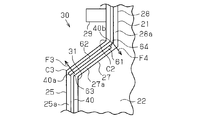
図4に示すように、傾斜壁部27の端面27aに、内側重なり部61と外側重なり部62とを配置してもよい。内側重なり部61には、角C3で曲げられた内側屈曲部63により、復元力F3が外側に作用している。外側重なり部62には、角C2で曲げられた外側屈曲部64により、復元力F4が内側に作用している。すなわち、内側重なり部61と外側重なり部62とには、復元力が、互いに近づく方向にそれぞれ作用している。このため、内側重なり部61と外側重なり部62との密着性が向上し、ケース11のシール性が更に向上する。
図4に示すように、傾斜壁部27の端面27aに、内側重なり部61と外側重なり部62とを配置してもよい。内側重なり部61には、角C3で曲げられた内側屈曲部63により、復元力F3が外側に作用している。外側重なり部62には、角C2で曲げられた外側屈曲部64により、復元力F4が内側に作用している。すなわち、内側重なり部61と外側重なり部62とには、復元力が、互いに近づく方向にそれぞれ作用している。このため、内側重なり部61と外側重なり部62との密着性が向上し、ケース11のシール性が更に向上する。
また、傾斜壁部27は、凹部30を区画する壁部の一つである。また、傾斜部27には、コネクタ29が設けられていない。内側重なり部61と外側重なり部62とを配置する部分には、シール材40が二重で設けられる。このため、内側重なり部61と外側重なり部62とが配置されるケース11の壁部の端面は、面積を広くする必要がある。この場合、壁部を厚くして端面の面積を広くすることが考えられる。しかしながら、この方法は、電池パック10以外の他の部材の配置を阻害するおそれがあり、好ましくない。この点、コネクタ29が配置される凹部30を区画する壁部は、以下の利点を有している。即ち、コネクタ29との接触を抑止するためコネクタ29との間に空隙を有しており、また、この空隙に他の部材が設けられることもない。よって、凹部30を区画する壁部は、他の壁部よりも厚くしやすい。このため、内側重なり部61と外側重なり部62とが配置される傾斜壁部27を厚くしても、他の部材の配置は阻害されにくい。
図5に示すように、内側重なり部71と外側重なり部72とを、第1の側壁部24に配置してもよい。内側重なり部71には、角C5で曲げられた内側屈曲部73によって、復元力F5が外側に作用している。このため、内側重なり部71と外側重なり部72との密着性が向上し、ケース11のシール性が更に向上する。この場合、内側重なり部71が上方に延び、外側重なり部72が下方に延びていることが好ましい。内側重なり部71が下方に延び、外側重なり部72が上方に延びている場合、内側重なり部71と外側重なり部72との継ぎ目が上方を向いて露出される。液体は上から下に移動するため、上方を向いて露出された継ぎ目から、液体が侵入しやすい。この点、内側重なり部71が上方に延び、外側重なり部72が下方に延びていることで、継ぎ目が上方を向いて露出されなくなり、ケース11内への液体の侵入を防止できる。
図6に示すように、第3の側壁部28に、内側重なり部81と外側重なり部82とを配置してもよい。この場合も、内側重なり部81と外側重なり部82とには、復元力F6,F7が、互いに近付く方向にそれぞれ作用する。このため、内側重なり部81と外側重なり部82との密着性が向上する。
第2の側壁部25や下壁部23に、内側重なり部57と外側重なり部58とを配置してもよい。すなわち、内側重なり部57と外側重なり部58とを、開口部31を囲む端面23a~28aの任意の位置に配置してもよい。
開口部31の形状は、四角形や五角形など、任意の形状であってもよい。
複数のシール材40を用いてもよい。この場合、シール材40同士が重なり合う部分が、内側重なり部57及び外側重なり部58となる。また、シール材40の数が増すにつれ、内側重なり部57と外側重なり部58との数も増える。
複数のシール材40を用いてもよい。この場合、シール材40同士が重なり合う部分が、内側重なり部57及び外側重なり部58となる。また、シール材40の数が増すにつれ、内側重なり部57と外側重なり部58との数も増える。
Claims (6)
- 電池セルと、前記電池セルを収容するケースとを備えた電池パックであって、前記ケースは、
開口部を有するケース本体と、
前記ケース本体に固定されて、前記開口部を閉塞する蓋体と、
前記ケース本体の開口部を囲む端面と前記蓋体との間に挟持され、前記開口部の形状に沿って屈曲された長尺状の弾性力を有するシール材とを備え、前記シール材は、
内側重なり部と、
前記内側重なり部と重なり合うとともに前記内側重なり部よりも外側に配置される外側重なり部と、
前記内側重なり部が前記外側重なり部に押しつけられるよう前記内側重なり部に復元力を作用させる内側屈曲部と
を有することを特徴とする電池パック。 - 請求項1記載の電池パックにおいて、
前記シール材は、前記外側重なり部が前記内側重なり部に押しつけられるよう前記外側重なり部に復元力を作用させる外側屈曲部を有することを特徴とする電池パック。 - 請求項1又は2に記載の電池パックにおいて、
前記内側重なり部と前記外側重なり部とは、前記ケースの最上部に設けられていることを特徴とする電池パック。 - 請求項3に記載の電池パックにおいて、
前記外側重なり部は、前記内側屈曲部を覆うことを特徴とする電池パック。 - 請求項1又は2に記載の電池パックにおいて、
前記ケースは、前記ケースの内側に凹む凹部を有し、
前記凹部により、前記電池セルに電気的に接続されるコネクタが配置される領域が、前記ケースの外部に区画され、
前記凹部を区画する前記ケースの壁部のうち、前記コネクタが設けられる壁部と異なる壁部の端面に、前記内側重なり部と前記外側重なり部とが設けられていることを特徴とする電池パック。 - 請求項1又は2に記載の電池パックにおいて、
前記内側重なり部は、鉛直方向の上方に延び、
前記外側重なり部は、鉛直方向の下方に延びていることを特徴とする電池パック。
Priority Applications (3)
| Application Number | Priority Date | Filing Date | Title |
|---|---|---|---|
| US15/302,249 US10714718B2 (en) | 2014-04-18 | 2015-02-27 | Battery pack |
| CN201580019448.0A CN106233496B (zh) | 2014-04-18 | 2015-02-27 | 电池组 |
| DE112015001875.1T DE112015001875T5 (de) | 2014-04-18 | 2015-02-27 | Batteriepackung |
Applications Claiming Priority (2)
| Application Number | Priority Date | Filing Date | Title |
|---|---|---|---|
| JP2014086854A JP6233168B2 (ja) | 2014-04-18 | 2014-04-18 | 電池パック |
| JP2014-086854 | 2014-04-18 |
Publications (1)
| Publication Number | Publication Date |
|---|---|
| WO2015159595A1 true WO2015159595A1 (ja) | 2015-10-22 |
Family
ID=54323812
Family Applications (1)
| Application Number | Title | Priority Date | Filing Date |
|---|---|---|---|
| PCT/JP2015/055753 WO2015159595A1 (ja) | 2014-04-18 | 2015-02-27 | 電池パック |
Country Status (5)
| Country | Link |
|---|---|
| US (1) | US10714718B2 (ja) |
| JP (1) | JP6233168B2 (ja) |
| CN (1) | CN106233496B (ja) |
| DE (1) | DE112015001875T5 (ja) |
| WO (1) | WO2015159595A1 (ja) |
Families Citing this family (5)
| Publication number | Priority date | Publication date | Assignee | Title |
|---|---|---|---|---|
| JP6657919B2 (ja) * | 2015-12-18 | 2020-03-04 | 株式会社豊田自動織機 | 電池パック |
| JP2018037185A (ja) * | 2016-08-30 | 2018-03-08 | 株式会社豊田自動織機 | 電池パック |
| JP6794767B2 (ja) * | 2016-10-19 | 2020-12-02 | 株式会社豊田自動織機 | 電池パック |
| JP6787148B2 (ja) * | 2017-01-23 | 2020-11-18 | 株式会社豊田自動織機 | 電池パック |
| KR102270269B1 (ko) * | 2018-01-17 | 2021-06-28 | 주식회사 엘지에너지솔루션 | 리유즈, 리사이클 내지 리웍이 용이한 접착 구조를 갖는 배터리 모듈 하우징 및 이를 포함하는 배터리 모듈 |
Citations (4)
| Publication number | Priority date | Publication date | Assignee | Title |
|---|---|---|---|---|
| JPH07317907A (ja) * | 1994-05-30 | 1995-12-08 | Mitsubishi Heavy Ind Ltd | 軟質パッキン材 |
| US6352267B1 (en) * | 1999-03-12 | 2002-03-05 | John E. Rode | Adjustaby sizeable ring seal |
| JP2003120815A (ja) * | 2001-10-18 | 2003-04-23 | Japan Gore Tex Inc | 矩形シール材 |
| JP2013207114A (ja) * | 2012-03-28 | 2013-10-07 | Fujitsu Ltd | 筐体 |
Family Cites Families (15)
| Publication number | Priority date | Publication date | Assignee | Title |
|---|---|---|---|---|
| JPS6482457A (en) * | 1987-09-25 | 1989-03-28 | Fuji Electrochemical Co Ltd | Button type alkaline-manganese cell |
| JPH0648266Y2 (ja) * | 1987-11-20 | 1994-12-12 | 三洋電機株式会社 | 温風コタツ |
| JP2005339995A (ja) * | 2004-05-27 | 2005-12-08 | Matsushita Electric Ind Co Ltd | 扁平形有機電解液電池 |
| EP1878085B1 (en) * | 2005-03-14 | 2016-04-20 | Johnson Controls Technology Company | Lithium battery system |
| KR100644776B1 (ko) * | 2005-05-27 | 2006-11-14 | 유병훈 | 공기 아연 전지 및 그 제조 방법 |
| EP1886364B1 (en) * | 2005-05-27 | 2011-08-17 | E.M.W. Energy Co., Ltd. | Battery and method for producing the same |
| US7816026B2 (en) * | 2006-09-22 | 2010-10-19 | Eveready Battery Company, Inc. | Battery having air electrode and biased lever gasket |
| JP5180505B2 (ja) | 2007-03-30 | 2013-04-10 | 三菱重工業株式会社 | 電池モジュール |
| JP4739264B2 (ja) * | 2007-03-30 | 2011-08-03 | Nok株式会社 | 密封構造及びガスケット |
| EP2525426B1 (en) * | 2010-01-15 | 2017-10-18 | Mitsubishi Jidosha Kogyo Kabushiki Kaisha | Battery case for vehicle |
| US9331321B2 (en) * | 2011-03-31 | 2016-05-03 | GM Global Technology Operations LLC | Fabric composite support or enclosure for an automotive battery pack |
| KR101590688B1 (ko) * | 2011-06-10 | 2016-02-01 | 후지쯔 가부시끼가이샤 | 휴대형 전자 기기 및 방수 커버 |
| US8574021B2 (en) * | 2011-09-23 | 2013-11-05 | Mattel, Inc. | Foldable toy vehicles |
| CN203423217U (zh) * | 2013-06-25 | 2014-02-05 | 常州市宇峰电源有限公司 | 防泄漏纽扣电池 |
| DE102015217076A1 (de) * | 2015-09-07 | 2017-03-09 | Robert Bosch Gmbh | Gehäuse für eine Mehrzahl von elektrischen Energiespeichereinheiten |
-
2014
- 2014-04-18 JP JP2014086854A patent/JP6233168B2/ja active Active
-
2015
- 2015-02-27 DE DE112015001875.1T patent/DE112015001875T5/de active Pending
- 2015-02-27 US US15/302,249 patent/US10714718B2/en active Active
- 2015-02-27 WO PCT/JP2015/055753 patent/WO2015159595A1/ja active Application Filing
- 2015-02-27 CN CN201580019448.0A patent/CN106233496B/zh active Active
Patent Citations (4)
| Publication number | Priority date | Publication date | Assignee | Title |
|---|---|---|---|---|
| JPH07317907A (ja) * | 1994-05-30 | 1995-12-08 | Mitsubishi Heavy Ind Ltd | 軟質パッキン材 |
| US6352267B1 (en) * | 1999-03-12 | 2002-03-05 | John E. Rode | Adjustaby sizeable ring seal |
| JP2003120815A (ja) * | 2001-10-18 | 2003-04-23 | Japan Gore Tex Inc | 矩形シール材 |
| JP2013207114A (ja) * | 2012-03-28 | 2013-10-07 | Fujitsu Ltd | 筐体 |
Also Published As
| Publication number | Publication date |
|---|---|
| US10714718B2 (en) | 2020-07-14 |
| CN106233496B (zh) | 2019-01-15 |
| CN106233496A (zh) | 2016-12-14 |
| JP6233168B2 (ja) | 2017-11-22 |
| DE112015001875T5 (de) | 2016-12-29 |
| US20170033340A1 (en) | 2017-02-02 |
| JP2015207427A (ja) | 2015-11-19 |
Similar Documents
| Publication | Publication Date | Title |
|---|---|---|
| WO2015159595A1 (ja) | 電池パック | |
| JP6094740B2 (ja) | 電装ケース | |
| JP6860823B2 (ja) | 防水コネクタ | |
| JP2011194982A (ja) | 車両用バッテリーケース | |
| KR101592663B1 (ko) | 연료전지용 스택 | |
| EP3578421A1 (en) | Liquid-proof structure of fitting body, electrical connection box, and wire harness | |
| US10340482B2 (en) | Energy storage apparatus | |
| KR20140047899A (ko) | 밀폐케이스 | |
| US20160036103A1 (en) | Energy storage apparatus | |
| JP2015118804A5 (ja) | ||
| JP2020072056A (ja) | コネクタ | |
| JP2012178370A (ja) | 電池モジュール | |
| JP6024611B2 (ja) | コネクタ | |
| JP2016127640A (ja) | 密封箱および密封構造 | |
| JP6071649B2 (ja) | 電気的素子のシール構造 | |
| JP6724497B2 (ja) | 電池パック | |
| JP6896924B2 (ja) | アキュムレータ | |
| JP6343169B2 (ja) | グロメット、及び、ワイヤーハーネス | |
| JP5145010B2 (ja) | シール体、及びそのシール体を有するコネクタ | |
| JP2013101218A (ja) | 表示装置のフロントユニット | |
| WO2016039066A1 (ja) | 防水カバーを備えた電気装置及び防水カバー | |
| JP2016092055A (ja) | ケース | |
| JP2010272561A (ja) | 防水構造 | |
| JP2014184897A (ja) | グロメット | |
| JP3192780U (ja) | グロメット |
Legal Events
| Date | Code | Title | Description |
|---|---|---|---|
| 121 | Ep: the epo has been informed by wipo that ep was designated in this application |
Ref document number: 15780172 Country of ref document: EP Kind code of ref document: A1 |
|
| WWE | Wipo information: entry into national phase |
Ref document number: 15302249 Country of ref document: US |
|
| WWE | Wipo information: entry into national phase |
Ref document number: 112015001875 Country of ref document: DE |
|
| 122 | Ep: pct application non-entry in european phase |
Ref document number: 15780172 Country of ref document: EP Kind code of ref document: A1 |